epson eb-1460ui/eb-1450ui/eb-1440ui installation … · inspect the setting plate on a regular...
TRANSCRIPT

Installation Guide

Using the Product Safely
1
Safety Instructions
For your safety, read all the instructions in this guide before using this product. Incorrect handling that ignoresinstructions in this guide could damage this product or could result in personal injury or property damage.Keep this installation guide at hand for future reference.
Read the User's Guide and Safety Instructions for your projector and follow the instructions in these documents.
Safety indications
The documentation and this product use graphical symbols to show how to use this product safely.
The indications and their meaning are as follows. Make sure you understand them properly before readingthe guide.
Symbol Explanation
Warning This symbol indicates information that, if ignored, could possibly result in personal injury oreven death due to incorrect handling.
Caution This symbol indicates information that, if ignored, could possibly result in personal injury orphysical damage due to incorrect handling.
Explanation of Symbols
Symbols Explanation
Symbol indicating an action that must not be done
Symbol indicating an action that should be done
cSymbol indicating related or useful information
Safety Precautions for Installation
Warning
The setting plate is exclusively for mounting the projector on a wall. If anything other thana projector is mounted, the weight may result in damage.
If this product falls, it could cause death or personal injury.
The installation work (wall mounting) should be performed by specialists who have tech-nical knowledge and ability. Incomplete or incorrect installation could cause the productto fall and cause personal injury or property damage.
Follow the instructions in this guide when installing this product.
If the instructions are not followed, this product may fall, resulting in personal injury or an accident.

Using the Product Safely
2
Warning
Handle the power cord carefully.
Incorrect handling may cause fire or electric shock. Observe the following precautions when han-dling:
• Do not handle the power plug with wet hands.• Do not use a power cord that is damaged or modified.• Do not pull the power cord with too much force when routing the cable through the setting plate.
Do not install the setting plate in a place where it might be subjected to vibration or shock.
This could cause damage to the projector or mounting surface. If this product falls, it could causedeath or personal injury.
Install the setting plate so that it can sufficiently support the mass of the projector andsetting plate, and resist any horizontal vibration. Use M10 nuts and bolts.
Nuts and bolts smaller than M10 could cause the setting plate to fall. Epson accepts no responsibilityfor any damage or injury caused by lack of wall strength or inadequate installation.
The installation work should be performed by at least two qualified service personnel. Ifyou need to loosen any screws during installation, be careful not to drop this product.
If this product falls, it could cause death or personal injury.
When mounting this product on a wall, the wall requires enough strength to hold theprojector and the setting plate.
This product should be installed on a concrete wall. The maximum combined weight of the pro-jector and the setting plate is approximately 16 kg (not including cables). Ensure the strength ofthe wall before mounting this product on the wall. If the wall is not strong enough, reinforce thewall before installation.
Inspect the setting plate on a regular basis to ensure there are no broken parts or loosescrews.
If any parts are damaged, stop using the setting plate immediately. If this product falls, it couldcause death or personal injury.
Do not disassemble or remodel this product.
There are numerous high-voltage sections inside the product that could cause a fire, electric shock,or an accident.
Do not hang on this product or hang a heavy object on this product.
If this product falls, it could cause death or personal injury.
Do not use adhesives, lubricants, or oils to install or adjust the setting plate.
If you use adhesives to prevent the screws from loosening or things such as lubricants or oils onthe slide plate fixing part of the projector, the case may crack and cause the projector to fall,resulting in personal injury or property damage.
Tighten all screws firmly after adjustment.
Otherwise, the product may fall and cause personal injury or property damage.
Never loosen the bolts and nuts after installation.
Confirm that the screws have not become loose on a regular basis. If you find any loose screws,tighten them firmly. Otherwise, the product may fall and cause personal injury or property damage.
Route the cables so that they are not interfered with the nuts and bolts.
Incorrect handling of the cables may cause fire or electric shock.

Using the Product Safely
3
Warning
When turning on the projector, do not look into the projection window.
This could cause damage to eyesight due to the powerful light emitted. Take particular care whenthere are children present. When turning on the projector at a distance using the remote control,make sure there is no one looking into the projection window.
When using the projector, do not place any objects or put your hand near the projectionwindow.
This area is dangerous as it reaches a high temperature due to the concentrated projection light.
Do not cover the projector's air intake vent or air exhaust vent. If either of the vents arecovered, the internal temperature could rise and cause a fire.
Avoid locations subject to high temperatures, such as close to heaters, and leave a gap of at least50 cm between the wall and the air exhaust vent.
Do not use the projector in a location subject to combustible or explosive gas.
The projector may catch fire because of the high temperature of the lamp inside the projector.
If any abnormalities occur with this product, immediately disconnect the cables from theproduct, and then contact your local dealer or the nearest Epson service call center.
Continuing to use the product in an abnormal condition could cause a fire, electric shock, or visualimpairment.
Caution
Do not install this product in a location where the operating temperature for your projectormodel may be exceeded.
Such an environment may damage the projector.
Install this product in a place free from excessive dust and humidity to prevent the lens oroptical components from becoming dirty.
Do not use excessive force when adjusting this product.
This product may break, resulting in personal injury.
Notes on handling the Touch Unit (EB-1460Ui/EB-1450Ui only)
Warning
Do not disassemble or remodel the Touch Unit.
The Touch Unit contains a high power laser product that could cause a fire, electric shock, or anaccident.
Only connect the Touch Unit to the EB-1460Ui/EB-1450Ui. Do not connect it to any otherprojectors or devices.
The device could malfunction, or laser light that is higher than normal intensity could be emitted.
Do not go near the Touch Unit if you are using medical equipment such as a pace maker.Furthermore, when using the Touch Unit, make sure there is no one using medical equip-ment such as a pace maker, in the surrounding area.
A powerful magnet within the unit generates electromagnetic interference which may cause med-ical equipment to malfunction.

Using the Product Safely
4
Caution
Do not go near the Touch Unit with magnetic storage media such as magnetic cards, orprecision electronic devices such as computers, digital watches, or mobile phones.
A powerful magnet within the unit could corrupt data or cause a malfunction.
About This Installation Guide
This guide describes how to mount the ultra short-throw projector EB-1460Ui/EB-1450Ui/EB-1440Ui on a wall.
It also describes how to install the Touch Unit (EB-1460Ui/EB-1450Ui only), Control Pad, and Pen Stand aftermounting on a wall.

Using the Product Safely
5
Choosing an Installation Location
Projector installation location
• Carry out power supply wiring work for the installation location of the setting plate in advance.• Install the projector away from other electric devices such as fluorescent lights or air conditioners. Some kinds of
fluorescent lights could interfere with the remote control of the projector.• When installing the projector, make sure there is a gap of at least 50 cm from the wall to the projector's air exhaust
and intake vents on the left and right.
• When installing two or more projectors in parallel, make sure the temperature of the surrounding environment isless than 35°C.
If the environment is too hot, the projector may overheat and the power may turn off without warning. When usingthe projector in an environment of 35°C or more, install a partition to block the heat vented from the projector's airexhaust vent. Make sure the partition is slightly larger than the exhaust vent (approx. 2 cm wider and taller), and theninstall the partition 10 to 30 cm from the exhaust vent.
• It is recommended to keep connection cable length less than 20 meters to reduce external noise.• We recommend using stick-on screens or board screens.• Install the projector so that it is tilted at an angle of no more than ±3° vertically and horizontally in relation to the screen.• When using the interactive function (Easy Interactive Function), install so that the projected image is within reach.• Do not install the projector or the screen in a location subject to direct sunlight. If the projector or the screen are
subject to direct sunlight, the interactive function may not operate correctly.

Using the Product Safely
6
Touch Unit installation location (EB-1460Ui/EB-1450Ui only)
• When using the Touch Unit, install the projector using one of the following methods. The Touch Unit cannot be usedif another installation method is used.
• Mount the projector on a wall or suspend it from a ceiling and project images from in front of the screen.• Install vertically on a table and project from the front of the desk. (When installing vertically on a table, you need
the optional Interactive Table Mount (ELPMB29).)• Before installing the Touch Unit, make sure that the installation surface is not warped or distorted, and that any
unevenness on the screen surface is less than 5 mm.
• When installing the Touch Unit on a whiteboard, secure the Touch Unit with magnets or screws.
• When installing the Touch Unit outside the whiteboard, you need the supplied Touch Unit Bracket.
Using the Product Safely
7
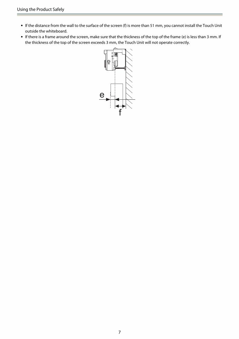
• If the distance from the wall to the surface of the screen (f) is more than 51 mm, you cannot install the Touch Unitoutside the whiteboard.
• If there is a frame around the screen, make sure that the thickness of the top of the frame (e) is less than 3 mm. Ifthe thickness of the top of the screen exceeds 3 mm, the Touch Unit will not operate correctly.

Contents
8
Using the Product SafelySafety Instructions . . . . . . . . . . . . . . . . . . . . 1
Safety indications . . . . . . . . . . . . . . . . . . . . . . . 1
Explanation of Symbols . . . . . . . . . . . . . . . . . . . 1
Safety Precautions for Installation . . . . . . . . . . . . 1
Notes on handling the Touch Unit (EB-1460Ui/EB-1450Ui only) . . . . . . . . . . . . . . . . . . . . . . . . . 3
About This Installation Guide . . . . . . . . . . . . . . . 4
Choosing an Installation Location . . . . . . 5
Projector installation location . . . . . . . . . . . . . . . 5
Touch Unit installation location (EB-1460Ui/EB-1450Ui only) . . . . . . . . . . . . . . . . . . . . . . . . . 6
Installation GuideInstallation Work Flow . . . . . . . . . . . . . . . 10
Installing one projector . . . . . . . . . . . . . . . . . . 10
When two or more projectors are installed inparallel . . . . . . . . . . . . . . . . . . . . . . . . . . . . . . 11
Package Contents . . . . . . . . . . . . . . . . . . . . 12
Setting plate . . . . . . . . . . . . . . . . . . . . . . . . . . 12
Control Pad . . . . . . . . . . . . . . . . . . . . . . . . . . . 13
Touch Unit (EB-1460Ui/EB-1450Ui only) . . . . . . . 13
Touch Unit Bracket . . . . . . . . . . . . . . . . . . . . 14
Specifications . . . . . . . . . . . . . . . . . . . . . . . 15
Setting plate . . . . . . . . . . . . . . . . . . . . . . . . . . 15
Wall plate cover . . . . . . . . . . . . . . . . . . . . . . 15
Wall plate . . . . . . . . . . . . . . . . . . . . . . . . . . 16
Vertical slide adjustment range . . . . . . . . . . . 16
Horizontal slide adjustment range . . . . . . . . . 17
Forward/backward slide adjustment range . . 17
Position for installing accessories . . . . . . . . . 18
Control Pad/Pen Stand . . . . . . . . . . . . . . . . . . . 18
Control Pad (external dimensions/weight) . . . 18
Cable routing holes . . . . . . . . . . . . . . . . . . . 19
Pen Stand (external dimensions/weight) . . . . 19
Touch Unit (EB-1460Ui/EB-1450Ui only) . . . . . . . 19
Touch Unit (external dimensions/weight) . . . 19
Touch Unit Bracket (external dimensions/adjustment range/weight) . . . . . . . . . . . . . . 20
Attached labels . . . . . . . . . . . . . . . . . . . . . . 21
Laser diffusion port . . . . . . . . . . . . . . . . . . . 21
Projection Distance Table . . . . . . . . . . . . 23
Figures of Installation Dimensions . . . . . . . . . . . 23
When installing the Touch Unit (EB-1460Ui/EB-1450Ui only) . . . . . . . . . . . . . . . . . . . . . . 24
When installing the Control Pad and the PenStand . . . . . . . . . . . . . . . . . . . . . . . . . . . . . 27
When Projected Image is Smaller than 85 Inches 28
16:10 projected image . . . . . . . . . . . . . . . . . 29
When Projected Image is 85 inches or more . . . . 30
16:10 projected image . . . . . . . . . . . . . . . . . 31
Installing the Setting Plate . . . . . . . . . . . 32
Connecting Devices . . . . . . . . . . . . . . . . . . . . . 32
Necessary cables . . . . . . . . . . . . . . . . . . . . . 32
Installation Procedure . . . . . . . . . . . . . . . . . . . 36
Assemble the parts . . . . . . . . . . . . . . . . . . . 36
Install the wall plate on the wall . . . . . . . . . . 38
Determine the projection distance, and thenpass the cables through the setting plate . . . . 40
Attaching the setting plate to the wall plate . . 42
Securing the projector to the setting plate . . . 44
Adjusting the Position of the Projector . . . . . . . 46
Sticking the infrared deflectors (EB-1460Ui/EB-1450Ui only) . . . . . . . . . . . . . . . . . . . . . . 52
Arc Correction . . . . . . . . . . . . . . . . . . . . . . . 53
Calibrating the pen . . . . . . . . . . . . . . . . . . . . . 54
Attaching the Covers . . . . . . . . . . . . . . . . . . . . 58
Installing the Control Pad and the PenStand . . . . . . . . . . . . . . . . . . . . . . . . . . . . . . . 61
Installing the Control Pad . . . . . . . . . . . . . . . . . 61
Installing the Pen Stand . . . . . . . . . . . . . . . . . . 62
Installing the Touch Unit (EB-1460Ui/EB-1450Ui only) . . . . . . . . . . . . . . . . . . . . . 64
When installing the Touch Unit outside thewhiteboard (using the Touch Unit Bracket) . . . . 64
Installation Procedure . . . . . . . . . . . . . . . . . 64
Angle Adjustment . . . . . . . . . . . . . . . . . . . . 69
Touch Calibration . . . . . . . . . . . . . . . . . . . . 84
When installing the Touch Unit on thewhiteboard (without using the Touch UnitBracket) . . . . . . . . . . . . . . . . . . . . . . . . . . . . . . 87
Installation Procedure . . . . . . . . . . . . . . . . . 87

Contents
9
Angle Adjustment . . . . . . . . . . . . . . . . . . . . 91
AppendixInstalling Multiple Projectors inParallel (Multi-Projection) . . . . . . . . . . . . 95
Multi-Projection settings . . . . . . . . . . . . . . . . . 95
Setting the Projector ID . . . . . . . . . . . . . . . . 95
Adjusting the Image in Multi-Projection . . . . . 98
When two projectors are installed in paralleland you are using the interactive function . . . . . 99
Setting the projectors in sync . . . . . . . . . . . 100
Setting Multi-Projection Interactive . . . . . . . 101
Batch Setup Function . . . . . . . . . . . . . . . 108
Setup Using a USB flash drive . . . . . . . . . . . . . 109
Saving settings to the USB flash drive . . . . . 109
Copying saved settings to other projectors . 111
When Setup Fails . . . . . . . . . . . . . . . . . . . . . . 112
Attaching a Security Cable . . . . . . . . . . . 113
General Notice . . . . . . . . . . . . . . . . . . . . . 114

Installation Guide
10
Installation Work Flow
Installing one projector
Follow the procedures below to mount the projector on a wall.
a Installing the Setting Plate and the Projector (s p.32)
b Adjusting the Position of the Projector (s p.46)
c Calibrating the Interactive Pen (s p.54)
d Installing the Control Pad and the Pen Stand (s p.61)
When installing the Touch Unit, finish installing the projector first, and then follow the procedures below.(EB-1460Ui/EB-1450Ui only)
The procedure differs depending on where the Touch Unit is to be installed.
When installing the Touch Unit outside the whiteboard (using the Touch Unit Bracket)
a Installing the Touch Unit (s p.64)
b Adjusting the Angle of Laser Diffusion (s p.69)
c Performing Touch Calibration (s p.84)
When installing the Touch Unit on the whiteboard (without using the Touch Unit Bracket)

Installation Guide
11
a Installing the Touch Unit (s p.87)
b Adjusting the Angle of Laser Diffusion (s p.91)
c Performing Touch Calibration (s p.84)
When two or more projectors are installed in parallel
When using the multi-projection function (when multiple projectors are installed in parallel to project one,large screen), follow the steps below.
a Installing the Setting Plate and the Projector (s p.32)
b Adjusting the Position of the Projector (s p.46)
c Setting the Projector ID (s p.95)
d Adjusting the Image in Multi-Projection (s p.98)
When two projectors are installed in parallel and you want to use the interactive function, make the followingsettings. Make the settings for each projector.
a Setting Projector Synchronization (s p.100)
b Setting Multi-Projection Interactive (s p.101)
Installation Guide
12
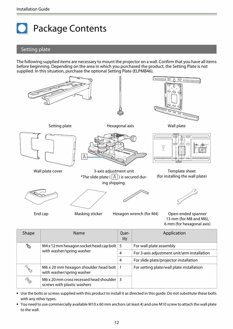
Package Contents
Setting plate
The following supplied items are necessary to mount the projector on a wall. Confirm that you have all itemsbefore beginning. Depending on the area in which you purchased the product, the Setting Plate is notsupplied. In this situation, purchase the optional Setting Plate (ELPMB46).
Setting plate Hexagonal axis Wall plate
Wall plate cover 3-axis adjustment unit*The slide plate ( ) is secured dur-
ing shipping.
Template sheet(for installing the wall plate)
End cap Masking sticker Hexagon wrench (for M4) Open-ended spanner13 mm (for M8 and M6),
6 mm (for hexagonal axis)
Shape Name Quan-tity
Application
M4 x 12 mm hexagon socket head cap boltwith washer/spring washer
5 For wall plate assembly
4 For 3-axis adjustment unit/arm installation
4 For slide plate/projector installation
M6 x 20 mm hexagon shoulder head boltwith washer/spring washer
1 For setting plate/wall plate installation
M6 x 20 mm cross recessed head shoulderscrews with plastic washers
3
• Use the bolts or screws supplied with this product to install it as directed in this guide. Do not substitute these boltswith any other types.
• You need to use commercially available M10 x 60 mm anchors (at least 4) and one M10 screw to attach the wall plateto the wall.

Installation Guide
13
• Gather the tools and parts you need before you begin installation.
Control Pad
The following supplied products are necessary when attaching the Control Pad. Confirm that you have allitems before beginning.
Control Pad Pen Stand
Stereo mini cable(for connecting the Control Pad (approx. 5m))
Port protection stickers
When installing the Control Pad on a wall and so on, prepare commercially available M4 screws (20 mm x4).
When installing the Pen Stand on a wall and so on, prepare commercially available M4 screws (20 mm x2).
Touch Unit (EB-1460Ui/EB-1450Ui only)
The following supplied products are necessary when attaching the Touch Unit. Confirm that you have allitems before beginning. When installing the Touch Unit outside the whiteboard, use the supplied Touch UnitBracket.
Touch Unit Touch Unit connection cable (approx. 2.8 m)
Markers x2 Infrared deflectors(approx. 28.5 cm) x8

Installation Guide
14
Spacer for screw hole x3 Label x4 Tape for securing the markers(approx. 6 cm) x12
When installing the Touch Unit on a non-magnetic whiteboard, prepare three commercially available M4screws.
Touch Unit Bracket
Installation plate Securing plate
M4 x 12 mm hexagon socket headcap bolts x2
M4 x 25 mm hexagon socket headcap bolts x2
M4 x 55 mm hexagon socket head capbolt x1
M4 x 70 mm hexagon socket head capbolt x1
For the installation plate, you also need three commercially available 4 mm diameter wood screws, or threeM4 anchor bolts.

Installation Guide
15
Specifications
Setting plate
Item Specification Remark ReferencePage
Setting plate weight Approx. 7.2 kg Setting plate (2.9 kg), 3-axis adjustmentunit (1.0 kg), slide plate (0.6 kg), wall plate(2.0 kg), wall plate cover and end cap (0.7kg)
Maximum load capacity 9.5 kg
Forward/backward slide ad-justment range
13 to 350 mm Arm slide adjustment range: 0 to 263 mm
Adjustment for 3-axis adjustment unit in-stallation position: 87 mm
See the fig-ure below
Vertical slide adjustment range ±38 mm See the fig-ure below
Horizontal roll adjustmentrange
±3° Fine adjustments possible with adjust-ment dial
s p.46
Horizontal rotation adjustmentrange
±8° Fine adjustments possible with adjust-ment dial
s p.46
Vertical tilt adjustment range ±3° Fine adjustments possible with adjust-ment dial
s p.46
Horizontal slide adjustmentrange
±45 mm See the fig-ure below
Wall plate cover
The following dimensions apply when attaching the wall plate cover.
[Unit: mm]505.7
255.
7
277.
1
When installing the wall plate cover, you need a space of approximately 263 mm from the center of the wallplate to the left side, and approximately 253 mm to the right side.
Installation Guide
16
Wall plate
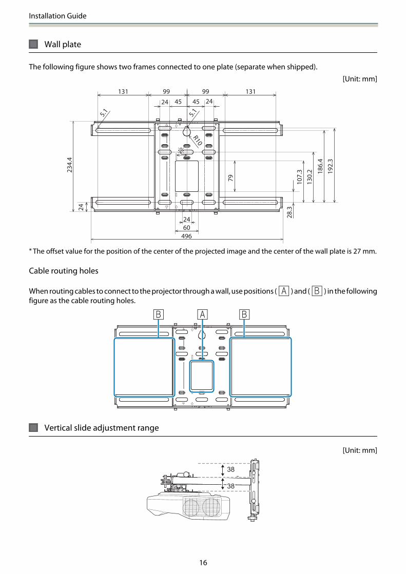
The following figure shows two frames connected to one plate (separate when shipped).
[Unit: mm]
186.
4
130.
210
7.3
28.3
4545 2424
131131 99 99
79
192.
3
234.
4
24
6024
496
5.1 5.1
R10
* The offset value for the position of the center of the projected image and the center of the wall plate is 27 mm.
Cable routing holes
When routing cables to connect to the projector through a wall, use positions ( ) and ( ) in the followingfigure as the cable routing holes.
Vertical slide adjustment range
[Unit: mm]

Installation Guide
17
Horizontal slide adjustment range
[Unit: mm]
Forward/backward slide adjustment range
Arm slide adjustment range
[Unit: mm]
263
Adjustment range for 3-axis adjustment unit installation position
[Unit: mm]

Installation Guide
18
Position for installing accessories
These screw holes allow you to secure peripheral devices and accessories such as external tuners. Usecommercially available M4 screws.
[Unit: mm]
2 x M4
30.549.7
60.8
35
Control Pad/Pen Stand
Control Pad (external dimensions/weight)
[Unit: mm]
153.
5
107
15.4
7
135.9
111
3.511.5109.5
63.3
29 30.9
4 x M4
47
51.5
• Weight: approx. 262 g• Operating temperature: 0 to +50°C (no condensation)• Operating temperature: -20 to +60°C (no condensation)
Installation Guide
19
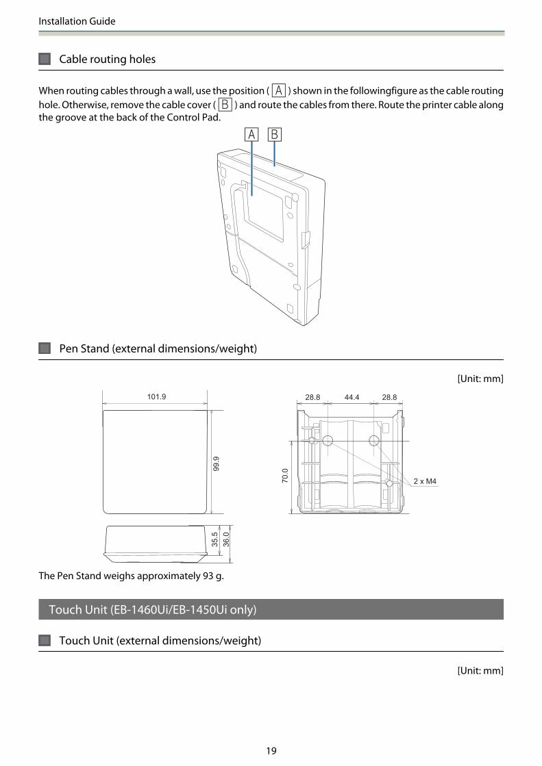
Cable routing holes
When routing cables through a wall, use the position ( ) shown in the followingfigure as the cable routinghole. Otherwise, remove the cable cover ( ) and route the cables from there. Route the printer cable alongthe groove at the back of the Control Pad.
Pen Stand (external dimensions/weight)
[Unit: mm]
99.9
70.0
101.9 44.428.8 28.8
35.5
36.0
2 x M4
The Pen Stand weighs approximately 93 g.
Touch Unit (EB-1460Ui/EB-1450Ui only)
Touch Unit (external dimensions/weight)
[Unit: mm]

Installation Guide
20
The Touch Unit weighs approximately 450 g.
Touch Unit Bracket (external dimensions/adjustment range/weight)
Top
[Unit: mm]229.8
228
57 62
Front
[Unit: mm]
101
104.
8
Installation plate (front)
[Unit: mm]
90
Ø4.2
2-5.7
2-4.
5
90
56
74

Installation Guide
21
When the Touch Unit is installed (side)
[Unit: mm]
100.8
30
Touch Unit Bracket weights approximately 750 g.
Attached labels
The Touch Unit is a Class 1 laser product that conforms to the IEC/EN60825-1:2007 standard.
There are warning labels affixed to the Touch Unit to indicate that it is a Class 1 laser product.
The labels contain the following information.
• Class 1 laser product• Warning: Do not open the case. The device contains a high power laser product.• Warning:
• Caution: If this section is opened, class 3B invisible laser radiation will be emitted.• Avoid exposure to the radiation beams.
Laser diffusion port
The laser beam is diffused from the laser diffusion ports at the back of the Touch Unit.

Installation Guide
22

Installation Guide
23
Projection Distance Table
Figures of Installation Dimensions
To find the appropriate projection distance, see the following figures when installing. The values are onlyrough estimates.
The recommended range for the projection distance (a) is 62 to 244 mm.
The offset value for the position of the center of the projected image and the center of the wall plate is 27 mm.
[Unit: mm]
: Projected image size : Wall plate
: Minimum projection distance (Wide: maxi-mum zoom)to maximum (Tele: minimum zoom)
: Screen
: Numbers on the arm slide scale
: Distance from the top of the projected imageto the bottom wall plate installation screwhole
: Distance from the top of the projected imageto the wall plate temporary securing screwhole
: Height of projected image
: Distance from surface of screen to wall (100mm or less)
Aspect ratio for standard projected image

Installation Guide
24
When installing the Touch Unit (EB-1460Ui/EB-1450Ui only)
By using the supplied Touch Unit Bracket, you can install the Touch Unit outside the whiteboard.
When installing the Touch Unit outside the whiteboard, measure the length from the surface where the TouchUnit is installed to the whiteboard surface ((f) in the following figure).
• When (f) is 20 to 50 mm, you can install the Touch Unit outside the whiteboard using the bracket.• When (f) is less than 20 mm or more than 50 mm install the Touch Unit on the whiteboard.• When the thickness of the top of the frame (e) is 3 mm or more, install the Touch Unit on the whiteboard.
Caution
Install the bottom edge of the Touch Unit so that it is 25 to 100 mm from the top edge of the projected image.
If there are obstacles between the projected image and the Touch Unit such as cables, whiteboard trays,or holders, the Touch Unit will not operate correctly.
When the Touch Unit is installed outside the whiteboard (using the Touch Unit Bracket)
[Unit: mm]

Installation Guide
25
cIf there are any obstacles such as a frame or tray at the bottom of the screen, touch operations willnot operate correctly. Stick the supplied infrared deflectors along the locations of the obstacles(s p.52). Make sure there is a space of approximately 20 mm between the place where the infrareddeflector is stuck and the bottom of the projected image.
When installing the Touch Unit on the whiteboard (without using the Touch Unit Bracket)
You need to leave at least 120 mm distance between the top edge of the projected image and the top edgeof the actual screen.
[Unit: mm]

Installation Guide
26
c• If there are any obstacles such as a frame or tray at the bottom of the screen, touch operations will not
operate correctly. Stick the supplied infrared deflectors over the locations of the obstacles (s p.52).Make sure there is a space of at least 20 mm between the place where the infrared deflector is stuckand the bottom of the projected image.
• If there are obstacles in the shaded areas in the following figure, such as cables, whiteboard trays,holders, or a thick frame, touch operations will not operate correctly.

Installation Guide
27
When installing the Control Pad and the Pen Stand
When installing the Control Pad, leave enough space around it to install/remove the cover or to connect/disconnect cables easily as shown in the following figure.
[Unit: mm]
When installing the Pen Stand next to the Control Pad, do not install it so that it covers the groove in the frontcover as shown in the following figure.
cWhen installing the Touch Unit, do not install the Control Pad on the projection screen and thesurrouding area (shaded area in the following figure). Otherwise The Touch Unit will not operatecorrectly.
[Unit: mm]

Installation Guide
28
When Projected Image is Smaller than 85 Inches
Mount the 3-axis adjustment unit at the position marked with a stamp ( ).
The projection distance table provides the figures when mounting the 3-axis adjustment unit at the positionmarked with a stamp ( ).
The distance from the top of the projected image to the bottom wall plate installation screw hole (c) is thenumber given when the vertical slide is set to the standard position ( ).
Match the notch on the setting plate to the position of the stamp on the wall plate.

Installation Guide
29
16:10 projected image
[Unit: cm]
S
Projected image size
a
Projection Dis-tance
Minimum(Wide) to Maxi-
mum (Tele)
b
Numbers onthe arm slide
scale
c
Distance tothe bottom
wall plate in-stallation
screw hole
d
Distance fromthe top of theprojected im-
age to the wallplate tempora-
ry securingscrew hole
h
Height ofprojected
image
70" 150.8x94.2 6.2 to 20.8 17.1 to 31.7 21.4 40.6 94.3
71" 152.9x95.6 6.6 to 21.6 17.5 to 32.5 21.7 40.9 95.6
72" 155.1x96.9 7.2 to 22.4 18.1 to 33.3 22.0 41.2 96.9
73" 157.2x98.3 7.8 to 23.2 18.7 to 34.1 22.3 41.5 98.3
74" 159.4x99.6 8.4 to 24.1 19.3 to 35.0 22.6 41.8 99.6
75" 161.5x101.0 9.0 to 24.9 19.9 to 35.8 22.8 42.0 101.0
76" 163.7x102.3 9.6 to 25.7 20.5 to 36.6 23.1 42.3 102.3
77" 165.9x103.7 10.2 to 26.5 21.1 to 37.4 23.4 42.6 103.7
78" 168.0x105.0 10.8 to 27.3 21.7 to 38.2 23.7 42.9 105.0
79" 170.2x106.3 11.4 to 28.1 22.3 to 39.0 24.0 43.2 106.3
80" 172.3x107.7 12.0 to 29.0 22.9 to 39.9 24.2 43.4 107.7
81" 174.5x109.0 12.6 to 29.8 23.5 to 40.7 24.5 43.7 109.1
82" 176.6x110.4 13.2 to 30.6 24.1 to 41.5 24.8 44.0 110.4
83" 178.8x111.7 13.8 to 31.0 24.7 to 41.9 25.1 44.3 111.7
84" 180.9x113.1 14.4 to 31.0 25.3 to 41.9 25.4 44.6 113.0
Images smaller than 70 inches are not projected correctly.
c• The values are only rough estimates. The value may differ depending on the location where you place
the projector.• When projecting in Tele, the quality of the projected images may decrease.
Installation Guide
30
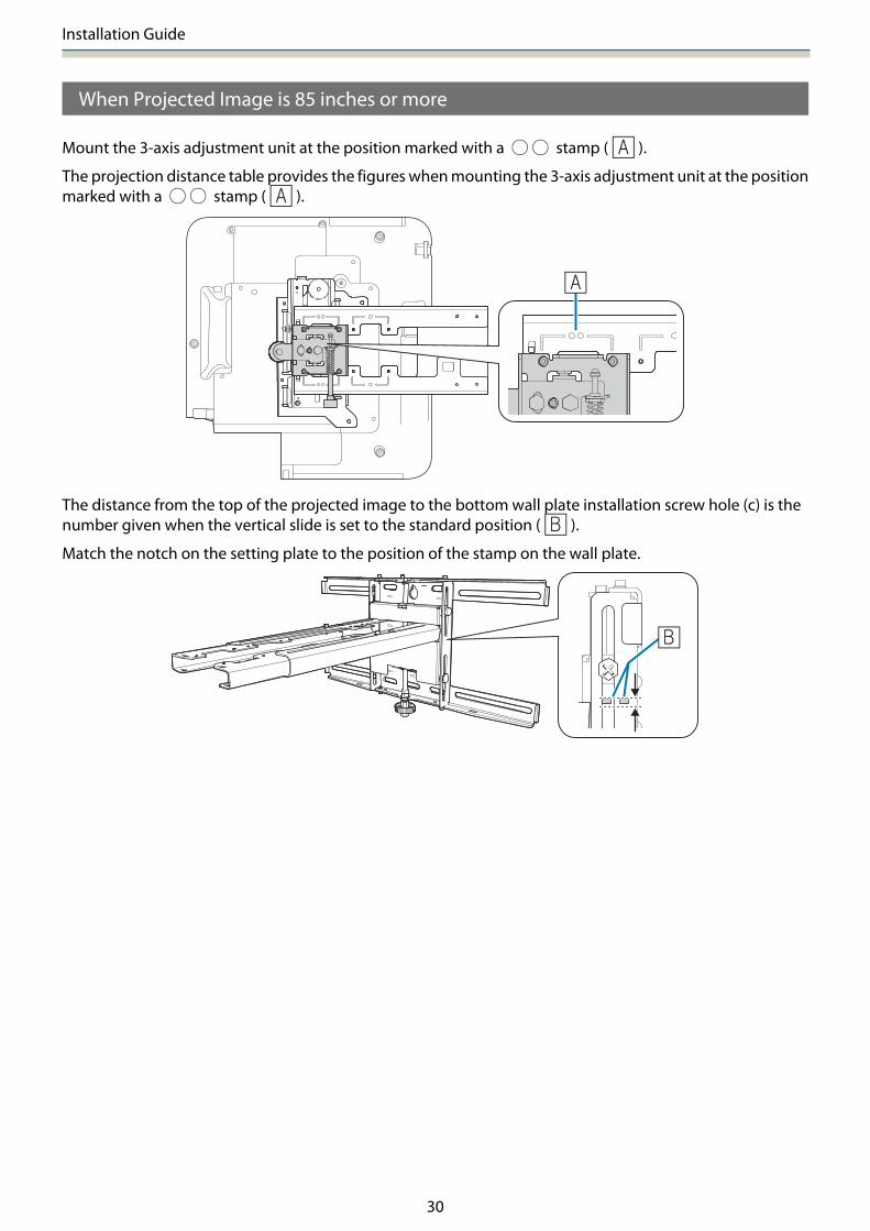
When Projected Image is 85 inches or more
Mount the 3-axis adjustment unit at the position marked with a stamp ( ).
The projection distance table provides the figures when mounting the 3-axis adjustment unit at the positionmarked with a stamp ( ).
The distance from the top of the projected image to the bottom wall plate installation screw hole (c) is thenumber given when the vertical slide is set to the standard position ( ).
Match the notch on the setting plate to the position of the stamp on the wall plate.

Installation Guide
31
16:10 projected image
[Unit: cm]
S
Projected image size
a
ProjectionDistance
Minimum(Wide) toMaximum
(Tele)
b
Numbers onthe arm slide
scale
c
Distance to thebottom wall
plate installa-tion screw hole
d
Distance fromthe top of theprojected im-
age to the wallplate tempora-
ry securingscrew hole
h
Height ofprojected im-
age
85" 183.1x114.4 15.0 to 33.7 17.2 to 35.9 25.6 44.8 114.5
86" 185.2x115.8 15.6 to 34.5 17.8 to 36.7 25.9 45.1 115.8
87" 187.4x117.1 16.2 to 35.3 18.4 to 37.5 26.2 45.4 117.1
88" 189.5x118.5 16.9 to 36.2 19.1 to 38.4 26.5 45.7 118.5
89" 191.7x119.8 17.5 to 37.0 19.7 to 39.2 26.8 46.0 119.8
90" 193.9x121.2 18.1 to 37.9 20.3 to 40.1 27.1 46.3 121.1
91" 196.0x122.5 18.7 to 38.7 20.9 to 40.9 27.3 46.5 122.5
92" 198.2x123.9 19.4 to 39.6 21.6 to 41.8 27.6 46.8 123.9
93" 200.3x125.2 20.0 to 39.7 22.2 to 41.9 27.9 47.1 125.2
94" 202.5x126.5 20.6 to 39.7 22.8 to 41.9 28.2 47.4 126.5
95" 204.6x127.9 21.3 to 39.7 23.5 to 41.9 28.5 47.7 127.8
96" 206.8x129.2 21.9 to 39.7 24.1 to 41.9 28.7 47.9 129.3
97" 208.9x130.6 22.5 to 39.7 24.7 to 41.9 29.0 48.2 130.6
98" 211.1x131.9 23.1 to 39.7 25.3 to 41.9 29.3 48.5 131.9
99" 213.2x133.3 23.8 to 39.7 26.0 to 41.9 29.6 48.8 133.2
100" 215.4x134.6 24.4 to 39.7 26.6 to 41.9 29.9 49.1 134.6
Images larger than 100 inches are not projected correctly.
c• The values are only rough estimates. The value may differ depending on the location where you place
the projector.• When projecting in Tele, the quality of the projected images may decrease.

Installation Guide
32
Installing the Setting Plate
Connecting Devices
Necessary cables
Be sure to prepare the power cord supplied.
Additionally, prepare the necessary cables according to the devices being used.
• USB cable supplied• Touch Unit connection cable supplied (EB-1460Ui/EB-1450Ui only)• Stereo mini cable supplied• Optional computer cables and other cables (prepare according to the connected devices)
For details, see the projector's User's Guide (on the Document CD-ROM).
Necessary cables when using the Easy Interactive Function
When performing mouse operations using the Easy Interactive Function, you need a USB cable. Even whenprojecting using a computer cable, a USB cable is necessary to perform mouse operations.
Necessary cables when installing two projectors in parallel and using the Easy Interactive Function
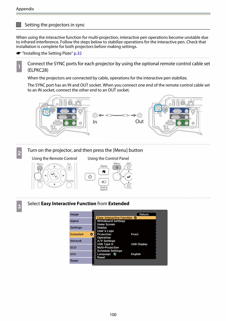
When using the interactive function with two projectors installed in parallel, you need the optional remotecontrol cable set (ELPKC28).
Installation Guide
33
In Out
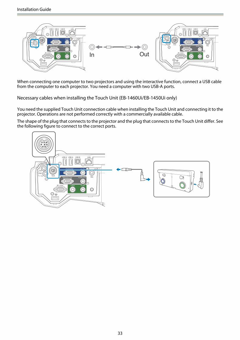
When connecting one computer to two projectors and using the interactive function, connect a USB cablefrom the computer to each projector. You need a computer with two USB-A ports.
Necessary cables when installing the Touch Unit (EB-1460Ui/EB-1450Ui only)
You need the supplied Touch Unit connection cable when installing the Touch Unit and connecting it to theprojector. Operations are not performed correctly with a commercially available cable.
The shape of the plug that connects to the projector and the plug that connects to the Touch Unit differ. Seethe following figure to connect to the correct ports.

Installation Guide
34
Necessary cables when installing the Control Pad
When installing the Control Pad, you need the supplied stereo mini cable that connects the Control Pad tothe projector to supply power to it ( ). Additionally, prepare the necessary cables according to the devicesbeing used.
• When projecting computer images (USB Display), or performing mouse operations usng the Easy Interactive Function,
you need the USB cable supplied ( ).
• When projecting images from a USB storage device, or when saving data to the USB storage device, you need the
USB cable supplied and a commercially available USB storage device ( ).
• When printing the projected image, you need the USB cable supplied ( ) and the USB cable supplied with your
printer ( ).
• When inputing characters with a USB keyboard using the Remote Desktop function, you need the USB cable supplied
( ) and a commercially available USB keyboard ( ).
cThe following Epson projectors can be connected to the Control Pad. Check the rating label on theprojector.
• H727x (where x is any from A to Z)• H771x (where x is any from A to Z)
If you want to connect a different projector or if you have any queries, check the Epson ProjectorContact List provided on the Document CD-ROM and contact your local dealer.

Installation Guide
35
Prepare cables for the connected devices (example)
Document camera
Dedicated USB cable (supplied with document cam-era)
Computer
Computer cable (optional accessory)
External speakers
Audio cable (commercially available)
External monitor
DVI-D cable (commerciallyavailable)
LAN device
LAN cable (commerciallyavailable)

Installation Guide
36
Installation Procedure
Make sure to follow the steps below to install the setting plate. If these steps are not followed, the productcould fall and cause personal injury or property damage.
Warning
Do not use adhesives, lubricants, or oils to install or adjust the setting plate. If you use adhesives to preventthe screws from loosening or things such as lubricants or oils on the slide plate fixing part of the projector,the case may crack and cause the projector to fall, resulting in personal injury or property damage.
Assemble the parts
aConnect the plate and frames (x2) and secure with the M4 x 12 mm bolts (x5) supplied

Installation Guide
37
bCheck that the 3-axis adjustment unit is aligned with the slide plate's standard position( ).
If the standard position ( ) is not correct, loosen the M4 bolt and adjust the position of the slideplate. When you have finished making adjustments, tighten the bolt.
cSecure the 3-axis adjustment unit and the slide plate to the base of the projector with theM4 x 12 mm bolts (x4) supplied
Bolt installation positions
Installation Guide
38
Install the wall plate on the wall
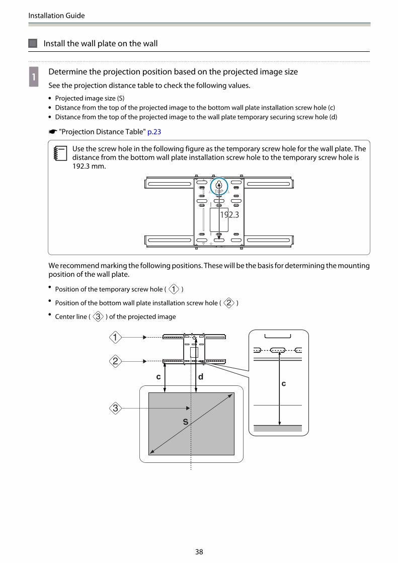
aDetermine the projection position based on the projected image size
See the projection distance table to check the following values.
• Projected image size (S)• Distance from the top of the projected image to the bottom wall plate installation screw hole (c)• Distance from the top of the projected image to the wall plate temporary securing screw hole (d)
s "Projection Distance Table" p.23
cUse the screw hole in the following figure as the temporary screw hole for the wall plate. Thedistance from the bottom wall plate installation screw hole to the temporary screw hole is192.3 mm.
We recommend marking the following positions. These will be the basis for determining the mountingposition of the wall plate.
• Position of the temporary screw hole ( )
• Position of the bottom wall plate installation screw hole ( )
• Center line ( ) of the projected image

Installation Guide
39
bAttach the template sheet to the wall• Match the center line ( ) checked in step 1 to the Image Center B line on the template sheet.
Confirm where the beams are within the wall, and shift the position left or right as necessary.(The position can be shifted horizontally left or right from the center line of the projection surface up to amaximum of 45 mm.)
• Match the height ( ) and ( ) checked in step 1 to the lines on the template sheet.
[Unit: mm]
cDrive a commercially available M10 screw into the position of the temporary screw holefor the wall plate
Leave a gap of 6 mm or more between the wall and the screw head.
dDetermine the positions for the mounting holes for the wall plate
From the screw holes shown in the figure below, secure at least four points for optimum balance.
Installation Guide
40
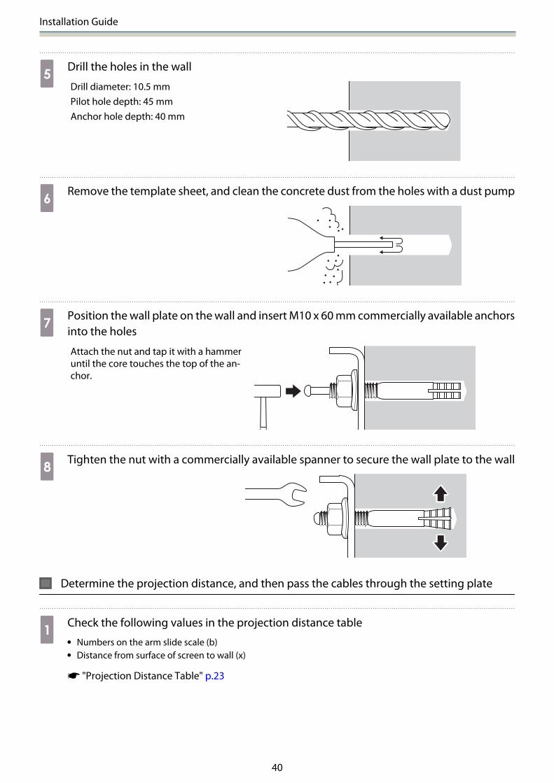
eDrill the holes in the wall
Drill diameter: 10.5 mmPilot hole depth: 45 mmAnchor hole depth: 40 mm
fRemove the template sheet, and clean the concrete dust from the holes with a dust pump
gPosition the wall plate on the wall and insert M10 x 60 mm commercially available anchorsinto the holes
Attach the nut and tap it with a hammeruntil the core touches the top of the an-chor.
hTighten the nut with a commercially available spanner to secure the wall plate to the wall
Determine the projection distance, and then pass the cables through the setting plate
aCheck the following values in the projection distance table• Numbers on the arm slide scale (b)• Distance from surface of screen to wall (x)
s "Projection Distance Table" p.23

Installation Guide
41
bLoosen the M4 x 12 mm bolts (x2) and extend the arm slide on the setting plate
Align the slider with the combined distances of (b) and (x) that you checked in step 1.
cRoute the necessary cables through the setting plate
See the following figure to route the cables so that the ends of the cables that connect to the projectorare on the projector's interface side.
Warning
Do not hang the rest of the cable over the setting plate. They could fall and cause an accident.
c• Route the Touch Unit connection cable through the setting plate (EB-1460Ui/EB-1450Ui only).
Route the cable so that the end that connects to the Touch Unit appears from the lower part ofthe setting plate.
• Route the Control Pad connection cable through the setting plate (EB-1460Ui/EB-1450Ui only).

Installation Guide
42
Attaching the setting plate to the wall plate
aInsert the hexagonal axis into the setting plate
bMount the setting plate to the wall plate
Insert the top of the hexagonal axis into the wall plate, and then insert it into the slot at the bottom.
Caution
• Do not wire the Touch Unit connection cable into the wall (EB-1460Ui/EB-1450Ui only). If it is wiredinto the wall, it cannot be connected to the Touch Unit.
• Take care not to trap the cables between the setting plate and wall plate.
Installation Guide
43
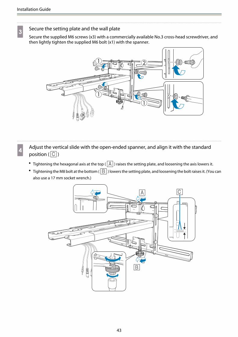
cSecure the setting plate and the wall plate
Secure the supplied M6 screws (x3) with a commercially available No.3 cross-head screwdriver, andthen lightly tighten the supplied M6 bolt (x1) with the spanner.
dAdjust the vertical slide with the open-ended spanner, and align it with the standardposition ( )
• Tightening the hexagonal axis at the top ( ) raises the setting plate, and loosening the axis lowers it.• Tightening the M8 bolt at the bottom ( ) lowers the setting plate, and loosening the bolt raises it. (You can
also use a 17 mm socket wrench.)

Installation Guide
44
eTighten the M6 bolt (x1) to fix the setting plate in position
Securing the projector to the setting plate
aLoosen the screws (x2) and remove the cable cover from the projector

Installation Guide
45
bAttach the 3-axis adjustment unit to the setting plate with the M4 x 12 mm bolts (x4)supplied• When a projected image is smaller than 85 inches: Mount the unit at the stamp ( ).• When a projected image is 85 inches or more: Mount the unit at the stamp ( ).
: Smaller than 85 inches : 85 inches or more
Installation Guide
46
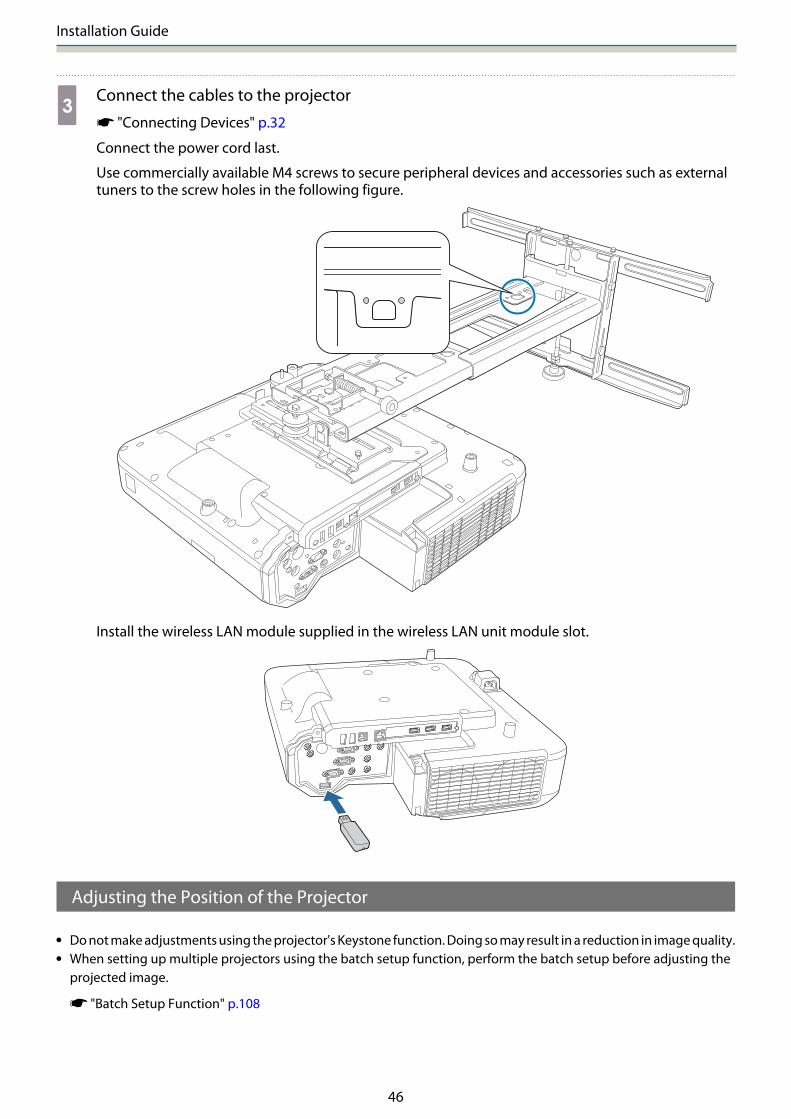
cConnect the cables to the projector
s "Connecting Devices" p.32
Connect the power cord last.
Use commercially available M4 screws to secure peripheral devices and accessories such as externaltuners to the screw holes in the following figure.
Install the wireless LAN module supplied in the wireless LAN unit module slot.
Adjusting the Position of the Projector
• Do not make adjustments using the projector's Keystone function. Doing so may result in a reduction in image quality.• When setting up multiple projectors using the batch setup function, perform the batch setup before adjusting the
projected image.
s "Batch Setup Function" p.108

Installation Guide
47
cWhen installing the Touch Unit (EB-1460Ui/EB-1450Ui only), if there are any obstacles at the bottomof the whiteboard such as a frame or trays, stick the infrared deflectors along the bottom edge ofthe whiteboard before adjusting the projector.
s "Sticking the infrared deflectors (EB-1460Ui/EB-1450Ui only)" p.52
aPress the [Power] button on the remote control or the control panel to turn on the projector
Using the Remote Control Using the Control Panel
Caution
While projecting, do not put your face or hands near the air exhaust vent, and do not place objectsthat may become warped or damaged by heat near the vent. Hot air from the air exhaust vent couldcause burns, warping, or accidents to occur.
bOpen the air filter cover, and then adjust the focus using the focus lever
Fine-tune the focus later.
After you finish making adjustments, close the air filter cover.
c• You can change the display language from Language on the Extended menu.
s Projector's User's Guide - Projector menu• When you turn on the projector for the first time, the message "Do you want to set the
time?" is displayed. If you set it later, select No.

Installation Guide
48
cChange the aspect ratio of the projected image (only when necessary)
Project images from a connected device, and then press the [Aspect] button on the remote control.
Each time you press the button, the aspect name is displayed on the screen and the aspect ratiochanges.
Using the Remote Control
c• For details on connecting to devices and projecting images, see the Quick Start Guide.• The aspect ratio does not change when no images are being projected from the connected
device.• You can also change the aspect ratio from Aspect from the Signal menu.
s Projector's User's Guide - Projector menu
dPress the projector's [Menu] button.
Using the Remote Control Using the Control Panel
eSelect Installation Guide from Settings
The guidance screen is displayed.

Installation Guide
49
fAfter loosening the adjustment dial at the bottom, adjust the horizontal roll using theadjustment dial at the top.
cRepeat steps 6 to 11 as necessary.
After you finish making adjustments, tighten the adjustment dial at the bottom.
gLoosen the M4 screw (x1) with the hexagon wrench, and then adjust the horizontal rotationwith the adjustment dial
After you finish making adjustments, tighten the M4 screws that you loosened.
Installation Guide
50
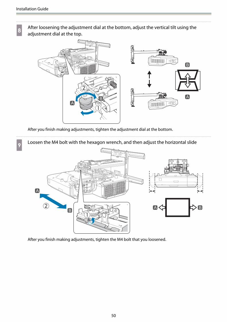
hAfter loosening the adjustment dial at the bottom, adjust the vertical tilt using theadjustment dial at the top.
After you finish making adjustments, tighten the adjustment dial at the bottom.
iLoosen the M4 bolt with the hexagon wrench, and then adjust the horizontal slide
After you finish making adjustments, tighten the M4 bolt that you loosened.

Installation Guide
51
jLoosen the M4 bolts (x2) with the hexagon wrench, and then adjust the forward/backwardslide
After you finish making adjustments, tighten the M4 bolts that you loosened.
kLoosen the M6 bolt (x1) with the open-ended spanner, and then adjust the vertical slide
Adjust the vertical slide with the hexagonal axis at the top or the bottom.
• Tightening the hexagonal axis at the top raises the setting plate, and loosening the axis lowers it.• Tightening the M8 bolt at the bottom lowers the setting plate, and loosening the bolt raises it. (You can also
use a 17 mm socket wrench.)
After you finish making adjustments, tighten the M6 bolt that you loosened.
Installation Guide
52
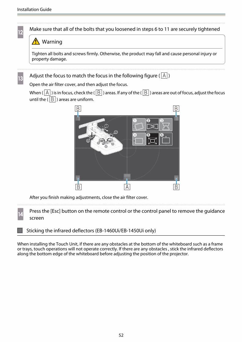
lMake sure that all of the bolts that you loosened in steps 6 to 11 are securely tightened
Warning
Tighten all bolts and screws firmly. Otherwise, the product may fall and cause personal injury orproperty damage.
mAdjust the focus to match the focus in the following figure ( )
Open the air filter cover, and then adjust the focus.
When ( ) is in focus, check the ( ) areas. If any of the ( ) areas are out of focus, adjust the focusuntil the ( ) areas are uniform.
After you finish making adjustments, close the air filter cover.
nPress the [Esc] button on the remote control or the control panel to remove the guidancescreen
Sticking the infrared deflectors (EB-1460Ui/EB-1450Ui only)
When installing the Touch Unit, if there are any obstacles at the bottom of the whiteboard such as a frameor trays, touch operations will not operate correctly. If there are any obstacles , stick the infrared deflectorsalong the bottom edge of the whiteboard before adjusting the position of the projector.

Installation Guide
53
c• Do not remove an infrared deflector once it has been stuck in place. This can weaken the adhesive
strength of the tape.• Do not stick tape or place anything on the infrared deflectors. The infrared deflector will not function
correctly.
Arc Correction
When fine-tuning the shape of the projected image, perform Arc Correction.
aTurn on the projector, and then press the [Menu] button
Using the Remote Control Using the Control Panel
bSelect Geometry Correction from Settings
Installation Guide
54
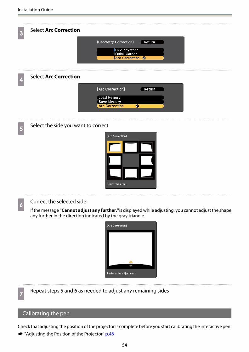
cSelect Arc Correction
dSelect Arc Correction
eSelect the side you want to correct
fCorrect the selected side
If the message "Cannot adjust any further."is displayed while adjusting, you cannot adjust the shapeany further in the direction indicated by the gray triangle.
gRepeat steps 5 and 6 as needed to adjust any remaining sides
Calibrating the pen
Check that adjusting the position of the projector is complete before you start calibrating the interactive pen.
s "Adjusting the Position of the Projector" p.46
Installation Guide
55
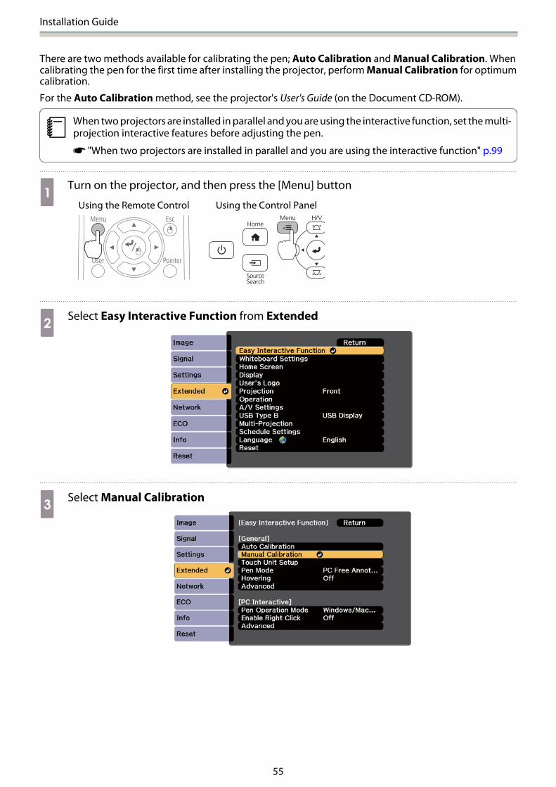
There are two methods available for calibrating the pen; Auto Calibration and Manual Calibration. Whencalibrating the pen for the first time after installing the projector, perform Manual Calibration for optimumcalibration.
For the Auto Calibration method, see the projector's User's Guide (on the Document CD-ROM).
cWhen two projectors are installed in parallel and you are using the interactive function, set the multi-projection interactive features before adjusting the pen.
s "When two projectors are installed in parallel and you are using the interactive function" p.99
aTurn on the projector, and then press the [Menu] button
Using the Remote Control Using the Control Panel
bSelect Easy Interactive Function from Extended
cSelect Manual Calibration

Installation Guide
56
dCheck that the screen is in focus, and then select Yes
A green dot is displayed at the top left of the projection screen.
eTouch the center of the dot with the pen tip of the interactive pen
The dot disappears and moves to the next position.
cMake sure you touch the center of the dot. Otherwise, it may not be positioned correctly.

Installation Guide
57
fRepeat step 5 until all of the dots disappear
The dot appears at the top left first and then moves towards the bottom right.
When all of the dots disappear, calibration is complete.
c• Check that there are no obstacles between the interactive pen and the Interactive pen
receiver ( ).
• If you touch the wrong position, press the [Esc] button on the remote control to return to theprevious dot.
• To cancel calibration, hold down the [Esc] button for two seconds.
Installation Guide
58
Attaching the Covers
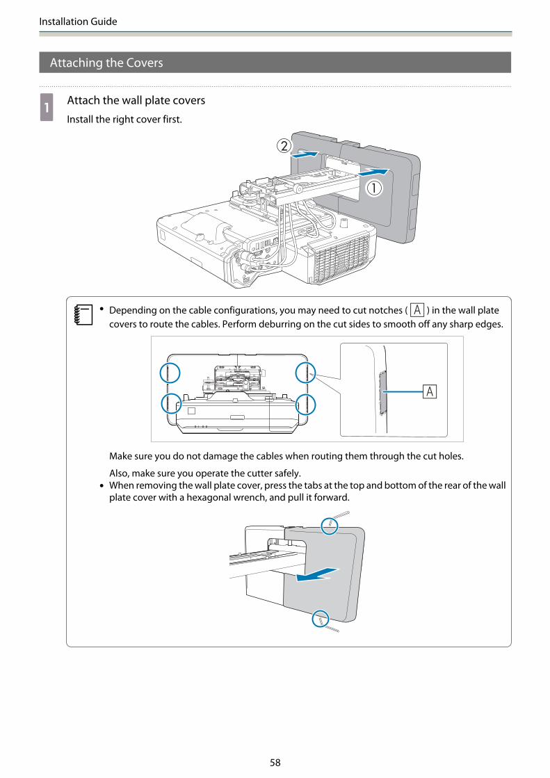
aAttach the wall plate covers
Install the right cover first.
c• Depending on the cable configurations, you may need to cut notches ( ) in the wall plate
covers to route the cables. Perform deburring on the cut sides to smooth off any sharp edges.
Make sure you do not damage the cables when routing them through the cut holes.
Also, make sure you operate the cutter safely.• When removing the wall plate cover, press the tabs at the top and bottom of the rear of the wall
plate cover with a hexagonal wrench, and pull it forward.
Installation Guide
59
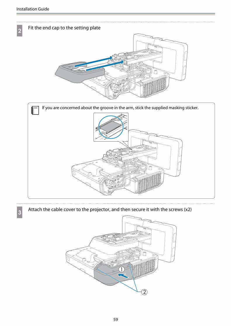
bFit the end cap to the setting plate
cIf you are concerned about the groove in the arm, stick the supplied masking sticker.
cAttach the cable cover to the projector, and then secure it with the screws (x2)
Installation Guide
60
Caution
Only a specialist should remove or reinstall the projector, including for maintenance and repairs. See theprojector's User's Guide for instructions on maintenance and repairs.
Warning
• Never loosen the bolts and nuts after installation. Confirm that the screws have not become loose on a regularbasis. If you find any loose screws, tighten them firmly. Otherwise, the product may fall and cause personalinjury or property damage.
• Do not hang on this product or hang a heavy object on this product. If this product falls, it could cause deathor personal injury.
Installation Guide
61
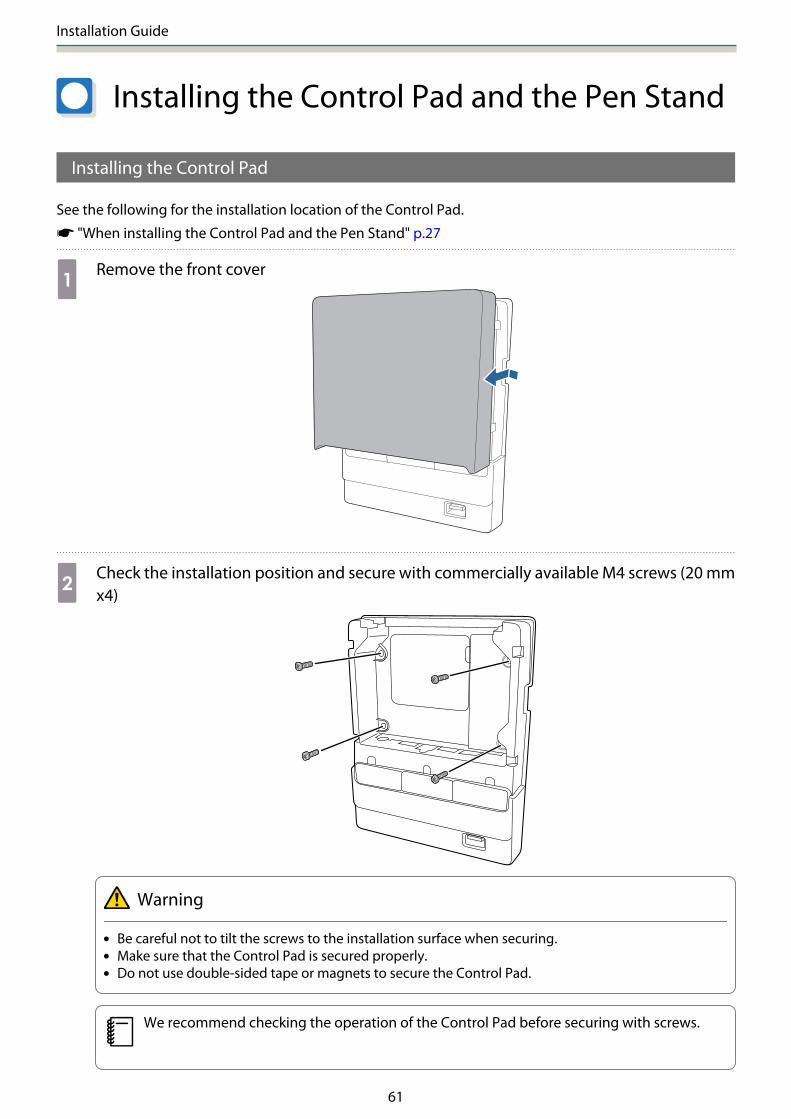
Installing the Control Pad and the Pen Stand
Installing the Control Pad
See the following for the installation location of the Control Pad.
s "When installing the Control Pad and the Pen Stand" p.27
aRemove the front cover
bCheck the installation position and secure with commercially available M4 screws (20 mmx4)
Warning
• Be careful not to tilt the screws to the installation surface when securing.• Make sure that the Control Pad is secured properly.• Do not use double-sided tape or magnets to secure the Control Pad.
cWe recommend checking the operation of the Control Pad before securing with screws.

Installation Guide
62
cConnect the cable that is connected to the projector to the Control Pad
For details on connecting cables, see the following.
s "Necessary cables when installing the Control Pad" p.34
dPaste the port protection stickers supplied to the plugs on the Control Pad that are notbeing used
s "Control Pad" p.13
eAttach the front cover
Installing the Pen Stand
See the following for the installation location of the Pen Stand.
s "When installing the Control Pad and the Pen Stand" p.27
aRemove the front cover

Installation Guide
63
bCheck the installation position and secure with commercially available M4 screws (20 mmx2)
Warning
• Be careful not to tilt the screw to the installation surface when securing.• Make sure that the Pen Stand is secured properly.• Do not use double-stick tapes or magnets to secure the Pen Stand.
cAttach the cover
Installation Guide
64
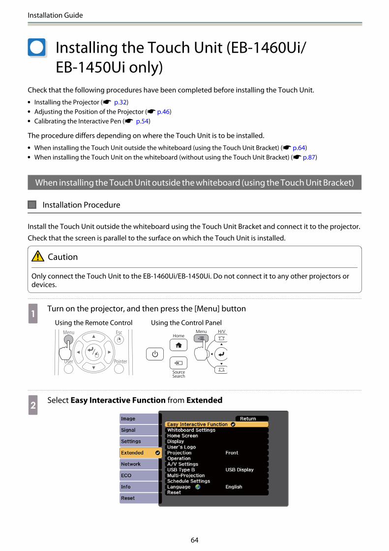
Installing the Touch Unit (EB-1460Ui/EB-1450Ui only)
Check that the following procedures have been completed before installing the Touch Unit.
• Installing the Projector (s p.32)• Adjusting the Position of the Projector (s p.46)• Calibrating the Interactive Pen (s p.54)
The procedure differs depending on where the Touch Unit is to be installed.
• When installing the Touch Unit outside the whiteboard (using the Touch Unit Bracket) (s p.64)• When installing the Touch Unit on the whiteboard (without using the Touch Unit Bracket) (s p.87)
When installing the Touch Unit outside the whiteboard (using the Touch Unit Bracket)
Installation Procedure
Install the Touch Unit outside the whiteboard using the Touch Unit Bracket and connect it to the projector.
Check that the screen is parallel to the surface on which the Touch Unit is installed.
Caution
Only connect the Touch Unit to the EB-1460Ui/EB-1450Ui. Do not connect it to any other projectors ordevices.
aTurn on the projector, and then press the [Menu] button
Using the Remote Control Using the Control Panel
bSelect Easy Interactive Function from Extended

Installation Guide
65
cSelect Touch Unit Setup
dSelect Installation Pattern
The installation pattern is displayed on the projected image.
eLoosen the screw at the bottom of the dial cover using a commercially available No.2 cross-head screwdriver

Installation Guide
66
fSlide the dial cover down to remove it
gDetermine the installation position for the Touch Unit Bracket
We recommend marking the following installation positions (positions of the screw holes) to makeinstallation easier.
( ): Center line of installation pattern. Align with the center line ( ) of the installation plate.
( ): 25 to 100 mm from the top edge (white line) of the projected image. Align with the bottom lineof the installation plate.
[Unit: mm]
25-100mm
Installation Guide
67
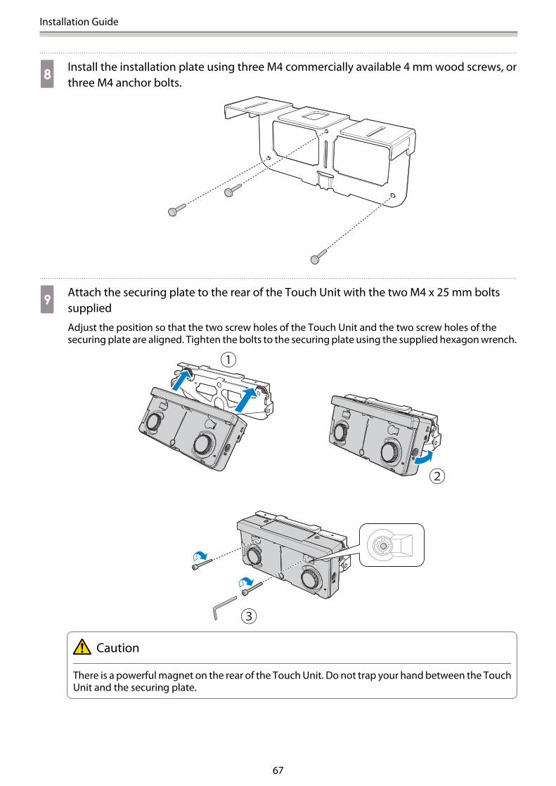
hInstall the installation plate using three M4 commercially available 4 mm wood screws, orthree M4 anchor bolts.
iAttach the securing plate to the rear of the Touch Unit with the two M4 x 25 mm boltssupplied
Adjust the position so that the two screw holes of the Touch Unit and the two screw holes of thesecuring plate are aligned. Tighten the bolts to the securing plate using the supplied hexagon wrench.
Caution
There is a powerful magnet on the rear of the Touch Unit. Do not trap your hand between the TouchUnit and the securing plate.

Installation Guide
68
jUse the supplied M4 x 12 mm bolts (x2) to install the securing plate on the installation plate
Tighten the bolts to the securing plate using the supplied hexagon wrench.
kMeasure the distance from the wall to the surface of the screen (f)
lAdjust the height of the left and right according to the value (f) measured in step 11
Loosen the two screws and move the Touch Unit back and forth to adjust the left and right so that thearrow aligns with the value on the scale the same as (f). When you have finished adjusting, tighten thetwo screws.

Installation Guide
69
mSecure the Touch Unit and the installation plate with the hexagon socket head cap bolt
The bolt used varies according to the distance (f) from the wall to the surface of the screen measuredin step 11. Tighten the bolt to the installation plate using the supplied hexagon wrench.
When (f) = 20 to 35 mm: M4 x 55 mm bolt
When (f) = 35 to 50 mm: M4 x 70 mm bolt
nConnect the Touch Unit connection cable that is connected to the projector to the TCHport on the Touch Unit
Angle Adjustment
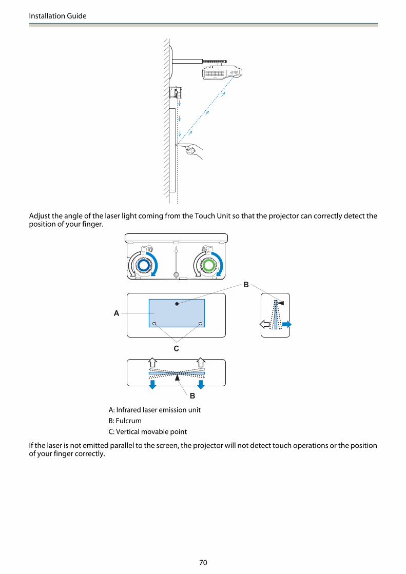
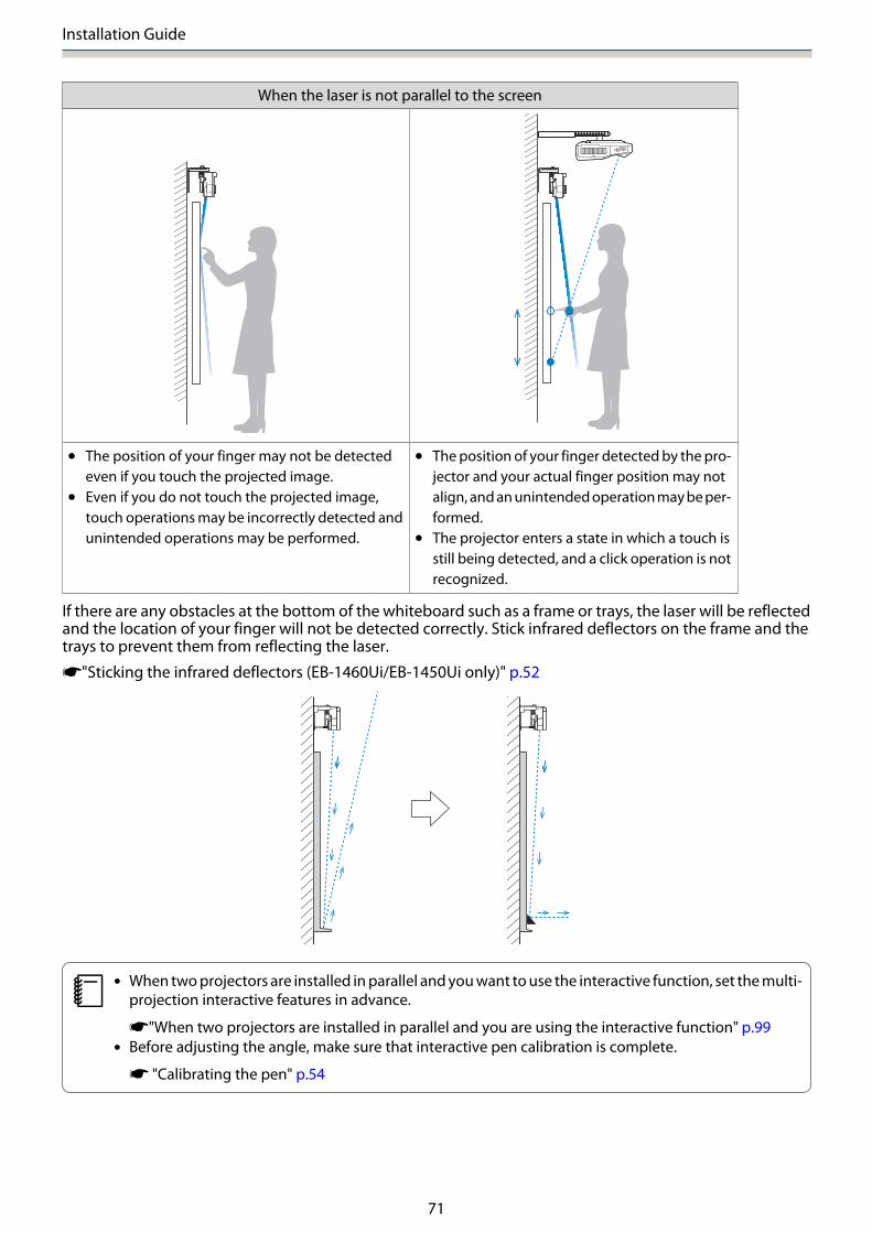
An infrared laser in the shape of a curtain is emitted from the Touch Unit. The infrared laser reflects off yourfinger when touched to the whiteboard thereby detecting the finger position allowing the projector's infraredcamera to recognize the position being reflected.
Installation Guide
70
Adjust the angle of the laser light coming from the Touch Unit so that the projector can correctly detect theposition of your finger.
A
C
B
B
A: Infrared laser emission unitB: FulcrumC: Vertical movable point
If the laser is not emitted parallel to the screen, the projector will not detect touch operations or the positionof your finger correctly.
Installation Guide
71
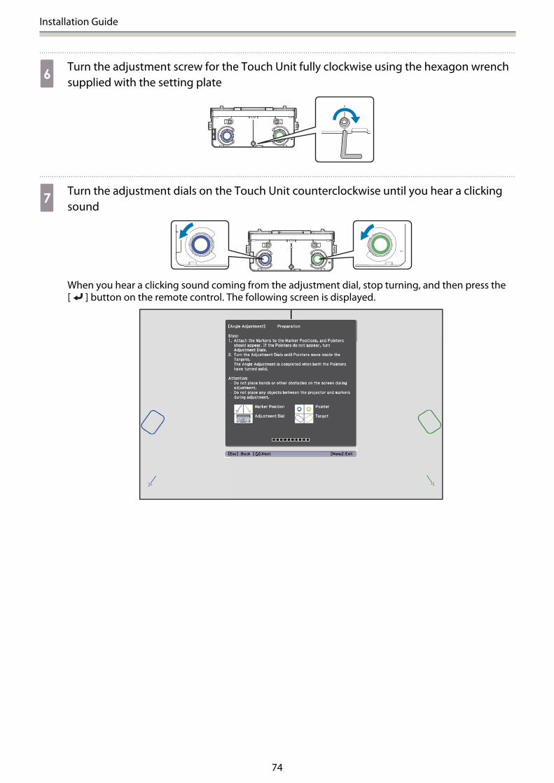
When the laser is not parallel to the screen
• The position of your finger may not be detectedeven if you touch the projected image.
• Even if you do not touch the projected image,touch operations may be incorrectly detected andunintended operations may be performed.
• The position of your finger detected by the pro-jector and your actual finger position may notalign, and an unintended operation may be per-formed.
• The projector enters a state in which a touch isstill being detected, and a click operation is notrecognized.
If there are any obstacles at the bottom of the whiteboard such as a frame or trays, the laser will be reflectedand the location of your finger will not be detected correctly. Stick infrared deflectors on the frame and thetrays to prevent them from reflecting the laser.
s"Sticking the infrared deflectors (EB-1460Ui/EB-1450Ui only)" p.52
c• When two projectors are installed in parallel and you want to use the interactive function, set the multi-
projection interactive features in advance.
s"When two projectors are installed in parallel and you are using the interactive function" p.99• Before adjusting the angle, make sure that interactive pen calibration is complete.
s "Calibrating the pen" p.54

Installation Guide
72
aSelect Easy Interactive Function from the projector's Extended menu
bSelect Touch Unit Setup
cSet Power to On
The Touch Unit power turns on and the indicator is lit blue.
cWhen Power is set to On, the next time the projector is turned on, the Touch Unit automaticallyturns on.

Installation Guide
73
dSelect Angle Adjustment
eSelect Installing the Touch Unit with the bracket
The following screen is displayed.
Installation Guide
74
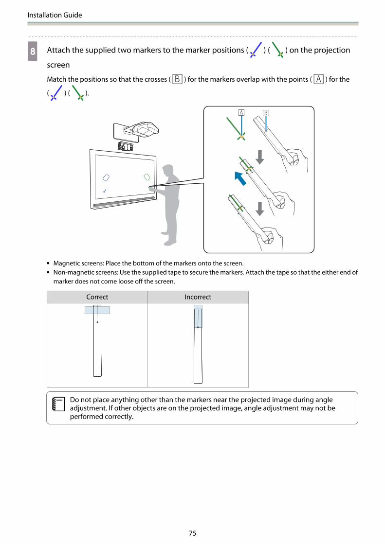
fTurn the adjustment screw for the Touch Unit fully clockwise using the hexagon wrenchsupplied with the setting plate
gTurn the adjustment dials on the Touch Unit counterclockwise until you hear a clickingsound
When you hear a clicking sound coming from the adjustment dial, stop turning, and then press the[ ] button on the remote control. The following screen is displayed.
Installation Guide
75
h Attach the supplied two markers to the marker positions ( ) ( ) on the projection
screen
Match the positions so that the crosses ( ) for the markers overlap with the points ( ) for the
( ) ( ).
• Magnetic screens: Place the bottom of the markers onto the screen.• Non-magnetic screens: Use the supplied tape to secure the markers. Attach the tape so that the either end of
marker does not come loose off the screen.
Correct Incorrect
cDo not place anything other than the markers near the projected image during angleadjustment. If other objects are on the projected image, angle adjustment may not beperformed correctly.

Installation Guide
76
iTurn the adjustment screw on the Touch Unit counterclockwise to display the pointers( ) ( )
Adjusting the angle of the Touch Unit using the adjustment screw
Before adjustment After adjustment
When the pointers overlap in the correct position, the colors become solid ( ) ( ).

Installation Guide
77
Turn the adjustment screw clockwise to move the pointer down as needed.
c• When turning the adjustment screw, make sure shadows from your arm or body do not overlap
with the markers.• If the pointers are not solid colors ( ) ( ), check if the Touch Unit and screen are parallel.
Adjust the Touch Unit Bracket so that the Touch Unit and screen are parallel.
jWhen the pointers on the left and right become solid colors ( ) ( ), press the [ ]button on the remote control
The following screen is displayed.

Installation Guide
78
kTurn the adjustment dials on the Touch Unit to move the pointers ( ) ( ) so that they
overlap with the target ( ) ( ) of the same color on either side
When you turn the adjustment dial clockwise, the pointer moves diagonally up towards the center ofthe projected image.
When you turn the adjustment dial counterclockwise, the pointer moves diagonally down away fromthe center of the projected image.
When the pointers overlap in the correct position, the colors become solid ( ) ( ).
c• If you hear a clicking sound from the dial, the pointer does not move any further.• When turning the dials, make sure shadows from your arm or body do not overlap with the
markers.

Installation Guide
79
lWhen the pointers on the left and right become solid colors ( ) ( ), press the [ ]button on the remote control
The following screen is displayed.
m Place the markers at the top marker positions [1] ( ) ( )
When angle adjustment is performed correctly, the upper pointers become solid colors ( ) ( ).
If the upper pointers do not become solid colors ( ) ( ), start again from step 1.
Installation Guide
80
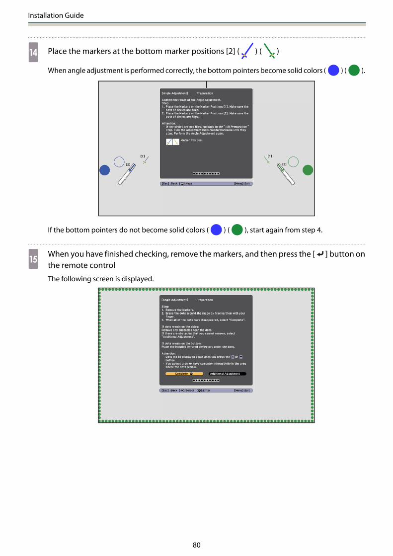
n Place the markers at the bottom marker positions [2] ( ) ( )
When angle adjustment is performed correctly, the bottom pointers become solid colors ( ) ( ).
If the bottom pointers do not become solid colors ( ) ( ), start again from step 4.
oWhen you have finished checking, remove the markers, and then press the [ ] button onthe remote control
The following screen is displayed.
Installation Guide
81
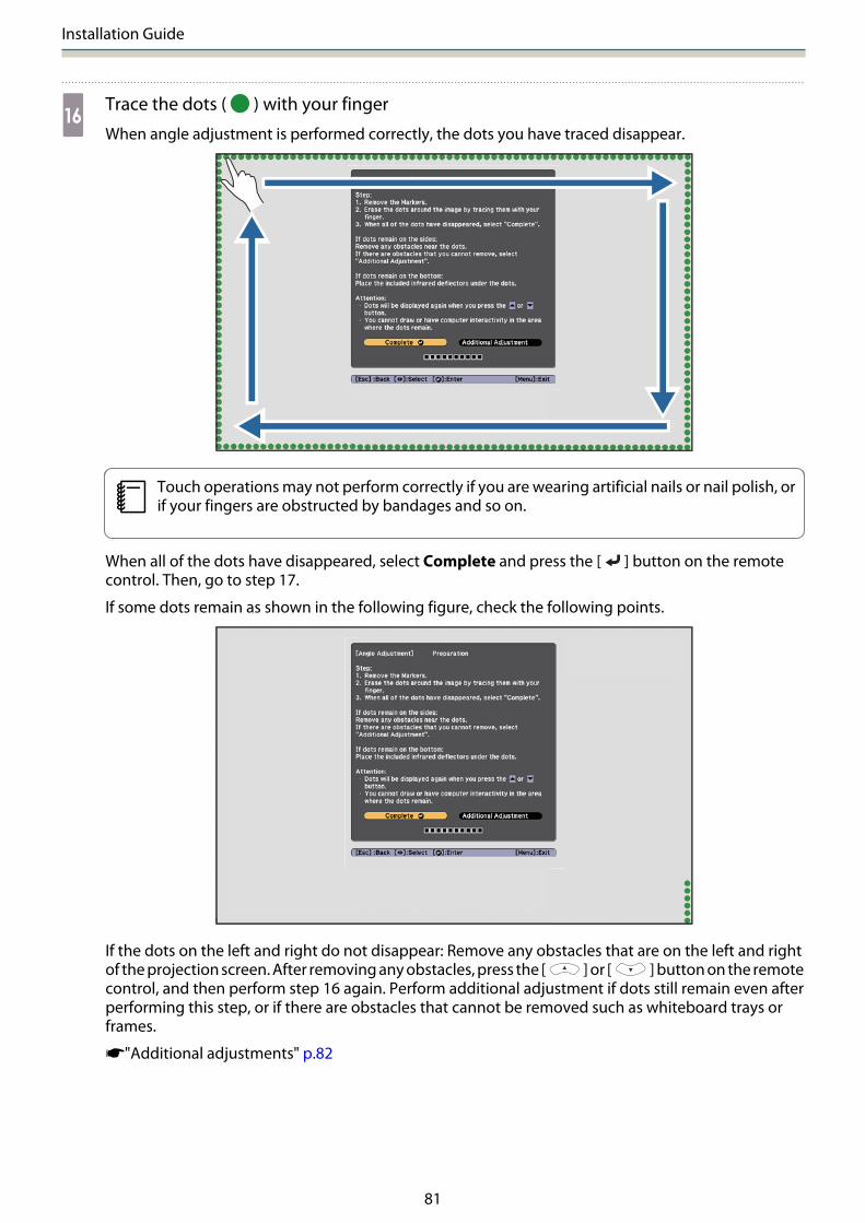
pTrace the dots ( ) with your finger
When angle adjustment is performed correctly, the dots you have traced disappear.
cTouch operations may not perform correctly if you are wearing artificial nails or nail polish, orif your fingers are obstructed by bandages and so on.
When all of the dots have disappeared, select Complete and press the [ ] button on the remotecontrol. Then, go to step 17.
If some dots remain as shown in the following figure, check the following points.
If the dots on the left and right do not disappear: Remove any obstacles that are on the left and rightof the projection screen. After removing any obstacles, press the [ ] or [ ] button on the remotecontrol, and then perform step 16 again. Perform additional adjustment if dots still remain even afterperforming this step, or if there are obstacles that cannot be removed such as whiteboard trays orframes.
s"Additional adjustments" p.82

Installation Guide
82
qAttach the dial cover, and then tighten the screw at the bottom of the dial cover
When you have finished making adjustments, perform a touch calibration.
s"Touch Calibration" p.84
cMake sure you store the markers in a safe place.
Additional adjustments
Perform additional adjustments if the dots on the left and right remain after adjusting the angle.
If the laser crosses the frame of the screen, it reflects within the screen and touch operations cannot beperformed correctly. Additional adjustments adjust the height of the laser beam so that it does not cross theframe on the left and right.

Installation Guide
83
aSelect Additional Adjustment
The following screen is displayed.
After this, adjust using the same procedure for angle adjustment from step 11. Follow the on-screeninstructions to make adjustments.
s"Angle Adjustment" p.69
When you have finished making adjustments, perform a touch calibration.
s"Touch Calibration" p.84
cMake sure you store the markers in a safe place.
Installation Guide
84
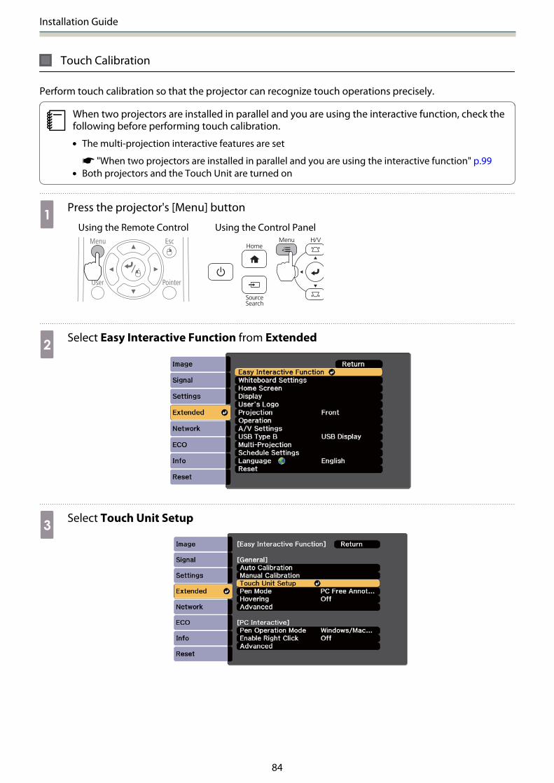
Touch Calibration
Perform touch calibration so that the projector can recognize touch operations precisely.
cWhen two projectors are installed in parallel and you are using the interactive function, check thefollowing before performing touch calibration.
• The multi-projection interactive features are set
s "When two projectors are installed in parallel and you are using the interactive function" p.99• Both projectors and the Touch Unit are turned on
aPress the projector's [Menu] button
Using the Remote Control Using the Control Panel
bSelect Easy Interactive Function from Extended
cSelect Touch Unit Setup

Installation Guide
85
dSelect Touch Calibration
The focus adjustment message is displayed.
eCheck that the screen is in focus, and then select Yes
A dot is displayed at the top left of the projection screen.

Installation Guide
86
fTouch the center of the dot with your finger
When the dot disappears and moves to the next position, remove your finger.
c• Make sure you touch the center of the dot. Otherwise, it may not be positioned correctly.
• Do not touch with anything else except the tip of your finger.
gRepeat step 6 until all of the dots disappear
When all of the dots disappear, touch calibration is complete.
c• If you touch the wrong position, press the [Esc] button on the remote control or control panel.
This returns you to the previous dot. You cannot go back by two dots.• To cancel touch calibration, hold down the [Esc] button for two seconds.• It may take several seconds after all of the dots have disappeared until touch calibration is
complete.

Installation Guide
87
When installing the Touch Unit on the whiteboard (without using the Touch UnitBracket)
About installation
• There are magnets built into the back of the Touch Unit. Normally, the Touch Unit should be installed by attachingthe magnets to the screen.
• If the magnets cannot be attached to a screen, use commercially available M4 screws (x3).• Attach the Touch Unit to the same level surface as the screen surface.
Installation Procedure
Install the Touch Unit, and then connect to the projector.
Caution
Only connect the Touch Unit to the EB-1460Ui/EB-1450Ui. Do not connect it to any other projectors ordevices.
aTurn on the projector, and then press the [Menu] button
Using the Remote Control Using the Control Panel
bSelect Easy Interactive Function from Extended

Installation Guide
88
cSelect Touch Unit Setup
dSelect Installation Pattern
The installation pattern is displayed on the projected image.
eLoosen the screw at the bottom of the dial cover using a commercially available No.2 cross-head screwdriver
Installation Guide
89
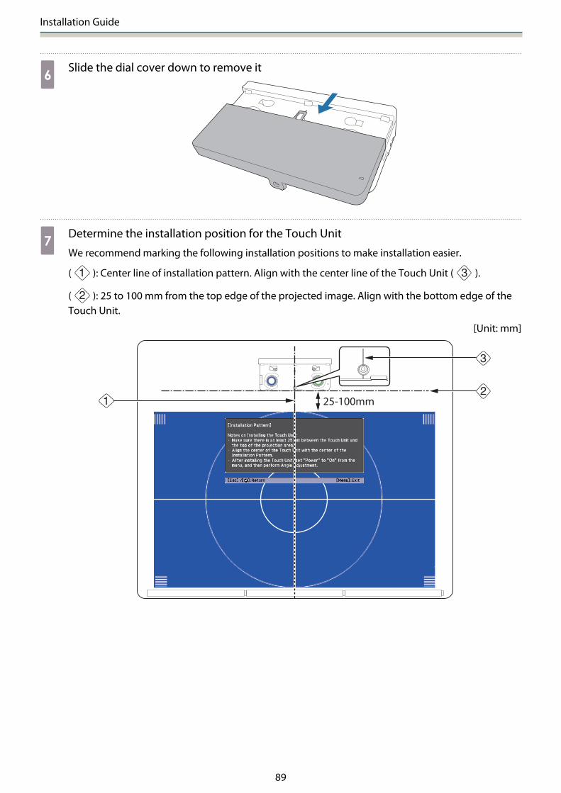
fSlide the dial cover down to remove it
gDetermine the installation position for the Touch Unit
We recommend marking the following installation positions to make installation easier.
( ): Center line of installation pattern. Align with the center line of the Touch Unit ( ).
( ): 25 to 100 mm from the top edge of the projected image. Align with the bottom edge of theTouch Unit.
[Unit: mm]
Installation Guide
90
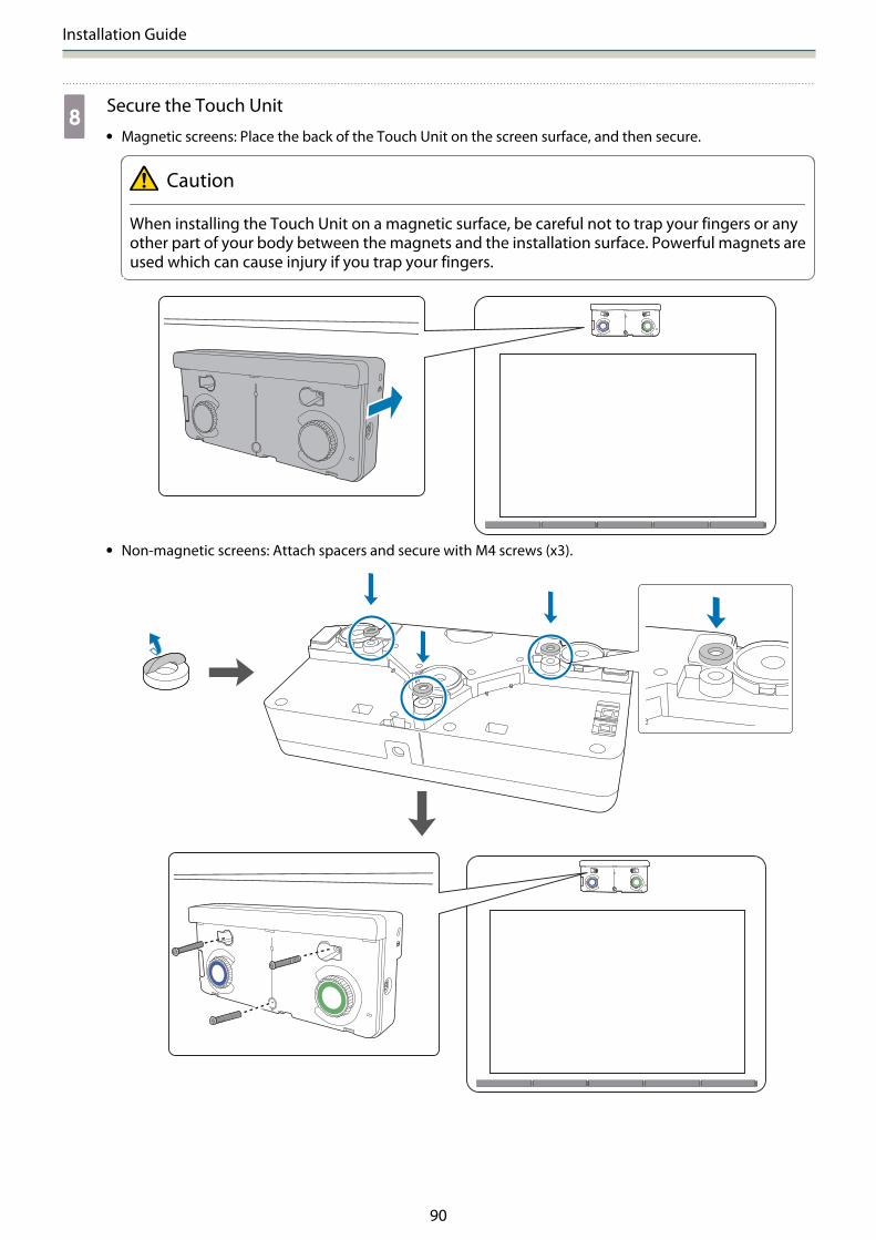
hSecure the Touch Unit• Magnetic screens: Place the back of the Touch Unit on the screen surface, and then secure.
Caution
When installing the Touch Unit on a magnetic surface, be careful not to trap your fingers or anyother part of your body between the magnets and the installation surface. Powerful magnets areused which can cause injury if you trap your fingers.
• Non-magnetic screens: Attach spacers and secure with M4 screws (x3).

Installation Guide
91
[Unit: mm]
Screw hole cross-section
iConnect the Touch Unit connection cable that is connected to the projector to the TCHport on the Touch Unit
Angle Adjustment
This section explains how to adjust the angle of the Touch Unit. For details on angle adjustment, see p.69.
c• When two projectors are installed in parallel and you want to use the interactive function, set the multi-
projection interactive features in advance.
s"Multi-Projection settings" p.95• Before adjusting the angle, make sure that interactive pen calibration is complete.
s "Calibrating the pen" p.54

Installation Guide
92
aSelect Easy Interactive Function from the projector's Extended menu
bSelect Touch Unit Setup
cSet Power to On
The Touch Unit power turns on and the indicator is lit blue.
cWhen Power is set to On, the next time the projector is turned on, the Touch Unit automaticallyturns on.

Installation Guide
93
dSelect Angle Adjustment
Installation Guide
94
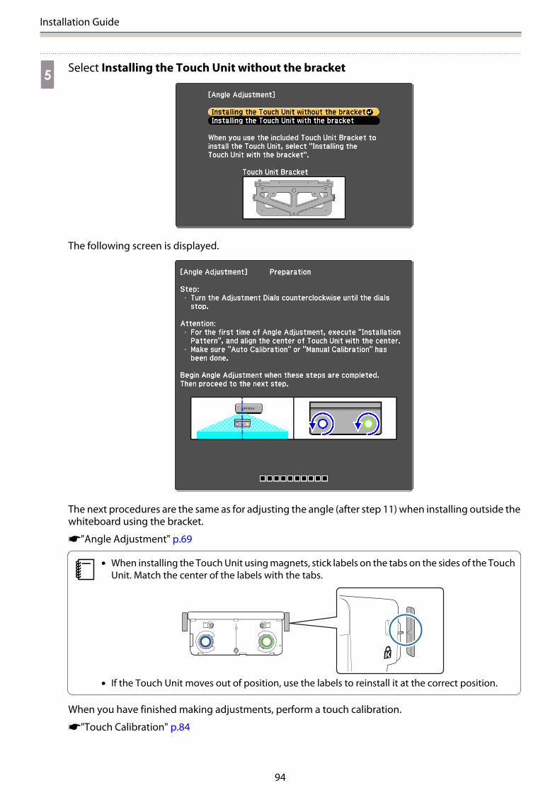
eSelect Installing the Touch Unit without the bracket
The following screen is displayed.
The next procedures are the same as for adjusting the angle (after step 11) when installing outside thewhiteboard using the bracket.
s"Angle Adjustment" p.69
c• When installing the Touch Unit using magnets, stick labels on the tabs on the sides of the Touch
Unit. Match the center of the labels with the tabs.
• If the Touch Unit moves out of position, use the labels to reinstall it at the correct position.
When you have finished making adjustments, perform a touch calibration.
s"Touch Calibration" p.84
Appendix
95
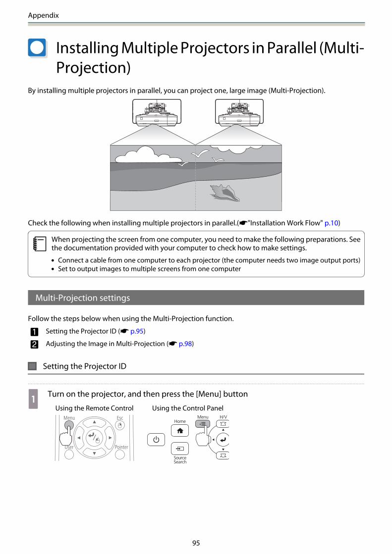
Installing Multiple Projectors in Parallel (Multi-Projection)
By installing multiple projectors in parallel, you can project one, large image (Multi-Projection).
Check the following when installing multiple projectors in parallel.(s"Installation Work Flow" p.10)
cWhen projecting the screen from one computer, you need to make the following preparations. Seethe documentation provided with your computer to check how to make settings.
• Connect a cable from one computer to each projector (the computer needs two image output ports)• Set to output images to multiple screens from one computer
Multi-Projection settings
Follow the steps below when using the Multi-Projection function.
a Setting the Projector ID (s p.95)
b Adjusting the Image in Multi-Projection (s p.98)
Setting the Projector ID
aTurn on the projector, and then press the [Menu] button
Using the Remote Control Using the Control Panel
Appendix
96
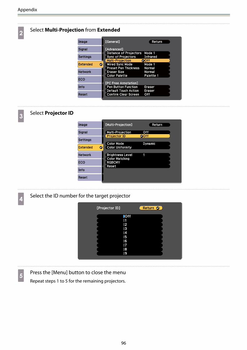
bSelect Multi-Projection from Extended
cSelect Projector ID
dSelect the ID number for the target projector
ePress the [Menu] button to close the menu
Repeat steps 1 to 5 for the remaining projectors.
Appendix
97
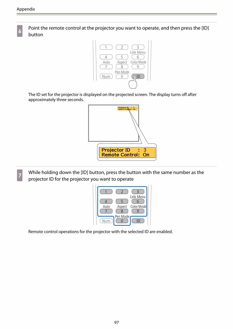
fPoint the remote control at the projector you want to operate, and then press the [ID]button
The ID set for the projector is displayed on the projected screen. The display turns off afterapproximately three seconds.
gWhile holding down the [ID] button, press the button with the same number as theprojector ID for the projector you want to operate
Remote control operations for the projector with the selected ID are enabled.

Appendix
98
hPress the [ID] button and check the ID setting
The following is displayed.
• Remote Control: On is displayed: You can operate the projector currently being operated.• Remote Control: Off is displayed: You cannot operate the projector with the remote control. Repeat the
procedure above to enable remote control operations.
c• Each time the projector is turned on, you need to select the projector ID for the projector you
want to operate. When the projector is turned on, the ID set for the remote control is 0.• When Projector ID is set to Off, you can operate the projector using the remote control
regardless of the ID setting selected using the remote control.• When the remote control ID is set to 0, you can operate all of the projectors regardless of the
projector ID setting.
Adjusting the Image in Multi-Projection
• Check that projector position adjustment is complete
s"Adjusting the Position of the Projector" p.46• If you are concerned about the alignment between images being projected in multi-projection, try performing Arc
Correction.
s"Arc Correction" p.53
aTurn on the projector, and then press the [Menu] button
Using the Remote Control Using the Control Panel

Appendix
99
bSelect Multi-Projection from Extended
cSet Multi-Projection to On
Press the [Esc] button to return to the previous screen.
dMake each setting
Color Mode Set the same item for each projector.Color Uniformity Adjust the color balance for the entire screen (only when necessary).Brightness Level If the brightness for each lamp is different, adjust the lamp brightness
from level 1 to 5. Adjust the darkest lamp as the standard. This is onlyavailable when Power Consumption is set to Normal from the ECOmenu.
Color Matching Adjust the color and brightness in gradations from all white to all black.
When two projectors are installed in parallel and you are using the interactive function
When two projectors are installed in parallel and you want to use the interactive function, after adjusting theimage for multi-projection, make the following settings. Make the settings for each projector in turn. Youcannot set the two projectors at the same time.
a Setting Projector Synchronization (s p.100)
b Setting Multi-Projection Interactive (s p.101)
cWhen two images overlap, the interactive function does not work correctly.
Appendix
100
Setting the projectors in sync
When using the interactive function for multi-projection, interactive pen operations become unstable dueto infrared interference. Follow the steps below to stabilize operations for the interactive pen. Check thatinstallation is complete for both projectors before making settings.
s "Installing the Setting Plate" p.32
aConnect the SYNC ports for each projector by using the optional remote control cable set(ELPKC28)
When the projectors are connected by cable, operations for the interactive pen stabilize.
The SYNC port has an IN and OUT socket. When you connect one end of the remote control cable setto an IN socket, connect the other end to an OUT socket.
In Out
bTurn on the projector, and then press the [Menu] button
Using the Remote Control Using the Control Panel
cSelect Easy Interactive Function from Extended

Appendix
101
dSelect Advanced
eSet Sync of Projectors to Wired
Setting Multi-Projection Interactive
Before setting Multi-Projection Interactive, check that you have finished adjusting the image for multi-projection. If you perform image adjustment after setting interactive, the pen position may not be correct.
s "Adjusting the Image in Multi-Projection" p.98
The procedure differs depending on whether or not the Touch Unit is used.
When not using the Touch Unit
aTurn on the projector on the left and turn off the projector on the right
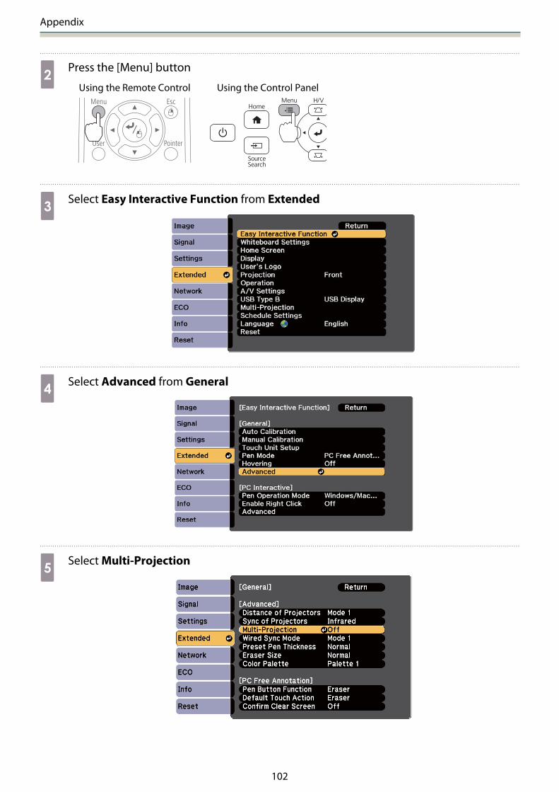
Appendix
102
bPress the [Menu] button
Using the Remote Control Using the Control Panel
cSelect Easy Interactive Function from Extended
dSelect Advanced from General
eSelect Multi-Projection
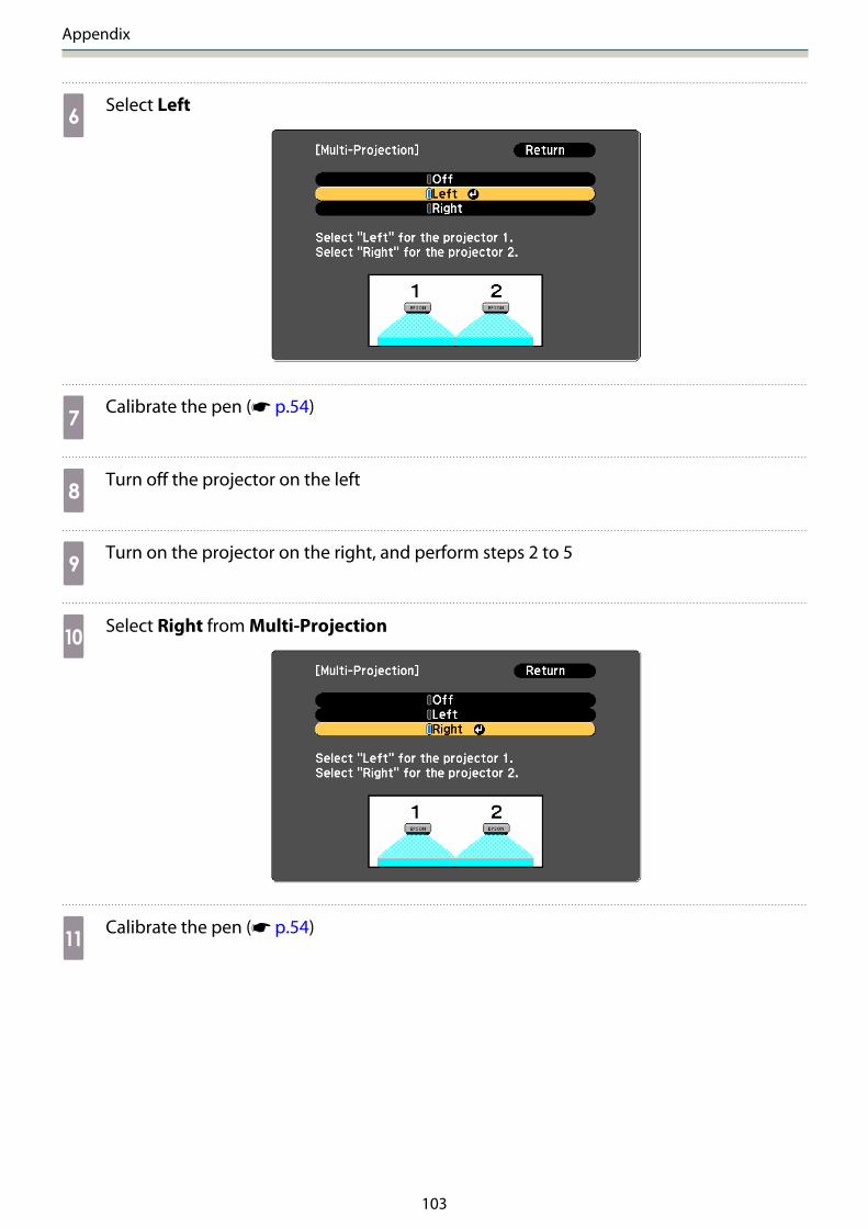
Appendix
103
fSelect Left
gCalibrate the pen (s p.54)
hTurn off the projector on the left
iTurn on the projector on the right, and perform steps 2 to 5
jSelect Right from Multi-Projection
kCalibrate the pen (s p.54)
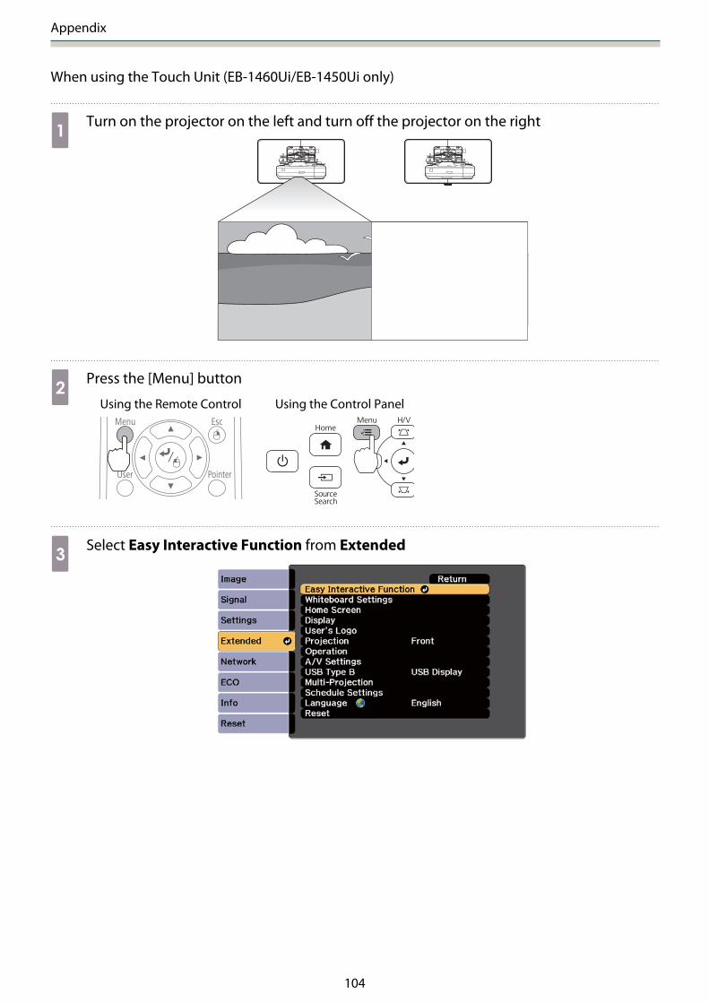
Appendix
104
When using the Touch Unit (EB-1460Ui/EB-1450Ui only)
aTurn on the projector on the left and turn off the projector on the right
bPress the [Menu] button
Using the Remote Control Using the Control Panel
cSelect Easy Interactive Function from Extended

Appendix
105
dSelect Advanced from General
eSelect Multi-Projection
fSelect Left
gCalibrate the pen (s p.54)

Appendix
106
hInstalling and adjusting the angle for the Touch Unit
The procedure differs depending on where the Touch Unit is installed.
When installing the Touch Unit outside the whiteboard (using the Touch Unit Bracket)
a Installing the Touch Unit (s p.64)
b Adjusting the Angle of Laser Diffusion (s p.69)
When installing the Touch Unit on the whiteboard (without using the Touch Unit Bracket)
a Installing the Touch Unit (s p.87)
b Adjusting the Angle of Laser Diffusion (s p.91)
iTurn off the projector on the left
jTurn on the projector on the right, and perform steps 2 to 5
kSelect Right from Multi-Projection
lCalibrate the pen (s p.54)
mInstalling and adjusting the angle for the Touch Unit
The procedure differs depending on where the Touch Unit is installed.
• When installing the Touch Unit outside the whiteboard (using the Touch Unit Bracket)
• Installing the Touch Unit (s p.64)• Adjusting the Angle of Laser Diffusion (s p.69)
• When installing the Touch Unit on the whiteboard (without using the Touch Unit Bracket)
• Installing the Touch Unit (s p.87)• Adjusting the Angle of Laser Diffusion (s p.91)
nTurn on the projectors on the left and right

Appendix
107
oPerforming touch calibration for each projector (s p.84)

Appendix
108
Batch Setup Function
After making the projector's menu settings for one projector, you can copy the settings to other projectors(batch setup function). The batch setup function is only for projectors with the same model number.
Use one of the following methods.
• Setup using a USB flash drive.• Setup using EasyMP Network Updater.
This guide explains the USB flash drive method.
c• The following menu settings are not copied by the batch setup function.
• Network menu settings (except for the Notifications menu and the Others menu)• Lamp Hours and Status from the Info menu
• Perform batch setup before adjusting the position of the projectors. Adjustment values for theprojected image, such as Keystone, are copied by the batch setup function. If batch setup is performedafter adjusting the position of the projectors, the adjustments you made may change.
• By using the batch setup function, the registered User's Logo is copied to the other projectors. Do notregister confidential information and so on as the User's Logo.
Caution
Performing batch setup is the customers responsibility. If batch setup fails due to a power failure,communication error, and so on, the customer is responsible for any repair costs incurred.
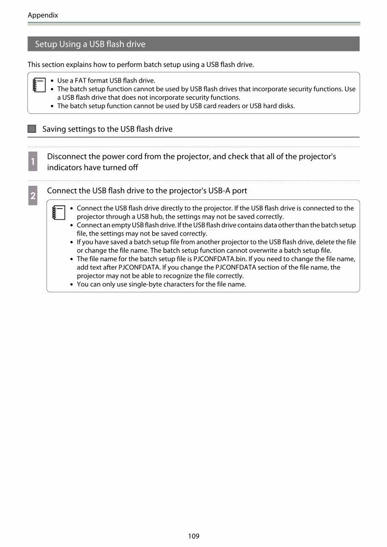
Appendix
109
Setup Using a USB flash drive
This section explains how to perform batch setup using a USB flash drive.
c• Use a FAT format USB flash drive.• The batch setup function cannot be used by USB flash drives that incorporate security functions. Use
a USB flash drive that does not incorporate security functions.• The batch setup function cannot be used by USB card readers or USB hard disks.
Saving settings to the USB flash drive
aDisconnect the power cord from the projector, and check that all of the projector'sindicators have turned off
bConnect the USB flash drive to the projector's USB-A port
c• Connect the USB flash drive directly to the projector. If the USB flash drive is connected to the
projector through a USB hub, the settings may not be saved correctly.• Connect an empty USB flash drive. If the USB flash drive contains data other than the batch setup
file, the settings may not be saved correctly.• If you have saved a batch setup file from another projector to the USB flash drive, delete the file
or change the file name. The batch setup function cannot overwrite a batch setup file.• The file name for the batch setup file is PJCONFDATA.bin. If you need to change the file name,
add text after PJCONFDATA. If you change the PJCONFDATA section of the file name, theprojector may not be able to recognize the file correctly.
• You can only use single-byte characters for the file name.

Appendix
110
cWhile holding down the [Esc] button on the remote control or the control panel, connectthe power cord to the projector
The status indicator and the power indicator turn blue, and the lamp indicator and the temperatureindicator turn orange.
When all of the projector's indicators turn on, release the [Esc] button.
When all of the indicators start flashing, the batch setup file is being written.
Caution
• Do not disconnect the power cord from the projector while the file is being written. If the power cordis disconnected, the projector may not start correctly.
• Do not disconnect the USB flash drive from the projector while the file is being written. If the USB flashdrive is disconnected, the projector may not start correctly.
When writing completes normally, the projector turns off, and only the power indicator is lit blue.
When the power turns off, remove the USB flash drive.
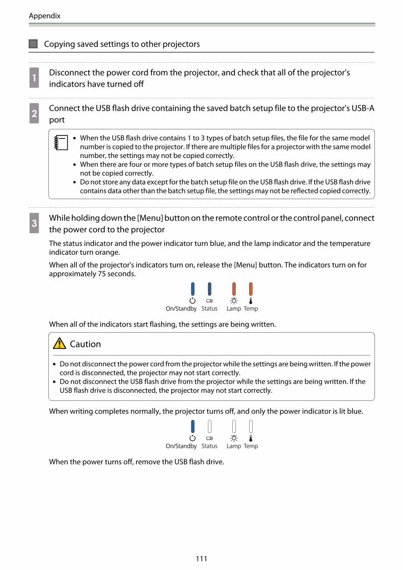
Appendix
111
Copying saved settings to other projectors
aDisconnect the power cord from the projector, and check that all of the projector'sindicators have turned off
bConnect the USB flash drive containing the saved batch setup file to the projector's USB-Aport
c• When the USB flash drive contains 1 to 3 types of batch setup files, the file for the same model
number is copied to the projector. If there are multiple files for a projector with the same modelnumber, the settings may not be copied correctly.
• When there are four or more types of batch setup files on the USB flash drive, the settings maynot be copied correctly.
• Do not store any data except for the batch setup file on the USB flash drive. If the USB flash drivecontains data other than the batch setup file, the settings may not be reflected copied correctly.
cWhile holding down the [Menu] button on the remote control or the control panel, connectthe power cord to the projector
The status indicator and the power indicator turn blue, and the lamp indicator and the temperatureindicator turn orange.
When all of the projector's indicators turn on, release the [Menu] button. The indicators turn on forapproximately 75 seconds.
When all of the indicators start flashing, the settings are being written.
Caution
• Do not disconnect the power cord from the projector while the settings are being written. If the powercord is disconnected, the projector may not start correctly.
• Do not disconnect the USB flash drive from the projector while the settings are being written. If theUSB flash drive is disconnected, the projector may not start correctly.
When writing completes normally, the projector turns off, and only the power indicator is lit blue.
When the power turns off, remove the USB flash drive.

Appendix
112
When Setup Fails
Check Remedy
Are the lamp indicator and the tempera-ture indicator flashing orange quickly?
The batch setup file may be corrupt, or the USB flash drive may notbe connected correctly. Disconnect the USB flash drive, unplug andthen plug in the projector's power cord, and then try again.
Are the power indicator and the status in-dicator flashing blue quickly, and the lampindicator and the temperature indicatorflashing orange quickly?
Writing the settings may have failed and an error may have occurredin the projector's firmware. Stop using the projector, remove thepower plug from the electrical outlet, and contact Epson for help.
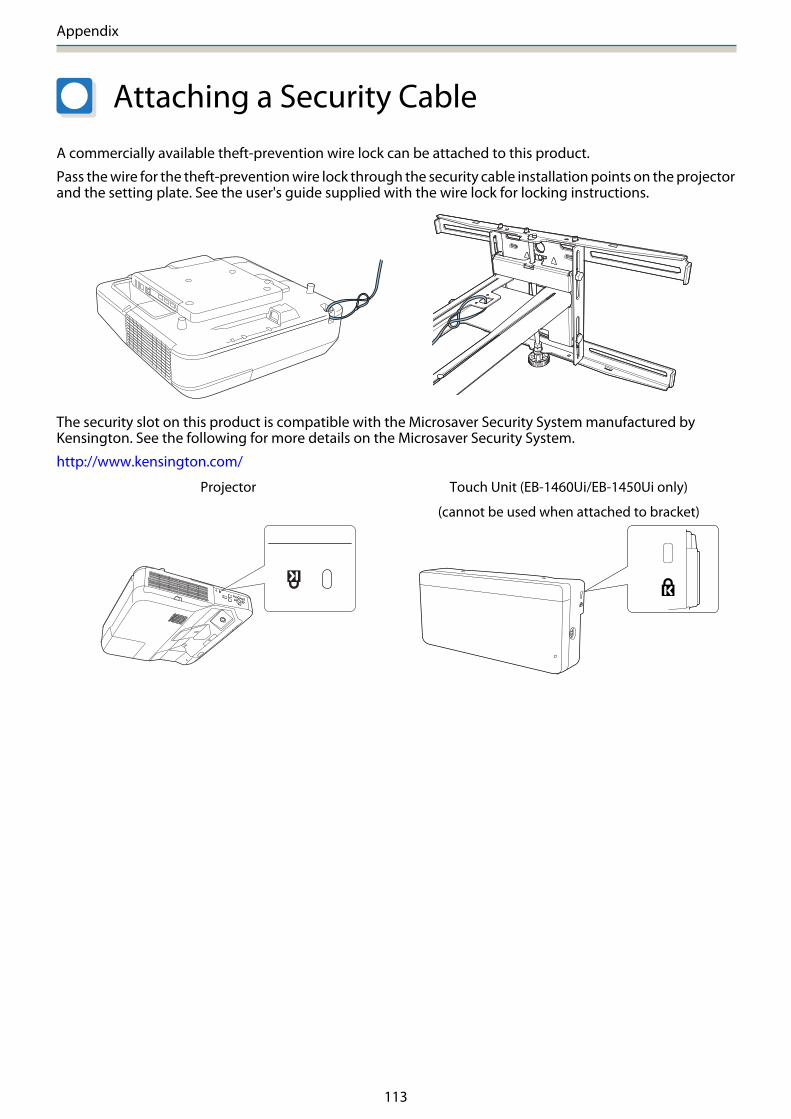
Appendix
113
Attaching a Security Cable
A commercially available theft-prevention wire lock can be attached to this product.
Pass the wire for the theft-prevention wire lock through the security cable installation points on the projectorand the setting plate. See the user's guide supplied with the wire lock for locking instructions.
The security slot on this product is compatible with the Microsaver Security System manufactured byKensington. See the following for more details on the Microsaver Security System.
http://www.kensington.com/
Projector Touch Unit (EB-1460Ui/EB-1450Ui only)
(cannot be used when attached to bracket)

Appendix
114
General Notice
OS X is a trademark of Apple Inc.
Microsoft and Windows are trademarks or registered trademarks of Microsoft Corporation in the United Statesand/or other countries.
©SEIKO EPSON CORPORATION 2016. All rights reserved.