epri independent peer review of the tepco seismic...
TRANSCRIPT

EPRI Independent Peer Review of the TEPCO Seismic Walkdown and Evaluation of the
Kashiwazaki-Kariwa Nuclear Power Plants
A Study in Response to the July 16, 2007, NCO Earthquake
1016317
WARNING: Please read the Export Control Agreement on the back cover.
Effective August 6, 2009, this report has been made publicly available in accordance with Section 734.3(b)(3) and published in accordance with Section 734.7 of the U.S. Export Administration Regulations. As a result of this publication, this report is subject to only copyright protection and does not require any license agreement from EPRI. This notice supersedes the export control restrictions and any proprietary licensed material notices embedded in the document prior to publication

EPRI Project Managers J. Kernaghan R. Kassawara
ELECTRIC POWER RESEARCH INSTITUTE 3420 Hillview Avenue, Palo Alto, California 94304-1338 • PO Box 10412, Palo Alto, California 94303-0813 • USA
800.313.3774 • 650.855.2121 • [email protected] • www.epri.com
EPRI Independent Peer Review of the TEPCO Seismic Walkdown and Evaluation of the Kashiwazaki-Kariwa Nuclear Power Plants A Study in Response to the July 16, 2007, NCO Earthquake
Independent Peer Review, January 2008

DISCLAIMER OF WARRANTIES AND LIMITATION OF LIABILITIES
THIS DOCUMENT WAS PREPARED BY THE ORGANIZATION(S) NAMED BELOW AS AN ACCOUNT OF WORK COSPONSORED BY THE ELECTRIC POWER RESEARCH INSTITUTE, INC. (EPRI) AND THE TOKYO ELECTRIC POWER COMPANY (TEPCO). NEITHER EPRI, ANY MEMBER OF EPRI, TEPCO, THE ORGANIZATION(S) BELOW, NOR ANY PERSON ACTING ON BEHALF OF ANY OF THEM:
(A) MAKES ANY WARRANTY OR REPRESENTATION WHATSOEVER, EXPRESS OR IMPLIED, (I) WITH RESPECT TO THE USE OF ANY INFORMATION, APPARATUS, METHOD, PROCESS, OR SIMILAR ITEM DISCLOSED IN THIS DOCUMENT, INCLUDING MERCHANTABILITY AND FITNESS FOR A PARTICULAR PURPOSE, OR (II) THAT SUCH USE DOES NOT INFRINGE ON OR INTERFERE WITH PRIVATELY OWNED RIGHTS, INCLUDING ANY PARTY'S INTELLECTUAL PROPERTY, OR (III) THAT THIS DOCUMENT IS SUITABLE TO ANY PARTICULAR USER'S CIRCUMSTANCE; OR
(B) ASSUMES RESPONSIBILITY FOR ANY DAMAGES OR OTHER LIABILITY WHATSOEVER (INCLUDING ANY CONSEQUENTIAL DAMAGES, EVEN IF EPRI OR ANY EPRI REPRESENTATIVE HAS BEEN ADVISED OF THE POSSIBILITY OF SUCH DAMAGES) RESULTING FROM YOUR SELECTION OR USE OF THIS DOCUMENT OR ANY INFORMATION, APPARATUS, METHOD, PROCESS, OR SIMILAR ITEM DISCLOSED IN THIS DOCUMENT.
ORGANIZATION(S) THAT PREPARED THIS DOCUMENT
ARES Corporation, Inc.
Electric Power Research Institute (EPRI)
James J. Johnson and Associates
W. Schmidt Consulting
This is an independent peer review prepared by EPRI.
NOTE
Electric Power Research Institute, EPRI, and TOGETHER…SHAPING THE FUTURE OF ELECTRICITY are registered service marks of the Electric Power Research Institute, Inc.
Copyright © 2008 Electric Power Research Institute, Inc. All rights reserved.

iii
CITATIONS
This report was prepared by
ARES Corporation, Inc. 5 Hutton Centre Drive , Suite 610 Santa Ana, CA 92707
Principal Investigator G. Hardy
Electric Power Research Institute (EPRI) 1300 W.T. Harris Blvd. Charlotte, NC 28262
Principal Investigator J. Kernaghan
James J. Johnson and Associates 7 Essex Court Alamo, CA 94507
Principal Investigator J. Johnson
W. Schmidt Consulting 14250 Royal Harbour Court Fort Meyers, FL 33908
Principal Investigator W. Schmidt
This report is an independent peer review conducted for the benefit of the electric power industry and the Tokyo Electric Power Company (TEPCO).
This report should be cited in the following manner:
EPRI Independent Peer Review of the TEPCO Seismic Walkdown and Evaluation of the Kashiwazaki-Kariwa Nuclear Power Plants: A Study in Response to the July 16, 2007, NCO Earthquake. EPRI, Palo Alto, CA: 2008. 1016317.

v
REPORT SUMMARY
Background The Tokyo Electric Power Company’s (TEPCO’s) Kashiwazaki-Kariwa (KK) plant is the largest nuclear power plant in the world with a total output of 8212 MW. The KK plant is 16 kilometers away from the epicenter of the Niigataken-Chuetsu-Oki (NCO) offshore earthquake, which took place at 10:13 a.m. on July 16, 2007, and had a Richter magnitude of 6.6. Ground motion recordings at the basemat of the seven boiling water reactors at the site revealed that the S2 seismic design level had been exceeded during the event.
Restarting a nuclear power plant following an earthquake that exceeds the plant seismic design basis entails a number of tasks to verify that damage has been identified and evaluated and that the plant is in a safe condition to resume operation. TEPCO is currently undertaking these efforts. EPRI determined that performing an independent peer review of the TEPCO seismic walkdown and evaluation program at the KK plants would be of benefit to the seismic engineering community. The EPRI peer review took place the week of September 24, 2007. Key areas that were included in the peer review were: visible damage to critical safety-related structures, systems, and components (SSCs); the degree to which the seismic design basis was exceeded; review of available elements of the TEPCO Comprehensive Assessment Program Plan; and specific peer-review focus areas.
Objective • To provide an independent assessment and review of the current TEPCO seismic walkdown
and review program for the KK nuclear plant
Approach The peer review used a “vertical slice” approach, which consisted of sampling and reviewing the critical elements of the TEPCO program. Experts from the U.S. provided insights and experience from relevant past EPRI studies and also incorporated U.S. experience relative to nuclear plant effects in response to significant earthquakes. The independent peer review was guided by the criteria documented in EPRI report NP-6695, Guidelines for Nuclear Plant Response to an Earthquake, and by ANSI/ANS-2.23-2002, Nuclear Plant Response to an Earthquake. These documents provide guidelines for performing visual inspections and tests of nuclear plant equipment and structures that are required prior to the restart of a nuclear power plant that has been shut down due to an earthquake. They also provide guidance on the scope of nuclear power plant SSC types to address. This methodology was used to review both safety-related (SR) and non-safety-related (NSR) components in KK Units 1 and 7, which are the oldest and newest units and includes the unit with the highest NCO earthquake seismic motion.

vi
Results Based on the sampling visual review performed, KK SR SSCs performed very well in response to the NCO earthquake. No visible damage to the representative SR components reviewed could be detected. This was attributed, among other factors, to the rugged seismic design for the KK plant, particularly for the supports and anchorage.
Instances of damage were identified for some non-safety related (NSR) SSCs. While the results of this NSR damage may not have had critical safety-related ramifications, it was the review team’s observation that certain upgrades could prevent issues that occurred following the earthquake related to communications, fire protection, and available services.
The peer review was based on visual inspections of representative SSCs, but TEPCO has plans in place for operability reviews, detailed testing, and detailed inspections for safety-related items. The review team was able to review selected specific plans and results to date and found these plans to be comprehensive. The overall assessment of the TEPCO NCO earthquake response program is that it is being conducted in a thorough and competent manner, consistent with—and, in some areas, more extensive than—the guidelines of the ANSI/ANS standard. Completion of these plans is essential to the KK NCO earthquake investigation program. Considering the lack of any significant physical or functional damage observed to date to safety-related SSCs, and if ongoing investigations confirm this general finding, consideration could be given to a tiered investigative approach, as suggested in ANSI/ANS Standard 2.23. Such an approach would employ systematic, structured sampling in lieu of 100% coverage.
EPRI Perspective This report represents the consensus position of the EPRI independent seismic expert team who conducted a peer review of the Kashiwazaki-Kariwa nuclear power plant following the July 16, 2007, Niigataken-Chuetsu-Oki earthquake. In addition to the findings of the expert team, this document contains significant information on the actual performance of nuclear power plants during seismic events.
Keywords Earthquake Seismic Nuclear power plant

vii
ACKNOWLEDGMENTS
This report represents the consensus position of the EPRI independent seismic expert team who conducted a peer review of the Kashiwazaki-Kariwa (KK) nuclear power plant following the July 16, 2007, Niigataken-Chuetsu-Oki Earthquake. The EPRI Peer Review Team would like to acknowledge the following TEPCO staff members who provided logistical support, plant access, seismic response data, and plant status/effects information during this peer review:
Name Title
Akio Takahashi Executive Officer, Superintendent
Akio Toba Deputy Site Manager
Susumu Kawamata Unit Superintendent
Naoki Anahara Manager, Maintenance Dept
Susumu Kunito Nuclear Plant Safety
Toshihiro Masuda Manager, Reactor Project Group
Hideki Masui Manager, Engineering Group
Yoshifumi Hashimoto Team Leader, Engineering Group
Yoshinori Watahiki Team Leader, Reactor Project Group
Toshio Ueguri Team Leader, Electrical Equip Group
Kazuya Yamada Unit 3 Operator
Kenji Murano Group Manager, Nuclear Asset Group
Kazuyuki Nagasawa Deputy Manager
Hiroyuki Mizutani Architectural Engineering Group
Ryousuke Inoue Senior Engineer, Quality & Safety
Junichi Sakai Interpreter


ix
CONTENTS
1 OBJECTIVE............................................................................................................................1-1
2 INTRODUCTION AND BACKGROUND ................................................................................2-1 2.1 Peer Review Project Scope and Description ...............................................................2-1 2.2 Expert Panel Description .............................................................................................2-2 2.3 Background on Criteria for Nuclear Plant Response to an Earthquake.......................2-3
3 DEVELOPMENT OF A REPRESENTATIVE PEER REVIEW LIST OF EQUIPMENT AND STRUCTURES..................................................................................................................3-1
4 CONDUCT OF PEER REVIEW ..............................................................................................4-1 4.1 Plant Visual Inspection of Representative Equipment .................................................4-1
4.1.1 KK Unit 1 Walkdown Review...............................................................................4-3 4.1.2 KK Unit 7 Walkdown Review...............................................................................4-3 4.1.3 KK Switchyard, Offsite Power and Yard Components Review ...........................4-4
4.2 Review of KK Plant Overall Strategic Plan ..................................................................4-7 4.2.1 Rough Visual Inspection .....................................................................................4-7
4.2.1.1 Niigataken-Chuetsu-Oki Earthquake (NCOE) Related Non-Conformances: Categorization ...................................................................................4-7 4.2.1.2 Cracks in Reinforced Concrete Structural Elements and Masonry...............4-9 4.2.1.3 Soil Failures ................................................................................................4-10 4.2.1.4 Equipment Anchorage ................................................................................4-12 4.2.1.5 Class C Structure and Component Performance During the NCOE...........4-12
4.2.2 Inspection of Reactor Internals, Recirculation System Piping and Fuel............4-13 4.3 Comparison of TEPCO Plans with ANSI/ANS 2.23-2002 Guidelines........................4-14
4.3.1 Evaluation and Validation of Measured Seismic Recordings............................4-14 4.3.2 Computation of the Cumulative Average Velocity (CAV) ..................................4-15 4.3.3 Determination of the EPRI Damage Intensity ...................................................4-15
x
4.3.4 Performance of Focused and Expanded Visual Inspections of Safety-Related SSCs and Other Damage Indicators.................................................................4-16 4.3.5 Performance of Analytical Evaluations and Supplemental Inspections, Examinations and Tests .................................................................................................4-17
5 CONCLUSIONS AND LESSONS LEARNED ........................................................................5-1
A PEER REVIEW WALKDOWN FORMS ................................................................................ A-1
B PEER REVIEW TEAM MEMBER RESUMES....................................................................... B-1

xi
LIST OF FIGURES
Figure 1-1 Kashiwazaki-Kariwa Nuclear Power Plant................................................................1-1 Figure 4-1 Ceiling Damage in Administration Building...............................................................4-5 Figure 4-2 Damage to Domestic Water Tank Anchorage in KK Plant Yard...............................4-5 Figure 4-3 Vast Majority of Switchyard Exhibited No Damage ..................................................4-6 Figure 4-4 Bushing Plate Junction to Termination Stack ...........................................................4-6 Figure 4-5 Failure of Underground Piping................................................................................4-11 Figure 4-6 Ground Subsidence at Fuel Oil Tank .....................................................................4-11


xiii
LIST OF TABLES
Table 2-1 Structures, Systems and Components Included within the EPRI NP-6695 Methodology.......................................................................................................................2-4
Table 2-2 EPRI Damage Intensity Criteria (EPRI NP-6695) ......................................................2-5 Table 3-1 List of Equipment Reviewed for Peer Review (Categories 1-9).................................3-2 Table 4-1 TEPCO KK Event Categorization ..............................................................................4-8 Table 4-2 TEPCO KK Event Sub-Categories ............................................................................4-9 Table 4-3 ANSI/ANS 2.23 Seismic Damage Intensity Scale ...................................................4-20
Table A-1 List of KK Equipment Reviewed .............................................................................. A-1


1-1
1 OBJECTIVE
The objective for this expert peer review was to provide an independent assessment and review of the current TEPCO seismic walkdown and review program for the KK nuclear plant. The peer review utilized experts from the U.S. The Team provided insights and experience from relevant past EPRI studies, and incorporated the U.S. experience relative to significant earthquakes effects to nuclear power plants.
Figure 1-1 Kashiwazaki-Kariwa Nuclear Power Plant


2-1
2 INTRODUCTION AND BACKGROUND
Based on the net electrical power rating, the Kashiwazaki-Kariwa (KK) plant is the largest nuclear plant in the world, with a total output of 8,212 MW. This electrical output is sufficient to provide electricity to about 16 million households. Since there are some 47 million households reported by the Japanese census, this makes the Kashiwazaki-Kariwa Nuclear Power Plant an extremely important cornerstone in the electricity market of Japan.
The KK plant is 16 kilometers away from the offshore epicenter of the 2007 Magnitude 6.8 Niigataken-Chuetsu-Oki Earthquake (NCOE) offshore earthquake, which took place 10:13 a.m., July 16, 2007. Ground motion recordings at the basemat of the seven (7) plants at the site revealed that the S2 seismic design level had been exceeded during the event. TEPCO, in consultation with Japanese Nuclear Regulatory Agencies decided to keep the plants shut down until they could confirm the safety of all seven KK units.
The process of restarting a nuclear power plant following an earthquake that exceeds the plant seismic design basis earthquake entails a number of tasks to verify that any damage has been identified and evaluated and that the plant is in a safe condition to continue operation. TEPCO is currently undertaking efforts to review all the anomalies and damage that resulted from this earthquake in all seven (7) units of the KK plant. EPRI concluded that the performance of an independent peer review of the TEPCO seismic walkdown and evaluation program being conducted in response to the July 16, 2007 earthquake effects at the KK plants would be of benefit both to the nuclear power industry and to the seismic engineering community. As such, EPRI offered in August 2007 (K. Huffman to I. Takekuro; August 30, 2007) to perform the review that was then performed the week of September 24, 2007.
2.1 Peer Review Project Scope and Description
The scope of the KK Plant seismic peer review consisted of the following tasks:
1. Review with TEPCO cognizant engineers the performance of the critical KK plant systems and equipment, during and following the July 16, 2007 earthquake.
2. Generate a listing of needed materials and support from TEPCO to provide the peer review team in advance of the KK plant visit in order to optimize the efficiency of the peer review.
3. Perform peer review of the key elements of the TEPCO program plan to assess the damage, assure continued safe shutdown, and potential restart of the KK nuclear plant units.
4. Perform peer review walkdowns of selected portions of the KK plant.
5. Document the results of the expert peer review and walkdown in an EPRI report.
Introduction and Background
2-2
The peer review utilized a “vertical slice” type review of the TEPCO KK Plant seismic review program which consists of a sampling review of the critical elements of the TEPCO program. Key areas that were targeted for the peer review included:
• Seismic Design Basis Exceedance for locations where the response has been measured
• Visible damage to critical safety-related structures, systems and components based on a peer review walkdown as well as a review of the TEPCO documentation of their walkdowns, inspections and non-destructive examinations
• Review of any available elements of the TEPCO Comprehensive Assessment Program Plan:
• Specific Peer Review Focus Areas:
� Damage and anomalies to safety-related equipment and structures
� Damage and anomalies to non-safety-related equipment and structures
� Results of TEPCO post-earthquake evaluations, inspections and tests
� Recommended additional inspections, non-destructive examinations and tests, if considered necessary
� Recommended additional analyses, if considered necessary
� Recommended supplemental in-service inspections and surveillance tests, if considered necessary
2.2 Expert Panel Description
The peer review team consisted of a four-person multi-disciplinary team with the following collective expertise:
• Seismic design, analysis and failure assessment,
• Seismic response of structures, systems and components in nuclear plants,
• Nuclear power plant operations and systems logic, including procedures adopted in the U.S. for nuclear plant response to an earthquake,
• Structural integrity of components subjected to seismic loadings, and
• Post-earthquake investigations.
The experts included of the EPRI peer review team, including their expertise, were:
• Mr. Greg Hardy - Seismic Margins, Earthquake Experience, Peer Review Team Leader
• Mr. Jerry Kernaghan - Nuclear Systems and Components, Project Manager
• Mr. William Schmidt – Seismic Experience, Nuclear Plant Engineering
• Dr. James Johnson - Seismic Design, Analysis and Response
The individual background and qualifications of each of these experts are documented within the resumes contained within Appendix B.

Introduction and Background
2-3
2.3 Background on Criteria for Nuclear Plant Response to an Earthquake
The independent peer review study was guided by the criteria documented within EPRI Report NP-6695 entitled “Guidelines for Nuclear Plant Response to an Earthquake”, and by ANSI/ANS-2.23-2002 “Nuclear Plant Response to an Earthquake”. The EPRI report has been accepted by the U.S. Nuclear Regulatory Commission (USNRC) as a basis for plant response to an earthquake, for evaluation of the impact of the earthquake on important systems, structures and equipment, and for determination of the plant’s readiness to resume operation. (See USNRC Reg. Guides 1.166 and 1.167).
These two documents provide guidelines for performing visual inspections and tests of nuclear plant equipment and structures required for operation prior to restart of a nuclear power plant which has been shut down due to an earthquake. The objective of these guidelines is to assist nuclear plant personnel in the preparation of plant procedures (or the enhancement of existing procedures) for post-shutdown inspections and tests of a nuclear power plant following shutdown due to an earthquake that exceeds the OBE or discovery of significant damage. The purpose of the post-shutdown inspections and tests is to determine the effects of the earthquake on nuclear plant equipment and structures required for operation so that the readiness of the plant to resume operation can be determined in a systematic and timely manner. Two forms of damage must be assessed following a significant earthquake:
1. Functional Damage – Significant damage to plant systems, components, and structures which impairs the operability or reliability of the damaged item to perform its intended function. Minor damage such as slight or hairline cracking of concrete elements in structures does not constitute functional damage.
2. Physical Damage – Damage to plant systems, components and structures which can be detected by visual inspections (e.g. broken parts, cracks, plastic deformation, misalignment of joining components, excessive wear, excessive noise/vibration/temperature for rotating equipment, etc.). The damaged item may or may not be capable of performing its intended function.
The elements of the EPRI peer review visual inspections included:
• Visual inspections of representative equipment anchorage,
• Visual observation of representative piping, conduit and ducting (including supports and attachments),
• Visual observation of representative structures (concrete and steel), and
• Documentation of evidence of structural and potential functional damage.
The peer review also included discussions with key TEPCO engineering and operations staff. As part of these on-site discussions, the peer review team reviewed 1) TEPCO’s strategic plan for post-earthquake evaluations, 2) results of completed visual inspections, 3) observations and sequence of events during and immediately following the earthquake, and 4) plans for specific non-destructive examinations of reactor internals, piping and fuel.

Introduction and Background
2-4
Documentation Forms are contained within EPRI NP-6695 identify key categories of critical equipment within nuclear power plant SSCs which should be included in the scope of a review of the readiness for plant re-start following a significant earthquake. This list of structure, system and component types is included in Table 2-1 below
Table 2-1 Structures, Systems and Components Included within the EPRI NP-6695 Methodology
Equipment/Structure List (EPRI NP-6695)
1. Fans
2. Air Compressors
3. Battery Racks
4. Static Inverters and Battery Chargers
5. Air Handlers
6. Chillers
7. Transformers
8. Vertical Pumps
9. Horizontal Pumps
10. Motor Generators
11. Motor Control Centers
12. Low Voltage Switchgear
13. Medium Voltage Switchgear
14. Distribution Panels
15. Fluid/Air/Motor-Operated Valves
16. Engine-Generators
17. Instrument Racks
18. Sensors
19. Control and Instrumentation Cabinets
20. Low Pressure Storage Tanks
21. High Pressure Tanks and Heat Exchangers
22. Piping
23. Electric Raceways
24. Air Handling Ducts
25. Steel Framed Structures
26. Reinforced Concrete Structures and Masonry Walls
27. Primary Coolant System
28. Buried Pipe
29. Generic Equipment

Introduction and Background
2-5
Another part of the ANSI/ANS 2.23 methodology utilizes a damage intensity measure to define qualitatively the damage potential of an earthquake experienced by a nuclear facility. This damage intensity scale is fully described in EPRI NP-6695 as a function of the effects of the earthquake on nuclear plant SSCs, as well as a number of damage indicators based on experience in past earthquakes. This damage intensity scale is described in detail in NP-6695 and ANSI 2.23 and is summarized in Table 2-2 below. The key feature of this damage scale is that it is based on typical power plant equipment and observations of damage made on the plant site, rather than at a distant locality.
Table 2-2 EPRI Damage Intensity Criteria (EPRI NP-6695)
EPRI Damage Intensity
General Description
0 No damage or distress to safety-related seismic-designed equipment or structures. Some evidence or distress/upset in non-seismic damage indicators.
1 No damage or distress to safety-related, seismic designed equipment or structures. Widespread distress in non-seismic commercial buildings, windows, unreinforced masonry.
2 First evidence of damage/leakage/cracking in safety-related, seismic-designed equipment and structures. Considerable damage to non-seismic civil structures.
3 Clear evidence of permanent deformation, cracking of safety-related equipment, piping supports and structures. Severe damage to civil structures
Walkdown and review guidance was also taken from the following references
• EPRI Post-Earthquake Investigation: Planning and Field Guide.
• Applied Technology Council ATC-20-1, “Field Manual: Post-earthquake Safety Evaluation of Buildings”.
• ATC 20, “Procedures for Post-earthquake Safety Evaluation of Buildings”.
• Earthquake Engineering Research Institute, “Post-Earthquake Investigation Field Guide: Learning from Earthquakes”.
• Seismic Qualification Utility Group, “Generic Implementation Procedure for Seismic Verification of Nuclear Plant Equipment”. Revision 2A, March 1993.


3-1
3 DEVELOPMENT OF A REPRESENTATIVE PEER REVIEW LIST OF EQUIPMENT AND STRUCTURES
As stated earlier, this EPRI independent peer review incorporated a “vertical slice” format of peer review wherein a sampling was conducted for each of the different categories of equipment defined within ANSI/ANS 2.23. There are 29 categories of equipment and systems that have unique seismic review criteria (per ANSI/ANS 2.23 methodology) following large earthquakes. The criteria for selecting the sample of equipment and systems within the peer review walkdown effort consisted of the following elements:
• Selection of two representative components for each of these 29 categories specified within ANSI/ANS 2.23
� Focus on Safety Related (SR) Components
� Inclusion of some Non-Safety-Related (NSR) Components (in order to study the differences in damage and failures observed in SR and NSR components and to provide data for estimation of the EPRI damage intensity which should be assigned to the NCO earthquake at the KK plants)
• Select equipment, structures and components within two different KK units:
� Unit I selected
o Unit 1 experienced the highest seismic motion of all 7 units
o Unit 1 is the oldest of the units (1985 Startup)
o Unit 1 was not operating at the time of the earthquake
o Unit 1 is a BWR-5
o Unit 1 was designed by Toshiba
� Unit 7 selected
o Unit 7 experienced seismic response much closer to the S2 earthquake level
o Unit 7 is the newest of the KK Plant units (1997 Startup)
o Unit 7 was operating at the time of the earthquake
o Unit 7 is an ABWR Design
o Unit 7 was designed by a combination of Toshiba, Hitachi and GE
• Include switchyard and other on-site equipment and infrastructure

Development of a Representative Peer Review List of Equipment and Structures
3-2
The resulting list of SSCs was judged to encompass a broad range of locations, response levels, potential failure modes and equipment type and serves as a representative population for the vertical slice review. Table 3-1 contains the list of equipment reviewed for this project.
Table 3-1 List of Equipment Reviewed for Peer Review (Categories 1-9)
Form
Equipment/ Structure Data
Forms NP-6695
Component Seismic Class
KK Unit 1
KK Unit 7
Date Reviewed
Diesel Generator Start As X 9/26/2007 1
Air Compressors Diesel Generator Start As X 9/27/2007
HPCF Air Handlers A X 9/26/2007 2 Air Handlers
Main Control Room A X 9/27/2007
HPCF Room A X 9/26/2007 3
Air Handling Ducts Main Control Room A X 9/27/2007
Emergency DC Power A X 9/26/2007 4 Battery Racks
Emergency DC Power A X 9/27/2007
Fire Protection Piping at Diesel Oil Storage Tank C X 9/27/2007
5 Buried Pipe Drinking Water Underground Piping C X 09/25/07
C/A Chiller C X 9/27/2007
6 Chillers HVAC Emergency Cooling Water (HECW) As X 9/26/2007
Control Room - Generator and Transformer Protection Relay Cabinet A X 9/27/2007 7
Control and Instrumentation Cabinets Auto Voltage Regulator (AVR)
Panel A X 9/27/2007
ESS II (Emergency MCC Room B) As X 9/27/2007
8 Distribution Panels Emergency Room Distribution
Panel As X 9/27/2007
Cable Spreading Room A X 9/27/2007 9
Electric Raceways Cable Spreading Room A X 9/26/2007

Development of a Representative Peer Review List of Equipment and Structures
3-3
Table 3-1 (continued) List of Equipment Reviewed for Peer Review (Categories 10-19)
Form
Equipment/ Structure
Data Forms NP-6695
Component Seismic Class
KK Unit 1
KK Unit 7
Date Reviewed
Diesel Generator As X 9/27/2007 10
Engine-Generators Diesel Generator As X 9/26/2007
Drywell Ventilation Fans C X 9/27/2007
11 Fans Ceiling Mounted Fan (Diesel Room) As X 9/26/2007
Air Operated Valves in HCU/SCRAM System As X 9/26/2007 12
Fluid/Air/Motor- Operated Valves 4 Feedwater MOVs B X 9/26/2007
Seismic Accelerometers C X 09/25/07 13
General Equipment Switchyard C X X 09/28/07
RHR Heat Exchanger As X 09/27/07
14
High Pressure Tanks and Heat Exchangers
High Pressure Feedwater Heat Exchanger B X 9/26/2007
Turbine Driven Reactor Feedwater B X 9/26/2007 15 Horizontal
Pumps "B" HPCF Core Flooding Pump As X 09/26/07
General Instrument Rack C X 9/27/2007
16 Instrument Racks Feedwater Pump Instrument
Rack B X 9/25/2007
Diesel Oil Tank A X 9/27/2007
Demineralized Water and Caustic Storage Tanks C X 9/25/2007
17 Low Pressure Storage Tanks
Outdoor Filtrated Water Tank C X 9/26/2007
Emergency Diesel Generator Switchgear As X 9/27/2007
18 Low Voltage Switchgear Emergency Diesel Generator
Switchgear As X 9/26/2007
Metal Clad Switchgear 6.9 KV As X 9/27/2007 19
Medium Voltage Switchgear Metal Clad Switchgear 6.9 KV As X 9/26/2007

Development of a Representative Peer Review List of Equipment and Structures
3-4
Table 3-1 (continued) List of Equipment Reviewed for Peer Review (Categories 20-29)
Form
Equipment/ Structure
Data Forms NP-6695
Component Seismic Class
KK Unit 1
KK Unit 7
Date Reviewed
480V MCC 1C-1-5 A X 9/27/2007
20 Motor Control Centers Turbine Bldg Radiation Monitor
MCC C X 9/26/2007
PLR MG set #1 C X 9/27/2007 21
Motor Generators PLR MG set #2 C X 9/27/2007
SLC Piping As X 9/27/2007
22 Piping Reactor Bldg piping supported off wall As X 9/27/2007
HCU As X 9/27/2007 23
Primary Coolant System HCU As X 9/26/2007
Reinforced Concrete Wall - TB Op Flr - B X 9/26/2007
24
Reinforced Concrete Structures and Masonry Walls
Turbine Pedestal - TB Op Flr - Pounding B X 9/26/2007
Temperature Sensor - RB HCU Room Balcony As X 9/26/2007 25 Sensors
RTD B X 9/26/2007
Battery Charger A X 9/27/2007
26
Static Inverters and Battery Chargers Battery Charger A X 9/26/2007
Outer Pump Structure(CWP Building) C X 9/27/2007 27 Steel Framed
Structures Turbine Bldg Operating Floor C X 9/26/2007
Power Center A X 9/27/2007
28 Transformers Transformers high on wall in hallway C X 9/27/2007
Sea Water Pumps C X 9/27/2007 29
Vertical Pumps RHSW Pumps As X 9/27/2007
4-1
4 CONDUCT OF PEER REVIEW
The EPRI Peer Review Team was assisted during the KK Plant review by a team of TEPCO engineers that provided technical and logistical support. The TEPCO support team was very cooperative, conscientious and knowledgeable and their support was instrumental to the implementation of this review. The peer review consisted of three key elements which are discussed in the sections below.
1. Plant Visual Inspection of Representative Equipment (Section 4.1)
2. Review of KK Plant Overall Strategic Plan (Section 4.2)
3. Application of ANSI/ANS Standard 2.23-2002 Guidelines to the KK Plant (Section 4.3)
In the course of review of these three key elements, the Peer Review Team:
• Reviewed completed TEPCO visual inspection forms
• Reviewed completed TEPCO inspections, tests and findings
• Interviewed cognizant TEPCO engineers (including two control room operators who were on duty at the time of the earthquake) relative to the plant performance during/following the earthquake
4.1 Plant Visual Inspection of Representative Equipment
As stated in Section 3, the peer review walkdowns concentrated on representative equipment within Units 1 and 7, together with a review of the switchyard and some site yard equipment. The specific walkdown data sheets for each of the components reviewed are contained in Appendix A.
The specific observations of this review are captured in the sections 4.1.1 through 4.1.3 while overall general observations are noted below:
• Unit 1 Observations – Section 4.1.1
• Unit 7 Observations – Section 4.1.2
• Offsite Power, Switchyard and Yard Equipment/Structures Observations – Section 4.1.3

Conduct of Peer Review
4-2
General Observations
The appearance of the safety-related (SR) structures and equipment reviewed (Units 1 and 7) presented a significant contrast to the general appearance of the non-safety-related (NSR) structures and equipment in the yard areas around the plants. The SR buildings, foundations and equipment appear almost completely unaffected by the earthquake, are generally in excellent condition, with virtually no signs of any significant damage. On the other hand, the outside yard NSR service buildings, such as the water treatment building, Unit 1 pump house and water storage tanks exhibited significant damage. General observations also include:
• It was noted that Unit 7’s circulating and safety-related RSW system designs differ from Units 1 through 4 in that they are a part of the turbine building. As a result, these components and systems showed no evidence of damage. This is in contrast to the NSR pump house building and systems for Unit 1 which had considerable damage.
• Walkdown inspections of a representative sample of safety-related SSCs in Units 1 and 7 conducted over three days by the EPRI Peer Review Team revealed essentially no significant damage, and no minor damage which is believed to have safety significance. In particular, safety-related equipment and systems representative of essentially all equipment and system types were found to be adequately anchored, piping and other distribution systems and their supports appeared undisturbed and robust. These observations are consistent with summaries of inspections provided by TEPCO.
• Interviews with TEPCO engineers and operators, including several who were on duty at the time of the earthquake, indicated that while numerous alarms were actuated in the control room during the 20 or so seconds of strong motion, none have been determined to be significant at the time of the peer review. A number of components operating before the earthquake (and not designed to trip along with the automatic trips in response to the earthquake) continued to function without interruption during and after the earthquake. Examples include the RHR and RSW pumps for Unit 1. The Unit 1 and Unit 7 emergency diesels have also been confirmed to be operable following the earthquake. TEPCO reported that operability tests of all of the equipment will be conducted as part of their planned investigations.
• While there were a number of anomalous events such as the Unit 3 house transformer settlement and fire, sloshing of spent fuel pool water, a small portion of which eventually found its way to the sea, none represented a significant challenge to plant safety or the environment based on the preliminary observations.
In summary, while the NCO earthquake was a significant, strong motion earthquake that appears to have exceeded each unit’s design basis earthquake (S2) by a significant amount, the physical condition of safety-related nuclear plant SSCs reviewed during the peer review demonstrate that the seismic design of the safety-related SSCs of both Units 1 and 7 (and by inference the other five units which experienced lower seismic loads and were newer in vintage than Unit 1) have substantial seismic margin beyond the original design basis. This observation is in contrast to the non-safety-related, non-nuclear SSCs, particularly those founded on the soft soils with minimal or no seismic design, which suffered significant damage.

Conduct of Peer Review
4-3
4.1.1 KK Unit 1 Walkdown Review
Observations from the Unit 1 review include:
• The NSR CW pump house building, foundation and equipment suffered considerable damage. This pump house structure has three separate foundations which contributed to its poor performance; one portion on piles, a second portion on the concrete intake piping, and the third on native soil. One service crane toppled over, the other was inoperable (apparently a result of steel structure deformation) and crane rails showed bending/waviness horizontally by as much as 6 to 8 inches. One main circulating water pump was disassembled for overhaul at the time of the earthquake (the unrestrained motor overturned on the floor); the intact circulating water pump was not in operation and suffered no apparent visible damage. Its operability is not yet known. Complete replacement of the pump house building and structures was reported by TEPCO as being considered.
• Adjacent to the Pump House is a separate SR foundation which supports the Emergency Diesel Generator (EDG) fuel oil tank and four sea water pumps, two of which are SR RHR pumps. This foundation showed no visible settlement or movement, although cable trays in an adjacent, NSR cable trench apparently failed and were being temporarily supported as of the time of this visit.
• Observation of conditions in the control room showed no abnormalities. TEPCO reported that one NSR recorder cabinet failed its anchorage in a false floor (architectural, not structural floor) and fell over. No ceiling damage was reported. As in the Unit 6-7 control room, no damage occurred to SR control and instrument panels or components.
4.1.2 KK Unit 7 Walkdown Review
Observations from the Unit 7 review include:
• The main turbines showed a high vibration alarm, but tripped as a result of the automatic scram signal. Turbine shafts apparently showed some shifting and bearing damage was reported by TEPCO as a possibility. The turbines on Units 6 and 7 were to be opened and inspected in October. Fastener heads apparently broke (popped off) on a few panels of floor grating adjacent to the main turbine. The gratings and supports appeared undamaged and undisturbed.
• Minor, local spalling of concrete on the surface of the turbine pedestal was observed at contact points near columns of the turbine building (TB). TEPCO is investigating.
• No other damage was observed to any piping or commodities in the turbine hall, although TEPCO reported that a window on the crane operator’s cab was broken.
• In the unit 6 and 7 control room, several overhead lighting fixtures fell, an unanchored copy machine toppled over, one or more HVAC diffusers fell to the floor, and documents on shelves typically fell out. No significant damage was apparent and reportedly no operators were injured.
• Following the earthquake, operators responded to alarms, verified safe, stable conditions and implemented a formal earthquake response procedure. Operator walkdowns by two

Conduct of Peer Review
4-4
operators were carried out in accordance with walkdown procedure reported to be entitled “Plant Walkdown Following an Earthquake”.
• Offsite power switching occurred automatically, and 2 of 4 lines continued to supply off-site power throughout the event.
• The refueling floor, refueling machine, spent fuel storage racks showed no evidence of an earthquake. There was one temporary work platform normally hung from the side of the SF Pool that was dislodged and fell into the pool. No damage was reported.
4.1.3 KK Switchyard, Offsite Power and Yard Components Review
Observations from the switchyard and yard equipment/structures review included:
• The main components of the NSR switchyard are founded on a single foundation. This foundation and the anchorages of main components were said to be designed for a static acceleration of 0.2g and appeared to be capable of withstanding significantly larger loads. Based on the peer review walkdown, the foundation showed no apparent settlement or distress and the component anchorages were intact. As previously reported, two of the four power feeds continued to supply power throughout the earthquake. The two which were not available were disconnected by protective relaying due to off-site Transmission and Distribution problems (power line slapping, insulator failures and relay malfunctions). The only anomalies reported in the actual switchyard components were a control cabinet (mounted next to but not on the engineered foundation) tipped slightly but that continued to function, and damage to a termination plate at the top of a bushing stack which broke an oil seal.
• The failure/falling of suspended ceiling panels and light fixtures and the breakage of a glass wall partition were reported by TEPCO in NSR structures such as the Administration Building. Un-anchored equipment such as computers fell from desks and documents/books generally fell from their shelves. The access door to the Technical Support Center in the Administrative Building was stuck shut for about 45 minutes following the earthquake, preventing access of personnel to the instrumentation and communication equipment in the Center.
• The general yard area and roadways showed relatively extensive ground ruptures and subsidence due to liquefaction as is further described in section 4.2.1.3.

Conduct of Peer Review
4-5
Figure 4-1 Ceiling Damage in Administration Building
Figure 4-2 Damage to Domestic Water Tank Anchorage in KK Plant Yard

Conduct of Peer Review
4-6
Figure 4-3 Vast Majority of Switchyard Exhibited No Damage
Figure 4-4 Bushing Plate Junction to Termination Stack
In summary, it is considered significant that off-site power was maintained during and after the earthquake in two of four lines, despite the fact that this switchyard is not safety related. This positive performance is not consistent with the experience at other non-nuclear facilities which experienced strong earthquakes. This may be attributed to the fact that the main switchyard foundation and equipment anchorages were reportedly designed for 0.2 g static acceleration. This observation supports a conclusion that this system demonstrates substantial margin compared to its reported seismic design basis.

Conduct of Peer Review
4-7
4.2 Review of KK Plant Overall Strategic Plan
TEPCO presented their process for assessing the impact of the NCO earthquake on their KK Units during the course of the plant visit for the independent peer review. The TEPCO earthquake assessment strategic plan included rough visual inspections of the plant structures, systems and components along with a more detailed inspection program for the more critical elements of the plant radioactive containment elements. The peer review of each of these is described in the sections 4.2.1 and 4.2.2 below. Overall, the review of the TEPCO strategic plan for evaluating the plants’ readiness for re-start concluded that the planned approach is very extensive. The peer review team recommends that TEPCO consider a tiered approach to determine the extent of evaluations required based on the results of specific evaluations performed.
4.2.1 Rough Visual Inspection
TEPCO’s overall approach is to perform Rough Visual Inspections followed by Detailed Inspections. Rough Visual Inspections are characterized by visual inspections without dismantlement of the structures, systems, and components (SSCs) being inspected. Prioritization of SSCs to be inspected was determined based on:
(i) Facilities necessary to keep cold shutdown state; and
(ii) Other Class A facilities
Some associated general observations and recommendations by the EPRI Peer Review Team are contained in the following subsections.
4.2.1.1 Niigataken-Chuetsu-Oki Earthquake (NCOE) Related Non-Conformances: Categorization
The TEPCO post-earthquake inspections of Structures, Systems, and Components (SSCs) on the Kashiwazaki-Kariwa nuclear power plant site (7 units) identified anomalies or non-conformances from normal conditions and categorized them according to their safety significance. Table 4-1 itemizes the descriptions of TEPCO’s categorization ranging from most significant (Grade As) to insignificant (Grade D or X). The table contains the number of events placed in each of the categories – the total being 2799 events as of 12 September 2007. Note, as of 17 October 2007, there are a total of 2898 events (Ref., TEPCO Press Release “Non-Conformances Found in the Inspection and Restoration Works Performed after the Niigata-Chuetsu-Oki Earthquake,” October 18, 2007). The categorization of the additional events (99) was not available for this peer review effort.

Conduct of Peer Review
4-8
Table 4-1 TEPCO KK Event Categorization
Grade Definition Count
As Reportable event based on law or agreement with local government. Significant events, which can affect safety or performance of the plant.
10
A Significant non-conformity against requirement of quality assurance program. Events which can impact schedule of outage.
34
B Non-conformity identified at government inspection. Event requiring intensified operation monitoring.
33
C Insignificant non-conformity against requirement of quality assurance program. (Leakage in controlled area, Minor cracks of structures, etc.)
869
D Event recoverable by ordinary maintenance activity (Non-radioactive leakage, Damage of light or door, etc.)
1847
X Replacement of consumables. 6
Total 2799
In general, the Grade As, A, and B categories of events were translated into English and provided in tabular form. The total of 77 events within these three grades covers all 7 units. The EPRI Peer Review effort concentrated on Units 1 and 7, the yard, and the switchyard as discussed in Sec. 4.1. The EPRI Peer Review Team used the table of events of Grade As, A, and B for these locations as one factor in the decision as to the scope of their independent inspections.
Table 4-2 further breaks down the categories into sub-categories for additional insight into the types of events that are identified in each category. Although this additional information is helpful, it is recommended that in order to gain maximum insights from this data, a further break down of the data should be performed, especially for the Grades C and D. As described during the meetings, an SSC that is classified as Safety Class C, based on its lack of importance to safety, may have experienced significant damage. However, the event will be placed in the Grade C or D category, since it is not an SSC important to safety. Examples are:
• In a given sub-category such as “Crack, ablation (structure)” two events: one associated with observed very minor cracks in a Safety Class As, A, or B structure; the second associated with significant damage to a Safety Class C building will both be categorized as Grade C or D. This leads to a misunderstanding of the actual performance of Safety Class As, A, and B structures compared to Safety Class C structures. Safety Class C structures often experienced partial failure where Class As, A, and B structures in close proximity did not.
• A second example is the case of observed very minor leakage of water from a Safety Class As, A, or B structure or component and the failure of a Safety Class C vertical tank. Both of these events may be sub-categorized as “Leakage of water” and Grade C or D, but the two events are important to understanding the consequences of the NCOE on the Kashiwazaki-Kariwa nuclear power plant.

Conduct of Peer Review
4-9
To have additional information on the failures or lack thereof allows one to further emphasize the safety significance of the seismic analysis and design procedures for nuclear power plant structures, systems, and components when compared with criteria for conventional industrial facilities. It also highlights the fact that damage did occur on site, but structures, systems, and components important to safety were very well designed for earthquake loading conditions and, generally, did not experience failure. Possible improvements to the categorization approach are to present two tables – one for Safety Class As, A, and B items and a second table for Class C items. In addition, further clarification could be provided in the description of the types of failures present in each of the sub-categories, perhaps by example.
Table 4-2 TEPCO KK Event Sub-Categories
Issues As A B C D X Sub-Total
%
Shutdown, water level fluctuation, annunciator
0 3 4 50 89 1 147 5.3%
Contamination, release 1 2 0 1 0 0 4 0.1%
Leakage of water 7 3 5 194 272 0 481 17.2%
Leakage of oil (including chemicals)
0 4 0 39 135 0 178 6.4%
Fire 1 0 0 0 0 0 1 0.0%
Mechanical damage 1 18 6 188 670 0 883 31.5%
Crack, ablation (structure) 0 1 10 355 436 2 804 28.7%
Transmission error, malfunction
0 0 1 9 62 0 72 2.6%
Loss of power, short circuit 0 1 2 7 20 0 30 1.1%
Others 0 2 5 26 163 3 199 7.1%
Totals 10 34 33 869 1847 6 2799 100%
4.2.1.2 Cracks in Reinforced Concrete Structural Elements and Masonry
The EPRI Team observed cracks in some reinforced concrete elements (floor slabs, walls, equipment pedestals) and masonry infill walls. Generally, significant cracking or partial failure was observed only for Safety Class C items. Generally, only minor cracking was observed for Safety Class As, A, or B concrete elements. The EPRI Team met with the TEPCO Structure Group responsible for the structure crack inspection and monitoring program. This group has overall responsibility for crack inspection and monitoring for all units. An initial review for cracks was conducted by the plant operators immediately following the earthquake in

Conduct of Peer Review
4-10
conformance with the TEPCO post earthquake procedure. A more detailed crack investigation was in the process of being conducted while we were conducting this peer review. Elements of the crack inspection and monitoring program are:
• General
� Inspections are performed once per year – last inspection before NCOE was in 2006
� Inventory cracks (location, length, number, ranking)
� Actions (C = crack width)
o C < 0.4 mm - no specific actions required
o 0.4 < C < 0.8 mm - observe – monitor
o 0.8 mm < C - repair
• Immediate post NCOE actions
� Operators walkdown of all 7 units and report anomalies – none were reported
• Post NCOE crack inspection activities
� Visual inspection of all walls, pedestals and floor slabs in safety related areas
� Investigate all reported cracks (walls, floor slabs, pedestals, etc.)
� Large number of reported cracks post NCOE during Rough Visual Inspections (some existed before earthquake occurred; others may be due to earthquake)
� Crack inspection program sub-contracted to vendor, who will follow TEPCO procedures
� Program initiated 24 September 2007 and is in process
� Assume cracks will be categorized according to crack width and other characteristics.
• Walkdown and visual inspection of accessible areas between structures to observe evidence of pounding and any potential damage
A recommendation by the EPRI Team is that the crack data collected by TEPCO be categorized into severity categories along with the identification of the Safety Class of the structure or component. As discussed in the section on non-conformances, this sub-categorization will provide a more complete picture of the performance of all Safety Class As, A, B, and C structures and components.
4.2.1.3 Soil Failures
Extensive soil failures occurred over the Kashiwazaki-Kariwa plant site. Generally, these failures caused direct or indirect failures of Safety Class C items only. In some cases, soil failure led indirectly to consequences, which were reportable events (see Sec. 4.2.1.1, Table 4-1 for TEPCO definition of reportable events). One important example was the failure of the underground fire suppression piping on the west side of the Unit 1 reactor building. This piping failure was caused by soil failure in the immediate vicinity. It led to water and soil flowing into the reactor building through cable penetrations and subsequently flowing in the reactor building from grade elevation to the top of the foundation at B5F or about 45 meters below grade. In other cases, soil failure

Conduct of Peer Review
4-11
led to consequences such as relative displacements between segments of foundations of structures or components, e.g., Unit 1 CWP Pump House relative deformation between the three foundation segments, Unit 3 house transformer leading to fire, Units 1-5 main stack ducts excessive displacements. Further, soil failures disrupted infrastructure within the plant site boundaries, e.g., roads, walkways, stairs, etc.
Figure 4-5 Failure of Underground Piping
Figure 4-6 Ground Subsidence at Fuel Oil Tank
Conduct of Peer Review
4-12
Soil failures occurred in the non-Safety areas of the plant, i.e. Class As, A, or B structures systems and components were not directly affected by the soil failures. The impact to Safety Class As, A, or B structures or components was minor with the exception of the indirect effect on the Unit 1 reactor building described above. For all units, the major Safety Class As, A, and B structures are founded at significant depths (ranging to about 45 meters below grade for the reactor buildings). This design feature was deemed by the EPRI Peer Review Team to be very beneficial in terms of the dynamic response of the structures and in the absence of soil failure-related consequences to these buildings and the systems housed therein.
4.2.1.4 Equipment Anchorage
The EPRI Peer Review Team observed what appeared to be a standard detail for equipment anchorage to reinforced concrete floor slabs, particularly for electrical equipment. In meetings after the in-plant walkdown, TEPCO engineers provided the Peer Review Team with a drawing of this standard anchorage configuration and stated that it is adopted throughout Japan. The standard detail is comprised of an embedded plate with attached studs to resist shear and tension. Welded to the embedded plate is a channel to which is attached the base of the equipment item by bolts with rounded nuts. Floor slab covering of grout or mortar covers the embedded plate, studs, and about one-half of the attached channel. During the walkdown, the Team observed numerous such standard equipment anchorage configurations with no observations of distress or failures. This standard detail appears to perform extremely well under earthquake loadings, even those as significant as the loads resulting from the NCOE earthquake.
In general, the Peer Review Team observed no significant damage to any anchorages of SR components or suspended systems; in fact, these anchorages appeared unaffected by the earthquake.
4.2.1.5 Class C Structure and Component Performance During the NCOE
Generally, Safety Class C structures and components behaved poorly compared to Safety Class As, A, and B structures and components. The relatively poor performance can be attributed to a number of reasons – differences in foundation design (including supporting soil considerations), differences in anchorage, and differences in detailing for the size of the NCOE (appropriate for conventional industrial design requirements). Examples include:
• Buildings, such as the Unit 1 CWP Pump House, Unit 1 cable chase to the seawater HX building, administration building, etc.
• Other non-building structures, such as the Units 1-5 main stack ducts, lightning arrestor tower, etc.
• Components, such as vertical flat bottomed tanks (many examples)
• Component anchorages, such as anchorages of components in the Water Treatment Building and of numerous low pressure, flat bottomed water tanks

Conduct of Peer Review
4-13
These Safety Class C structures and components were designed and detailed to the conventional industrial codes and could not experience the NCOE levels of shaking without some level of damage.
Comparison of the performance of Safety Class C structures and components with that of Safety Class As, A, and B structures and components demonstrates the effectiveness of the conservatism in aspects of the seismic analysis and design of nuclear power plant items important to safety.
4.2.2 Inspection of Reactor Internals, Recirculation System Piping and Fuel
The status and results of the latest in-service inspections of reactor internals and recirculation system piping, and TEPCO plans for post-earthquake evaluations of these components and fuel were reviewed as a part of this peer review effort. In summary, TEPCO inspections were performed in March 2007 for the reactor internals and February 2006 for the recirculation piping and showed the following intergranular stress corrosion (IGSCC) crack indications:
• Only Units 2 and 3 contain core shroud outer surface indications. Both are 360 degrees in circumference (outer surface); maximum depths determined by ultrasonic (UT) measurements are 16 mm in Unit 2 and 11 mm in Unit 3. Other minor indications exist on shroud head bolt brackets.
• Crack indications exist on recirculation piping at the pump suction headers on Units 1, 3 and 5. These UT indications have depths not exceeding 5.9 mm
• Other cracks defined by grinding or as “indicators of cracks were identified by TEPCO inspections (e.g. Unit 1 had 9 crack indicators at shroud inner surface, aligner bracket and top guide base locations).
TEPCO plans to off-load fuel from all units and re-perform visual inspections of reactor internals for all units in the next several months. Enhanced visual (VT) inspections (0.001-inch resolution) are used. UT exams will be used to measure any change in crack sizes and to identify any new indications. The results of these exams will be evaluated using the flaw growth methodology accepted by Japanese regulatory agencies to determine the remaining service life and inspection interval requirements for these internal components. A similar inspection plan will be implemented for 100% of the recirculation piping in all units. These inspections will be performed using special UT techniques qualified for IGSCC-susceptible material.
Based upon measurements of radio-nuclides from the fuel after the earthquake, TEPCO reported no evidence of any fuel damage at the time of the peer review walkdown. To confirm that this is the case, TEPCO plans to perform inspections of a sampling of fuel elements prior to their re-loading for re-start. Control of radioactivity through control rod insertion within the allowable time frame was successful for all operating units and the unit in start-up inspections and evaluations of these complete systems and the fuel elements themselves is on-going.
The EPRI Peer Review Team agrees that this is a reasonable approach.
Conduct of Peer Review
4-14
4.3 Comparison of TEPCO Plans with ANSI/ANS 2.23-2002 Guidelines
As discussed in Section 2 of this report, ANSI/ANS Standard 2.23 was developed (based on EPRI Report NP-6695) to provide guidance to operators of US nuclear power plants on response to felt earthquakes. The guidelines and recommendations in these documents have been accepted by the US Nuclear Regulatory Commission (NRC) and are incorporated in current NRC regulatory guidance.
Interpretation of the guidelines of ANSI/ANS 2.23 for the NCO earthquake experienced by the Kashiwazaki Kariwa (KK) facility would suggest the following approach for evaluating the damage potential of the earthquake and for demonstrating readiness for re-start of the plants:
• Evaluation and validation of measured recordings
• Computation of the Cumulative Average Velocity (CAV)
• Focused, detailed inspections of a representative sampling of safety-related structures, systems, and components (SSCs) and damage indicators
• Expanded, detailed inspections of all safety-related SSCs wherein the focused inspections discover significant anomalies
• Determination of the qualitative EPRI Damage Intensity level
• Analytical assessments of selected critical and representative SSCs subjected to high seismic demand levels
• Performance of supplemental inspections, tests, nondestructive examinations and analyses of any suspect SSCs, as appropriate based on results of the above evaluations
Based on the information provided by TEPCO during this visit and discussions with TEPCO engineering and plant personnel, it appears that the TEPCO strategic plan for evaluation of the KK plants is generally consistent with, and in some areas more extensive than the basic steps recommended in the US Standard and summarized above. However, because the observed seismic accelerations are higher than the seismic design basis of the plants, and significant damage occurred to non-safety related SSCs, the Peer Review Panel considers that a number of enhancements and changes to the ANSI/ANS guidance are appropriate and warranted for the KK post-earthquake investigation program. The Peer Review Panel’s specific comments regarding application of the ANSI/ANS guidelines to the KK facility are as follows:
4.3.1 Evaluation and Validation of Measured Seismic Recordings
TEPCO has evaluated a considerable number of KK plant recordings from the NCO earthquake. The ANSI/ANS Standard 2.23 presents an approach to restarting a nuclear power plant unit if an earthquake occurs which exceeds the OBE at the site. The NCOE exceeded not only the S1 earthquake design level (OBE equivalent) but also the S2 design basis earthquake based on the above mentioned data studies performed by TEPCO. These S2 exceedances have been reported by TEPCO to be significantly above the S2 design level and also occur throughout a broad

Conduct of Peer Review
4-15
frequency range (from low to high frequency) on the response spectrum. Based on that fact, the implementation of the ANSI/ANS 2.23 elements should logically include a more rigorous interpretation of key portions of the process, as described in the sections below.
4.3.2 Computation of the Cumulative Average Velocity (CAV)
The CAV is a very conservative indicator of earthquake damage potential based on surveys of damage to typical industrial (that is, non-nuclear) facilities that have experienced strong-motion earthquakes in the past. In general these facilities are ones which were designed with no or limited seismic loads, i.e., building code design for the buildings and no design for the equipment. Seismically designed facilities, structures and equipment such as the KK SSCs would be expected to survive much higher CAV levels without damage or loss of operability. Studies by TEPCO and verified by the EPRI Peer Review Team have demonstrated that the CAV calculated for the free field motions exceed the 0.16 g-second threshold set within US OBE exceedance documents. This is to be expected with a large earthquake with low frequency ground motion input. The peer review panel supports the further studies that TEPCO plans to conduct to evaluate and compare the calculated CAV values as well as other potential damage comparison measures (e.g. PSD or Fourier Spectrum) in order to better assess the actual impact this earthquake has on a nuclear power plant like KK.
4.3.3 Determination of the EPRI Damage Intensity
The EPRI Damage Intensity was developed by a group of experienced seismic engineers because traditional damage intensity scales such as the Modified Mercalli Intensity (MMI) scale make use of damage indicators that are not representative of nuclear power plants (e.g., chimneys, non-reinforced masonry structures, etc.), and because estimates of Modified Mercalli Intensities are usually based on damage in communities that are a significant distance from nuclear plants and rely on observational data of buildings, soils, etc. not well engineered facilities, such as NPPs. The EPRI Damage Intensity scale, on the other hand, was developed specifically for nuclear facilities on the basis that the damage potential of an earthquake should be based on SSCs representative of nuclear plants and other industrial facilities and that the observations should be made at the site, and by experienced seismic engineers. The methodology for determining the EPRI damage intensity was intended for application on a site wide Nuclear Plant basis utilizing information on damage indicators (safety related and non-safety related) from all buildings and from the yard equipment and systems. The KK Plant site is very large and has two distinct areas (Units 1-4 and Units 5-7) that saw appreciably different ground motions. The Peer Review Team considered whether separate damage intensity values should be generated for these two areas but decided that a single level for the site would be consistent with the intent of the ANS/ANSI 2.23 criteria. The EPRI Damage Intensity Scale (from EPRI NP-6695) is shown in Table 4.3.
Given this background, and based on the limited data available at the time of our visit, the EPRI Peer Review Team has made a preliminary estimate of the EPRI Damage Intensity applicable to the NCO earthquake as experienced in July, 2007 at the KK facility. We believe that a literal interpretation of ANSI/ANS Standard 2.23 ranks the NCO earthquake as EPRI Damage Intensity 2. There are two observations that affect the Peer Review Team’s recommendations for the appropriate evaluation program associated with the KK plant damage intensity:

Conduct of Peer Review
4-16
• Some of the damage observations of less important non-safety-related items and the extensive soil failures fall in the Intensity 3 category, and
• The acceleration records exceed the S2 design levels in a broad frequency range (particularly in Units 1-4)
Based on these observations, we believe that an enhanced evaluation program for the KK plant is appropriate as discussed below. It should be noted that the EPRI Damage Intensity assessment is intended only to assist in establishing the initial scope of the program to evaluate the impact of an earthquake on a plant. Decisions regarding the ultimate extent of inspections and evaluations required and the decisions on plant readiness for restart for any of the KK Units should be based on the results of ongoing, plant-specific inspections and tests rather than on the initial intensity determination.
4.3.4 Performance of Focused and Expanded Visual Inspections of Safety-Related SSCs and Other Damage Indicators
The ANSI/ANS Standard approach for assessing potential seismic damage includes initial, focused inspections of a representative sample of SSCs from each of the 29 categories described above, followed by 100% inspection of all SSCs within any of the 29 categories if any significant damage is found.
In the case of the KK plants, the TEPCO strategic evaluation plan reviewed during this visit calls for a multiple tiered approach:
• Rough inspections. 100% visual inspections and operability checks (when appropriate and feasible) of safety-related SSCs, first to insure a safe cold shutdown state and, second, all remaining SR items. Visual inspections of non-safety-related SSCs and plant features are also being performed.
• Detailed inspections. Entails expanded visual inspections, non-destructive testing, disassembly to inspect parts, etc. The detailed inspections are to be carried out on representative equipment and, if no significant damage is found, others in the category are assumed to be acceptable.
Generally, these actions exceed the guidelines of the ANSI/ANS standard for Damage Intensity 2. The EPRI Peer Review Team concurs that they are appropriate.
The Intensity 2 ranking, as envisioned in the late ‘80s, suggests restart evaluations which differ from Intensity 3 in two significant ways. Intensity 3 would require 1) opening the reactor vessel for inspections and 2) performance of analytical evaluations (those intended to assess the actual earthquake input vs. design level, and individual SSC analyses, where appropriate) before restart, and would allow restart prior to completion of design analyses. The EPRI Peer Review Team does not consider these Intensity 2 actions to be sufficient and appropriate for KK given the current state of knowledge, the magnitude of seismic excitations observed, and the preliminary observations made during this visit. Specifically, the Panel considers that opening of one or more reactor vessels for examination of internals and fuel, and performance of analytical assessments of selected SSCs should be performed prior to the determination of plant readiness for re-start.

Conduct of Peer Review
4-17
The bases for these conclusions are discussed below.
• Due to the current state of knowledge regarding inter-granular stress corrosion cracking (IGSCC) of BWR internals and that at least one unit (#2) has core shroud cracks that are being monitored, opening of at least the Unit 2 vessel for nondestructive examination (NDE) would be in order. Opening of other vessels for inspection would be based on results of the Unit 2 evaluations and any other pertinent information, which is available with which to make the decision. For example, recently, one control rod of Unit 7 could not be removed as the core was being removed for inspection.
• Considering that the measured seismic inputs appear at this point to be significantly higher than the seismic design bases of the units, a tiered analytical program to compare the measured seismic input motions with the plant design seismic motions would be prudent prior to the re-start readiness decision. Such a program would be expected to include comparison of seismic input versus design for various locations in the plants (e.g., at the individual floor levels which contain safety-related SSCs), as well as for specific SSCs where problems or concerns exist. For example, based on the review of the peak ground acceleration values at the Reactor Building basemat vs. S2 design levels supplied by TEPCO, the Peer Review Team expects that there will likely be differences between the extent of required evaluations and testing between Units 1-4 (which saw increased seismic loading from the earthquake) as opposed to Units 5-7 (which were exposed to lower accelerations). The specific results of these data assessments would be used to determine the need for supplemental examinations and tests, and ultimately for repair or replacement of SSCs where this is indicated. This process is also a part of the ANSI/ANS guidance and is discussed in more detail, below.
4.3.5 Performance of Analytical Evaluations and Supplemental Inspections, Examinations and Tests
Determination of actual observed seismic input, or demand, would be determined for all areas/floors of the buildings and foundations containing important SSCs. This would involve determination of in-structure response spectra at the required locations – either based on measured data at the location of interest or calculated ISRS using measured seismic motions. If these checks show that the actual seismic demands are less than the design basis , no further analytical evaluation for SSCs in these locations would be considered necessary unless there are other indications of concern (e.g., from inspections, tests, etc. described in the prior steps). In the event that seismic design values are exceeded in a given location, analysis of representative samples of specific SSCs in each SSC category would be in order. These evaluations of seismic demand versus design would also include assessment of the adequacy of seismic qualification results for active components. Any problems identified would indicate the need for expanded analyses of similar SSCs, and for SSC-specific supplemental inspections, non-destructive examinations and/or tests, including functional, qualification, and special vibration monitoring tests. These supplemental evaluations would be directed at the specific problems or concerns identified, and would necessarily be unique to the specific SSC involved. In addition to these specific evaluations, all essential equipment and systems would necessarily have to be tested as part of the normal pre-start surveillance tests and operability verifications required by plant procedures for every start-up.

Conduct of Peer Review
4-18
Some specific comments on the methodology for these supplemental evaluations are given below:
• With regard to the analyses undertaken as part of the above assessments for the purposes of determining the environment SSCs experienced during the NCOE, the Peer Review Panel recommends that median-centered, realistic analyses using state of the art analytical methods, parameters, and acceptance standards (as recommended in the ANSI/ANS Standard) be used. The first step would be to generate overall structure response, including soil-structure interaction (SSI) effects, for estimating structure loading conditions due to the NCOE and to provide in-structure response spectra (ISRS) at key locations for input to subsystems. These best estimate structure responses should be benchmarked at locations where motions induced by the NCOE have been recorded. These structure responses provide an initial basis of comparison between the design values and those imposed by the NCOE. The guidelines of ANSI/ANS 2.23 do NOT recommend that the acceptability of a component be based on comparison of actual seismic demand (e.g., recorded or calculated ISRS) with original design basis seismic demand alone. If such a comparison shows that the actual demand is less than the design basis demand on a component-specific basis, then the acceptability of the component, subject to confirmation by results of required inspections and tests, is clear. However, if the actual seismic demand is greater than the seismic design basis, component-specific evaluations are called for. In these confirmatory analyses of structures, systems, and components, best estimate analysis procedures, parameters, and material behavior (including nonlinear considerations) should be used.
• Acceptance or performance criteria. These criteria are based on the demonstration that no significant damage occurred to the safety-related SSCs being evaluated. The term “significant damage” means damage that would preclude an SSC from performing it’s function if subjected to another earthquake.
• For stress and strain sensitive components, the acceptance criteria assumes a case can be made that low-cycle fatigue does not represent a significant reduction in the fatigue life of the SSCs. That should be possible because the number of imposed strong motion cycles is low and, based on current TEPCO and our inspections, we are not aware of any vulnerabilities due to excessive plastic strains (an observation that needs to be confirmed by TEPCO).
• In some instances, component stress analyses followed by specific inspections, tests and/or nondestructive examinations (NDE), may be required. The guidelines recommend that these inspections be based on whether the calculated stresses are within Emergency-type allowable values or finally, Faulted-type allowable values. For the purpose of the evaluation of a single event with a known seismic input (i.e., the recorded loads), use of Emergency and Faulted acceptance criteria are considered reasonable, since they demonstrate that plastic strains have been adequately limited.
• With regard to the effect of one-time application of plastic strain, it was noted during discussions of the team with TEPCO representatives that one-time plastic deformations do not significantly degrade component structural capacity provided they are not excessive, the component is defect/crack-free and the material is ductile. This type of plastic deformation is common and normally occurs during routine, acceptable fabrication processes such as material forming and as a result of welding. It is the purpose of component-specific inspections, NDE and tests to verify that these conditions are met. In extreme cases,

Conduct of Peer Review
4-19
consideration of low-cycle fatigue may also be required, but if plastic strains are known not to be excessive, the very low number of cycles associated with an earthquake such as the NCO earthquake would not result in a fatigue concern. (Note that materials subject to degradation due to corrosion, IGSCC, etc. require special consideration.)
• The acceptance criteria may be defined such that it anticipates the results of the interim seismic hazard for the K-K site based on the requirements of the new Japanese seismic design provisions.
Our understanding of TEPCO’s current strategic plan at the time of this visit is that TEPCO is planning, and may have committed to, inspections and analyses at least as comprehensive as the above.
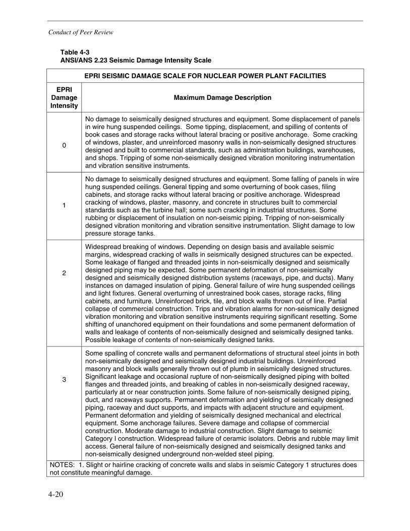
Conduct of Peer Review
4-20
Table 4-3 ANSI/ANS 2.23 Seismic Damage Intensity Scale
EPRI SEISMIC DAMAGE SCALE FOR NUCLEAR POWER PLANT FACILITIES
EPRI Damage Intensity
Maximum Damage Description
0
No damage to seismically designed structures and equipment. Some displacement of panels in wire hung suspended ceilings. Some tipping, displacement, and spilling of contents of book cases and storage racks without lateral bracing or positive anchorage. Some cracking of windows, plaster, and unreinforced masonry walls in non-seismically designed structures designed and built to commercial standards, such as administration buildings, warehouses, and shops. Tripping of some non-seismically designed vibration monitoring instrumentation and vibration sensitive instruments.
1
No damage to seismically designed structures and equipment. Some falling of panels in wire hung suspended ceilings. General tipping and some overturning of book cases, filing cabinets, and storage racks without lateral bracing or positive anchorage. Widespread cracking of windows, plaster, masonry, and concrete in structures built to commercial standards such as the turbine hall; some such cracking in industrial structures. Some rubbing or displacement of insulation on non-seismic piping. Tripping of non-seismically designed vibration monitoring and vibration sensitive instrumentation. Slight damage to low pressure storage tanks.
2
Widespread breaking of windows. Depending on design basis and available seismic margins, widespread cracking of walls in seismically designed structures can be expected. Some leakage of flanged and threaded joints in non-seismically designed and seismically designed piping may be expected. Some permanent deformation of non-seismically designed and seismically designed distribution systems (raceways, pipe, and ducts). Many instances on damaged insulation of piping. General failure of wire hung suspended ceilings and light fixtures. General overturning of unrestrained book cases, storage racks, filing cabinets, and furniture. Unreinforced brick, tile, and block walls thrown out of line. Partial collapse of commercial construction. Trips and vibration alarms for non-seismically designed vibration monitoring and vibration sensitive instruments requiring significant resetting. Some shifting of unanchored equipment on their foundations and some permanent deformation of walls and leakage of contents of non-seismically designed and seismically designed tanks. Possible leakage of contents of non-seismically designed tanks.
3
Some spalling of concrete walls and permanent deformations of structural steel joints in both non-seismically designed and seismically designed industrial buildings. Unreinforced masonry and block walls generally thrown out of plumb in seismically designed structures. Significant leakage and occasional rupture of non-seismically designed piping with bolted flanges and threaded joints, and breaking of cables in non-seismically designed raceway, particularly at or near construction joints. Some failure of non-seismically designed piping, duct, and raceways supports. Permanent deformation and yielding of seismically designed piping, raceway and duct supports, and impacts with adjacent structure and equipment. Permanent deformation and yielding of seismically designed mechanical and electrical equipment. Some anchorage failures. Severe damage and collapse of commercial construction. Moderate damage to industrial construction. Slight damage to seismic Category I construction. Widespread failure of ceramic isolators. Debris and rubble may limit access. General failure of non-seismically designed and seismically designed tanks and non-seismically designed underground non-welded steel piping.
NOTES: 1. Slight or hairline cracking of concrete walls and slabs in seismic Category 1 structures does not constitute meaningful damage.

5-1
5 CONCLUSIONS AND LESSONS LEARNED
The key conclusions and lessons learned from the EPRI independent peer review include the following:
• Comprehensive programs to address the effects of significant earthquakes at nuclear power plants should include three fundamental areas (as defined in ANSI/ANS Standard 2.23):
� Visual inspections
� Operability reviews and assessments
� Detailed Inspections/Testing/Analyses
This EPRI project included an independent review based on visual inspections for a representative number of key structures, systems and components. TEPCO has plans in place for operability reviews, detailed testing, and detailed inspections for SR items. The EPRI Peer Review Team was able to review selected specific plans and results to-date in meetings with key TEPCO personnel. The Peer Review Team finds these specific plans to be comprehensive. The overall assessment of the TEPCO NCO earthquake response program is that it is being conducted in a thorough and competent manner, consistent with, and in some areas more extensive than, the overall guidelines of the ANSI/ANS Standard.
• Based on the sampling visual inspections performed as a part of this peer review, KK safety-related (SR) structures, systems and components (SSCs) performed very well in response to the NCO earthquake. No significant damage was detected by visual inspection to the representative SR SSCs components reviewed.
• The Peer Review Team judges the following factors to have contributed to the excellent performance of SR SSCs:
� Supports and anchorage were typically observed to be very rugged with considerable seismic margin in their design
� Seismic system interactions (non-safety-related (NSR) component failures that caused failures/damage in SR components) were minimized based on anchorage of NSR components and appropriate maintenance practices for temporary configurations
� Japanese seismic design criteria include conservatisms in both the dynamic analysis as well as the static analysis approaches utilized in SSC designs
• Instances of damage were clearly identified for NSR SSCs that were reviewed. Examples of NSR damage included:
� House transformer fire
� Outside tank failures (buckling, attached piping failures and tank wall ruptures)
Conclusions and Lessons Learned
5-2
� Underground fire suppression piping failures
� Yard structure foundation failures and subsidence (liquefaction induced)
� Stack and transmission tower damage
� Pump house foundation and structure failures
� Water treatment component anchorage failures
� Falling control room ceiling items (light fixtures and ceiling diffusers)
While the results of these NSR failures and damage may not have had a critical SR ramification, it is the Peer Review Team’s observation that seismic upgrades could prevent issues that occurred following the earthquake with respect to communications, fire protection and available services. The damage to these NSR functions/components serves to divert the attention and availability of key TEPCO engineering/operations personnel and also sends a negative message to the public as to the safety of the overall nuclear plant operation. TEPCO could consider the advisability of invoking some level of seismic design for important NSR SSCs as part of the repairs and replacements of NSR SSCs damaged during the earthquake.
• The ANSI/ANS Standard 2.23 approach represents a valid framework for establishing a review program following an earthquake at a nuclear power plant. Earthquakes that significantly exceed the design basis for the plant in the frequency range which is potentially damaging (e.g., less than about 15 Hz range) should utilize the more stringent requirements delineated in the standard.
• Completion of the types of inspections, non-destructive examinations, operability reviews and testing of critical safety related SSCs that are planned is essential to the KK NCOE investigation program. Considering the lack of any significant physical or functional damage observed to date to SR SSCs, and if on-going investigations confirm this general finding, consideration could be given to a tiered investigation approach as suggested in ANSI/ANS Standard 2.23. Such an approach would employ systematic, structured sampling of representative and worst case items in lieu of 100% coverage where justified by the on-going results.
The TEPCO NCO earthquake response program includes implementation of appropriate seismic analyses to verify the NCO earthquake did not result in the exceedance of acceptable limits. TEPCO could consider use of the acceptance standards recommended in the seismic margin methodology and in the ANSI/ANS standard in these analyses (e.g. faulted condition type allowable stresses/displacements) utilizing median centered analytical approaches.
• This independent peer review considered the information available during the September visit to the KK plant. Some areas (such as detailed inspections and operability reviews of active SR items by TEPCO) were in progress at that time. Conduct of a follow-up peer review once the TEPCO post-earthquake evaluation has been completed to provide an independent assessment of the completed inspections, operability, and analytical reviews could be conducted as an enhancement to this peer review.

A-1
A PEER REVIEW WALKDOWN FORMS
The Independent Peer Review Team visually inspected a sampling of KK plant components in each of the 29 SSC categories defined in ANSI/ANS 2.2.3. The 59 components reviewed are documented in the following forms.
Table A-1 List of KK Equipment Reviewed
Form Equipment/
Structure Data Forms NP-6695
Component Page
Diesel Generator Start A-5 1 Air Compressors
Diesel Generator Start A-7
HPCF Air Handlers A-9 2 Air Handlers
Main Control Room A-11
HPCF Room A-13 3 Air Handling Ducts
Main Control Room A-15
Emergency DC Power A-17 4 Battery Racks
Emergency DC Power A-19
Fire Protection Piping at Diesel Oil Storage Tank A-21 5 Buried Pipe
Drinking Water Underground Piping A-23
C/A Chiller A-25 6 Chillers
HVAC Emergency Cooling Water (HECW) A-27
Control Room - Generator and Transformer Protection Relay Cabinet
A-29
7 Control and Instrumentation Cabinets
Auto Voltage Regulator (AVR) Panel A-31
ESS II (Emergency MCC Room B) A-33 8 Distribution Panels
Emergency Room Distribution Panel A-35
Cable Spreading Room A-37 9 Electric Raceways
Cable Spreading Room A-39

Peer Review Walkdown Forms
A-2
Form Equipment/
Structure Data Forms NP-6695
Component Page
Diesel Generator A-41 10 Engine-Generators
Diesel Generator A-43
Drywell Ventilation Fan A-45 11 Fans
Ceiling Mounted Fan (Diesel Room) A-47
Air Operated Valves in HCU/SCRAM System A-49 12
Fluid/Air/Motor-Operated Valves 4 Feedwater MOVs A-51
Seismic Accelerometers A-53 13 General Equipment
Switchyard A-55
RHR Heat Exchanger A-57 b14
High Pressure Tanks and Heat Exchangers High Pressure Feedwater Heat Exchanger A-59
Turbine Driven Reactor Feedwater A-61 15 Horizontal Pumps
"B" HPCF Core Flooding Pump A-63
General Instrument Rack A-65 16 Instrument Racks
Feedwater Pump Instrument Rack A-67
Diesel Oil Tank A-69
Demineralized Water and Caustic Storage Tanks A-71 17 Low Pressure Storage Tanks
Outdoor Filtrated Water Tank A-73
Emergency Diesel Generator Switchgear A-75 18 Low Voltage Switchgear
Emergency Diesel Generator Switchgear A-77
Metal Clad Switchgear 6.9 KV A-79 19
Medium Voltage Switchgear Metal Clad Switchgear 6.9 KV A-81
480V MCC 1C-1-5 A-83 20 Motor Control Centers
Turbine Bldg Radiation Monitor MCC A-85
PLR MG set #1 A-86 21 Motor Generators
PLR MG set #2 A-88
SLC Piping A-90 22 Piping
Reactor Bldg piping supported off wall A-92
HCU A-94 23 Primary Coolant System
HCU A-96
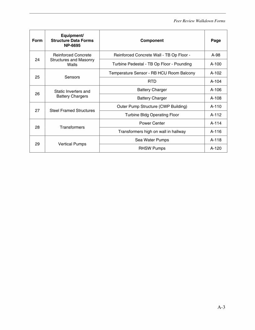
Peer Review Walkdown Forms
A-3
Form Equipment/
Structure Data Forms NP-6695
Component Page
Reinforced Concrete Wall - TB Op Floor - A-98 24
Reinforced Concrete Structures and Masonry
Walls Turbine Pedestal - TB Op Floor - Pounding A-100
Temperature Sensor - RB HCU Room Balcony A-102 25 Sensors
RTD A-104
Battery Charger A-106 26
Static Inverters and Battery Chargers Battery Charger A-108
Outer Pump Structure (CWP Building) A-110 27 Steel Framed Structures
Turbine Bldg Operating Floor A-112
Power Center A-114 28 Transformers
Transformers high on wall in hallway A-116
Sea Water Pumps A-118 29 Vertical Pumps
RHSW Pumps A-120


Kashiwazaki – Kariwa Nuclear Plant EPRI Independent Seismic Peer Review
September 24 – 28, 2007
EPRI NP-6695 Post-Shutdown Inspection and Test Checklist AIR COMPRESSORS – Diesel Generator (1-1) Check box if acceptable: 1. Check equipment anchorage/isolation mounts for damage; e.g., stretching or
loosening of anchor bolts or nuts; rocking or sliding of equipment.
Comments: Anchored to pad, no vibration isolators, anchorage adequate
2. Check for damage due to impact or earthquake induced flooding or spraying.
Comments: No interactions noted_______________________________
3. Check for excessive noise and/or vibration.
Comments: None noted by operators_____________________________
4. Check for air leaks if compressor is running continuously rather than cycling on and off. Comments: Cycling on and off__________________________________
5. Check for belt tightness and/or slippage; e.g., belt smoke/odor.
Comments: ________________________________________________
6. Check local alarms, breakers and protective devices for actuation/trips.
Comments: Nothing noted by operators who started it up___________________________ Walkdown Notes/Comments: _____________________________________________________________
_____________________________________________________________________________________
_____________________________________________________________________________________
_____________________________________________________________________________________
Picture Numbers: DSCF0040 (1-1a) DSCF0041 (1-1b)
___________________________________ ___________________________________ Greg Hardy James Johnson ARES Corporation James J. Johnson and Associates
___________________________________ ___________________________________ William Schmidt Jerry Kernaghan W. Schmidt Consulting Electrical Power Research Institute
Date: 9/26/07
KK Plant Unit #: 7
Plant Elevation: _______ meters
A-5

Kashiwazaki – Kariwa Nuclear Plant EPRI Independent Seismic Peer Review
September 24 – 28, 2007
EPRI NP-6695 Post-Shutdown Inspection and Test Checklist
DSCF0040 (1-1a)
DSCF0041 (1-1b)
A-6

Kashiwazaki – Kariwa Nuclear Plant EPRI Independent Seismic Peer Review
September 24 – 28, 2007
EPRI NP-6695 Post-Shutdown Inspection and Test Checklist AIR COMPRESSORS – Diesel Generator Air Compressor (1-2) Check box if acceptable: 1. Check equipment anchorage/isolation mounts for damage; e.g., stretching or
loosening of anchor bolts or nuts; rocking or sliding of equipment.
Comments: ________________________________________________
2. Check for damage due to impact or earthquake induced flooding or spraying.
Comments: ________________________________________________
3. Check for excessive noise and/or vibration.
Comments: Operator reported no noise/vibration___________________
4. Check for air leaks if compressor is running continuously rather than cycling on and off. Comments: None_____________________________________________
5. Check for belt tightness and/or slippage; e.g., belt smoke/odor.
Comments: _____________NA_________________________
6. Check local alarms, breakers and protective devices for actuation/trips.
Comments: ________________________________________________ Walkdown Notes/Comments: Operated following the earthquake , No problems found during the review_________________________________________________
_____________________________________________________________________________________
_____________________________________________________________________________________
_____________________________________________________________________________________
Picture Numbers: P1040518 (1-2a) CIMG4005 (1-2b) ___________________________________ ___________________________________ Greg Hardy James Johnson ARES Corporation James J. Johnson and Associates
___________________________________ ___________________________________ William Schmidt Jerry Kernaghan W. Schmidt Consulting Electrical Power Research Institute
Date: 09 / 27 / 07
KK Plant Unit #: 1
Plant Elevation: 2nd Floor
A-7

Kashiwazaki – Kariwa Nuclear Plant EPRI Independent Seismic Peer Review
September 24 – 28, 2007
EPRI NP-6695 Post-Shutdown Inspection and Test Checklist
P1040518 (1-2a)
CIMG4005 (1-2b)
A-8

Kashiwazaki – Kariwa Nuclear Plant EPRI Independent Seismic Peer Review
September 24 – 28, 2007
EPRI NP-6695 Post-Shutdown Inspection and Test Checklist AIR HANDLERS - HPCF (2-1) Check box if acceptable: 1. Check equipment anchorage/isolation mounts for damage; e.g., stretching
or loosening of anchor bolts or nuts; rocking or sliding of equipment.
Comments: Anchor bolts show no distress – no isolators____________
2. Check for damage to attached conduits and ground straps.
Comments: Only conduit with plenty of slack_____________________
3. Check for damage to air handler due to seismic loads imposed by attached ducts or tearing of fabric noise eliminators. Comments: No visible damage__________________________________
4. Check for damage due to impact or earthquake induced flooding or spraying Comments: Very little interaction potential, rugged components in area__
5. Check for belt tightness and/or slippage; e.g., belt smoke/odor
Comments: Direct drive – not sure if this has been operated____________
6. Check local alarms, breakers and protective devices for actuation/trips. Comments: N/A______________________________________________
Walkdown Notes/Comments: Very rugged design. No sign of any effects of the earthquake.____________
__TEPCO Guides not sure if this had been operated following the earthquake. _________________ _____________________________________________________________________________________
Picture Numbers: CIMG3881 (2-1a) CIMG3886 (2-1b) ___________________________________ ___________________________________ Greg Hardy James Johnson ARES Corporation James J. Johnson and Associates
___________________________________ ___________________________________ William Schmidt Jerry Kernaghan W. Schmidt Consulting Electrical Power Research Institute
Date: 09 / 26 / 07
KK Plant Unit #: 7 RB
Plant Elevation: B3 meters
A-9

Kashiwazaki – Kariwa Nuclear Plant EPRI Independent Seismic Peer Review
September 24 – 28, 2007
EPRI NP-6695 Post-Shutdown Inspection and Test Checklist
CIMG3881 (2-1a)
CIMG3886 (2-1b)
A-10

Kashiwazaki – Kariwa Nuclear Plant EPRI Independent Seismic Peer Review
September 24 – 28, 2007
EPRI NP-6695 Post-Shutdown Inspection and Test Checklist AIR HANDLERS – Class A HEPA Filter Air Handler for Main Control Room Check box if acceptable: (2-2) 1. Check equipment anchorage/isolation mounts for damage; e.g., stretching
or loosening of anchor bolts or nuts; rocking or sliding of equipment.
Comments: Welded tube steel frame to embed in floor______________
2. Check for damage to attached conduits and ground straps.
Comments: No problem______________________________________
3. Check for damage to air handler due to seismic loads imposed by attached ducts or tearing of fabric noise eliminators. Comments: No ducting problem________________________________
4. Check for damage due to impact or earthquake induced flooding or spraying Comments: No issue_________________________________________
5. Check for belt tightness and/or slippage; e.g., belt smoke/odor
Comments: Direct drive_______________________________________
6. Check local alarms, breakers and protective devices for actuation/trips. Comments: ________________________________________________
Walkdown Notes/Comments: Has not operated following the quake and needs to be checked for________ operability.___________________________________________________________________________
_____________________________________________________________________________________
Picture Numbers: IMG_0330 (2-2a) IMG_0335 (2-2b)
___________________________________ ___________________________________ Greg Hardy James Johnson ARES Corporation James J. Johnson and Associates
___________________________________ ___________________________________ William Schmidt Jerry Kernaghan W. Schmidt Consulting Electrical Power Research Institute
Date: 09 / 27 / 07
KK Plant Unit #: 1
Plant Elevation: 3F Combination Bldg
A-11

Kashiwazaki – Kariwa Nuclear Plant EPRI Independent Seismic Peer Review
September 24 – 28, 2007
EPRI NP-6695 Post-Shutdown Inspection and Test Checklist
IMG_0330 (2-2a)
IMG_0335 (2-2b)
A-12

Kashiwazaki – Kariwa Nuclear Plant EPRI Independent Seismic Peer Review
September 24 – 28, 2007
EPRI NP-6695 Post-Shutdown Inspection and Test Checklist AIR HANDLING DUCTS Check box if acceptable: 1. Check for deformation of dead weight supports and sway bracing.
Comments: A few rod supports observed between rigid supports. No evidence of any lateral movement or banging.
2. Check for damage to ducts at joints.
Comments: ________________________________________________
3. Check for damage to ducts at building joints and interfaces between buildings.
Comments: ________________________________________________
4. Check for damage due to impact or earthquake induced flooding or spraying. Comments: ________________________________________________
5. Check for tearing of fabric transitions/noise eliminators.
Comments: N/A .
6. Check for damage to internal filters and racks.
Comments: N/A . Walkdown Notes/Comments: Ducting inspected included Class A Control Room HVAC. NVD. . _________________________________________________________________ ____. ____________________________________________________________________________________
Picture Numbers: CIMG3871 (3-1a) CIMG3878 (3-1b)
___________________________________ ___________________________________ Greg Hardy James Johnson ARES Corporation James J. Johnson and Associates
___________________________________ ___________________________________ William Schmidt Jerry Kernaghan W. Schmidt Consulting Electrical Power Research Institute *Note 1: Locations in Cablespreading/Process Computer Room under Main Control Room in Control Building.
Date: 09 / 26 / 07
KK Plant Unit #: 6-7
Plant Elevation: Note 1 meters
A-13

Kashiwazaki – Kariwa Nuclear Plant EPRI Independent Seismic Peer Review
September 24 – 28, 2007
EPRI NP-6695 Post-Shutdown Inspection and Test Checklist
CIMG3871 (3-1a)
CIMG3878 (3-1b)
A-14
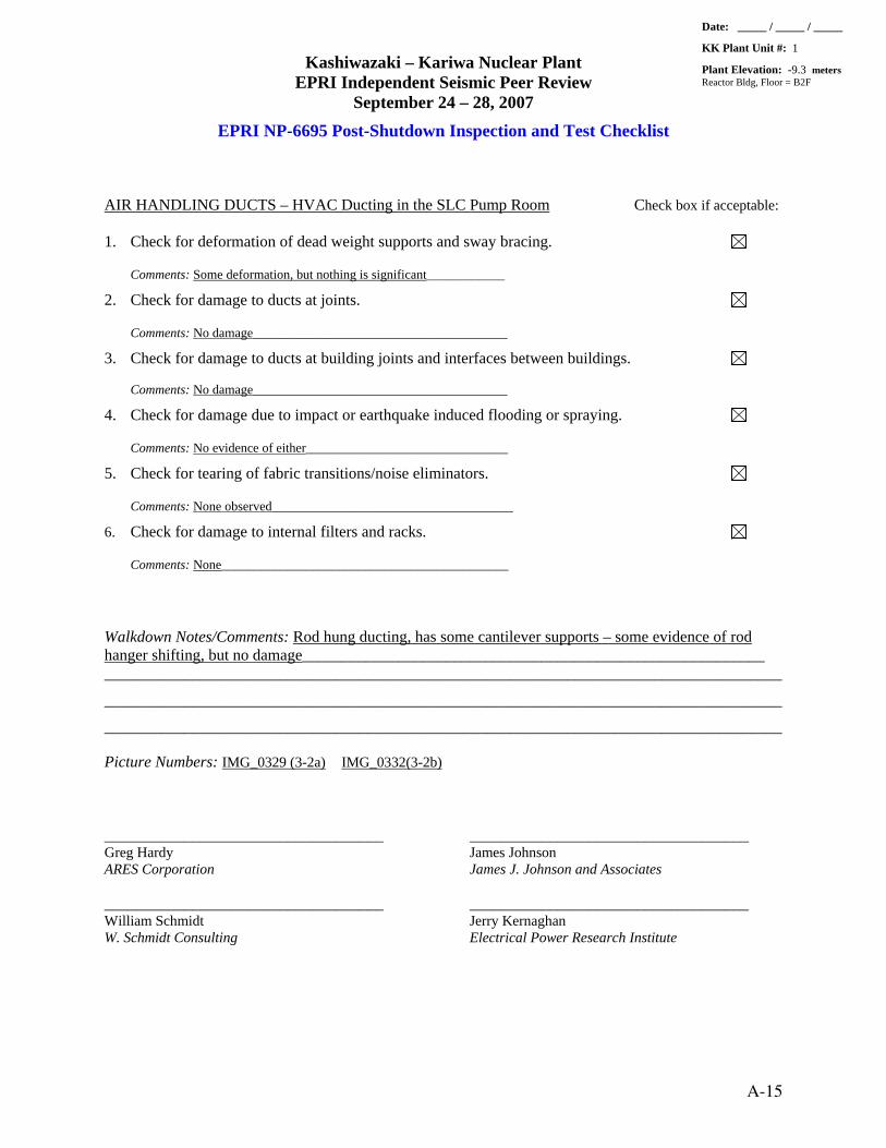
Kashiwazaki – Kariwa Nuclear Plant EPRI Independent Seismic Peer Review
September 24 – 28, 2007
EPRI NP-6695 Post-Shutdown Inspection and Test Checklist AIR HANDLING DUCTS – HVAC Ducting in the SLC Pump Room Check box if acceptable: 1. Check for deformation of dead weight supports and sway bracing.
Comments: Some deformation, but nothing is significant____________
2. Check for damage to ducts at joints.
Comments: No damage_______________________________________
3. Check for damage to ducts at building joints and interfaces between buildings.
Comments: No damage_______________________________________
4. Check for damage due to impact or earthquake induced flooding or spraying. Comments: No evidence of either_______________________________
5. Check for tearing of fabric transitions/noise eliminators.
Comments: None observed_____________________________________
6. Check for damage to internal filters and racks.
Comments: None____________________________________________ Walkdown Notes/Comments: Rod hung ducting, has some cantilever supports – some evidence of rod hanger shifting, but no damage__________________________________________________________
_____________________________________________________________________________________
_____________________________________________________________________________________
_____________________________________________________________________________________
Picture Numbers: IMG_0329 (3-2a) IMG_0332(3-2b) ___________________________________ ___________________________________ Greg Hardy James Johnson ARES Corporation James J. Johnson and Associates
___________________________________ ___________________________________ William Schmidt Jerry Kernaghan W. Schmidt Consulting Electrical Power Research Institute
Date: _____ / _____ / _____
KK Plant Unit #: 1
Plant Elevation: -9.3 meters Reactor Bldg, Floor = B2F
A-15

Kashiwazaki – Kariwa Nuclear Plant EPRI Independent Seismic Peer Review
September 24 – 28, 2007
EPRI NP-6695 Post-Shutdown Inspection and Test Checklist
IMG_0329 (3-2a)
IMG_0332 (3-2b)
A-16

Kashiwazaki – Kariwa Nuclear Plant EPRI Independent Seismic Peer Review
September 24 – 28, 2007
EPRI NP-6695 Post-Shutdown Inspection and Test Checklist BATTERY RACKS Check box if acceptable: 1. Check battery rack anchorage for damage; e.g., stretching or
loosening of anchor bolts or nuts; evidence of rocking or sliding of racks.
Comments: Angle frame system – rugged, no damage_______________
2. Check for distortion of rack structure.
Comments: None____________________________________________
3. Check for evidence of rocking or sliding of batteries on the racks, buckling or distortion of the bus bars, condition of the spacers between batteries. Comments: None____________________________________________
4. Check for damage due to impact or earthquake induced flooding or spraying. Comments: None____________________________________________
5. Check buses/cables/ground straps for damage, distortion or chafing.
Comments: None____________________________________________
6. Check local alarms, breakers and protective devices for actuation/trips.
Comments: None____________________________________________
7. Function check. Walkdown Notes/Comments: Similar batteries and racks to Unit 1. No evidence of damage or anomalies_ to either the rack or the battery.___________________________________________________________
_____________________________________________________________________________________
Picture Numbers: DSCF0006 (4-1a) P1040506 (4-1b)
___________________________________ ___________________________________ Greg Hardy James Johnson ARES Corporation James J. Johnson and Associates
___________________________________ ___________________________________ William Schmidt Jerry Kernaghan W. Schmidt Consulting Electrical Power Research Institute
Date: _09__ / _26_ / _07_
KK Plant Unit #: 1
Plant Elevation: __B1F__ meters
A-17

Kashiwazaki – Kariwa Nuclear Plant EPRI Independent Seismic Peer Review
September 24 – 28, 2007
EPRI NP-6695 Post-Shutdown Inspection and Test Checklist
DSCF0006 (4-1a)
P1040506 (4-1b)
A-18
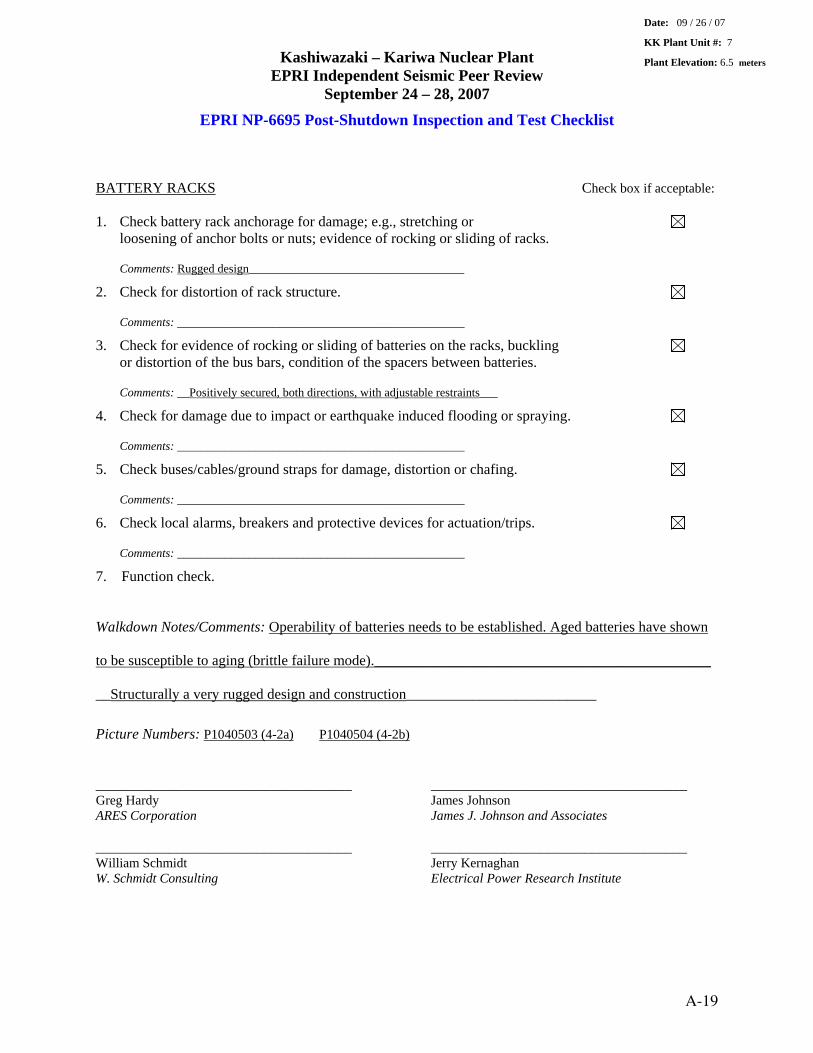
Kashiwazaki – Kariwa Nuclear Plant EPRI Independent Seismic Peer Review
September 24 – 28, 2007
EPRI NP-6695 Post-Shutdown Inspection and Test Checklist BATTERY RACKS Check box if acceptable: 1. Check battery rack anchorage for damage; e.g., stretching or
loosening of anchor bolts or nuts; evidence of rocking or sliding of racks.
Comments: Rugged design____________________________________
2. Check for distortion of rack structure.
Comments: ________________________________________________
3. Check for evidence of rocking or sliding of batteries on the racks, buckling or distortion of the bus bars, condition of the spacers between batteries. Comments: __Positively secured, both directions, with adjustable restraints___
4. Check for damage due to impact or earthquake induced flooding or spraying. Comments: ________________________________________________
5. Check buses/cables/ground straps for damage, distortion or chafing.
Comments: ________________________________________________
6. Check local alarms, breakers and protective devices for actuation/trips.
Comments: ________________________________________________
7. Function check. Walkdown Notes/Comments: Operability of batteries needs to be established. Aged batteries have shown to be susceptible to aging (brittle failure mode).______________________________________________ __Structurally a very rugged design and construction__________________________
Picture Numbers: P1040503 (4-2a) P1040504 (4-2b) ___________________________________ ___________________________________ Greg Hardy James Johnson ARES Corporation James J. Johnson and Associates
___________________________________ ___________________________________ William Schmidt Jerry Kernaghan W. Schmidt Consulting Electrical Power Research Institute
Date: 09 / 26 / 07
KK Plant Unit #: 7
Plant Elevation: 6.5 meters
A-19

Kashiwazaki – Kariwa Nuclear Plant EPRI Independent Seismic Peer Review
September 24 – 28, 2007
EPRI NP-6695 Post-Shutdown Inspection and Test Checklist
P1040503 (4-2a)
P1040504 (4-2b)
A-20

Kashiwazaki – Kariwa Nuclear Plant EPRI Independent Seismic Peer Review
September 24 – 28, 2007
EPRI NP-6695 Post-Shutdown Inspection and Test Checklist BURIED PIPE – at Unit 1 Diesel Oil Storage Tank (5-1) Check box if acceptable: 1. Check for damage or leakage at pipe interface with buildings and tanks. No
Comments: Damage at the interface of the tank due to 1 meter vertical failure of soil
2. Fire main leakage will be evidenced by self excavation and actuation of back up fire pumps. Comments: ____________________NA______________________
3. Fire mains, service and circulating water piping, especially dead legs, are susceptible to buildings of corrosion and growths which are knocked loose by earthquake motion. These loosened accumulations can clog screens and small diameter pipes such as fire hose hydrants. Checks for clogging and flushing of pipe mains are necessary. Comments: Piping flow restrictions not know at the time of the walkdown review
Walkdown Notes/Comments: Obvious soil failures/liquefaction caused failures. Fire protection system not safety related._________________________________________________________________________
_____________________________________________________________________________________
Picture Numbers: P1040385 (5-1a) P1040376 (5-1b)
___________________________________ ___________________________________ Greg Hardy James Johnson ARES Corporation James J. Johnson and Associates
___________________________________ ___________________________________ William Schmidt Jerry Kernaghan W. Schmidt Consulting Electrical Power Research Institute
Date: _09_ / _27_ / _07
KK Plant Unit #: ___1_____
Plant Elevation: _______ meters
A-21
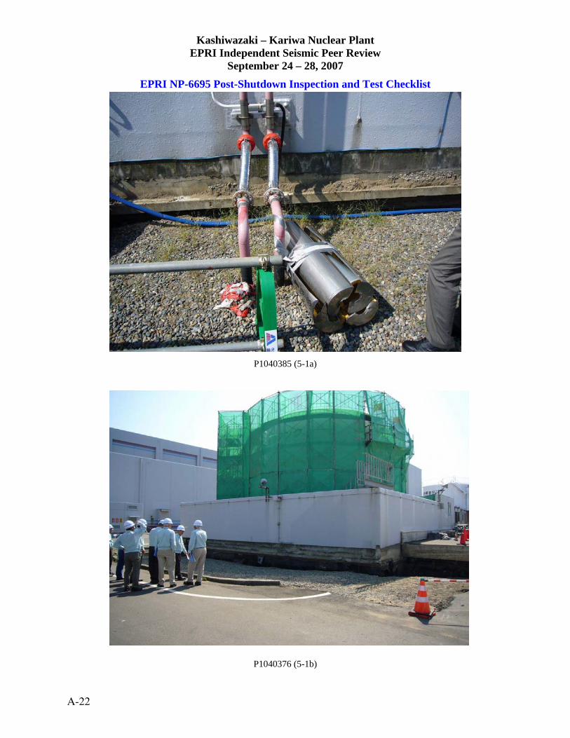
Kashiwazaki – Kariwa Nuclear Plant EPRI Independent Seismic Peer Review
September 24 – 28, 2007
EPRI NP-6695 Post-Shutdown Inspection and Test Checklist
P1040385 (5-1a)
P1040376 (5-1b)
A-22

Kashiwazaki – Kariwa Nuclear Plant EPRI Independent Seismic Peer Review
September 24 – 28, 2007
EPRI NP-6695 Post-Shutdown Inspection and Test Checklist BURIED PIPE (5-2) Check box if acceptable: 1. Check for damage or leakage at pipe interface with buildings and tanks.
Comments: Failure occurred – cause likely to have been ground failure_
2. Fire main leakage will be evidenced by self excavation and actuation of back up fire pumps. Comments: N/A_____________________________________________
3. Fire mains, service and circulating water piping, especially dead legs, are susceptible to buildings of corrosion and growths which are knocked loose by earthquake motion. These loosened accumulations can clog screens and small diameter pipes such as fire hose hydrants. Checks for clogging and flushing of pipe mains are necessary. Comments: N/A – Pipe failures precluded flushing of buried piping______
Walkdown Notes/Comments: Failure also occurred at tank due to soil settlement.____________________ _____________________________________________________________________________________
_____________________________________________________________________________________
Picture Numbers: DSCF0045 (5-2a) CIMG3805 (5-2b)
___________________________________ ___________________________________ Greg Hardy James Johnson ARES Corporation James J. Johnson and Associates
___________________________________ ___________________________________ William Schmidt Jerry Kernaghan W. Schmidt Consulting Electrical Power Research Institute
Date: 09 / 25 / 07
KK Plant Unit #: ___________
Plant Elevation: Outside meters
A-23

Kashiwazaki – Kariwa Nuclear Plant EPRI Independent Seismic Peer Review
September 24 – 28, 2007
EPRI NP-6695 Post-Shutdown Inspection and Test Checklist
DSCF0045 (5-2a)
CIMG3805 (5-2b)
A-24

Kashiwazaki – Kariwa Nuclear Plant EPRI Independent Seismic Peer Review
September 24 – 28, 2007
EPRI NP-6695 Post-Shutdown Inspection and Test Checklist CHILLERS – Class C (ISR2050, 3000 RPM) (6-1) Check box if acceptable: 1. Check equipment anchorage/isolation mounts for damage; e.g., stretching or
loosening of anchor bolts or nuts; rocking or sliding of equipment.
Comments: Hard mounted____________________________________
2. Check for damage to attached conduits and ground straps.
Comments: No problem______________________________________
3. Check for leakage or damage to chiller components due to seismic loads imposed by attached ducts and piping. Comments: ________________________________________________
4. Check for damage due to impact or earthquake induced flooding or spraying. Comments: No problem_______________________________________
5. Check for belt tightness and/or slippage; e.g., belt smoke/odor.
Comments: N/A_____________________________________________
6. Check local alarms, breakers and protective devices for actuation/trips.
Comments: Mounted on sturdy braced panel frame__________________
7. Check for refrigerant leakage.
Comments: _________________________________________________ Walkdown Notes/Comments: Chiller was operated and TEPCO reported on damage or malfunctions
_____________________________________________________________________________________
_____________________________________________________________________________________
_____________________________________________________________________________________
Picture Numbers: DSCF0044 (6-1a) DSCF0045 (6-1b)
___________________________________ ___________________________________ Greg Hardy James Johnson ARES Corporation James J. Johnson and Associates
___________________________________ ___________________________________ William Schmidt Jerry Kernaghan W. Schmidt Consulting Electrical Power Research Institute
Date: 09 / 26 / 07
KK Plant Unit #: 1
Plant Elevation: 3F meters Combination Bldg
A-25

Kashiwazaki – Kariwa Nuclear Plant EPRI Independent Seismic Peer Review
September 24 – 28, 2007
EPRI NP-6695 Post-Shutdown Inspection and Test Checklist
DSCF0044 (6-1a)
DSCF0045 (6-1b)
A-26

Kashiwazaki – Kariwa Nuclear Plant EPRI Independent Seismic Peer Review
September 24 – 28, 2007
EPRI NP-6695 Post-Shutdown Inspection and Test Checklist CHILLERS – HECW Chiller (6-2) Check box if acceptable: 1. Check equipment anchorage/isolation mounts for damage; e.g., stretching or
loosening of anchor bolts or nuts; rocking or sliding of equipment.
Comments: Vibration isolators not present, huge anchor bolts show no distress
2. Check for damage to attached conduits and ground straps.
Comments: All attachments adequate___________________________
3. Check for leakage or damage to chiller components due to seismic loads imposed by attached ducts and piping. Comments: ________________________________________________
4. Check for damage due to impact or earthquake induced flooding or spraying. Comments: None found_______________________________________
5. Check for belt tightness and/or slippage; e.g., belt smoke/odor.
Comments: N/A_____________________________________________
6. Check local alarms, breakers and protective devices for actuation/trips.
Comments: None present______________________________________
7. Check for refrigerant leakage.
Comments: _________________________________________________ Walkdown Notes/Comments: Chillers were operating (two units) at the time of the walkdown, operator__ reported that no problems or anomalies existed for either chiller._________________________________
_____________________________________________________________________________________
Picture Numbers: P1040552 (6-2a) P1040553 (6-2b)
___________________________________ ___________________________________ Greg Hardy James Johnson ARES Corporation James J. Johnson and Associates
___________________________________ ___________________________________ William Schmidt Jerry Kernaghan W. Schmidt Consulting Electrical Power Research Institute
Date: 09 / 26 / 07
KK Plant Unit #: 7
Plant Elevation: _______ meters
A-27

Kashiwazaki – Kariwa Nuclear Plant EPRI Independent Seismic Peer Review
September 24 – 28, 2007
EPRI NP-6695 Post-Shutdown Inspection and Test Checklist
P1040552 (6-2a)
P1040553 (6-2b)
A-28

Kashiwazaki – Kariwa Nuclear Plant EPRI Independent Seismic Peer Review
September 24 – 28, 2007
EPRI NP-6695 Post-Shutdown Inspection and Test Checklist CONTROL AND INSTRUMENTATION CABINETS Check box if acceptable: Generator & Transformer Protection Relay Cabinet/Control Room Cabinet (7-1) 1. Check equipment anchorage for damage; e.g., stretching or loosening
of anchor bolts or nuts; rocking or sliding of equipment.
Comments: Rugged bolts attach to I-beams system on floor_________
2. Check for distortion of panel structure.
Comments: No distortion____________________________________
3. Check for damage to attached conduit and ground straps.
Comments: OK____________________________________________
4. Check to see that instruments, gages, controls, and other equipment mounted to panels are secure and undamaged. Comments: Nothing appears out of ordinary_____________________
5. Check for damage due to impact or earthquake induced flooding or spraying.
Comments: _______________________________________________
6. Check local alarms, breakers and protective devices for actuation/trips.
Comments: ________________________________________________
7. Reset any trips. Investigate re-trips after reset.
Comments: Operator reports no trips resulted from the earthquake to the generator & transformer
Walkdown Notes/Comments: Judged OK____________________________________________________ _____________________________________________________________________________________
Picture Numbers: P1040507 (7-1a) ______ P1040521 (7-1b) __________
___________________________________ ___________________________________ Greg Hardy James Johnson ARES Corporation James J. Johnson and Associates
___________________________________ ___________________________________ William Schmidt Jerry Kernaghan W. Schmidt Consulting Electrical Power Research Institute
Date: 09 / 27 / 07
KK Plant Unit #: 1
Plant Elevation: 2 meters
A-29

Kashiwazaki – Kariwa Nuclear Plant EPRI Independent Seismic Peer Review
September 24 – 28, 2007
EPRI NP-6695 Post-Shutdown Inspection and Test Checklist
P1040507 (7-1a)
P1040521 (7-1b)
A-30

Kashiwazaki – Kariwa Nuclear Plant EPRI Independent Seismic Peer Review
September 24 – 28, 2007
EPRI NP-6695 Post-Shutdown Inspection and Test Checklist CONTROL AND INSTRUMENTATION CABINETS - (7-2) Check box if acceptable: Auto Voltage Regulator Control Cabinet for EDG 1. Check equipment anchorage for damage; e.g., stretching or loosening
of anchor bolts or nuts; rocking or sliding of equipment.
Comments: ____Bolted to embedded plate________
2. Check for distortion of panel structure.
Comments: ________________________________________________
3. Check for damage to attached conduit and ground straps.
Comments: _4” Flex Conduit Well Supported- Strapped to box beam
4. Check to see that instruments, gages, controls, and other equipment mounted to panels are secure and undamaged. Comments: N/A________________________________________________
5. Check for damage due to impact or earthquake induced flooding or spraying.
Comments: ________________________________________________
6. Check local alarms, breakers and protective devices for actuation/trips.
Comments: N/A_____________________________________________
7. Reset any trips. Investigate re-trips after reset.
Comments: N/A_____________________________________________ Walkdown Notes/Comments: NVD. ________________________________________________________
__Class A Cabinet, ¼ inch steel metal frame, very rugged, not operation at the time of the earthquake,._
____ Inspection being conducted at the time.________________________________________________
Picture Numbers: P1040546 (7-2a) P1040545 (7-2b)
___________________________________ ___________________________________ Greg Hardy James Johnson ARES Corporation James J. Johnson and Associates
___________________________________ ___________________________________ William Schmidt Jerry Kernaghan W. Schmidt Consulting Electrical Power Research Institute
Date: 09 / 27 / 07
KK Plant Unit #: 1
Plant Elevation: EDG Control Room RB11
A-31

Kashiwazaki – Kariwa Nuclear Plant EPRI Independent Seismic Peer Review
September 24 – 28, 2007
EPRI NP-6695 Post-Shutdown Inspection and Test Checklist
P1040546 (7-2a)
P1040545 (7-2b)
A-32

Kashiwazaki – Kariwa Nuclear Plant EPRI Independent Seismic Peer Review
September 24 – 28, 2007
EPRI NP-6695 Post-Shutdown Inspection and Test Checklist DISTRIBUTION PANELS – ESSII (8-1) Check box if Emergency MCC Room B 1. Check equipment anchorage for damage; e.g., stretching or loosening
of anchor bolts or nuts; rocking or sliding of equipment.
Comments: Welded to wall embed______________________________
2. Check for damage to attached conduit and ground straps.
Comments: ________________________________________________
3. Check for distortion of cabinet structure. Comments: No______________________________________________
4. Open cabinet, check to see that all internally mounted components are secure and undamaged. Comments: ________________________________________________
5. Check for damage due to impact or earthquake induced flooding or spraying.
Comments: None____________________________________________
6. Reset any tripped breakers. Investigate any re-trips after reset.
Comments: TEPCO Operator reported no trips_____________________________ Walkdown Notes/Comments: 125 V Panel Breakers___________________________________________
_______Rugged and experienced no damage or anomalies due to the NCO earthquake______________
_____________________________________________________________________________________
_____________________________________________________________________________________
Picture Numbers: P1040520 (8-1a) P1040519 (8-1b) ___________________________________ ___________________________________ Greg Hardy James Johnson ARES Corporation James J. Johnson and Associates
___________________________________ ___________________________________ William Schmidt Jerry Kernaghan W. Schmidt Consulting Electrical Power Research Institute
Date: 09 / 27 / 07
KK Plant Unit #: 1
Plant Elevation: _______ meters Combination Bldg
A-33

Kashiwazaki – Kariwa Nuclear Plant EPRI Independent Seismic Peer Review
September 24 – 28, 2007
EPRI NP-6695 Post-Shutdown Inspection and Test Checklist
P1040520 (8-1a)
P1040519 (8-1b)
A-34

Kashiwazaki – Kariwa Nuclear Plant EPRI Independent Seismic Peer Review
September 24 – 28, 2007
EPRI NP-6695 Post-Shutdown Inspection and Test Checklist DISTRIBUTION PANELS – Distribution Panel, Emergency Room (8-2) Check box if acceptable: 1. Check equipment anchorage for damage; e.g., stretching or loosening
of anchor bolts or nuts; rocking or sliding of equipment.
Comments: Secured to well embedment’s_________________________
2. Check for damage to attached conduit and ground straps.
Comments: ________________________________________________
3. Check for distortion of cabinet structure. Comments: ________________________________________________
4. Open cabinet, check to see that all internally mounted components are secure and undamaged. Comments: Could not open____________________________________
5. Check for damage due to impact or earthquake induced flooding or spraying.
Comments: ________________________________________________
6. Reset any tripped breakers. Investigate any re-trips after reset.
Comments: N/A_____________________________________________ Walkdown Notes/Comments: NVD.________________________________________________________ _____________________________________________________________________________________
_____________________________________________________________________________________
Picture Numbers: CIMG3988 (8-2a no b) ___________________________________ ___________________________________ Greg Hardy James Johnson ARES Corporation James J. Johnson and Associates
___________________________________ ___________________________________ William Schmidt Jerry Kernaghan W. Schmidt Consulting Electrical Power Research Institute
Date: 09 / 27 / 07
KK Plant Unit #: 1
Plant Elevation: Combination Bldg
A-35

Kashiwazaki – Kariwa Nuclear Plant EPRI Independent Seismic Peer Review
September 24 – 28, 2007
EPRI NP-6695 Post-Shutdown Inspection and Test Checklist
CIMG3988 (8-2a no b)
A-36

Kashiwazaki – Kariwa Nuclear Plant EPRI Independent Seismic Peer Review
September 24 – 28, 2007
EPRI NP-6695 Post-Shutdown Inspection and Test Checklist ELECTRIC RACEWAYS – Cable and Conduct Raceways and Supports (9-1) Check box if acceptable: 1. Check for deformation of dead weight supports and sway bracing.
Comments: Rugged shed cantilever bracket, braced frame supports. Also floor-to-ceiling.
2. Check for damage to cables at building joints and interfaces between buildings. Comments: ________________________________________________
3. Check for damage due to impact or earthquake induced flooding or spraying. Comments: ________________________________________________
Walkdown Notes/Comments: NVD.____Very Rugged supports and design._____________________
_____________________________________________________________________________________
_____________________________________________________________________________________
_____________________________________________________________________________________
Picture Numbers: CIMG3991 (9-1a) CIMG3990 (9-1b) ___________________________________ ___________________________________ Greg Hardy James Johnson ARES Corporation James J. Johnson and Associates
___________________________________ ___________________________________ William Schmidt Jerry Kernaghan W. Schmidt Consulting Electrical Power Research Institute *Note 1: General area of Lower Control Room/Cable Spreading Room
Date: 09 / 27 / 07
KK Plant Unit #: 1
Plant Elevation: Note 1
A-37

Kashiwazaki – Kariwa Nuclear Plant EPRI Independent Seismic Peer Review
September 24 – 28, 2007
EPRI NP-6695 Post-Shutdown Inspection and Test Checklist
CIMG3991 (9-1a)
CIMG3990 (9-1b)
A-38

Kashiwazaki – Kariwa Nuclear Plant EPRI Independent Seismic Peer Review
September 24 – 28, 2007
EPRI NP-6695 Post-Shutdown Inspection and Test Checklist ELECTRIC RACEWAYS – Process Control Room (9-2) Check box if acceptable: (Cable Spreading Room) 1. Check for deformation of dead weight supports and sway bracing.
Comments: Load only a small fraction of support capacity___________
2. Check for damage to cables at building joints and interfaces between buildings. Comments: Joints between rooms acceptable______________________
3. Check for damage due to impact or earthquake induced flooding or spraying. Comments: Cable trays are so well supported no interactions occurred.__
Walkdown Notes/Comments: Trays supported with large box beams. Well supported cables and trays.___ ____________________________________________________________________________________
_____________________________________________________________________________________
Picture Numbers: DSCF0016 (9-2a) DSCF0042 (9-2b) ___________________________________ ___________________________________ Greg Hardy James Johnson ARES Corporation James J. Johnson and Associates
___________________________________ ___________________________________ William Schmidt Jerry Kernaghan W. Schmidt Consulting Electrical Power Research Institute
Date: 09 / 26 / 07
KK Plant Unit #: 7
Plant Elevation: 12.3 meters Control Bldg
A-39

Kashiwazaki – Kariwa Nuclear Plant EPRI Independent Seismic Peer Review
September 24 – 28, 2007
EPRI NP-6695 Post-Shutdown Inspection and Test Checklist
DSCF0016 (9-2a)
DSCF0042 (9-2b)
A-40

Kashiwazaki – Kariwa Nuclear Plant EPRI Independent Seismic Peer Review
September 24 – 28, 2007
EPRI NP-6695 Post-Shutdown Inspection and Test Checklist ENGINE-GENERATORS – Diesel Generator Unit 1 (10-1) Check box if acceptable: 1. Check equipment anchorage/isolation mounts for damage; e.g., stretching
or loosening of anchor bolts or nuts; rocking or sliding of equipment. Comments: No damage_______________________________________
2. Check for damage to attached piping, ducts, conduits and ground straps.
Comments: Attached lines acceptable, slack in lines________________
3. Check for noise and/or vibration due to misalignment between engine and generator, especially if not mounted to a common base. Comments: ________________________________________________
4. Check for damage due to impact or earthquake induced flooding or spraying.
Comments: No evidence of any II/I of any kind____________________
5. Check local alarms, breakers and protective devices for actuation/trips.
Comments: ________________________________________________ Walkdown Notes/Comments: Surveillance test – started up and operated___________________________
__EDG Control Panel, all attached lines, voltage regulatory and field breaker all intact with no visible
damage.____________________________________________________________________________
_____________________________________________________________________________________
Picture Numbers: DSCF0033 (10-1a) DSCF0041 (10-1b) ___________________________________ ___________________________________ Greg Hardy James Johnson ARES Corporation James J. Johnson and Associates
___________________________________ ___________________________________ William Schmidt Jerry Kernaghan W. Schmidt Consulting Electrical Power Research Institute
Date: _9__ / __27 / _07__
KK Plant Unit #: __1______
Plant Elevation: _______ meters
A-41

Kashiwazaki – Kariwa Nuclear Plant EPRI Independent Seismic Peer Review
September 24 – 28, 2007
EPRI NP-6695 Post-Shutdown Inspection and Test Checklist
DSCF0033 (10-1a)
DSCF0041 (10-1b)
A-42

Kashiwazaki – Kariwa Nuclear Plant EPRI Independent Seismic Peer Review
September 24 – 28, 2007
EPRI NP-6695 Post-Shutdown Inspection and Test Checklist ENGINE-GENERATORS – Diesel Generator (10-2) Check box if acceptable: 1. Check equipment anchorage/isolation mounts for damage; e.g., stretching
or loosening of anchor bolts or nuts; rocking or sliding of equipment. Comments: Anchorage rugged and no anomalies__________________
2. Check for damage to attached piping, ducts, conduits and ground straps.
Comments: No concerns identified_____________________________
3. Check for noise and/or vibration due to misalignment between engine and generator, especially if not mounted to a common base. Comments: ________________________________________________
4. Check for damage due to impact or earthquake induced flooding or spraying.
Comments: None____________________________________________
5. Check local alarms, breakers and protective devices for actuation/trips.
Comments: Diesel was operated following the earthquake and operated properly. Walkdown Notes/Comments: Diesel components rugged, no impacts or distortions.__________________
_____________________________________________________________________________________
_____________________________________________________________________________________
Picture Numbers: DSCF0033 (10-2a no b) ___________________________________ ___________________________________ Greg Hardy James Johnson ARES Corporation James J. Johnson and Associates
___________________________________ ___________________________________ William Schmidt Jerry Kernaghan W. Schmidt Consulting Electrical Power Research Institute
Date: 09 / 26 / 07
KK Plant Unit #: 7
Plant Elevation: _______ meters
A-43

Kashiwazaki – Kariwa Nuclear Plant EPRI Independent Seismic Peer Review
September 24 – 28, 2007
EPRI NP-6695 Post-Shutdown Inspection and Test Checklist
DSCF0033 (10-2a no b)
A-44

Kashiwazaki – Kariwa Nuclear Plant EPRI Independent Seismic Peer Review
September 24 – 28, 2007
EPRI NP-6695 Post-Shutdown Inspection and Test Checklist FANS – Drywell Ventilation Fans Check box if acceptable: 1. Check equipment anchorage/isolation mounts for damage; e.g., stretching or
loosening of anchor bolts or nuts; rocking or sliding of equipment.
Comments: Not visible, but fans operating normally________________
2. Check for damage to attached conduit and ground straps.
Comments: Ground strap not visible_____________________________
3. Check for damage or distortion to fan housing or tearing of fabric noise eliminators due to seismic loads imposed by attached ducts.
Comments: ________________________________________________
4. Check for evidence of excessive fan vibration and/or noise. May be an indication of misalignment between the motor and fan shafts.
Comments: Appeared to be operating normally_____________________
5. Check clearance between fan wheel and housing.
Comments: N/A______________________________________________
6. Check for damage due to impact or earthquake induced flooding or spraying
Comments: NVD_____________________________________________
7. Check for belt tightness and/or slippage; e.g., belt smoke/odor
Comments: N/A______________________________________________
8. Check local alarms, breakers and protective devices for actuation/trips.
Comments: N/A_______________________________________________ Walkdown Notes/Comments: No signs of any distress or earthquake effects in D/W__________________
_____________________________________________________________________________________
_____________________________________________________________________________________
Picture Numbers: P1040483 (11-1a) P1040485 (11-1b) ___________________________________ ___________________________________ Greg Hardy James Johnson ARES Corporation James J. Johnson and Associates
___________________________________ ___________________________________ William Schmidt Jerry Kernaghan W. Schmidt Consulting Electrical Power Research Institute
Date: 09 / 27 / 07
KK Plant Unit #: 1
Plant Elevation: RB-Drywell
A-45

Kashiwazaki – Kariwa Nuclear Plant EPRI Independent Seismic Peer Review
September 24 – 28, 2007
EPRI NP-6695 Post-Shutdown Inspection and Test Checklist
P1040483 (11-1a)
P1040485 (11-1b)
A-46

Kashiwazaki – Kariwa Nuclear Plant EPRI Independent Seismic Peer Review
September 24 – 28, 2007
EPRI NP-6695 Post-Shutdown Inspection and Test Checklist FANS – Ceiling Mounted Fans in Diesel Room (11-2) Check box if acceptable: 1. Check equipment anchorage/isolation mounts for damage; e.g., stretching or
loosening of anchor bolts or nuts; rocking or sliding of equipment.
Comments: No isolation mounts, rugged anchorage________________
2. Check for damage to attached conduit and ground straps.
Comments: None____________________________________________
3. Check for damage or distortion to fan housing or tearing of fabric noise eliminators due to seismic loads imposed by attached ducts.
Comments: None____________________________________________
4. Check for evidence of excessive fan vibration and/or noise. May be an indication of Mis-alignment between the motor and fan shafts.
Comments: Fan was not operating while being reviewed – thus unknown
5. Check clearance between fan wheel and housing.
Comments: ________________________________________________
6. Check for damage due to impact or earthquake induced flooding or spraying
Comments: None____________________________________________
7. Check for belt tightness and/or slippage; e.g., belt smoke/odor
Comments: N/A_____________________________________________
8. Check local alarms, breakers and protective devices for actuation/trips.
Comments: N/A_____________________________________________ Walkdown Notes/Comments: Visual inspection revealed fan survived earthquake with no anomalies_____
_____________________________________________________________________________________
_____________________________________________________________________________________
_____________________________________________________________________________________
Picture Numbers: P1040510 (11-2a) P1040513 (11-2b) ___________________________________ ___________________________________ Greg Hardy James Johnson ARES Corporation James J. Johnson and Associates
___________________________________ ___________________________________ William Schmidt Jerry Kernaghan W. Schmidt Consulting Electrical Power Research Institute
Date: 09 / 26 / 07
KK Plant Unit #: 7
Plant Elevation: _______ meters
A-47

Kashiwazaki – Kariwa Nuclear Plant EPRI Independent Seismic Peer Review
September 24 – 28, 2007
EPRI NP-6695 Post-Shutdown Inspection and Test Checklist
P1040510 (11-2a)
P1040513 (11-2b)
A-48

Kashiwazaki – Kariwa Nuclear Plant EPRI Independent Seismic Peer Review
September 24 – 28, 2007
EPRI NP-6695 Post-Shutdown Inspection and Test Checklist FLUID/AIR/MOTOR-OPERATED VALVES – Check box if acceptable: Air-operated valves in HCUs/scram control valves 1. Check for damage or distortion at attachment of operator to valve body.
Comments: ________________________________________________
2. Check for damage to attached conduit/tubing, ground straps.
Comments: ________________________________________________
3. Check for damage due to impact or earthquake induced flooding or spraying. Comments: ________________________________________________
4. Check local alarms/indicators/protective devices for actuations/trips.
Comments: N/A_____________________________________________
5. Stroke valve in both directions to check operation.
Comments: N/A_____________________________________________ Walkdown Notes/Comments: Undisturbed condition. NVD___________________________ . displacement.__________________________________________________________________________
_____________________________________________________________________________________
Picture Numbers: CIMG3893 (12-1a) CIMG3894 (12-1b) ___________________________________ ___________________________________ Greg Hardy James Johnson ARES Corporation James J. Johnson and Associates
___________________________________ ___________________________________ William Schmidt Jerry Kernaghan W. Schmidt Consulting Electrical Power Research Institute
Date: 09 / 26 / 07
KK Plant Unit #: 7
Plant Elevation: RB meters
A-49

Kashiwazaki – Kariwa Nuclear Plant EPRI Independent Seismic Peer Review
September 24 – 28, 2007
EPRI NP-6695 Post-Shutdown Inspection and Test Checklist
CIMG3893 (12-1a)
CIMG3894 (12-1b)
A-50

Kashiwazaki – Kariwa Nuclear Plant EPRI Independent Seismic Peer Review
September 24 – 28, 2007
EPRI NP-6695 Post-Shutdown Inspection and Test Checklist FLUID/AIR/MOTOR-OPERATED VALVES – Check box if acceptable: 4 FW MOVs 1. Check for damage or distortion at attachment of operator to valve body.
Comments: ________________________________________________
2. Check for damage to attached conduit/tubing, ground straps.
Comments: ________________________________________________
3. Check for damage due to impact or earthquake induced flooding or spraying. Comments: ________________________________________________
4. Check local alarms/indicators/protective devices for actuations/trips.
Comments: N/A_____________________________________________
5. Stroke valve in both directions to check operation.
Comments: N/A_____________________________________________ Walkdown Notes/Comments: Line-mounted. N21-F028 B&A, F029 B&A. NVD, no sign of any________ movement.____________________________________________________________________________
_____________________________________________________________________________________
Picture Numbers: CIMG3934 (12-2a) CIMG3933 (12-2b) ___________________________________ ___________________________________ Greg Hardy James Johnson ARES Corporation James J. Johnson and Associates
___________________________________ ___________________________________ William Schmidt Jerry Kernaghan W. Schmidt Consulting Electrical Power Research Institute
Date: 09 / 26 / 07
KK Plant Unit #: 7
Plant Elevation: IF TB meters
A-51

Kashiwazaki – Kariwa Nuclear Plant EPRI Independent Seismic Peer Review
September 24 – 28, 2007
EPRI NP-6695 Post-Shutdown Inspection and Test Checklist
CIMG3934 (12-2a)
CIMG3933 (12-2b)
A-52

Kashiwazaki – Kariwa Nuclear Plant EPRI Independent Seismic Peer Review
September 24 – 28, 2007
EPRI NP-6695 Post-Shutdown Inspection and Test Checklist GENERAL EQUIPMENT – Switchyard Equipment (13-1) Check box if acceptable: 1. Check equipment anchorage/isolation mounts for damage; e.g., stretching or
loosening of anchor bolts or nuts; rocking or sliding of equipment (if applicable).
Comments: Majority of switchyard equipment did not have anchorage problems
2. Check for damage to attached conduit, piping, HVAC, or other lifelines.
Comments: Failure of Bushing Stack on New Niigata Line 2L
3. Check for damage due to impact or earthquake induced flooding, spraying or fires.
Comments: N/A____________________________________________
4. Check for evidence of excessive noise and/or vibration for rotating and reciprocating equipment. Comments: N/A_____________________________________________
5. Check for other areas of noted seismic failure modes based on earthquake and testing experience. Comment: Relay trips occurred on New Niigata Line 2L. South Niigata_
Line 2L shut down due to oil leaking from bushing_________
Walkdown Notes/Comments: Hundreds of Bushing failures in the offsite power system, offsite power____ was maintained on one line to both the New and the South Niigata._______________________________ _____________________________________________________________________________________
Picture Numbers: P1040565 (13-1a) IMG_0375 (13-1b) ___________________________________ ___________________________________ Greg Hardy James Johnson ARES Corporation James J. Johnson and Associates
___________________________________ ___________________________________ William Schmidt Jerry Kernaghan W. Schmidt Consulting Electrical Power Research Institute
Date: 09 / 28 / 07
KK Plant Unit #: All
Plant Elevation: Grade meters
A-53

Kashiwazaki – Kariwa Nuclear Plant EPRI Independent Seismic Peer Review
September 24 – 28, 2007
EPRI NP-6695 Post-Shutdown Inspection and Test Checklist
P1040565 (13-1a)
IMG_0375 (13-1b)
A-54

Kashiwazaki – Kariwa Nuclear Plant EPRI Independent Seismic Peer Review
September 24 – 28, 2007
EPRI NP-6695 Post-Shutdown Inspection and Test Checklist GENERAL EQUIPMENT – SEISMIC INSTRUMENTATION Check box if acceptable: 1. Check equipment anchorage/isolation mounts for damage; e.g., stretching or
loosening of anchor bolts or nuts; rocking or sliding of equipment (if applicable).
Comments: ________________________________________________
2. Check for damage to attached conduit, piping, HVAC, or other lifelines.
Comments: N/A_____________________________________________
3. Check for damage due to impact or earthquake induced flooding, spraying or fires.
Comments: ________________________________________________
4. Check for evidence of excessive noise and/or vibration for rotating and reciprocating equipment. Comments: N/A_____________________________________________
5. Check for other areas of noted seismic failure modes based on earthquake and testing experience. Comments: N/A_____________________________________________
Walkdown Notes/Comments: Toured seismic instrumentation monitoring station near Units 6 and 7. _. Inspected instruments. NVD. Tepco reported instruments operated properly.________________________ _____________________________________________________________________________________
Picture Numbers: IMG_1180 (13-2a) CIMG3784 (13-2b)
___________________________________ ___________________________________ Greg Hardy James Johnson ARES Corporation James J. Johnson and Associates
___________________________________ ___________________________________ William Schmidt Jerry Kernaghan W. Schmidt Consulting Electrical Power Research Institute
Date: 09 / 25 / 07
KK Plant Unit #: 6-7
Plant Elevation: Grade meters
A-55

Kashiwazaki – Kariwa Nuclear Plant EPRI Independent Seismic Peer Review
September 24 – 28, 2007
EPRI NP-6695 Post-Shutdown Inspection and Test Checklist
IMG_1180 (13-2a)
CIMG3784 (13-2b)
A-56

Kashiwazaki – Kariwa Nuclear Plant EPRI Independent Seismic Peer Review
September 24 – 28, 2007
EPRI NP-6695 Post-Shutdown Inspection and Test Checklist HIGH PRESSURE TANKS AND HEAT EXCHANGERS - RX RHR HEAT EXCHANGER – Check box if acceptable: 1. Check for damage to anchorage; e.g., stretching or loosening of anchor
bolts or nuts; rocking or sliding of base plates on concrete.
Comments: Vertically supported, all supports not visible. NVD_______________
2. Check for damage to attached piping.
Comments: ________________________________________________________
Walkdown Notes/Comments: NVD. No evidence of any earthquake displacement, insulation damage.____ _____________________________________________________________________________________ _____________________________________________________________________________________ Picture Numbers: DSCF0034 (14-1a) DSCF0033 (14-1b)
___________________________________ ___________________________________ Greg Hardy James Johnson ARES Corporation James J. Johnson and Associates
___________________________________ ___________________________________ William Schmidt Jerry Kernaghan W. Schmidt Consulting Electrical Power Research Institute
Date: 09 / 27 / 07
KK Plant Unit #: 1
Plant Elevation: RB D/W
A-57

Kashiwazaki – Kariwa Nuclear Plant EPRI Independent Seismic Peer Review
September 24 – 28, 2007
EPRI NP-6695 Post-Shutdown Inspection and Test Checklist
DSCF0034 (14-1a)
DSCF0033 (14-1b)
A-58

Kashiwazaki – Kariwa Nuclear Plant EPRI Independent Seismic Peer Review
September 24 – 28, 2007
EPRI NP-6695 Post-Shutdown Inspection and Test Checklist HIGH PRESSURE TANKS & HEAT EXCHANGERS – Check box if acceptable: HP Feed water Heater HX 1. Check for damage to anchorage; e.g., stretching or loosening of anchor
bolts or nuts; rocking or sliding of base plates on concrete.
Comments: Evidence of sliding of “free” anchor on pedestal. Appears old, Likely thermal movement
2. Check for damage to attached piping.
Comments: None. NVD to piping, HX or supports________________________________________
Walkdown Notes/Comments: Hairline cracking in concrete pedestal, both ends. Also observed cracking on floor. Some marked and being monitored by Tepco. Tepco later explained that cracks were existing_____ before earthquake and described monitoring procedure.________________________________________ Picture Numbers: CIMG3915 (14-2a) DSCF0034 (14-2b) __________________________________ ___________________________________ Greg Hardy James Johnson ARES Corporation James J. Johnson and Associates
___________________________________ ___________________________________ William Schmidt Jerry Kernaghan W. Schmidt Consulting Electrical Power Research Institute
Date: 09 / 26 / 07
KK Plant Unit #: 7
Plant Elevation: IF TB meters
A-59

Kashiwazaki – Kariwa Nuclear Plant EPRI Independent Seismic Peer Review
September 24 – 28, 2007
EPRI NP-6695 Post-Shutdown Inspection and Test Checklist
CIMG3915 (14-2a)
DSCF0034 (14-2b)
A-60

Kashiwazaki – Kariwa Nuclear Plant EPRI Independent Seismic Peer Review
September 24 – 28, 2007
EPRI NP-6695 Post-Shutdown Inspection and Test Checklist HORIZONTAL PUMPS – Turbine-driven FW pumps (B&A) Check box if acceptable: 1. Check equipment base plate and anchorage for damage; e.g., stretching or
loosening of anchor bolts or nuts and equipment movement.
Comments: Evidence of motion, 1/4” at lubricated keyway. Wear marks appear old. NVD
2. Check for evidence of excessive noise and/or vibration and seal leakage. May be an indication of misalignment between motor and pump shaft. Comments: N/A_____________________________________________
3. Check for damage to pump housing due to seismic loads imposed by attached piping. Comments: ________________________________________________
4. Check for damage due to impact or earthquake induced flooding or spraying. Comments: ________________________________________________
5. Check local alarms, breakers and protective devices for actuation/trips.
Comments: N/A_____________________________________________
6. Check pump and motor bearings for overheating/lubrication.
Comments: N/A_____________________________________________
7. Check for damage to attached conduit and ground straps.
Comments: All conduit and piping undisturbed_____________________ Walkdown Notes/Comments: _____________________________________________________________
_____________________________________________________________________________________
_____________________________________________________________________________________
Picture Numbers: CIMG3930 (15-1a) CIMG3933 (15-1b)
___________________________________ ___________________________________ Greg Hardy James Johnson ARES Corporation James J. Johnson and Associates
___________________________________ ___________________________________ William Schmidt Jerry Kernaghan W. Schmidt Consulting Electrical Power Research Institute
Date: 09 / 26 / 07
KK Plant Unit #: 7
Plant Elevation: TB BIF meters
A-61

Kashiwazaki – Kariwa Nuclear Plant EPRI Independent Seismic Peer Review
September 24 – 28, 2007
EPRI NP-6695 Post-Shutdown Inspection and Test Checklist
CIMG3930 (15-1a)
CIMG3933 (15-1b)
A-62

Kashiwazaki – Kariwa Nuclear Plant EPRI Independent Seismic Peer Review
September 24 – 28, 2007
EPRI NP-6695 Post-Shutdown Inspection and Test Checklist HORIZONTAL PUMPS – “B” HPCF core flooding pump Check box if acceptable: 1. Check equipment base plate and anchorage for damage; e.g., stretching or
loosening of anchor bolts or nuts and equipment movement.
Comments: ________________________________________________
2. Check for evidence of excessive noise and/or vibration and seal leakage. May be an indication of misalignment between motor and pump shaft. Comments: N/A_____________________________________________
3. Check for damage to pump housing due to seismic loads imposed by attached piping. Comments: ________________________________________________
4. Check for damage due to impact or earthquake induced flooding or spraying. Comments: ________________________________________________
5. Check local alarms, breakers and protective devices for actuation/trips.
Comments: N/A_____________________________________________
6. Check pump and motor bearings for overheating/lubrication.
Comments: N/A_____________________________________________
7. Check for damage to attached conduit and ground straps.
Comments: ________________________________________________ Walkdown Notes/Comments: NVD. Undisturbed. Not operating._________________________________
_____________________________________________________________________________________
_____________________________________________________________________________________
Picture Numbers: CIMG3869 (15-2a no b)
___________________________________ ___________________________________ Greg Hardy James Johnson ARES Corporation James J. Johnson and Associates
___________________________________ ___________________________________ William Schmidt Jerry Kernaghan W. Schmidt Consulting Electrical Power Research Institute
Date: 09 / 26 / 07
KK Plant Unit #: 7
Plant Elevation: RB meters
A-63
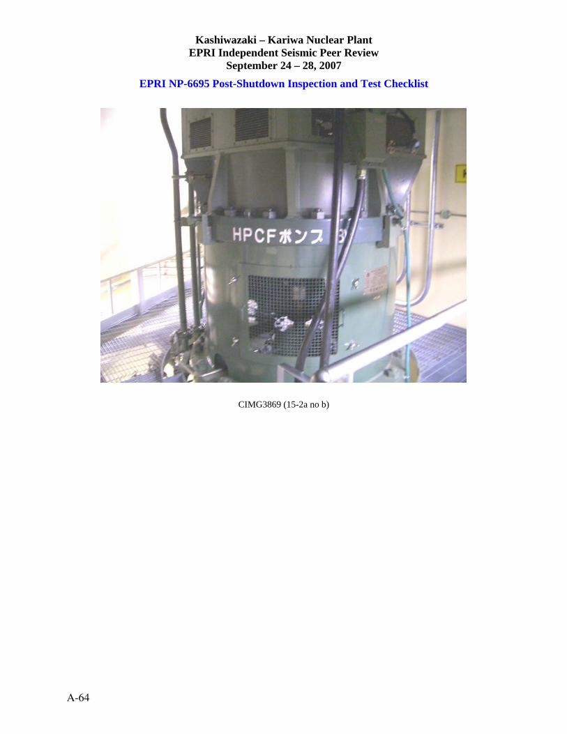
Kashiwazaki – Kariwa Nuclear Plant EPRI Independent Seismic Peer Review
September 24 – 28, 2007
EPRI NP-6695 Post-Shutdown Inspection and Test Checklist
CIMG3869 (15-2a no b)
A-64

Kashiwazaki – Kariwa Nuclear Plant EPRI Independent Seismic Peer Review
September 24 – 28, 2007
EPRI NP-6695 Post-Shutdown Inspection and Test Checklist INSTRUMENT RACKS (16-1) Check box if acceptable: 1. Check equipment anchorage for damage; e.g., stretching or loosening
of anchor bolts or nuts; rocking or sliding of equipment. Comments: ________________________________________________
2. Check for distortion of rack structure.
Comments: ________________________________________________
3. Check for damage to attached conduit and ground straps. Comments: ________________________________________________
4. Check to see that instruments mounted to the rack are secure and undamaged.
Comments: ________________________________________________
5. Check for damage due to impact or earthquake induced flooding or spraying.
Comments: ________________________________________________
6. Check local alarms, breakers and protective devices for actuation/trips.
Comments: N/A_____________________________________________
7. Reset any trips. Investigate any re-trips after reset.
Comments: N/A_____________________________________________
Walkdown Notes/Comments: General Instrument Racks in Unit 1 Reactor Building, Rugged instrument
___ rack with no damage visible__________________________________________________________
_____________________________________________________________________________________
Picture Numbers: CIMG3977 (16-1a) CIMG3978 (16-1b) ___________________________________ ___________________________________ Greg Hardy James Johnson ARES Corporation James J. Johnson and Associates
___________________________________ ___________________________________ William Schmidt Jerry Kernaghan W. Schmidt Consulting Electrical Power Research Institute
Date: 09 / 27 / 07
KK Plant Unit #: 1
Plant Elevation: _______ meters
A-65

Kashiwazaki – Kariwa Nuclear Plant EPRI Independent Seismic Peer Review
September 24 – 28, 2007
EPRI NP-6695 Post-Shutdown Inspection and Test Checklist
CIMG3977 (16-1a)
CIMG3978 (16-1b)
A-66

Kashiwazaki – Kariwa Nuclear Plant EPRI Independent Seismic Peer Review
September 24 – 28, 2007
EPRI NP-6695 Post-Shutdown Inspection and Test Checklist INSTRUMENT RACKS – FW Pump Instr. Rack Check box if acceptable: 1. Check equipment anchorage for damage; e.g., stretching or loosening
of anchor bolts or nuts; rocking or sliding of equipment. Comments: ________________________________________________
2. Check for distortion of rack structure.
Comments: ________________________________________________
3. Check for damage to attached conduit and ground straps. Comments: ________________________________________________
4. Check to see that instruments mounted to the rack are secure and undamaged.
Comments: ________________________________________________
5. Check for damage due to impact or earthquake induced flooding or spraying.
Comments: ________________________________________________
6. Check local alarms, breakers and protective devices for actuation/trips.
Comments: N/A_____________________________________________
7. Reset any trips. Investigate any re-trips after reset.
Comments: N/A_____________________________________________
Walkdown Notes/Comments: NVD, Undisturbed condition______________________________________
_____________________________________________________________________________________
_____________________________________________________________________________________
_____________________________________________________________________________________
Picture Numbers: CIMG3880 (16-2a) CIMG3878 (16-2b) ___________________________________ ___________________________________ Greg Hardy James Johnson ARES Corporation James J. Johnson and Associates
___________________________________ ___________________________________ William Schmidt Jerry Kernaghan W. Schmidt Consulting Electrical Power Research Institute
Date: 09 / 25 / 07
KK Plant Unit #: 7
Plant Elevation: _______ meters
A-67

Kashiwazaki – Kariwa Nuclear Plant EPRI Independent Seismic Peer Review
September 24 – 28, 2007
EPRI NP-6695 Post-Shutdown Inspection and Test Checklist
CIMG3880 (16-2a)
CIMG3878 (16-2b)
A-68
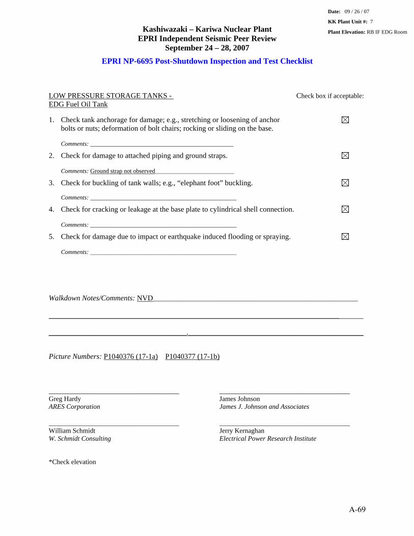
Kashiwazaki – Kariwa Nuclear Plant EPRI Independent Seismic Peer Review
September 24 – 28, 2007
EPRI NP-6695 Post-Shutdown Inspection and Test Checklist LOW PRESSURE STORAGE TANKS - Check box if acceptable: EDG Fuel Oil Tank 1. Check tank anchorage for damage; e.g., stretching or loosening of anchor
bolts or nuts; deformation of bolt chairs; rocking or sliding on the base.
Comments: _______________________________________________
2. Check for damage to attached piping and ground straps.
Comments: Ground strap not observed__________________________
3. Check for buckling of tank walls; e.g., “elephant foot” buckling.
Comments: ________________________________________________
4. Check for cracking or leakage at the base plate to cylindrical shell connection. Comments: ________________________________________________
5. Check for damage due to impact or earthquake induced flooding or spraying.
Comments: ________________________________________________
Walkdown Notes/Comments: NVD_______________________________________________________ . ______________________________________________________________________________ . _____________________________________._______________________________________________
Picture Numbers: P1040376 (17-1a) P1040377 (17-1b) ___________________________________ ___________________________________ Greg Hardy James Johnson ARES Corporation James J. Johnson and Associates
___________________________________ ___________________________________ William Schmidt Jerry Kernaghan W. Schmidt Consulting Electrical Power Research Institute *Check elevation
Date: 09 / 26 / 07
KK Plant Unit #: 7
Plant Elevation: RB IF EDG Room
A-69

Kashiwazaki – Kariwa Nuclear Plant EPRI Independent Seismic Peer Review
September 24 – 28, 2007
EPRI NP-6695 Post-Shutdown Inspection and Test Checklist
P1040376 (17-1a)
P1040377 (17-1b)
A-70

Kashiwazaki – Kariwa Nuclear Plant EPRI Independent Seismic Peer Review
September 24 – 28, 2007
EPRI NP-6695 Post-Shutdown Inspection and Test Checklist LOW PRESSURE STORAGE TANKS Check box if acceptable: Demin. water and caustic storage tanks. Non safety-related (NSR) 1. Check tank anchorage for damage; e.g., stretching or loosening of anchor
bolts or nuts; deformation of bolt chairs; rocking or sliding on the base.
Comments: Significant failures of anchor bolts and pedestals_________
2. Check for damage to attached piping and ground straps.
Comments: N/A_____________________________________________
3. Check for buckling of tank walls; e.g., “elephant foot” buckling.
Comments: ________________________________________________
4. Check for cracking or leakage at the base plate to cylindrical shell connection. Comments: None observed____________________________________
5. Check for damage due to impact or earthquake induced flooding or spraying.
Comments: Damage apparent__________________________________
Walkdown Notes/Comments: General failures of several tank anchorages – pulled out anchors, severely . cracked pedestals. Caustic tank tipped over partially and was restrained by fire protector piping. . Ultimately lifted off pedestals and set on floor._______________________________________________
_____________________________________________________________________________________
Picture Numbers: DSCF0006 (17-2a) DSCF0010 (17-2b)
___________________________________ ___________________________________ Greg Hardy James Johnson ARES Corporation James J. Johnson and Associates
___________________________________ ___________________________________ William Schmidt Jerry Kernaghan W. Schmidt Consulting Electrical Power Research Institute *Note 1: Toured non safety-related water treatment building, grade level
Date: 09 / 25 / 07
KK Plant Unit #: Note 1
Plant Elevation: Grade meters Water Treatment Bldg
A-71

Kashiwazaki – Kariwa Nuclear Plant EPRI Independent Seismic Peer Review
September 24 – 28, 2007
EPRI NP-6695 Post-Shutdown Inspection and Test Checklist
DSCF0006 (17-2a)
DSCF0010 (17-2b)
A-72

Kashiwazaki – Kariwa Nuclear Plant EPRI Independent Seismic Peer Review
September 24 – 28, 2007
EPRI NP-6695 Post-Shutdown Inspection and Test Checklist LOW PRESSURE STORAGE TANKS Check box if acceptable: Outdoor Filtered city water NSR LP storage tanks 1. Check tank anchorage for damage; e.g., stretching or loosening of anchor
bolts or nuts; deformation of bolt chairs; rocking or sliding on the base.
Comments: Multiple failures.__________________________________
2. Check for damage to attached piping and ground straps.
Comments: Distortion, leakage of some flanged joints______________
3. Check for buckling of tank walls; e.g., “elephant foot” buckling.
Comments: “Elephant foot” and diamond buckling on some tanks in upper 1/3
4. Check for cracking or leakage at the base plate to cylindrical shell connection. Comments: Separation of tank from ground foundation at all tanks. Shell buckling, anchor bolt failure, chair buckling, shell cracking/tearing and leakage on 1008KL city water tank
5. Check for damage due to impact or earthquake induced flooding or spraying.
Comments: Significant impact/damage___________________________
Walkdown Notes/Comments: Dimensional and fluid inventory data provided to EPRI for further analysis. . ______________________________________________________________________________ . _____________________________________._______________________________________________
_____________________________________________________________________________________
Picture Numbers: IMG_1214 (17-3a) IMG_1210 (17-3b)
___________________________________ ___________________________________ Greg Hardy James Johnson ARES Corporation James J. Johnson and Associates
___________________________________ ___________________________________ William Schmidt Jerry Kernaghan W. Schmidt Consulting Electrical Power Research Institute *Note 1: Inspected NSR LP water storage tanks on grade in yard area.
Date: 09 / 25 / 07
KK Plant Unit #: Note 1
Plant Elevation: _____ meters
A-73

Kashiwazaki – Kariwa Nuclear Plant EPRI Independent Seismic Peer Review
September 24 – 28, 2007
EPRI NP-6695 Post-Shutdown Inspection and Test Checklist
IMG_1214 (17-3a)
IMG_1210 (17-3b)
A-74
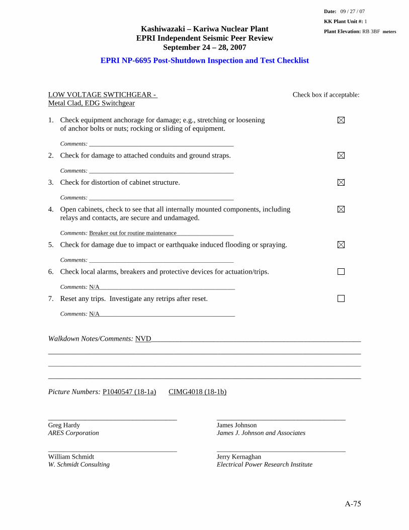
Kashiwazaki – Kariwa Nuclear Plant EPRI Independent Seismic Peer Review
September 24 – 28, 2007
EPRI NP-6695 Post-Shutdown Inspection and Test Checklist LOW VOLTAGE SWTICHGEAR - Check box if acceptable: Metal Clad, EDG Switchgear 1. Check equipment anchorage for damage; e.g., stretching or loosening
of anchor bolts or nuts; rocking or sliding of equipment.
Comments: ________________________________________________
2. Check for damage to attached conduits and ground straps.
Comments: ________________________________________________
3. Check for distortion of cabinet structure. Comments: ________________________________________________
4. Open cabinets, check to see that all internally mounted components, including relays and contacts, are secure and undamaged. Comments: Breaker out for routine maintenance___________________
5. Check for damage due to impact or earthquake induced flooding or spraying.
Comments: ________________________________________________
6. Check local alarms, breakers and protective devices for actuation/trips.
Comments: N/A_____________________________________________
7. Reset any trips. Investigate any retrips after reset.
Comments: N/A_____________________________________________ Walkdown Notes/Comments: NVD_________________________________________________________
_____________________________________________________________________________________
_____________________________________________________________________________________
_____________________________________________________________________________________
Picture Numbers: P1040547 (18-1a) CIMG4018 (18-1b) ___________________________________ ___________________________________ Greg Hardy James Johnson ARES Corporation James J. Johnson and Associates
___________________________________ ___________________________________ William Schmidt Jerry Kernaghan W. Schmidt Consulting Electrical Power Research Institute
Date: 09 / 27 / 07
KK Plant Unit #: 1
Plant Elevation: RB 3BF meters
A-75

Kashiwazaki – Kariwa Nuclear Plant EPRI Independent Seismic Peer Review
September 24 – 28, 2007
EPRI NP-6695 Post-Shutdown Inspection and Test Checklist
P1040547 (18-1a)
CIMG4018 (18-1b)
A-76

Kashiwazaki – Kariwa Nuclear Plant EPRI Independent Seismic Peer Review
September 24 – 28, 2007
EPRI NP-6695 Post-Shutdown Inspection and Test Checklist LOW VOLTAGE SWTICHGEAR - Check box if acceptable: Metal Clad, E.D. Generator Switch Gear 1. Check equipment anchorage for damage; e.g., stretching or loosening
of anchor bolts or nuts; rocking or sliding of equipment.
Comments: ________________________________________________
2. Check for damage to attached conduits and ground straps.
Comments: ________________________________________________
3. Check for distortion of cabinet structure. Comments: ________________________________________________
4. Open cabinets, check to see that all internally mounted components, including relays and contacts, are secure and undamaged. Comments: ________________________________________________
5. Check for damage due to impact or earthquake induced flooding or spraying.
Comments: ________________________________________________
6. Check local alarms, breakers and protective devices for actuation/trips.
Comments: N/A_____________________________________________
7. Reset any trips. Investigate any retrips after reset.
Comments: N/A_____________________________________________ Walkdown Notes/Comments: NVD_________________________________________________________
_____________________________________________________________________________________
_____________________________________________________________________________________
_____________________________________________________________________________________
Picture Numbers: CIMG3956 (18-2a) CIMG3954 (18-2b) ___________________________________ ___________________________________ Greg Hardy James Johnson ARES Corporation James J. Johnson and Associates
___________________________________ ___________________________________ William Schmidt Jerry Kernaghan W. Schmidt Consulting Electrical Power Research Institute
Date: 09 / 26 / 07
KK Plant Unit #: 7
Plant Elevation: BIF C Bldg meters
A-77

Kashiwazaki – Kariwa Nuclear Plant EPRI Independent Seismic Peer Review
September 24 – 28, 2007
EPRI NP-6695 Post-Shutdown Inspection and Test Checklist
CIMG3956 (18-2a)
CIMG3954 (18-2b)
A-78

Kashiwazaki – Kariwa Nuclear Plant EPRI Independent Seismic Peer Review
September 24 – 28, 2007
EPRI NP-6695 Post-Shutdown Inspection and Test Checklist MEDIUM VOLTAGE SWTICHGEAR – Check box if acceptable: EDG 6.9 KV Switchgear 1. Check equipment anchorage for damage; e.g., stretching or loosening
of anchor bolts or nuts; rocking or sliding of equipment.
Comments: ________________________________________________
2. Check for damage to attached conduit and ground straps.
Comments: ________________________________________________
3. Check for distortion of cabinet structure. Comments: ________________________________________________
4. Open cabinets, check to see that internally mounted components, including relays and contacts, are secure and undamaged. – by G. Hardy Comments: ________________________________________________
5. Check for damage due to impact or earthquake induced flooding or spraying.
Comments: ________________________________________________
6. Check local alarms, breakers and protective devices for actuation/trips.
Comments: N/A_____________________________________________
7. Reset any trips. Investigate any re-trips after reset.
Comments: N/A_____________________________________________ Walkdown Notes/Comments: _____________________________________________________________
_____________________________________________________________________________________
_____________________________________________________________________________________
_____________________________________________________________________________________
Picture Numbers: CIMG4007 (19-1a) CIMG4011 (19-1b) ___________________________________ ___________________________________ Greg Hardy James Johnson ARES Corporation James J. Johnson and Associates
___________________________________ ___________________________________ William Schmidt Jerry Kernaghan W. Schmidt Consulting Electrical Power Research Institute
Date: 09 / 27 / 07
KK Plant Unit #: 1
Plant Elevation: RB-B3F meters
A-79

Kashiwazaki – Kariwa Nuclear Plant EPRI Independent Seismic Peer Review
September 24 – 28, 2007
EPRI NP-6695 Post-Shutdown Inspection and Test Checklist
CIMG4007 (19-1a)
CIMG4011 (19-1b)
A-80
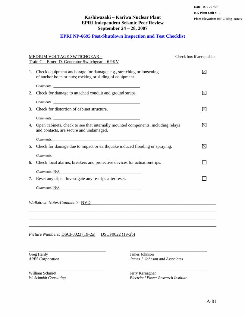
Kashiwazaki – Kariwa Nuclear Plant EPRI Independent Seismic Peer Review
September 24 – 28, 2007
EPRI NP-6695 Post-Shutdown Inspection and Test Checklist MEDIUM VOLTAGE SWTICHGEAR – Check box if acceptable: Train C – Emer. D. Generator Switchgear – 6.9KV 1. Check equipment anchorage for damage; e.g., stretching or loosening
of anchor bolts or nuts; rocking or sliding of equipment.
Comments: ________________________________________________
2. Check for damage to attached conduit and ground straps.
Comments: ________________________________________________
3. Check for distortion of cabinet structure. Comments: ________________________________________________
4. Open cabinets, check to see that internally mounted components, including relays and contacts, are secure and undamaged. Comments: ________________________________________________
5. Check for damage due to impact or earthquake induced flooding or spraying.
Comments: ________________________________________________
6. Check local alarms, breakers and protective devices for actuation/trips.
Comments: N/A_____________________________________________
7. Reset any trips. Investigate any re-trips after reset.
Comments: N/A_____________________________________________ Walkdown Notes/Comments: NVD_________________________________________________________
_____________________________________________________________________________________
_____________________________________________________________________________________
_____________________________________________________________________________________
Picture Numbers: DSCF0023 (19-2a) DSCF0022 (19-2b) ___________________________________ ___________________________________ Greg Hardy James Johnson ARES Corporation James J. Johnson and Associates
___________________________________ ___________________________________ William Schmidt Jerry Kernaghan W. Schmidt Consulting Electrical Power Research Institute
Date: 09 / 26 / 07
KK Plant Unit #: 7
Plant Elevation: BIF C Bldg meters
A-81
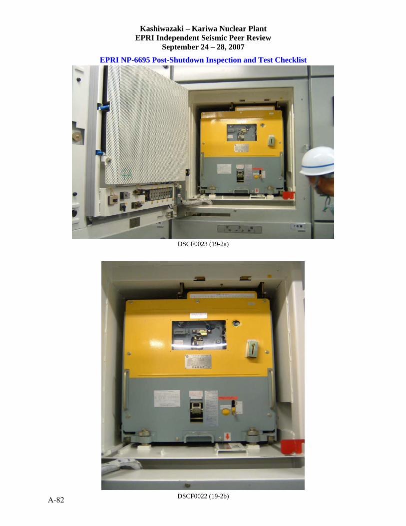
Kashiwazaki – Kariwa Nuclear Plant EPRI Independent Seismic Peer Review
September 24 – 28, 2007
EPRI NP-6695 Post-Shutdown Inspection and Test Checklist
DSCF0023 (19-2a)
DSCF0022 (19-2b) A-82

Kashiwazaki – Kariwa Nuclear Plant EPRI Independent Seismic Peer Review
September 24 – 28, 2007
EPRI NP-6695 Post-Shutdown Inspection and Test Checklist MOTOR CONTROL CENTERS – EDG MCC IC-1-5 Check box if acceptable: 1. Check equipment anchorage for damage; e.g., stretching or loosening
of anchor bolts or nuts; rocking or sliding of equipment.
Comments: Base anchorage only_______________________________
2. Check for damage to attached conduits and ground straps. Comments: ________________________________________________
3. Check for distortion of cabinet structure. Comments: ________________________________________________
4. Open cabinet, check to see that internally mounted components, including relays and breakers, are secure and undamaged. Comments: ________________________________________________
5. Check for damage due to impact or earthquake induced flooding or spraying.
Comments: ________________________________________________
6. Check controls, breakers and protective devices for actuations/trips.
Comments: N/A_____________________________________________ Walkdown Notes/Comments: Cabinets bolted together. Inspection by GIT__________________________
_____________________________________________________________________________________
_____________________________________________________________________________________
_____________________________________________________________________________________
Picture Numbers: CIMG4020 (20-1a) CIMG4019 (20-1b) ___________________________________ ___________________________________ Greg Hardy James Johnson ARES Corporation James J. Johnson and Associates
___________________________________ ___________________________________ William Schmidt Jerry Kernaghan W. Schmidt Consulting Electrical Power Research Institute *Please check name/ID. Near HP FW Heater Room IF TB
Date: 09 / 27 / 07
KK Plant Unit #: U1
Plant Elevation: RB meters
A-83

Kashiwazaki – Kariwa Nuclear Plant EPRI Independent Seismic Peer Review
September 24 – 28, 2007
EPRI NP-6695 Post-Shutdown Inspection and Test Checklist
CIMG4020 (20-1a)
CIMG4019 (20-1b)
A-84
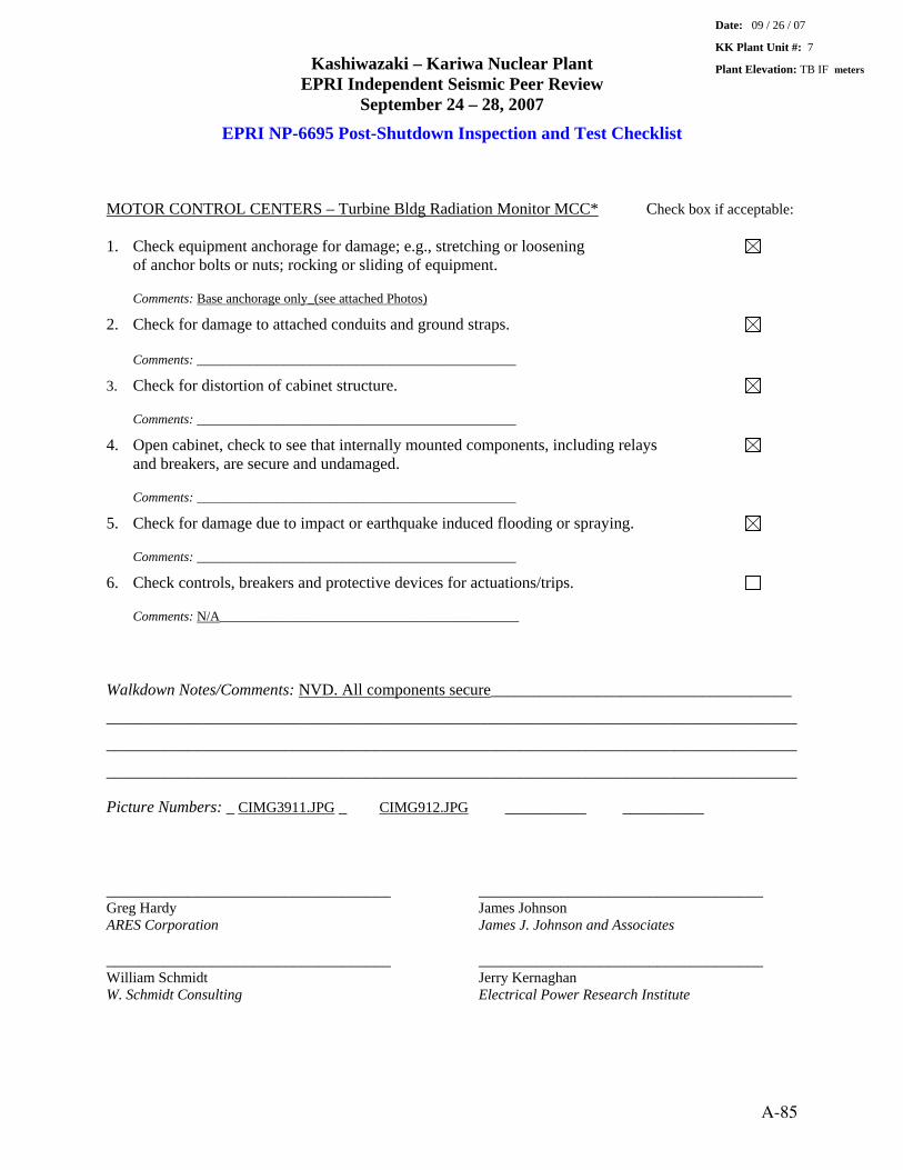
Kashiwazaki – Kariwa Nuclear Plant EPRI Independent Seismic Peer Review
September 24 – 28, 2007
EPRI NP-6695 Post-Shutdown Inspection and Test Checklist MOTOR CONTROL CENTERS – Turbine Bldg Radiation Monitor MCC* Check box if acceptable: 1. Check equipment anchorage for damage; e.g., stretching or loosening
of anchor bolts or nuts; rocking or sliding of equipment.
Comments: Base anchorage only_(see attached Photos)
2. Check for damage to attached conduits and ground straps. Comments: ________________________________________________
3. Check for distortion of cabinet structure. Comments: ________________________________________________
4. Open cabinet, check to see that internally mounted components, including relays and breakers, are secure and undamaged. Comments: ________________________________________________
5. Check for damage due to impact or earthquake induced flooding or spraying.
Comments: ________________________________________________
6. Check controls, breakers and protective devices for actuations/trips.
Comments: N/A_____________________________________________ Walkdown Notes/Comments: NVD. All components secure_____________________________________
_____________________________________________________________________________________
_____________________________________________________________________________________
_____________________________________________________________________________________
Picture Numbers: _ CIMG3911.JPG _ CIMG912.JPG __________ __________
___________________________________ ___________________________________ Greg Hardy James Johnson ARES Corporation James J. Johnson and Associates
___________________________________ ___________________________________ William Schmidt Jerry Kernaghan W. Schmidt Consulting Electrical Power Research Institute
Date: 09 / 26 / 07
KK Plant Unit #: 7
Plant Elevation: TB IF meters
A-85

Kashiwazaki – Kariwa Nuclear Plant EPRI Independent Seismic Peer Review
September 24 – 28, 2007
EPRI NP-6695 Post-Shutdown Inspection and Test Checklist
CIMG3911.JPG
CIMG912.JPG
A-86

Kashiwazaki – Kariwa Nuclear Plant EPRI Independent Seismic Peer Review
September 24 – 28, 2007
EPRI NP-6695 Post-Shutdown Inspection and Test Checklist Unit 1 PLR MG Sets (1 of 2) MOTOR GENERATORS Check box if acceptable: 1. Check equipment anchorage/isolation mounts for damage; e.g., stretching X
or loosening of anchor bolts or nuts; rocking or sliding of equipment.
Comments: No visible damage.
2. Check for noise and/or vibration caused by misalignment between motor and generator shaft, especially if they are not mounted to a common base. Comments: Not operating.
3. Check for damage to attached conduits and ground straps. X Comments: ________________________________________________
4. Check for damage due to impact or earthquake induced flooding or spraying X Comments: ________________________________________________
5. Check local alarms, breakers and protective devices for actuation/trips. X
Comments: ________________________________________________ Walkdown Notes/Comments: Operability unknown as of 09/27/2007.
Picture Numbers: IMG0341 CIMG4039
___________________________________ ___________________________________ Greg Hardy James Johnson ARES Corporation James J. Johnson and Associates
___________________________________ ___________________________________ William Schmidt Jerry Kernaghan W. Schmidt Consulting Electrical Power Research Institute
Date: 09 / 27 / 2007
KK Plant Unit #: 1
Plant Elevation: Combination Building 1F _ meters
A-87

Kashiwazaki – Kariwa Nuclear Plant EPRI Independent Seismic Peer Review
September 24 – 28, 2007
EPRI NP-6695 Post-Shutdown Inspection and Test Checklist
IMG0341
CIMG4039
A-88

Kashiwazaki – Kariwa Nuclear Plant EPRI Independent Seismic Peer Review
September 24 – 28, 2007
EPRI NP-6695 Post-Shutdown Inspection and Test Checklist Unit 1 PLR MG Sets (2 of 2) MOTOR GENERATORS Check box if acceptable: 1. Check equipment anchorage/isolation mounts for damage; e.g., stretching X
or loosening of anchor bolts or nuts; rocking or sliding of equipment.
Comments: No visible damage.
2. Check for noise and/or vibration caused by misalignment between motor and generator shaft, especially if they are not mounted to a common base. Comments: Not operating.
3. Check for damage to attached conduits and ground straps. X Comments: ________________________________________________
4. Check for damage due to impact or earthquake induced flooding or spraying X Comments: ________________________________________________
5. Check local alarms, breakers and protective devices for actuation/trips. X
Comments: ________________________________________________ Walkdown Notes/Comments: Operability unknown as of 09/27/2007.
Picture Numbers: Refer to CIMG4039 IMG0341 of PLR MG Sets (1 of 2) Added Photos here applicable to both. CIMG4038 IMG0342
___________________________________ ___________________________________ Greg Hardy James Johnson ARES Corporation James J. Johnson and Associates
___________________________________ ___________________________________ William Schmidt Jerry Kernaghan W. Schmidt Consulting Electrical Power Research Institute
Date: 09 / 27 / 2007
KK Plant Unit #: 1
Plant Elevation: Combination Building 1F _ meters
A-89

Kashiwazaki – Kariwa Nuclear Plant EPRI Independent Seismic Peer Review
September 24 – 28, 2007
EPRI NP-6695 Post-Shutdown Inspection and Test Checklist
IMG0342
CIMG4038
A-90

Kashiwazaki – Kariwa Nuclear Plant EPRI Independent Seismic Peer Review
September 24 – 28, 2007
EPRI NP-6695 Post-Shutdown Inspection and Test Checklist SLC Tank and Piping – Unit 1 RB B2FL PIPING Check box if acceptable: 1. Check for snubber damage; e.g., snubbers pulled loose from foundation X
bolts, evidence of excessive travel, jam up of inertia mechanism/leakage of hydraulic fluid and bent piston rods.
Comments: No snubbers.
2. Check for damage at rigid supports; e.g., deformation of support structure, X deformation of pipe due to impact with support structure. Comments: No evidence of impact adjoining structure components.
3. Check for damage or leakage of pipe at rigid connections; e.g., anchor points X with other equipment and structures. Comments: No visible evidence of damage or leaks.
4. Check for damage or leakage of piping and branch lines. X Comments: No visible evidence of damage or leaks.
5. Check for damage to pipe at building joints and interfaces between buildings. X
Comments: Does not cross building joints.
6. Check for damage due to impact or earthquake induced flooding or spraying. X
Comments: None. Walkdown Notes/Comments: SLC piping – Stainless Steel; supported by structural steel supports (channels and box sections); attached to supports by U clamps; piping run in very close proximity to structural steel column – no indication of impact between column and piping.
Picture Numbers: P1040475 P1040477
___________________________________ ___________________________________ Greg Hardy James Johnson ARES Corporation James J. Johnson and Associates
___________________________________ ___________________________________ William Schmidt Jerry Kernaghan W. Schmidt Consulting Electrical Power Research Institute
Date: 09 /27 / 2007
KK Plant Unit #: 1
Plant Elevation: RB B2FL meters
A-91

Kashiwazaki – Kariwa Nuclear Plant EPRI Independent Seismic Peer Review
September 24 – 28, 2007
EPRI NP-6695 Post-Shutdown Inspection and Test Checklist
P1040475
P1040477
A-92

Kashiwazaki – Kariwa Nuclear Plant EPRI Independent Seismic Peer Review
September 24 – 28, 2007
EPRI NP-6695 Post-Shutdown Inspection and Test Checklist General Piping supported by Reinforced Concrete Wall PIPING Check box if acceptable: 1. Check for snubber damage; e.g., snubbers pulled loose from foundation X
bolts, evidence of excessive travel, jam up of inertia mechanism/leakage of hydraulic fluid and bent piston rods.
Comments: No snubbers.
2. Check for damage at rigid supports; e.g., deformation of support structure, X deformation of pipe due to impact with support structure. Comments: No visible damage.
3. Check for damage or leakage of pipe at rigid connections; e.g., anchor points X with other equipment and structures. Comments: No visible damage.
4. Check for damage or leakage of piping and branch lines. Comments: None.
5. Check for damage to pipe at building joints and interfaces between buildings. X
Comments: Piping does not cross building joints.
6. Check for damage due to impact or earthquake induced flooding or spraying. X
Comments: None. Walkdown Notes/Comments: Typical piping configurations and support conditions.
Picture Numbers: P1040486 P1040487
___________________________________ ___________________________________ Greg Hardy James Johnson ARES Corporation James J. Johnson and Associates
___________________________________ ___________________________________ William Schmidt Jerry Kernaghan W. Schmidt Consulting Electrical Power Research Institute
Date: 09 / 27 / 2007
KK Plant Unit #: 1
Plant Elevation: RB 2FL _ meters
A-93

Kashiwazaki – Kariwa Nuclear Plant EPRI Independent Seismic Peer Review
September 24 – 28, 2007
EPRI NP-6695 Post-Shutdown Inspection and Test Checklist
P1040486
P1040487
A-94

Kashiwazaki – Kariwa Nuclear Plant EPRI Independent Seismic Peer Review
September 24 – 28, 2007
EPRI NP-6695 Post-Shutdown Inspection and Test Checklist Unit 1 CRD HCU System PRIMARY COOLANT SYSTEM Check box if acceptable: 1. Check for reactor coolant leakage at flanged joints; e.g., CRD mechanisms.
Comments: No visible leakage during the visual inspections.
2. Check for condition of supports and snubbers for large components; e.g., main coolant pumps, steam generators, pressurizer. Comments: Not applicable.
3. Check condition of CRDM support structure (PWRs only). Comments:. Not applicable.
Walkdown Notes/Comments: Unit 1 was not operating at the time of the earthquake; no operability checks performed as of 09/27/07. CRD HCUs well supported (see Photos). No visible damage
Picture Numbers: P1040468 IMG0300
___________________________________ ___________________________________ Greg Hardy James Johnson ARES Corporation James J. Johnson and Associates
___________________________________ ___________________________________ William Schmidt Jerry Kernaghan W. Schmidt Consulting Electrical Power Research Institute
Date: 09 / 27 / 2007
KK Plant Unit #: 1
Plant Elevation: RB B3F __ meters
A-95

Kashiwazaki – Kariwa Nuclear Plant EPRI Independent Seismic Peer Review
September 24 – 28, 2007
EPRI NP-6695 Post-Shutdown Inspection and Test Checklist
P1040468
IMG0300
A-96

Kashiwazaki – Kariwa Nuclear Plant EPRI Independent Seismic Peer Review
September 24 – 28, 2007
EPRI NP-6695 Post-Shutdown Inspection and Test Checklist Unit 7 CRD HCU System PRIMARY COOLANT SYSTEM Check box if acceptable: 1. Check for reactor coolant leakage at flanged joints; e.g., CRD mechanisms.
Comments: No leakage observed during the visual inspections
2. Check for condition of supports and snubbers for large components; e.g., main coolant pumps, steam generators, pressurizer. Comments: Not applicable.
3. Check condition of CRDM support structure (PWRs only). Comments:. Not applicable.
Walkdown Notes/Comments: Unit 7 was operating at the time of the earthquake and shutdown successfully due to the seismic scram. Conclusion is that the CRDs and HCUs operated during the earthquake. October 11, TEPCO announced that one of the 205 control rods for Unit 7 was stuck in the core and could not be removed after removing the fuel assemblies surrounding it. Although this anomaly has been reported, the evidence is that the shutdown of Unit 7 occurred uneventfully. CRD HCUs very well supported (see Photos). No visible damage. Operated successfully during the NCOE
Picture Numbers: CIMG3894 CIMG3892Rot
___________________________________ ___________________________________ Greg Hardy James Johnson ARES Corporation James J. Johnson and Associates
___________________________________ ___________________________________ William Schmidt Jerry Kernaghan W. Schmidt Consulting Electrical Power Research Institute
Date: 09 /26 / 2007
KK Plant Unit #: 7
Plant Elevation: RB B3F _ meters
A-97

Kashiwazaki – Kariwa Nuclear Plant EPRI Independent Seismic Peer Review
September 24 – 28, 2007
EPRI NP-6695 Post-Shutdown Inspection and Test Checklist
CIMG3894
CIMG3892Rot
A-98

Kashiwazaki – Kariwa Nuclear Plant EPRI Independent Seismic Peer Review
September 24 – 28, 2007
EPRI NP-6695 Post-Shutdown Inspection and Test Checklist Reinforced Concrete Wall between Unit 6 and 7 Turbine Buildings – Operating Floor 2F REINFORCED CONCRETE STRUCTURES & MASONRY WALLS Check box if acceptable: 1. Check for new open (>0.06 inches) cracks, spalling of concrete. [Note:
Minor cracks, even if caused by the earthquake, are not considered significant unless they are large enough to result in yielding of rebar.]
Comments: See discussion below; hairline diagonal cracks of unknown origin observed.
2. Check for evidence of ground settlement. X
Comments: ________________________________________________
3. Check for evidence of differential horizontal and vertical movement between adjacent and/or interconnecting buildings/structures. Comments: Only relative motion reported on Turbine Building Operating Floor/Turbine Pedestal interface.
Walkdown Notes/Comments: Observed diagonal hairline cracks in east wall near Unit 7 interface and north wall between Unit 6 and 7; not inspected by Structure Group as of 09/27/2007 (Meeting with Structure Group to understand crack monitoring program).
_____________________________________________________________________________________
Picture Numbers: DSCF0010 DSCF0011
___________________________________ ___________________________________ Greg Hardy James Johnson ARES Corporation James J. Johnson and Associates
___________________________________ ___________________________________ William Schmidt Jerry Kernaghan W. Schmidt Consulting Electrical Power Research Institute
Date: 09 / 25 / 2007
KK Plant Unit #: 7
Plant Elevation: TB 2F __ meters
A-99

Kashiwazaki – Kariwa Nuclear Plant EPRI Independent Seismic Peer Review
September 24 – 28, 2007
EPRI NP-6695 Post-Shutdown Inspection and Test Checklist
DSCF0010 – Diagonal Cracks East Wall
DSCF0011 –Diagonal Cracks – North Wall
A-100

Kashiwazaki – Kariwa Nuclear Plant EPRI Independent Seismic Peer Review
September 24 – 28, 2007
EPRI NP-6695 Post-Shutdown Inspection and Test Checklist Unit 7 Turbine Building Operating Floor – Pedestal – Pounding REINFORCED CONCRETE STRUCTURES & MASONRY WALLS Check box if acceptable: 1. Check for new open (>0.06 inches) cracks, spalling of concrete. [Note:
Minor cracks, even if caused by the earthquake, are not considered significant unless they are large enough to result in yielding of rebar.]
Comments: See discussion below and Photos.
2. Check for evidence of ground settlement. X
Comments: Not a cause.
3. Check for evidence of differential horizontal and vertical movement between adjacent and/or interconnecting buildings/structures. Comments: Local crushing of concrete at turbine operating floor and turbine pedestal interface.
Walkdown Notes/Comments: Evidence of pounding or impact between turbine building operating floor and turbine pedestal along east side of operating floor; some local crushing of concrete at 90 deg. angles and other locations; not inspected by Structure Group as of 09/27/2007 (Meeting with Structure Group to understand crack monitoring program).
Picture Numbers: DSCF0020 DSCF0016 ___________________________________ ___________________________________ Greg Hardy James Johnson ARES Corporation James J. Johnson and Associates
___________________________________ ___________________________________ William Schmidt Jerry Kernaghan W. Schmidt Consulting Electrical Power Research Institute
Date: 09 / 25 / 2007
KK Plant Unit #: 7
Plant Elevation: TB 2F
A-101

Kashiwazaki – Kariwa Nuclear Plant EPRI Independent Seismic Peer Review
September 24 – 28, 2007
EPRI NP-6695 Post-Shutdown Inspection and Test Checklist
DSCF0020
DSCF0016
A-102

Kashiwazaki – Kariwa Nuclear Plant EPRI Independent Seismic Peer Review
September 24 – 28, 2007
EPRI NP-6695 Post-Shutdown Inspection and Test Checklist Temperature Sensor – Balcony of the HCU Compartment SENSORS Check box if acceptable: 1. Check for damage to attached conduit/tubing and ground straps. X
Comments: None. Flexible conduit. .
2. Check for damage due to impact or earthquake induced flooding or spraying. X
Comments: None. Supported on wall - no sign of impact.
3. Verify sensor operation with readout check at local/control room indicators. Comments: Not verified – not tested as of 09/26/2007
Walkdown Notes/Comments: ____________________________________________________________
_____________________________________________________________________________________
_____________________________________________________________________________________
_____________________________________________________________________________________
Picture Numbers: CIMG3900Rot CIMG3901 ___________________________________ ___________________________________ Greg Hardy James Johnson ARES Corporation James J. Johnson and Associates
___________________________________ ___________________________________ William Schmidt Jerry Kernaghan W. Schmidt Consulting Electrical Power Research Institute
Date: 09 / 26 / 2007
KK Plant Unit #: 7
Plant Elevation: RB B3F HCU Balcony meters
A-103
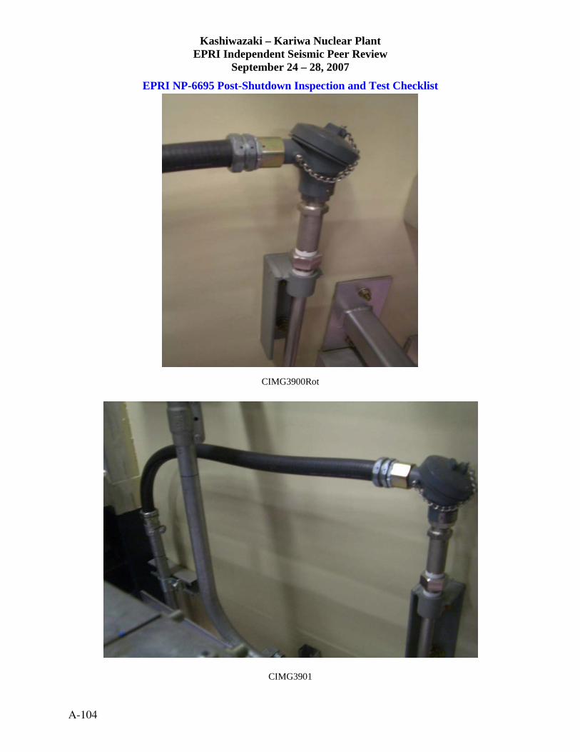
Kashiwazaki – Kariwa Nuclear Plant EPRI Independent Seismic Peer Review
September 24 – 28, 2007
EPRI NP-6695 Post-Shutdown Inspection and Test Checklist
CIMG3900Rot
CIMG3901
A-104

Kashiwazaki – Kariwa Nuclear Plant EPRI Independent Seismic Peer Review
September 24 – 28, 2007
EPRI NP-6695 Post-Shutdown Inspection and Test Checklist RTD – RHR HX Compartment SENSORS Check box if acceptable: 1. Check for damage to attached conduit/tubing and ground straps. X
Comments: No visible damage.
2. Check for damage due to impact or earthquake induced flooding or spraying. X
Comments: No visible damage.
3. Verify sensor operation with readout check at local/control room indicators. Comments: Not verified – not tested as of 09/26/2007.
Walkdown Notes/Comments: _____________________________________________________________
_____________________________________________________________________________________
_____________________________________________________________________________________
_____________________________________________________________________________________
Picture Numbers: CIMG3920 CIMG3921Rot ___________________________________ ___________________________________ Greg Hardy James Johnson ARES Corporation James J. Johnson and Associates
___________________________________ ___________________________________ William Schmidt Jerry Kernaghan W. Schmidt Consulting Electrical Power Research Institute
Date: 09 / 26 / 2007
KK Plant Unit #: 7
Plant Elevation: B1F_ meters
A-105
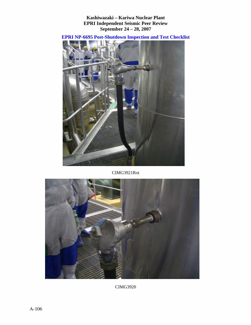
Kashiwazaki – Kariwa Nuclear Plant EPRI Independent Seismic Peer Review
September 24 – 28, 2007
EPRI NP-6695 Post-Shutdown Inspection and Test Checklist
CIMG3921Rot
CIMG3920
A-106

Kashiwazaki – Kariwa Nuclear Plant EPRI Independent Seismic Peer Review
September 24 – 28, 2007
EPRI NP-6695 Post-Shutdown Inspection and Test Checklist Unit 1 Emergency MCC Room B STATIC INVERTERS & BATTERY CHARGERS Check box if acceptable: 1. Check equipment anchorage for damage; e.g., stretching or loosening X
of anchor bolts or nuts; rocking or sliding of equipment.
Comments: Could not open – energized/operating; top support conduit and box steel frame – assume no damage due to operating
2. Check for damage to attached conduit and ground straps. X
Comments: Hard conduit to flex – no visible damage.
3. Check for distortion of cabinet structure. X Comments: No visible damage.
4. Open cabinet, check to see that internally mounted components are secure and X undamaged. Comments: Not accessible – energized and operating. Assume no damage.
5. Check for damage due to impact or earthquake induced flooding or spraying. X
Comments: No visible damage.
6. Check local alarms, breakers and protective devices for actuation/trips. X
Comments: ________________________________________________ Walkdown Notes/Comments: _____________________________________________________________
_____________________________________________________________________________________
_____________________________________________________________________________________
Picture Numbers: P1040521 P1040522
___________________________________ ___________________________________ Greg Hardy James Johnson ARES Corporation James J. Johnson and Associates
___________________________________ ___________________________________ William Schmidt Jerry Kernaghan W. Schmidt Consulting Electrical Power Research Institute
Date: _____ / _____ / _____
KK Plant Unit #: 1
Plant Elevation: C/B B1F __ meters
A-107

Kashiwazaki – Kariwa Nuclear Plant EPRI Independent Seismic Peer Review
September 24 – 28, 2007
EPRI NP-6695 Post-Shutdown Inspection and Test Checklist
P1040521
P1040522
A-108

Kashiwazaki – Kariwa Nuclear Plant EPRI Independent Seismic Peer Review
September 24 – 28, 2007
EPRI NP-6695 Post-Shutdown Inspection and Test Checklist Unit 7 Static Inverters/Battery Charger STATIC INVERTERS & BATTERY CHARGERS Check box if acceptable: 1. Check equipment anchorage for damage; e.g., stretching or loosening X
of anchor bolts or nuts; rocking or sliding of equipment.
Comments: Front row anchorage – standard detail.
2. Check for damage to attached conduit and ground straps. X
Comments: Ground straps to floor – no visible damage; conduit and cable tray from top – no visible damage.
3. Check for distortion of cabinet structure. X Comments: Internal cross-bracing – no visible damage.
4. Open cabinet, check to see that internally mounted components are secure and X undamaged. Comments: ________________________________________________
5. Check for damage due to impact or earthquake induced flooding or spraying. X
Comments: ________________________________________________
6. Check local alarms, breakers and protective devices for actuation/trips. X
Comments: ________________________________________________ Walkdown Notes/Comments: _____________________________________________________________
_____________________________________________________________________________________
_____________________________________________________________________________________
_____________________________________________________________________________________
Picture Numbers: CIMG3947 CIMG3954
___________________________________ ___________________________________ Greg Hardy James Johnson ARES Corporation James J. Johnson and Associates
___________________________________ ___________________________________ William Schmidt Jerry Kernaghan W. Schmidt Consulting Electrical Power Research Institute
Date: 09 / 26 / 2007
KK Plant Unit #: 7
Plant Elevation: B1F __ meters
A-109

Kashiwazaki – Kariwa Nuclear Plant EPRI Independent Seismic Peer Review
September 24 – 28, 2007
EPRI NP-6695 Post-Shutdown Inspection and Test Checklist
CIMG3947
CIMG3954
A-110

Kashiwazaki – Kariwa Nuclear Plant EPRI Independent Seismic Peer Review
September 24 – 28, 2007
EPRI NP-6695 Post-Shutdown Inspection and Test Checklist Cooling Water Pump House STEEL FRAMED STRUCTURES Check box if acceptable: 1. Check for damage at bolted or welded connections. X
Comments: No apparent visible damage.
2. Check for damage to anchorage; e.g., stretching or loosening of anchor bolts X or nuts; rocking or sliding of base plates on concrete. Comments: No apparent visible damage.
3. Check for distortion or buckling of braces and other compression members. X
Comments: See discussion below. No apparent visible damage to cross-bracing. Walkdown Notes/Comments: Class C building that experienced significant soil-related foundation damage and stub wall (reinforced concrete) damage; CWP has three separate foundations (one portion on piles, one portion underlain by reinforced concrete intake structure, and one portion supported on grade); specific structural steel damage appeared to be minimal as contrasted with the Unit 2 CWP with structural damage including cross bracing buckling – in neither case did the building collapse.
Picture Numbers: P1040345 P1040334
___________________________________ ___________________________________ Greg Hardy James Johnson ARES Corporation James J. Johnson and Associates
___________________________________ ___________________________________ William Schmidt Jerry Kernaghan W. Schmidt Consulting Electrical Power Research Institute
Date: 09 / 27 / 2007
KK Plant Unit #: 1
Plant Elevation: _______ meters
A-111

Kashiwazaki – Kariwa Nuclear Plant EPRI Independent Seismic Peer Review
September 24 – 28, 2007
EPRI NP-6695 Post-Shutdown Inspection and Test Checklist
P1040345
P1040334
A-112

Kashiwazaki – Kariwa Nuclear Plant EPRI Independent Seismic Peer Review
September 24 – 28, 2007
EPRI NP-6695 Post-Shutdown Inspection and Test Checklist Structural Steel Frame – Roof of Turbine Building, including Crane Rail STEEL FRAMED STRUCTURES Check box if acceptable: 1. Check for damage at bolted or welded connections. X
Comments: No visible or reported damage.
2. Check for damage to anchorage; e.g., stretching or loosening of anchor bolts X or nuts; rocking or sliding of base plates on concrete. Comments: No visible or reported damage.
3. Check for distortion or buckling of braces and other compression members. X
Comments: None visible. Walkdown Notes/Comments: _____________________________________________________________
_____________________________________________________________________________________
_____________________________________________________________________________________
_____________________________________________________________________________________
Picture Numbers: DSCF0022 DSCF0026
___________________________________ ___________________________________ Greg Hardy James Johnson ARES Corporation James J. Johnson and Associates
___________________________________ ___________________________________ William Schmidt Jerry Kernaghan W. Schmidt Consulting Electrical Power Research Institute
Date: 09 / 26 / 2007
KK Plant Unit #: 7
Plant Elevation: TB 2F __ meters
A-113

Kashiwazaki – Kariwa Nuclear Plant EPRI Independent Seismic Peer Review
September 24 – 28, 2007
EPRI NP-6695 Post-Shutdown Inspection and Test Checklist
DSCF0022
DSCF0026
A-114

Kashiwazaki – Kariwa Nuclear Plant EPRI Independent Seismic Peer Review
September 24 – 28, 2007
EPRI NP-6695 Post-Shutdown Inspection and Test Checklist Power Center Transformer 6.9KV to 480V TRANSFORMERS Check box if acceptable: 1. Check equipment anchorage for damage, stretching or loosening X
of anchor bolts or nuts; rocking or sliding of equipment.
Comments: Bolts with welded nuts into embedded plates (Standard detail for anchorage)
2. Check for damage to attached conduits and ground straps. X
Comments: No damage.
3. Check oil reservoir level. X Comments: Dry transformer
4. Check the nitrogen blanketing system and fire deluge system for damage. X Comments: None
5. Check for damage due to impact or earthquake induced flooding or spraying. X
Comments: None
Walkdown Notes/Comments: Fans (cooling); ceramic insulators; internal frame (welded steel plates); core coil well anchored; top support
Picture Numbers: P1040548 P1040549
___________________________________ ___________________________________ Greg Hardy James Johnson ARES Corporation James J. Johnson and Associates
___________________________________ ___________________________________ William Schmidt Jerry Kernaghan W. Schmidt Consulting Electrical Power Research Institute
Date: 09 / 27 / 2007
KK Plant Unit #: 1
Plant Elevation: C/B B3F (-16.1m)
A-115

Kashiwazaki – Kariwa Nuclear Plant EPRI Independent Seismic Peer Review
September 24 – 28, 2007
EPRI NP-6695 Post-Shutdown Inspection and Test Checklist
P1040548
P1040549
A-116

Kashiwazaki – Kariwa Nuclear Plant EPRI Independent Seismic Peer Review
September 24 – 28, 2007
EPRI NP-6695 Post-Shutdown Inspection and Test Checklist PLR-MG Set Scoop Tube Transformers TRANSFORMERS Check box if acceptable: 1. Check equipment anchorage for damage, stretching or loosening X
of anchor bolts or nuts; rocking or sliding of equipment.
Comments: Transformers bolted to angles/welded to box sections/bolted to wall (See Photos)
2. Check for damage to attached conduits and ground straps. X
Comments: Flexible cable to top conduit support; ground to wall well anchored. (See Photos)
3. Check oil reservoir level. X Comments: N/A
4. Check the nitrogen blanketing system and fire deluge system for damage. Comments: Inaccessible from floor level
5. Check for damage due to impact or earthquake induced flooding or spraying. X
Comments: None
Walkdown Notes/Comments: Transformers – side-by-side; about 3-4m. above floor level mounted on wall; inaccessible from floor; operability unknown.
Picture Numbers: P1040563 P1040564
___________________________________ ___________________________________ Greg Hardy James Johnson ARES Corporation James J. Johnson and Associates
___________________________________ ___________________________________ William Schmidt Jerry Kernaghan W. Schmidt Consulting Electrical Power Research Institute
Date: 09 / 27 / 2007
KK Plant Unit #: ___1_______
Plant Elevation: C/B 2F 12.8 meters
A-117

Kashiwazaki – Kariwa Nuclear Plant EPRI Independent Seismic Peer Review
September 24 – 28, 2007
EPRI NP-6695 Post-Shutdown Inspection and Test Checklist
P1040563
P1040564
A-118

Kashiwazaki – Kariwa Nuclear Plant EPRI Independent Seismic Peer Review
September 24 – 28, 2007
EPRI NP-6695 Post-Shutdown Inspection and Test Checklist RHSW Pumps – Class As VERTICAL PUMPS Check box if acceptable:
1. Check equipment base plate and anchorage for damage; e.g., stretching or X loosening of anchor bolts or nuts and equipment movement.
Comments: Pump supported on concrete pedestal with numerous radial cracks, which had been prepared (ground and cleaned) for repair by grout or epoxy. TEPCO evaluated cracks were only in grout pad and did not extend into supporting concrete floor slab.
2. Check casing below base plate for damage due to ground settlement/movement.
Comments: Not accessible.
3. Check for evidence of excessive noise and/or vibration and seal leakage. May be X an indication of misalignment between the motor and pump shaft. Comments: None apparent.
4. Check for damage to pump housing from seismic loads imposed by attached piping. X Comments: None apparent.
5. Check for damage to shaft housing. X
Comments: Not accessible, but operating – assume none. 6. Check for damage due to impact or earthquake induced flooding or spraying. X
Comments: ________________________________________________
7. Check local alarms, breakers and protective devices for actuation/trips. X
Comments: See below.
8. Check pump and motor bearings for overheating/lubrication. X
Comments: See below.
9. Check for damage to attached conduit and ground straps. X
Comments: No visible damage. Walkdown Notes/Comments: Within the Seawater HX building there are four vertical pumps (2 Class As and 2 Class C); Class As pumps housed within concrete enclosures – provide cooling water to RHR Neat Exchangers; Class C pumps in open area – provide cooling water to non-safety components; Two trains A and B – each train has a Class As and Class C vertical pump; Train A out of service when NCOE occurred; Train B pumps operating; Train B pumps continued to operate (uninterrupted) after NCOE in spite of significant damage to cable penetration area on north side of building, including cable tray failure due to soil failure - informed that this power source was non-safety.
Picture Numbers: P1040412 P1040414Rot ___________________________________ ___________________________________ Greg Hardy James Johnson ARES Corporation James J. Johnson and Associates __________________________________ ___________________________________ William Schmidt Jerry Kernaghan W. Schmidt Consulting Electrical Power Research Institute
Date: 09 /27 / 2007
KK Plant Unit #: 1
Plant Elevation: Seawater HX Bldg. 5.3 meters
A-119

Kashiwazaki – Kariwa Nuclear Plant EPRI Independent Seismic Peer Review
September 24 – 28, 2007
EPRI NP-6695 Post-Shutdown Inspection and Test Checklist
P1040414Rot
P1040412
A-120

Kashiwazaki – Kariwa Nuclear Plant EPRI Independent Seismic Peer Review
September 24 – 28, 2007
EPRI NP-6695 Post-Shutdown Inspection and Test Checklist Sea Water Pumps – Class C VERTICAL PUMPS Check box if acceptable:
1. Check equipment base plate and anchorage for damage; e.g., stretching or X loosening of anchor bolts or nuts and equipment movement.
Comments: No visible damage.
2. Check casing below base plate for damage due to ground settlement/movement.
Comments: Not accessible.
3. Check for evidence of excessive noise and/or vibration and seal leakage. May be X an indication of misalignment between the motor and pump shaft. Comments: None apparent.
4. Check for damage to pump housing from seismic loads imposed by attached piping. X Comments: ________________________________________________
5. Check for damage to shaft housing.
Comments: Not accessible.
6. Check for damage due to impact or earthquake induced flooding or spraying. X
Comments: ________________________________________________
7. Check local alarms, breakers and protective devices for actuation/trips. X
Comments: ________________________________________________
8. Check pump and motor bearings for overheating/lubrication. X
Comments: ________________________________________________
9. Check for damage to attached conduit and ground straps. X
Comments: ________________________________________________
Walkdown Notes/Comments: Within the Seawater HX building there are four vertical pumps (2 Class As and 2 Class C); Class As pumps housed within concrete enclosures – provide cooling water to RHR Neat Exchangers; Class C pumps in open area – provide cooling water to non-safety components; Two trains A and B – each train has a Class As and Class C vertical pump; Train A out of service when NCOE occurred; Train B pumps operating; Train B pumps continued to operate (uninterrupted) after NCOE in spite of significant damage to cable penetration area on north side of building, including cable tray failure due to soil failure - informed that this power source was non-safety.
Picture Numbers: P1040426Rot P1040425
___________________________________ ___________________________________ Greg Hardy James Johnson ARES Corporation James J. Johnson and Associates
__________________________________ ___________________________________ William Schmidt Jerry Kernaghan W. Schmidt Consulting Electrical Power Research Institute
Date: 09 / 27 / 2007
KK Plant Unit #: 1
Plant Elevation: Seawater HX Building 5.3 meters
A-121

Kashiwazaki – Kariwa Nuclear Plant EPRI Independent Seismic Peer Review
September 24 – 28, 2007
EPRI NP-6695 Post-Shutdown Inspection and Test Checklist
P1040426Rot
P1040425
A-122

B-1
B PEER REVIEW TEAM MEMBER RESUMES
Gregory S. Hardy, Ares Corporation ...................................................................................B-3
James J. Johnson, James J Johnson and Associates.............................................................B-8
Jerry A. Kernaghan, EPRI ...................................................................................................B-13
William R. Schmidt, W. Schmidt Consulting...................................................................... B-17

RESUME OF GREGORY S. HARDY
EDUCATION
M.S., Mechanics and Structural Engineering, University of California, Los Angeles, CA – 1976
B.S., Mechanical Engineering, University of Redlands, Redlands, CA - 1975
PROFESSIONAL REGISTRATIONS
Registered Mechanical Engineer, California – 19957
PROFESSIONAL AFFILIATIONS
American Society of Mechanical Engineers American Nuclear Society
PROFESSIONAL BACKGROUND
Mr. Hardy has more than 25 years of experience in structural mechanics engineering for the nuclear, DOE, government and commercial industries. His responsibilities have included seismic fragility analyses, natural hazards probabilistic risk assessments, seismic margin assessments, earthquake experience data-based studies, aircraft impact analyses, stress analysis, finite element analysis, seismic margin studies, and shock and vibration environmental testing for hardware qualification. He has been a principal consultant in the area of structural mechanics to highly protected industries such as Nuclear, Defense, DOE and Energy. He has also consulted with the DOE Defense Board, the International Atomic Energy Commission and the Nuclear Regulatory Commission. He has managed multi-million dollar projects, participated on the Board of Directors of EQE International and has managed a division of over 300 people.
ARES Corporation, Senior Consultant, Santa Ana, CA (2005 – present)
Mr. Hardy is currently managing several projects for the Electric Power Research Institute (EPRI) and the Nuclear Energy Institute (NEI):
Seismic Risk Assessment Research – Published state-of-the-art guidelines on Seismic Risk Probabilistic Risk assessments, seismic margin studies and seismic risk informed and performance based criteria for nuclear plant licensing actions.
Nuclear Plant Early Site Permit Research – As part of a nuclear industry initiative to license new nuclear plants using state-of-the-art design criteria, Mr. Hardy is managing a project to assess new seismic methods for qualification of structures, systems, and components. Activities include:
• Seismic hazard reassessment to include CAV filtering effects
B-3

MR. GREGORY S. HARDY Page 2
• Seismic ground motion incoherence
• High frequency ductility effects.
Security Assessments – Following 9/11, the nuclear power industry has revised their security programs to incorporate a broader range of potential threats. Current research in the security area include sophisticated aircraft impact assessments into nuclear structures, blast effects on various structures, blast effects on humans, vehicle barrier designs, blast cratering effects and underwater blast effects.
Department of Energy – Mr. Hardy has participated in the seismic evaluation for several DOE facilities at both the LANL and at the INL. These seismic reviews have included seismic evaluations with respect to DOE 0545 criteria, seismic risk assessments, and peer reviews of facility seismic documents/criteria.
Department of the Interior – Mr. Hardy has developed and delivered a seismic training course for the U.S. Department of the Interior. He has also conducted senior level peer reviews for the U.S. Bureau of Reclamation’s seismic assessment for critical pumping facilities.
ABS Consulting, Senior Vice President, Irvine, CA (2001 – 2005)
Mr. Hardy was sponsored by the Electric Power Research Institute, the Department of Energy and the Seismic Qualification Utility Group to perform post-earthquake investigations of numerous oil refineries, pumping stations, power plants and industrial facilities. He was a key investigator of earthquake damage effects to equipment following the 1994 Northridge Earthquake and the 1989 Loma Prieta Earthquake. He has performed seismic evaluations on a variety of existing facilities including Shell Oil (piping and tank yards), TRW (aerospace facilities) San Diego Gas and Electric Co. (compressor stations and gas pumping facilities), Southern California Electric Corporation (San Onofre Nuclear Power Plants and SCE substations), as well as for numerous nuclear and conventional power plants.
EQE International, Executive Vice President and Division Director, Irvine, CA (1985 – 2001)
Seismic Qualification Utilities Group (SQUG) – Mr. Hardy has managed a wide variety of projects for SQUG in the area of using earthquake experience data to qualify equipment, tanks and systems for critical facilities (nuclear plants, DOE facilities and DOD facilities). This new methodology has been endorsed by both the IEEE 344 standard, the ANS external events standard and the ASME QME standard. Mr. Hardy has been active in all three of these standard development activities. Mr. Hardy was selected to serve as a seismic expert as part of a U.S. Department of Energy sponsored team for technical training missions to Armenia, Hungary and the Slovak Republic.
B-4

MR. GREGORY S. HARDY Page 3
Analysis and Testing - Mr. Hardy has extensive experience with the dynamic analysis of numerous nuclear power plant mechanical and electrical equipment components. He has performed response spectrum analyses on piping, valves, tanks, heat exchangers, batteries, pumps, compressors, switchgear, motor control centers, neutron detectors, cable trays and diesel generators. He has also participated in specifying the vibration and shock testing requirements for equipment qualification.
Structural Mechanics Associates, Inc., Technical Manager, Newport Beach, CA (1979 – 1985)
Mr. Hardy directed and/or participated in the capacity evaluations of mechanical and electrical components on over 25 Probabilistic Risk Assessments (PRAs) for nuclear power plants. He played a major role in both the development of the methodology and in the completion of the equipment fragility studies. These PRA studies have considered the nonlinear behavior of the component, actual damping, mode combination, analysis/test methods, response of the structure and the equipment capacity.
Ford Aerospace and Communications Corporation, Staff Engineer, Newport Beach, CA (1977 – 1979)
Mr. Hardy performed finite element analyses of aerospace structures and components using ANSYS, NASTRAN and STARDYNE software.
SELECTED PUBLICATIONS
“Individual Plant Examination for External Events (IPEEE) Seismic Insights: Revision to EPRI Report TR-112932”, EPRI Report 1000895, G.S. Hardy, Project Manager, December 2000. “Methodology for Probabilistic Risk Assessment Applications of Seismic Margin Evaluations”, EPRI Report 1003121, G.S. Hardy, Project Manager, December 2001. “Methodology and Case Study for Use of Seismic Margin Assessments in Quantitative Risk-Informed Decision Making: A Revision to EPRI Report 1003121”, EPRI Report 1009648, G.S. Hardy, Project Manager, June 2004. “Seismic Fragility Application Guide”, EPRI Report 1002988, G.S. Hardy, Project Manager, December 2002. “Seismic Probabilistic Risk Assessment Implementation Guide”, EPRI Report 1002989, G.S. Hardy, Project Manager, December 2003.
B-5

MR. GREGORY S. HARDY Page 4
“Trial Plant Review of an American Nuclear Society External Event Probabilistic Risk Assessment Standard”, EPRI Report 1009074, G.S. Hardy, Project Manager, September 2003. "Electric Power System Equipment Performance During the Northridge Earthquake." Presented at the Disaster Preparedness Conference III, St. Louis, MO., April, 1994. "USI A-46 Outlier Resolution Methodology". Paper presented at the 1993 ASME Pressure Vessels and Piping Conference, Denver, CO., July, 1993. With R.W. Cushing and G. Driesen. "Seismic Design Criteria of Fire Protection Systems For DOE Facilities." Presented at the Third DOE Natural Phenomena Hazards Mitigation Conference in St. Louis, Missouri, October 1991. With J.J. Johnson, S.J. Eder, T. Monahon, and D. Ketcham. "Seismic Evaluation of Safety Systems at the Savannah River Reactors." Presented at the Second DOE Natural Phenomena Hazards Mitigation Conference in Knoxville, Tennessee, October 1989.
With M.J. Griffin and G.E. Bingham. "Seismic Procurement Requirements at the FPR Facility at INEL." Presented at the Second DOE Natural Phenomena Hazards Mitigation Conference in Knoxville, Tennessee, October 1989.
With H. W. Johnson, P. D. Baughman and N. G. Horstman. "Use of Experience Data for Replacement and New Equipment." Presented at the Second Symposium on Current Issues Related to Nuclear Power Plant Structures, Equipment and Piping in Orlando, Florida, December 1988.
With M. J. Griffin. "The Performance of Relays in Earthquakes: A Summary of Available Data." Presented at the Ninth International Conference on Structural Mechanics in Reactor Technology in Lausanne, Switzerland, August 1987
With M.K. Ravindra and P.S. Hashimoto. "Seismic Margins Review of Nuclear Power Plants: Fragility Aspects." Presented at the Ninth International Conference on Structural Mechanics in Reactor Technology in Lausanne, Switzerland, August 1987.
With W.H. Tong, M.J. Griffin, and L.C. Han. "Fragility and Hazard Aspects of the Chinshan Seismic PRA."
With P. D. Smith and Y. K. Tang. "Piping Seismic Adequacy Criteria Recommendations." Paper No. 1X-1. Presented at The First Symposium on Current Issues Related to Nuclear Power Plant Structure, Equipment and Piping, Raleigh, North Carolina, December 10-12, 1986.
With R. D. Campbell and M. K. Ravindra. "Probability of Failure in BWR Reactor Coolant Piping, Volume 4: Guillotine Break Indirectly Induced by Earthquakes."
B-6
MR. GREGORY S. HARDY Page 5
NUREG/CR-4792, UCID-20914 Vol 4, October 31, 1986. Prepared for the U.S. Nuclear Regulatory Commission.
With M. M. Silver, Y. K. Tang, and P. D. Smith. "Piping Performance During and After Earthquakes." Paper presented at the 1986 ASME Pressure Vessel and Piping Conference, Chicago, Illinois.
With R. D. Campbell. "Development of Fragility Descriptions of Equipment of Seismic Risk Assessment of Nuclear Power Plants." Paper presented at the ASME Pressure Vessel and Piping Conference, Portland, OR, 1983.
With R. P. Kennedy, R. D. Campbell, and H. Banon. "Subsystem Fragility: Seismic Safety Margins Research Program." U.S. Nuclear Regulatory Commission report NUREG/CR-2405 and Lawrence Livermore National Laboratory report UCRL-15407. February 1982.
With R. D. Campbell. "Development of Probabilistic Seismic Failure Relationships of Nuclear Components for the SSMRP." Paper UCRL-84196 presented at the Sixth Structural Mechanics in Reactor Technology, SMiRT, Conference, Paris, France, August 1981.
B-7

JAMES J. JOHNSON
PROFESSIONAL HISTORY
James J. Johnson and Associates, President, 2001-Present EQECAT, Inc., San Francisco, California, Chairman, 1995-2001 EQE International, San Francisco, California, Chief Operating Officer, Executive Vice
President, 1986-2001 NTS/Structural Mechanics Associates, San Ramon, California, Vice President,
1984-1986 Structural Mechanics Associates, San Ramon, California, Vice President, Project Manager,
1980-1984 Lawrence Livermore National Laboratory, Livermore, California, Project Manager, 1978-
1980 General Atomic Company, San Diego, California, Branch Manager, Staff Engineer, Senior
Engineer, 1972-1978
PROFESSIONAL EXPERIENCE
Dr. Johnson, President of James J. Johnson and Associates, is an independent consultant specializing in risk management consulting for operational and personnel risks due to natural hazards (earthquakes, wind storms, floods, etc.), terrorist perils, such as aircraft impact, vehicle and other bombs, chemical and biological agent releases, etc., and internally generated hazards (fires, explosions, chemical spills, etc.). Dr. Johnson specializes in assembling and managing teams of experts to address complex inter-disciplinary issues and problems. Dr. Johnson draws from an extensive group of colleagues for team composition.
Dr. Johnson was Executive Vice President and Chief Operating Officer of EQE International, the fourth largest independent risk management consulting firm in the US, as rated by Business Insurance.
Dr. Johnson has more than 35 years experience in risk analysis for natural and man-made hazards. Dr. Johnson has participated in the development, implementation, and teaching of seismic risk and seismic margin assessment methodologies. He has participated in seismic PRAs of over 25 nuclear power plants. His participation encompasses many aspects including hazard definition, seismic response and uncertainty determination, detailed walkdowns, and fragility assessment. A major element of seismic PRAs and seismic margin assessments is best estimate response analyses. Dr. Johnson participated in the development of best estimate or median-centered response procedures and has participated in its application to over 60 nuclear facilities. Dr. Johnson was responsible for several portions of the U.S. Nuclear Regulatory Commission (NRC) Seismic Safety Margins Research Program (SSMRP) -- soil-structure interaction, major structure response, subsystem response, and the seismic analysis calculational procedures (SMACS). Dr.
B-8
Johnson participated in the development of the US Utilities Requirements Document for US utility specifications for new nuclear power plant design.
Dr. Johnson has presented numerous seminars and training courses on beyond design basis events, including seismic PRA and seismic margin methodologies. Internationally, Dr. Johnson participated in a number of IAEA sponsored missions and activities, e.g., Training Course for China National Nuclear Safety Administration, “IAEA Safety Standards for the Design of Nuclear Power Plants, Seismic Probabilistic Safety Assessment,” Vienna, Austria, 29 January – 9 February 2007; “Review of the Preliminary Safety Analysis Report of Chashma-2 NPP,” Shanghai, China, 4-15 September 2005; peer review of the seismic PRA for the Cernavoda nuclear power plant, Romania, 9-13 May 2005; National Workshop on “IAEA Standards and Practice in Providing Safety to NPPs in Relation to Natural and Human Induced External Events,” Moscow, Russia, 15-17 March 2005; evaluation of the design for external events of the Korean Peninsula Energy Development Organization’s (KEDO’s) North Korean LWR project, Kumho, DPRK, and Taejon, South Korea, 18-29 June 2001; Technical Committee Meeting on Structural Safety of NPPs in Relation to Extreme Loads, Vienna, 4-8 December, 2000 and Expert Team Mission, Romania, 12-16 March 2001; and he participated in the U.S. NRC-sponsored Eastern European Regulatory Training in Hungary and Slovakia (February 1995). He also participated in a presentation sponsored by the China State Education Commission in cooperation with Tsinghua University and China National Regulatory Bureau of Nuclear Safety on seismic issues of nuclear power plant design and analysis which was presented in Beijing, China (May 1994); and the International Atomic Energy Agency's Regional Training Course on re-evaluation of seismic safety of existing nuclear power plants in Paks, Hungary (May 1993).
Dr. Johnson has played a significant role in the development of general and plant-specific seismic evaluation procedures. This project participation has ranged from the SQUG Generic Implementation Procedure (GIP) to plant-specific procedures for the Savannah River Site. Procedures include criteria for assessing equipment and component functionality and structural integrity, seismic systems interaction, anchorage, and other issues.
Dr. Johnson has participated in the development of numerous international standards for nuclear facilities analysis, design, and evaluation. Most recently, he was a key individual in the development of the IAEA Safety Guide on the “Seismic Evaluation of Existing Nuclear Installations,” Safety Guide DS383 (in progress). Dr. Johnson participated in the SPSA efforts for Design Certification of the AVREVA EPR and the MHI A-PWR. He has participated in the evaluation of several international nuclear power plant seismic designs and their compliance with the US NRC SRP and Regulatory Guides.
Dr. Johnson has extensive theoretical and practical experience in the soil-structure interaction (SSI) analysis of major facilities and has written a comprehensive assessment of the state-of-the-art of SSI. Most recently, Dr. Johnson authored “Soil-Structure Interaction,” Chap. 10, and co-authored “Loss Estimation,” Chap. 30, Earthquake
B-9

Engineering Handbook, 2003. Dr. Johnson was a lecturer for the NATO Advanced Study Institute on Developments in Dynamic Soil-structure Interaction. Dr. Johnson was principal investigator for EQE on the SSI modeling, predictive analysis, and resolution of measured and predicted response for the combined EPRI/NRC Lotung, Taiwan scale model project. He has performed SSI analyses of a wide variety of surface and embedded structures using simplified to sophisticated substructure methods and linear and nonlinear finite element techniques. Nonlinear analyses included geometric effects (sliding and separation) and soil material behavior. He has made extensive use of comparative analyses and parametric studies to benchmark techniques and soil and structure configurations. He has extensive experience applying SASSI and CLASSI to SSI analysis of major facilities. Dr. Johnson was a consultant to the U.S. Nuclear Regulatory Commission (NRC) concerning revisions to the Standard Review Plan for seismic analysis and design.
In addition, Dr. Johnson was project manager for the U.S. NRC Structural Damping Research Program.
Dr. Johnson has developed, verified, maintained, and extensively applied several large computer programs to perform stress and seismic analysis. Among these are: MODSAP, a general purpose finite element program with special capability in the dynamic analysis of structures with localized nonlinearities; and SMACS, a probabilistic response analysis program for soil, structures, equipment, and piping systems.
During the period 2001 September to the present (2007), Dr. Johnson has participated in numerous programs related to terrorist attack risk assessments.
• Dr. Johnson was a key contributor to the development of EQECAT’s terrorist risk assessment methodology, a fully probabilistic methodology whose result metrics are financial losses (average annualized losses and loss exceedance relationships). The focus of his contributions were frequency of occurrence estimates by peril, by location (facility, city, state), and overall likelihood in the US; and the engineering methodologies (blast and explosion, chemical and biological releases, sabotage of critical facilities and infrastructure) and their application to terrorist attack scenarios. Average annualized losses state-by-state supported successful terrorism risk insurance rate filings in all NCCI jurisdictions (36 states and DC).
• Dr. Johnson is a key contributor to the development of “Engineering Safety Aspects of the Protection of Nuclear Power Plants against Sabotage,” IAEA Nuclear Security Series No. 4, 2007. These guidelines were developed, implemented, and training provided by the International Atomic Energy Agency (IAEA). Participants in the development included experts from the United States, United Kingdom, Germany, Switzerland, Canada, Austria, France, and South Korea. Workshops on the procedures have been presented to the international community – Canada (March, 2007), Russia (2), China, South Korea, Netherlands (including the Joint Research Centre, EU), Romania, and Brazil. Dr. Johnson is a key lecturer for the workshops and presentations. These guidelines were developed specifically for
B-10

nuclear facilities (nuclear power plants, research reactors, fuel fabrication facilities, spent fuel re-processing facilities), but are equally applicable to other types of critical facilities and infrastructure, e.g., oil, gas, chemical, LNG facilities and transportation.
• Dr. Johnson is a key contributor to the development of implementation procedures
for the IAEA self-assessment guidelines (scheduled for release in 2007). The implementation procedures focus on four perils: aircraft crash, blasts and explosions, hazardous material releases, and fire.
Dr. Johnson was responsible for the analysis and design of components subjected to extreme internally and externally generated loading conditions. This work includes seismic qualification of control room equipment and motor control centers, fuel handling components, core and core support structures, heat exchanger shell and tubes subjected to tube burst loadings, and shipping casks of irradiated fuel and equipment subjected to impact loading.
Dr. Johnson has taught Earthquake Engineering of Major Facilities at the University of California, Berkeley. This course covered all phases of the earthquake engineering process, including seismic hazard definition; seismic analysis and design of structures, equipment and tanks; and seismic risk analysis. Dr. Johnson coordinated and taught portions of the SQUG training course that covered the seismic evaluation of equipment, cable trays and conduit, piping, anchorage, and seismic systems interaction.
EDUCATION
University of Illinois: Ph.D. Civil Engineering, 1972 University of Illinois: M.S. Civil Engineering, 1969 University of Minnesota: B.C.E. Civil Engineering with Distinction, 1967
REGISTRATION
California: Civil Engineer; Alabama: Civil Engineer
AWARDS
1999 Distinguished Alumnus Award, Civil and Environmental Engineering, University of Illinois at Champaign-Urbana
1988 ASME PVP Division, Certification of Recognition, for the Paper Entitled “Quantification of Calculational Margins in Piping System Dynamic Response: Methodologies and Damping,” presented at the 1988 PVPD Conference.
B-11

AFFILIATIONS
American Society of Civil Engineers, Member Dynamic Analysis Committee Committee on Nuclear Standards, Seismic Analysis of Safety Class Structures, Author of ASCE 4-98, “Seismic Analysis of Safety-Related Nuclear Structures and Commentary.” Revision in progress (2007).
Earthquake Engineering Research Institute Phi Kappa Phi Honor Society Sigma Xi
PUBLICATIONS Dr. Johnson has over 150 publications. A detailed list is available upon request.
B-12

JERRY A. KERNAGHAN 158 E. Charlotte Street
Millersville, PA 17551
(717) 872-6697 [email protected]
PROFILE
Project manager and supervisor with over 36 years Maintenance and Engineering experience in the Electric Power Generating Industry. Service oriented, with a strong background in Maintenance, Engineering and Operations of power generating facilities.
SUMMARY OF QUALIFICATIONS
Senior Project Manager responsible for various Equipment Reliability projects for Japanese Nuclear Utilities, including CHUBU Nuclear and TEPCO.
Condition Based Maintenance Program Manager at the National Institutes of Health Campus in Bethesda, Md.
Served as SRCM advisor to several Japanese Nuclear Power plants at various locations in Japan.
Project Manager for a SRCM effort at New York Power Authority’s large Hydroelectric and Pumped Storage Hydro plants.
Project Lead for a Maintenance Requirements Analysis program at the Oak Ridge BWXT Y-12 facility in Oak Ridge Tennessee.
Project Lead for a Predictive Maintenance Assessment at Calvert Cliffs Nuclear Power Plant.
Performed Material Condition Assessments at Exelon’s Cromby Generating Station and Conowingo Hydroelectric and Muddy Run Pumped Storage Generating Stations.
Project Manager of Installation phase of two replacement Feedwater Heaters during Refuel Outage 2R14 at Peach Bottom Atomic Power Station.
Performed SRCM studies at a Bio-Pharmaceutical facility, at a Combined Cycle Power Plant and at Substation facilities for a major Power Distribution company in the Mid-West.
Performed SRCM at a 3,000 MW coal-fired power plant in Mainland China on two major systems and provided training and coaching for the client personnel to continue with the process on additional systems with their own staff. Also trained personnel on the Living Program aspect of the SRCM process so that the results of their initial efforts can be maintained and updated over the life of the plant.
Managed Plant Maintenance Optimization projects at several large fossil utilities oriented towards Plant Maintenance Basis development, using Streamlined Reliability Centered Maintenance techniques. These projects were multi-million dollar in size, directed at improving plant availability, particularly during peak periods of electrical energy consumption.
Analyzed 25 systems for a European client, utilizing SRCM process techniques, resulting in recommendations to optimize their maintenance program, which when implemented will afford the client a 100% payback within 2 years, with continuing savings in the future.
Researched and implemented start-of-the-art Condensate Filter Demineralizer system, making Peach Bottom Power Station a leader in the Nuclear industry and which resulted in a 60M savings.
Supervised engineers. Coordinated staff’s professional development and training. Supervised 135 hourly, trade/technical, supervisory, engineering personnel, and contractor maintenance
crews. Performed hiring, training, and coaching responsibilities.
B-13

Managed department reorganization from 13 to 5 craft trade specialties. Coordinated the training, retooling, and team-building activities necessary for successful completion of reorganization.
Participated in INPO peer evaluations and technical exchange visit to Tokyo Electric Power Company’s facilities in Japan.
Assisted in the defeat of IBEW unionization effort by keeping lines of communication open with employees, solving problems in a timely manner and being receptive to employee comments and work environment.
Implemented a Predictive Maintenance program which advanced Peach Bottom Nuclear Power Station to a World Leader in Predictive Maintenance.
Evaluated equipment condition through various predictive maintenance techniques, such as vibration monitoring, thermography and ferrography to assess maintenance requirements.
Organized, supervised, and assessed start-up and construction programs. Managed Projects required for restart of Millstone nuclear facility.
PROFESSIONAL EXPERIENCE
EPRI, Charlotte, NC 2007-Present
Senior Project Manager
Responsible for combined RCM/CBM project at CHUBU Nuclear’s Hamaoka Nuclear Power Plant.
Project Manager for Seismic Peer Review Walkdown Team at TEPCO’s Kashiwazaki-Kariwa Nuclear Power Station.
Project Manager for TEPCO’s Generation Risk Assessment program study for its Nuclear Power Stations.
Maintenance Strategies, Inc. King of Prussia, Pa. 2006 - 2007
Program Manager
Program Manager for the CBM program at the National Institutes of Health in Bethesda, Md.
EPRISolutions, Inc. Palo Alto, Ca.
Project Lead 2004 - 2006
Project Lead for a Maintenance Requirements Analysis at the Oak Ridge BWXT Y-12 facility, which produces components for various U.S. weapons systems.
Marathon Consulting Group, Alpharetta, Ga. 2003
Project Lead
Project Lead for Predictive Maintenance Assessment at Calvert Cliffs Nuclear Power Plant Units 1 & 2.
W-D ASSOCIATES, INC., Whiteford, Md. 2003
Reliability Engineer
Performed Material Condition Assessments at Exelon’s Cromby Generating Station and Conowingo Hydroelectric and Muddy Run Pumped Storage Generating Stations.
ONSITE SERVICES,INC., King of Prussia, PA. 2002
Project Manager
B-14

Responsible for managing Feedwater Heater Replacement Project activities during installation phase of project at Peach Bottom Unit 2, during Refuel Outage 2R14.
ERIN ENGINEERING, West Chester, PA. 2001-2002
Supervisor, Maintenance Service Group Responsible for SRCM project at a 3,000 MW coal-fired Power Plant. In addition, performed SRCM at a Bio-Pharmaceutical facility, Combined Cycle Power Plant and at a major Mid-Western Power Distribution company. EPRISolutions,Inc., Charlotte, N.C. 1999-2001
Senior Project Manager
Responsible for managing Plant Maintenance Optimization projects at fossil utilities with an emphasis on Plant Maintenance Basis development, using Streamlined Reliability Centered Maintenance techniques. These projects were directed at improving plant availability, particularly during peak periods of electric power consumption.
ERIN ENGINEERING, West Chester, PA. 1997-1999
Supervisor, Maintenance Service Group Work with clients to perform studies to optimize maintenance outlay, equipment performance, and plant reliability.
W-D ASSOCIATES, INC., Delta, PA 1997
Project Manager Managed Projects required for restart of Millstone nuclear facility.
PECO ENERGY.,(formerly Philadelphia Electric Co.), Delta, PA 1972-1983, 1988-1997 RAD-Waste Operations Manager, Peach Bottom Power Plant 1994-1997
Coordinated and oversaw operations and maintenance for RAD-Waste Water treatment and Condensate Filter Demineralizer systems. Maintenance Manager, Peach Bottom Power Plant 1991-1994 Responsible for electrical and mechanical equipment maintenance for a dual unit nuclear plant, with an annual maintenance budget of $26M.
Technical Supervisor, Peach Bottom Power Plant 1990-1991 Supervised electrical and reactor engineers and related projects.
Maintenance Supervisor for Rotating Machinery Group 1988-1990 Peach Bottom Power Plant
Performed and monitored predictive maintenance responsibilities. Additional Technical Experience through Philadelphia Electric Co.
Quality Assurance Supervisor, Peach Bottom Atomic Power Station 1982-1983 Plant Engineer, Muddy Run and Conowingo hydro-electric facilities 1978-1982 Test Engineer, Peach Bottom Atomic Power Stations 1976-1978 Test Engineer, Richmond Station, fossil fuel/combustion turbine plant 1972-1976
STONE AND WEBSTER ENGINEERING CORP., Boston, MA 1983-1987
Start-up Engineer Contracted to Riverbend, Clinton, and Beaver Valley Atomic Power Stations
Contractor RAD-Waste Supervisor Contracted to Peach Bottom Atomic Power Station
EDUCATION
B.S. in Mechanical Engineering, 1972 Virginia Polytechnic Institute & State University, Blacksburg, VA
ADDITIONAL TRAINING
Boiling Water Reactor Systems Continuous training in various Maintenance and Technical topics
Management Training Courses B-15

PROFESSIONAL AFFILIATIONS
American Society of Mechanical Engineers, 1971-Present
B-16

William R. Schmidt EXPERIENCE SUMMARY
1959 - 1963 Naval Nuclear Propulsion Program 1963 - 1964 Southwest Research Institute 1964 - 2000 MPR Associates, Inc.
2000-Present Consultant/MPR Associates
ACCOMPLISHMENTS SUMMARY
Naval Nuclear Propulsion Program During 1961-1963, Mr. Schmidt was responsible for various reactor plant and steam plant components such as valves, pipe, fittings, demineralizers and small pressure vessels for the entire naval nuclear propulsion program. In 1959-1960, Mr. Schmidt was cognizant engineer responsible for the thermal, mechanical and hydraulic design, fabrication and testing of the second Shippingport reactor core, core structurals, pressure vessel and control rod drive mechanisms. Mr. Schmidt also gained experience in reactor plant refueling operations.
Southwest Research Institute At the Southwest Research Institute, Mr. Schmidt was in charge of research projects involving structural adequacy and materials technology associated with pressure vessels and piping, power and propulsion plant components, and other special-purpose pressure vessels.
MPR Experience Since 1964, Mr. Schmidt has been a senior member of MPR Associates. He served as Principal Officer and Director from 1985 until his retirement in 2000 and has accepted part-time consulting assignments since that time. He has over 40 years of management, engineering and licensing experience in the nuclear power industry.
Mr. Schmidt has been responsible for the management and technical direction of projects involving design, analysis, licensing and fabrication of power plant equipment, systems and structures.
Mr. Schmidt was the MPR Principal Officer and Director directly responsible for the development, licensing and application of the tie-rod design modification employed in operating BWRs to repair reactor core shrouds subject to stress corrosion cracking. This innovative and practical design has been patented and provided to both domestic and foreign BWR owners by MPR and General Electric (under MPR license agreement) for over 20 reactor installations in the US, Japan, Taiwan and Europe.
He has a long history of support of research for the Electric Power Research Institute. He served as Technical Coordinator of the Seismic Qualification Utility Group effort to develop and license the experience-based seismic qualification method for nuclear plants. Mr. Schmidt also managed an industry project to develop criteria for nuclear plant response to an earthquake and is the author of EPRI report NP-6695 on this subject. More recently, as Technical Coordinator of the EPRI/DOE New Plant Seismic Issues Resolution Program, Mr Schmidt is participating in the industry program to resolve seismic-related issues in the licensing of new nuclear plants.
In the last several years, Mr. Schmidt has provided senior-level consultation on special licensing and safety assessment panels. He participated in special engineering process and program reviews, and assisted utility management in improving engineering and management operations at certain nuclear stations and corporations. As Principal Officer and Director of MPR, Mr. Schmidt also gained experience in corporate business, financial and administrative functions.
EDUCATION
Bettis Reactor Engineering School, Naval Reactors, U.S. AEC, 1960 Rice University, B.S. Mechanical Engineering, 1959 Rice University, B.A., 1959
B-17

William R. Schmidt
PAST MEMBERSHIPS
American Nuclear Society American Society of Mechanical Engineers
PROFESSIONAL REGISTRATION
Licensed as a Professional Engineer, State of Texas (1965 -2000)
PUBLICATIONS
Mr. Schmidt has authored numerous papers and reports of projects for EPRI, ASME, ANS, SMIRT, ICONE, and other publications and conferences. He has also contributed to ANSI and IEEE standards as one of the primary authors of ANSI 2.2 and IEEE 344. He is the primary author of EPRI Report NP-6695, “Guidelines for Nuclear Plant Response to an Earthquake”, a co-author of EPRI Report “Seismic Screening of Components Sensitive to High-Frequency Motions” (in publication) and a contributor to EPRI Report “Program on Technology Innovation: The Effects of High-Frequency Ground Motion on Structures, Components and Equipment in Nuclear Power Plants”.
B-18


Electric Power Research Institute 3420 Hillview Avenue, Palo Alto, California 94304-1338 • PO Box 10412, Palo Alto, California 94303-0813 • USA
800.313.3774 • 650.855.2121 • [email protected] • www.epri.com
WARNING: This Document contains information classified under U.S. Export control regulations as restricted from export outside the United States. You are under an obligation to ensure that you have a legal right to obtain access to this information and to ensure that you obtain an export license prior to any re-export of this information. Special restrictions apply to access by anyone that is not a United States citizen or a permanent United States resident. For further information regarding your obligations, please see the information contained below in the section entitled “Export Control Restrictions.”
Export Control Restrictions
Access to and use of EPRI materials including this report is granted with the specific understanding and requirement that responsibility for ensuring full compliance with all applicable U.S. and foreign export laws and regulations is being undertaken by you and your company. This includes an obligation to ensure that any individual receiving access hereunder who is not a U.S. citizen or permanent U.S. resident is permitted access under applicable U.S. and foreign export laws and regulations. In the event you are uncertain whether you or your company may lawfully obtain access to these materials, you acknowledge that it is your obligation to consult with your company’s legal counsel to determine whether this access is lawful. Although EPRI may make available on a case-by-case basis an informal assessment of the applicable U.S. export classification for specific EPRI materials, you and your company acknowledge that this assessment is solely for informational purposes and not for reliance purposes. You and your company acknowledge that it is still the obligation of you and your company to make your own assessment of the applicable U.S. export classification and ensure compliance accordingly. You and your company understand and acknowledge your obligations to make a prompt report to EPRI and the appropriate authorities regarding any access to or use of EPRI materials hereunder that may be in violation of applicable U.S. or foreign export laws or regulations.
© 2008 Electric Power Research Institute (EPRI), Inc. All rights reserved. Electric Power Research Institute, EPRI, and TOGETHER…SHAPING THE FUTURE OF ELECTRICITY are registered service marks of the Electric Power Research Institute, Inc.
Printed on recycled paper in the United States of America 1016317