epp-360 plasma power source 0558007676
DESCRIPTION
esaabTRANSCRIPT

7172019 EPP-360 Plasma Power Source 0558007676
httpslidepdfcomreaderfullepp-360-plasma-power-source-0558007676 146
EPP983085360Plasma Power Source
Instruction Manual
0558007676 042009
7172019 EPP-360 Plasma Power Source 0558007676
httpslidepdfcomreaderfullepp-360-plasma-power-source-0558007676 246
This equipment will perform in conformity with the description thereof contained in this manual and accompa-nying labels andor inserts when installed operated maintained and repaired in accordance with the instruc-tions provided This equipment must be checked periodically Malfunctioning or poorly maintained equipmentshould not be used Parts that are broken missing worn distorted or contaminated should be replaced imme-
diately Should such repair or replacement become necessary the manufacturer recommends that a telephoneor written request for service advice be made to the Authorized Distributor from whom it was purchased
This equipment or any of its parts should not be altered without the prior written approval of the manufacturerThe user of this equipment shall have the sole responsibility for any malfunction which results from improperuse faulty maintenance damage improper repair or alteration by anyone other than the manufacturer or a ser-vice facility designated by the manufacturer
BE SURE THIS INFORMATION REACHES THE OPERATORYOU CAN GET EXTRA COPIES THROUGH YOUR SUPPLIER
These INSTRUCTIONS are for experienced operators If you are not fully familiar with theprinciples of operation and safe practices for arc welding and cutting equipment we urgeyou to read our booklet ldquoPrecautions and Safe Practices for Arc Welding Cutting andGougingrdquo Form 52-529 Do NOT permit untrained persons to install operate or maintainthis equipment Do NOT attempt to install or operate this equipment until you have readand fully understand these instructions If you do not fully understand these instructionscontact your supplier for further information Be sure to read the Safety Precautions be-
fore installing or operating this equipment
CAUTION
USER RESPONSIBILITY
READ AND UNDERSTAND THE INSTRUCTION MANUAL BEFORE INSTALLING OR OPERATING
PROTECT YOURSELF AND OTHERS
7172019 EPP-360 Plasma Power Source 0558007676
httpslidepdfcomreaderfullepp-360-plasma-power-source-0558007676 346
TABLE OF CONTENTS
Section Title Page
10 Safety Precautions 511 Safety - English 512 Safety - Spanish 913 Safety - French 13
20 Description 17 21 Introduction 17 22 General Specifications 17 23 Dimensions and Weight 18
30 Installation 19 31 General 19
32 Unpacking 19 33 Placement 19 34 Input Power Connection 20 35 Output Connections 22 36 Parallel Installation 24 37 Interface Cable Connectors 26
40 Operation 29 41 EPP-360 Block Diagram 29 42 Control Panel 30 43 Modes of Operation 32 44 Sequence of Operation 35
50 Maintenance 37 51 General 37 52 Cleaning 37
60 Troubleshooting 39 61 Troubleshooting 39 62 Troubleshooting Guide 40 63 Help Code list 40 64 Fault Isolation 41
70 Replacement Parts 4371 General 4372 Ordering 43
7172019 EPP-360 Plasma Power Source 0558007676
httpslidepdfcomreaderfullepp-360-plasma-power-source-0558007676 446
4
TABLE OF CONTENTS
7172019 EPP-360 Plasma Power Source 0558007676
httpslidepdfcomreaderfullepp-360-plasma-power-source-0558007676 546
5
SECTION 1 SAFETY PRECAUTIONS
10 Safety Precautions 11 Safety - English
WARNING These Safety Precautions arefor your protection They summarize pre-
cautionary information from the referenceslisted in Additional Safety Information sec-
tion Before performing any installation or operatingprocedures be sure to read and follow the safety precau-tions listed below as well as all other manuals materialsafety data sheets labels etc Failure to observe SafetyPrecautions can result in injury or death
PROTECT YOURSELF AND OTHERS --Some welding cutting and gougingprocesses are noisy and require ear
protection The arc like the sun emitsultraviolet (UV) and other radiationand can injure skin and eyes Hot metal can causeburns Training in the proper use of the processesand equipment is essential to prevent accidentsTherefore
1 Always wear safety glasses with side shields in anywork area even if welding helmets face shields andgoggles are also required
2 Use a face shield fitted with the correct filter andcover plates to protect your eyes face neck and
ears from sparks and rays of the arc when operatingor observing operations Warn bystanders not towatch the arc and not to expose themselves to therays of the electric-arc or hot metal
3 Wear flameproof gauntlet type gloves heavy long-sleeve shirt cuffless trousers high-topped shoesand a welding helmet or cap for hair protection toprotect against arc rays and hot sparks or hot metalA flameproof apron may also be desirable as protec-tion against radiated heat and sparks
4 Hot sparks or metal can lodge in rolled up sleevestrouser cuffs or pockets Sleeves and collars shouldbe kept buttoned and open pockets eliminated fromthe front of clothing
5 Protect other personnel from arc rays and hotsparks with a suitable non-flammable partition orcurtains
6 Use goggles over safety glasses when chipping slagor grinding Chipped slag may be hot and can fly farBystanders should also wear goggles over safetyglasses
FIRES AND EXPLOSIONS -- Heat fromflames and arcs can start fires Hotslag or sparks can also cause fires andexplosions Therefore
1 Remove all combustible materials well away fromthe work area or cover the materials with a protec-tive non-flammable covering Combustible materialsinclude wood cloth sawdust liquid and gas fuelssolvents paints and coatings paper etc
2 Hot sparks or hot metal can fall through cracks orcrevices in floors or wall openings and cause a hid-den smoldering fire or fires on the floor below Make
certain that such openings are protected from hotsparks and metalldquo3 Do not weld cut or perform other hot work until the
workpiece has been completely cleaned so that thereare no substances on the workpiece which mightproduce flammable or toxic vapors Do not do hotwork on closed containers They may explode
4 Have fire extinguishing equipment handy for instantuse such as a garden hose water pail sand bucketor portable fire extinguisher Be sure you are trainedin its use
5 Do not use equipment beyond its ratings For ex-
ample overloaded welding cable can overheat andcreate a fire hazard
6 After completing operations inspect the work areato make certain there are no hot sparks or hot metalwhich could cause a later fire Use fire watchers whennecessary
7 For additional information refer to NFPA Standard51B Fire Prevention in Use of Cutting and WeldingProcesses available from the National Fire Protec-tion Association Batterymarch Park Quincy MA02269
ELECTRICAL SHOCK -- Contact withlive electrical parts and ground cancause severe injury or death DO NOTuse AC welding current in damp areasif movement is confined or if there isdanger of falling
7172019 EPP-360 Plasma Power Source 0558007676
httpslidepdfcomreaderfullepp-360-plasma-power-source-0558007676 646
6
SECTION 1 SAFETY PRECAUTIONS
1 Be sure the power source frame (chassis) is con-nected to the ground system of the input power
2 Connect the workpiece to a good electricalground
3 Connect the work cable to the workpiece A pooror missing connection can expose you or othersto a fatal shock
4 Use well-maintained equipment Replace worn ordamaged cables
5 Keep everything dry including clothing work
area cables torchelectrode holder and powersource
6 Make sure that all parts of your body are insulatedfrom work and from ground
7 Do not stand directly on metal or the earth whileworking in tight quarters or a damp area standon dry boards or an insulating platform and wearrubber-soled shoes
8 Put on dry hole-free gloves before turning on thepower
9 Turn off the power before removing your gloves
10 Refer to ANSIASC Standard Z491 (listed onnext page) for specific grounding recommenda-tions Do not mistake the work lead for a groundcable
ELECTRIC AND MAGNETIC FIELDSmdash May be dangerous Electric cur-rent flowing through any conduc-tor causes localized Electric andMagnetic Fields (EMF) Welding and
cutting current creates EMF around welding cablesand welding machines Therefore
1 Welders having pacemakers should consult theirphysician before welding EMF may interfere withsome pacemakers
2 Exposure to EMF may have other health effects whichare unknown
3 Welders should use the following procedures tominimize exposure to EMF
A Route the electrode and work cables togetherSecure them with tape when possible
B Never coil the torch or work cable around yourbody
C Do not place your body between the torch andwork cables Route cables on the same side ofyour body
D Connect the work cable to the workpiece as closeas possible to the area being welded
E Keep welding power source and cables as faraway from your body as possible
FUMES AND GASES -- Fumes andgases can cause discomfort or harmparticularly in confined spaces Donot breathe fumes and gases Shield-ing gases can cause asphyxiation
Therefore
1 Always provide adequate ventilation in the work areaby natural or mechanical means Do not weld cut orgouge on materials such as galvanized steel stain-less steel copper zinc lead beryllium or cadmiumunless positive mechanical ventilation is providedDo not breathe fumes from these materials
2 Do not operate near degreasing and spraying opera-tions The heat or arc rays can react with chlorinatedhydrocarbon vapors to form phosgene a highlytoxic gas and other irritant gases
3 If you develop momentary eye nose or throat ir-ritation while operating this is an indication thatventilation is not adequate Stop work and takenecessary steps to improve ventilation in the workarea Do not continue to operate if physical discom-fort persists
4 Refer to ANSIASC Standard Z491 (see listing below)for specific ventilation recommendations
7172019 EPP-360 Plasma Power Source 0558007676
httpslidepdfcomreaderfullepp-360-plasma-power-source-0558007676 746
7
SECTION 1 SAFETY PRECAUTIONS
5 WARNING This product when used for weldingor cutting produces fumes or gaseswhich contain chemicals known tothe State of California to cause birthdefects and in some cases cancer(California Health amp Safety Codesect252495 et seq)
CYLINDER HANDLING -- Cylindersif mishandled can rupture and vio-lently release gas Sudden ruptureof cylinder valve or relief device caninjure or kill Therefore
1 Use the proper gas for the process and use theproper pressure reducing regulator designed tooperate from the compressed gas cylinder Do notuse adaptors Maintain hoses and fittings in goodcondition Follow manufacturers operating instruc-tions for mounting regulator to a compressed gascylinder
2 Always secure cylinders in an upright position bychain or strap to suitable hand trucks undercar-riages benches walls post or racks Never securecylinders to work tables or fixtures where they maybecome part of an electrical circuit
3 When not in use keep cylinder valves closed Havevalve protection cap in place if regulator is not con-nected Secure and move cylinders by using suitablehand trucks Avoid rough handling of cylinders
4 Locate cylinders away from heat sparks and flamesNever strike an arc on a cylinder
5 For additional information refer to CGA Standard P-1
Precautions for Safe Handling of Compressed Gasesin Cylinders which is available from CompressedGas Association 1235 Jefferson Davis HighwayArlington VA 22202
EQUIPMENT MAINTENANCE -- Faulty orimproperly maintained equipment cancause injury or death Therefore
1 Always have qualified personnel perform the instal-lation troubleshooting and maintenance workDo not perform any electrical work unless you arequalified to perform such work
2 Before performing any maintenance work inside apower source disconnect the power source fromthe incoming electrical power
3 Maintain cables grounding wire connections powercord and power supply in safe working order Donot operate any equipment in faulty condition
4 Do not abuse any equipment or accessories Keepequipment away from heat sources such as furnaceswet conditions such as water puddles oil or grease
corrosive atmospheres and inclement weather
5 Keep all safety devices and cabinet covers in positionand in good repair
6 Use equipment only for its intended purpose Donot modify it in any manner
ADDITIONAL SAFETY INFORMATION -- Formore information on safe practices forelectric arc welding and cutting equip-ment ask your supplier for a copy ofPrecautions and Safe Practices for ArcWelding Cutting and Gouging Form52-529
The following publications which are available fromthe American Welding Society 550 NW LeJuene RoadMiami FL 33126 are recommended to you
1 ANSIASC Z491 - Safety in Welding and Cutting
2 AWS C51 - Recommended Practices for Plasma ArcWelding
3 AWS C52 - Recommended Practices for Plasma ArcCutting
4 AWS C53 - Recommended Practices for Air CarbonArc Gouging and Cutting
7172019 EPP-360 Plasma Power Source 0558007676
httpslidepdfcomreaderfullepp-360-plasma-power-source-0558007676 846
8
SECTION 1 SAFETY PRECAUTIONS
5 AWS C55 - Recommended Practices for Gas Tung-sten Arc Weldingldquo
6 AWS C56 - Recommended Practices for Gas Metal
Arc Weldingldquo
7 AWS SP - Safe Practices - Reprint Welding Hand-book
8 ANSIAWS F41 Recommended Safe Practices forWelding and Cutting of Containers That Have HeldHazardous Substances
MEANING OF SYMBOLS - As used
throughout this manual Means Atten-tion Be Alert Your safety is involved
Means immediate hazards whichif not avoided will result in im-mediate serious personal injuryor loss of life
Means potential hazards whichcould result in personal injury or
loss of life
Means hazards which could resultin minor personal injury
7172019 EPP-360 Plasma Power Source 0558007676
httpslidepdfcomreaderfullepp-360-plasma-power-source-0558007676 946
9
12 Safety - Spanish
ADVERTENCIA Estas Precauciones de Se-guridad son para su proteccioacuten Ellas hacenresumen de informacioacuten proveniente de las
referencias listadas en la seccioacuten Informacioacuten Adi-
cional Sobre La Seguridad Antes de hacer cualquierinstalacioacuten o procedimiento de operacioacuten aseguacuteresede leer y seguir las precauciones de seguridad listadasa continuacioacuten asiacute como tambieacuten todo manual hojade datos de seguridad del material calcomanias etcEl no observar las Precauciones de Seguridad puederesultar en dantildeo a la persona o muerte
PROTEJASE USTED Y A LOS DEMAS--Algunos procesos de soldadura cortey ranurado son ruidosos y requirenproteccioacuten para los oiacutedos El arco
como el sol emite rayos ultravioleta(UV) y otras radiaciones que pueden dantildear la piely los ojos El metal caliente causa quemaduras ELentrenamiento en el uso propio de los equipos ysus procesos es esencial para prevenir accidentesPor lo tanto
1 Utilice gafas de seguridad con proteccioacuten a los ladossiempre que esteacute en el aacuterea de trabajo auacuten cuandoesteacute usando careta de soldar protector para su carau otro tipo de proteccioacuten
2 Use una careta que tenga el filtro correcto y lente
para proteger sus ojos cara cuello y oiacutedos de laschispas y rayos del arco cuando se esteacute operando yobservando las operaciones Alerte a todas las per-sonas cercanas de no mirar el arco y no exponersea los rayos del arco eleacutectrico o el metal fundido
3 Use guantes de cuero a prueba de fuego camisapesada de mangas largas pantaloacuten de ruedo lisozapato alto al tobillo y careta de soldar con capuchapara el pelo para proteger el cuerpo de los rayos ychispas calientes provenientes del metal fundidoEn ocaciones un delantal a prueba de fuego esnecesario para protegerse del calor radiado y las
chispas4 Chispas y partiacuteculas de metal caliente puede alojarseen las mangas enrolladas de la camisa el ruedo delpantaloacuten o los bolsillos Mangas y cuellos deberaacutenmantenerse abotonados bolsillos al frente de lacamisa deberaacuten ser cerrados o eliminados
5 Proteja a otras personas de los rayos del arco y chis-pas calientes con una cortina adecuada no-flamablecomo divisioacuten
6 Use careta protectora ademaacutes de sus gafas de segu-ridad cuando esteacute removiendo escoria o puliendo
La escoria puede estar caliente y desprenderse convelocidad Personas cercanas deberaacuten usar gafasde seguridad y careta protectora
FUEGO Y EXPLOSIONES -- El calor delas flamas y el arco pueden ocacionar
fuegos Escoria caliente y las chispaspueden causar fuegos y explosionesPor lo tanto
1 Remueva todo material combustible lejos del aacutereade trabajo o cubra los materiales con una cobija aprueba de fuego Materiales combustibles incluyenmadera ropa liacutequidos y gases flamables solventespinturas papel etc
2 Chispas y partiacuteculas de metal pueden introducirse enlas grietas y agujeros de pisos y paredes causandofuegos escondidos en otros niveles o espacios
Aseguacuterese de que toda grieta y agujero esteacute cubiertopara proteger lugares adyacentes contra fuegos
3 No corte suelde o haga cualquier otro trabajorelacionado hasta que la pieza de trabajo esteacute to-talmente limpia y libre de substancias que puedanproducir gases inflamables o vapores toacutexicos Notrabaje dentro o fuera de contenedores o tanquescerrados Estos pueden explotar si contienen vaporesinflamables
4 Tenga siempre a la mano equipo extintor de fu-ego para uso instantaacuteneo como por ejemplo unamanguera con agua cubeta con agua cubeta con
arena o extintor portaacutetil Aseguacuterese que usted estaentrenado para su uso
5 No use el equipo fuera de su rango de operacioacuten Porejemplo el calor causado por cable sobrecarga enlos cables de soldar pueden ocasionar un fuego
6 Despueacutes de termirar la operacioacuten del equipo inspec-cione el aacuterea de trabajo para cerciorarse de que laschispas o metal caliente ocasionen un fuego maacutestarde Tenga personal asignado para vigilar si esnecesario
7 Para informacioacuten adicional haga referencia a lapublicacioacuten NFPA Standard 51B Fire Prevention in
Use of Cutting and Welding Processes disponiblea traveacutes de la National Fire Protection AssociationBatterymarch Park Quincy MA 02269
CHOQUE ELECTRICO -- El contactocon las partes eleacutectricas energizadasy tierra puede causar dantildeo severo omuerte NO use soldadura de corri-ente alterna (AC) en aacutereas huacutemedas
de movimiento confinado en lugares estrechos osi hay posibilidad de caer al suelo
SECCION 1 SEGURIDAD
7172019 EPP-360 Plasma Power Source 0558007676
httpslidepdfcomreaderfullepp-360-plasma-power-source-0558007676 1046
10
1 Aseguacuterese de que el chasis de la fuente de poderesteacute conectado a tierra atraveacutes del sistema deelectricidad primario
2 Conecte la pieza de trabajo a un buen sistema de
tierra fiacutesica 3 Conecte el cable de retorno a la pieza de trabajoCables y conductores expuestos o con malasconexiones pueden exponer al operador u otraspersonas a un choque eleacutectrico fatal
4 Use el equipo solamente si estaacute en buenas condi-ciones Reemplaze cables rotos dantildeados o conconductores expuestos
5 Mantenga todo seco incluyendo su ropa el aacuterea detrabajo los cables antorchas pinza del electrodoy la fuente de poder
6 Aseguacuterese que todas las partes de su cuerpo estaacuten
insuladas de ambos la pieza de trabajo y tierra 7 No se pare directamente sobre metal o tierra mien-
tras trabaja en lugares estrechos o aacutereas huacutemedastrabaje sobre un pedazo de madera seco o unaplataforma insulada y use zapatos con suela degoma
8 Use guantes secos y sin agujeros antes de energizarel equipo
9 Apage el equipo antes de quitarse sus guantes 10 Use como referencia la publicacioacuten ANSIASC
Standard Z491 (listado en la proacutexima paacutegina) pararecomendaciones especiacuteficas de como conectar elequipo a tierra No confunda el cable de soldar ala pieza de trabajo con el cable a tierra
CAMPOS ELECTRICOS Y MAGNETI-COS - Son peligrosos La corrienteeleacutectrica fluye atraveacutes de cualquierconductor causando a nivel localCampos Eleacutectricos y Magneacuteticos
(EMF) Las corrientes en el aacuterea de corte y soldaduracrean EMF alrrededor de los cables de soldar y lasmaquinas Por lo tanto
1 Soldadores u Operadores que use marca-pasos parael corazoacuten deberaacuten consultar a su meacutedico antes desoldar El Campo Electromagneacutetico (EMF) puedeinterferir con algunos marca-pasos
2 Exponerse a campos electromagneacuteticos (EMF) puedecausar otros efectos de salud auacuten desconocidos
3 Los soldadores deberaacuten usar los siguientes proced-imientos para minimizar exponerse al EMF
A Mantenga el electrodo y el cable a la pieza de
trabajo juntos hasta llegar a la pieza que ustedquiere soldar Aseguacuterelos uno junto al otro concinta adhesiva cuando sea posible
B Nunca envuelva los cables de soldar alrededorde su cuerpo
C Nunca ubique su cuerpo entre la antorcha y elcable a la pieza de trabajo Mantega los cables aun soacutelo lado de su cuerpo
D Conecte el cable de trabajo a la pieza de trabajolo maacutes cercano posible al aacuterea de la soldadura
E Mantenga la fuente de poder y los cables de soldarlo maacutes lejos posible de su cuerpo
HUMO Y GASES -- El humo y losgases pueden causar malestar odantildeo particularmente en espaciossin ventilacioacuten No inhale el humoo gases El gas de proteccioacuten puede
causar falta de oxiacutegenoPor lo tanto
1 Siempre provea ventilacioacuten adecuada en el aacutereade trabajo por medio natural o mecaacutenico No soldecorte o ranure materiales con hierro galvanizadoacero inoxidable cobre zinc plomo beriacutelio o cad-mio a menos que provea ventilacioacuten mecaacutenicapositiva No respire los gases producidos porestos materiales
2 No opere cerca de lugares donde se aplique sub-stancias quiacutemicas en aerosol El calor de los rayosdel arco pueden reaccionar con los vapores dehidrocarburo clorinado para formar un fosfoacutegenoo gas toacutexico y otros irritant es
3 Si momentaacuteneamente desarrolla inrritacioacuten de
ojos nariz o garganta mientras est aacute operando esindicacioacuten de que la ventilacioacuten no es apropiadaPare de trabajar y tome las medidas necesariaspara mejorar la ventilacioacuten en el aacuterea de trabajoNo continuacutee operando si el malestar fiacutesico per-siste
4 Haga referencia a la publicacioacuten ANSIASC StandardZ491 (Vea la lista a continuacioacuten) para recomen-daciones especiacuteficas en la ventilacioacuten
SECCION 1 SEGURIDAD
7172019 EPP-360 Plasma Power Source 0558007676
httpslidepdfcomreaderfullepp-360-plasma-power-source-0558007676 1146
11
5 ADVERTENCIA-- Este producto cuando se uti-liza para soldaduras o cortesproduce humos o gases loscuales contienen quiacutemicos
conocidos por el Estado de Cali-fornia de causar defectos en elnacimiento o en algunos casosCancer (California Health ampSafety Code sect252495 et seq)
MANEJO DE CILINDROS-- Loscilindros si no son manejadoscorrectamente pueden romp-erse y liberar violentamentegases Rotura repentina delcilindro vaacutelvula o vaacutelvula de
escape puede causar dantildeo omuerte Por lo tanto
1 Utilize el gas apropiado para el proceso y utilizeun regulador disentildeado para operar y reducir lapresioacuten del cilindro de gas No utilice adapta-dores Mantenga las mangueras y las conexionesen buenas condiciones Observe las instruccionesde operacioacuten del manufacturero para montar elregulador en el cilindro de gas comprimido
2 Asegure siempre los cilindros en posicioacuten verticaly amaacuterrelos con una correa o cadena adecuadapara asegurar el cilindro al carro transportes tablil-leros paredes postes o armazoacuten Nunca asegurelos cilindros a la mesa de trabajo o las piezas queson parte del circuito de soldadura Este puede serparte del circuito eleacutelectrico
3 Cuando el cilindro no estaacute en uso mantenga lavaacutelvula del cilindro cerrada Ponga el capote deproteccioacuten sobre la vaacutelvula si el regulador noestaacute conectado Asegure y mueva los cilindros
utilizando un carro o transporte adecuado Eviteel manejo brusco de los
MANTENIMIENTO DEL EQUIPO -- Equipodefectuoso o mal mantenido puedecausar dantildeo o muerte Por lo tanto
1 Siempre tenga personal cualificado para efec-tuar l a instalacioacuten diagnoacutestico y mantenimientodel equipo No ejecute ninguacuten trabajo eleacutectrico amenos que usted esteacute cualificado para hacer el
trabajo2 Antes de dar mantenimiento en el interior de lafuente de poder desconecte la fuente de poderdel suministro de electricidad primaria
3 Mantenga los cables cable a tierra conexcionescable primario y cualquier otra fuente de poderen buen estado operacional No opere ninguacutenequipo en malas condiciones
4 No abuse del equipo y sus accesorios Mantengael equipo lejos de cosas que generen calor comohornos tambieacuten lugares huacutemedos como charcosde agua aceite o grasa atmoacutesferas corrosivas y
las inclemencias del tiempo5 Mantenga todos los artiacuteculos de seguridad y
coverturas del equipo en su posicioacuten y en buenascondiciones
6 Use el equipo soacutelo para el propoacutesito que fuedisentildeado No modifique el equipo en ningunamanera
INFORMACION ADICIONAL DE SEGURI-DAD -- Para maacutes informacioacuten sobre laspraacutecticas de seguridad de los equipos dearco eleacutectrico para soldar y cortar preguntea su suplidor por una copia de Precautionsand Safe Practices for Arc Welding Cuttingand Gouging-Form 52-529
Las siguientes publicaciones disponibles atraveacutes dela American Welding Society 550 NW LeJuene RoadMiami FL 33126 son recomendadas para usted
1 ANSIASC Z491 - Safety in Welding and Cutting
2 AWS C51 - Recommended Practices for Plasma ArcWelding
3 AWS C52 - Recommended Practices for Plasma ArcCutting
4 AWS C53 - Recommended Practices for Air CarbonArc Gouging and Cutting
SECCION 1 SEGURIDAD
7172019 EPP-360 Plasma Power Source 0558007676
httpslidepdfcomreaderfullepp-360-plasma-power-source-0558007676 1246
7172019 EPP-360 Plasma Power Source 0558007676
httpslidepdfcomreaderfullepp-360-plasma-power-source-0558007676 1346
13
13 Safety - French INCENDIES ET EXPLOSIONS -- Lachaleur provenant des flammes ou delarc peut provoquer un incendie Lelaitier incandescent ou les eacutetincellespeuvent eacutegalement provoquer un
incendie ou une explosion Par conseacutequent
1 Eacuteloignez suffisamment tous les mateacuteriaux combus-tibles de laire de travail et recouvrez les mateacuteriauxavec un revecirctement protecteur ininflammable Lesmateacuteriaux combustibles incluent le bois les vecircte-ments la sciure le gaz et les liquides combustiblesles solvants les peintures et les revecirctements lepapier etc
2 Les eacutetincelles et les projections de meacutetal incan-descent peuvent tomber dans les fissures dansles planchers ou dans les ouvertures des murs etdeacuteclencher un incendie couvant agrave leacutetage infeacuterieurAssurez-vous que ces ouvertures sont bien proteacutegeacuteesdes eacutetincelles et du meacutetal incandescent
3 Nexeacutecutez pas de soudure de coupe ou autre tra-vail agrave chaud avant davoir complegravetement nettoyeacute lasurface de la piegravece agrave traiter de faccedilon agrave ce quil naitaucune substance preacutesente qui pourrait produiredes vapeurs inflammables ou toxiques Nexeacutecutezpas de travail agrave chaud sur des contenants fermeacutescar ces derniers pourraient exploser
4 Assurez-vous quun eacutequipement dextinctiondincendie est disponible et precirct agrave servir tel quuntuyau darrosage un seau deau un seau de sableou un extincteur portatif Assurez-vous decirctre bien
instruit par rapport agrave lusage de cet eacutequipement5 Assurez-vous de ne pas exceacuteder la capaciteacute de
leacutequipement Par exemple un cacircble de soudagesurchargeacute peut surchauffer et provoquer un in-cendie
6 Une fois les opeacuterations termineacutees inspectez laire detravail pour assurer quaucune eacutetincelle ou projec-tion de meacutetal incandescent ne risque de provoquerun incendie ulteacuterieurement Employez des guetteursdincendie au besoin
7 Pour obtenir des informations suppleacutementairesconsultez le NFPA Standard 51B Fire Prevention in
Use of Cutting and Welding Processes disponible auNational Fire Protection Association BatterymarchPark Quincy MA 02269
CHOC EacuteLECTRIQUE -- Le contact avecdes piegraveces eacutelectriques ou les piegravecesde mise agrave la terre sous tension peutcauser des blessures graves ou mor-telles NE PAS utiliser un courant de
soudage ca dans un endroit humide en espacerestreint ou si un danger de chute se pose
AVERTISSEMENT Ces regravegles de seacutecuriteacuteont pour but dassurer votre protection Ilsreacutecapitulent les informations de preacutecautionprovenant des reacutefeacuterences dans la section
des Informations de seacutecuriteacute suppleacutementaires Avantde proceacuteder agrave linstallation ou dutiliser luniteacute assurez-vous de lire et de suivre les preacutecautions de seacutecuriteacute ci-dessous dans les manuels les fiches dinformation sur laseacutecuriteacute du mateacuteriel et sur les eacutetiquettes etc Tout deacutefautdobserver ces preacutecautions de seacutecuriteacute peut entraicircnerdes blessures graves ou mortelles
PROTEacuteGEZ-VOUS -- Les processus desoudage de coupage et de gougeageproduisent un niveau de bruit eacuteleveacute et
exige lemploi dune protection auditive Larc toutcomme le soleil eacutemet des rayons ultraviolets en plusdautre rayons qui peuvent causer des blessures agrave lapeau et les yeux Le meacutetal incandescent peut causer
des brucirclures Une formation relieacutee agrave lusage desprocessus et de leacutequipement est essentielle pourpreacutevenir les accidents Par conseacutequent
1 Portez des lunettes protectrices munies deacutecrans la-teacuteraux lorsque vous ecirctes dans laire de travail mecircmesi vous devez porter un casque de soudeur un eacutecranfacial ou des lunettes eacutetanches
2 Portez un eacutecran facial muni de verres filtrants et deplaques protectrices approprieacutees afin de proteacutegervos yeux votre visage votre cou et vos oreilles deseacutetincelles et des rayons de larc lors dune opeacuterationou lorsque vous observez une opeacuteration Avertissezles personnes se trouvant agrave proximiteacute de ne pas re-garder larc et de ne pas sexposer aux rayons de larceacutelectrique ou le meacutetal incandescent
3 Portez des gants ignifugieacutes agrave crispin une chemiseeacutepaisse agrave manches longues des pantalons sans rebordet des chaussures montantes afin de vous proteacuteger desrayons de larc des eacutetincelles et du meacutetal incandescenten plus dun casque de soudeur ou casquette pourproteacuteger vos cheveux Il est eacutegalement recommandeacutede porter un tablier ininflammable afin de vous proteacute-ger des eacutetincelles et de la chaleur par rayonnement
4 Les eacutetincelles et les projections de meacutetal incandescentrisquent de se loger dans les manches retrousseacuteesles rebords de pantalons ou les poches Il est recom-mandeacute de garder boutonneacutes le col et les manches etde porter des vecirctements sans poches en avant
5 Proteacutegez toute personne se trouvant agrave proximiteacute deseacutetincelles et des rayons de larc agrave laide dun rideau oudune cloison ininflammable
6 Portez des lunettes eacutetanches par dessus vos lunettesde seacutecuriteacute lors des opeacuterations deacutecaillage ou demeulage du laitier Les eacutecailles de laitier incandescentpeuvent ecirctre projeteacutees agrave des distances consideacuterablesLes personnes se trouvant agrave proximiteacute doivent eacutegale-ment porter des lunettes eacutetanches par dessus leurlunettes de seacutecuriteacute
SECTION 1 SEacuteCURITEacute
7172019 EPP-360 Plasma Power Source 0558007676
httpslidepdfcomreaderfullepp-360-plasma-power-source-0558007676 1446
14
3 Les soudeurs doivent suivre les proceacutedures suivantespour minimiser lexposition aux champs eacutelectriqueset magneacutetiques
A Acheminez leacutelectrode et les cacircbles de masseensemble Fixez-les agrave laide dune bande adheacutesive
lorsque possible B Ne jamais enrouler la torche ou le cacircble de masse
autour de votre corpsC Ne jamais vous placer entre la torche et les cacircbles
de masse Acheminez tous les cacircbles sur le mecircmecocircteacute de votre corps
D Branchez le cacircble de masse agrave la piegravece agrave traiter leplus pregraves possible de la section agrave souder
E Veillez agrave garder la source dalimentation pour lesoudage et les cacircbles agrave une distance approprieacuteede votre corps
LES VAPEURS ET LES GAZ -- peuventcauser un malaise ou des dommagescorporels plus particuliegraverementdans les espaces restreints Ne re-spirez pas les vapeurs et les gaz Legaz de protection risque de causerlasphyxie Par conseacutequent
1 Assurez en permanence une ventilation adeacutequatedans laire de travail en maintenant une ventila-tion naturelle ou agrave laide de moyens meacutecanique
Neffectuez jamais de travaux de soudage decoupage ou de gougeage sur des mateacuteriaux tels quelacier galvaniseacute lacier inoxydable le cuivre le zincle plomb le berylliym ou le cadmium en labsencede moyens meacutecaniques de ventilation efficaces Nerespirez pas les vapeurs de ces mateacuteriaux
2 Neffectuez jamais de travaux agrave proximiteacute duneopeacuteration de deacutegraissage ou de pulveacuterisation Lor-sque la chaleurou le rayonnement de larc entre en contact avec lesvapeurs dhydrocarbure chloreacute ceci peut deacuteclencherla formation de phosgegravene ou dautres gaz irritantstous extrecircmement toxiques
3 Une irritation momentaneacutee des yeux du nez ou de lagorge au cours dune opeacuteration indique que la ven-tilation nest pas adeacutequate Cessez votre travail afinde prendre les mesures neacutecessaires pour ameacuteliorerla ventilation dans laire de travail Ne poursuivezpas lopeacuteration si le malaise persiste
4 Consultez ANSIASC Standard Z491 (agrave la pagesuivante) pour des recommandations speacutecifiquesconcernant la ventilation
1 Assurez-vous que le chacircssis de la sourcedalimentation est brancheacute au systegraveme de mise agravela terre de lalimentation dentreacutee
2 Branchez la piegravece agrave traiter agrave une bonne mise deterre eacutelectrique
3 Branchez le cacircble de masse agrave la piegravece agrave traiter etassurez une bonne connexion afin deacuteviter le risquede choc eacutelectrique mortel
4 Utilisez toujours un eacutequipement correctemententretenu Remplacez les cacircbles useacutes ou endom-mageacutes
5 Veillez agrave garder votre environnement sec incluantles vecirctements laire de travail les cacircbles le porte-eacutelectrodetorche et la source dalimentation
6 Assurez-vous que tout votre corps est bien isoleacutede la piegravece agrave traiter et des piegraveces de la mise agrave la
terre7 Si vous devez effectuer votre travail dans un espacerestreint ou humide ne tenez vous pas directe-ment sur le meacutetal ou sur la terre tenez-vous surdes planches segraveches ou une plate-forme isoleacutee etportez des chaussures agrave semelles de caoutchouc
8 Avant de mettre leacutequipement sous tension isolezvos mains avec des gants secs et sans trous
9 Mettez leacutequipement hors tension avant denlevervos gants
10 Consultez ANSIASC Standard Z491 (listeacute agravela page suivante) pour des recommandations
speacutecifiques concernant les proceacutedures de mise agravela terre Ne pas confondre le cacircble de masse avecle cacircble de mise agrave la terre
CHAMPS EacuteLECTRIQUES ET MAGNEacute-TIQUES mdash comportent un risque dedanger Le courant eacutelectrique quipasse dans nimporte quel conduc-teur produit des champs eacutelectriques
et magneacutetiques localiseacutes Le soudage et le cou-rant de coupage creacuteent des champs eacutelectriqueset magneacutetiques autour des cacircbles de soudage etleacutequipement Par conseacutequent
1 Un soudeur ayant un stimulateur cardiaque doitconsulter son meacutedecin avant dentreprendre uneopeacuteration de soudage Les champs eacutelectriques etmagneacutetiques peuvent causer des ennuis pour cer-tains stimulateurs cardiaques
2 Lexposition agrave des champs eacutelectriques et magneacute-tiques peut avoir des effets neacutefastes inconnus pourla santeacute
SECTION 1 SEacuteCURITEacute
7172019 EPP-360 Plasma Power Source 0558007676
httpslidepdfcomreaderfullepp-360-plasma-power-source-0558007676 1546
15
1 Efforcez-vous de toujours confier les tacircchesdinstallation de deacutepannage et dentretien agrave unpersonnel qualifieacute Neffectuez aucune reacuteparationeacutelectrique agrave moins decirctre qualifieacute agrave cet effet
2 Avant de proceacuteder agrave une tacircche dentretien agravelinteacuterieur de la source dalimentation deacutebranchezlalimentation eacutelectrique
3 Maintenez les cacircbles les fils de mise agrave la terreles branchements le cordon dalimentation et lasource dalimentation en bon eacutetat Nutilisez ja-mais un eacutequipement sil preacutesente une deacutefectuositeacutequelconque
4 Nutilisez pas leacutequipement de faccedilon abusive Gardezleacutequipement agrave leacutecart de toute source de chaleurnotamment des fours de lhumiditeacute des flaquesdeau de lhuile ou de la graisse des atmosphegraverescorrosives et des intempeacuteries
5 Laissez en place tous les dispositifs de seacutecuriteacute ettous les panneaux de la console et maintenez-lesen bon eacutetat
6 Utilisez leacutequipement conformeacutement agrave son usagepreacutevu et neffectuez aucune modification
INFORMATIONS SUPPLEacuteMENTAIRES RELA-TIVES Agrave LA SEacuteCURITEacute -- Pour obtenir delinformation suppleacutementaire sur les regraveglesde seacutecuriteacute agrave observer pour leacutequipementde soudage agrave larc eacutelectrique et le coupagedemandez un exemplaire du livret Precau-tions and Safe Practices for Arc WeldingCutting and Gouging Form 52-529
Les publications suivantes sont eacutegalement recomman-deacutees et mises agrave votre disposition par lAmerican WeldingSociety 550 NW LeJuene Road Miami FL 33126 1 ANSIASC Z491 - Safety in Welding and Cutting2 AWS C51 - Recommended Practices for Plasma Arc
Welding3 AWS C52 - Recommended Practices for Plasma Arc
Cutting4 AWS C53 - Recommended Practices for Air Carbon
Arc Gouging and Cutting
5 AVERTISSEMENT Ce produit lorsquil est utiliseacutedans une opeacuteration de soudage ou decoupage deacutegage des vapeurs ou desgaz contenant des chimiques consid-
eacuteres par leacutetat de la Californie commeeacutetant une cause des malformationscongeacutenitales et dans certains cas ducancer (California Health amp SafetyCode sect252495 et seq)
MANIPULATION DES CYLINDRES --La manipulation dun cylindre sansobserver les preacutecautions neacutecessairespeut produire des fissures et uneacutechappement dangereux des gaz
Une brisure soudaine du cylindre de la soupape ou
du dispositif de surpression peut causer des bles-sures graves ou mortelles Par conseacutequent
1 Utilisez toujours le gaz preacutevu pour une opeacuterationet le deacutetendeur approprieacute conccedilu pour utilisationsur les cylindres de gaz comprimeacute Nutilisez jamaisdadaptateur Maintenez en bon eacutetat les tuyaux etles raccords Observez les instructions dopeacuterationdu fabricant pour assembler le deacutetendeur sur uncylindre de gaz comprimeacute
2 Fixez les cylindres dans une position verticale agravelaide dune chaicircne ou une sangle sur un chariotmanuel un chacircssis de roulement un banc un murune colonne ou un support convenable Ne fixez jamais un cylindre agrave un poste de travail ou toute autredispositif faisant partie dun circuit eacutelectrique
3 Lorsque les cylindres ne servent pas gardez lessoupapes fermeacutees Si le deacutetendeur nest pas bran-cheacute assurez-vous que le bouchon de protection dela soupape est bien en place Fixez et deacuteplacez lescylindres agrave laide dun chariot manuel approprieacuteToujours manipuler les cylindres avec soin
4 Placez les cylindres agrave une distance approprieacutee
de toute source de chaleur des eacutetincelles et desflammes Ne jamais amorcer larc sur un cylindre
5 Pour de linformation suppleacutementaire consultezCGA Standard P-1 Precautions for Safe Handlingof Compressed Gases in Cylinders mis agrave votre dis-position par le Compressed Gas Association 1235Jefferson Davis Highway Arlington VA 22202
ENTRETIEN DE LEacuteQUIPEMENT -- Un eacutequipe-ment entretenu de faccedilon deacutefectueuse ouinadeacutequate peut causer des blessuresgraves ou mortelles Par conseacutequent
SECTION 1 SEacuteCURITEacute
7172019 EPP-360 Plasma Power Source 0558007676
httpslidepdfcomreaderfullepp-360-plasma-power-source-0558007676 1646
16
SIGNIFICATION DES SYMBOLESCe symbole utiliseacute partout dans ce manuelsignifie Attention Soyez vigilant Votreseacutecuriteacute est en jeu
Signifie un danger immeacutediat La situation peutentraicircner des blessures graves ou mortelles
Signifie un danger potentiel qui peut entraicircner desblessures graves ou mortelles
Signifie un danger qui peut entraicircner des blessurescorporelles mineures
DANGER
AVERTISSEMENT
ATTENTION
SECTION 1 SEacuteCURITEacute
7172019 EPP-360 Plasma Power Source 0558007676
httpslidepdfcomreaderfullepp-360-plasma-power-source-0558007676 1746
17
SECTION 2 DESCRIPTION
21 Introduction
The EPP power source is designed for marking and high speed plasma mechanized cutting applications It canbe used with other ESAB products such as the PT-15 PT-19XLS PT-600 and PT-36 torches along with the SmartFlow II a computerized gas regulation and switching system
10 to 36 amperes for markingbull
30 to 360 amperes cutting current rangebull
Forced air cooledbull
Solid state DC powerbull
Input voltage protectionbull
Local or remote front panel controlbull
Thermal switch protection for main transformer and power semiconductor componentsbull
Top lifting eyes or base forklift clearance for transportbull
Parallel supplemental power source capabilities to extend current output rangebull
EPP-360 460V60Hz
EPP-360 575VCSA 60Hz
Part Number 0558006832 0558006833
Output(100 duty cycle)
Voltage 200 VDC
Current range DC (marking) 10A to 36A
Current range DC (cutting) 30A to 360A
Power 72 KW
Open Circuit Voltage (OCV) 360 VDC
Input
Voltage (3-phase) 460V 575V
Current (3- phase) 115A RMS 92A RMS
Frequency 60 HZ 60 HZ
KVA 916 KVA 916 KVA
Power 825 KW 825 KW
Power Factor 900 900
Input Fuse Rec 150A 125A
22 General Specifications
7172019 EPP-360 Plasma Power Source 0558007676
httpslidepdfcomreaderfullepp-360-plasma-power-source-0558007676 1846
18
SECTION 2 DESCRIPTION
23 Dimensions and Weight
4075rdquo(1035 mm)
4725rdquo(1200 mm)
2375rdquo(60325 mm)
Weight = 1085 lb
7172019 EPP-360 Plasma Power Source 0558007676
httpslidepdfcomreaderfullepp-360-plasma-power-source-0558007676 1946
19
SECTION 3 INSTALLATION
31 General
FAILURE TO FOLLOW INSTRUCTIONS COULD LEAD TO DEATH INJURYOR DAMAGED PROPERTY FOLLOW THESE INSTRUCTIONS TO PRE983085VENT INJURY OR PROPERTY DAMAGE YOU MUST COMPLY WITH LO983085CAL STATE AND NATIONAL ELECTRICAL AND SAFETY CODES
WARNING
32 Unpacking
Inspect for transit damage immediately upon receiptbull
Remove all components from shipping container and check for loose parts in containerbull
Inspect louvers for air obstructionsbull
33 Placement
A minimum of 1 meter (3 ft) clearance on front and back for cooling air flowbull
Plan for top panel and side panels having to be removed for maintenance cleaning and inspectionbull
Locate the EPP-360 relatively close to a properly fused electrical power supplybull
Keep area beneath power source clear for cooling air flowbull
Environment should be relatively free of dust fumes and excessive heat These factors will affect cool-bull
ing efficiency
Conductive dust and dirt inside power source may cause arc flash-over Equipment damage may occur Electrical shorting may occur ifdust is allowed to build-up inside power sourceSee maintenance section
CAUTION
7172019 EPP-360 Plasma Power Source 0558007676
httpslidepdfcomreaderfullepp-360-plasma-power-source-0558007676 2046
20
SECTION 3 INSTALLATION
34 Input Power Connection
ELECTRIC SHOCK CAN KILLPROVIDE MAXIMUM PROTECTION AGAINST ELECTRICAL SHOCKBEFORE ANY CONNECTIONS ARE MADE INSIDE THE MACHINE OPENTHE LINE WALL DISCONNECT SWITCH TO TURN POWER OFFWARNING
341 Primary Power
EPP-360 is a 3-phase unit Input power must be provided from a line (wall) disconnect switch that contains fusesor circuit breakers in accordance to local or state regulations
Dedicated power line may be necessaryEPP-360 is equipped with line voltage compensation but to avoidimpaired performance due to an overloaded circuit a dedicatedpower line may be required
NOTICE
Input current =(V arc) x (I arc) x 073
(V line)
Recommended input conductor and line fuse sizes
Sizes per National Electrical Code for a 90deg C (194˚ F) rated copper conductors 40deg C (104˚ F) ambient Notmore than three conductors in raceway or cable Local codes should be followed if they specify sizes otherthan those listed above
To estimate the input current for a wide range of output conditions use the formula below
Input at Rated Load Input and Groundconductor CU
mm2 (AWG)
Time delayFuse size
(amperes)Volts Amperes
460 115 35 (2) 150
575 92 35 (2) 125
Rated load is output of 360A at 200V
7172019 EPP-360 Plasma Power Source 0558007676
httpslidepdfcomreaderfullepp-360-plasma-power-source-0558007676 2146
21
Customer suppliedbull
May consist either of heavy rubber covered copper conductors (three power and one ground) or runbull
in solid or flexible conduitSized according to the chartbull
342 Input Conductors
Remove small rear panel of the EPP-3601
Thread cables through the access opening in the rear panel2
Secure cables with strain relief at the access opening3
Connect the ground lead to the stud on the chassis4
Connect the power leads to the primary terminals5
Connect the input conductors to the line (wall) disconnect6
Before applying power replace the rear cover panel7
343 Input Connection Procedure
Power Input Cable Access Opening (Rear Panel)
SECTION 3 INSTALLATION
Primary TerminalsChassis Ground
IMPROPER GROUNDING CAN RESULT IN DEATH OR INJURYCHASSIS MUST BE CONNECTED TO AN APPROVED ELECTRICALGROUND BE SURE GROUND LEAD IS NOT CONNECTED TO ANY PRI983085
MARY TERMINAL
WARNING
7172019 EPP-360 Plasma Power Source 0558007676
httpslidepdfcomreaderfullepp-360-plasma-power-source-0558007676 2246
22
ELECTRIC SHOCK CAN KILL DANGEROUS VOLTAGE AND CURRENTANY TIME WORKING AROUND A PLASMA POWER SOURCE WITH COV983085ERS REMOVED
DISCONNECT POWER SOURCE AT THE LINE (WALL) DISCONNECTbull
HAVE A QUALIFIED PERSON CHECK THE OUTPUT BUS BARS (POSI-bull
TIVE AND NEGATIVE) WITH A VOLTMETER
35 Output Connections
WARNING
351 Output Cables (customer supplied)
Choose plasma cutting output cables (customer supplied) on the basis of one 40 AWG 600 volt insulated cop-per cable for each 400 amps of output current
NoteDo not use 100 volt insulated welding cable
SECTION 3 INSTALLATION
7172019 EPP-360 Plasma Power Source 0558007676
httpslidepdfcomreaderfullepp-360-plasma-power-source-0558007676 2346
23
SECTION 3 INSTALLATION
352 Output Connection Procedure
Front AccessPanel Opened
1 Open access panel on the lower front of the power source
2 Thread output cables through the openings at the bottom of the power source immediately behind the frontpanel
3 Connect cables to designated terminals mounted inside the power source using UL listed pressure wire con-nectors
4 Close front access panel
Front AccessPanel Closed
7172019 EPP-360 Plasma Power Source 0558007676
httpslidepdfcomreaderfullepp-360-plasma-power-source-0558007676 2446
24
SECTION 3 INSTALLATION
NotePrimary power source has the electrode (-) conductor jumpered The supplemental power
source has the work (+) jumpered
1 Connect the negative (-) output cables to the arc starter box (high frequency generator)2 Connect the positive (+) output cables to the workpiece3 Connect the positive (+) and negative (-) conductors between the power sources4 Connect the pilot arc cable to the pilot arc terminal in the primary power source The pilot arc connection in
the supplemental power source is not used The pilot arc circuit is not run in parallel
5 Connect a power source paralleling control cable between the two power sources6 Connect the CNC control cable to the primary power source
Connections for parallel installation of two EPP-360 power sources with both power sources in operation
361 Connections for Two EPP-360rsquos in Parallel
S u p p l e m e n t a lPower Source Primary PowerSource
work (+)
electrode(-)
pilot arc
2 - 40 600Vpositive leadsto workpiece
1 - 14 AWG 600Vlead to pilot arc con-nection in arc starter
box (hf generator)
2 - 40 600Vnegative leads
in arc starter box(hf generator)
EPP-360 EPP-360
work (+)
electrode(-)
PS Parallel Control Cable
CNCControl
Cable
Control cable to water
Two EPP-360 power sources may be connected together in parallel to extend the output current range
36 Parallel Installation
7172019 EPP-360 Plasma Power Source 0558007676
httpslidepdfcomreaderfullepp-360-plasma-power-source-0558007676 2546
25
SECTION 3 INSTALLATION
ELECTRIC SHOCK CAN KILL
EXPOSED ELECTRICAL CONDUCTORS CAN BE HAZARDOUS
DO NOT LEAVE ELECTRICALLY ldquoHOTldquo CONDUCTORS EXPOSED WHENDISCONNECTING THE SUPPLEMENTAL POWER SOURCE FROM THEPRIMARY VERIFY THE CORRECT CABLES WERE DISCONNECTED IN983085
SULATE THE DISCONNECTED ENDS
WHEN TWO POWER SOURCES ARE CONNECTED IN PARALLEL ANDONE OF THE TWO IS NOT POWERED OR IF THE PARALLELING CABLEDOES NOT CONNECT THE TWO THE NEGATIVE ELECTRODE CONDUC983085TOR MUST BE DISCONNECTED FROM THE SUPPLEMENTAL POWERSOURCE AND THE PLUMBING BOX FAILURE TO DO THIS WILL LEAVETHE SUPPLEMENTAL ELECTRICALLY ldquoHOTrdquo UNSAFE AS WELL AS IN983085OPERATIVE
WARNING
DO NOT OPERATE THE EPP983085360 WITH COVERS REMOVED HIGHVOLTAGE COMPONENTS ARE EXPOSED INCREASING SHOCK HAZ983085ARD INTERNAL COMPONENTS MAY BE DAMAGED BECAUSE COOL983085
ING FANS WILL LOSE EFFICIENCY
WARNING
The EPP-360 does not have an ONOFF switch The main power is controlled through the line (wall) disconnect switch
Connections for parallel installation of two EPP-360 power sources with only one power source in operation
S u p p l e m e n t a lPower Source
Primary PowerSource
work work electrodeelectrode
2 - 40 600Vpositive leadsto workpiece
2 - 40 600Vnegative leads
in arc starter box(hf generator)
Disconnect negativeconnection from sec-ondary power sourceand insulate to con-vert from two to onepower source
EPP-360 EPP-360
Control cable twater cooler
PS Parallel Control
Cable
7172019 EPP-360 Plasma Power Source 0558007676
httpslidepdfcomreaderfullepp-360-plasma-power-source-0558007676 2646
26
SECTION 3 INSTALLATION
37 Interface Cable Connectors
362 Marking with Two Parallel EPP-360rsquos
Two EPP-360rsquos connected in parallel and can be used for marking down to 10A and cutting from 30A up to720A
OPERATION OF TWO PARALLEL EPP-360rsquoS
Provide startstop CutMark ldquoHI CURRENTrdquo logic signals and either logic or analog inputs to control the pilot1current signals to primary unit for both cutting and marking When marking both power sources are pow-ered up but the mark signal disables the output of the supplemental power source
Remote Control (CNC)Parallel Power Source
Coolant Circulator
E-Stop Connector
7172019 EPP-360 Plasma Power Source 0558007676
httpslidepdfcomreaderfullepp-360-plasma-power-source-0558007676 2746
27
SECTION 3 INSTALLATION
371 CNC Interface Cables with Mating Power Source Connector and Unterminated CNC Interface
372 CNC Interface Cables with Mating Power Source Connectors at Both Ends
GRNYEL
RED 4
GRNYEL
RED 4
7172019 EPP-360 Plasma Power Source 0558007676
httpslidepdfcomreaderfullepp-360-plasma-power-source-0558007676 2846
28
SECTION 3 INSTALLATION
373 Water Cooler Interface Cables with Mating Power Source Connectors at Both Ends
374 Power Source Parallel Control Cable
7172019 EPP-360 Plasma Power Source 0558007676
httpslidepdfcomreaderfullepp-360-plasma-power-source-0558007676 2946
29
SECTION 4 OPERATION
41 EPP-360 Block Diagram
460V575V 3 ~Input
ControlPowerFuses
1 ~Control
Transformer
MainContactor
SoftStartRelay Relay Interface
Board
Main
Transformer
3 x 2 Ohm
300 WattResistors
3 ~Rectifier
2 x 6000uf 450V
Capacitors
IGBT DriverBoard
4 x 400 AmpIGBTrsquos
Inductor
Output
Main ControlBoard
Front PanelDisplay
CNCInterface
ampIsolation
DANGEROUS VOLTAGES AND CURRENT ELECTRIC SHOCK CAN KILLBEFORE OPERATION ENSURE INSTALLATION AND GROUNDING PRO983085CEDURES HAVE BEEN FOLLOWED DO NOT OPERATE THIS EQUIP983085MENT WITH COVERS REMOVED
WARNING
7172019 EPP-360 Plasma Power Source 0558007676
httpslidepdfcomreaderfullepp-360-plasma-power-source-0558007676 3046
30
SECTION 4 OPERATION
42 Control Panel
B
C
D
F
E
A
J
H
7172019 EPP-360 Plasma Power Source 0558007676
httpslidepdfcomreaderfullepp-360-plasma-power-source-0558007676 3146
31
A - Preset Operate Switch
ldquoCenterrdquo position = will show actual cut parameters
ldquoUprdquo position = Pilot Arc Current Preset for either the Panel or Remote mode
ldquoDownrdquo position = Cut Current Preset for either the Panel or Remote mode
B - Over TempIndicator illuminates when power source has overheated
C - FaultIndicator illuminates when errors have occurred which require a main power reset of the unit
D - Current Dial (Potentiometer)EPP-360 dial shown EPP-360 has a range of 10 to 360 A Used only in panel mode
SECTION 4 OPERATION
E - Panel Remote SwitchControls the location of current control
Place in the PANEL position for control using the current potentiometerbull
Place in REMOTE position for control from an external signal (CNC)bull
42 Control Panel (conrsquot)
F - MetersDisplays voltage and amperage when cutting The ammeter can be activated when not cutting to view an es-timation of the cuttingmarking current or pilot arc current before cutting begins See ldquoArdquo above Also displays
various error codes that may occur
G - E-Stop Connector (not shown)The E-stop connector provides a normally closed contact of the E-stop switch The contact is connected to J4-Aand J4-B The contact opens after the E-stop button is pushed This provides a signal to the plasma control thatthe power source is in an E-stop condition
H - E-Stop ButtonThe E-stop button operates the E-stop switch When the button is pushed in an E-stop condition exists whichprevents the power source from providing output even when a start signal is provided
J - CB1 - 3 ampCircuit breaker for 115 vac to CNC
7172019 EPP-360 Plasma Power Source 0558007676
httpslidepdfcomreaderfullepp-360-plasma-power-source-0558007676 3246
32
SECTION 4 OPERATION
43 Modes of Operation
The EPP-360 operates in the Cutting Mode through a single continuously adjustable output current range from
30 amps through 360 amps using either the Current Potentiometer on the front panel or a remote current refer-ence signal fed into connector J1
When using a remote signal 1 volt corresponds to 36 amps and 360 amps corresponds to a signal of 1000VDC
The EPP-360 defaults to the Cutting Mode of operation unless the command signal from a remote control forMarking Mode is supplied
The power source is placed in Marking Mode with an external isolated relay or switch contact connecting J1-R(115VAC) to J1-C See Schematic Diagram included inside back cover This contact closure must be made before(50 mS or longer) issuing a Start or Contactor On command
In the CNC Marking mode the output current is adjusted through a single continuously adjustable range from0 amps through 36 amps using the remote current reference signal fed into connector J1 In the Panel Markingmode the output current can be adjusted from 0 - 18 amps using the panel potentiometer as the unit is shippedIf SW1-1 (which is open on the control board) is closed the range becomes 0 -18 amps max
When using a remote signal 1 volt corresponds to 36 amps and 36A corresponds to a signal of 1000 VDC
431 Single Power Source (used with the CNC two basic modes of operation are possible)
1 Panel Mode - (switch is provided on the power source) Put PanelRemote switch to Panel position Used with
a limited capability CNC that can only provide a startstop signal to the power source The microcontroller inthe power source will accept the analog setting from the panel potentiometer as the cut current informationBased on this value it will calculate the initial current value the pilot arc and the upslope time The cut valueand PA value can be displayed prior to cutting by moving the spring return switch on the power source tothe cut current preset and the pilot arc preset positions If the pilot arc current is deemed insufficient theCNC can increase it by providing inputs on the PA0 and PA1 control leads The increased values are as fol-lows
PA0 PA1
off off no change
on off value increased by 125
off on value increased by 25
on on value increased by 375
7172019 EPP-360 Plasma Power Source 0558007676
httpslidepdfcomreaderfullepp-360-plasma-power-source-0558007676 3346
33
SECTION 4 OPERATION
3
not used
EPP-360
10K
24 CONDUCTOR CABLE
+
E-STOP ISOLATED CONTACT
CLOSED TO RUN
MARK MODE SELECT
CUT CURRENT REF
CURRENT REF COM J
L
A
G
Z
M
T
Q
Y
S
N
C
D
E
F
H
K
R
U
V
W
X
B
P
CUT CURRENT REF+
MARK MODE SELECT
I mark = (36) X (Vcut cur ref)
CLOSED FOR MARKING
POWER SOURCE FAULT
RED 09
MASTER SELECT - CONNECT H TO R (ALWAYS PRESENT)
RED 22
RED 01
RED 18
RED 13
RED 12
RED 15
RED 23
RED 17
RED 07
RED 11
RED 04
RED 02
RED 14
RED 03
RED 05
RED 08
RED 06
RED 10
RED 16
RED 20
RED 19
RED 21
115V AC NEUTRAL
WC LEVEL (ON W LEVEL OK)
ON WITH FAULT
+
K4
WC LEVEL OFF
WITH FAULT
PA CURRENT SELECT
E-STOP
PA CURRENT SELECT
E-STOP
PA CURRENT SELECT
CNC
(PARALLEL OPERATION ONLY)
Icut = (36) X (Vcut cur ref)
CURRENT HILOCLOSED FOR 720A OPEN FOR 360A
Ipa = (45) X (Vpa cur ref)
+
FOR HI Icut = (72) X (Vcut cur ref)
PLASMA START
PS 24V DC COMMON
HI RANGE (720A)
PLASMA START
FOR LO Icut = (36) X (Vcut cur ref)
15V CNC
COMMON
PA CURRENT SELECT
24V DC
COMMON
PA ON
CNC +15V DC
WC FLOW FAULT ON WITH FLOW OK
CABLE
WIRE ID
ARC ON
+
MASTER SELECT
1 1 5 V
A C N
E U T R A L
+
Plasma System Control
POWER SOURCE FAULT
20K
115V AC H
24V AC
PA ON
PA CURRENT REF
C N C
+ 1 5 V
D C
20K
PA CURRENT REF
ARC ON
not used
GRNYEL
PROCESS CONTROL SELECTION
2 4 -
C O N
D U C T O R
C O N
N E C T O R
CNC ANALOG COMMON
CHASSIS
WC FLOW FAULT OFF WITH LO FLOW
PA1
HALL TRANSDUCER
OPEN FOR INTERNAL CONTROL
+MASTER CURRENT
1 1 5 V
A C
CLOSED FOR EXTERNAL CONTROL
10K
10K
10K
10K
10K
10K
MASTER OUTPUT CURRENT
SIGNAL 10V = 100A
10K
PA0
F U S E
24V24V
15V15V
0 TO 10V0 TO 10V0 TO 10V0 TO 10V
7172019 EPP-360 Plasma Power Source 0558007676
httpslidepdfcomreaderfullepp-360-plasma-power-source-0558007676 3446
34
PA0 PA1 Pilot current in amp
open open 10
closed open 20
open closed 30
closed closed 40
b Remote with Full CNC Mode - (CNC cable pin ldquoVrdquo closed closed for external control) Panelremote switchon the power source is set to REMOTE The CNC should activate the input labeled ldquofull CNC controlrdquo on pinldquoVrdquo of the interconnect cable In this mode all parameters are controlled by the CNC including start currentpilot current and sloping times The control of the pilot current can be done either by logic inputs or by ananalog input If the analog input is less than 05 volts the power source will use the logic inputs PA0 and PA1to provide the requested pilot arc current based on the following combination
SECTION 4 OPERATION
If the analog reference is used 10 VDC will provide 45 amps or 1 V = 45 amps
Marking - Can be done in both panel and remote mode and requires the mark mode select input to be closedby the CNC In the panel mode the maximum marking current (set by the panel potentiometer) is 36 ampsIf SW1-1 (which is open on the control board) is closed the range becomes 0 -18 amps max In the remotemode the marking current is set by the main reference input and 10 VDC will provide 36 amps or 1 V = 36amps of marking current
Cut Current
(amps)
Start Current
(amps)
Pilot Arc Current
Command (amps)
Upslope Time
(msec)
30 20 15 200
50 25 20 250
100 50 25 500
200 100 30 800
300 150 35 900
360 180 40 950
The table used to calculate the initial current pilot current and upslope values are stored in the micro and con-tains the following information
If values other than the table values are used for the cut current the corresponding values are calculated assum-ing a linear slope for all the required parameters
a Partial CNC operation - (CNC cable pin ldquoVrdquo open open for internal control) In this mode of operation thepanelremote switch needs to be in the REMOTE position The CNC should be providing the cut current refer-ence and startstop signal to the power source Based on the cut reference the micro in the power source willcompute the initial current pilot current and upslope time
2 Remote Mode -
7172019 EPP-360 Plasma Power Source 0558007676
httpslidepdfcomreaderfullepp-360-plasma-power-source-0558007676 3546
35
SECTION 4 OPERATION
1 Parallel Mode of operation - Connect power sources together as shown in section 36 Set the panelremoteswitches on both power sources to remote If the units will be used for cutting and both power sources are to
contribute to the cut current value activate the logic input labeled ldquoHI CURRENTrdquo (pin ldquoTrdquo) on the CNC cable Inthis manner a maximum current of 720 amps can be provided for an analog input of 10 VDC from the CNC If theldquoHI CURRENTrdquo input is deactivated the supplemental power source will not provide any output even though it isconnected to the primary power source In marking mode only the primary power source will supply the mark-ing current If alternating marking and cutting operations are done the ldquoHI CURRENTrdquo input can be maintainedand the mark input will control whether both or only one power source will provide output current The markingcurrent range is from 10 to 36 amps and the cut current range is from 30 to 720 amps
44 Sequence of Operation
432 Multiple Power Sources
A Apply power by closing the line (wall) switch The EPP-360 does not contain its own power OnOff switchOnce power is supplied the EPP-360 display board will display ldquoEPP-360rdquo briefly followed by the display ldquoPrxxxrdquo indicating the software program revision number then ldquo0 ampsrdquo and ldquo0 voltsrdquo
B Select Panel Remote setting for current control depending on whether your CNC has remote current con-trol capability
1 If using the ldquoPanelrdquo mode the selected cutting current may be viewed by holding the front panel switchin the ldquoCut Current Presetrdquo position In the ldquoPanelrdquo mode the Pilot Arc Current Initial Current and Up-slope Time are determined by the power source based on the selected cutting current The selectedPilot Arc Current can be viewed by holding the front panel switch in the ldquoPA Current Presetrdquo position Seesection 42 Control Panel
2 If using the ldquoRemoterdquo mode there are two possible modes of operation
a The default mode is similar to the ldquoPanelrdquo mode with the exception that the cutting current com-mand is supplied by the CNC instead of the front panel potentiometer Scaling of the remote cur-rent command is 10 V DC = 36 amps This mode is useful if the CNC does not have the capabilityof controlling the initial current and sloping of the output For remote control connections see theCNC interface diagram
b If your CNC has the capability of controlling Initial Current and Slopes place the PanelRemote switchin ldquoRemoterdquo and supply a contact closure between pins ldquoRrdquo and ldquoVrdquo of the CNC interface connectorIn this mode the CNC must supply the analog signal to control Initial Current Upslope and Cut Cur-rent level Scaling is the same as default mode Pilot Arc current will be controlled by a second 0 ndash 10V DC analog signal if available or by supplying a binary coded signal as defined in the CNC interfacediagram Scaling of the pilot arc signal is 10 V DC = 45 amps
C Begin plasma cutting operation This may require setting of other variables such as gas pressures flow ratesand torch height etc
D If for any reason cutting or marking fails to initiate the EPP-360 should display an error code indicating thereason for the shutdown See ldquoHelp Codesrdquo in the troubleshooting section
7172019 EPP-360 Plasma Power Source 0558007676
httpslidepdfcomreaderfullepp-360-plasma-power-source-0558007676 3646
36
SECTION 4 OPERATION
7172019 EPP-360 Plasma Power Source 0558007676
httpslidepdfcomreaderfullepp-360-plasma-power-source-0558007676 3746
37
SECTION 5 MAINTENANCE
51 General
ELECTRIC SHOCK CAN KILL
SHUT OFF POWER AT THE LINE 983080WALL983081 DISCONNECT BEFORE AT983085TEMPTING ANY MAINTENANCEWARNING
WARNINGEYE HAZARD WHEN USING COMPRESSED AIR TO CLEAN
Wear approved eye protection with side shields when cleaning thebull
power sourceUse only low pressure airbull
CAUTION Maintenance On This Equipment Should Only Be Performed ByTrained Personnel
52 Cleaning
Regularly scheduled cleaning of the power source is required to help keep the unit running trouble free Thefrequency of cleaning depends on environment and use
1 Turn power off at wall disconnect2 Remove side panels3 Use low pressure compressed dry air remove dust from all air passages and components Pay particular
attention to heat sinks in the front of the unit Dust insulates reducing heat dissipation Be sure to wear
eye protection
Air restrictions may cause EPP-360 to over heatThermal Switches may be activated causing interruption of func-tionDo not use air filters on this unitKeep air passages clear of dust and other obstructions
WARNING
CAUTION
ELECTRIC SHOCK HAZARDBE SURE TO REPLACE ANY COVERS REMOVED DURING CLEANING
BEFORE TURNING POWER BACK ON
7172019 EPP-360 Plasma Power Source 0558007676
httpslidepdfcomreaderfullepp-360-plasma-power-source-0558007676 3846
38
SECTION 5 MAINTENANCE
7172019 EPP-360 Plasma Power Source 0558007676
httpslidepdfcomreaderfullepp-360-plasma-power-source-0558007676 3946
39
SECTION 6 TROUBLESHOOTING
ELECTRIC SHOCK CAN KILLDO NOT PERMIT UNTRAINED PERSONS TO INSPECT OR REPAIR THISEQUIPMENT ELECTRICAL WORK MUST BE PERFORMED BY AN EXPE983085RIENCED ELECTRICIAN
WARNING
Stop work immediately if power source does not work properlyHave only trained personnel investigate the causeUse only recommended replacement parts
CAUTION
61 Troubleshooting
Check the problem against the symptoms in the following troubleshooting guide The remedy may be quitesimple If the cause cannot be quickly located shut off the input power open up the unit and perform a simple
visual inspection of all the components and wiring Check for secure terminal connections loose or burned wir-ing or components bulged or leaking capacitors or any other sign of damage or discoloration
The cause of control malfunctions can be found by referring to the sequence of operations electrical schematicsand checking the various components A volt-ohmmeter will be necessary for some of these checks
62 Troubleshooting Guide
As the unit is powered up the display should show EPP-360 for one second and then show the program numbersuch as Pr 301 or higher If the display remains blank look for the following
a loose or missing display cable between the main control board and the display board b lack of +15 volt bias supply which could be caused by blown fuses F1 or F2 c an open circuit breaker (CB1) on the front panelIf the unit shows Error 5 after the program number display times out look for a closed start switch To reset theunit simply open the start switch At this point the display should show 0rsquos in both windows If the power sourceis not connected to a CNC at power up the emergency stop relay (K4) in the power source is not energized pre-venting any relay operation in the power source itself
If the CNC has been booted up the display should read 0 for both the volts and amps The unit will not respondto a start signal until itrsquos master select input (pin H on J1) is connected to the ldquoHOTldquo side of 115 input (masterselect input) This connection is handled in the CNC to primary supply cable Note all inputs from the CNC arerelay closures providing 115 V AC inputs to the isolation board (PCB4 in the power source) The isolation board
converts these inputs to open collector type outputs The control will monitor various signals in the idle modeand will shut down with an error indication if the condition is not satisfactory Errors 1 3 4 5 9 or 12 (See 63Help code list)As the start switch is activated and the unit is being prepared for cutting additional conditions are being moni-tored The resulting error conditions are as follows Error 2 6 8 12 13 14 15 17 18 19 or 113 (See 63 Help codelist)
7172019 EPP-360 Plasma Power Source 0558007676
httpslidepdfcomreaderfullepp-360-plasma-power-source-0558007676 4046
40
SECTION 6 TROUBLESHOOTING
63 Help Code list
Error number displays and their meaning for the EPP-360 power supply
Error 1 +- 15 deviation in the idle mode is exceeded
Error 2 Line voltage during cut drops by more than 20
Error 3 Problem with the bias supplies on the control board The +15 and -15 volt supplies are not balanced boardshould be replaced
Error 4 Thermal switch has opened Unit is disabled until overheated component cools down Look for fans notworking or restrictions on input or output louvers
Error 5 The start switch from the CNC was already on when the power source was powered up Unit will not befunctional until start signal is removed and then reapplied
Error 6 Ignition did not take place during the 10 seconds allowed for arc ignitionNote This should rarely occur since the CNC has a much shorter time allowed for the ignition time andwill reset the power source to idle
Error 7 Not used
Error 8 Electrode current was present before the PWM was enabled Most likely caused by an electrode to nozzle
short on the torchError 9 Open circuit voltage in idle mode was over 40 volts Possible cause leaky IGBTs faulty PWM drive
Error 10 Open circuit voltage is over 70 volts when unit is powered up Possible cause leaky IGBTrsquos faulty PWM
Error 11 Not used
Error 12 Shut down due to single phasing Fuse blown in supply line circuit
Error 13 Open circuit voltage did not reach 300 volts in the allowed time Check PWM circuit amp E-Stop on J1
Error 14 Ambient temperature exceeded 55 C in control enclosure
Error 15 Bus voltage did not reach 100 volts during the allowed time Bus charge relay or surge limiting resistorsdefective
Error 16 Not used
Error 17 IGBT driver board errorError 18 Cutting voltage fell below 70 volts during cutting or below 40 volts during marking
Error 19 Master is requested to engage slave power supply but slave is not present
Error 20 Open circuit voltage detected before PWM was engaged
Error 113 Error detected in slave power supply
HELP CODES01 LINE VOLT IDLE 08 TORCH ERROR 15 BUS CHARGER FAILURE
02 LINE VOLT CUTTING 09 OCV OVER 40V IDLE 17 IGBT DRIVER ERROR03 CONTROL BIAS 10 OCV OVER 70V STARTUP 18 CUTMARK VOLTAGE TOO LOW
04 THERMAL (SWITCH OPEN) 12 1Ф OPERATION SHUTDOWN 19 SLAVE PS NOT DETECTED
05 START ON POWER UP 13 OCV FAILURE 20 SHORTED IGBT BUS CHARGED
06 FAIL TO FIRE 14 AMBIENT TEMP 113 SLAVE PS ERROR
7172019 EPP-360 Plasma Power Source 0558007676
httpslidepdfcomreaderfullepp-360-plasma-power-source-0558007676 4146
41
64 Fault Isolation
641 Fans Not Working
Problem Possible Cause Action
All 3 fans do not run
This is normal when not cutting
Fans run only when ldquoContactor Onrdquo
signal is received
None
1 or 2 fans do not run
Broken or disconnected wire in fan
motor circuitRepair wire
Faulty fan(s) Replace fans
642 Torch Will Not Fire
SECTION 6 TROUBLESHOOTING
Problem Possible Cause Action
Main Arc Transfers to the work with ashort ldquopoprdquo placing only a small dimplein the work
Remote control removes the startsignal when the main arc transfers tothe work
PanelRemote switch in ldquoRemoterdquo withno remote control of the current
Place PanelRemote switch in ldquoPanelrdquoposition
Remote current control present butsignal missing
Check for current reference signalbetween J and L on 24 pin receptacle -should be between 05 - 10 volts
(10 volts = 360 amps)Current pot set too low Increase current pot setting
Arc does not start There is no arc at thetorch Open circuit voltage is OK
Open connection between the powersource positive output and the work
Repair connection
Pilot current andor start current shouldbe increased for better starts whenusing consumables for 100A or higher(Refer to process data included in torchmanuals)
Increase pilot current (Refer to processdata included in torch manuals)
Faulty PCB1 Replace PCB1
7172019 EPP-360 Plasma Power Source 0558007676
httpslidepdfcomreaderfullepp-360-plasma-power-source-0558007676 4246
42
SECTION 6 TROUBLESHOOTING
7172019 EPP-360 Plasma Power Source 0558007676
httpslidepdfcomreaderfullepp-360-plasma-power-source-0558007676 4346
43
SECTION 7 REPLACEMENT PARTS
71 General
Always provide the serial number of the unit on which the parts will be used The serial number is stamped onthe unit serial number plate
To ensure proper operation it is recommended that only genuine ESAB parts and products be used with thisequipment The use of non-ESAB parts may void your warranty
Replacement parts may be ordered from your ESAB Distributor
Be sure to indicate any special shipping instructions when ordering replacement parts
Refer to the Communications Guide located on the back page of this manual for a list of customer service phonenumbers
72 Ordering
Items listed in the following Bill of Materials that do not have a part numbershown are not available from ESAB as a replaceable item and cannot be
ordered Descriptions are shown for reference only Please use local retailhardware outlets as a source for these items
Note
70 Replacement Parts
NoteReplacement Parts Schematics and Wiring Diagrams areprinted on 2794mm x 4318mm (11rdquo x 17rdquo) paper and are
included inside the back cover of this manual
EPP-360 Information
Part Number
EPP-360 460V60Hz
EPP-360 575VCSA 60Hz
0558006832 0558006833
7172019 EPP-360 Plasma Power Source 0558007676
httpslidepdfcomreaderfullepp-360-plasma-power-source-0558007676 4446
44
NOTES
7172019 EPP-360 Plasma Power Source 0558007676
httpslidepdfcomreaderfullepp-360-plasma-power-source-0558007676 4546
45
REVISION HISTORY
Original release - 0120081Revision 022008 - Updated replacement parts and BOM various other minor changes2Revision 062008 - Updated replacement parts and BOM various other minor changes3Revision 092008 - Updated replacement parts and BOM4
Revision 042009 - Updated replacement parts and BOM5
7172019 EPP-360 Plasma Power Source 0558007676
httpslidepdfcomreaderfullepp-360-plasma-power-source-0558007676 4646
A CUSTOMER SERVICE QUESTIONS Telephone (800)362-7080 Fax (800) 634-7548 Hours 800 AM to 700 PM EST Order Entry Product Availability Pricing Order Information Returns
B ENGINEERING SERVICE Telephone (843) 664-4416 Fax (800) 446-5693 Hours 730 AM to 500 PM EST Warranty Returns Authorized Repair Stations Welding Equipment Troubleshooting
C TECHNICAL SERVICE Telephone (800) ESAB-123 Fax (843) 664- 4452 Hours 800 AM to 500 PM EST Part Numbers Technical Applications Specifications Equipment Recommendations
D LITERATURE REQUESTS Telephone (843) 664-5562 Fax (843) 664-5548 Hours 730 AM to 400 PM EST
E WELDING EQUIPMENT REPAIRSTelephone (843) 664-4487 Fax (843) 664-5557 Hours 730 AM to 330 PM EST
Repair Estimates Repair Status
F WELDING EQUIPMENT TRAINING Telephone (843)664-4428 Fax (843) 679-5864 Hours 730 AM to 400 PM EST Training School Information and Registrations
G WELDING PROCESS ASSISTANCE Telephone (800) ESAB-123 Hours 730 AM to 400 PM EST
H TECHNICAL ASST CONSUMABLES
Telephone (800) 933-7070 Hours 730 AM to 500 PM EST
IF YOU DO NOT KNOW WHOM TO CALL
Telephone (800) ESAB-123 Fax (843) 664-4462
Hours 730 AM to 500 PM ESTor
visit us on the web at httpwwwesabnacomThe ESAB web site offers
Comprehensive Product InformationMaterial Safety Data Sheets
Warranty RegistrationInstruction Literature Download Library
Distributor LocatorGlobal Company Information
Press ReleasesCustomer Feedback amp Support
ESAB Welding amp Cutting Products Florence SC Welding EquipmentCOMMUNICATION GUIDE - CUSTOMER SERVICES
7172019 EPP-360 Plasma Power Source 0558007676
httpslidepdfcomreaderfullepp-360-plasma-power-source-0558007676 246
This equipment will perform in conformity with the description thereof contained in this manual and accompa-nying labels andor inserts when installed operated maintained and repaired in accordance with the instruc-tions provided This equipment must be checked periodically Malfunctioning or poorly maintained equipmentshould not be used Parts that are broken missing worn distorted or contaminated should be replaced imme-
diately Should such repair or replacement become necessary the manufacturer recommends that a telephoneor written request for service advice be made to the Authorized Distributor from whom it was purchased
This equipment or any of its parts should not be altered without the prior written approval of the manufacturerThe user of this equipment shall have the sole responsibility for any malfunction which results from improperuse faulty maintenance damage improper repair or alteration by anyone other than the manufacturer or a ser-vice facility designated by the manufacturer
BE SURE THIS INFORMATION REACHES THE OPERATORYOU CAN GET EXTRA COPIES THROUGH YOUR SUPPLIER
These INSTRUCTIONS are for experienced operators If you are not fully familiar with theprinciples of operation and safe practices for arc welding and cutting equipment we urgeyou to read our booklet ldquoPrecautions and Safe Practices for Arc Welding Cutting andGougingrdquo Form 52-529 Do NOT permit untrained persons to install operate or maintainthis equipment Do NOT attempt to install or operate this equipment until you have readand fully understand these instructions If you do not fully understand these instructionscontact your supplier for further information Be sure to read the Safety Precautions be-
fore installing or operating this equipment
CAUTION
USER RESPONSIBILITY
READ AND UNDERSTAND THE INSTRUCTION MANUAL BEFORE INSTALLING OR OPERATING
PROTECT YOURSELF AND OTHERS
7172019 EPP-360 Plasma Power Source 0558007676
httpslidepdfcomreaderfullepp-360-plasma-power-source-0558007676 346
TABLE OF CONTENTS
Section Title Page
10 Safety Precautions 511 Safety - English 512 Safety - Spanish 913 Safety - French 13
20 Description 17 21 Introduction 17 22 General Specifications 17 23 Dimensions and Weight 18
30 Installation 19 31 General 19
32 Unpacking 19 33 Placement 19 34 Input Power Connection 20 35 Output Connections 22 36 Parallel Installation 24 37 Interface Cable Connectors 26
40 Operation 29 41 EPP-360 Block Diagram 29 42 Control Panel 30 43 Modes of Operation 32 44 Sequence of Operation 35
50 Maintenance 37 51 General 37 52 Cleaning 37
60 Troubleshooting 39 61 Troubleshooting 39 62 Troubleshooting Guide 40 63 Help Code list 40 64 Fault Isolation 41
70 Replacement Parts 4371 General 4372 Ordering 43
7172019 EPP-360 Plasma Power Source 0558007676
httpslidepdfcomreaderfullepp-360-plasma-power-source-0558007676 446
4
TABLE OF CONTENTS
7172019 EPP-360 Plasma Power Source 0558007676
httpslidepdfcomreaderfullepp-360-plasma-power-source-0558007676 546
5
SECTION 1 SAFETY PRECAUTIONS
10 Safety Precautions 11 Safety - English
WARNING These Safety Precautions arefor your protection They summarize pre-
cautionary information from the referenceslisted in Additional Safety Information sec-
tion Before performing any installation or operatingprocedures be sure to read and follow the safety precau-tions listed below as well as all other manuals materialsafety data sheets labels etc Failure to observe SafetyPrecautions can result in injury or death
PROTECT YOURSELF AND OTHERS --Some welding cutting and gougingprocesses are noisy and require ear
protection The arc like the sun emitsultraviolet (UV) and other radiationand can injure skin and eyes Hot metal can causeburns Training in the proper use of the processesand equipment is essential to prevent accidentsTherefore
1 Always wear safety glasses with side shields in anywork area even if welding helmets face shields andgoggles are also required
2 Use a face shield fitted with the correct filter andcover plates to protect your eyes face neck and
ears from sparks and rays of the arc when operatingor observing operations Warn bystanders not towatch the arc and not to expose themselves to therays of the electric-arc or hot metal
3 Wear flameproof gauntlet type gloves heavy long-sleeve shirt cuffless trousers high-topped shoesand a welding helmet or cap for hair protection toprotect against arc rays and hot sparks or hot metalA flameproof apron may also be desirable as protec-tion against radiated heat and sparks
4 Hot sparks or metal can lodge in rolled up sleevestrouser cuffs or pockets Sleeves and collars shouldbe kept buttoned and open pockets eliminated fromthe front of clothing
5 Protect other personnel from arc rays and hotsparks with a suitable non-flammable partition orcurtains
6 Use goggles over safety glasses when chipping slagor grinding Chipped slag may be hot and can fly farBystanders should also wear goggles over safetyglasses
FIRES AND EXPLOSIONS -- Heat fromflames and arcs can start fires Hotslag or sparks can also cause fires andexplosions Therefore
1 Remove all combustible materials well away fromthe work area or cover the materials with a protec-tive non-flammable covering Combustible materialsinclude wood cloth sawdust liquid and gas fuelssolvents paints and coatings paper etc
2 Hot sparks or hot metal can fall through cracks orcrevices in floors or wall openings and cause a hid-den smoldering fire or fires on the floor below Make
certain that such openings are protected from hotsparks and metalldquo3 Do not weld cut or perform other hot work until the
workpiece has been completely cleaned so that thereare no substances on the workpiece which mightproduce flammable or toxic vapors Do not do hotwork on closed containers They may explode
4 Have fire extinguishing equipment handy for instantuse such as a garden hose water pail sand bucketor portable fire extinguisher Be sure you are trainedin its use
5 Do not use equipment beyond its ratings For ex-
ample overloaded welding cable can overheat andcreate a fire hazard
6 After completing operations inspect the work areato make certain there are no hot sparks or hot metalwhich could cause a later fire Use fire watchers whennecessary
7 For additional information refer to NFPA Standard51B Fire Prevention in Use of Cutting and WeldingProcesses available from the National Fire Protec-tion Association Batterymarch Park Quincy MA02269
ELECTRICAL SHOCK -- Contact withlive electrical parts and ground cancause severe injury or death DO NOTuse AC welding current in damp areasif movement is confined or if there isdanger of falling
7172019 EPP-360 Plasma Power Source 0558007676
httpslidepdfcomreaderfullepp-360-plasma-power-source-0558007676 646
6
SECTION 1 SAFETY PRECAUTIONS
1 Be sure the power source frame (chassis) is con-nected to the ground system of the input power
2 Connect the workpiece to a good electricalground
3 Connect the work cable to the workpiece A pooror missing connection can expose you or othersto a fatal shock
4 Use well-maintained equipment Replace worn ordamaged cables
5 Keep everything dry including clothing work
area cables torchelectrode holder and powersource
6 Make sure that all parts of your body are insulatedfrom work and from ground
7 Do not stand directly on metal or the earth whileworking in tight quarters or a damp area standon dry boards or an insulating platform and wearrubber-soled shoes
8 Put on dry hole-free gloves before turning on thepower
9 Turn off the power before removing your gloves
10 Refer to ANSIASC Standard Z491 (listed onnext page) for specific grounding recommenda-tions Do not mistake the work lead for a groundcable
ELECTRIC AND MAGNETIC FIELDSmdash May be dangerous Electric cur-rent flowing through any conduc-tor causes localized Electric andMagnetic Fields (EMF) Welding and
cutting current creates EMF around welding cablesand welding machines Therefore
1 Welders having pacemakers should consult theirphysician before welding EMF may interfere withsome pacemakers
2 Exposure to EMF may have other health effects whichare unknown
3 Welders should use the following procedures tominimize exposure to EMF
A Route the electrode and work cables togetherSecure them with tape when possible
B Never coil the torch or work cable around yourbody
C Do not place your body between the torch andwork cables Route cables on the same side ofyour body
D Connect the work cable to the workpiece as closeas possible to the area being welded
E Keep welding power source and cables as faraway from your body as possible
FUMES AND GASES -- Fumes andgases can cause discomfort or harmparticularly in confined spaces Donot breathe fumes and gases Shield-ing gases can cause asphyxiation
Therefore
1 Always provide adequate ventilation in the work areaby natural or mechanical means Do not weld cut orgouge on materials such as galvanized steel stain-less steel copper zinc lead beryllium or cadmiumunless positive mechanical ventilation is providedDo not breathe fumes from these materials
2 Do not operate near degreasing and spraying opera-tions The heat or arc rays can react with chlorinatedhydrocarbon vapors to form phosgene a highlytoxic gas and other irritant gases
3 If you develop momentary eye nose or throat ir-ritation while operating this is an indication thatventilation is not adequate Stop work and takenecessary steps to improve ventilation in the workarea Do not continue to operate if physical discom-fort persists
4 Refer to ANSIASC Standard Z491 (see listing below)for specific ventilation recommendations
7172019 EPP-360 Plasma Power Source 0558007676
httpslidepdfcomreaderfullepp-360-plasma-power-source-0558007676 746
7
SECTION 1 SAFETY PRECAUTIONS
5 WARNING This product when used for weldingor cutting produces fumes or gaseswhich contain chemicals known tothe State of California to cause birthdefects and in some cases cancer(California Health amp Safety Codesect252495 et seq)
CYLINDER HANDLING -- Cylindersif mishandled can rupture and vio-lently release gas Sudden ruptureof cylinder valve or relief device caninjure or kill Therefore
1 Use the proper gas for the process and use theproper pressure reducing regulator designed tooperate from the compressed gas cylinder Do notuse adaptors Maintain hoses and fittings in goodcondition Follow manufacturers operating instruc-tions for mounting regulator to a compressed gascylinder
2 Always secure cylinders in an upright position bychain or strap to suitable hand trucks undercar-riages benches walls post or racks Never securecylinders to work tables or fixtures where they maybecome part of an electrical circuit
3 When not in use keep cylinder valves closed Havevalve protection cap in place if regulator is not con-nected Secure and move cylinders by using suitablehand trucks Avoid rough handling of cylinders
4 Locate cylinders away from heat sparks and flamesNever strike an arc on a cylinder
5 For additional information refer to CGA Standard P-1
Precautions for Safe Handling of Compressed Gasesin Cylinders which is available from CompressedGas Association 1235 Jefferson Davis HighwayArlington VA 22202
EQUIPMENT MAINTENANCE -- Faulty orimproperly maintained equipment cancause injury or death Therefore
1 Always have qualified personnel perform the instal-lation troubleshooting and maintenance workDo not perform any electrical work unless you arequalified to perform such work
2 Before performing any maintenance work inside apower source disconnect the power source fromthe incoming electrical power
3 Maintain cables grounding wire connections powercord and power supply in safe working order Donot operate any equipment in faulty condition
4 Do not abuse any equipment or accessories Keepequipment away from heat sources such as furnaceswet conditions such as water puddles oil or grease
corrosive atmospheres and inclement weather
5 Keep all safety devices and cabinet covers in positionand in good repair
6 Use equipment only for its intended purpose Donot modify it in any manner
ADDITIONAL SAFETY INFORMATION -- Formore information on safe practices forelectric arc welding and cutting equip-ment ask your supplier for a copy ofPrecautions and Safe Practices for ArcWelding Cutting and Gouging Form52-529
The following publications which are available fromthe American Welding Society 550 NW LeJuene RoadMiami FL 33126 are recommended to you
1 ANSIASC Z491 - Safety in Welding and Cutting
2 AWS C51 - Recommended Practices for Plasma ArcWelding
3 AWS C52 - Recommended Practices for Plasma ArcCutting
4 AWS C53 - Recommended Practices for Air CarbonArc Gouging and Cutting
7172019 EPP-360 Plasma Power Source 0558007676
httpslidepdfcomreaderfullepp-360-plasma-power-source-0558007676 846
8
SECTION 1 SAFETY PRECAUTIONS
5 AWS C55 - Recommended Practices for Gas Tung-sten Arc Weldingldquo
6 AWS C56 - Recommended Practices for Gas Metal
Arc Weldingldquo
7 AWS SP - Safe Practices - Reprint Welding Hand-book
8 ANSIAWS F41 Recommended Safe Practices forWelding and Cutting of Containers That Have HeldHazardous Substances
MEANING OF SYMBOLS - As used
throughout this manual Means Atten-tion Be Alert Your safety is involved
Means immediate hazards whichif not avoided will result in im-mediate serious personal injuryor loss of life
Means potential hazards whichcould result in personal injury or
loss of life
Means hazards which could resultin minor personal injury
7172019 EPP-360 Plasma Power Source 0558007676
httpslidepdfcomreaderfullepp-360-plasma-power-source-0558007676 946
9
12 Safety - Spanish
ADVERTENCIA Estas Precauciones de Se-guridad son para su proteccioacuten Ellas hacenresumen de informacioacuten proveniente de las
referencias listadas en la seccioacuten Informacioacuten Adi-
cional Sobre La Seguridad Antes de hacer cualquierinstalacioacuten o procedimiento de operacioacuten aseguacuteresede leer y seguir las precauciones de seguridad listadasa continuacioacuten asiacute como tambieacuten todo manual hojade datos de seguridad del material calcomanias etcEl no observar las Precauciones de Seguridad puederesultar en dantildeo a la persona o muerte
PROTEJASE USTED Y A LOS DEMAS--Algunos procesos de soldadura cortey ranurado son ruidosos y requirenproteccioacuten para los oiacutedos El arco
como el sol emite rayos ultravioleta(UV) y otras radiaciones que pueden dantildear la piely los ojos El metal caliente causa quemaduras ELentrenamiento en el uso propio de los equipos ysus procesos es esencial para prevenir accidentesPor lo tanto
1 Utilice gafas de seguridad con proteccioacuten a los ladossiempre que esteacute en el aacuterea de trabajo auacuten cuandoesteacute usando careta de soldar protector para su carau otro tipo de proteccioacuten
2 Use una careta que tenga el filtro correcto y lente
para proteger sus ojos cara cuello y oiacutedos de laschispas y rayos del arco cuando se esteacute operando yobservando las operaciones Alerte a todas las per-sonas cercanas de no mirar el arco y no exponersea los rayos del arco eleacutectrico o el metal fundido
3 Use guantes de cuero a prueba de fuego camisapesada de mangas largas pantaloacuten de ruedo lisozapato alto al tobillo y careta de soldar con capuchapara el pelo para proteger el cuerpo de los rayos ychispas calientes provenientes del metal fundidoEn ocaciones un delantal a prueba de fuego esnecesario para protegerse del calor radiado y las
chispas4 Chispas y partiacuteculas de metal caliente puede alojarseen las mangas enrolladas de la camisa el ruedo delpantaloacuten o los bolsillos Mangas y cuellos deberaacutenmantenerse abotonados bolsillos al frente de lacamisa deberaacuten ser cerrados o eliminados
5 Proteja a otras personas de los rayos del arco y chis-pas calientes con una cortina adecuada no-flamablecomo divisioacuten
6 Use careta protectora ademaacutes de sus gafas de segu-ridad cuando esteacute removiendo escoria o puliendo
La escoria puede estar caliente y desprenderse convelocidad Personas cercanas deberaacuten usar gafasde seguridad y careta protectora
FUEGO Y EXPLOSIONES -- El calor delas flamas y el arco pueden ocacionar
fuegos Escoria caliente y las chispaspueden causar fuegos y explosionesPor lo tanto
1 Remueva todo material combustible lejos del aacutereade trabajo o cubra los materiales con una cobija aprueba de fuego Materiales combustibles incluyenmadera ropa liacutequidos y gases flamables solventespinturas papel etc
2 Chispas y partiacuteculas de metal pueden introducirse enlas grietas y agujeros de pisos y paredes causandofuegos escondidos en otros niveles o espacios
Aseguacuterese de que toda grieta y agujero esteacute cubiertopara proteger lugares adyacentes contra fuegos
3 No corte suelde o haga cualquier otro trabajorelacionado hasta que la pieza de trabajo esteacute to-talmente limpia y libre de substancias que puedanproducir gases inflamables o vapores toacutexicos Notrabaje dentro o fuera de contenedores o tanquescerrados Estos pueden explotar si contienen vaporesinflamables
4 Tenga siempre a la mano equipo extintor de fu-ego para uso instantaacuteneo como por ejemplo unamanguera con agua cubeta con agua cubeta con
arena o extintor portaacutetil Aseguacuterese que usted estaentrenado para su uso
5 No use el equipo fuera de su rango de operacioacuten Porejemplo el calor causado por cable sobrecarga enlos cables de soldar pueden ocasionar un fuego
6 Despueacutes de termirar la operacioacuten del equipo inspec-cione el aacuterea de trabajo para cerciorarse de que laschispas o metal caliente ocasionen un fuego maacutestarde Tenga personal asignado para vigilar si esnecesario
7 Para informacioacuten adicional haga referencia a lapublicacioacuten NFPA Standard 51B Fire Prevention in
Use of Cutting and Welding Processes disponiblea traveacutes de la National Fire Protection AssociationBatterymarch Park Quincy MA 02269
CHOQUE ELECTRICO -- El contactocon las partes eleacutectricas energizadasy tierra puede causar dantildeo severo omuerte NO use soldadura de corri-ente alterna (AC) en aacutereas huacutemedas
de movimiento confinado en lugares estrechos osi hay posibilidad de caer al suelo
SECCION 1 SEGURIDAD
7172019 EPP-360 Plasma Power Source 0558007676
httpslidepdfcomreaderfullepp-360-plasma-power-source-0558007676 1046
10
1 Aseguacuterese de que el chasis de la fuente de poderesteacute conectado a tierra atraveacutes del sistema deelectricidad primario
2 Conecte la pieza de trabajo a un buen sistema de
tierra fiacutesica 3 Conecte el cable de retorno a la pieza de trabajoCables y conductores expuestos o con malasconexiones pueden exponer al operador u otraspersonas a un choque eleacutectrico fatal
4 Use el equipo solamente si estaacute en buenas condi-ciones Reemplaze cables rotos dantildeados o conconductores expuestos
5 Mantenga todo seco incluyendo su ropa el aacuterea detrabajo los cables antorchas pinza del electrodoy la fuente de poder
6 Aseguacuterese que todas las partes de su cuerpo estaacuten
insuladas de ambos la pieza de trabajo y tierra 7 No se pare directamente sobre metal o tierra mien-
tras trabaja en lugares estrechos o aacutereas huacutemedastrabaje sobre un pedazo de madera seco o unaplataforma insulada y use zapatos con suela degoma
8 Use guantes secos y sin agujeros antes de energizarel equipo
9 Apage el equipo antes de quitarse sus guantes 10 Use como referencia la publicacioacuten ANSIASC
Standard Z491 (listado en la proacutexima paacutegina) pararecomendaciones especiacuteficas de como conectar elequipo a tierra No confunda el cable de soldar ala pieza de trabajo con el cable a tierra
CAMPOS ELECTRICOS Y MAGNETI-COS - Son peligrosos La corrienteeleacutectrica fluye atraveacutes de cualquierconductor causando a nivel localCampos Eleacutectricos y Magneacuteticos
(EMF) Las corrientes en el aacuterea de corte y soldaduracrean EMF alrrededor de los cables de soldar y lasmaquinas Por lo tanto
1 Soldadores u Operadores que use marca-pasos parael corazoacuten deberaacuten consultar a su meacutedico antes desoldar El Campo Electromagneacutetico (EMF) puedeinterferir con algunos marca-pasos
2 Exponerse a campos electromagneacuteticos (EMF) puedecausar otros efectos de salud auacuten desconocidos
3 Los soldadores deberaacuten usar los siguientes proced-imientos para minimizar exponerse al EMF
A Mantenga el electrodo y el cable a la pieza de
trabajo juntos hasta llegar a la pieza que ustedquiere soldar Aseguacuterelos uno junto al otro concinta adhesiva cuando sea posible
B Nunca envuelva los cables de soldar alrededorde su cuerpo
C Nunca ubique su cuerpo entre la antorcha y elcable a la pieza de trabajo Mantega los cables aun soacutelo lado de su cuerpo
D Conecte el cable de trabajo a la pieza de trabajolo maacutes cercano posible al aacuterea de la soldadura
E Mantenga la fuente de poder y los cables de soldarlo maacutes lejos posible de su cuerpo
HUMO Y GASES -- El humo y losgases pueden causar malestar odantildeo particularmente en espaciossin ventilacioacuten No inhale el humoo gases El gas de proteccioacuten puede
causar falta de oxiacutegenoPor lo tanto
1 Siempre provea ventilacioacuten adecuada en el aacutereade trabajo por medio natural o mecaacutenico No soldecorte o ranure materiales con hierro galvanizadoacero inoxidable cobre zinc plomo beriacutelio o cad-mio a menos que provea ventilacioacuten mecaacutenicapositiva No respire los gases producidos porestos materiales
2 No opere cerca de lugares donde se aplique sub-stancias quiacutemicas en aerosol El calor de los rayosdel arco pueden reaccionar con los vapores dehidrocarburo clorinado para formar un fosfoacutegenoo gas toacutexico y otros irritant es
3 Si momentaacuteneamente desarrolla inrritacioacuten de
ojos nariz o garganta mientras est aacute operando esindicacioacuten de que la ventilacioacuten no es apropiadaPare de trabajar y tome las medidas necesariaspara mejorar la ventilacioacuten en el aacuterea de trabajoNo continuacutee operando si el malestar fiacutesico per-siste
4 Haga referencia a la publicacioacuten ANSIASC StandardZ491 (Vea la lista a continuacioacuten) para recomen-daciones especiacuteficas en la ventilacioacuten
SECCION 1 SEGURIDAD
7172019 EPP-360 Plasma Power Source 0558007676
httpslidepdfcomreaderfullepp-360-plasma-power-source-0558007676 1146
11
5 ADVERTENCIA-- Este producto cuando se uti-liza para soldaduras o cortesproduce humos o gases loscuales contienen quiacutemicos
conocidos por el Estado de Cali-fornia de causar defectos en elnacimiento o en algunos casosCancer (California Health ampSafety Code sect252495 et seq)
MANEJO DE CILINDROS-- Loscilindros si no son manejadoscorrectamente pueden romp-erse y liberar violentamentegases Rotura repentina delcilindro vaacutelvula o vaacutelvula de
escape puede causar dantildeo omuerte Por lo tanto
1 Utilize el gas apropiado para el proceso y utilizeun regulador disentildeado para operar y reducir lapresioacuten del cilindro de gas No utilice adapta-dores Mantenga las mangueras y las conexionesen buenas condiciones Observe las instruccionesde operacioacuten del manufacturero para montar elregulador en el cilindro de gas comprimido
2 Asegure siempre los cilindros en posicioacuten verticaly amaacuterrelos con una correa o cadena adecuadapara asegurar el cilindro al carro transportes tablil-leros paredes postes o armazoacuten Nunca asegurelos cilindros a la mesa de trabajo o las piezas queson parte del circuito de soldadura Este puede serparte del circuito eleacutelectrico
3 Cuando el cilindro no estaacute en uso mantenga lavaacutelvula del cilindro cerrada Ponga el capote deproteccioacuten sobre la vaacutelvula si el regulador noestaacute conectado Asegure y mueva los cilindros
utilizando un carro o transporte adecuado Eviteel manejo brusco de los
MANTENIMIENTO DEL EQUIPO -- Equipodefectuoso o mal mantenido puedecausar dantildeo o muerte Por lo tanto
1 Siempre tenga personal cualificado para efec-tuar l a instalacioacuten diagnoacutestico y mantenimientodel equipo No ejecute ninguacuten trabajo eleacutectrico amenos que usted esteacute cualificado para hacer el
trabajo2 Antes de dar mantenimiento en el interior de lafuente de poder desconecte la fuente de poderdel suministro de electricidad primaria
3 Mantenga los cables cable a tierra conexcionescable primario y cualquier otra fuente de poderen buen estado operacional No opere ninguacutenequipo en malas condiciones
4 No abuse del equipo y sus accesorios Mantengael equipo lejos de cosas que generen calor comohornos tambieacuten lugares huacutemedos como charcosde agua aceite o grasa atmoacutesferas corrosivas y
las inclemencias del tiempo5 Mantenga todos los artiacuteculos de seguridad y
coverturas del equipo en su posicioacuten y en buenascondiciones
6 Use el equipo soacutelo para el propoacutesito que fuedisentildeado No modifique el equipo en ningunamanera
INFORMACION ADICIONAL DE SEGURI-DAD -- Para maacutes informacioacuten sobre laspraacutecticas de seguridad de los equipos dearco eleacutectrico para soldar y cortar preguntea su suplidor por una copia de Precautionsand Safe Practices for Arc Welding Cuttingand Gouging-Form 52-529
Las siguientes publicaciones disponibles atraveacutes dela American Welding Society 550 NW LeJuene RoadMiami FL 33126 son recomendadas para usted
1 ANSIASC Z491 - Safety in Welding and Cutting
2 AWS C51 - Recommended Practices for Plasma ArcWelding
3 AWS C52 - Recommended Practices for Plasma ArcCutting
4 AWS C53 - Recommended Practices for Air CarbonArc Gouging and Cutting
SECCION 1 SEGURIDAD
7172019 EPP-360 Plasma Power Source 0558007676
httpslidepdfcomreaderfullepp-360-plasma-power-source-0558007676 1246
7172019 EPP-360 Plasma Power Source 0558007676
httpslidepdfcomreaderfullepp-360-plasma-power-source-0558007676 1346
13
13 Safety - French INCENDIES ET EXPLOSIONS -- Lachaleur provenant des flammes ou delarc peut provoquer un incendie Lelaitier incandescent ou les eacutetincellespeuvent eacutegalement provoquer un
incendie ou une explosion Par conseacutequent
1 Eacuteloignez suffisamment tous les mateacuteriaux combus-tibles de laire de travail et recouvrez les mateacuteriauxavec un revecirctement protecteur ininflammable Lesmateacuteriaux combustibles incluent le bois les vecircte-ments la sciure le gaz et les liquides combustiblesles solvants les peintures et les revecirctements lepapier etc
2 Les eacutetincelles et les projections de meacutetal incan-descent peuvent tomber dans les fissures dansles planchers ou dans les ouvertures des murs etdeacuteclencher un incendie couvant agrave leacutetage infeacuterieurAssurez-vous que ces ouvertures sont bien proteacutegeacuteesdes eacutetincelles et du meacutetal incandescent
3 Nexeacutecutez pas de soudure de coupe ou autre tra-vail agrave chaud avant davoir complegravetement nettoyeacute lasurface de la piegravece agrave traiter de faccedilon agrave ce quil naitaucune substance preacutesente qui pourrait produiredes vapeurs inflammables ou toxiques Nexeacutecutezpas de travail agrave chaud sur des contenants fermeacutescar ces derniers pourraient exploser
4 Assurez-vous quun eacutequipement dextinctiondincendie est disponible et precirct agrave servir tel quuntuyau darrosage un seau deau un seau de sableou un extincteur portatif Assurez-vous decirctre bien
instruit par rapport agrave lusage de cet eacutequipement5 Assurez-vous de ne pas exceacuteder la capaciteacute de
leacutequipement Par exemple un cacircble de soudagesurchargeacute peut surchauffer et provoquer un in-cendie
6 Une fois les opeacuterations termineacutees inspectez laire detravail pour assurer quaucune eacutetincelle ou projec-tion de meacutetal incandescent ne risque de provoquerun incendie ulteacuterieurement Employez des guetteursdincendie au besoin
7 Pour obtenir des informations suppleacutementairesconsultez le NFPA Standard 51B Fire Prevention in
Use of Cutting and Welding Processes disponible auNational Fire Protection Association BatterymarchPark Quincy MA 02269
CHOC EacuteLECTRIQUE -- Le contact avecdes piegraveces eacutelectriques ou les piegravecesde mise agrave la terre sous tension peutcauser des blessures graves ou mor-telles NE PAS utiliser un courant de
soudage ca dans un endroit humide en espacerestreint ou si un danger de chute se pose
AVERTISSEMENT Ces regravegles de seacutecuriteacuteont pour but dassurer votre protection Ilsreacutecapitulent les informations de preacutecautionprovenant des reacutefeacuterences dans la section
des Informations de seacutecuriteacute suppleacutementaires Avantde proceacuteder agrave linstallation ou dutiliser luniteacute assurez-vous de lire et de suivre les preacutecautions de seacutecuriteacute ci-dessous dans les manuels les fiches dinformation sur laseacutecuriteacute du mateacuteriel et sur les eacutetiquettes etc Tout deacutefautdobserver ces preacutecautions de seacutecuriteacute peut entraicircnerdes blessures graves ou mortelles
PROTEacuteGEZ-VOUS -- Les processus desoudage de coupage et de gougeageproduisent un niveau de bruit eacuteleveacute et
exige lemploi dune protection auditive Larc toutcomme le soleil eacutemet des rayons ultraviolets en plusdautre rayons qui peuvent causer des blessures agrave lapeau et les yeux Le meacutetal incandescent peut causer
des brucirclures Une formation relieacutee agrave lusage desprocessus et de leacutequipement est essentielle pourpreacutevenir les accidents Par conseacutequent
1 Portez des lunettes protectrices munies deacutecrans la-teacuteraux lorsque vous ecirctes dans laire de travail mecircmesi vous devez porter un casque de soudeur un eacutecranfacial ou des lunettes eacutetanches
2 Portez un eacutecran facial muni de verres filtrants et deplaques protectrices approprieacutees afin de proteacutegervos yeux votre visage votre cou et vos oreilles deseacutetincelles et des rayons de larc lors dune opeacuterationou lorsque vous observez une opeacuteration Avertissezles personnes se trouvant agrave proximiteacute de ne pas re-garder larc et de ne pas sexposer aux rayons de larceacutelectrique ou le meacutetal incandescent
3 Portez des gants ignifugieacutes agrave crispin une chemiseeacutepaisse agrave manches longues des pantalons sans rebordet des chaussures montantes afin de vous proteacuteger desrayons de larc des eacutetincelles et du meacutetal incandescenten plus dun casque de soudeur ou casquette pourproteacuteger vos cheveux Il est eacutegalement recommandeacutede porter un tablier ininflammable afin de vous proteacute-ger des eacutetincelles et de la chaleur par rayonnement
4 Les eacutetincelles et les projections de meacutetal incandescentrisquent de se loger dans les manches retrousseacuteesles rebords de pantalons ou les poches Il est recom-mandeacute de garder boutonneacutes le col et les manches etde porter des vecirctements sans poches en avant
5 Proteacutegez toute personne se trouvant agrave proximiteacute deseacutetincelles et des rayons de larc agrave laide dun rideau oudune cloison ininflammable
6 Portez des lunettes eacutetanches par dessus vos lunettesde seacutecuriteacute lors des opeacuterations deacutecaillage ou demeulage du laitier Les eacutecailles de laitier incandescentpeuvent ecirctre projeteacutees agrave des distances consideacuterablesLes personnes se trouvant agrave proximiteacute doivent eacutegale-ment porter des lunettes eacutetanches par dessus leurlunettes de seacutecuriteacute
SECTION 1 SEacuteCURITEacute
7172019 EPP-360 Plasma Power Source 0558007676
httpslidepdfcomreaderfullepp-360-plasma-power-source-0558007676 1446
14
3 Les soudeurs doivent suivre les proceacutedures suivantespour minimiser lexposition aux champs eacutelectriqueset magneacutetiques
A Acheminez leacutelectrode et les cacircbles de masseensemble Fixez-les agrave laide dune bande adheacutesive
lorsque possible B Ne jamais enrouler la torche ou le cacircble de masse
autour de votre corpsC Ne jamais vous placer entre la torche et les cacircbles
de masse Acheminez tous les cacircbles sur le mecircmecocircteacute de votre corps
D Branchez le cacircble de masse agrave la piegravece agrave traiter leplus pregraves possible de la section agrave souder
E Veillez agrave garder la source dalimentation pour lesoudage et les cacircbles agrave une distance approprieacuteede votre corps
LES VAPEURS ET LES GAZ -- peuventcauser un malaise ou des dommagescorporels plus particuliegraverementdans les espaces restreints Ne re-spirez pas les vapeurs et les gaz Legaz de protection risque de causerlasphyxie Par conseacutequent
1 Assurez en permanence une ventilation adeacutequatedans laire de travail en maintenant une ventila-tion naturelle ou agrave laide de moyens meacutecanique
Neffectuez jamais de travaux de soudage decoupage ou de gougeage sur des mateacuteriaux tels quelacier galvaniseacute lacier inoxydable le cuivre le zincle plomb le berylliym ou le cadmium en labsencede moyens meacutecaniques de ventilation efficaces Nerespirez pas les vapeurs de ces mateacuteriaux
2 Neffectuez jamais de travaux agrave proximiteacute duneopeacuteration de deacutegraissage ou de pulveacuterisation Lor-sque la chaleurou le rayonnement de larc entre en contact avec lesvapeurs dhydrocarbure chloreacute ceci peut deacuteclencherla formation de phosgegravene ou dautres gaz irritantstous extrecircmement toxiques
3 Une irritation momentaneacutee des yeux du nez ou de lagorge au cours dune opeacuteration indique que la ven-tilation nest pas adeacutequate Cessez votre travail afinde prendre les mesures neacutecessaires pour ameacuteliorerla ventilation dans laire de travail Ne poursuivezpas lopeacuteration si le malaise persiste
4 Consultez ANSIASC Standard Z491 (agrave la pagesuivante) pour des recommandations speacutecifiquesconcernant la ventilation
1 Assurez-vous que le chacircssis de la sourcedalimentation est brancheacute au systegraveme de mise agravela terre de lalimentation dentreacutee
2 Branchez la piegravece agrave traiter agrave une bonne mise deterre eacutelectrique
3 Branchez le cacircble de masse agrave la piegravece agrave traiter etassurez une bonne connexion afin deacuteviter le risquede choc eacutelectrique mortel
4 Utilisez toujours un eacutequipement correctemententretenu Remplacez les cacircbles useacutes ou endom-mageacutes
5 Veillez agrave garder votre environnement sec incluantles vecirctements laire de travail les cacircbles le porte-eacutelectrodetorche et la source dalimentation
6 Assurez-vous que tout votre corps est bien isoleacutede la piegravece agrave traiter et des piegraveces de la mise agrave la
terre7 Si vous devez effectuer votre travail dans un espacerestreint ou humide ne tenez vous pas directe-ment sur le meacutetal ou sur la terre tenez-vous surdes planches segraveches ou une plate-forme isoleacutee etportez des chaussures agrave semelles de caoutchouc
8 Avant de mettre leacutequipement sous tension isolezvos mains avec des gants secs et sans trous
9 Mettez leacutequipement hors tension avant denlevervos gants
10 Consultez ANSIASC Standard Z491 (listeacute agravela page suivante) pour des recommandations
speacutecifiques concernant les proceacutedures de mise agravela terre Ne pas confondre le cacircble de masse avecle cacircble de mise agrave la terre
CHAMPS EacuteLECTRIQUES ET MAGNEacute-TIQUES mdash comportent un risque dedanger Le courant eacutelectrique quipasse dans nimporte quel conduc-teur produit des champs eacutelectriques
et magneacutetiques localiseacutes Le soudage et le cou-rant de coupage creacuteent des champs eacutelectriqueset magneacutetiques autour des cacircbles de soudage etleacutequipement Par conseacutequent
1 Un soudeur ayant un stimulateur cardiaque doitconsulter son meacutedecin avant dentreprendre uneopeacuteration de soudage Les champs eacutelectriques etmagneacutetiques peuvent causer des ennuis pour cer-tains stimulateurs cardiaques
2 Lexposition agrave des champs eacutelectriques et magneacute-tiques peut avoir des effets neacutefastes inconnus pourla santeacute
SECTION 1 SEacuteCURITEacute
7172019 EPP-360 Plasma Power Source 0558007676
httpslidepdfcomreaderfullepp-360-plasma-power-source-0558007676 1546
15
1 Efforcez-vous de toujours confier les tacircchesdinstallation de deacutepannage et dentretien agrave unpersonnel qualifieacute Neffectuez aucune reacuteparationeacutelectrique agrave moins decirctre qualifieacute agrave cet effet
2 Avant de proceacuteder agrave une tacircche dentretien agravelinteacuterieur de la source dalimentation deacutebranchezlalimentation eacutelectrique
3 Maintenez les cacircbles les fils de mise agrave la terreles branchements le cordon dalimentation et lasource dalimentation en bon eacutetat Nutilisez ja-mais un eacutequipement sil preacutesente une deacutefectuositeacutequelconque
4 Nutilisez pas leacutequipement de faccedilon abusive Gardezleacutequipement agrave leacutecart de toute source de chaleurnotamment des fours de lhumiditeacute des flaquesdeau de lhuile ou de la graisse des atmosphegraverescorrosives et des intempeacuteries
5 Laissez en place tous les dispositifs de seacutecuriteacute ettous les panneaux de la console et maintenez-lesen bon eacutetat
6 Utilisez leacutequipement conformeacutement agrave son usagepreacutevu et neffectuez aucune modification
INFORMATIONS SUPPLEacuteMENTAIRES RELA-TIVES Agrave LA SEacuteCURITEacute -- Pour obtenir delinformation suppleacutementaire sur les regraveglesde seacutecuriteacute agrave observer pour leacutequipementde soudage agrave larc eacutelectrique et le coupagedemandez un exemplaire du livret Precau-tions and Safe Practices for Arc WeldingCutting and Gouging Form 52-529
Les publications suivantes sont eacutegalement recomman-deacutees et mises agrave votre disposition par lAmerican WeldingSociety 550 NW LeJuene Road Miami FL 33126 1 ANSIASC Z491 - Safety in Welding and Cutting2 AWS C51 - Recommended Practices for Plasma Arc
Welding3 AWS C52 - Recommended Practices for Plasma Arc
Cutting4 AWS C53 - Recommended Practices for Air Carbon
Arc Gouging and Cutting
5 AVERTISSEMENT Ce produit lorsquil est utiliseacutedans une opeacuteration de soudage ou decoupage deacutegage des vapeurs ou desgaz contenant des chimiques consid-
eacuteres par leacutetat de la Californie commeeacutetant une cause des malformationscongeacutenitales et dans certains cas ducancer (California Health amp SafetyCode sect252495 et seq)
MANIPULATION DES CYLINDRES --La manipulation dun cylindre sansobserver les preacutecautions neacutecessairespeut produire des fissures et uneacutechappement dangereux des gaz
Une brisure soudaine du cylindre de la soupape ou
du dispositif de surpression peut causer des bles-sures graves ou mortelles Par conseacutequent
1 Utilisez toujours le gaz preacutevu pour une opeacuterationet le deacutetendeur approprieacute conccedilu pour utilisationsur les cylindres de gaz comprimeacute Nutilisez jamaisdadaptateur Maintenez en bon eacutetat les tuyaux etles raccords Observez les instructions dopeacuterationdu fabricant pour assembler le deacutetendeur sur uncylindre de gaz comprimeacute
2 Fixez les cylindres dans une position verticale agravelaide dune chaicircne ou une sangle sur un chariotmanuel un chacircssis de roulement un banc un murune colonne ou un support convenable Ne fixez jamais un cylindre agrave un poste de travail ou toute autredispositif faisant partie dun circuit eacutelectrique
3 Lorsque les cylindres ne servent pas gardez lessoupapes fermeacutees Si le deacutetendeur nest pas bran-cheacute assurez-vous que le bouchon de protection dela soupape est bien en place Fixez et deacuteplacez lescylindres agrave laide dun chariot manuel approprieacuteToujours manipuler les cylindres avec soin
4 Placez les cylindres agrave une distance approprieacutee
de toute source de chaleur des eacutetincelles et desflammes Ne jamais amorcer larc sur un cylindre
5 Pour de linformation suppleacutementaire consultezCGA Standard P-1 Precautions for Safe Handlingof Compressed Gases in Cylinders mis agrave votre dis-position par le Compressed Gas Association 1235Jefferson Davis Highway Arlington VA 22202
ENTRETIEN DE LEacuteQUIPEMENT -- Un eacutequipe-ment entretenu de faccedilon deacutefectueuse ouinadeacutequate peut causer des blessuresgraves ou mortelles Par conseacutequent
SECTION 1 SEacuteCURITEacute
7172019 EPP-360 Plasma Power Source 0558007676
httpslidepdfcomreaderfullepp-360-plasma-power-source-0558007676 1646
16
SIGNIFICATION DES SYMBOLESCe symbole utiliseacute partout dans ce manuelsignifie Attention Soyez vigilant Votreseacutecuriteacute est en jeu
Signifie un danger immeacutediat La situation peutentraicircner des blessures graves ou mortelles
Signifie un danger potentiel qui peut entraicircner desblessures graves ou mortelles
Signifie un danger qui peut entraicircner des blessurescorporelles mineures
DANGER
AVERTISSEMENT
ATTENTION
SECTION 1 SEacuteCURITEacute
7172019 EPP-360 Plasma Power Source 0558007676
httpslidepdfcomreaderfullepp-360-plasma-power-source-0558007676 1746
17
SECTION 2 DESCRIPTION
21 Introduction
The EPP power source is designed for marking and high speed plasma mechanized cutting applications It canbe used with other ESAB products such as the PT-15 PT-19XLS PT-600 and PT-36 torches along with the SmartFlow II a computerized gas regulation and switching system
10 to 36 amperes for markingbull
30 to 360 amperes cutting current rangebull
Forced air cooledbull
Solid state DC powerbull
Input voltage protectionbull
Local or remote front panel controlbull
Thermal switch protection for main transformer and power semiconductor componentsbull
Top lifting eyes or base forklift clearance for transportbull
Parallel supplemental power source capabilities to extend current output rangebull
EPP-360 460V60Hz
EPP-360 575VCSA 60Hz
Part Number 0558006832 0558006833
Output(100 duty cycle)
Voltage 200 VDC
Current range DC (marking) 10A to 36A
Current range DC (cutting) 30A to 360A
Power 72 KW
Open Circuit Voltage (OCV) 360 VDC
Input
Voltage (3-phase) 460V 575V
Current (3- phase) 115A RMS 92A RMS
Frequency 60 HZ 60 HZ
KVA 916 KVA 916 KVA
Power 825 KW 825 KW
Power Factor 900 900
Input Fuse Rec 150A 125A
22 General Specifications
7172019 EPP-360 Plasma Power Source 0558007676
httpslidepdfcomreaderfullepp-360-plasma-power-source-0558007676 1846
18
SECTION 2 DESCRIPTION
23 Dimensions and Weight
4075rdquo(1035 mm)
4725rdquo(1200 mm)
2375rdquo(60325 mm)
Weight = 1085 lb
7172019 EPP-360 Plasma Power Source 0558007676
httpslidepdfcomreaderfullepp-360-plasma-power-source-0558007676 1946
19
SECTION 3 INSTALLATION
31 General
FAILURE TO FOLLOW INSTRUCTIONS COULD LEAD TO DEATH INJURYOR DAMAGED PROPERTY FOLLOW THESE INSTRUCTIONS TO PRE983085VENT INJURY OR PROPERTY DAMAGE YOU MUST COMPLY WITH LO983085CAL STATE AND NATIONAL ELECTRICAL AND SAFETY CODES
WARNING
32 Unpacking
Inspect for transit damage immediately upon receiptbull
Remove all components from shipping container and check for loose parts in containerbull
Inspect louvers for air obstructionsbull
33 Placement
A minimum of 1 meter (3 ft) clearance on front and back for cooling air flowbull
Plan for top panel and side panels having to be removed for maintenance cleaning and inspectionbull
Locate the EPP-360 relatively close to a properly fused electrical power supplybull
Keep area beneath power source clear for cooling air flowbull
Environment should be relatively free of dust fumes and excessive heat These factors will affect cool-bull
ing efficiency
Conductive dust and dirt inside power source may cause arc flash-over Equipment damage may occur Electrical shorting may occur ifdust is allowed to build-up inside power sourceSee maintenance section
CAUTION
7172019 EPP-360 Plasma Power Source 0558007676
httpslidepdfcomreaderfullepp-360-plasma-power-source-0558007676 2046
20
SECTION 3 INSTALLATION
34 Input Power Connection
ELECTRIC SHOCK CAN KILLPROVIDE MAXIMUM PROTECTION AGAINST ELECTRICAL SHOCKBEFORE ANY CONNECTIONS ARE MADE INSIDE THE MACHINE OPENTHE LINE WALL DISCONNECT SWITCH TO TURN POWER OFFWARNING
341 Primary Power
EPP-360 is a 3-phase unit Input power must be provided from a line (wall) disconnect switch that contains fusesor circuit breakers in accordance to local or state regulations
Dedicated power line may be necessaryEPP-360 is equipped with line voltage compensation but to avoidimpaired performance due to an overloaded circuit a dedicatedpower line may be required
NOTICE
Input current =(V arc) x (I arc) x 073
(V line)
Recommended input conductor and line fuse sizes
Sizes per National Electrical Code for a 90deg C (194˚ F) rated copper conductors 40deg C (104˚ F) ambient Notmore than three conductors in raceway or cable Local codes should be followed if they specify sizes otherthan those listed above
To estimate the input current for a wide range of output conditions use the formula below
Input at Rated Load Input and Groundconductor CU
mm2 (AWG)
Time delayFuse size
(amperes)Volts Amperes
460 115 35 (2) 150
575 92 35 (2) 125
Rated load is output of 360A at 200V
7172019 EPP-360 Plasma Power Source 0558007676
httpslidepdfcomreaderfullepp-360-plasma-power-source-0558007676 2146
21
Customer suppliedbull
May consist either of heavy rubber covered copper conductors (three power and one ground) or runbull
in solid or flexible conduitSized according to the chartbull
342 Input Conductors
Remove small rear panel of the EPP-3601
Thread cables through the access opening in the rear panel2
Secure cables with strain relief at the access opening3
Connect the ground lead to the stud on the chassis4
Connect the power leads to the primary terminals5
Connect the input conductors to the line (wall) disconnect6
Before applying power replace the rear cover panel7
343 Input Connection Procedure
Power Input Cable Access Opening (Rear Panel)
SECTION 3 INSTALLATION
Primary TerminalsChassis Ground
IMPROPER GROUNDING CAN RESULT IN DEATH OR INJURYCHASSIS MUST BE CONNECTED TO AN APPROVED ELECTRICALGROUND BE SURE GROUND LEAD IS NOT CONNECTED TO ANY PRI983085
MARY TERMINAL
WARNING
7172019 EPP-360 Plasma Power Source 0558007676
httpslidepdfcomreaderfullepp-360-plasma-power-source-0558007676 2246
22
ELECTRIC SHOCK CAN KILL DANGEROUS VOLTAGE AND CURRENTANY TIME WORKING AROUND A PLASMA POWER SOURCE WITH COV983085ERS REMOVED
DISCONNECT POWER SOURCE AT THE LINE (WALL) DISCONNECTbull
HAVE A QUALIFIED PERSON CHECK THE OUTPUT BUS BARS (POSI-bull
TIVE AND NEGATIVE) WITH A VOLTMETER
35 Output Connections
WARNING
351 Output Cables (customer supplied)
Choose plasma cutting output cables (customer supplied) on the basis of one 40 AWG 600 volt insulated cop-per cable for each 400 amps of output current
NoteDo not use 100 volt insulated welding cable
SECTION 3 INSTALLATION
7172019 EPP-360 Plasma Power Source 0558007676
httpslidepdfcomreaderfullepp-360-plasma-power-source-0558007676 2346
23
SECTION 3 INSTALLATION
352 Output Connection Procedure
Front AccessPanel Opened
1 Open access panel on the lower front of the power source
2 Thread output cables through the openings at the bottom of the power source immediately behind the frontpanel
3 Connect cables to designated terminals mounted inside the power source using UL listed pressure wire con-nectors
4 Close front access panel
Front AccessPanel Closed
7172019 EPP-360 Plasma Power Source 0558007676
httpslidepdfcomreaderfullepp-360-plasma-power-source-0558007676 2446
24
SECTION 3 INSTALLATION
NotePrimary power source has the electrode (-) conductor jumpered The supplemental power
source has the work (+) jumpered
1 Connect the negative (-) output cables to the arc starter box (high frequency generator)2 Connect the positive (+) output cables to the workpiece3 Connect the positive (+) and negative (-) conductors between the power sources4 Connect the pilot arc cable to the pilot arc terminal in the primary power source The pilot arc connection in
the supplemental power source is not used The pilot arc circuit is not run in parallel
5 Connect a power source paralleling control cable between the two power sources6 Connect the CNC control cable to the primary power source
Connections for parallel installation of two EPP-360 power sources with both power sources in operation
361 Connections for Two EPP-360rsquos in Parallel
S u p p l e m e n t a lPower Source Primary PowerSource
work (+)
electrode(-)
pilot arc
2 - 40 600Vpositive leadsto workpiece
1 - 14 AWG 600Vlead to pilot arc con-nection in arc starter
box (hf generator)
2 - 40 600Vnegative leads
in arc starter box(hf generator)
EPP-360 EPP-360
work (+)
electrode(-)
PS Parallel Control Cable
CNCControl
Cable
Control cable to water
Two EPP-360 power sources may be connected together in parallel to extend the output current range
36 Parallel Installation
7172019 EPP-360 Plasma Power Source 0558007676
httpslidepdfcomreaderfullepp-360-plasma-power-source-0558007676 2546
25
SECTION 3 INSTALLATION
ELECTRIC SHOCK CAN KILL
EXPOSED ELECTRICAL CONDUCTORS CAN BE HAZARDOUS
DO NOT LEAVE ELECTRICALLY ldquoHOTldquo CONDUCTORS EXPOSED WHENDISCONNECTING THE SUPPLEMENTAL POWER SOURCE FROM THEPRIMARY VERIFY THE CORRECT CABLES WERE DISCONNECTED IN983085
SULATE THE DISCONNECTED ENDS
WHEN TWO POWER SOURCES ARE CONNECTED IN PARALLEL ANDONE OF THE TWO IS NOT POWERED OR IF THE PARALLELING CABLEDOES NOT CONNECT THE TWO THE NEGATIVE ELECTRODE CONDUC983085TOR MUST BE DISCONNECTED FROM THE SUPPLEMENTAL POWERSOURCE AND THE PLUMBING BOX FAILURE TO DO THIS WILL LEAVETHE SUPPLEMENTAL ELECTRICALLY ldquoHOTrdquo UNSAFE AS WELL AS IN983085OPERATIVE
WARNING
DO NOT OPERATE THE EPP983085360 WITH COVERS REMOVED HIGHVOLTAGE COMPONENTS ARE EXPOSED INCREASING SHOCK HAZ983085ARD INTERNAL COMPONENTS MAY BE DAMAGED BECAUSE COOL983085
ING FANS WILL LOSE EFFICIENCY
WARNING
The EPP-360 does not have an ONOFF switch The main power is controlled through the line (wall) disconnect switch
Connections for parallel installation of two EPP-360 power sources with only one power source in operation
S u p p l e m e n t a lPower Source
Primary PowerSource
work work electrodeelectrode
2 - 40 600Vpositive leadsto workpiece
2 - 40 600Vnegative leads
in arc starter box(hf generator)
Disconnect negativeconnection from sec-ondary power sourceand insulate to con-vert from two to onepower source
EPP-360 EPP-360
Control cable twater cooler
PS Parallel Control
Cable
7172019 EPP-360 Plasma Power Source 0558007676
httpslidepdfcomreaderfullepp-360-plasma-power-source-0558007676 2646
26
SECTION 3 INSTALLATION
37 Interface Cable Connectors
362 Marking with Two Parallel EPP-360rsquos
Two EPP-360rsquos connected in parallel and can be used for marking down to 10A and cutting from 30A up to720A
OPERATION OF TWO PARALLEL EPP-360rsquoS
Provide startstop CutMark ldquoHI CURRENTrdquo logic signals and either logic or analog inputs to control the pilot1current signals to primary unit for both cutting and marking When marking both power sources are pow-ered up but the mark signal disables the output of the supplemental power source
Remote Control (CNC)Parallel Power Source
Coolant Circulator
E-Stop Connector
7172019 EPP-360 Plasma Power Source 0558007676
httpslidepdfcomreaderfullepp-360-plasma-power-source-0558007676 2746
27
SECTION 3 INSTALLATION
371 CNC Interface Cables with Mating Power Source Connector and Unterminated CNC Interface
372 CNC Interface Cables with Mating Power Source Connectors at Both Ends
GRNYEL
RED 4
GRNYEL
RED 4
7172019 EPP-360 Plasma Power Source 0558007676
httpslidepdfcomreaderfullepp-360-plasma-power-source-0558007676 2846
28
SECTION 3 INSTALLATION
373 Water Cooler Interface Cables with Mating Power Source Connectors at Both Ends
374 Power Source Parallel Control Cable
7172019 EPP-360 Plasma Power Source 0558007676
httpslidepdfcomreaderfullepp-360-plasma-power-source-0558007676 2946
29
SECTION 4 OPERATION
41 EPP-360 Block Diagram
460V575V 3 ~Input
ControlPowerFuses
1 ~Control
Transformer
MainContactor
SoftStartRelay Relay Interface
Board
Main
Transformer
3 x 2 Ohm
300 WattResistors
3 ~Rectifier
2 x 6000uf 450V
Capacitors
IGBT DriverBoard
4 x 400 AmpIGBTrsquos
Inductor
Output
Main ControlBoard
Front PanelDisplay
CNCInterface
ampIsolation
DANGEROUS VOLTAGES AND CURRENT ELECTRIC SHOCK CAN KILLBEFORE OPERATION ENSURE INSTALLATION AND GROUNDING PRO983085CEDURES HAVE BEEN FOLLOWED DO NOT OPERATE THIS EQUIP983085MENT WITH COVERS REMOVED
WARNING
7172019 EPP-360 Plasma Power Source 0558007676
httpslidepdfcomreaderfullepp-360-plasma-power-source-0558007676 3046
30
SECTION 4 OPERATION
42 Control Panel
B
C
D
F
E
A
J
H
7172019 EPP-360 Plasma Power Source 0558007676
httpslidepdfcomreaderfullepp-360-plasma-power-source-0558007676 3146
31
A - Preset Operate Switch
ldquoCenterrdquo position = will show actual cut parameters
ldquoUprdquo position = Pilot Arc Current Preset for either the Panel or Remote mode
ldquoDownrdquo position = Cut Current Preset for either the Panel or Remote mode
B - Over TempIndicator illuminates when power source has overheated
C - FaultIndicator illuminates when errors have occurred which require a main power reset of the unit
D - Current Dial (Potentiometer)EPP-360 dial shown EPP-360 has a range of 10 to 360 A Used only in panel mode
SECTION 4 OPERATION
E - Panel Remote SwitchControls the location of current control
Place in the PANEL position for control using the current potentiometerbull
Place in REMOTE position for control from an external signal (CNC)bull
42 Control Panel (conrsquot)
F - MetersDisplays voltage and amperage when cutting The ammeter can be activated when not cutting to view an es-timation of the cuttingmarking current or pilot arc current before cutting begins See ldquoArdquo above Also displays
various error codes that may occur
G - E-Stop Connector (not shown)The E-stop connector provides a normally closed contact of the E-stop switch The contact is connected to J4-Aand J4-B The contact opens after the E-stop button is pushed This provides a signal to the plasma control thatthe power source is in an E-stop condition
H - E-Stop ButtonThe E-stop button operates the E-stop switch When the button is pushed in an E-stop condition exists whichprevents the power source from providing output even when a start signal is provided
J - CB1 - 3 ampCircuit breaker for 115 vac to CNC
7172019 EPP-360 Plasma Power Source 0558007676
httpslidepdfcomreaderfullepp-360-plasma-power-source-0558007676 3246
32
SECTION 4 OPERATION
43 Modes of Operation
The EPP-360 operates in the Cutting Mode through a single continuously adjustable output current range from
30 amps through 360 amps using either the Current Potentiometer on the front panel or a remote current refer-ence signal fed into connector J1
When using a remote signal 1 volt corresponds to 36 amps and 360 amps corresponds to a signal of 1000VDC
The EPP-360 defaults to the Cutting Mode of operation unless the command signal from a remote control forMarking Mode is supplied
The power source is placed in Marking Mode with an external isolated relay or switch contact connecting J1-R(115VAC) to J1-C See Schematic Diagram included inside back cover This contact closure must be made before(50 mS or longer) issuing a Start or Contactor On command
In the CNC Marking mode the output current is adjusted through a single continuously adjustable range from0 amps through 36 amps using the remote current reference signal fed into connector J1 In the Panel Markingmode the output current can be adjusted from 0 - 18 amps using the panel potentiometer as the unit is shippedIf SW1-1 (which is open on the control board) is closed the range becomes 0 -18 amps max
When using a remote signal 1 volt corresponds to 36 amps and 36A corresponds to a signal of 1000 VDC
431 Single Power Source (used with the CNC two basic modes of operation are possible)
1 Panel Mode - (switch is provided on the power source) Put PanelRemote switch to Panel position Used with
a limited capability CNC that can only provide a startstop signal to the power source The microcontroller inthe power source will accept the analog setting from the panel potentiometer as the cut current informationBased on this value it will calculate the initial current value the pilot arc and the upslope time The cut valueand PA value can be displayed prior to cutting by moving the spring return switch on the power source tothe cut current preset and the pilot arc preset positions If the pilot arc current is deemed insufficient theCNC can increase it by providing inputs on the PA0 and PA1 control leads The increased values are as fol-lows
PA0 PA1
off off no change
on off value increased by 125
off on value increased by 25
on on value increased by 375
7172019 EPP-360 Plasma Power Source 0558007676
httpslidepdfcomreaderfullepp-360-plasma-power-source-0558007676 3346
33
SECTION 4 OPERATION
3
not used
EPP-360
10K
24 CONDUCTOR CABLE
+
E-STOP ISOLATED CONTACT
CLOSED TO RUN
MARK MODE SELECT
CUT CURRENT REF
CURRENT REF COM J
L
A
G
Z
M
T
Q
Y
S
N
C
D
E
F
H
K
R
U
V
W
X
B
P
CUT CURRENT REF+
MARK MODE SELECT
I mark = (36) X (Vcut cur ref)
CLOSED FOR MARKING
POWER SOURCE FAULT
RED 09
MASTER SELECT - CONNECT H TO R (ALWAYS PRESENT)
RED 22
RED 01
RED 18
RED 13
RED 12
RED 15
RED 23
RED 17
RED 07
RED 11
RED 04
RED 02
RED 14
RED 03
RED 05
RED 08
RED 06
RED 10
RED 16
RED 20
RED 19
RED 21
115V AC NEUTRAL
WC LEVEL (ON W LEVEL OK)
ON WITH FAULT
+
K4
WC LEVEL OFF
WITH FAULT
PA CURRENT SELECT
E-STOP
PA CURRENT SELECT
E-STOP
PA CURRENT SELECT
CNC
(PARALLEL OPERATION ONLY)
Icut = (36) X (Vcut cur ref)
CURRENT HILOCLOSED FOR 720A OPEN FOR 360A
Ipa = (45) X (Vpa cur ref)
+
FOR HI Icut = (72) X (Vcut cur ref)
PLASMA START
PS 24V DC COMMON
HI RANGE (720A)
PLASMA START
FOR LO Icut = (36) X (Vcut cur ref)
15V CNC
COMMON
PA CURRENT SELECT
24V DC
COMMON
PA ON
CNC +15V DC
WC FLOW FAULT ON WITH FLOW OK
CABLE
WIRE ID
ARC ON
+
MASTER SELECT
1 1 5 V
A C N
E U T R A L
+
Plasma System Control
POWER SOURCE FAULT
20K
115V AC H
24V AC
PA ON
PA CURRENT REF
C N C
+ 1 5 V
D C
20K
PA CURRENT REF
ARC ON
not used
GRNYEL
PROCESS CONTROL SELECTION
2 4 -
C O N
D U C T O R
C O N
N E C T O R
CNC ANALOG COMMON
CHASSIS
WC FLOW FAULT OFF WITH LO FLOW
PA1
HALL TRANSDUCER
OPEN FOR INTERNAL CONTROL
+MASTER CURRENT
1 1 5 V
A C
CLOSED FOR EXTERNAL CONTROL
10K
10K
10K
10K
10K
10K
MASTER OUTPUT CURRENT
SIGNAL 10V = 100A
10K
PA0
F U S E
24V24V
15V15V
0 TO 10V0 TO 10V0 TO 10V0 TO 10V
7172019 EPP-360 Plasma Power Source 0558007676
httpslidepdfcomreaderfullepp-360-plasma-power-source-0558007676 3446
34
PA0 PA1 Pilot current in amp
open open 10
closed open 20
open closed 30
closed closed 40
b Remote with Full CNC Mode - (CNC cable pin ldquoVrdquo closed closed for external control) Panelremote switchon the power source is set to REMOTE The CNC should activate the input labeled ldquofull CNC controlrdquo on pinldquoVrdquo of the interconnect cable In this mode all parameters are controlled by the CNC including start currentpilot current and sloping times The control of the pilot current can be done either by logic inputs or by ananalog input If the analog input is less than 05 volts the power source will use the logic inputs PA0 and PA1to provide the requested pilot arc current based on the following combination
SECTION 4 OPERATION
If the analog reference is used 10 VDC will provide 45 amps or 1 V = 45 amps
Marking - Can be done in both panel and remote mode and requires the mark mode select input to be closedby the CNC In the panel mode the maximum marking current (set by the panel potentiometer) is 36 ampsIf SW1-1 (which is open on the control board) is closed the range becomes 0 -18 amps max In the remotemode the marking current is set by the main reference input and 10 VDC will provide 36 amps or 1 V = 36amps of marking current
Cut Current
(amps)
Start Current
(amps)
Pilot Arc Current
Command (amps)
Upslope Time
(msec)
30 20 15 200
50 25 20 250
100 50 25 500
200 100 30 800
300 150 35 900
360 180 40 950
The table used to calculate the initial current pilot current and upslope values are stored in the micro and con-tains the following information
If values other than the table values are used for the cut current the corresponding values are calculated assum-ing a linear slope for all the required parameters
a Partial CNC operation - (CNC cable pin ldquoVrdquo open open for internal control) In this mode of operation thepanelremote switch needs to be in the REMOTE position The CNC should be providing the cut current refer-ence and startstop signal to the power source Based on the cut reference the micro in the power source willcompute the initial current pilot current and upslope time
2 Remote Mode -
7172019 EPP-360 Plasma Power Source 0558007676
httpslidepdfcomreaderfullepp-360-plasma-power-source-0558007676 3546
35
SECTION 4 OPERATION
1 Parallel Mode of operation - Connect power sources together as shown in section 36 Set the panelremoteswitches on both power sources to remote If the units will be used for cutting and both power sources are to
contribute to the cut current value activate the logic input labeled ldquoHI CURRENTrdquo (pin ldquoTrdquo) on the CNC cable Inthis manner a maximum current of 720 amps can be provided for an analog input of 10 VDC from the CNC If theldquoHI CURRENTrdquo input is deactivated the supplemental power source will not provide any output even though it isconnected to the primary power source In marking mode only the primary power source will supply the mark-ing current If alternating marking and cutting operations are done the ldquoHI CURRENTrdquo input can be maintainedand the mark input will control whether both or only one power source will provide output current The markingcurrent range is from 10 to 36 amps and the cut current range is from 30 to 720 amps
44 Sequence of Operation
432 Multiple Power Sources
A Apply power by closing the line (wall) switch The EPP-360 does not contain its own power OnOff switchOnce power is supplied the EPP-360 display board will display ldquoEPP-360rdquo briefly followed by the display ldquoPrxxxrdquo indicating the software program revision number then ldquo0 ampsrdquo and ldquo0 voltsrdquo
B Select Panel Remote setting for current control depending on whether your CNC has remote current con-trol capability
1 If using the ldquoPanelrdquo mode the selected cutting current may be viewed by holding the front panel switchin the ldquoCut Current Presetrdquo position In the ldquoPanelrdquo mode the Pilot Arc Current Initial Current and Up-slope Time are determined by the power source based on the selected cutting current The selectedPilot Arc Current can be viewed by holding the front panel switch in the ldquoPA Current Presetrdquo position Seesection 42 Control Panel
2 If using the ldquoRemoterdquo mode there are two possible modes of operation
a The default mode is similar to the ldquoPanelrdquo mode with the exception that the cutting current com-mand is supplied by the CNC instead of the front panel potentiometer Scaling of the remote cur-rent command is 10 V DC = 36 amps This mode is useful if the CNC does not have the capabilityof controlling the initial current and sloping of the output For remote control connections see theCNC interface diagram
b If your CNC has the capability of controlling Initial Current and Slopes place the PanelRemote switchin ldquoRemoterdquo and supply a contact closure between pins ldquoRrdquo and ldquoVrdquo of the CNC interface connectorIn this mode the CNC must supply the analog signal to control Initial Current Upslope and Cut Cur-rent level Scaling is the same as default mode Pilot Arc current will be controlled by a second 0 ndash 10V DC analog signal if available or by supplying a binary coded signal as defined in the CNC interfacediagram Scaling of the pilot arc signal is 10 V DC = 45 amps
C Begin plasma cutting operation This may require setting of other variables such as gas pressures flow ratesand torch height etc
D If for any reason cutting or marking fails to initiate the EPP-360 should display an error code indicating thereason for the shutdown See ldquoHelp Codesrdquo in the troubleshooting section
7172019 EPP-360 Plasma Power Source 0558007676
httpslidepdfcomreaderfullepp-360-plasma-power-source-0558007676 3646
36
SECTION 4 OPERATION
7172019 EPP-360 Plasma Power Source 0558007676
httpslidepdfcomreaderfullepp-360-plasma-power-source-0558007676 3746
37
SECTION 5 MAINTENANCE
51 General
ELECTRIC SHOCK CAN KILL
SHUT OFF POWER AT THE LINE 983080WALL983081 DISCONNECT BEFORE AT983085TEMPTING ANY MAINTENANCEWARNING
WARNINGEYE HAZARD WHEN USING COMPRESSED AIR TO CLEAN
Wear approved eye protection with side shields when cleaning thebull
power sourceUse only low pressure airbull
CAUTION Maintenance On This Equipment Should Only Be Performed ByTrained Personnel
52 Cleaning
Regularly scheduled cleaning of the power source is required to help keep the unit running trouble free Thefrequency of cleaning depends on environment and use
1 Turn power off at wall disconnect2 Remove side panels3 Use low pressure compressed dry air remove dust from all air passages and components Pay particular
attention to heat sinks in the front of the unit Dust insulates reducing heat dissipation Be sure to wear
eye protection
Air restrictions may cause EPP-360 to over heatThermal Switches may be activated causing interruption of func-tionDo not use air filters on this unitKeep air passages clear of dust and other obstructions
WARNING
CAUTION
ELECTRIC SHOCK HAZARDBE SURE TO REPLACE ANY COVERS REMOVED DURING CLEANING
BEFORE TURNING POWER BACK ON
7172019 EPP-360 Plasma Power Source 0558007676
httpslidepdfcomreaderfullepp-360-plasma-power-source-0558007676 3846
38
SECTION 5 MAINTENANCE
7172019 EPP-360 Plasma Power Source 0558007676
httpslidepdfcomreaderfullepp-360-plasma-power-source-0558007676 3946
39
SECTION 6 TROUBLESHOOTING
ELECTRIC SHOCK CAN KILLDO NOT PERMIT UNTRAINED PERSONS TO INSPECT OR REPAIR THISEQUIPMENT ELECTRICAL WORK MUST BE PERFORMED BY AN EXPE983085RIENCED ELECTRICIAN
WARNING
Stop work immediately if power source does not work properlyHave only trained personnel investigate the causeUse only recommended replacement parts
CAUTION
61 Troubleshooting
Check the problem against the symptoms in the following troubleshooting guide The remedy may be quitesimple If the cause cannot be quickly located shut off the input power open up the unit and perform a simple
visual inspection of all the components and wiring Check for secure terminal connections loose or burned wir-ing or components bulged or leaking capacitors or any other sign of damage or discoloration
The cause of control malfunctions can be found by referring to the sequence of operations electrical schematicsand checking the various components A volt-ohmmeter will be necessary for some of these checks
62 Troubleshooting Guide
As the unit is powered up the display should show EPP-360 for one second and then show the program numbersuch as Pr 301 or higher If the display remains blank look for the following
a loose or missing display cable between the main control board and the display board b lack of +15 volt bias supply which could be caused by blown fuses F1 or F2 c an open circuit breaker (CB1) on the front panelIf the unit shows Error 5 after the program number display times out look for a closed start switch To reset theunit simply open the start switch At this point the display should show 0rsquos in both windows If the power sourceis not connected to a CNC at power up the emergency stop relay (K4) in the power source is not energized pre-venting any relay operation in the power source itself
If the CNC has been booted up the display should read 0 for both the volts and amps The unit will not respondto a start signal until itrsquos master select input (pin H on J1) is connected to the ldquoHOTldquo side of 115 input (masterselect input) This connection is handled in the CNC to primary supply cable Note all inputs from the CNC arerelay closures providing 115 V AC inputs to the isolation board (PCB4 in the power source) The isolation board
converts these inputs to open collector type outputs The control will monitor various signals in the idle modeand will shut down with an error indication if the condition is not satisfactory Errors 1 3 4 5 9 or 12 (See 63Help code list)As the start switch is activated and the unit is being prepared for cutting additional conditions are being moni-tored The resulting error conditions are as follows Error 2 6 8 12 13 14 15 17 18 19 or 113 (See 63 Help codelist)
7172019 EPP-360 Plasma Power Source 0558007676
httpslidepdfcomreaderfullepp-360-plasma-power-source-0558007676 4046
40
SECTION 6 TROUBLESHOOTING
63 Help Code list
Error number displays and their meaning for the EPP-360 power supply
Error 1 +- 15 deviation in the idle mode is exceeded
Error 2 Line voltage during cut drops by more than 20
Error 3 Problem with the bias supplies on the control board The +15 and -15 volt supplies are not balanced boardshould be replaced
Error 4 Thermal switch has opened Unit is disabled until overheated component cools down Look for fans notworking or restrictions on input or output louvers
Error 5 The start switch from the CNC was already on when the power source was powered up Unit will not befunctional until start signal is removed and then reapplied
Error 6 Ignition did not take place during the 10 seconds allowed for arc ignitionNote This should rarely occur since the CNC has a much shorter time allowed for the ignition time andwill reset the power source to idle
Error 7 Not used
Error 8 Electrode current was present before the PWM was enabled Most likely caused by an electrode to nozzle
short on the torchError 9 Open circuit voltage in idle mode was over 40 volts Possible cause leaky IGBTs faulty PWM drive
Error 10 Open circuit voltage is over 70 volts when unit is powered up Possible cause leaky IGBTrsquos faulty PWM
Error 11 Not used
Error 12 Shut down due to single phasing Fuse blown in supply line circuit
Error 13 Open circuit voltage did not reach 300 volts in the allowed time Check PWM circuit amp E-Stop on J1
Error 14 Ambient temperature exceeded 55 C in control enclosure
Error 15 Bus voltage did not reach 100 volts during the allowed time Bus charge relay or surge limiting resistorsdefective
Error 16 Not used
Error 17 IGBT driver board errorError 18 Cutting voltage fell below 70 volts during cutting or below 40 volts during marking
Error 19 Master is requested to engage slave power supply but slave is not present
Error 20 Open circuit voltage detected before PWM was engaged
Error 113 Error detected in slave power supply
HELP CODES01 LINE VOLT IDLE 08 TORCH ERROR 15 BUS CHARGER FAILURE
02 LINE VOLT CUTTING 09 OCV OVER 40V IDLE 17 IGBT DRIVER ERROR03 CONTROL BIAS 10 OCV OVER 70V STARTUP 18 CUTMARK VOLTAGE TOO LOW
04 THERMAL (SWITCH OPEN) 12 1Ф OPERATION SHUTDOWN 19 SLAVE PS NOT DETECTED
05 START ON POWER UP 13 OCV FAILURE 20 SHORTED IGBT BUS CHARGED
06 FAIL TO FIRE 14 AMBIENT TEMP 113 SLAVE PS ERROR
7172019 EPP-360 Plasma Power Source 0558007676
httpslidepdfcomreaderfullepp-360-plasma-power-source-0558007676 4146
41
64 Fault Isolation
641 Fans Not Working
Problem Possible Cause Action
All 3 fans do not run
This is normal when not cutting
Fans run only when ldquoContactor Onrdquo
signal is received
None
1 or 2 fans do not run
Broken or disconnected wire in fan
motor circuitRepair wire
Faulty fan(s) Replace fans
642 Torch Will Not Fire
SECTION 6 TROUBLESHOOTING
Problem Possible Cause Action
Main Arc Transfers to the work with ashort ldquopoprdquo placing only a small dimplein the work
Remote control removes the startsignal when the main arc transfers tothe work
PanelRemote switch in ldquoRemoterdquo withno remote control of the current
Place PanelRemote switch in ldquoPanelrdquoposition
Remote current control present butsignal missing
Check for current reference signalbetween J and L on 24 pin receptacle -should be between 05 - 10 volts
(10 volts = 360 amps)Current pot set too low Increase current pot setting
Arc does not start There is no arc at thetorch Open circuit voltage is OK
Open connection between the powersource positive output and the work
Repair connection
Pilot current andor start current shouldbe increased for better starts whenusing consumables for 100A or higher(Refer to process data included in torchmanuals)
Increase pilot current (Refer to processdata included in torch manuals)
Faulty PCB1 Replace PCB1
7172019 EPP-360 Plasma Power Source 0558007676
httpslidepdfcomreaderfullepp-360-plasma-power-source-0558007676 4246
42
SECTION 6 TROUBLESHOOTING
7172019 EPP-360 Plasma Power Source 0558007676
httpslidepdfcomreaderfullepp-360-plasma-power-source-0558007676 4346
43
SECTION 7 REPLACEMENT PARTS
71 General
Always provide the serial number of the unit on which the parts will be used The serial number is stamped onthe unit serial number plate
To ensure proper operation it is recommended that only genuine ESAB parts and products be used with thisequipment The use of non-ESAB parts may void your warranty
Replacement parts may be ordered from your ESAB Distributor
Be sure to indicate any special shipping instructions when ordering replacement parts
Refer to the Communications Guide located on the back page of this manual for a list of customer service phonenumbers
72 Ordering
Items listed in the following Bill of Materials that do not have a part numbershown are not available from ESAB as a replaceable item and cannot be
ordered Descriptions are shown for reference only Please use local retailhardware outlets as a source for these items
Note
70 Replacement Parts
NoteReplacement Parts Schematics and Wiring Diagrams areprinted on 2794mm x 4318mm (11rdquo x 17rdquo) paper and are
included inside the back cover of this manual
EPP-360 Information
Part Number
EPP-360 460V60Hz
EPP-360 575VCSA 60Hz
0558006832 0558006833
7172019 EPP-360 Plasma Power Source 0558007676
httpslidepdfcomreaderfullepp-360-plasma-power-source-0558007676 4446
44
NOTES
7172019 EPP-360 Plasma Power Source 0558007676
httpslidepdfcomreaderfullepp-360-plasma-power-source-0558007676 4546
45
REVISION HISTORY
Original release - 0120081Revision 022008 - Updated replacement parts and BOM various other minor changes2Revision 062008 - Updated replacement parts and BOM various other minor changes3Revision 092008 - Updated replacement parts and BOM4
Revision 042009 - Updated replacement parts and BOM5
7172019 EPP-360 Plasma Power Source 0558007676
httpslidepdfcomreaderfullepp-360-plasma-power-source-0558007676 4646
A CUSTOMER SERVICE QUESTIONS Telephone (800)362-7080 Fax (800) 634-7548 Hours 800 AM to 700 PM EST Order Entry Product Availability Pricing Order Information Returns
B ENGINEERING SERVICE Telephone (843) 664-4416 Fax (800) 446-5693 Hours 730 AM to 500 PM EST Warranty Returns Authorized Repair Stations Welding Equipment Troubleshooting
C TECHNICAL SERVICE Telephone (800) ESAB-123 Fax (843) 664- 4452 Hours 800 AM to 500 PM EST Part Numbers Technical Applications Specifications Equipment Recommendations
D LITERATURE REQUESTS Telephone (843) 664-5562 Fax (843) 664-5548 Hours 730 AM to 400 PM EST
E WELDING EQUIPMENT REPAIRSTelephone (843) 664-4487 Fax (843) 664-5557 Hours 730 AM to 330 PM EST
Repair Estimates Repair Status
F WELDING EQUIPMENT TRAINING Telephone (843)664-4428 Fax (843) 679-5864 Hours 730 AM to 400 PM EST Training School Information and Registrations
G WELDING PROCESS ASSISTANCE Telephone (800) ESAB-123 Hours 730 AM to 400 PM EST
H TECHNICAL ASST CONSUMABLES
Telephone (800) 933-7070 Hours 730 AM to 500 PM EST
IF YOU DO NOT KNOW WHOM TO CALL
Telephone (800) ESAB-123 Fax (843) 664-4462
Hours 730 AM to 500 PM ESTor
visit us on the web at httpwwwesabnacomThe ESAB web site offers
Comprehensive Product InformationMaterial Safety Data Sheets
Warranty RegistrationInstruction Literature Download Library
Distributor LocatorGlobal Company Information
Press ReleasesCustomer Feedback amp Support
ESAB Welding amp Cutting Products Florence SC Welding EquipmentCOMMUNICATION GUIDE - CUSTOMER SERVICES

7172019 EPP-360 Plasma Power Source 0558007676
httpslidepdfcomreaderfullepp-360-plasma-power-source-0558007676 2646
26
SECTION 3 INSTALLATION
37 Interface Cable Connectors
362 Marking with Two Parallel EPP-360rsquos
Two EPP-360rsquos connected in parallel and can be used for marking down to 10A and cutting from 30A up to720A
OPERATION OF TWO PARALLEL EPP-360rsquoS
Provide startstop CutMark ldquoHI CURRENTrdquo logic signals and either logic or analog inputs to control the pilot1current signals to primary unit for both cutting and marking When marking both power sources are pow-ered up but the mark signal disables the output of the supplemental power source
Remote Control (CNC)Parallel Power Source
Coolant Circulator
E-Stop Connector
7172019 EPP-360 Plasma Power Source 0558007676
httpslidepdfcomreaderfullepp-360-plasma-power-source-0558007676 2746
27
SECTION 3 INSTALLATION
371 CNC Interface Cables with Mating Power Source Connector and Unterminated CNC Interface
372 CNC Interface Cables with Mating Power Source Connectors at Both Ends
GRNYEL
RED 4
GRNYEL
RED 4
7172019 EPP-360 Plasma Power Source 0558007676
httpslidepdfcomreaderfullepp-360-plasma-power-source-0558007676 2846
28
SECTION 3 INSTALLATION
373 Water Cooler Interface Cables with Mating Power Source Connectors at Both Ends
374 Power Source Parallel Control Cable
7172019 EPP-360 Plasma Power Source 0558007676
httpslidepdfcomreaderfullepp-360-plasma-power-source-0558007676 2946
29
SECTION 4 OPERATION
41 EPP-360 Block Diagram
460V575V 3 ~Input
ControlPowerFuses
1 ~Control
Transformer
MainContactor
SoftStartRelay Relay Interface
Board
Main
Transformer
3 x 2 Ohm
300 WattResistors
3 ~Rectifier
2 x 6000uf 450V
Capacitors
IGBT DriverBoard
4 x 400 AmpIGBTrsquos
Inductor
Output
Main ControlBoard
Front PanelDisplay
CNCInterface
ampIsolation
DANGEROUS VOLTAGES AND CURRENT ELECTRIC SHOCK CAN KILLBEFORE OPERATION ENSURE INSTALLATION AND GROUNDING PRO983085CEDURES HAVE BEEN FOLLOWED DO NOT OPERATE THIS EQUIP983085MENT WITH COVERS REMOVED
WARNING
7172019 EPP-360 Plasma Power Source 0558007676
httpslidepdfcomreaderfullepp-360-plasma-power-source-0558007676 3046
30
SECTION 4 OPERATION
42 Control Panel
B
C
D
F
E
A
J
H
7172019 EPP-360 Plasma Power Source 0558007676
httpslidepdfcomreaderfullepp-360-plasma-power-source-0558007676 3146
31
A - Preset Operate Switch
ldquoCenterrdquo position = will show actual cut parameters
ldquoUprdquo position = Pilot Arc Current Preset for either the Panel or Remote mode
ldquoDownrdquo position = Cut Current Preset for either the Panel or Remote mode
B - Over TempIndicator illuminates when power source has overheated
C - FaultIndicator illuminates when errors have occurred which require a main power reset of the unit
D - Current Dial (Potentiometer)EPP-360 dial shown EPP-360 has a range of 10 to 360 A Used only in panel mode
SECTION 4 OPERATION
E - Panel Remote SwitchControls the location of current control
Place in the PANEL position for control using the current potentiometerbull
Place in REMOTE position for control from an external signal (CNC)bull
42 Control Panel (conrsquot)
F - MetersDisplays voltage and amperage when cutting The ammeter can be activated when not cutting to view an es-timation of the cuttingmarking current or pilot arc current before cutting begins See ldquoArdquo above Also displays
various error codes that may occur
G - E-Stop Connector (not shown)The E-stop connector provides a normally closed contact of the E-stop switch The contact is connected to J4-Aand J4-B The contact opens after the E-stop button is pushed This provides a signal to the plasma control thatthe power source is in an E-stop condition
H - E-Stop ButtonThe E-stop button operates the E-stop switch When the button is pushed in an E-stop condition exists whichprevents the power source from providing output even when a start signal is provided
J - CB1 - 3 ampCircuit breaker for 115 vac to CNC
7172019 EPP-360 Plasma Power Source 0558007676
httpslidepdfcomreaderfullepp-360-plasma-power-source-0558007676 3246
32
SECTION 4 OPERATION
43 Modes of Operation
The EPP-360 operates in the Cutting Mode through a single continuously adjustable output current range from
30 amps through 360 amps using either the Current Potentiometer on the front panel or a remote current refer-ence signal fed into connector J1
When using a remote signal 1 volt corresponds to 36 amps and 360 amps corresponds to a signal of 1000VDC
The EPP-360 defaults to the Cutting Mode of operation unless the command signal from a remote control forMarking Mode is supplied
The power source is placed in Marking Mode with an external isolated relay or switch contact connecting J1-R(115VAC) to J1-C See Schematic Diagram included inside back cover This contact closure must be made before(50 mS or longer) issuing a Start or Contactor On command
In the CNC Marking mode the output current is adjusted through a single continuously adjustable range from0 amps through 36 amps using the remote current reference signal fed into connector J1 In the Panel Markingmode the output current can be adjusted from 0 - 18 amps using the panel potentiometer as the unit is shippedIf SW1-1 (which is open on the control board) is closed the range becomes 0 -18 amps max
When using a remote signal 1 volt corresponds to 36 amps and 36A corresponds to a signal of 1000 VDC
431 Single Power Source (used with the CNC two basic modes of operation are possible)
1 Panel Mode - (switch is provided on the power source) Put PanelRemote switch to Panel position Used with
a limited capability CNC that can only provide a startstop signal to the power source The microcontroller inthe power source will accept the analog setting from the panel potentiometer as the cut current informationBased on this value it will calculate the initial current value the pilot arc and the upslope time The cut valueand PA value can be displayed prior to cutting by moving the spring return switch on the power source tothe cut current preset and the pilot arc preset positions If the pilot arc current is deemed insufficient theCNC can increase it by providing inputs on the PA0 and PA1 control leads The increased values are as fol-lows
PA0 PA1
off off no change
on off value increased by 125
off on value increased by 25
on on value increased by 375
7172019 EPP-360 Plasma Power Source 0558007676
httpslidepdfcomreaderfullepp-360-plasma-power-source-0558007676 3346
33
SECTION 4 OPERATION
3
not used
EPP-360
10K
24 CONDUCTOR CABLE
+
E-STOP ISOLATED CONTACT
CLOSED TO RUN
MARK MODE SELECT
CUT CURRENT REF
CURRENT REF COM J
L
A
G
Z
M
T
Q
Y
S
N
C
D
E
F
H
K
R
U
V
W
X
B
P
CUT CURRENT REF+
MARK MODE SELECT
I mark = (36) X (Vcut cur ref)
CLOSED FOR MARKING
POWER SOURCE FAULT
RED 09
MASTER SELECT - CONNECT H TO R (ALWAYS PRESENT)
RED 22
RED 01
RED 18
RED 13
RED 12
RED 15
RED 23
RED 17
RED 07
RED 11
RED 04
RED 02
RED 14
RED 03
RED 05
RED 08
RED 06
RED 10
RED 16
RED 20
RED 19
RED 21
115V AC NEUTRAL
WC LEVEL (ON W LEVEL OK)
ON WITH FAULT
+
K4
WC LEVEL OFF
WITH FAULT
PA CURRENT SELECT
E-STOP
PA CURRENT SELECT
E-STOP
PA CURRENT SELECT
CNC
(PARALLEL OPERATION ONLY)
Icut = (36) X (Vcut cur ref)
CURRENT HILOCLOSED FOR 720A OPEN FOR 360A
Ipa = (45) X (Vpa cur ref)
+
FOR HI Icut = (72) X (Vcut cur ref)
PLASMA START
PS 24V DC COMMON
HI RANGE (720A)
PLASMA START
FOR LO Icut = (36) X (Vcut cur ref)
15V CNC
COMMON
PA CURRENT SELECT
24V DC
COMMON
PA ON
CNC +15V DC
WC FLOW FAULT ON WITH FLOW OK
CABLE
WIRE ID
ARC ON
+
MASTER SELECT
1 1 5 V
A C N
E U T R A L
+
Plasma System Control
POWER SOURCE FAULT
20K
115V AC H
24V AC
PA ON
PA CURRENT REF
C N C
+ 1 5 V
D C
20K
PA CURRENT REF
ARC ON
not used
GRNYEL
PROCESS CONTROL SELECTION
2 4 -
C O N
D U C T O R
C O N
N E C T O R
CNC ANALOG COMMON
CHASSIS
WC FLOW FAULT OFF WITH LO FLOW
PA1
HALL TRANSDUCER
OPEN FOR INTERNAL CONTROL
+MASTER CURRENT
1 1 5 V
A C
CLOSED FOR EXTERNAL CONTROL
10K
10K
10K
10K
10K
10K
MASTER OUTPUT CURRENT
SIGNAL 10V = 100A
10K
PA0
F U S E
24V24V
15V15V
0 TO 10V0 TO 10V0 TO 10V0 TO 10V
7172019 EPP-360 Plasma Power Source 0558007676
httpslidepdfcomreaderfullepp-360-plasma-power-source-0558007676 3446
34
PA0 PA1 Pilot current in amp
open open 10
closed open 20
open closed 30
closed closed 40
b Remote with Full CNC Mode - (CNC cable pin ldquoVrdquo closed closed for external control) Panelremote switchon the power source is set to REMOTE The CNC should activate the input labeled ldquofull CNC controlrdquo on pinldquoVrdquo of the interconnect cable In this mode all parameters are controlled by the CNC including start currentpilot current and sloping times The control of the pilot current can be done either by logic inputs or by ananalog input If the analog input is less than 05 volts the power source will use the logic inputs PA0 and PA1to provide the requested pilot arc current based on the following combination
SECTION 4 OPERATION
If the analog reference is used 10 VDC will provide 45 amps or 1 V = 45 amps
Marking - Can be done in both panel and remote mode and requires the mark mode select input to be closedby the CNC In the panel mode the maximum marking current (set by the panel potentiometer) is 36 ampsIf SW1-1 (which is open on the control board) is closed the range becomes 0 -18 amps max In the remotemode the marking current is set by the main reference input and 10 VDC will provide 36 amps or 1 V = 36amps of marking current
Cut Current
(amps)
Start Current
(amps)
Pilot Arc Current
Command (amps)
Upslope Time
(msec)
30 20 15 200
50 25 20 250
100 50 25 500
200 100 30 800
300 150 35 900
360 180 40 950
The table used to calculate the initial current pilot current and upslope values are stored in the micro and con-tains the following information
If values other than the table values are used for the cut current the corresponding values are calculated assum-ing a linear slope for all the required parameters
a Partial CNC operation - (CNC cable pin ldquoVrdquo open open for internal control) In this mode of operation thepanelremote switch needs to be in the REMOTE position The CNC should be providing the cut current refer-ence and startstop signal to the power source Based on the cut reference the micro in the power source willcompute the initial current pilot current and upslope time
2 Remote Mode -
7172019 EPP-360 Plasma Power Source 0558007676
httpslidepdfcomreaderfullepp-360-plasma-power-source-0558007676 3546
35
SECTION 4 OPERATION
1 Parallel Mode of operation - Connect power sources together as shown in section 36 Set the panelremoteswitches on both power sources to remote If the units will be used for cutting and both power sources are to
contribute to the cut current value activate the logic input labeled ldquoHI CURRENTrdquo (pin ldquoTrdquo) on the CNC cable Inthis manner a maximum current of 720 amps can be provided for an analog input of 10 VDC from the CNC If theldquoHI CURRENTrdquo input is deactivated the supplemental power source will not provide any output even though it isconnected to the primary power source In marking mode only the primary power source will supply the mark-ing current If alternating marking and cutting operations are done the ldquoHI CURRENTrdquo input can be maintainedand the mark input will control whether both or only one power source will provide output current The markingcurrent range is from 10 to 36 amps and the cut current range is from 30 to 720 amps
44 Sequence of Operation
432 Multiple Power Sources
A Apply power by closing the line (wall) switch The EPP-360 does not contain its own power OnOff switchOnce power is supplied the EPP-360 display board will display ldquoEPP-360rdquo briefly followed by the display ldquoPrxxxrdquo indicating the software program revision number then ldquo0 ampsrdquo and ldquo0 voltsrdquo
B Select Panel Remote setting for current control depending on whether your CNC has remote current con-trol capability
1 If using the ldquoPanelrdquo mode the selected cutting current may be viewed by holding the front panel switchin the ldquoCut Current Presetrdquo position In the ldquoPanelrdquo mode the Pilot Arc Current Initial Current and Up-slope Time are determined by the power source based on the selected cutting current The selectedPilot Arc Current can be viewed by holding the front panel switch in the ldquoPA Current Presetrdquo position Seesection 42 Control Panel
2 If using the ldquoRemoterdquo mode there are two possible modes of operation
a The default mode is similar to the ldquoPanelrdquo mode with the exception that the cutting current com-mand is supplied by the CNC instead of the front panel potentiometer Scaling of the remote cur-rent command is 10 V DC = 36 amps This mode is useful if the CNC does not have the capabilityof controlling the initial current and sloping of the output For remote control connections see theCNC interface diagram
b If your CNC has the capability of controlling Initial Current and Slopes place the PanelRemote switchin ldquoRemoterdquo and supply a contact closure between pins ldquoRrdquo and ldquoVrdquo of the CNC interface connectorIn this mode the CNC must supply the analog signal to control Initial Current Upslope and Cut Cur-rent level Scaling is the same as default mode Pilot Arc current will be controlled by a second 0 ndash 10V DC analog signal if available or by supplying a binary coded signal as defined in the CNC interfacediagram Scaling of the pilot arc signal is 10 V DC = 45 amps
C Begin plasma cutting operation This may require setting of other variables such as gas pressures flow ratesand torch height etc
D If for any reason cutting or marking fails to initiate the EPP-360 should display an error code indicating thereason for the shutdown See ldquoHelp Codesrdquo in the troubleshooting section
7172019 EPP-360 Plasma Power Source 0558007676
httpslidepdfcomreaderfullepp-360-plasma-power-source-0558007676 3646
36
SECTION 4 OPERATION
7172019 EPP-360 Plasma Power Source 0558007676
httpslidepdfcomreaderfullepp-360-plasma-power-source-0558007676 3746
37
SECTION 5 MAINTENANCE
51 General
ELECTRIC SHOCK CAN KILL
SHUT OFF POWER AT THE LINE 983080WALL983081 DISCONNECT BEFORE AT983085TEMPTING ANY MAINTENANCEWARNING
WARNINGEYE HAZARD WHEN USING COMPRESSED AIR TO CLEAN
Wear approved eye protection with side shields when cleaning thebull
power sourceUse only low pressure airbull
CAUTION Maintenance On This Equipment Should Only Be Performed ByTrained Personnel
52 Cleaning
Regularly scheduled cleaning of the power source is required to help keep the unit running trouble free Thefrequency of cleaning depends on environment and use
1 Turn power off at wall disconnect2 Remove side panels3 Use low pressure compressed dry air remove dust from all air passages and components Pay particular
attention to heat sinks in the front of the unit Dust insulates reducing heat dissipation Be sure to wear
eye protection
Air restrictions may cause EPP-360 to over heatThermal Switches may be activated causing interruption of func-tionDo not use air filters on this unitKeep air passages clear of dust and other obstructions
WARNING
CAUTION
ELECTRIC SHOCK HAZARDBE SURE TO REPLACE ANY COVERS REMOVED DURING CLEANING
BEFORE TURNING POWER BACK ON
7172019 EPP-360 Plasma Power Source 0558007676
httpslidepdfcomreaderfullepp-360-plasma-power-source-0558007676 3846
38
SECTION 5 MAINTENANCE
7172019 EPP-360 Plasma Power Source 0558007676
httpslidepdfcomreaderfullepp-360-plasma-power-source-0558007676 3946
39
SECTION 6 TROUBLESHOOTING
ELECTRIC SHOCK CAN KILLDO NOT PERMIT UNTRAINED PERSONS TO INSPECT OR REPAIR THISEQUIPMENT ELECTRICAL WORK MUST BE PERFORMED BY AN EXPE983085RIENCED ELECTRICIAN
WARNING
Stop work immediately if power source does not work properlyHave only trained personnel investigate the causeUse only recommended replacement parts
CAUTION
61 Troubleshooting
Check the problem against the symptoms in the following troubleshooting guide The remedy may be quitesimple If the cause cannot be quickly located shut off the input power open up the unit and perform a simple
visual inspection of all the components and wiring Check for secure terminal connections loose or burned wir-ing or components bulged or leaking capacitors or any other sign of damage or discoloration
The cause of control malfunctions can be found by referring to the sequence of operations electrical schematicsand checking the various components A volt-ohmmeter will be necessary for some of these checks
62 Troubleshooting Guide
As the unit is powered up the display should show EPP-360 for one second and then show the program numbersuch as Pr 301 or higher If the display remains blank look for the following
a loose or missing display cable between the main control board and the display board b lack of +15 volt bias supply which could be caused by blown fuses F1 or F2 c an open circuit breaker (CB1) on the front panelIf the unit shows Error 5 after the program number display times out look for a closed start switch To reset theunit simply open the start switch At this point the display should show 0rsquos in both windows If the power sourceis not connected to a CNC at power up the emergency stop relay (K4) in the power source is not energized pre-venting any relay operation in the power source itself
If the CNC has been booted up the display should read 0 for both the volts and amps The unit will not respondto a start signal until itrsquos master select input (pin H on J1) is connected to the ldquoHOTldquo side of 115 input (masterselect input) This connection is handled in the CNC to primary supply cable Note all inputs from the CNC arerelay closures providing 115 V AC inputs to the isolation board (PCB4 in the power source) The isolation board
converts these inputs to open collector type outputs The control will monitor various signals in the idle modeand will shut down with an error indication if the condition is not satisfactory Errors 1 3 4 5 9 or 12 (See 63Help code list)As the start switch is activated and the unit is being prepared for cutting additional conditions are being moni-tored The resulting error conditions are as follows Error 2 6 8 12 13 14 15 17 18 19 or 113 (See 63 Help codelist)
7172019 EPP-360 Plasma Power Source 0558007676
httpslidepdfcomreaderfullepp-360-plasma-power-source-0558007676 4046
40
SECTION 6 TROUBLESHOOTING
63 Help Code list
Error number displays and their meaning for the EPP-360 power supply
Error 1 +- 15 deviation in the idle mode is exceeded
Error 2 Line voltage during cut drops by more than 20
Error 3 Problem with the bias supplies on the control board The +15 and -15 volt supplies are not balanced boardshould be replaced
Error 4 Thermal switch has opened Unit is disabled until overheated component cools down Look for fans notworking or restrictions on input or output louvers
Error 5 The start switch from the CNC was already on when the power source was powered up Unit will not befunctional until start signal is removed and then reapplied
Error 6 Ignition did not take place during the 10 seconds allowed for arc ignitionNote This should rarely occur since the CNC has a much shorter time allowed for the ignition time andwill reset the power source to idle
Error 7 Not used
Error 8 Electrode current was present before the PWM was enabled Most likely caused by an electrode to nozzle
short on the torchError 9 Open circuit voltage in idle mode was over 40 volts Possible cause leaky IGBTs faulty PWM drive
Error 10 Open circuit voltage is over 70 volts when unit is powered up Possible cause leaky IGBTrsquos faulty PWM
Error 11 Not used
Error 12 Shut down due to single phasing Fuse blown in supply line circuit
Error 13 Open circuit voltage did not reach 300 volts in the allowed time Check PWM circuit amp E-Stop on J1
Error 14 Ambient temperature exceeded 55 C in control enclosure
Error 15 Bus voltage did not reach 100 volts during the allowed time Bus charge relay or surge limiting resistorsdefective
Error 16 Not used
Error 17 IGBT driver board errorError 18 Cutting voltage fell below 70 volts during cutting or below 40 volts during marking
Error 19 Master is requested to engage slave power supply but slave is not present
Error 20 Open circuit voltage detected before PWM was engaged
Error 113 Error detected in slave power supply
HELP CODES01 LINE VOLT IDLE 08 TORCH ERROR 15 BUS CHARGER FAILURE
02 LINE VOLT CUTTING 09 OCV OVER 40V IDLE 17 IGBT DRIVER ERROR03 CONTROL BIAS 10 OCV OVER 70V STARTUP 18 CUTMARK VOLTAGE TOO LOW
04 THERMAL (SWITCH OPEN) 12 1Ф OPERATION SHUTDOWN 19 SLAVE PS NOT DETECTED
05 START ON POWER UP 13 OCV FAILURE 20 SHORTED IGBT BUS CHARGED
06 FAIL TO FIRE 14 AMBIENT TEMP 113 SLAVE PS ERROR
7172019 EPP-360 Plasma Power Source 0558007676
httpslidepdfcomreaderfullepp-360-plasma-power-source-0558007676 4146
41
64 Fault Isolation
641 Fans Not Working
Problem Possible Cause Action
All 3 fans do not run
This is normal when not cutting
Fans run only when ldquoContactor Onrdquo
signal is received
None
1 or 2 fans do not run
Broken or disconnected wire in fan
motor circuitRepair wire
Faulty fan(s) Replace fans
642 Torch Will Not Fire
SECTION 6 TROUBLESHOOTING
Problem Possible Cause Action
Main Arc Transfers to the work with ashort ldquopoprdquo placing only a small dimplein the work
Remote control removes the startsignal when the main arc transfers tothe work
PanelRemote switch in ldquoRemoterdquo withno remote control of the current
Place PanelRemote switch in ldquoPanelrdquoposition
Remote current control present butsignal missing
Check for current reference signalbetween J and L on 24 pin receptacle -should be between 05 - 10 volts
(10 volts = 360 amps)Current pot set too low Increase current pot setting
Arc does not start There is no arc at thetorch Open circuit voltage is OK
Open connection between the powersource positive output and the work
Repair connection
Pilot current andor start current shouldbe increased for better starts whenusing consumables for 100A or higher(Refer to process data included in torchmanuals)
Increase pilot current (Refer to processdata included in torch manuals)
Faulty PCB1 Replace PCB1
7172019 EPP-360 Plasma Power Source 0558007676
httpslidepdfcomreaderfullepp-360-plasma-power-source-0558007676 4246
42
SECTION 6 TROUBLESHOOTING
7172019 EPP-360 Plasma Power Source 0558007676
httpslidepdfcomreaderfullepp-360-plasma-power-source-0558007676 4346
43
SECTION 7 REPLACEMENT PARTS
71 General
Always provide the serial number of the unit on which the parts will be used The serial number is stamped onthe unit serial number plate
To ensure proper operation it is recommended that only genuine ESAB parts and products be used with thisequipment The use of non-ESAB parts may void your warranty
Replacement parts may be ordered from your ESAB Distributor
Be sure to indicate any special shipping instructions when ordering replacement parts
Refer to the Communications Guide located on the back page of this manual for a list of customer service phonenumbers
72 Ordering
Items listed in the following Bill of Materials that do not have a part numbershown are not available from ESAB as a replaceable item and cannot be
ordered Descriptions are shown for reference only Please use local retailhardware outlets as a source for these items
Note
70 Replacement Parts
NoteReplacement Parts Schematics and Wiring Diagrams areprinted on 2794mm x 4318mm (11rdquo x 17rdquo) paper and are
included inside the back cover of this manual
EPP-360 Information
Part Number
EPP-360 460V60Hz
EPP-360 575VCSA 60Hz
0558006832 0558006833
7172019 EPP-360 Plasma Power Source 0558007676
httpslidepdfcomreaderfullepp-360-plasma-power-source-0558007676 4446
44
NOTES
7172019 EPP-360 Plasma Power Source 0558007676
httpslidepdfcomreaderfullepp-360-plasma-power-source-0558007676 4546
45
REVISION HISTORY
Original release - 0120081Revision 022008 - Updated replacement parts and BOM various other minor changes2Revision 062008 - Updated replacement parts and BOM various other minor changes3Revision 092008 - Updated replacement parts and BOM4
Revision 042009 - Updated replacement parts and BOM5
7172019 EPP-360 Plasma Power Source 0558007676
httpslidepdfcomreaderfullepp-360-plasma-power-source-0558007676 4646
A CUSTOMER SERVICE QUESTIONS Telephone (800)362-7080 Fax (800) 634-7548 Hours 800 AM to 700 PM EST Order Entry Product Availability Pricing Order Information Returns
B ENGINEERING SERVICE Telephone (843) 664-4416 Fax (800) 446-5693 Hours 730 AM to 500 PM EST Warranty Returns Authorized Repair Stations Welding Equipment Troubleshooting
C TECHNICAL SERVICE Telephone (800) ESAB-123 Fax (843) 664- 4452 Hours 800 AM to 500 PM EST Part Numbers Technical Applications Specifications Equipment Recommendations
D LITERATURE REQUESTS Telephone (843) 664-5562 Fax (843) 664-5548 Hours 730 AM to 400 PM EST
E WELDING EQUIPMENT REPAIRSTelephone (843) 664-4487 Fax (843) 664-5557 Hours 730 AM to 330 PM EST
Repair Estimates Repair Status
F WELDING EQUIPMENT TRAINING Telephone (843)664-4428 Fax (843) 679-5864 Hours 730 AM to 400 PM EST Training School Information and Registrations
G WELDING PROCESS ASSISTANCE Telephone (800) ESAB-123 Hours 730 AM to 400 PM EST
H TECHNICAL ASST CONSUMABLES
Telephone (800) 933-7070 Hours 730 AM to 500 PM EST
IF YOU DO NOT KNOW WHOM TO CALL
Telephone (800) ESAB-123 Fax (843) 664-4462
Hours 730 AM to 500 PM ESTor
visit us on the web at httpwwwesabnacomThe ESAB web site offers
Comprehensive Product InformationMaterial Safety Data Sheets
Warranty RegistrationInstruction Literature Download Library
Distributor LocatorGlobal Company Information
Press ReleasesCustomer Feedback amp Support
ESAB Welding amp Cutting Products Florence SC Welding EquipmentCOMMUNICATION GUIDE - CUSTOMER SERVICES
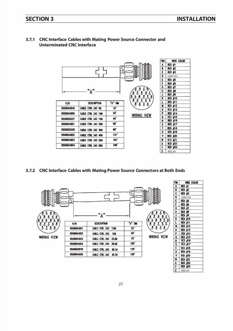
7172019 EPP-360 Plasma Power Source 0558007676
httpslidepdfcomreaderfullepp-360-plasma-power-source-0558007676 3346
33
SECTION 4 OPERATION
3
not used
EPP-360
10K
24 CONDUCTOR CABLE
+
E-STOP ISOLATED CONTACT
CLOSED TO RUN
MARK MODE SELECT
CUT CURRENT REF
CURRENT REF COM J
L
A
G
Z
M
T
Q
Y
S
N
C
D
E
F
H
K
R
U
V
W
X
B
P
CUT CURRENT REF+
MARK MODE SELECT
I mark = (36) X (Vcut cur ref)
CLOSED FOR MARKING
POWER SOURCE FAULT
RED 09
MASTER SELECT - CONNECT H TO R (ALWAYS PRESENT)
RED 22
RED 01
RED 18
RED 13
RED 12
RED 15
RED 23
RED 17
RED 07
RED 11
RED 04
RED 02
RED 14
RED 03
RED 05
RED 08
RED 06
RED 10
RED 16
RED 20
RED 19
RED 21
115V AC NEUTRAL
WC LEVEL (ON W LEVEL OK)
ON WITH FAULT
+
K4
WC LEVEL OFF
WITH FAULT
PA CURRENT SELECT
E-STOP
PA CURRENT SELECT
E-STOP
PA CURRENT SELECT
CNC
(PARALLEL OPERATION ONLY)
Icut = (36) X (Vcut cur ref)
CURRENT HILOCLOSED FOR 720A OPEN FOR 360A
Ipa = (45) X (Vpa cur ref)
+
FOR HI Icut = (72) X (Vcut cur ref)
PLASMA START
PS 24V DC COMMON
HI RANGE (720A)
PLASMA START
FOR LO Icut = (36) X (Vcut cur ref)
15V CNC
COMMON
PA CURRENT SELECT
24V DC
COMMON
PA ON
CNC +15V DC
WC FLOW FAULT ON WITH FLOW OK
CABLE
WIRE ID
ARC ON
+
MASTER SELECT
1 1 5 V
A C N
E U T R A L
+
Plasma System Control
POWER SOURCE FAULT
20K
115V AC H
24V AC
PA ON
PA CURRENT REF
C N C
+ 1 5 V
D C
20K
PA CURRENT REF
ARC ON
not used
GRNYEL
PROCESS CONTROL SELECTION
2 4 -
C O N
D U C T O R
C O N
N E C T O R
CNC ANALOG COMMON
CHASSIS
WC FLOW FAULT OFF WITH LO FLOW
PA1
HALL TRANSDUCER
OPEN FOR INTERNAL CONTROL
+MASTER CURRENT
1 1 5 V
A C
CLOSED FOR EXTERNAL CONTROL
10K
10K
10K
10K
10K
10K
MASTER OUTPUT CURRENT
SIGNAL 10V = 100A
10K
PA0
F U S E
24V24V
15V15V
0 TO 10V0 TO 10V0 TO 10V0 TO 10V
7172019 EPP-360 Plasma Power Source 0558007676
httpslidepdfcomreaderfullepp-360-plasma-power-source-0558007676 3446
34
PA0 PA1 Pilot current in amp
open open 10
closed open 20
open closed 30
closed closed 40
b Remote with Full CNC Mode - (CNC cable pin ldquoVrdquo closed closed for external control) Panelremote switchon the power source is set to REMOTE The CNC should activate the input labeled ldquofull CNC controlrdquo on pinldquoVrdquo of the interconnect cable In this mode all parameters are controlled by the CNC including start currentpilot current and sloping times The control of the pilot current can be done either by logic inputs or by ananalog input If the analog input is less than 05 volts the power source will use the logic inputs PA0 and PA1to provide the requested pilot arc current based on the following combination
SECTION 4 OPERATION
If the analog reference is used 10 VDC will provide 45 amps or 1 V = 45 amps
Marking - Can be done in both panel and remote mode and requires the mark mode select input to be closedby the CNC In the panel mode the maximum marking current (set by the panel potentiometer) is 36 ampsIf SW1-1 (which is open on the control board) is closed the range becomes 0 -18 amps max In the remotemode the marking current is set by the main reference input and 10 VDC will provide 36 amps or 1 V = 36amps of marking current
Cut Current
(amps)
Start Current
(amps)
Pilot Arc Current
Command (amps)
Upslope Time
(msec)
30 20 15 200
50 25 20 250
100 50 25 500
200 100 30 800
300 150 35 900
360 180 40 950
The table used to calculate the initial current pilot current and upslope values are stored in the micro and con-tains the following information
If values other than the table values are used for the cut current the corresponding values are calculated assum-ing a linear slope for all the required parameters
a Partial CNC operation - (CNC cable pin ldquoVrdquo open open for internal control) In this mode of operation thepanelremote switch needs to be in the REMOTE position The CNC should be providing the cut current refer-ence and startstop signal to the power source Based on the cut reference the micro in the power source willcompute the initial current pilot current and upslope time
2 Remote Mode -
7172019 EPP-360 Plasma Power Source 0558007676
httpslidepdfcomreaderfullepp-360-plasma-power-source-0558007676 3546
35
SECTION 4 OPERATION
1 Parallel Mode of operation - Connect power sources together as shown in section 36 Set the panelremoteswitches on both power sources to remote If the units will be used for cutting and both power sources are to
contribute to the cut current value activate the logic input labeled ldquoHI CURRENTrdquo (pin ldquoTrdquo) on the CNC cable Inthis manner a maximum current of 720 amps can be provided for an analog input of 10 VDC from the CNC If theldquoHI CURRENTrdquo input is deactivated the supplemental power source will not provide any output even though it isconnected to the primary power source In marking mode only the primary power source will supply the mark-ing current If alternating marking and cutting operations are done the ldquoHI CURRENTrdquo input can be maintainedand the mark input will control whether both or only one power source will provide output current The markingcurrent range is from 10 to 36 amps and the cut current range is from 30 to 720 amps
44 Sequence of Operation
432 Multiple Power Sources
A Apply power by closing the line (wall) switch The EPP-360 does not contain its own power OnOff switchOnce power is supplied the EPP-360 display board will display ldquoEPP-360rdquo briefly followed by the display ldquoPrxxxrdquo indicating the software program revision number then ldquo0 ampsrdquo and ldquo0 voltsrdquo
B Select Panel Remote setting for current control depending on whether your CNC has remote current con-trol capability
1 If using the ldquoPanelrdquo mode the selected cutting current may be viewed by holding the front panel switchin the ldquoCut Current Presetrdquo position In the ldquoPanelrdquo mode the Pilot Arc Current Initial Current and Up-slope Time are determined by the power source based on the selected cutting current The selectedPilot Arc Current can be viewed by holding the front panel switch in the ldquoPA Current Presetrdquo position Seesection 42 Control Panel
2 If using the ldquoRemoterdquo mode there are two possible modes of operation
a The default mode is similar to the ldquoPanelrdquo mode with the exception that the cutting current com-mand is supplied by the CNC instead of the front panel potentiometer Scaling of the remote cur-rent command is 10 V DC = 36 amps This mode is useful if the CNC does not have the capabilityof controlling the initial current and sloping of the output For remote control connections see theCNC interface diagram
b If your CNC has the capability of controlling Initial Current and Slopes place the PanelRemote switchin ldquoRemoterdquo and supply a contact closure between pins ldquoRrdquo and ldquoVrdquo of the CNC interface connectorIn this mode the CNC must supply the analog signal to control Initial Current Upslope and Cut Cur-rent level Scaling is the same as default mode Pilot Arc current will be controlled by a second 0 ndash 10V DC analog signal if available or by supplying a binary coded signal as defined in the CNC interfacediagram Scaling of the pilot arc signal is 10 V DC = 45 amps
C Begin plasma cutting operation This may require setting of other variables such as gas pressures flow ratesand torch height etc
D If for any reason cutting or marking fails to initiate the EPP-360 should display an error code indicating thereason for the shutdown See ldquoHelp Codesrdquo in the troubleshooting section
7172019 EPP-360 Plasma Power Source 0558007676
httpslidepdfcomreaderfullepp-360-plasma-power-source-0558007676 3646
36
SECTION 4 OPERATION
7172019 EPP-360 Plasma Power Source 0558007676
httpslidepdfcomreaderfullepp-360-plasma-power-source-0558007676 3746
37
SECTION 5 MAINTENANCE
51 General
ELECTRIC SHOCK CAN KILL
SHUT OFF POWER AT THE LINE 983080WALL983081 DISCONNECT BEFORE AT983085TEMPTING ANY MAINTENANCEWARNING
WARNINGEYE HAZARD WHEN USING COMPRESSED AIR TO CLEAN
Wear approved eye protection with side shields when cleaning thebull
power sourceUse only low pressure airbull
CAUTION Maintenance On This Equipment Should Only Be Performed ByTrained Personnel
52 Cleaning
Regularly scheduled cleaning of the power source is required to help keep the unit running trouble free Thefrequency of cleaning depends on environment and use
1 Turn power off at wall disconnect2 Remove side panels3 Use low pressure compressed dry air remove dust from all air passages and components Pay particular
attention to heat sinks in the front of the unit Dust insulates reducing heat dissipation Be sure to wear
eye protection
Air restrictions may cause EPP-360 to over heatThermal Switches may be activated causing interruption of func-tionDo not use air filters on this unitKeep air passages clear of dust and other obstructions
WARNING
CAUTION
ELECTRIC SHOCK HAZARDBE SURE TO REPLACE ANY COVERS REMOVED DURING CLEANING
BEFORE TURNING POWER BACK ON
7172019 EPP-360 Plasma Power Source 0558007676
httpslidepdfcomreaderfullepp-360-plasma-power-source-0558007676 3846
38
SECTION 5 MAINTENANCE
7172019 EPP-360 Plasma Power Source 0558007676
httpslidepdfcomreaderfullepp-360-plasma-power-source-0558007676 3946
39
SECTION 6 TROUBLESHOOTING
ELECTRIC SHOCK CAN KILLDO NOT PERMIT UNTRAINED PERSONS TO INSPECT OR REPAIR THISEQUIPMENT ELECTRICAL WORK MUST BE PERFORMED BY AN EXPE983085RIENCED ELECTRICIAN
WARNING
Stop work immediately if power source does not work properlyHave only trained personnel investigate the causeUse only recommended replacement parts
CAUTION
61 Troubleshooting
Check the problem against the symptoms in the following troubleshooting guide The remedy may be quitesimple If the cause cannot be quickly located shut off the input power open up the unit and perform a simple
visual inspection of all the components and wiring Check for secure terminal connections loose or burned wir-ing or components bulged or leaking capacitors or any other sign of damage or discoloration
The cause of control malfunctions can be found by referring to the sequence of operations electrical schematicsand checking the various components A volt-ohmmeter will be necessary for some of these checks
62 Troubleshooting Guide
As the unit is powered up the display should show EPP-360 for one second and then show the program numbersuch as Pr 301 or higher If the display remains blank look for the following
a loose or missing display cable between the main control board and the display board b lack of +15 volt bias supply which could be caused by blown fuses F1 or F2 c an open circuit breaker (CB1) on the front panelIf the unit shows Error 5 after the program number display times out look for a closed start switch To reset theunit simply open the start switch At this point the display should show 0rsquos in both windows If the power sourceis not connected to a CNC at power up the emergency stop relay (K4) in the power source is not energized pre-venting any relay operation in the power source itself
If the CNC has been booted up the display should read 0 for both the volts and amps The unit will not respondto a start signal until itrsquos master select input (pin H on J1) is connected to the ldquoHOTldquo side of 115 input (masterselect input) This connection is handled in the CNC to primary supply cable Note all inputs from the CNC arerelay closures providing 115 V AC inputs to the isolation board (PCB4 in the power source) The isolation board
converts these inputs to open collector type outputs The control will monitor various signals in the idle modeand will shut down with an error indication if the condition is not satisfactory Errors 1 3 4 5 9 or 12 (See 63Help code list)As the start switch is activated and the unit is being prepared for cutting additional conditions are being moni-tored The resulting error conditions are as follows Error 2 6 8 12 13 14 15 17 18 19 or 113 (See 63 Help codelist)
7172019 EPP-360 Plasma Power Source 0558007676
httpslidepdfcomreaderfullepp-360-plasma-power-source-0558007676 4046
40
SECTION 6 TROUBLESHOOTING
63 Help Code list
Error number displays and their meaning for the EPP-360 power supply
Error 1 +- 15 deviation in the idle mode is exceeded
Error 2 Line voltage during cut drops by more than 20
Error 3 Problem with the bias supplies on the control board The +15 and -15 volt supplies are not balanced boardshould be replaced
Error 4 Thermal switch has opened Unit is disabled until overheated component cools down Look for fans notworking or restrictions on input or output louvers
Error 5 The start switch from the CNC was already on when the power source was powered up Unit will not befunctional until start signal is removed and then reapplied
Error 6 Ignition did not take place during the 10 seconds allowed for arc ignitionNote This should rarely occur since the CNC has a much shorter time allowed for the ignition time andwill reset the power source to idle
Error 7 Not used
Error 8 Electrode current was present before the PWM was enabled Most likely caused by an electrode to nozzle
short on the torchError 9 Open circuit voltage in idle mode was over 40 volts Possible cause leaky IGBTs faulty PWM drive
Error 10 Open circuit voltage is over 70 volts when unit is powered up Possible cause leaky IGBTrsquos faulty PWM
Error 11 Not used
Error 12 Shut down due to single phasing Fuse blown in supply line circuit
Error 13 Open circuit voltage did not reach 300 volts in the allowed time Check PWM circuit amp E-Stop on J1
Error 14 Ambient temperature exceeded 55 C in control enclosure
Error 15 Bus voltage did not reach 100 volts during the allowed time Bus charge relay or surge limiting resistorsdefective
Error 16 Not used
Error 17 IGBT driver board errorError 18 Cutting voltage fell below 70 volts during cutting or below 40 volts during marking
Error 19 Master is requested to engage slave power supply but slave is not present
Error 20 Open circuit voltage detected before PWM was engaged
Error 113 Error detected in slave power supply
HELP CODES01 LINE VOLT IDLE 08 TORCH ERROR 15 BUS CHARGER FAILURE
02 LINE VOLT CUTTING 09 OCV OVER 40V IDLE 17 IGBT DRIVER ERROR03 CONTROL BIAS 10 OCV OVER 70V STARTUP 18 CUTMARK VOLTAGE TOO LOW
04 THERMAL (SWITCH OPEN) 12 1Ф OPERATION SHUTDOWN 19 SLAVE PS NOT DETECTED
05 START ON POWER UP 13 OCV FAILURE 20 SHORTED IGBT BUS CHARGED
06 FAIL TO FIRE 14 AMBIENT TEMP 113 SLAVE PS ERROR
7172019 EPP-360 Plasma Power Source 0558007676
httpslidepdfcomreaderfullepp-360-plasma-power-source-0558007676 4146
41
64 Fault Isolation
641 Fans Not Working
Problem Possible Cause Action
All 3 fans do not run
This is normal when not cutting
Fans run only when ldquoContactor Onrdquo
signal is received
None
1 or 2 fans do not run
Broken or disconnected wire in fan
motor circuitRepair wire
Faulty fan(s) Replace fans
642 Torch Will Not Fire
SECTION 6 TROUBLESHOOTING
Problem Possible Cause Action
Main Arc Transfers to the work with ashort ldquopoprdquo placing only a small dimplein the work
Remote control removes the startsignal when the main arc transfers tothe work
PanelRemote switch in ldquoRemoterdquo withno remote control of the current
Place PanelRemote switch in ldquoPanelrdquoposition
Remote current control present butsignal missing
Check for current reference signalbetween J and L on 24 pin receptacle -should be between 05 - 10 volts
(10 volts = 360 amps)Current pot set too low Increase current pot setting
Arc does not start There is no arc at thetorch Open circuit voltage is OK
Open connection between the powersource positive output and the work
Repair connection
Pilot current andor start current shouldbe increased for better starts whenusing consumables for 100A or higher(Refer to process data included in torchmanuals)
Increase pilot current (Refer to processdata included in torch manuals)
Faulty PCB1 Replace PCB1
7172019 EPP-360 Plasma Power Source 0558007676
httpslidepdfcomreaderfullepp-360-plasma-power-source-0558007676 4246
42
SECTION 6 TROUBLESHOOTING
7172019 EPP-360 Plasma Power Source 0558007676
httpslidepdfcomreaderfullepp-360-plasma-power-source-0558007676 4346
43
SECTION 7 REPLACEMENT PARTS
71 General
Always provide the serial number of the unit on which the parts will be used The serial number is stamped onthe unit serial number plate
To ensure proper operation it is recommended that only genuine ESAB parts and products be used with thisequipment The use of non-ESAB parts may void your warranty
Replacement parts may be ordered from your ESAB Distributor
Be sure to indicate any special shipping instructions when ordering replacement parts
Refer to the Communications Guide located on the back page of this manual for a list of customer service phonenumbers
72 Ordering
Items listed in the following Bill of Materials that do not have a part numbershown are not available from ESAB as a replaceable item and cannot be
ordered Descriptions are shown for reference only Please use local retailhardware outlets as a source for these items
Note
70 Replacement Parts
NoteReplacement Parts Schematics and Wiring Diagrams areprinted on 2794mm x 4318mm (11rdquo x 17rdquo) paper and are
included inside the back cover of this manual
EPP-360 Information
Part Number
EPP-360 460V60Hz
EPP-360 575VCSA 60Hz
0558006832 0558006833
7172019 EPP-360 Plasma Power Source 0558007676
httpslidepdfcomreaderfullepp-360-plasma-power-source-0558007676 4446
44
NOTES
7172019 EPP-360 Plasma Power Source 0558007676
httpslidepdfcomreaderfullepp-360-plasma-power-source-0558007676 4546
45
REVISION HISTORY
Original release - 0120081Revision 022008 - Updated replacement parts and BOM various other minor changes2Revision 062008 - Updated replacement parts and BOM various other minor changes3Revision 092008 - Updated replacement parts and BOM4
Revision 042009 - Updated replacement parts and BOM5
7172019 EPP-360 Plasma Power Source 0558007676
httpslidepdfcomreaderfullepp-360-plasma-power-source-0558007676 4646
A CUSTOMER SERVICE QUESTIONS Telephone (800)362-7080 Fax (800) 634-7548 Hours 800 AM to 700 PM EST Order Entry Product Availability Pricing Order Information Returns
B ENGINEERING SERVICE Telephone (843) 664-4416 Fax (800) 446-5693 Hours 730 AM to 500 PM EST Warranty Returns Authorized Repair Stations Welding Equipment Troubleshooting
C TECHNICAL SERVICE Telephone (800) ESAB-123 Fax (843) 664- 4452 Hours 800 AM to 500 PM EST Part Numbers Technical Applications Specifications Equipment Recommendations
D LITERATURE REQUESTS Telephone (843) 664-5562 Fax (843) 664-5548 Hours 730 AM to 400 PM EST
E WELDING EQUIPMENT REPAIRSTelephone (843) 664-4487 Fax (843) 664-5557 Hours 730 AM to 330 PM EST
Repair Estimates Repair Status
F WELDING EQUIPMENT TRAINING Telephone (843)664-4428 Fax (843) 679-5864 Hours 730 AM to 400 PM EST Training School Information and Registrations
G WELDING PROCESS ASSISTANCE Telephone (800) ESAB-123 Hours 730 AM to 400 PM EST
H TECHNICAL ASST CONSUMABLES
Telephone (800) 933-7070 Hours 730 AM to 500 PM EST
IF YOU DO NOT KNOW WHOM TO CALL
Telephone (800) ESAB-123 Fax (843) 664-4462
Hours 730 AM to 500 PM ESTor
visit us on the web at httpwwwesabnacomThe ESAB web site offers
Comprehensive Product InformationMaterial Safety Data Sheets
Warranty RegistrationInstruction Literature Download Library
Distributor LocatorGlobal Company Information
Press ReleasesCustomer Feedback amp Support
ESAB Welding amp Cutting Products Florence SC Welding EquipmentCOMMUNICATION GUIDE - CUSTOMER SERVICES
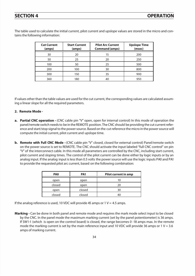
7172019 EPP-360 Plasma Power Source 0558007676
httpslidepdfcomreaderfullepp-360-plasma-power-source-0558007676 4646
A CUSTOMER SERVICE QUESTIONS Telephone (800)362-7080 Fax (800) 634-7548 Hours 800 AM to 700 PM EST Order Entry Product Availability Pricing Order Information Returns
B ENGINEERING SERVICE Telephone (843) 664-4416 Fax (800) 446-5693 Hours 730 AM to 500 PM EST Warranty Returns Authorized Repair Stations Welding Equipment Troubleshooting
C TECHNICAL SERVICE Telephone (800) ESAB-123 Fax (843) 664- 4452 Hours 800 AM to 500 PM EST Part Numbers Technical Applications Specifications Equipment Recommendations
D LITERATURE REQUESTS Telephone (843) 664-5562 Fax (843) 664-5548 Hours 730 AM to 400 PM EST
E WELDING EQUIPMENT REPAIRSTelephone (843) 664-4487 Fax (843) 664-5557 Hours 730 AM to 330 PM EST
Repair Estimates Repair Status
F WELDING EQUIPMENT TRAINING Telephone (843)664-4428 Fax (843) 679-5864 Hours 730 AM to 400 PM EST Training School Information and Registrations
G WELDING PROCESS ASSISTANCE Telephone (800) ESAB-123 Hours 730 AM to 400 PM EST
H TECHNICAL ASST CONSUMABLES
Telephone (800) 933-7070 Hours 730 AM to 500 PM EST
IF YOU DO NOT KNOW WHOM TO CALL
Telephone (800) ESAB-123 Fax (843) 664-4462
Hours 730 AM to 500 PM ESTor
visit us on the web at httpwwwesabnacomThe ESAB web site offers
Comprehensive Product InformationMaterial Safety Data Sheets
Warranty RegistrationInstruction Literature Download Library
Distributor LocatorGlobal Company Information
Press ReleasesCustomer Feedback amp Support
ESAB Welding amp Cutting Products Florence SC Welding EquipmentCOMMUNICATION GUIDE - CUSTOMER SERVICES