epcos product profile 2012 film capacitors · types of ac motor controllers are currently in...
TRANSCRIPT

www.epcos.com
EPCOS Product Profile 2012
Film Capacitorsfor Industrial Applications


3© EPCOS AG 2012
Film Capacitors for Industrial Applications
Contents
Important notes 4
Introduction 5
Film capacitors for drives 6
Film capacitors for uninterruptible power supplies 7
Film capacitors for photovoltaic systems 8
Film capacitors for switch-mode power supplies 9
Film capacitors for electrical welding equipment 10
Film capacitors for lighting: electronic ballast 11
Film capacitors for lighting: LEDs 12
Film capacitors for power supplies in smart energy meters 13
Film capacitors overview 14
Film capacitors functions 17
General technical information 22
Quick guide to operating conditions vs. technical parameters 26
Technical parameters 27
Cautions and warnings 29
Get in contact 30

4 © EPCOS AG 2012
Important Notes
The following applies to all products named in this publication:
1. Some parts of this publication contain statements about the suitability of our products for certain ar-eas of application. These statements are based on our knowledge of typical requirements that are often placed on our products in the areas of application concerned. We nevertheless expressly point out that such state-ments cannot be regarded as binding statements about the suitability of our products for a particular customer application. As a rule, EPCOS is either unfa-miliar with individual customer applications or less famil-iar with them than the customers themselves. For these reasons, it is always ultimately incumbent on the cus-tomer to check and decide whether an EPCOS product with the properties described in the product specification is suitable for use in a particular customer application.
2. We also point out that in individual cases, a malfunc-tion of electronic components or failure before the end of their usual service life cannot be completely ruled out in the current state of the art, even if they are operated as specified. In customer applications re-quiring a very high level of operational safety and espe-cially in customer applications in which the malfunction or failure of an electronic component could endanger human life or health (e.g. in accident prevention or life-saving systems), it must therefore be ensured by means of suitable design of the customer application or other action taken by the customer (e.g. installation of protec-tive circuitry or redundancy) that no injury or damage is sustained by third parties in the event of malfunction or failure of an electronic component.
3. The warnings, cautions and product-specific notes must be observed.
4. In order to satisfy certain technical requirements, some of the products described in this publica-tion may contain substances subject to restric-tions in certain jurisdictions (e.g. because they are classed as hazardous). Useful information on this will be found in our Material Data Sheets on the Internet (www.epcos.com/material). Should you have any more detailed questions, please contact our sales offices.
5. We constantly strive to improve our products. Conse-quently, the products described in this publication may change from time to time. The same is true of the corresponding product specifications. Please check therefore to what extent product descriptions and speci-fications contained in this publication are still applicable before or when you place an order.
We also reserve the right to discontinue production and delivery of products. Consequently, we cannot guarantee that all products named in this publication will always be available.
The aforementioned does not apply in the case of indi-vidual agreements deviating from the foregoing for cus-tomer-specific products.
6. Unless otherwise agreed in individual contracts, all or-ders are subject to the current version of the “Gener-al Terms of Delivery for Products and Services in the Electrical Industry” published by the German Electri-cal and Electronics Industry Association (ZVEI).
7. The trade names EPCOS, BAOKE, Alu-X, CeraDiode, CSMP, CSSP, CTVS, DeltaCap, DigiSiMic, DSSP, FormFit, MiniBlue, MiniCell, MKD, MKK, MLSC, MotorCap, PCC, PhaseCap, PhaseCube, PhaseMod, PhiCap, SIFERRIT, SIFI, SIKOREL, SilverCap, SIMDAD, SiMic, SIMID, SineFormer, SIOV, SIP5D, SIP5K, ThermoFuse, WindCap are trademarks registered or pending in Europe and in other countries. Further information will be found on the Internet at www.epcos.com/trademarks.

5Please read Important notes on page 4 and Cautions and warnings on page 29.© EPCOS AG 2012
Introduction
Film capacitors as a reliable solutionThe self-healing capability of film capacitors is one of their most important features. It protects them against cata-strophic failures and makes them highly reliable compared with other technologies. They also offer excellent thermal stability. In addition, their key electrical parameters remain constant when the voltage is changed thanks to the high electrical stability of this technology. Low ESR values and high Irms handling capability are other important charac-teristics of film capacitors, related to their self-heating in operation. They are needed in applications operating with high-frequency ripple currents.
RoHS Directive 2002/95/EC (“RoHS”) from January 27th, 2003, (OJ No. L 37/19 of February 13, 2003) defines the restric-tions for hazardous substances used in electrical and elec-tronic equipment. Article 4 (1), in force since July 1, 2006 prohibits electric light bulbs and luminaires containing lead, mercury, cadmium, hexavalent chromium, polybrominated biphenyls (PBB) and polybrominated diphenylethers (PBDE) for domestic use and in electrical and electronic equip-ment to be put on the market. This directive does not apply to components. EPCOS nevertheless supplies products – listed as RoHS-compatible – ready to use with electri-cal and electronic equipment of the categories mentioned above. As the banned substances cannot be replaced in all applications, exemptions are granted in the RoHS Annex. This has been amended by Directive 2005/717/EC of October 15th, 2005 and Directive 2005/747/EC of October 25th, 2005.Due to natural impurities, a zero level of restricted sub-stances cannot be achieved. Threshold levels had been published in Directive 2005/618/2005 of August 2005, which amends 2002/95/EC (RoHS).
REACH Regulation (EC) No 1907/2006 concerning Registration, Evaluation, Authorization and Restriction of Chemicals (REACH for short) has been in force since June 1, 2007. Producers, importers and other suppliers of articles con-taining Substances of Very High Concern (SVHC) included in the candidate list according to article 59 (1, 10) of the REACH Regulation in a concentration above 0.1% by weight must provide the information that is available to them.EPCOS is taking every effort to discontinue the use of this SVHC as early as possible. The current status can be found at www.epcos.com/reach.As of today no FILM capacitor contains any substance included in SVHC list in concentrations higher than allowed.
HalogensHalogen free capacitors as defined according to IEC 61249-2-21 Clause 3.1 (< 900 ppm for Cl, Br and < 1500 ppm for Cl + Br per product weight), are available under request.
Applicable standardsIn terms of mechanical and electrical performance, IEC 60384-2, IEC 60384-16 and IEC 60384-14 are the sector standards for MKT, MKP and EMI suppression capacitors.Capacitors designed to be used specifically in power electronic equipment must also comply with the interna-tional IEC 61071 standard. Its objective is to describe the basic performance, testing, rating and safety rules of all the capacitors used in semiconductor switching as well as protection, filtering and energy-storage applications.
1. Málaga plant (Spain), 2. Zhuhai plant (China), 3. Nashik plant (India), 4. Gravataí plant (Brazil)
1 2 3 4

6 © EPCOS AG 2012Please read Important notes on page 4 and Cautions and warnings on page 29.
Film Capacitors for Drives
Block diagram
KMK1364-9
3 x Cx
Cy
EMC filtering AC/DCconverter
DC link
CBUS
DC/ACinverter
CS
Output filtering
M
Cx, Cy CF
Characteristics
Function Class Type Technical data Features
EMC filteringCX
MKT AC B32932 … B32936 305 V AC 47 nF … 10 µF
+85 °C / 85% RH / 1000 hConnection in series with mains
X1 B32911 … B32916 330 V AC 10 nF … 6.8 µF
High pulse across the line UL/ENEC
X2 B32921 … B32928 305 V AC 10 nF … 45 µF
General purpose across the line UL/ENEC
EMC filteringCY
Y1 B81123 250 V AC 1 … 10 nF
Reinforced insulation line to ground UL/ENEC
Y2 B32021 … B32026 300 V AC 1 nF … 1 µF
Basic insulation line to ground UL/ENEC
DC linkDC filteringCBUS
MKP B32674 … B32678 B32774 … B32778
450 … 1300 V DC 0.47 … 200 µF
Very high ripple currentSmall size
MKT B32520 … B32529 63 … 630 V DC 1 nF … 220 µF
Up to +125 °C
DC/AC inverter: snubber, resonantCS
MFP B32632 … B32634 B32686
250 … 3000 V DC 1 … 680 nF
Very high dV/dt
MKP B32651 … B32656 B32656S B32671L … B32672L
250 … 2000 V DC1 nF … 220 µF 1 nF … 8.2 µF
General purpose, lead wiresStrap terminalsHigh V AC
Output filteringCF
MKP B32794 … B32798 250 … 400 V AC 820 nF … 75 µF
Up to +105 °COptimized AC voltage with small dimensionsHigh ripple current
GeneralThe function of an adjustable electrical drive is to control the speed, torque, acceleration, deceleration and direction of rotation of the motor driving a machine. Drives may be of direct current or adjustable frequency type (DC and AC drives, respectively). Because of their simplicity, ease of use, reliability and favorable cost, DC drives have been the preferred solution for industrial applications for many years. On the other hand, adjustable frequency AC motor drive controllers, frequently known as inverters, are typically more complex than DC controllers since they must per-form two power-section functions: conversion from AC to DC and finally back from DC to AC. A number of different types of AC motor controllers are currently in widespread use as general purpose drives, i.e. pulse width modulated
(PWM), current source input (CSI), and load commutated inverter (LCI) types. Each type offers specific benefits and characteristics, and the selection criterion is based on the final application requirements in terms of voltage and power.

7© EPCOS AG 2012 Please read Important notes on page 4 and Cautions and warnings on page 29.
Film Capacitors for Uninterruptible Power Supplies
Block diagram
KMK1365-2
3 x Cx
Cy
EMC filtering AC/DCconverter
DC link
CBUS
DC/ACinverter
CS
Output filtering
M
Cx, Cy CF
Characteristics
Function Class Type Technical data Features
EMC filteringCX
X1 B32911 … B32916 330 V AC10 nF … 6.8 µF
High pulse across the line UL/ENEC
X2 B32921 … B32928 305 V AC10 nF … 45 µF
General purpose across the line UL/ENEC
EMC filteringCY
Y1 B81123 250 V AC1 … 10 nF
Reinforced insulation line to ground UL/ENEC
Y2 B32021 … B32026 300 V AC1 nF … 1 µF
Basic insulation line to ground UL/ENEC
DC linkDC filteringCBUS
MKP B32674 … B32678B32774 … B32778
450 … 1300 V DC0.47 … 200 µF
Very high ripple currentSmall size
DC/AC inverter: snubberCS
MFP B32632 … B32634B32686
630 … 3000 V DC 1 … 680 nF
Very high dV/dt
MKP B32651 … B32656B32656S B32671L … B32672L
250 … 2000 V DC1 nF … 8.2 µF
General purpose, lead wiresStrap terminalsHigh V AC
Output filteringCF
MKP B32794 … B32798 250 … 400 V AC0.82 … 75 µF
Up to 105 °COptimized AC voltage with small dimensionsHigh ripple current
GeneralUninterruptible power supplies (UPS) are designed to protect the load from any interruptions in the line, including spikes, over- and under-voltages and blackouts, by sup-plying the needed voltage to the output. In case of a black-out, the battery will feed the output from a few minutes to several hours depending on its size. A UPS can also be understood as a system designed to protect the load against instabilities in the power line, which is the best way of ensuring the reliability of the load over its operating life. Depending on their configuration, three major UPS topolo-gies may be identified: off-line, line interactive and on-line.

8 © EPCOS AG 2012Please read Important notes on page 4 and Cautions and warnings on page 29.
Film Capacitors for Photovoltaic Systems
Block diagram
KMK1366-H
DC link
CDC
PVLoads,mains
DC/DCconverter
DC/ACinverter
Output filtering
CBUS CS CF
EMC filtering
Cx, Cy
Characteristics
Function Class Type Technical data Features
EMC filteringCX
MKT AC B32932 … B32936 305 V AC 47 nF … 10 µF
+85 °C / 85% RH / 1000 hConnection in series with mains
X1 B32911 … B32916 330 V AC 10 nF … 6.8 µF
High pulse across the line UL/ENEC
X2 B32921 … B32928 305 V AC 10 nF … 45 µF
General purpose across the line UL/ENEC
EMC filteringCY
Y1 B81123 250 V AC 1 … 10 nF
Reinforced insulation line to ground UL/ENEC
Y2 B32021 … B32026 300 V AC 1 nF … 1 µF
Basic insulation line to ground UL/ENEC
DC/DC converter, DC linkDC filteringCDC, CBUS
MKP B32674 … B32678B32774 … B32778
450 … 1300 V DC 0.47 … 200 µF
Very high ripple currentSmall size
MKT B32520 … B32529 63 … 630 V DC 1 nF … 220 µF
Up to +125 °C
DC/AC converter: snubber, resonantCS
MFP B32632 … B32634 B32686
630 … 3000 V DC 1 … 330 nF
Very high dV/dt
MKP B32651 … B32656 B32656S B32671L … B32672L
250 … 2000 V DC 1 nF … 8.2 µF
General purpose, lead wiresStrap terminalsHigh V AC
Output filteringCF
MKP B32794 … B32798 250 … 400 V AC 0.82 … 75 µF
Up to +105 °C Optimized AC voltage with small dimensions High ripple current
GeneralCapacitors are widely used in photovoltaic systems as protecting elements for people and equipment. Film capacitors have also become a common solution in filters and more specifically in solar inverters. These are spe-cial devices that must fulfill several functions in the solar generator, assuring not only DC-AC conversion or energy storage, but also output power quality, various protection mechanisms and system checks. Additional requirements for these components, which are increasingly demanded by final customers and developers, are high efficiency and high reliability. These requirements have driven inverter development towards simpler topologies and structures, with fewer components and high modularity.

9© EPCOS AG 2012 Please read Important notes on page 4 and Cautions and warnings on page 29.
Film Capacitors for Switch-Mode Power Supplies
Block diagram
KMK1367-L
EMC filtering PFC & DC link
Load+C5 C6
Mains
Cx, Cy
AC/DCconverter
DC/DC converter
CDC CS
Characteristics
Function Class Type Technical data Features
EMC filteringCX
MKT AC B32932 … B32936 305 V AC 47 nF … 10 µF
85 °C / 85% RH / 1000 hConnection in series with mains UL/ENEC
X1 B32911 … B32916 330 V AC 10 nF … 6.8 µF
High pulse across the line UL/ENEC
X2 B32921 … B32928 305 V AC 10 nF … 45 µF
General purpose across the line UL/ENEC
EMC filteringCY
Y1 B81123 250 V AC 1 … 10 nF
Reinforced insulation line to ground UL/ENEC
Y2 B32021 … B32026 300 V AC 1 nF … 1 µF
Basic insulation line to ground UL/ENEC
Power factor correction & DC linkDC filteringCDC
MKP B32671P … B32673PB32671Z … B32673Z
450 … 630 V DC 10 nF … 2.2 µF
Small sizeHigh ripple current
MKT B32520 … B32529 63 … 630 V DC 1 nF … 220 µF
Up to +125 °CSmall size for 450 V DC
DC/DC converter: snubber, resonantCS
MKP B32651 … B32656B32671L … B32672L
250 … 2000 V DC 1 nF … 8.2 µF
High AC voltage for B3267*L, miniaturized High RMS current
GeneralA switch-mode power supply (SMPS) is a power electronic converter that basically converts the input voltage into a DC output voltage of a different magnitude. In general, most SMPS are connected to the power line, so the AC voltage coming from the line must be converted into the DC voltage needed at the input of the real DC/DC con-verter. That is why a rectifier is usually present at the input of any SMPS. SMPS offer higher efficiencies with more compact mechanical dimensions than other traditional DC/DC converters, which is an advantage for portable devices. However, they are more complex and may generate more electromagnetic noise – due to the switching operation of the semiconductors – which must be efficiently sup-pressed. Various topologies with different features (buck, boost, flyback, half-bridge, full-bridge etc.) are available depending on the required output power.

10 © EPCOS AG 2012Please read Important notes on page 4 and Cautions and warnings on page 29.
Film Capacitors for Electrical Welding Equipment
GeneralElectrical welding equipment uses electricity in order to generate the heat needed for joining metal parts. In the past, welding power supplies were based on large and heavy metal transformers that operated at 50 or 60 Hz and were relatively inefficient. Advanced power supplies based on inverter technology have become increasingly popular and have changed the design and capability of modern welding equipment. This new equipment, operating with high frequency signals, is much more efficient and can be even more compact and lightweight thanks to design optimization, where the use of film capacitors can play a key role.
Block diagram
KMK1368-E
EMC filtering DC link Output rectifier
CF
CF
Mains
AC/DCconverter
DC/ACconverter
CBUS CS
3 x Cx
Cy
Cx, Cy
Characteristics
Function Class Type Technical data Features
EMC filteringCX
X1 B32911 … B32916 330 V AC 10 nF … 6.8 µF
High pulse across the line UL/ENEC
X2 B32921 … B32928 305 V AC 10 nF … 45 µF
General purpose across the line UL/ENEC
EMC filteringCY
Y1 B81123 250 V AC 1 … 10 nF
Reinforced insulation line to ground UL/ENEC
Y2 B32021 … B32026 300 V AC 1 nF … 1 µF
Basic insulation line to ground UL/ENEC
DC linkDC filteringCBUS
MKP B32674 … B32678B32774 … B32778
450 … 1300 V DC 0.47 … 200 µF
Very high ripple currentSmall size
DC/AC converter: snubber, resonantCS
MFP B32632 … B32634 B32686
1 … 330 nF 630 … 3000 V DC
Very high dV/dt
MKP B32651 … B32656 B32656S
250 … 2000 V DC 1 nF … 8.2 µF
General purpose, lead wiresStrap terminals
Filtering in output rectifierCF
MKP B32674 … B32678 450 … 1050 V DC0.47 … 60 µF
Up to +105 °C
B32794 … B32798 250 … 400 V AC0.82 … 75 µF
Up to +105 °COptimized AC voltage with small dimensions

11© EPCOS AG 2012 Please read Important notes on page 4 and Cautions and warnings on page 29.
Film Capacitors for Lighting: Electronic Ballast
Block diagram
KMK1369-1
EMC filtering PFC & DC link DC/AC inverter
+C5 C6
Mains
AC/DCconverter
Cx, Cy CSCDC
Characteristics
Function Class Type Technical data Features
EMC filteringCX
X2 B32921 … B32928 305 V AC 10 nF … 45 µF
General purpose across the line UL/ENEC
EMC filteringCY
Y2 B32021 … B32026 300 V AC 1 nF … 1 µF
Basic insulation line to ground UL/ENEC
Power factor correction & DC linkDC filteringCDC
MKP B32671P … B32673PB32671Z … B32673Z
450 … 630 V DC 10 nF … 2.2 µF
Small sizeHigh ripple current
MKT B32520 … B32529 63 … 630 V DC 1 nF … 220 µF
Up to +125 °CSmall size for 450 V DC
DC/AC inverter: snubber, blocking, resonant, strikingCS
MFP B32632 … B32634 250 … 3000 V DC 160 … 1000 V AC 1 nF … 8.2 µF
Very high dV/dt for HID
MKP B32651 … B32656B32656S B32671L … B32672L
High RMS current, lead wiresStrap terminalsHigh AC voltage, miniaturized
GeneralNew designs in lighting include advanced HID devices and intelligent ballast. The special features of these designs may be summarized as offering very high efficiency, opera-tion with a wide range of input voltages (85-305 Vac) and long-term reliability. The demand for high reliability has led to the widespread use of film capacitors for these designs. Film capacitors are useful not only in PFC and DC/DC con-verters, but also in LC filters, as snubbers. They also pro-tect the circuit board against overload and short circuits, open loops in any stage and input overvoltages. EMC filter capacitors are ideally suited for this purpose.

12 © EPCOS AG 2012Please read Important notes on page 4 and Cautions and warnings on page 29.
Film Capacitors for Lighting: LEDs
Block diagram
KMK1370-3
EMC filtering PFC & DC link
+
DC/DC converterAC/DCconverter
CS, COUTCDCCx, Cy
C5 C6
Characteristics
Function Class Type Technical data Features
EMC filteringCX
X2 B32921 … B32928 305 V AC 10 nF … 45 µF
General purpose across the line UL/ENEC
EMC filteringCY
Y2 B32021 … B32026 300 V AC 1 nF … 1 µF
Basic insulation line to ground UL/ENEC
Power factor correction & DC linkDC filteringCDC
MKP B32671P … B32673PB32671Z … B32673Z
450 … 630 V DC10 nF … 2.2 µF
Small sizeHigh ripple current
MKT B32520 … B32529B32560 … B32564
63 … 630 V DC 1 nF … 220 µF
Up to +125 °CSmall size for 450 V DC
DC/DC converter: snubber resonantCS
MKP B32651 … B32656 B32656SB32671L … B32672L
250 … 2000 V DC1 nF … 8.2 µF
High RMS current, lead wiresStrap terminalsHigh AC voltage, miniaturized
COUT MKP B32774 … B32778 63 … 1300 V DC0.47 … 200 µF
Small size
MKT B32520 … B32529B32560 … B32564
63 … 630 V DC 1 nF … 220 µF
Up to +125 °CUncoated capacitor
GeneralLEDs have become an important light source for vehicles, traffic signals, control lighting, street lighting and even in general lighting applications.In addition to their miniature size LED systems offer a long list of impressive features: exceptional lifetime of up to 100 000 hours, shock-resistance, and high efficiency, not to mention the fact that they emit zero UV radiation, are free of heavy metals, and offer quick start and dimming capabilities. Film capacitors offer the high reliability and operating life required in LED applications.

13© EPCOS AG 2012 Please read Important notes on page 4 and Cautions and warnings on page 29.
Film Capacitors for Power Supplies in Smart Energy Meters
Block diagram
KMK1309-8
+
LR1
C2
D2
D1
N
C1
Characteristics
Function Class Type Technical data Features
Voltage dividerC1
MKP B32651 … B32656 200 … 250 V AC33 nF … 4.7 µF
Connection in series with mains, see note High RMS vs. frequencyHigh dV/dt
Note: Overvoltage protection is recommended as it is not a UL / ENEC approved device
MKT AC B32932 … B32936 305 V AC47 nF … 10 µF
Connection in series with mainsHigh capacitance stability under +85 °C / 85% RH/ AC voltage.
UL / ENEC approval for C ≤ 2.2 µF
GeneralIn recent years, the power meter market has experienced huge growth due to the increased awareness of the need to reduce energy consumption. Power meters are normally situated outdoors, therefore likely to be exposed to harsh climatic conditions (high humidity levels, elevated tempera-tures which may vary hour by hour). As a consequence, they require components that are highly reliable, stable and have a long lifetime, allowing zero maintenance throughout their operation. Key components used in a typical power meter include metallized film capacitors, which form part of a “capacitive power supply” mounted in series with the power network. When subjected to harsh climatic condi-tions, capacitance stability is essential for the long-term operation of the power meter.

14 © EPCOS AG 2012Please read Important notes on page 4 and Cautions and warnings on page 29.
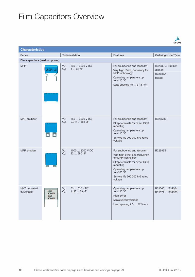
Film Capacitors Overview
Characteristics
Series Technical data Features Ordering code/ Type
Film capacitors (medium power)
X2 VRMS: 305 V AC CR: 10 nF … 45 µF
X2 (2 500 V) class for interference suppression and EMC
Approved acc. to international standards
Lead spacing 10 … 52.5 mm
B32921 … B32928
X1 VRMS: 330 V AC CR: 10 nF … 6.8 µF
X1 (4 000 V) class for interference suppression and EMC
Approved acc. to international standards
Across the line connection
Lead spacing 10 … 37.5 mm
B32911 … B32916
Y2 VRMS: 300 V AC CR: 1 nF … 1 µF
Y2 (5 000 V) class for interference suppression and EMC
Approved acc. to international standards
Line to ground connection
Lead spacing 10 … 37.5 mm
B32021 … B32026
Y1 VRMS: 250 V AC CR: 1 … 10 nF
Y1 (8 000 V) class for interference suppression and EMC
Approved acc. to international standards
Line to ground connection
Lead spacing 15 … 22.5 mm
B81123
MKT AC
heavy duty
VRMS: 305 V AC CR: 47 nF … 10 µF
+85 °C/85% RH/1 000 h/240 V AC
X2 safety class per UL/IEC (C ≤ 2.2 μF)
High stability on capacitance
B32932 … B32936
MKP AC
filtering
VRMS: 250 … 400 V AC CR: 0.82 … 75 µF
Operating temperature up to +105 °C
Output AC filtering
Optimized AC voltage performance with small dimensions
High ripple current/ frequency capability
B32794 … B32798

15© EPCOS AG 2012 Please read Important notes on page 4 and Cautions and warnings on page 29.
Film Capacitors Overview
Characteristics
Series Technical data Features Ordering code/ Type
Film capacitors (medium power)
MKP DC link & DC filtering
VR: 450 … 1300 V DC CR: 1.5 … 200 µF
High-density series, compact
Operating temperature up to +105 °C
Service life 100 000 h at 1.0 · VR, +70 °C
High mechanical stability due to 4-pin terminals
2- and 4-pin versions
Lead spacing 27.5 … 52.5 mm
B32774 … B32778
VR: 300 … 875 V DC CR: 0.47 … 60 µF
High power: higher RMS current capability than B3277x
Operating temperature up to +105 °C
Service life 100 000 h at 1.0 · VR, +70 °C
High mechanical stability due to 4-pin terminals
2- and 4-pin versions
Lead spacing 27.5 … 52.5 mm
B32674 … B32678
MKT DC link & DC filtering
VR: 63 … 630 V DC CR: 1 nF … 220 µF
Low voltage DC-link applications
Operating temperature up to +125 °C
Service life 200 000 h at 1.0 · VR, +70 °C
B32520 … B32529
MKP general purpose
VR: 250 … 2000 V DC CR: 1 nF … 8.2 µF
For snubbering, resonant and switching B3267xL for high frequency AC loads and pulses
Operating temperature up to +105 °C
Possibility of AC and/ or DC operation
High dv/dt and RMS current capability
Lead spacing 10 … 37.5 mm
B32651 … B32656
B32671L … B32672L
MKP PFC (power
factor corection)
VR: 450 … 630 V DC CR: 0.010 … 2.2 µF
Operating temperature up to +125 °C
Specially designed for PFC stage
Lead spacing 10 … 22.5 mm
B32671Z …
B32673Z
VR: 450 … 630 V DC CR: 0.068 … 2.2 μF
Operating temperature up to +125 °C
Specially designed for PFC stage @ 450 ... 630 VDC
B32671P …
B32673P
16 © EPCOS AG 2012Please read Important notes on page 4 and Cautions and warnings on page 29.
Film Capacitors Overview
Characteristics
Series Technical data Features Ordering code/ Type
Film capacitors (medium power)
MFP VR: 330 … 3000 V DC CR: 1 … 33 nF
For snubbering and resonant
Very high dV/dt, frequency for MFP technology
Operating temperature up to +110 °C
Lead spacing 15 … 37.5 mm
B32632 … B32634
dipped
B32686A
boxed
MKP snubber VR: 850 … 2000 V DC CR: 0.047 … 3.3 µF
For snubbering and resonant
Strap terminals for direct IGBT mounting
Operating temperature up to +110 °C
Service life 200 000 h @ rated voltage
B32656S
MFP snubber VR: 1000 … 2000 V DC CR: 22 … 680 nF
For snubbering and resonant
Very high dV/dt and frequency for MFP technology
Strap terminals for direct IGBT mounting
Operating temperature up to +105 °C
Service life 200 000 h @ rated voltage
B32686S
MKT uncoated (Silvercap)
VR: 63 … 630 V DC CR: 1 nF … 33 µF
Operating temperature up to +125 °C
High dV/dt
Miniaturized versions
Lead spacing 7.5 … 27.5 mm
B32560 … B32564
B32572 … B32573

17© EPCOS AG 2012 Please read Important notes on page 4 and Cautions and warnings on page 29.
Film Capacitors Functions
EMC filteringAs a rule, across-the-line and line-to ground capacitors are used in this filtering stage. In most cases these must be X2 and Y2 approved capacitors in accordance with interna-tional regulations.
The Y2 capacitor series B32021 … B32026 has capaci-tance values up to 1 μF at a lead spacing of 37.5 mm. The B32921 … B32928 series of compact high-performance capacitors is available for X2 capacitor requirements up to 45 μF.
In cases of higher voltage capability or reinforced insula-tion, X1 (B32911 … B32916) or Y1 (B81123) may be required.
The corresponding international approvals to the EMI sup-pression capacitor standards (IEC 60384-14, EN 132400, UL 1414, UL 1283, UL60384-14, CSA 22.2 No.1 and CSA 22.2 No.8) have been granted to all these series by the leading International Certification Institutes (VDE, UL).
DC linkCapacitors in the DC link module are used to boost the DC voltage after the AC/DC converter by supplying high cur-rent peaks to the load when required.
In many cases, plastic film dielectrics are used in paral-lel with aluminum electrolytic capacitors, as DC filters can filter/ supply current at higher frequencies thanks to their higher current capability and lower parasitic inductance. In other cases, film capacitors are used in a DC-link capacitor bank to satisfy higher reliability requirements.
A wide range of MKP capacitors is offered in various oper-ating voltages (High Density B32774 … B32778 and High Power B32674 … B32678).
These series cover a range of capacitance values up to 200 μF (lead spacing 27.5 … 52.5 mm). They also feature very low ESR, high RMS current capability and continuous operating voltages from 450 to 1300 V DC. They can func-tion at a maximum operating temperature of up to 105 ºC.
MKT capacitors (B32520 … B32529) are offered either for a lower range of voltages (up to 630 V DC) or a high temperature range (up to +125 °C), also featuring a higher capacitance (up to 220 μF) compared to MKP capacitors.
Power factor correction (PFC) PFC modules boost the DC voltage after the rectifier and compensate the lagging reactive power generated in the SMPS. Capacitors used in this part of the circuit must withstand a continuous DC voltage with a superimposed high-frequency ripple voltage. This must also be consid-ered when designing the capacitor in order to avoid its overloading during operation.
In addition to the general-purpose MKT series, B32520 … B32529 or its powder-dipped version B32591 … B32594, the polypropylene B32671Z … B32673Z series is designed specifically to meet the requirements of this application. They ensure excellent performance while han-dling signals with high frequency components. Thanks to a maximum operating temperature of +110 °C, this series can withstand the toughest operating conditions of any SMPS.
The new MKP series B32671P … B32673P (450 … 630 V DC, up to 2.2 µF) specifically designed for switch-mode power supplies (SMPS) offers very small dimensions, a high ripple current and reduced acoustic noise emission.
In case of a higher capacitance or voltage range, the B32774 … B32778 (High Density) and B32674 … B32678 (High Power) series can be used for this application.
DC-DC convertersThe capacitors used in DC-DC converters may have differ-ent current requirements depending on the topology used. Buck/ boost converters do not require such a high current/ frequency than capacitors in flyback or resonant convert-ers.
If the current/ frequency requirement is not high, MKT capacitors (B32529 … B32526) with a voltage of up to 630 V DC, or MKP capacitors (B32774 … B32778) with a higher voltage and IRMS current capability (up to 1300 V DC), both with high capacitance per volume, may be used.
Both high power series B32671Z … B32673Z (up to 2.2 µF) and B32674 … B32678 (up to 60 µF) offer a higher current for a given frequency.
For the highest current capability and pulse handling capa-bility, snubber/ resonant capacitors should be used. They are described below.

18 © EPCOS AG 2012Please read Important notes on page 4 and Cautions and warnings on page 29.
Film Capacitors Functions
Snubber/ resonantSnubber capacitors are connected in parallel with semi-conductor components in order to attenuate high voltage peaks produced by their high-frequency switching opera-tions. So the snubber function can be integrated in various modules: DC-DC converters, PFC and inverters modules.
Resonant capacitors must withstand a continuous AC volt-age at a high frequency, typically with a sinusoidal wave-form and some capability to withstand overvoltages.
For both snubber and resonant functions, the thermal analysis and pulse handling capability of these capacitors are the key parameters to be considered. The best perfor-mance for these applications is offered by MKP capacitors from the B32651 … B32656 series: they feature a high IRMS current, a very good self-healing characteristic and a wide range of terminals (through-hole and strap terminals for screwing to IGBTs). B32671L … B32672L also offer excel-lent AC voltage capability.
For higher pulse handling capability, the B32632 … B32634 and B32686S series can withstand dv/dt values up to 20 000 V/μs, very high IRMS currents and frequencies exceeding 100 kHz.
AC output filteringThe basic purpose of output filters is to protect the load connected to the output by filtering the RF components coming from the inverter and to withstand the current peaks caused by pulses of rapidly changing voltages. The B32794 … B32798 series covers a capacitance range up to 75 μF, or rated voltages of up to 400 V AC.
If a higher pulse handling capability is required, the B32651 … B32656 series offers dV/dt values up to 8000 V/μs, with better self-heating behaviour at high frequencies.
Filtering in output rectifiersAn output rectifier is basically a half-wave rectifier. It converts the AC voltage (with the new frequency after the inverter) into a DC voltage. The positive semi-cycle is then used to carry out the welding process. The RF compo-nents are suppressed by the capacitor included in the output rectifier.
EPCOS offers the B32674 … B32678 high power series and the new B32794 … B32798 series with a wide range of voltages (250 VRMS … 400 VRMS, or 630 V DC to 1050 V DC) and capacitances up to 75 μF for this application.
Alternatively, the B32651 … B32656 series offers higher current capability per uF, with capacitance values of up to 8.2 μF at a lead spacing of 37.5 mm and rated voltages of up to 2000 V DC: it also has excellent characteristics for the requirements of this application, including very high dv/dt values (up to 8000 V/μs) and good thermal behavior (very low self-heating when high-frequency AC voltages are applied).
Capacitive power supplies (voltage dividers)This application requires series connection of the capaci-tor to the line and extremely high demanding capacitance stability against temperature and humidity, conditions for which the typical miniaturised X2 film capacitors (like for example B3292*C/D series) are not suitable.
A new series of MKT film capacitors for AC applications (B32931 … B32936 Heavy Duty series) has been devel-oped in order to fulfill the high demands required by power meters.
This series offers high durability and very low capacitance drift. Even after being subjected to 1000 hours of tests at +85 °C / 85% RH and 240 V AC, the maximum capaci-tance change of these components is less than 10%. The B32931 … B32936 series covers a capacitance range from 0.047 to 10 μF and is designed for a nominal volt-age of 305 V AC. The maximum operating temperature of these capacitors is +105 °C. In addition, capacitance values up to and including 2.2 μF are certified as X2 capacitors.
This series fits perfectly with the new requirements of the market and, in summary, offers the following advantages: Suitable for high-humidity environmentszz High capacitance stability under harsh conditionszz No need to over-dimension the components in the circuitzz Significantly reduced volume compared to other reliable solutionszz Approved according to the basic standard for capacitors IEC/UL 60384-14 (up to 2.2 μF)

19© EPCOS AG 2012 Please read Important notes on page 4 and Cautions and warnings on page 29.
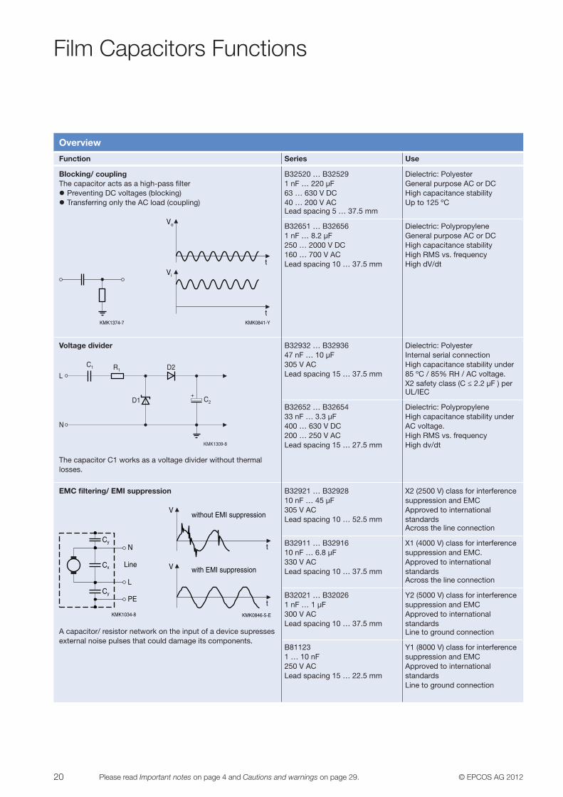
Overview
Function Series Use
Bypass/ decoupling/ smoothing The capacitor acts as a low-pass filterzz Preventing the transmission of AC voltages in both directionszz Suppressing fast transient changes
KMK1371-7KMK0842-7
Vo
t
t
Vi
DC link/ energy storageThe capacitor stores a charge and then releases it in a short high-energy pulse.
KMK1372-D KMK1373-R
Vo
t
t
Vi
B32520 … B325291 nF … 220 µF63 … 450 V DCLead spacing 5 … 37.5 mm
B32774 … B327781.5 … 200 µF450 … 1300 V DCLead spacing 27.5 … 52.5 mm
B32674 … B327780.47 … 60 µF450 … 1050 V DCLead spacing 27.5 … 52.5 mm
B32671Z … B32673Z0.01 … 2.2 µF450 … 630 V DCLead spacing 10 … 22.5 mm
B32671P … B32673P0.068 … 2.2 µF450 … 630 V DCLead spacing 10 … 22.5 mm
Dielectric: PolyesterLow voltage applicationsUp to +125 ºC4 pin upon request
Dielectric: PolypropyleneHigh density of cap per volumeUp to +105 ºC2 and 4 pin versions
Dielectric: PolypropyleneHigh IRMS vs. frequencyUp to +105 ºC2 and 4 pin versions
Dielectric: PolypropyleneHigh AC voltage capabilityUp to +125 ºCFor PFC modules
Dielectric: PolypropyleneUp to +125 ºCFor PFC modules
Snubbering/ resonantCS (Snubber): Capacitor protects semiconductors from overvoltages by high current switching.CR (Resonant): LC system oscillates at a specific frequency.
KMK1311-Z
CS CR
KMK1310-6
t
V AC
KMK0810-4
CS
KMK0849-U
t
Vsn
B32651 … B326561 nF … 8.2 µF250 … 2000 V DCLead spacing 10 … 37.5 mm
B32671L … B32672L1 nF … 1 µF160 … 900 V ACLead spacing 10 … 37.5 mm
B32632 … B326340.47 … 330 nF630 … 3000 V DCLead spacing 15 … 27.5 mm
B32686 22 … 680 nF1000 … 2000 V DCLead spacing 37.5 mm
Dielectric: PolypropyleneHigh RMS vs. frequency2 pin and strap terminals4 pin upon request
Dielectric: PolypropyleneMiniaturizedUp to +125 ºCHigh AC voltage capabilityHigh IRMS vs. frequencyHigh dV/dt
Dielectric: PolypropyleneMetal foil technology (MFP)Very high dv/dtPowder-dipped
Dielectric: PolypropyleneMetal foil technology (MFP)Very high dv/dt 2 pin and strap terminals
Film Capacitors Functions
20 © EPCOS AG 2012Please read Important notes on page 4 and Cautions and warnings on page 29.
Overview
Function Series Use
Blocking/ couplingThe capacitor acts as a high-pass filterzz Preventing DC voltages (blocking)zz Transferring only the AC load (coupling)
KMK1374-7
t
Vo
Vi
tKMK0841-Y
B32520 … B325291 nF … 220 µF63 … 630 V DC40 … 200 V ACLead spacing 5 … 37.5 mm
B32651 … B326561 nF … 8.2 µF250 … 2000 V DC160 … 700 V ACLead spacing 10 … 37.5 mm
Dielectric: PolyesterGeneral purpose AC or DCHigh capacitance stability Up to 125 ºC
Dielectric: PolypropyleneGeneral purpose AC or DCHigh capacitance stability High RMS vs. frequencyHigh dV/dt
Voltage divider
KMK1309-8
+
LR1
C2
D2
D1
N
C1
The capacitor C1 works as a voltage divider without thermal losses.
B32932 … B3293647 nF … 10 µF305 V ACLead spacing 15 … 37.5 mm
B32652 … B3265433 nF … 3.3 µF400 … 630 V DC 200 … 250 V ACLead spacing 15 … 27.5 mm
Dielectric: PolyesterInternal serial connectionHigh capacitance stability under 85 ºC / 85% RH / AC voltage.X2 safety class (C ≤ 2.2 µF ) perUL/IEC
Dielectric: PolypropyleneHigh capacitance stability under AC voltage.High RMS vs. frequencyHigh dv/dt
EMC filtering/ EMI suppression
KMK1034-8
Cy
Cx
Cy
N
L
PE
Line
KMK0846-5-E
V
t
t
V
without EMI suppression
with EMI suppression
A capacitor/ resistor network on the input of a device supresses external noise pulses that could damage its components.
B32921 … B32928 10 nF … 45 µF305 V ACLead spacing 10 … 52.5 mm
B32911 … B3291610 nF … 6.8 µF330 V ACLead spacing 10 … 37.5 mm
B32021 … B320261 nF … 1 µF300 V ACLead spacing 10 … 37.5 mm
B811231 … 10 nF250 V ACLead spacing 15 … 22.5 mm
X2 (2500 V) class for interference suppression and EMCApproved to internationalstandardsAcross the line connection
X1 (4000 V) class for interferencesuppression and EMC. Approved to international standardsAcross the line connection
Y2 (5000 V) class for interferencesuppression and EMCApproved to internationalstandardsLine to ground connection
Y1 (8000 V) class for interferencesuppression and EMCApproved to internationalstandardsLine to ground connection
Film Capacitors Functions

21© EPCOS AG 2012 Please read Important notes on page 4 and Cautions and warnings on page 29.
Overview
Function Series Use
Output filtering at AC operationThe capacitor under AC voltage operation acts as a low-pass filter, attenuating the higher frequency harmonics.
KMK1376-T
Vi
Vo
0 0.01 0.02 0.03 0.04
0 0.01 0.02 0.03 0.04
KMK1375-4
B32794 … B327980.82 … 75 µF250 … 400 V ACLead spacing 27.5 … 52.5 mm
B32651 … B326561 nF … 8.2 µF250 … 2000 V DC160 … 700 V ACLead spacing 10 … 37.5 mm
Dielectric: PolypropyleneOptimized AC voltage with small dimensionsHigh IRMS vs. frequencyUp to 105 ºC2 and 4 pin versions
Dielectric: PolypropyleneGeneral purpose AC or DCHigh capacitance stability High RMS vs. frequencyHigh dv/dt
Flexibility as a broadliner: Not all the product range and encapsulation options are shown in the above table: Naked (B3256*), powder-dipped (B3261*, B3251*) and axial versions (B32669, B32231, B32232) of these products can be found on www.epcos.com as well as the Film Capacitors Data Book.
Film Capacitors Functions

22 © EPCOS AG 2012Please read Important notes on page 4 and Cautions and warnings on page 29.
General Technical Information
Self healingThe most important reliability feature of film capacitors is their self-healing capability, i.e. their ability to clear faults (such as pores or impurities in the film) under the influence of a high voltage.
x
r1 10
4 2
42
6
6
8 10 1
2 4
245
5
10 101
1
399 7
37 9
KMK1377-M-E
1 Dielectric2 Metalized electrodes3 Material displacing shock wave4 Air gap with metal vapor5 Plasma zone6 Plasma zone
7 Boundary layer between gas phase dielectric and plasma 8 Breakdown channel 9 Gas phase dielectric10 Zone of displaced metalization and dielectric (isolating region)
The metal coatings, vacuum-deposited directly onto the plastic film, are only 20 ... 50 nm thick. If the dielectric breakdown field strength is exceeded locally at a weak point, a dielectric breakdown occurs. The high tempera-tures reached in the breakdown channel (up to 6000 K) transform the dielectric into a highly compressed plasma that forces its way out. The thin metal coating in the vicinity of the channel is totally evaporated by interaction with the plasma so that it escapes from the breakdown channel. The rapid expansion of the plasma causes it to cool after a few microseconds, thus quenching the discharge before a greater voltage drop takes place. The insulated region re-sulting around the former faulty area will cause the capaci-tor to regain its full operational ability.
It should be noted that the voltage levels needed to ac-tivate the self-healing mechanism are far above nominal voltages: this is a safety feature designed to act when the capacitors are operated out of their rated conditions.
Thermal analysisThe ability of a capacitor to withstand a continuous (sinu-soidal) alternating voltage VRMS or alternating current IRMS is a function of the frequency and is limited by different factors. Across the whole frequency range, three regions can be identified in terms of the limiting factor for the VRMS voltage level admissible for the capacitor: they go from a regime where the voltage is limited by the corona dis-charge (A) to a range where it is limited by the peak current admissible for the contacting part of the capacitor (C).In between, there is a wide range of frequencies in which the maximum permissible voltage (i.e. current) is limited by the maximum admissible self-heating of the capacitor (B).
KMK1378-N-E
Voltage limitedby coronadischarge
a b c
1~f f
. 4
V ACA
ltern
atin
g vo
ltage
Frequencyf
Volta
ge
Cur
rent
fFrequency
Alte
rnat
ing
curr
ent
ba c
Limited bythermal power
dissipationtan δ
VRMS
VRMS = constant V
RMS
~V
RMS
f1
IRMS
VRMS =IRMS
C 2πf.
IRMS = VRMS · C · 2πf
f1 f2
IRMS = constant Ic
I RMS
~ f
Currentlimited bycontacts
4fIRMS ~
f1 f2
Our area of interest is therefore region B, which is limited by thermal dissipation. This means that at any operating point (f, IRMS, sine wave) of the curve, the self-heating will be around 15 ºC. The sum of this self-heating (∆T) in the capacitor and the ambient temperature (TA) around the capacitor induced by other components will give the total temperature of the capacitor: capacitor temperature T = TA + ∆T. This temperature should be used in further calculations of the maximum operating voltage and operat-ing life.

23© EPCOS AG 2012 Please read Important notes on page 4 and Cautions and warnings on page 29.
General Technical Information
How to estimate self-heating in region A
KMK1379-1-E
fFrequency
Alte
rnat
ing
curr
ent
4f
ba c
x1
Ic
IRMS
Iref1
I1
I RMS
~ f
Currentlimited bycontacts
IRMS = constant
f1
IRMS ~
In region A, the AC voltage is limited by corona discharge, so the self-heating is negligible, especially in MKP prod-ucts. To estimate the IRMS in region (A) that would cause a self-heating of 15 °C, we could extend the curve of region (B) towards region A (red line). So the values in the figure (f1, Iref1, sinusoidal) would cause a self-heating of 15 °C. Then under I1 (sinusoidal), the expected self-heating could be estimated from:
∆T = · 15I1
Iref1
2
What to do in case of a non-sinusoidal waveform:
KMK1380-2-E
fFrequency
f1
Alte
rnat
ing
curr
ent
4f
ba
Currentlimited bycontacts
Ic
c
IRMS
IRMS ~
IRMS = constant
I RMS
~ f
Iref1
I1 x1
Iref3 Iref2
x2
x3I3
I2
f2 f3
First, it is necessary to estimate the contribution from the main harmonics by performing a Fourier decomposition. Assuming for example that three main harmonics are obtained: x1. (f1, I1) operating point, then Iref1 can be obtained from the curvex2 (f2, I2): operating point, then Iref2 can be obtained from the curvex3 (f3, I3): operating point, then Iref3 can be obtained from the curve
We know that the curve was calculated for 15 °C. The maximum self-heating of the capacitor over the ambient temperature (TA) induced by other components would be:
∆T = · 15 + · 15 + 2I1
Iref1
2I2Iref2
· 152I3
Iref3
The total self-heating (∆T) plus the ambient temperature (TA) result in the capacitor temperature, which must be lower than the maximum operating temperature stated in the corresponding data sheet.
In any case, a real test using thermocouples on the surface of the capacitor is strongly recommended. The thermocou-ples should be placed on the center of the case surface, as shown in the following figure (an unconnected dummy capacitor is used to estimate TA):
KMK0812-K-E
approx. 50 mm
Capacitorunder test
PC board
Dummycapacitor
(not connected)
Example of the maximum permissible VRMS vs. frequency f for a sinusoidal waveform.
Figure below shows that a 220 nF capacitor has a maxi-mum VRMS of 100 V at 20 kHz. So under these conditions (100 VRMS, 20 kHz) the self-heating (∆T) will be 15 °C.Let us now calculate the maximum IRMS at this frequency:IRMS = VRMS · 2pf · C = 100 · 2p · 20000 · 220 · 10-9 = 2.765 A
KMK1076-9
Hz10310
50
100
1000
104 105 106
f
V ACVRMS
33 nF68 nF150 nF220 nF

24 © EPCOS AG 2012Please read Important notes on page 4 and Cautions and warnings on page 29.
For intermediate values of capacitance not included in the graphs, for example C’ = 200 nF, the permissible RMS voltage or current can be approximately calculated from the closest existing curves according to:
V’RMS = VRMS · = 100 · = 104.8 VCC’
220200
I’RMS = IRMS · = 2.765 · = 2.636 AC’C
200220
Sometimes it is necessary to estimate the self-heating ∆T’ for a given VRMS (i.e. 75 V) and frequency (i.e. 20 kHz). From each curve in the corresponding data sheet we can obtain the maximum permissible VRMS,max at the required frequency. In this example, it is 100 V at 20 kHz. The fol-lowing equation is applied:
∆TV’,f = · ∆TV,f = · 15 = 8.4 °C 2V’RMS
VRMS,max.
275
100
Reliability and life expectancyThe reliability of our capacitors is given by their prob-ability to perform satisfactorily for a given period of time while operating under specified conditions. Two significant statistical parameters are specified for the reliability of our products: Failure rate (l) and service life (tsl).
Our product series are characterized in terms both reliabil-ity parameters, with data obtained from life and endurance tests. We usually provide the failure rate referenced to the standard conditions, and the service life referred to nominal conditions. These values can be found in the data sheet for the specific product.
Both service life and failure rate can be extrapolated to different conditions, taking into account the appropriate correction factors:
λ = λref · πV · πT tsl = tsl,ref · πV
1πT
1·
For this calculation, the standard factors of the IEC 1709 should be applied:
T (ºC) pT T (ºC) pT V / VR pV
≤ 40 1 110 77 10% 0.2650 1.8 120 206 25% 0.4255 2.3 125 346 50% 1.0060 3.1 60% 1.4270 5.2 70% 2.0480 9 80% 2.9385 12 90% 4.2290 16 100% 6.09100 33 110% 9.00105 50 120% 13.00
Where T is the temperature of the capacitor, V is its voltage, and VR its rated voltage.
Example:Suppose that we need to know the service life of a product when it operates at +85 °C and rated voltage. According to the product data sheet, its service life is 200,000 h at +40 °C and rated voltage:
t
40°C,VR = 200,000 hsl
We therefore need the conversion factor from the reference temperature of +40 °C to +85 °C. We get this from the previous table:
π 85°C = 12T
With this, and using the formula above, we can estimate the service life of the capacitor at +85 °C and nominal volt-age as follows:
= 200,000 · = 16,666.67 h 1211
Tπ
85°Ct
85°C,VR = t
85°C,VR · sl sl
If we wanted to estimate its service life at a continu-ous voltage and temperature differing from the reference values, we would need an additional factor for the voltage. Suppose we now want to estimate the service life of the same capacitor for continuous operation at +85 °C and 90% of the rated voltage. Then we should use two factors:
For temperature:
For voltage:
General Technical Information
π 85°C = 12T
= = 0.693 6.094.22π
90% = π V
π90%VR
VR

25© EPCOS AG 2012 Please read Important notes on page 4 and Cautions and warnings on page 29.
And with this, again applying the above formula:
· = 24,052.13 h = 200,000 · 121
0.69311
Tπ
85°CVR
1π
90%t
85°C,VR = t
85°C,VR · sl sl ·
And here we see that reducing the continuous applied volt-age to this capacitor in this case increases its service life by more than 44%.
Additional details on reliability can be found in chapter Reliability of our Film Capacitors Data Book.
Thermal stability and reliabilityThermal stability, efficiency and reliability are key require-ments for modern industrial designs that are now perfectly fulfilled by film capacitors. The stability of their electrical properties is decisive when deciding on the capacitance to be used in the final design. In many cases and industrial applications, stability is the reason for over-dimensioning the capacitor bank.
15 40 65 90 11575%
85%
95%
105%
115%
60_ 35_ 10_
FilmOther
Temperature [°C]
KMK1381-B-E
For MKP film capacitors, the capacitance change remains within ±5% across a wide range of temperatures from -50 ºC to +105 ºC, four times lower than the typical drift allowed to alternative capacitor technologies, whose tem-perature operating window is even narrower. There is also no voltage influence on the capacitance value.
040
1
2
3
4
5
55 70 85 100 115Continuous operating temperature [°C]
t sl _
(MK
P) /
t sl _
(oth
er)
KMK1382-0-E
Product reliability is a major concern for designers of state-of-the-art industrial applications. EPCOS offers a wide range of highly reliable series of film capacitors with service lives well above that offered by other technologies. This su-perior performance of EPCOS film technology is consistent across a wide range of application temperatures.
General Technical Information

26 © EPCOS AG 2012Please read Important notes on page 4 and Cautions and warnings on page 29.
Quick Guide to Operating Conditions vs. Technical Parameters
The example shown below serves as a guide for selecting the appropriate capacitor on the basis of the operational parameters:
Inputs required zz Capacitancezz V, I waveformszz Ambient temperature around the capacitor TA or in case of real testing, capacitor temperature T measured on case (see chapter Thermal Analysis).
VO-P max.VPP max.
00
0.005 0.01 0.015 0.02 0.025 0.03
50
100
150
200
250
300
350
400VRMS @ Highrequency
KMK1383-8-E
Basic selection criteriaSelection of capacitor to comply with data sheet param-eters: zz Vop,max ≤ VR,DC
zz Vpp,max ≤ 2 · 1,41 · VRMS zz TA ≤ Tmax
Thermal analysisThermal analysis or estimation of capacitor temperature: Calculation of main harmonics VRMS or IRMS at every fre-quency. Estimate the self-heating ∆T (following the indica-tions given in chapter Thermal Analysis). The temperature measured on the capacitor will be: T = TA+∆T
KMK1384-6-E
0.002 0.003 0.004 0.005 0.006 0.007 0.008
200
600
1000
200
600
1000
0.001
VPP max. for AC waveform
_
_
_
DeratingThe operating voltage may need to be derated as a func-tion of the capacitor temperature T by applying the derat-ing factor given in the specific data sheet:. Alternatively, a new capacitor with higher VR may be choosed, thus allow-ing a higher operating voltage.
For example, for a MKP capacitor VR = 800 V DC whose derating starts at 85 ºC as shown in figure below:
T55
KMK0800-W
85 °C
1.0VR
VC
0.7VR
40 150110 125
0.5VR
100
PEN
PP
PET
_ _
0.8VR
zz If the temperature of the capacitor T is +70 ºC and the maximum expected operating voltage Vo-p = 800 V, the capacitor selection is correct.zz If the capacitor temperature is +100 ºC and maximum Vop = 800 V, then the maximum voltage of the application shall be limited to 0.8 · 800 V = 640 V
A capacitor with VR = 1000 V DC should be selected to allow 800 V at 100 ºC.
Peak currentMaximum peak current (A) = C (µF) · dV/dt (V/µs). dV/dt values and the pulse characteristic K0 are given in every product data sheet. K0 provides the reference to evaluate the heat energy generated by a pulse. These dV/dt and K0 parameters are valid for isolated pulses, i.e. the heat energy (Q) of one pulse is dissipated completely before a second pulse is received.
If a train of pulses is applied, this criterion alone is not applicable and a thermal analysis should be performed as described in section “Thermal Analysis”.

27© EPCOS AG 2012 Please read Important notes on page 4 and Cautions and warnings on page 29.
Technical Parameters
Rated capacitance CR
The capacitance measured at 1 V AC and 1 kHz under standard ambient conditions (in accordance with IEC 60068-1, sub-clause 5.2). This value is normally marked on the product.
Capacitance toleranceDefined as the permissible relative deviation of the capaci-tance from the rated value: it is expressed as a percentage of the nominal value. The capacitance should be measured at a temperature of +20 °C, 1 V AC and 1 kHz.
Capacitance driftCapacitance is subject to both irreversible and reversible changes. The capacitance drift is the sum of all time-dependent irreversible changes of capacitance during its service life. This variation is stated as a percentage of the capacitance value at delivery. The typical figure is ± 5%.
Dissipation factor tan δAlso referred to as the loss factor or tan d It is the ratio between the effective power (power dissipation) and the reactive power for a sinusoidal load of specified frequency, expressed in per cent.
LS ESR CI
+ _+ _ + _+ _VL VESR VC
+ VKMK0793-A
KMK0794-I
δ
θ
V
I2πf · C
VESR = I · ESR
VC =
Given the angle d above, the tan d can be calculated as follows:
tan δ = ESR · 2πf · C
Equivalent Series Resistance ESRThe ESR represents the global ohmic resistance associat-ed with a capacitor. It comprises not only the resistance of the contacts (Rs), but any other phenomena which contrib-ute their resistance, such as the dielectric polarization and leakage (parallel resistance Rp), already described for the dissipation factor.
From the definition of tan d, the ESR can be expressed as:
ESR =2πfCtan δ
The ESR depends not only on the dielectric characteristics but also on design parameters, and varies considerably depending on the series.
ESR CI
+ _ + _+ _VESR VC
KMK1385-4
The ESR is important because it determines the power dissipation of the capacitor and thus its self-heating. For frequencies well below the natural resonance frequency, the equivalent circuit diagram of the capacitor can be sim-plified to a series connection of the capacitance C and the equivalent series resistance (ESR)
Here the power dissipation is a function of the voltage VESR across the equivalent series resistance (ESR), or the cur-rent I through it, and is expressed by:
= ESR · I2P =ESRVESR
2
Since
VESR2 =
1(2πfC)2
ESR2 +
ESR2 · V2
And since for film capacitors tan d = 2pfC · ESR << 0.1
VESR2 = ESR2 · (2πfC)2 · V2
The power can be expressed as
P = 2πfC · tan δ · V2
28 © EPCOS AG 2012Please read Important notes on page 4 and Cautions and warnings on page 29.
Technical Parameters
Insulation resistance Rins
The insulation resistance Rins of a capacitor is a measure of its resistance in DC operation. Under a stationary DC voltage, a leakage current flows through the dielectric and over the capacitor surfaces. Rins is measured by determining the ratio of the applied DC voltage to the resulting leakage current flowing through the capacitor, once the initial charging current has ceased (typically, after a period of 1 min ± 5 s).
The measuring voltage depends on the rated voltage and is specified in Section 4.5.2. of IEC 60384-1:
Rated voltage VR of capacitor Measuring voltage
10 V ≤ VR < 100 V (10 ± 1) V
100 V ≤ VR < 500 V (100 ± 15) V
500 V ≤ VR (500 ± 50) V
Pulse handling capability dV/dt, K0
The pulse handling capability of our capacitors is char-acterized by their maximum dV/dt and the parameter K0. The maximum permissible dV/dt defines the ability of a capacitor to withstand high current peaks due to fast voltage changes. The peak current is the product of the capacitance (in µF) and the dV/dt (in V/µs). The charac-teristic factor of a pulse waveform, K0, provides its energy content. The maximum permissible K0 defines the ability of a capacitor to withstand pulses involving several current peaks.
These dV/dt and K0 parameters are valid for isolated pulses, i.e. the heat energy (Q) of one pulse is dissipated completely before a second pulse is received.
If a train of pulses is applied, this parameter is not sufficient and a thermal analysis should be performed.
Rated voltage VR
This is the maximum voltage which may be continuously applied to a capacitor at any ambient temperature below the rated temperature.
Category voltage VC
This is the maximum voltage (expressed as a fraction of the rated voltage) which may be continuously applied to a capacitor at any ambient temperature within a range of category temperatures.
Ambient temperature Ta
The ambient temperature is the temperature of the air sur-rounding the component.
Rated temperature TR
This is the maximum temperature at which the rated volt-age can be applied continuously. For higher temperatures (up to the upper category temperature), voltage derating needs to be applied.
Category temperature rangeThe range of temperatures at which a capacitor can oper-ate continuously is usually called the category temperature range. The limit temperatures (upper and lower category temperatures) are defined in the climatic category, which is a numerical code specifying the limits of the category temperature range and the duration of a specified humidity test (in accordance with IEC 60068-1, Appendix A).
Maximum root mean square current / voltage IRMS / VRMS
This is the maximum RMS current (IRMS) / voltage (VRMS) admissible for the capacitor for continuous operation, as-suming a sinusoidal waveform.
Maximum peak current iPThis is the maximum current amplitude (iP) which occurs instantaneously during continuous operation. The maxi-mum peak current and the maximum rate of voltage rise (dV/dt)max of a capacitor are related as iP (A) = C (µF) ∙ dV/dtmax (V/µs).

29Please read Important notes on page 4.© EPCOS AG 2012
Cautions and Warnings
GeneralSee ”Important notes” on page 4.
Storagezz Store capacitors in original packaging only. Do not open the package prior to storage.zz Storage conditions in original packaging: storage temperature –25 °C … +40 °C, relative humidity 75% annual mean, maximum 80%, dew precipitation is inadmissible.zz Do not store capacitors where they are exposed to heat or direct sunlight. Otherwise, the packing material may be deformed or components may stick together, causing problems during mounting. zz Avoid contamination of capacitor surface during storage, handling and processing.zz Avoid storage of capacitors in harmful environments like corrosive gases (SOx, Cl etc.)zz Use the components as soon as possible after opening the factory seals, i.e. the polyvinyl-sealed packages.zz Solder capacitors within the time specified after shipment from EPCOS. For leaded components this is 24 months.
Handlingzz Capacitors must not be dropped. Chip-offs or any other damage must not be caused during handling of capacitors. zz Do not touch components with bare hands. Gloves are recommended.zz Avoid contamination of capacitor surface during handling.
Solderingzz Use resin-type flux or non-activated flux.zz Insufficient preheating may cause ceramic cracks.zz Rapid cooling by dipping in solvent is not recommended.zz Complete removal of flux is recommended.
Mountingzz Ensure that no thermo-mechanical stress occurs due to production processes (curing or overmolding processes) when capacitors are sealed, potted or overmolded or during their subsequent operation. The maximum temperature of the capacitor must not be exceeded. Ensure that the materials used (sealing/ potting compound and plastic material) are chemically neutral.zz Electrodes/ contacts must not be scratched or damaged before/ during/ after the mounting process.zz Contacts and housing used for assembly with the capacitor must be clean before mounting.
zz Ensure that adjacent materials are designed for operation at temperatures comparable to the surface temperature of the capacitor. Be sure that surrounding parts and materials can withstand the temperature.zz Avoid contamination of the capacitor surface during processing.zz The connections of sensors (e.g. cable end, wire end, plug terminal) may only be exposed to an environment with normal atmospheric conditions. zz Tensile forces on cables or leads must be avoided during mounting and operation.zz Bending or twisting of cables or leads directly on the capacitor body is not permissible.zz Avoid using chemical substances as mounting aids. It must be ensured that no water or other liquids enter the capacitors (e.g. through plug terminals). In particular, water based substances (e.g. soap suds) must not be used as mounting aids for sensors.
Operationzz Use capacitors only within the specified operating temperature range.zz Use capacitors only within the specified power range.zz Environmental conditions must not harm the capacitors. Only use the capacitors under normal atmospheric conditions or within the specified conditions.zz Contact of capacitors with any liquids and solvents should be prevented. It must be ensured that no water enters the capacitors (e.g. through plug terminals). For measurement purposes (checking the specified resistance vs. temperature), the component must not be immersed in water but in suitable liquids (e.g. Galden).zz Avoid dewing and condensation unless capacitor is specified for these conditions.zz Bending or twisting of lead wires is not permissible during operation of the capacitor in the application.zz Be sure to provide an appropriate fail-safe function to prevent secondary product damage caused by malfunction.
Effect of humidity on capacitance stabilityzz Long contact of a film capacitor with humidity can produce irreversible effects. Direct contact with liquid water or excess exposure to high ambient humidity or dew will eventually remove the film metallization and thus destroy the capacitor. Plastic boxed capacitors must be properly tested in the final application at the worst expected conditions of temperature and humidity in order to check if any parameter drift may provoke a circuit malfunction. Additional potting or/ and metal enclosures can help to withstand severe ambient conditions.

© EPCOS AG 201230
Get in Contact
EuropeAustria, Bulgaria, Greece,MacedoniaEPCOS OHGVienna/AustriaT +43 51 70 72 56 37F +43 51 70 75 56 [email protected]
Czech RepublicEPCOS s.r.o.PragueT +420 2 33 03 22 81F +420 2 33 03 22 [email protected]
Finland, EstoniaEPCOS Nordic OYEspooT +358 9 54 80 70 00F +358 9 54 80 70 [email protected]
France, Belgium, Luxembourg,MaltaEPCOS SASPantin/FranceT +33 1 49 46 67 89F +33 1 49 46 67 [email protected]
Germany, Liechtenstein,Netherlands, SwitzerlandEPCOS AGCustomer ServiceMunich/GermanyT (D) 0180 500 33 48
(0.14 Euro/min.)(NL) +31 70 33 10 611(CH) +49 89 63 62 55 40
F +49 89 63 62 80 [email protected]
HungaryEPCOS ElektronikaiAlkatrész Kft.BudapestT +36 1 436 07 20F +36 1 436 07 [email protected]
ItalyTDK-EPC Italy S.r.l.MilanT +39 02 50 99 54 25F +39 02 50 99 54 [email protected]
Poland, Latvia, LithuaniaEPCOS Polska Sp. z o.oWarsaw/PolandT +48 22 24 60 409F +48 22 24 60 [email protected]
PortugalEPCOS 2 Portugal LDAÉvoraT +351 91 75 67 927F +351 21 49 33 [email protected]
RomaniaEPCOS Sales RepresentativeTimisoaraT +40 72 31 14 [email protected]
Russia, Belarus, Kazakhstan,Moldavia, UkraineEPCOS LLCMoscow/RussiaT +7 495 663 21 00 / [email protected]
SlovakiaEPCOS Sales RepresentativeDolný KubínT +42 1 43 5 82 36 73F +42 1 43 5 82 37 [email protected]
Slovenia, Serbia, Croatia,Bosnia & Herzegovina,MontenegroEPCOS Sales RepresentativeŠkofljica/SloveniaT +386 599 56 35 3F +386 599 56 35 [email protected]
SpainEPCOS Electronic ComponentsS.A.GetafeT +34 91 514 71 61F +34 91 514 70 [email protected]
Sweden, Iceland, Denmark,NorwayEPCOS Nordic ABKista/SwedenT +46 8 4 77 27 00F +46 8 4 77 27 [email protected]
TurkeyEPCOS AGLiaison OfficeIstanbulT +90 216 5 69 81 01F +90 216 4 64 07 [email protected]
United Kingdom, IrelandEPCOS UK Ltd.Bracknell/UKT +44 13 44 38 15 10F +44 13 44 38 15 [email protected]
AsiaAfghanistan, Iran, Iraq,Jordan, Lebanon,Pakistan, SyriaEPCOS AGLiaison OfficeIstanbul/TurkeyT +90 216 5 69 81 01F +90 216 4 64 07 [email protected]
ChinaEPCOS (China) Investment Ltd.EPCOS (Shanghai) Ltd.ShanghaiT +86 21 22 19 15 00F +86 21 22 19 15 [email protected]
Hong KongEPCOS LimitedHong KongT +852 36 69 82 00F +852 36 69 82 [email protected]
India, Bahrain, Bangladesh,Kuwait, Nepal, Oman, Qatar,Saudi Arabia, Sri Lanka,United Arab EmiratesEPCOS India Private Ltd.Bangalore/IndiaT +91 80 40 39 06 15F +91 80 40 39 06 [email protected]
IsraelNisko Projects Electronics &Communications (1999) Ltd.Tel AvivT +972 37 65 73 00F +972 37 65 73 [email protected]
JapanTDK-EPC CorporationTokyoT +81 3 52 01 72 41F +81 3 52 01 72 [email protected]
KoreaTDK-EPC Korea Co. Ltd.SeoulT +82 2 21 56 68 18F +82 2 21 56 68 [email protected]
MalaysiaEPCOS RDC SDN BHDNilaiT +60 6 79 98 168F +60 6 79 98 [email protected]
Philippinesc/o TDK Electronics PhilippinesCorporationBiñanT +63 49 541 31 41 66 30 / 31F +63 49 541 31 [email protected]
Singapore, Indonesia,Thailand, VietnamEPCOS PTE LTDSingaporeT +65 68 41 20 11F +65 67 44 69 [email protected]
TaiwanEPCOS Taiwan Co. Ltd.TaipeiT +886 2 26 55 76 76F +886 2 27 82 03 [email protected]
AmericasUSA, Canada, MexicoEPCOS, Inc.Iselin, NJ/USAT +1 732 9 06 43 00F +1 732 9 06 43 [email protected]
South AmericaEPCOS do Brasil Ltda.São Paulo/BrazilT +55 11 36 12 51 87F +55 11 36 12 51 [email protected]
AustraliaAustralia, New ZealandElectronic ComponentSolutions Pty LtdMelbourne/AustraliaT +61 3 85 61 19 99F +61 3 95 74 70 [email protected]
AfricaEgyptEPCOS AGLiaison OfficeIstanbul/TurkeyT +90 216 5 69 81 01F +90 216 4 64 07 [email protected]
Morocco, TunisiaEPCOS SASPantin/FranceT +33 1 49 46 67 89F +33 1 49 46 67 [email protected]
South AfricaElectrocomp (PTY) Ltd.SandtonT +27 11 458 90 00 32F +27 11 458 90 [email protected]
09/12
The addresses of our worldwide distributors and regional sales offices are available at www.epcos.com/sales


© EPCOS AG · A Member of TDK-EPC CorporationEdition 2012 · Ordering No. EPC:60011-7600 · Printed in Germany · PP 0912.