ep tiger moth - east r/c tiger moth i n d e x before ... tail-skid wire 1 pc 1.2-mm tail-skid wire 1...
TRANSCRIPT


EP Tiger Moth
I N D E X BEFORE ASSEMBLY --------------------------------------------------------P.1 PARTS LIST ---------------------------------------------------------P.2 ASSEMBLY ---------------------------------------------------------P.3—P.17 SAFETY PRECAUTIONS----------------------------------------------------P.18
BEFORE ASSEMBLY Read through this instruction manual before assembly , so you will have an overall idea of what to do. Check all parts. If you find any defective or missing parts, contact your local dealer. Symbols used throughout this instruction manual comprise of the following.
Apply epoxy glue Apply instant glue
(C.A.glue, super glue.)
Assemble left and right Ensure smooth non-binding sides the same way. movement while assembling
Peel off covering film on Cut off shaded portion
shaded portion Drill holes with the specified Must be purchased
Diameter (here:3mm) separately!
Warning! Do not overlook this symbol!
安全注意事项 该无线遥控模型不是玩具! ● 初玩者请在有经验者帮助下进行组装,以获得最佳性能。
● 请在远离儿童的地方进行组装!
● 使用时请保证足够安全保障!您对此须负担责任
● 即使在完成安装后,也请您随时把本说明带在身边以便随
时查询。
SAFETY PRECAUTIONS This radio control model is not a toy! ● First-time builders should seek advice from people having
building experience in order to assemble the model
correctly and to produce its performance to full extent.
● Assemble this kit only in places out of children’s reach!
● Take enough safety precautions prior to operating this
model.You are responsible for this model’s assembly and
safe operation!
● Always keep this instruction manual ready at hand for
quick reference,even after completing the assembly.
*产品变更或改进时,恕不另行通知。*SPECIFICATIONS ARE SUBJECT TO CHAGE WITHOUT NOTICE.

Parts List
Hinge 6 pcs
Carbon-fibre helm support (elevator) 2 pcs Carbon-fibre helm support (rudder) 1 pc Carbon-fibre rockerarm
(rudderservo)1 pc Stainless steel
wire clamp 12 pcs
0.8-mm wire 3 m
Helm support cartridge 4 pcs
Wire connectingrod 4 pcs
M3 claw nut 2 pcs
Aluminum wafer for tail-skid wire
1 pc
1.2-mm tail-skidwire 1 pc
M2×8 mm self-threading screw 30 pcs
Extension wire for Y type servo
1 pc
Mounting seat for underdriving gear set 1 pc
Nylon helm support 2 sets 1.2-mm aileron link wire
2 pcs Nylon screw
12 pcs Wing mountingsupport 1 set Wing connector(short) 2 pcs Wing connector(long) 2 pcs Nylon fastening
4 pcs 1.8mm aluminum alloy catch 2 pcs
M3×3 mm screw 2 pcs 40-mm wheel
2 pcs Φ3 mm washer
2 pcs M3×25 mm socket head screw 2 pcs Undercarriage
1 set Φ3 mm plate washer 4 pcs

Tools Needed for Installation and Flight
Phillips head screwdriver Hex box spanner Flat blade screwdriver Modeling knife 12V battery Cutting pliers Nipper pliers
12V special charger
Scissors
4 channel or more transmitter transmitter battery Propeller 10×8, 11×4.7 Micro servo Y type wire Brushless motor
8.4V/1050 mah motor battery 4 channel or more receiver
Special governor

Assembly
------------------4pcs ------------------2pcs
3.1 Cut the reserved openings in the horizontal fin and the elevator with a modeling knife as illustrated. Insert the carbon-fibre helm supports into
the elevators and push them forward 3 mm (A). Fix them with instant glue. Insert the hinges into the horizontal fin and the elevator and fix them with instant glue. Make sure there is not any gap.
---------------------2pcs ---------------1pc
3.2 Cut a small rectangular opening (reserved) (B) at the bottom 60 mm away from the vertical fin. Insert the carbon-fibre helm support, push it forward 3 mm and fix it with instant glue. Then insert the hinges in the
corresponding position.

4.1 Install the elevators of the horizontal fin and the vertical fin as illustrated. Caution: The verticalfin must be vertical to the horizontal fin while the horizontal fin must parallel with the fuselage. The elevator tip to the central line of the fuselage is kept
at the same distance (C). Fix them with instant glue after confirmation.
a=a’’
b=b’
4.2 When the horizontal fin and the rudder of the vertical fin are assembled, each part should be rotary.

5.1 A 1.5kg.cm micro servo is required for the rudder and the elevator. The mounting position should be adjusted according to different types ofservo. The reserved opening is
22 mm long and 12 mm wide. A rubber buffer is needed when theservo is installed. The installationof rubber buffer is as illustrated (D).
5.2 The servos of both rudder and elevator are assembled as illustrated. Make sure that the output shaft of servo is towardsthe rear of fuselage.

6.1 A rectangular opening is reserved in the side of fuselage, which is the output position of the servo rockerarmof rudder. Cut off the covering film with a modeling knife. The length of the opening is cut to meet therequirements of the rudder.
----------------1pc
26.2 Place the carbon-fibre rockerarm onto the steering wheel and fix it with screws. Passthis component through the
sideboard on both sides of the fuselage and fix it onto the rudder servo. Check if
the rockerarm rubs against the sideboard of the fuselage. The opening in the sideboard needs adjusting if the rockerarm is not movable.

-----------------6pcs ----------------3m
7.1 A 0.8-mm wire is applied to the elevator and the rudder. Pass the wire through the stainless steel clamp
and the carbon-fibre helm support and again the stainless steel
clamp. Adjust the distance between the stainless steel clamp and the helm support and press the clamp with a pair of nipper pliers. Make sure that the clamp is not loose.The elevator wire extends
forward through the small holes on both sides of the fuselage while the rudder wire extends towards the front of the fuselage.
7.2 There are two slotted eyes on both sides of the central rear of the fuselage. The wire above the elevatorpasses through the upper slotted eye while the wire below the elevator through the lower slotted eye. The rudderwire extends directly towards the rockerarm of the rudder servo in the front of thefuselage.

---------------2pcs ----------2pcs ----------------2pcs
8.1 Assemble the ruderlink mechanism (E) as
illustrated and fix it onto the rockerarm of the rudder
servo. Adjust the wire. Makesure that the servo is in the central position, so is the rudder. If there is some gap, thelink can be adjusted.
--------------2pcs --------2pcs --------------2pcs
8.2 Assemble the elevator link mechanism (F) in the same way. The rockerarm in proper length should be selected (G).

------------------2pcs
9.1 The elevators are controlled by four wires,so the four wires must be fixed correctly according to the illustration. Make sure that the four wires can work at the same time.
9.2 Weigh on the elevator surface and the horizontal fin so that the elevator surface is not movable when the wire is drawn. Hold the two wires above the helm support of elevator, pass them through the stainless steel clamp (H) and pull one wire towards the elevator rockerarm. Press the
stainless steel clamp after confirmation. Pull theother towards the servo rockerarm. This wire islong enough to adjust the link, so try to move thestainless steel clamp towards the rear of thefuselage. Press the clamp with a pair of nipperpliers.

-----------------2pcs
10.1 The claw nuts are used to fix the wingas illustrated. The M3×25 mm socket head
screws are required. Fix them with epoxy glue (No glue is allowed in the thread of nut).
-----------------1pc ------------1pc ----------------2pcs
10.2 Install the 1.2-mm tail-skid wire as illustrated. Fix it with epoxy glue or instantglue.

11.1 Two openings in the back of the aileronare used to install the servos. Cut off the covering film in the corresponding position.
If any covering film crumples, iron it flat. -----------1pc
11.2 The ailerons are controlled by two
mini servos, which are connected with the Y type
extension wires. The adhesive tape is applied to the joint. The rubber
buffer is required when the servo is installed.

------------2sets ----------2pcs ----------6pcs
12.1 Install the helm support of the aileron servo as illustrated. Attention should be paid to that the helm support and the
holes for link wire must be over the rotary shaft of the aileron (K). A bit of
instant glue can be applied so that the helm support can be fixed firmly. The servo
rockerarm must be parallel to the rotary shaft of the aileron. Make
sure that the servo output is linear.
---------------6pcs
12.2 The wood blocks for fastenings are preembedded in
the upper surface of the lower wing, on which the nylon screws are fixed to connect the upper wing and the
lower wing. Turn the screws to let the teat towards the inside of the wing. Turn the two screws in the
middle to let the teat towards the outside of the wing.

---------------------2pcs ---------------------2pcs
13.1 Fix the lower wing onto the fuselage as illustrated. Check if the distance from the wing tip to the central line of fuselage is the same. Make sure that a is equal to a’’ (L). ---------------------6pcs
13.2 Fix the nylon screws on the upper wing. The method is the same with that in 12.2.

----------1set
---------------------4pcs
14.1 Install the mounting supports of the upper wing. Make sure that the supports are vertical to the wing. Fix them with epoxy glue.
-----------2pcs -----------2pcs ------------12pcs
14.2 Connect the upper wing and the lower wing. The distance
between the front support of the upper wing and the fuselage front is 43 mm (M).

15.1 A Multi-CAT brushless motor or a 540 brush motor can be applied to this model. Here is illustrated a brushless motor. In this case the wood support for motor is unnecessary and it should be cut off (N). Fix the reducing mechanism on the support with epoxy glue or instant glue. The propeller is mounted at zero degree. 15.2 The undercarriage is fixed with four special nylon fastenings. Part
------------------4pcs of the nylon fastening is cut off for future use.

16.1 Install the undercarriage beneath the fuselage as illustrated. Screw in the fixing screw and then screw it out. Apply instant glue in the tap holes. When the glue is dry,
screw in the fixing screw again so as to increase strength. Install the two wheels onto the undercarriage and fix them with the catches.
--------------------4pcs --------------------4pcs --------------------2pcs --------------------2pcs --------------------2pcs
16.2 The spinner is made of fibre glass reinforced plastics(FRP). In order to prevent the spinner from splitting, adhesive tape is required on the cut-off portion. The shadedportion in the drawing needs cutting off. (A high-speed power tool is preferable.).

--------------------4pcs
17.1 Stick with instant glue the 3-mm plate washers in the position of the fixing screws inside the FRP spinner. 。
----------------------4pcs
17.2 Fix the spinner onto the fuselage. The rear of spinner is close to the front of wing support. Move the front of spinner so that the output shaft is in the middle of the spinner. 3-mm plate washers are used in the position of the fixing screws inside the fuselage.
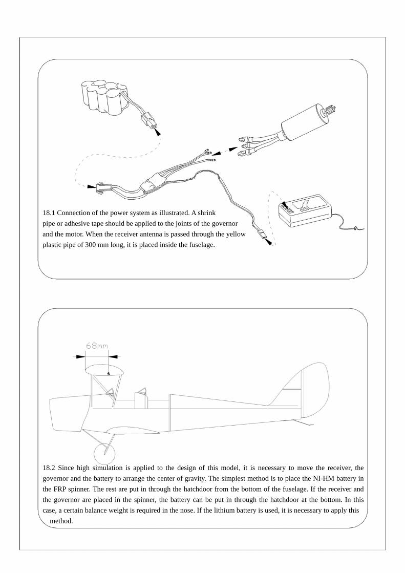
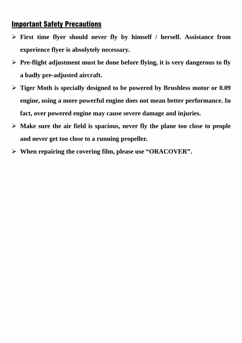
18.1 Connection of the power system as illustrated. A shrink pipe or adhesive tape should be applied to the joints of the governor and the motor. When the receiver antenna is passed through the yellow plastic pipe of 300 mm long, it is placed inside the fuselage. 18.2 Since high simulation is applied to the design of this model, it is necessary to move the receiver, thegovernor and the battery to arrange the center of gravity. The simplest method is to place the NI-HM battery inthe FRP spinner. The rest are put in through the hatchdoor from the bottom of the fuselage. If the receiver andthe governor are placed in the spinner, the battery can be put in through the hatchdoor at the bottom. In thiscase, a certain balance weight is required in the nose. If the lithium battery is used, it is necessary to apply this method.
Important Safety Precautions
First time flyer should never fly by himself / herself. Assistance from
experience flyer is absolytely necessary.
Pre-flight adjustment must be done before flying, it is very dangerous to fly
a badly pre-adjusted aircraft.
Tiger Moth is specially designed to be powered by Brushless motor or 0.09
engine, using a more powerful engine does not mean better performance. In
fact, over powered engine may cause severe damage and injuries.
Make sure the air field is spacious, never fly the plane too close to people
and never get too close to a running propeller.
When repairing the covering film, please use “ORACOVER”.