eolf-1624-15 17 29 34x series v4.b - eoptolink · eolf-1624-15 17 29 34x series ... blank=cwdm/dwdm...
TRANSCRIPT
SFF Series
Eoptolink Technology Inc., Ltd. Page 1 of 15
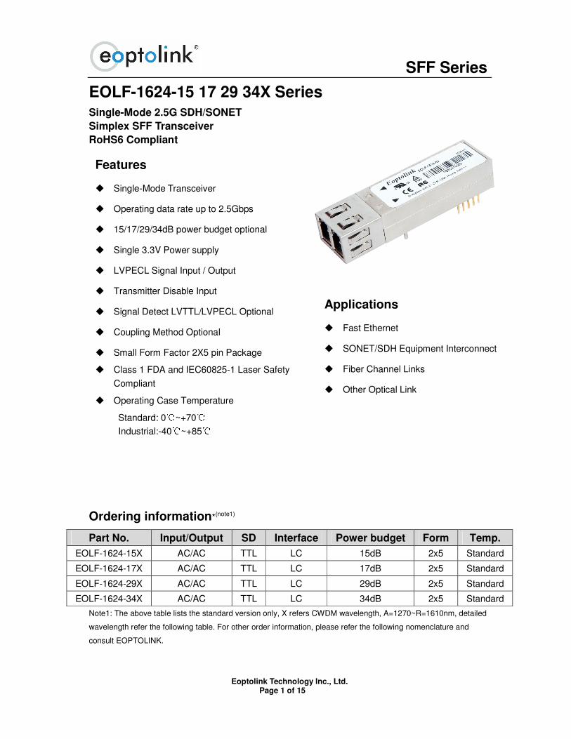
EOLF-1624-15 17 29 34X Series Single-Mode 2.5G SDH/SONET
Simplex SFF Transceiver
RoHS6 Compliant
Ordering information*(note1)
Part No. Input/Output SD Interface Power budget Form Temp.
EOLF-1624-15X AC/AC TTL LC 15dB 2x5 Standard
EOLF-1624-17X AC/AC TTL LC 17dB 2x5 Standard
EOLF-1624-29X AC/AC TTL LC 29dB 2x5 Standard
EOLF-1624-34X AC/AC TTL LC 34dB 2x5 Standard
Note1: The above table lists the standard version only, X refers CWDM wavelength, A=1270~R=1610nm, detailed
wavelength refer the following table. For other order information, please refer the following nomenclature and
consult EOPTOLINK.
Features
Single-Mode Transceiver
Operating data rate up to 2.5Gbps
15/17/29/34dB power budget optional
Single 3.3V Power supply
LVPECL Signal Input / Output
Transmitter Disable Input
Signal Detect LVTTL/LVPECL Optional
Coupling Method Optional
Small Form Factor 2X5 pin Package
Class 1 FDA and IEC60825-1 Laser Safety
Compliant
Operating Case Temperature
Standard: 0~+70
Industrial:-40~+85
Applications
Fast Ethernet
SONET/SDH Equipment Interconnect
Fiber Channel Links
Other Optical Link
SFF Series
Eoptolink Technology Inc., Ltd. Page 2 of 15
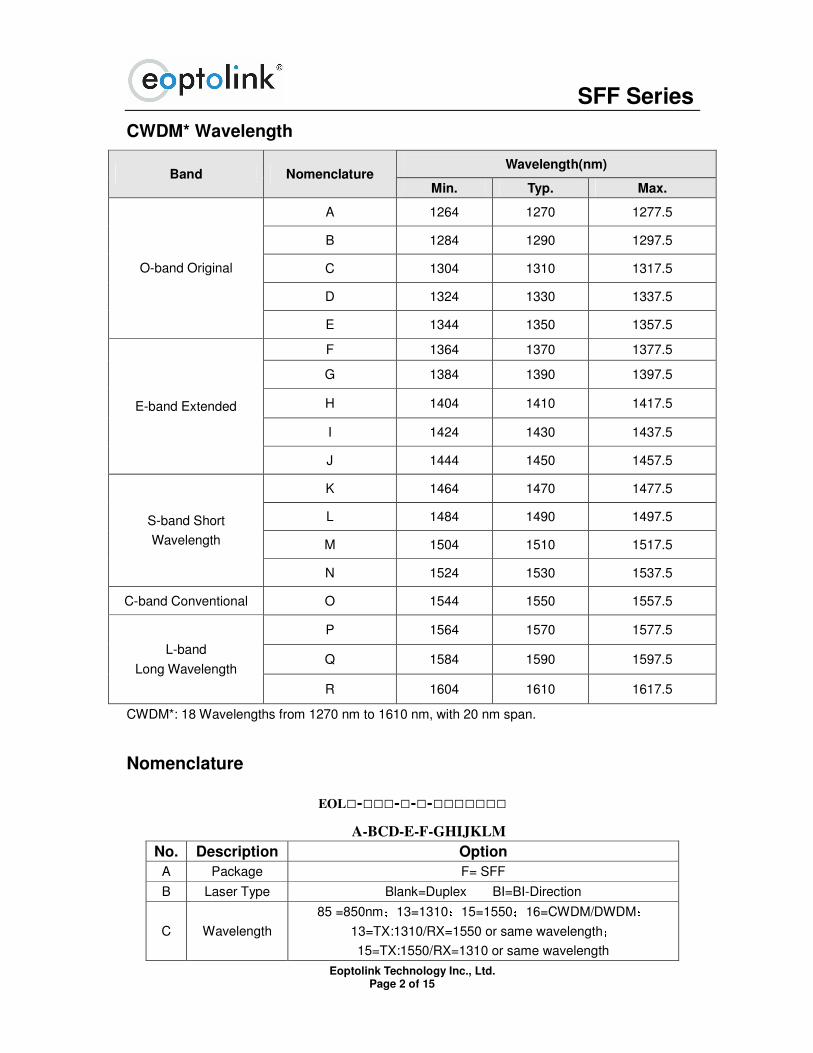
CWDM* Wavelength
Wavelength(nm) Band Nomenclature
Min. Typ. Max.
A 1264 1270 1277.5
B 1284 1290 1297.5
C 1304 1310 1317.5
D 1324 1330 1337.5
O-band Original
E 1344 1350 1357.5
F 1364 1370 1377.5
G 1384 1390 1397.5
H 1404 1410 1417.5
I 1424 1430 1437.5
E-band Extended
J 1444 1450 1457.5
K 1464 1470 1477.5
L 1484 1490 1497.5
M 1504 1510 1517.5
S-band Short
Wavelength
N 1524 1530 1537.5
C-band Conventional O 1544 1550 1557.5
P 1564 1570 1577.5
Q 1584 1590 1597.5 L-band
Long Wavelength
R 1604 1610 1617.5
CWDM*: 18 Wavelengths from 1270 nm to 1610 nm, with 20 nm span.
Nomenclature
EOL----
A-BCD-E-F-GHIJKLM
No. Description Option
A Package F= SFF
B Laser Type Blank=Duplex BI=BI-Direction
C Wavelength
85 =850nm;13=1310;15=1550;16=CWDM/DWDM;13=TX:1310/RX=1550 or same wavelength;15=TX:1550/RX=1310 or same wavelength
SFF Series
Eoptolink Technology Inc., Ltd. Page 3 of 15
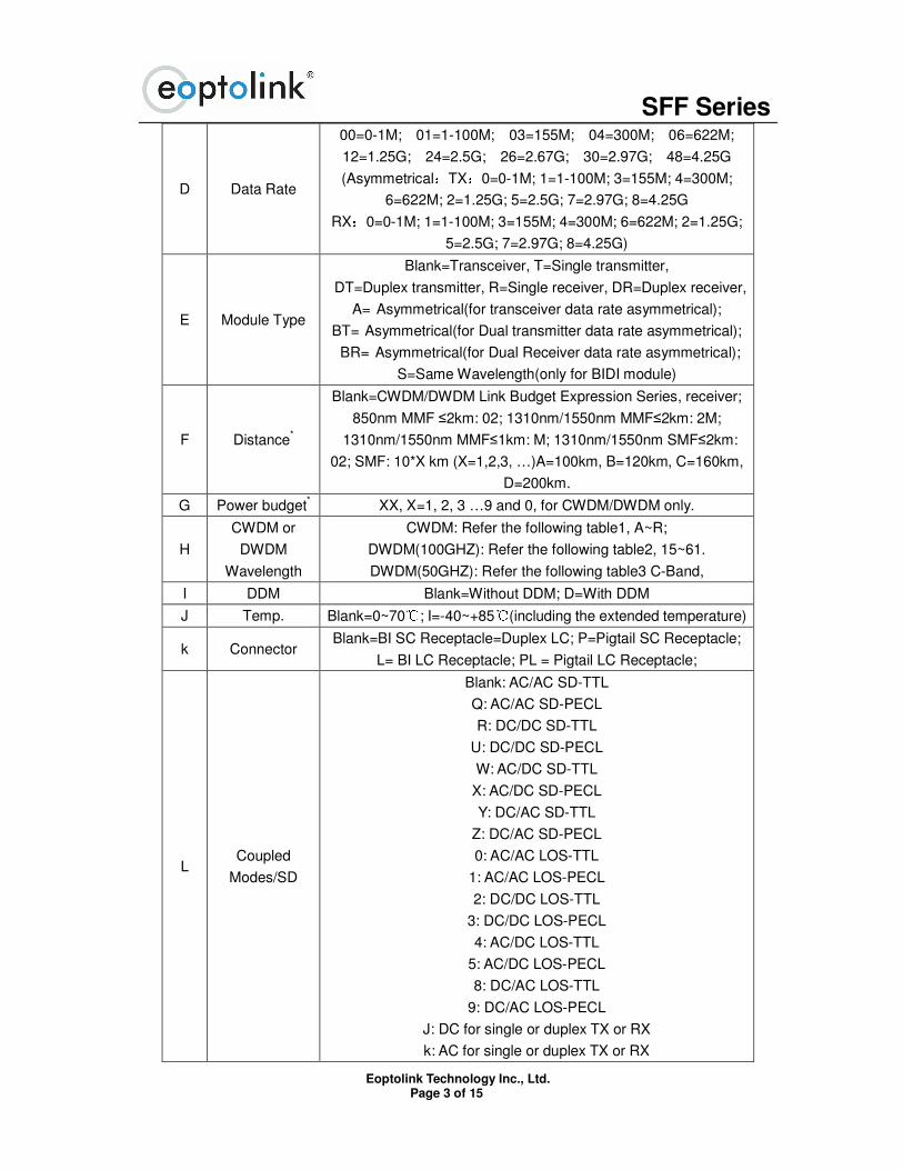
D Data Rate
00=0-1M; 01=1-100M; 03=155M; 04=300M; 06=622M;
12=1.25G; 24=2.5G; 26=2.67G; 30=2.97G; 48=4.25G
(Asymmetrical:TX:0=0-1M; 1=1-100M; 3=155M; 4=300M;
6=622M; 2=1.25G; 5=2.5G; 7=2.97G; 8=4.25G
RX:0=0-1M; 1=1-100M; 3=155M; 4=300M; 6=622M; 2=1.25G;
5=2.5G; 7=2.97G; 8=4.25G)
E Module Type
Blank=Transceiver, T=Single transmitter,
DT=Duplex transmitter, R=Single receiver, DR=Duplex receiver,
A= Asymmetrical(for transceiver data rate asymmetrical);
BT= Asymmetrical(for Dual transmitter data rate asymmetrical);
BR= Asymmetrical(for Dual Receiver data rate asymmetrical);
S=Same Wavelength(only for BIDI module)
F Distance*
Blank=CWDM/DWDM Link Budget Expression Series, receiver;
850nm MMF ≤2km: 02; 1310nm/1550nm MMF≤2km: 2M;
1310nm/1550nm MMF≤1km: M; 1310nm/1550nm SMF≤2km:
02; SMF: 10*X km (X=1,2,3, …)A=100km, B=120km, C=160km,
D=200km.
G Power budget* XX, X=1, 2, 3 …9 and 0, for CWDM/DWDM only.
H
CWDM or
DWDM
Wavelength
CWDM: Refer the following table1, A~R;
DWDM(100GHZ): Refer the following table2, 15~61.
DWDM(50GHZ): Refer the following table3 C-Band,
I DDM Blank=Without DDM; D=With DDM
J Temp. Blank=0~70; I=-40~+85(including the extended temperature)
k Connector Blank=BI SC Receptacle=Duplex LC; P=Pigtail SC Receptacle;
L= BI LC Receptacle; PL = Pigtail LC Receptacle;
L Coupled
Modes/SD
Blank: AC/AC SD-TTL
Q: AC/AC SD-PECL
R: DC/DC SD-TTL
U: DC/DC SD-PECL
W: AC/DC SD-TTL
X: AC/DC SD-PECL
Y: DC/AC SD-TTL
Z: DC/AC SD-PECL
0: AC/AC LOS-TTL
1: AC/AC LOS-PECL
2: DC/DC LOS-TTL
3: DC/DC LOS-PECL
4: AC/DC LOS-TTL
5: AC/DC LOS-PECL
8: DC/AC LOS-TTL
9: DC/AC LOS-PECL
J: DC for single or duplex TX or RX
k: AC for single or duplex TX or RX
SFF Series
Eoptolink Technology Inc., Ltd. Page 4 of 15
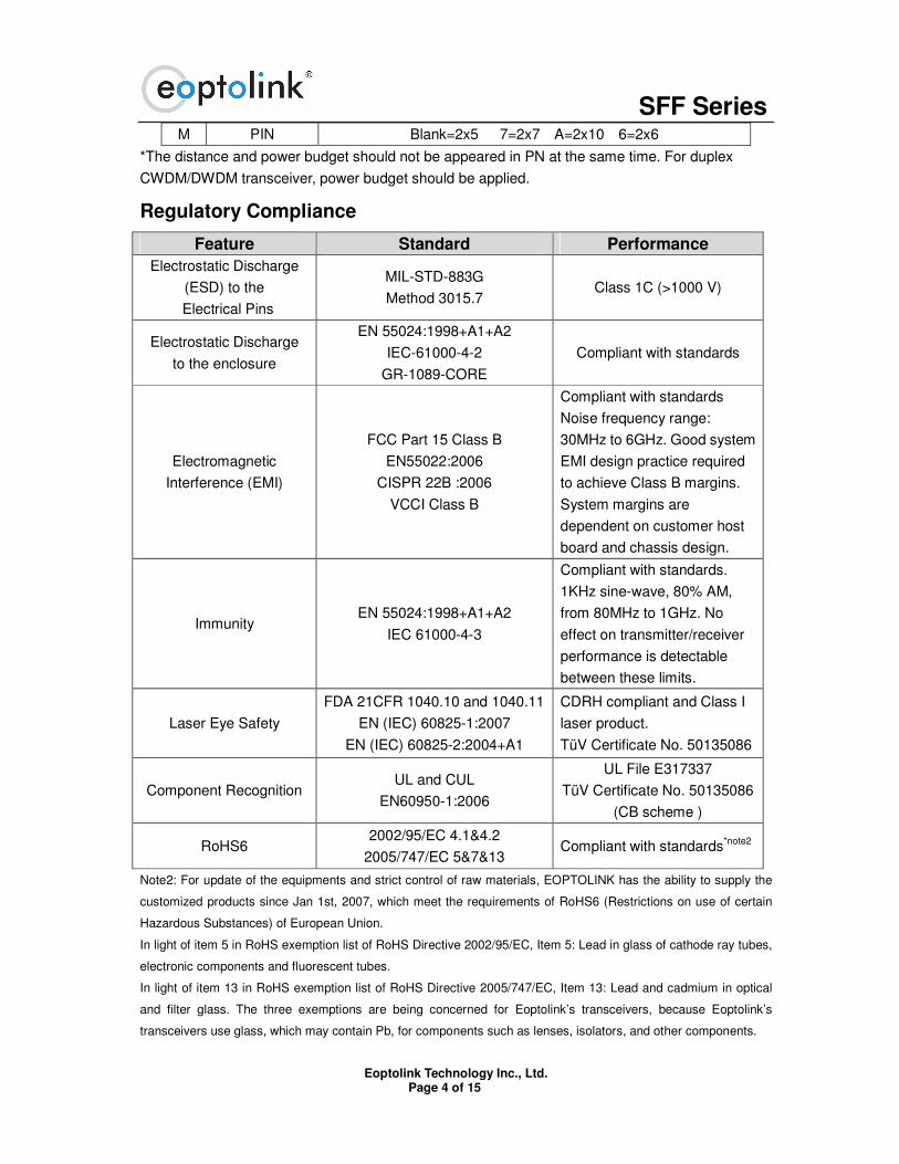
M PIN Blank=2x5 7=2x7 A=2x10 6=2x6
*The distance and power budget should not be appeared in PN at the same time. For duplex
CWDM/DWDM transceiver, power budget should be applied.
Regulatory Compliance
Feature Standard Performance
Electrostatic Discharge
(ESD) to the
Electrical Pins
MIL-STD-883G
Method 3015.7 Class 1C (>1000 V)
Electrostatic Discharge
to the enclosure
EN 55024:1998+A1+A2
IEC-61000-4-2
GR-1089-CORE
Compliant with standards
Electromagnetic
Interference (EMI)
FCC Part 15 Class B
EN55022:2006
CISPR 22B :2006
VCCI Class B
Compliant with standards
Noise frequency range:
30MHz to 6GHz. Good system
EMI design practice required
to achieve Class B margins.
System margins are
dependent on customer host
board and chassis design.
Immunity EN 55024:1998+A1+A2
IEC 61000-4-3
Compliant with standards.
1KHz sine-wave, 80% AM,
from 80MHz to 1GHz. No
effect on transmitter/receiver
performance is detectable
between these limits.
Laser Eye Safety
FDA 21CFR 1040.10 and 1040.11
EN (IEC) 60825-1:2007
EN (IEC) 60825-2:2004+A1
CDRH compliant and Class I
laser product.
TüV Certificate No. 50135086
Component Recognition UL and CUL
EN60950-1:2006
UL File E317337
TüV Certificate No. 50135086
(CB scheme )
RoHS6 2002/95/EC 4.1&4.2
2005/747/EC 5&7&13 Compliant with standards*note2
Note2: For update of the equipments and strict control of raw materials, EOPTOLINK has the ability to supply the
customized products since Jan 1st, 2007, which meet the requirements of RoHS6 (Restrictions on use of certain
Hazardous Substances) of European Union.
In light of item 5 in RoHS exemption list of RoHS Directive 2002/95/EC, Item 5: Lead in glass of cathode ray tubes,
electronic components and fluorescent tubes.
In light of item 13 in RoHS exemption list of RoHS Directive 2005/747/EC, Item 13: Lead and cadmium in optical
and filter glass. The three exemptions are being concerned for Eoptolink’s transceivers, because Eoptolink’s
transceivers use glass, which may contain Pb, for components such as lenses, isolators, and other components.
SFF Series
Eoptolink Technology Inc., Ltd. Page 5 of 15
Product Description
The EOLF-1624-XX series Single-mode transceiver is small form factor, low power, and high
performance module for bi-directional optical data communications such as SONET OC-48 / SDH
STM-16, 2XFC, Gigabit Ethernet, Fast Ethernet and SONET OC-3 / SDH STM-1. This module is
designed for single-mode fiber.
The transmitter section uses a multiple quantum well laser and is a class 1 laser compliant
according to International Safety Standard IEC-60825. The receiver section uses an integrated
InGaAs detector preamplifier (IDP) mounted in an optical header and a limiting post-amplifier IC. A
LVPECL logic interface simplifies interface to external circuitry.
Interface information
The Signal Detect (SD, active high), normal optical input of receiver represents to a logic “1” level,
which means asserted.
The following versions are available:
1. AC/AC Transceiver
Tx and Rx are AC coupling. Tx has differential 100Ω load.
2. DC/DC Transceiver
Standard PECL inputs and outputs, Tx and Rx are DC coupling.
3. AC/DC Transceiver
Tx is AC coupled, Differential 100Ω load, Rx has standard PECL output and is DC coupling.
Absolute Maximum Ratings
Parameter Symbol Min. Max. Unit
Storage Temperature Ts -40 +85 °C
Supply Voltage Vcc -0.5 3.6 V
Operating Relative Humidity - 95 %
*Exceeding any one of these values may destroy the device immediately.
Recommended Operating Conditions
Parameter Symbol Min. Typical Max. Unit
EOLF-1624-XX 0 +70 °C Operating Case
Temperature TC
EOLF-1624-XX-I -40 +85 °C
Power Supply Voltage Vcc 3.15 3.3 3.45 V
Power Supply Current Icc 300 mA
STM-16/OC-48 2.5 Gbps Date Rate
2XFC 2.125 Gbps
Performance Specifications - Electrical
Parameter Symbol Min. Typ. Max Unit Notes
SFF Series
Eoptolink Technology Inc., Ltd. Page 6 of 15
Transmitter
LVPECL
Inputs(Differential) Vin 400 2000 mVpp
AC Coupled
Inputs*(note3)
Input Impedance
(Differential) Zin 85 100 115 ohm
Rin > 100
kohm @ DC
Disable 2 Vcc+0.3 TX_Dis
Enable 0 0.8 V
Fault 2 Vcc+0.3 TX_FAULT
Normal 0 0.5 V
Receiver
LVPECL Outputs
(Differential) Vout 400 2000 mVpp
AC Coupled
Outputs*(note3)
Output Impedance
(Differential) Zout 85 100 115 ohm
Normal -1.1 -0.74 V RX_SD
SD -2.0 -1.58 V
Optical and Electrical Characteristics
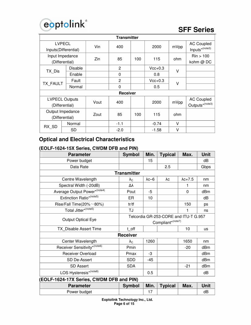
(EOLF-1624-15X Series, CWDM DFB and PIN)
Parameter Symbol Min. Typical Max. Unit
Power budget 15 dB
Data Rate 2.5 Gbps
Transmitter
Centre Wavelength λC λc–6 λc λc+7.5 nm
Spectral Width (-20dB) ∆λ 1 nm
Average Output Power*(note4)
Pout -5 0 dBm
Extinction Ratio*(note5)
ER 10 dB
Rise/Fall Time(20%~80%) tr/tf 150 ps
Total Jitter*(note5)
TJ 1 ns
Output Optical Eye Telcordia GR-253-CORE and ITU-T G.957
Compliant*(note7)
TX_Disable Assert Time t_off 10 us
Receiver
Center Wavelength λC 1260 1650 nm
Receiver Sensitivity*(note6)
Pmin -20 dBm
Receiver Overload Pmax -3 dBm
SD De-Assert SDD -45 dBm
SD Assert SDA -21 dBm
LOS Hysteresis*(note8)
0.5 dB
(EOLF-1624-17X Series, CWDM DFB and PIN)
Parameter Symbol Min. Typical Max. Unit
Power budget 17 dB
SFF Series
Eoptolink Technology Inc., Ltd. Page 7 of 15
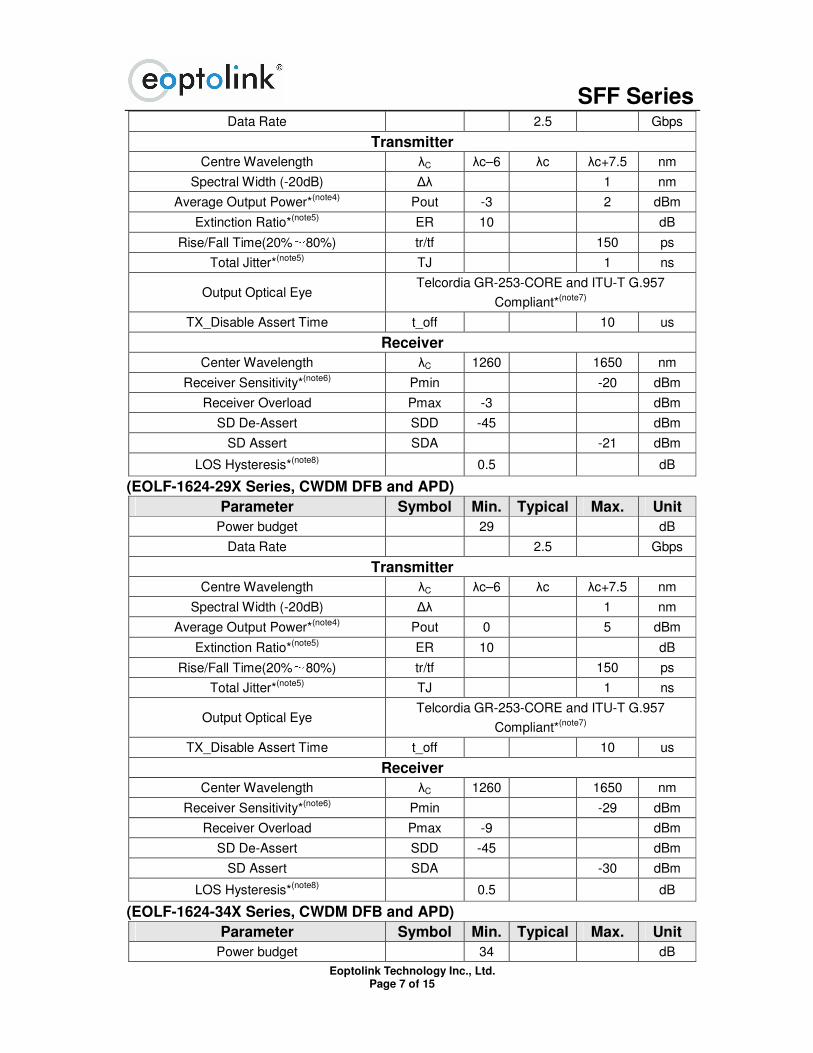
Data Rate 2.5 Gbps
Transmitter
Centre Wavelength λC λc–6 λc λc+7.5 nm
Spectral Width (-20dB) ∆λ 1 nm
Average Output Power*(note4) Pout -3 2 dBm
Extinction Ratio*(note5) ER 10 dB
Rise/Fall Time(20%~80%) tr/tf 150 ps
Total Jitter*(note5) TJ 1 ns
Output Optical Eye Telcordia GR-253-CORE and ITU-T G.957
Compliant*(note7)
TX_Disable Assert Time t_off 10 us
Receiver
Center Wavelength λC 1260 1650 nm
Receiver Sensitivity*(note6) Pmin -20 dBm
Receiver Overload Pmax -3 dBm
SD De-Assert SDD -45 dBm
SD Assert SDA -21 dBm
LOS Hysteresis*(note8) 0.5 dB
(EOLF-1624-29X Series, CWDM DFB and APD)
Parameter Symbol Min. Typical Max. Unit
Power budget 29 dB
Data Rate 2.5 Gbps
Transmitter
Centre Wavelength λC λc–6 λc λc+7.5 nm
Spectral Width (-20dB) ∆λ 1 nm
Average Output Power*(note4) Pout 0 5 dBm
Extinction Ratio*(note5) ER 10 dB
Rise/Fall Time(20%~80%) tr/tf 150 ps
Total Jitter*(note5) TJ 1 ns
Output Optical Eye Telcordia GR-253-CORE and ITU-T G.957
Compliant*(note7)
TX_Disable Assert Time t_off 10 us
Receiver
Center Wavelength λC 1260 1650 nm
Receiver Sensitivity*(note6) Pmin -29 dBm
Receiver Overload Pmax -9 dBm
SD De-Assert SDD -45 dBm
SD Assert SDA -30 dBm
LOS Hysteresis*(note8) 0.5 dB
(EOLF-1624-34X Series, CWDM DFB and APD)
Parameter Symbol Min. Typical Max. Unit
Power budget 34 dB
SFF Series
Eoptolink Technology Inc., Ltd. Page 8 of 15
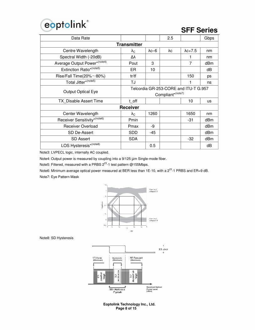
Data Rate 2.5 Gbps
Transmitter
Centre Wavelength λC λc–6 λc λc+7.5 nm
Spectral Width (-20dB) ∆λ 1 nm
Average Output Power*(note4) Pout 3 7 dBm
Extinction Ratio*(note5) ER 10 dB
Rise/Fall Time(20%~80%) tr/tf 150 ps
Total Jitter*(note5) TJ 1 ns
Output Optical Eye Telcordia GR-253-CORE and ITU-T G.957
Compliant*(note7)
TX_Disable Assert Time t_off 10 us
Receiver
Center Wavelength λC 1260 1650 nm
Receiver Sensitivity*(note6) Pmin -31 dBm
Receiver Overload Pmax -9 dBm
SD De-Assert SDD -45 dBm
SD Assert SDA -32 dBm
LOS Hysteresis*(note8) 0.5 dB
Note3: LVPECL logic, internally AC coupled.
Note4: Output power is measured by coupling into a 9/125 µm Single-mode fiber.
Note5: Filtered, measured with a PRBS 223
-1 test pattern @155Mbps.
Note6: Minimum average optical power measured at BER less than 1E-10, with a 223
-1 PRBS and ER=9 dB.
Note7: Eye Pattern Mask
Note8: SD Hysteresis
SFF Series
Eoptolink Technology Inc., Ltd. Page 9 of 15
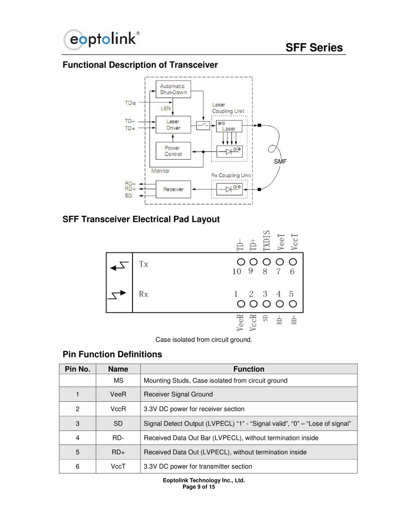
Functional Description of Transceiver
SFF Transceiver Electrical Pad Layout
Case isolated from circuit ground.
Pin Function Definitions
Pin No. Name Function
MS Mounting Studs, Case isolated from circuit ground
1 VeeR Receiver Signal Ground
2 VccR 3.3V DC power for receiver section
3 SD Signal Detect Output (LVPECL) “1” - “Signal valid”, “0” – “Lose of signal”
4 RD- Received Data Out Bar (LVPECL), without termination inside
5 RD+ Received Data Out (LVPECL), without termination inside
6 VccT 3.3V DC power for transmitter section
SFF Series
Eoptolink Technology Inc., Ltd. Page 10 of 15
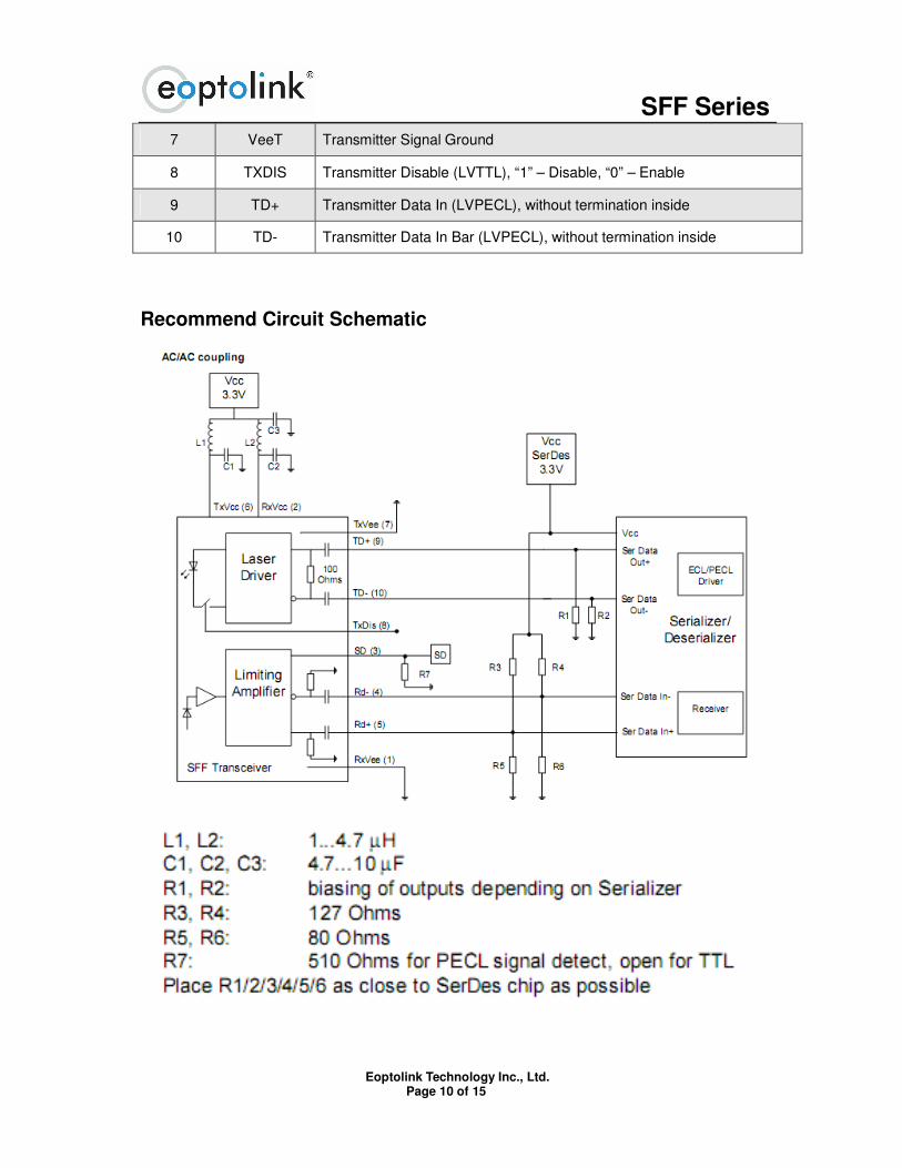
7 VeeT Transmitter Signal Ground
8 TXDIS Transmitter Disable (LVTTL), “1” – Disable, “0” – Enable
9 TD+ Transmitter Data In (LVPECL), without termination inside
10 TD- Transmitter Data In Bar (LVPECL), without termination inside
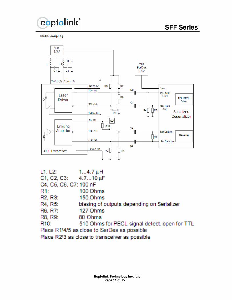
Recommend Circuit Schematic
SFF Series
Eoptolink Technology Inc., Ltd. Page 11 of 15
SFF Series
Eoptolink Technology Inc., Ltd. Page 12 of 15
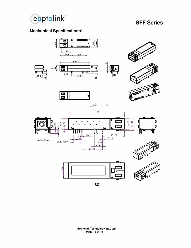
Mechanical Specifications*
SC

SFF Series
Eoptolink Technology Inc., Ltd. Page 13 of 15
Pigtail
*The pins on the three graphs are only for demonstrate, the dimension for pins is compliant to SFF
MSA.
Class 1 Labels
Laser Emission Data
Wavelength 1310nm
Total output power (as defined by FDA: 7mm aperture at 20cm distance) <0.195mW
Total output power (as defined by IEC: 7mm aperture at 10cm distance) <15.6mW
Beam divergence 12.5°
Wavelength 1550nm
Total output power (as defined by FDA: 7mm aperture at 20cm distance) <0.79mW
Total output power (as defined by IEC: 7mm aperture at 10cm distance) <10mW
Beam divergence 12.5°
SFF Series
Eoptolink Technology Inc., Ltd. Page 14 of 15
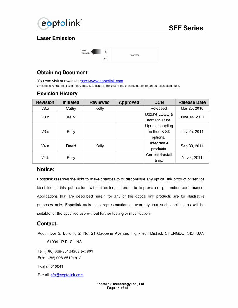
Laser Emission
Obtaining Document
You can visit our website:http://www.eoptolink.com Or contact Eoptolink Technology Inc., Ltd. listed at the end of the documentation to get the latest document.
Revision History
Revision Initiated Reviewed Approved DCN Release Date
V3.a Cathy Kelly Released. Mar 25, 2010
V3.b Kelly Update LOGO &
nomenclature. June 14, 2011
V3.c Kelly
Update coupling
method & SD
optional.
July 25, 2011
V4.a David Kelly Integrate 4
products. Sep 30, 2011
V4.b Kelly Correct rise/fall
time. Nov 4, 2011
Notice:
Eoptolink reserves the right to make changes to or discontinue any optical link product or service
identified in this publication, without notice, in order to improve design and/or performance.
Applications that are described herein for any of the optical link products are for illustrative
purposes only. Eoptolink makes no representation or warranty that such applications will be
suitable for the specified use without further testing or modification.
Contact:
Add: Floor 5, Building 2, No. 21 Gaopeng Avenue, High-Tech District, CHENGDU, SICHUAN
610041 P.R. CHINA
Tel: (+86) 028-85124308 ext 801
Fax: (+86) 028-85121912
Postal: 610041
E-mail: [email protected]

SFF Series
Eoptolink Technology Inc., Ltd. Page 15 of 15
http://www.eoptolink.com