envy gas outrigger - zippkits · envy gas outrigger a zippkits r/c boat ... slip the tub frame into...
TRANSCRIPT

1
Z I P P K I T S
Envy GAS Outrigger A Zippkits R/C Boat
Building Instructions
2015 JMP Hobby Group LLC
www.zippkits.com
Toll Free (866) 922-ZIPP

2
The Envy was developed from the JAE outrigger. The JAE series of boats were designed and
developed as a result of a joint venture between IMPBA Hall of Fame members Rod Geraghty
and Ron Zaker Jr. along with David Hall & Martin Truex Jr.
The main difference between this hull and all the others is the use of sharp edges on the bottom
of the sponsons and tub, as opposed to curved surfaces. This helps break any surface tension
of the water and makes for a faster boat.
This design approach has been built, developed and tested a great deal.
This kit represents the latest gasoline version as of December 2014. The changes we made
were many, yet the boat still looks almost exactly the same. Most of the changes were made so
that the boat was easier to build, easier to setup, handled better, was faster and easier to repair.
Many of the changes were a result of our experience, and some were the result of customer
request.
All in all, this kit is the very best we can make it, thanks to you, our customer.
The kit is not hard to assemble, as all of the hard stuff has been done for you.
That is no excuse to do a poor job with assembly. The better you build this boat, the better it will
run. Often the difference between an excellent building job and a poor one is a simple sanding
block.
A note about overhangs:
This boat is designed to shear water and prevent any capillary action of water. To do this the
tub, ski and sponsons have rear overhangs. These shear the water off and must be left in place
and not rounded in any way.
Take the time to read this entire manual, so that you are familiar with all the building
steps and their proper order. Take your time; make sure you understand everything
before you do it and you will be rewarded with an impressive running hull…
This kit is not a toy. Although R/C boating is a fun and rewarding hobby, it can be dangerous
if not done with common sense and safety in mind. Just about anyone should be able to
build this kit, but it should not be operated by children without close adult supervision.
The manufacturer assumes no liability for damages or other loss in the use of this product, as we have no control over the construction or end use of this product.

3
Tools and supplies needed to build
Sanding blocks with 80 and 150 grit paper
220, 400 and 600 grit paper
Drill with bits
Square
Flat file
FLAT Workbench
Building Jig (see below)
1/2 ounce Medium CA glue and accelerator
Good quality 30 minute epoxy
Epoxy finishing resin
Spring clamps, paper clamps, c clamps, etc.
Weights or bricks
Razor blade or X-Acto knife
Masking tape
Waxed paper
Wood filler
Primer
Paint

4
Additional items needed to complete
23-36cc water cooled Gasoline engine with 5 inch mounts (Zipp Race Pro 26cc)
.250 Collet for engine (Zipp 3440 for Zenoah, Sikk, RCMK)
.250 24 inch cable w/welded 1/4 stub shaft (Zipp 3444)
Header to fit engine (Zipp 2000 for side exhaust)
Exhaust flange (Zipp 2008)
Tuned pipe (Zipp 2011)
2 channel surface radio with 2 servos (1 quarter scale Digital 250 oz servo Hitec HS-5765MH or equivalent)
Rudder pushrod (4-40 Size) (Zipp3463)
4-40 ball link (Zipp 3457)
4-40 solder clevis (Zipp 3455)
Throttle pushrod (2-56 size) (Zipp 3462)
2-56 nylon clevis (Zipp 3459)
3 pushrod seals (Zipp 3422)
Small or Medium Fuel Cell (Zipp 3503/3504/3505/3506)
.250 strut (Zipp 3496)
.250 drive dog (Zipp 3442)
Zipp 678 or 2716 prop (starting point)
Prop nuts (Zipp 3450)
Cable grease Zip 3532)
Rudder (Zipp 3414)
36 inch length of 5/16 brass tubing (Zipp 3452)
36 inch length of 5/32 brass tubing (Zipp 3510)
All of the required hardware and accessories are available in a single Ultimate Hardware package as Zipp 3605-U.
This package contains everything except the bare engine and radio.

5
Let’s identify some of the parts so that we can easily find them when needed.
1/16 Ply parts
1/8 Ply parts
6
Foam parts
Miscellaneous parts

7
Do an inventory of all the parts, to be sure that everything is there. If anything is missing
or damaged, contact us as soon as possible, so that we can get replacements to you quickly.
Tub Jig
We recommend that you make a jig for the tub.
This can be as simple as two straight pieces of ½ to ¾ inch thick wood.
It can be as elaborate as 1/8 by 2 inch aluminum angle with adjustment slots for different tub
widths.
Either way, you need something to clamp the tub sides to.
Every critical component on this hull depends on a straight, square tub.
Do whatever it takes to get it done correctly.
The assembly order and the direction that parts must face is important.
If not assembled in the correct order, the parts will not fit.
Please take the time to read and understand every step, before you do it.
The tub bulkheads are designed to go in one way, and the bulkhead doublers (“A”) must face a
certain way.
Note that this manual contains photos of boats other than the Envy. We do this to better
illustrate the construction step.
We also do this when we forget to take certain photos, and don’t want to build another boat just
to get that pic…
8
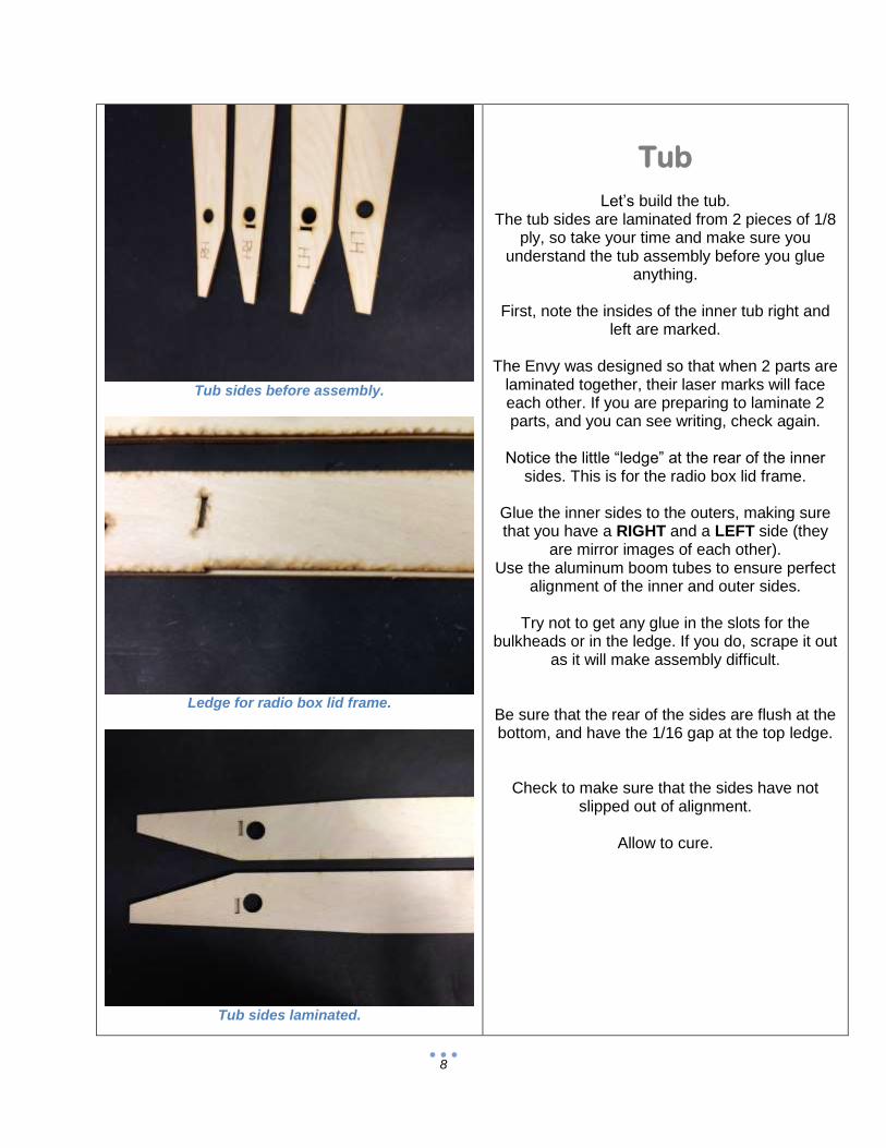
Tub sides before assembly.
Ledge for radio box lid frame.
Tub sides laminated.
Tub
Let’s build the tub. The tub sides are laminated from 2 pieces of 1/8
ply, so take your time and make sure you understand the tub assembly before you glue
anything.
First, note the insides of the inner tub right and left are marked.
The Envy was designed so that when 2 parts are
laminated together, their laser marks will face each other. If you are preparing to laminate 2 parts, and you can see writing, check again.
Notice the little “ledge” at the rear of the inner
sides. This is for the radio box lid frame.
Glue the inner sides to the outers, making sure that you have a RIGHT and a LEFT side (they
are mirror images of each other). Use the aluminum boom tubes to ensure perfect
alignment of the inner and outer sides.
Try not to get any glue in the slots for the bulkheads or in the ledge. If you do, scrape it out
as it will make assembly difficult.
Be sure that the rear of the sides are flush at the bottom, and have the 1/16 gap at the top ledge.
Check to make sure that the sides have not slipped out of alignment.
Allow to cure.

9
Use the provided square.
Be sure cooling tube hole line up.
Tub sides glued to bulkheads.
The bulkheads in the Envy are laminated from
two 1/8 inch parts.
The bulkheads are laser labeled so that the markings should face each other when
laminated. In other words, no laser writing should be visible
when the bulkheads are done correctly.
Sand the edges of all parts before gluing.
Glue bulkheads 1, 2, 3, 4 and 5 together with their respective doublers (1A, 2A, 3A, 4A and
5A). Check that all edges are flush and clamp to dry.
Make sure that all holes in the bulkheads line up
as well.
Laminate the transoms T and T together. Do not laminate TD at this time.
Once all bulkheads are laminated, check the fit of
the bulkheads in the right tub side.
Note that bulkheads 1, 2 and 3 have the doublers facing the rear, while bulkheads 4 and 5 have the
doublers facing forward.
Make sure that the rear 3 bulkheads have the 2 little holes on the right.
These are for the brass cooling water tubes installed later.
Once you are happy with the fit of the bulkheads in the tub sides, glue them in with CA or epoxy.
Use the square provided in the kit to ensure each bulkhead is perfectly square.
Add the left tub side the same way.
When cured, flip the tub over and lightly sand the
tub bottom.
10
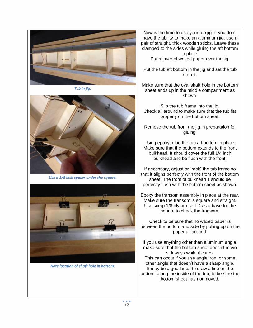
Tub in jig.
Use a 1/8 inch spacer under the square.
Note location of shaft hole in bottom.
Now is the time to use your tub jig. If you don’t have the ability to make an aluminum jig, use a
pair of straight, thick wooden sticks. Leave these clamped to the sides while gluing the aft bottom
in place. Put a layer of waxed paper over the jig.
Put the tub aft bottom in the jig and set the tub
onto it.
Make sure that the oval shaft hole in the bottom sheet ends up in the middle compartment as
shown.
Slip the tub frame into the jig. Check all around to make sure that the tub fits
properly on the bottom sheet.
Remove the tub from the jig in preparation for gluing.
Using epoxy, glue the tub aft bottom in place. Make sure that the bottom extends to the front
bulkhead. It should cover the full 1/4 inch bulkhead and be flush with the front.
If necessary, adjust or “rack” the tub frame so
that it aligns perfectly with the front of the bottom sheet. The front of bulkhead 1 should be
perfectly flush with the bottom sheet as shown.
Epoxy the transom assembly in place at the rear. Make sure the transom is square and straight. Use scrap 1/8 ply or use TD as a base for the
square to check the transom.
Check to be sure that no waxed paper is between the bottom and side by pulling up on the
paper all around.
If you use anything other than aluminum angle, make sure that the bottom sheet doesn’t move
sideways while it cures. This can occur if you use angle iron, or some other angle that doesn’t have a sharp angle. It may be a good idea to draw a line on the
bottom, along the inside of the tub, to be sure the bottom sheet has not moved.
11
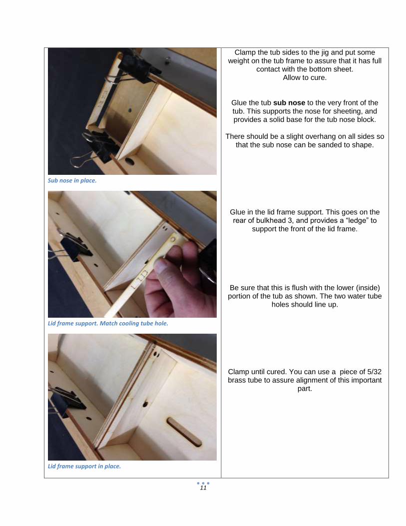
Sub nose in place.
Lid frame support. Match cooling tube hole.
Lid frame support in place.
Clamp the tub sides to the jig and put some weight on the tub frame to assure that it has full
contact with the bottom sheet. Allow to cure.
Glue the tub sub nose to the very front of the tub. This supports the nose for sheeting, and provides a solid base for the tub nose block.
There should be a slight overhang on all sides so
that the sub nose can be sanded to shape.
Glue in the lid frame support. This goes on the rear of bulkhead 3, and provides a “ledge” to
support the front of the lid frame.
Be sure that this is flush with the lower (inside) portion of the tub as shown. The two water tube
holes should line up.
Clamp until cured. You can use a piece of 5/32 brass tube to assure alignment of this important
part.

12
Transom doubler.
Transom brace. One on each side.
Lots of meat here…
Glue in the transom doubler TD. This goes in front of the transom. The cooling holes should line up.
Glue in the two transom braces in place on each side of the transom doubler.
Clamp all until cured.
You should have a nice, strong rear end at this point. Always a good thing…

13
Note that all holes align.
Aft bottom sheet sanded and ready for fwd bottom.
Fwd bottom in place. Note rear overhang.
When cured, remove the tub from the jig and flip it over.
Put the upside down tub back in the jig.
Sand the forward tub bottom so that the FWD bottom sheet will sit flat.
This will include sanding a bevel on the aft bottom to match the angle of the sides.
Glue the forward bottom sheet in place. The forward sheet should overhang on the rear.
See drawing.
When cured, sand the bottom sheets flush with the tub sides and front. Do not sand off the rear
overhang. .

14
This is what makes a JAE a JAE… Sponsons are
similar.
Bamboo skewers glued in place.
Sanded flush.
This is one of the things that make this such an efficient design. By keeping all rear breaks sharp, water is not allowed to stick, and is encouraged
to shear off cleanly, for much less drag.
Drill two 1/8 inch holes through the tub sides, into the transom. Make these about ¾ inch deep. Cut 4 pieces of bamboo skewer about an inch
long. Put a drop of glue in the hole, and hammer the
skewer in each hole until it bottoms out. Allow to cure.
Cut the skewer with side cutters and sand flush.
The transom is now permanently attached, without the need for any additional reinforcement.
15
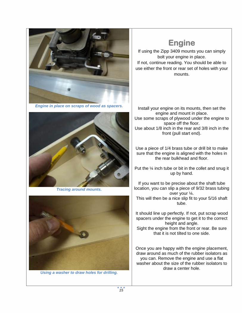
Engine in place on scraps of wood as spacers.
Tracing around mounts.
Using a washer to draw holes for drilling.
Engine If using the Zipp 3409 mounts you can simply
bolt your engine in place.
If not, continue reading. You should be able to
use either the front or rear set of holes with your
mounts.
Install your engine on its mounts, then set the
engine and mount in place. Use some scraps of plywood under the engine to
space off the floor. Use about 1/8 inch in the rear and 3/8 inch in the
front (pull start end).
Use a piece of 1/4 brass tube or drill bit to make sure that the engine is aligned with the holes in
the rear bulkhead and floor.
Put the ¼ inch tube or bit in the collet and snug it up by hand.
If you want to be precise about the shaft tube
location, you can slip a piece of 9/32 brass tubing over your ¼.
This will then be a nice slip fit to your 5/16 shaft tube.
It should line up perfectly. If not, put scrap wood spacers under the engine to get it to the correct
height and angle. Sight the engine from the front or rear. Be sure
that it is not tilted to one side.
Once you are happy with the engine placement, draw around as much of the rubber isolators as
you can. Remove the engine and use a flat washer about the size of the rubber isolators to
draw a center hole.

16
Drilling holes for mounts.
Right angle drill is handy.
Shaft tube aligned properly.
Use a center punch or nail to mark the center for your holes.
Drill these holes ¼ inch, and mount the engine.
With the engine in place, we can move on to the shaft tube.
Slide your 5/16 shaft tube in until it is about ¼
inch from the collet.
The shaft tube should slide in without any interference. If needed, use a round file to
elongate the shaft tube slot or hole. Take a little extra time to get this right.
Make a small mark on the shaft tube where it
comes through the bottom sheet.
Make another mark about 6 inches past the back of the boat.
Cut the brass tube here.
The 5/16 inch brass tubing needs to be annealed.
This will make it easy to bend by hand, without
kinks.
Only anneal the brass tube from the mark you made rearward. We don’t want to anneal the
forward portion that sticks through the bottom.
To anneal the tube, simply heat it with any propane torch, until it changes color.
You will see the brass color change to a sort of blue. It only takes a couple of seconds, so watch
for it.
When you see the tubing change color, move the flame slowly down the tube until the whole area
is done. Put a screwdriver in one end of the tubing to hold
it while you heat it. Try not to anneal the rear inch or so.
You can either set the hot tube on a heat proof surface (concrete will do), or you can quench it
with water until cold.

17
Epoxy with filler in place.
Be sure to pack the epoxy around the tube.
Tape on tub bottom, around shaft tube.
When cool, use a Scotch Brite pad or coarse
sandpaper to scuff the brass tube.
Put the shaft tube through the hole in the tub bottom, and through bulkhead 3.
Put the end that you didn’t anneal towards the engine.
The tube should start ¼ inch behind the engine, and continue about 6 inches behind the transom.
Glue the shaft tube in place with epoxy and filler (to thicken).
Be sure to sand the shaft tube where the epoxy
will be.
To prevent epoxy from running out the bottom of the slot, use tape to make a “dam” on the bottom
of the tub.
Allow to cure fully before touching anything.
18
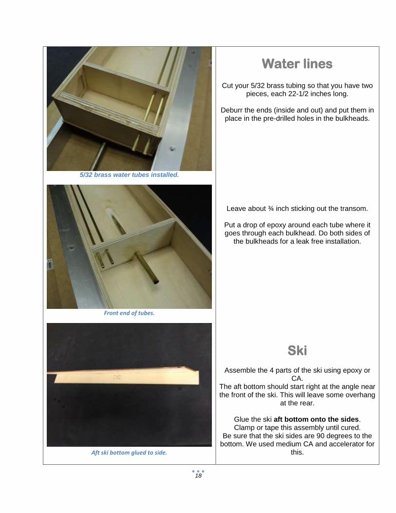
5/32 brass water tubes installed.
Front end of tubes.
Aft ski bottom glued to side.
Water lines
Cut your 5/32 brass tubing so that you have two pieces, each 22-1/2 inches long.
Deburr the ends (inside and out) and put them in
place in the pre-drilled holes in the bulkheads.
Leave about ¾ inch sticking out the transom.
Put a drop of epoxy around each tube where it goes through each bulkhead. Do both sides of
the bulkheads for a leak free installation.
Ski
Assemble the 4 parts of the ski using epoxy or CA.
The aft bottom should start right at the angle near the front of the ski. This will leave some overhang
at the rear.
Glue the ski aft bottom onto the sides. Clamp or tape this assembly until cured.
Be sure that the ski sides are 90 degrees to the bottom. We used medium CA and accelerator for
this.
19
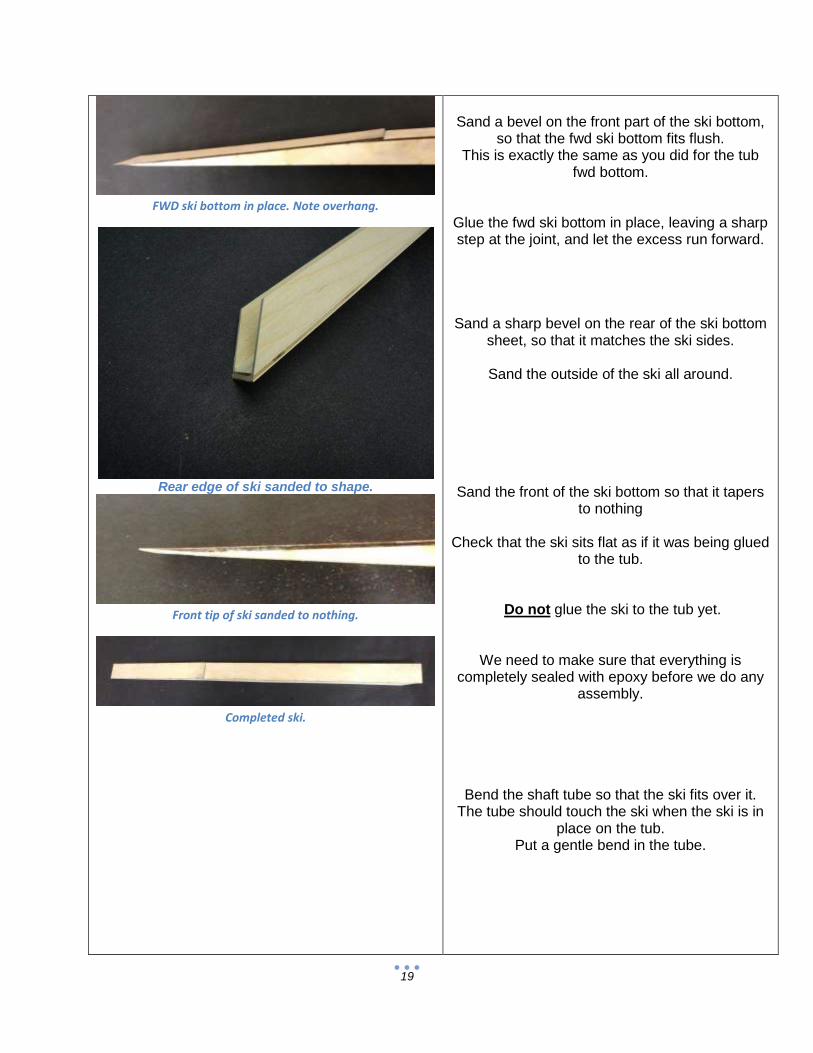
FWD ski bottom in place. Note overhang.
Rear edge of ski sanded to shape.
Front tip of ski sanded to nothing.
Completed ski.
Sand a bevel on the front part of the ski bottom,
so that the fwd ski bottom fits flush. This is exactly the same as you did for the tub
fwd bottom.
Glue the fwd ski bottom in place, leaving a sharp step at the joint, and let the excess run forward.
Sand a sharp bevel on the rear of the ski bottom sheet, so that it matches the ski sides.
Sand the outside of the ski all around.
Sand the front of the ski bottom so that it tapers to nothing
Check that the ski sits flat as if it was being glued
to the tub.
Do not glue the ski to the tub yet.
We need to make sure that everything is completely sealed with epoxy before we do any
assembly.
Bend the shaft tube so that the ski fits over it. The tube should touch the ski when the ski is in
place on the tub. Put a gentle bend in the tube.

20
Shaft tube bent for ski clearance.
Ski in place.
Strut in position (old strut shown).
Tape the ski in place over the shaft tube. We
want the ski to sit flat on the tub, and the strut to sit on the bottom of the ski at the rear.
Hardware If you are using Zipp hardware, simply finish drilling the holes in the transom for the strut,
rudder and pushrod.
If not, see below and fill any unused holes.
Strut
Make a pencil line in the center of the transom and mount the strut bracket flush with the top of
the transom.
Slide the strut onto the shaft tube and bolt in place.
Bolt the strut in the tub, touching the ski. The
shaft tube should go all the way through the Zipp strut. Slightly bend the shaft tube so that the strut
will slide on and bolt squarely to the transom.
The strut bottom should be parallel to the tub bottom (0 degree angle).
Mark the tube where it exits the strut. Remove the strut and cut the shaft tube at your mark. Clean and deburr this cut inside and out.
Remove the ski.

21
Strut sitting on rear of ski(old strut shown).
Rudder in position on bottom of transom.
Boom tube doublers ready to be laminated.
Rudder
Bolt the rudder in place. This should be as far to the left as possible and sitting on the bottom
sheet overhang (as low as possible).
Make a mark on the transom where the rudder pushrod will exit.
Sight this from behind the boat.
Drill a ¼ inch hole, on your mark.
Sponson Alignment
*This is a critical step in building your
boat. Make sure that you fully understand what we are doing, and don’t skip this
step!*
We need to make sure that both sponsons are exactly correct with reference to the tub. If they
are off, the boat will never handle properly.
The process is simple. Take your time, measure often and it will be fine.
The boom tube doublers are laminated from 1/8
inch ply and give added support to the aluminum
boom tubes.
Sand the edges and laminate the doublers using
CA or epoxy and allow to cure.
The laser cut parts are nearly perfect, but you
must be sure that both boom tubes are perfectly
level for the boat to run properly.
Block up the tub so that it is level (side to side).
You will have to use blocks that are thick enough
to keep the shaft tube off the bench.
Weight the tub so that it can’t move around.
22
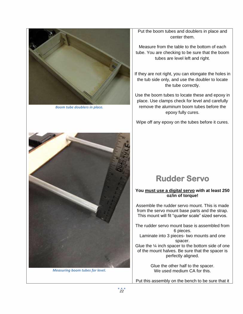
Boom tube doublers in place.
Measuring boom tubes for level.
Put the boom tubes and doublers in place and
center them.
Measure from the table to the bottom of each
tube. You are checking to be sure that the boom
tubes are level left and right.
If they are not right, you can elongate the holes in
the tub side only, and use the doubler to locate
the tube correctly.
Use the boom tubes to locate these and epoxy in
place. Use clamps check for level and carefully
remove the aluminum boom tubes before the
epoxy fully cures.
Wipe off any epoxy on the tubes before it cures.
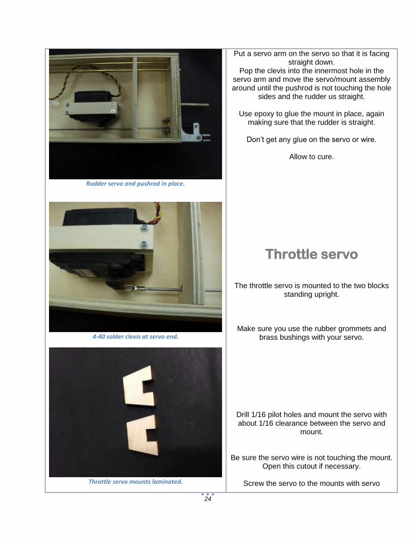
Rudder Servo
You must use a digital servo with at least 250 oz/in of torque!
Assemble the rudder servo mount. This is made from the servo mount base parts and the strap. This mount will fit “quarter scale” sized servos.
The rudder servo mount base is assembled from
6 pieces. Laminate into 3 pieces- two mounts and one
spacer. Glue the ¼ inch spacer to the bottom side of one of the mount halves. Be sure that the spacer is
perfectly aligned.
Glue the other half to the spacer. We used medium CA for this.
Put this assembly on the bench to be sure that it

23
Rudder servo mounts being laminated.
Servo mount assembled.
Quarter scale servo in place on mount.
sits flat.
Clamp until cured. Laminate the servo strap the same way.
Check the height of your servo. The mount should be a tiny bit shorter than your servo.
If necessary, sand the top of the mounts slightly until the servo is about 1/32 inch taller.
Set the ¼ ply strap in place and drill pilot holes
with a 1/16 bit. Do not omit these or the ply will split.
Put the servo in place and clamp it down with the
strap and 4 servo screws. Notice that the screws only need to be snug to
hold the servo securely in place.
This mount puts the servo arm in the correct position for a straight pushrod run to the rudder.
We will use the innermost servo arm hole.
Thread a 4-40 ball link onto a 4/40 pushrod.
Slip this into the hole in the transom and bulkhead and attach it to the rudder with a 4-40
screw and nut.
Sand the bottom of the servo mount so that it is flat.
Put the servo/mount assembly in position about 1
inch forward of the rear bulkhead. Mark the pushrod where the servo output shaft
is.
Remove the pushrod. Cut the pushrod and solder a clevis in place so
that its pin is where the mark was.
Put the pushrod back in place.
24
Rudder servo and pushrod in place.
4-40 solder clevis at servo end.
Throttle servo mounts laminated.
Put a servo arm on the servo so that it is facing straight down.
Pop the clevis into the innermost hole in the servo arm and move the servo/mount assembly around until the pushrod is not touching the hole
sides and the rudder us straight.
Use epoxy to glue the mount in place, again making sure that the rudder is straight.
Don’t get any glue on the servo or wire.
Allow to cure.
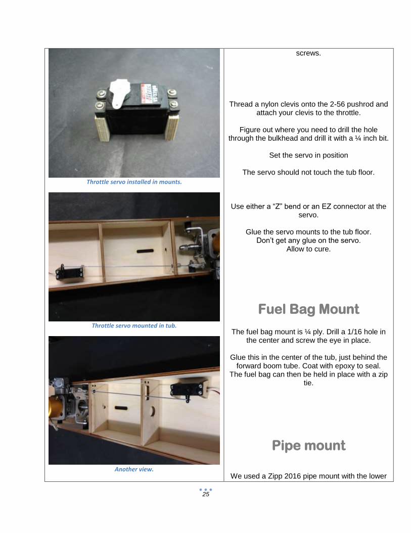
Throttle servo
The throttle servo is mounted to the two blocks standing upright.
Make sure you use the rubber grommets and brass bushings with your servo.
Drill 1/16 pilot holes and mount the servo with about 1/16 clearance between the servo and
mount.
Be sure the servo wire is not touching the mount. Open this cutout if necessary.
Screw the servo to the mounts with servo
25
Throttle servo installed in mounts.
Throttle servo mounted in tub.
Another view.
screws.
Thread a nylon clevis onto the 2-56 pushrod and attach your clevis to the throttle.
Figure out where you need to drill the hole
through the bulkhead and drill it with a ¼ inch bit.
Set the servo in position
The servo should not touch the tub floor.
Use either a “Z” bend or an EZ connector at the servo.
Glue the servo mounts to the tub floor.
Don’t get any glue on the servo. Allow to cure.
Fuel Bag Mount
The fuel bag mount is ¼ ply. Drill a 1/16 hole in the center and screw the eye in place.
Glue this in the center of the tub, just behind the
forward boom tube. Coat with epoxy to seal. The fuel bag can then be held in place with a zip
tie.
Pipe mount
We used a Zipp 2016 pipe mount with the lower

26
Fuel cell in place. Note zip tie.
Pipe mount in place.
Pipe mount screwed into “bait box”.
portion cut off.
Try to get the pipe mount in the “bait box” area of
the tub so that you are not drilling into the radio
box.
We simply bolted this to the tub side.
Note that our tuned pipes are handmade and not
perfectly concentric. While this makes no
difference for performance, it does mean that you
can rotate the pipe to get the distance from the
mount to the tub correct.
Remove everything in preparation for sealing
Sealing
Using epoxy finishing resin or West Systems
epoxy, seal the inside of the tub. Seal every part
of the wood. In the boom tube holes, etc.
Allow this to cure and apply a second coat.
Be sure that there is no buildup in the little recess
for the radio box lip.
You can also seal the underside of the radio box
lid, lid frame and the top deck at this time.
Allow to cure
Top Deck The first step is to get the tub blocked up so that
it is flat on the bench. You can use pieces of ¾
ply or some scrap wood at least ¾ inch thick.
This is needed to prevent damage to the shaft

27
Radio box lid frame in place.
Tub top taped in place. Note that it is centered on radio box
lip.
Tub top taped in place. Note that it is centered on radio box
lip.
tube.
When we attach the deck, we will “lock in” the
shape of the tub. If there is any twist, this will
make it permanent.
Make sure that there is no twist.
if you want to be perfect, you can put the boom
tubes in place and measure from the bench to be
sure that the tub is level.
Before we get to the top deck, we need to glue in
the radio box lid frame. This frame provides the “lip” around the radio box
for the lit to sit in.
Check all around the area where the frame will go, and look for any glue that will prevent it from
sitting flush with the outer sides. If you find anything, a single edge razor can be
used to scrape it away.
Once you are happy with the fit of the lid frame, glue it in place, sealed side down.
Tape and weight this, and be sure that it is all the way against bulkhead 3 and flush with the rest.
Allow to cure.
Once the lid frame is cured, sand the entire top of the tub in preparation for the top deck. Also sand the first coat of sealer on the
underside of the deck with 80.
Test fit the top deck, and be sure that you center the “lip” in the radio box area, and that there is a
little overhang all around.
When you are happy with the fit of the top deck, mix up some 30 minute epoxy.
Using a brush or scraper, coat the underside of the deck with a second coat of epoxy. Get the whole deck as it needs to be waterproof. Work
quickly. Coat the tops of the bulkheads and tub sides.
Also coat the top of the lid frame.
28
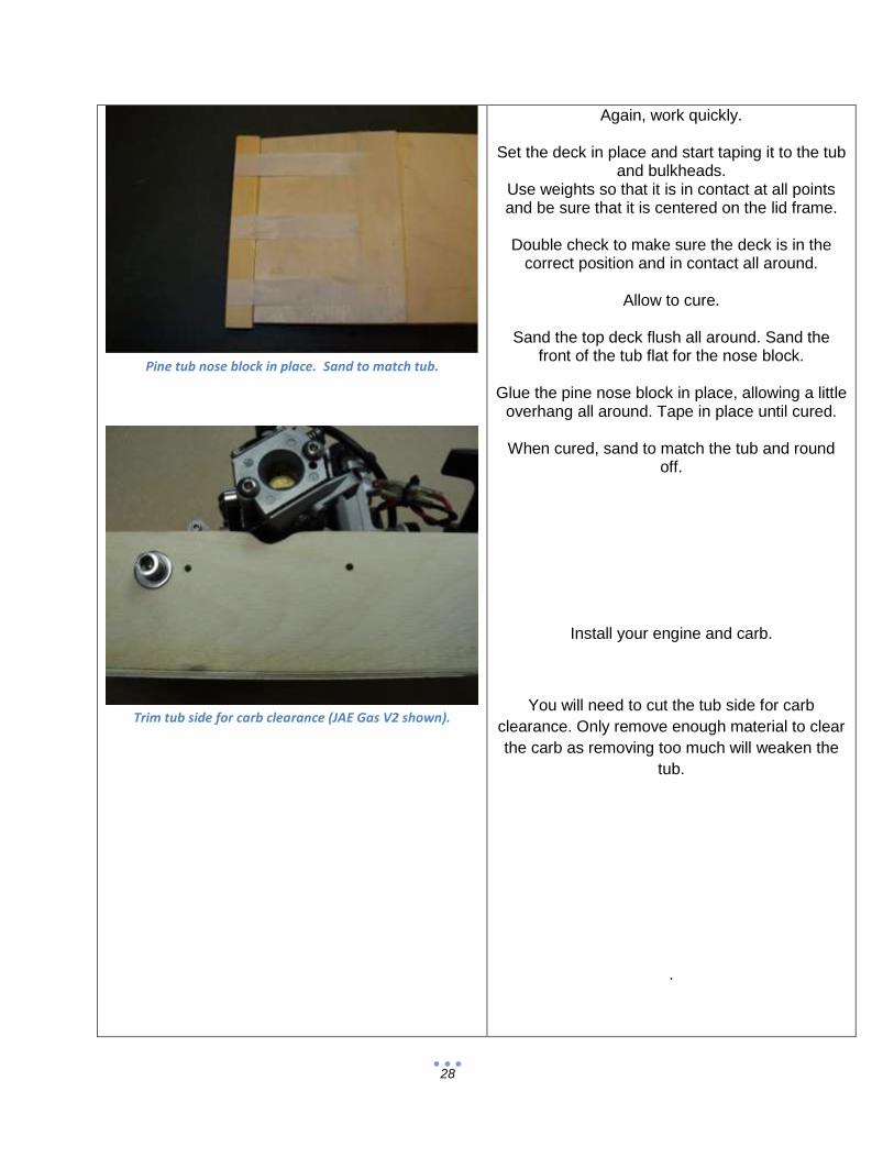
Pine tub nose block in place. Sand to match tub.
Trim tub side for carb clearance (JAE Gas V2 shown).
Again, work quickly.
Set the deck in place and start taping it to the tub and bulkheads.
Use weights so that it is in contact at all points and be sure that it is centered on the lid frame.
Double check to make sure the deck is in the
correct position and in contact all around.
Allow to cure.
Sand the top deck flush all around. Sand the front of the tub flat for the nose block.
Glue the pine nose block in place, allowing a little
overhang all around. Tape in place until cured.
When cured, sand to match the tub and round off.
Install your engine and carb.
You will need to cut the tub side for carb
clearance. Only remove enough material to clear
the carb as removing too much will weaken the
tub.
.

29
Sponson parts. Dowels not shown.
Be sure to make a right and left sponson…
Sponsons
The sponsons are assembled in a specific order for a reason. It is not the fastest way, but it’s the only way it can be done right.
Gather all of the parts for the right sponson.
The right sponson holds the turn fin, so it has dowels in it,
Grab the right foam sponsons.
Test fit the 5/8 inch wood dowels in the 3 rear holes. Also test fit the 2 aluminum plugs. They should be a nice fit, without slop.
Prepare the sponson inside and outside plates by lightly sanding the edges.
Put the RH sponson outside (3 big holes) on the
bench.
Mix up some 30 minute epoxy, and coat the inside of the sponson plates and both sides of
the foam sponsons. Laminate the foam sponsons and add the 1/8 ply
sponson plates. Work quickly.
Put epoxy in the holes, and insert the 3 wood
dowels. They should bottom out on the outer plate and
stick up above the inside plate. Work quickly.
Use the aluminum sponson plugs to make sure
all pieces are properly aligned.
Use tape and small weights to hold the sponson and check the length of the sponson with a
straightedge or ruler. It should be straight and flat.
Allow to cure on waxed paper.

30
Aluminum plug used for alignment now.
Sponsons are mirror images. Dowels are on right sponson.
Sharp inside corner.
Carefully remove and the aluminum plugs from the sponsons and wipe off any epoxy before it
cures. Be sure that the plates do not slide around before the epoxy cures.
While the right sponson is curing, you can glue the left sponson. Everything is the same, except the left sponson has no dowels and both plates
are the same.
Glue the plates and foam as before, and weight or clamp until cured.
When the sponson sides are cured, let’s do the sheeting. This is where the strange order comes in. The sheeting is done in this order because it
has to overlap in a specific way. Follow along and you won’t have any trouble. If something doesn’t seem to fit, stop and find out
why. Epoxy is impossible to remove from foam…
Grab all the sheeting pieces.
Use a file to sharpen the inside corner of the sponson step as shown.
Use your sanding block with 80 grit paper to sand the foam flush with both sponson plates.
Using epoxy, glue S-1 in place on the sponson
step. Use masking tape to hold it in place while it cures.
It’s okay to repeat the steps on the other sponson. S-1 and S-2 are 1/16 ply.
Glue S-2 to the sponson rear.

31
Sponson sheeting order. Needed for correct overhangs.
1 glued in place and sanded flush.
3 and 4 in place, with overhangs.
Once these have cured, sand the bottom and sides of S-2 and S-1 flush.
2 glued in place.
Glue S-3 in place. S-3 is 1/16 ply.
Glue S-4 and leave an overhang in the rear. S-4 is 1/8 ply.
It should be aligned to the “break” where the sponson bottom changes angle (for S5) and
overhang at the rear.
32
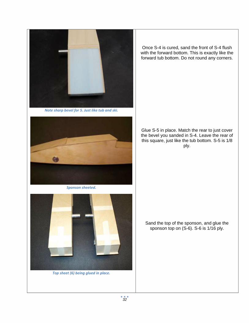
Note sharp bevel for 5. Just like tub and ski.
Sponson sheeted.
Top sheet (6) being glued in place.
Once S-4 is cured, sand the front of S-4 flush with the forward bottom. This is exactly like the forward tub bottom. Do not round any corners.
Glue S-5 in place. Match the rear to just cover the bevel you sanded in S-4. Leave the rear of this square, just like the tub bottom. S-5 is 1/8
ply.
Sand the top of the sponson, and glue the sponson top on (S-6). S-6 is 1/16 ply.
33
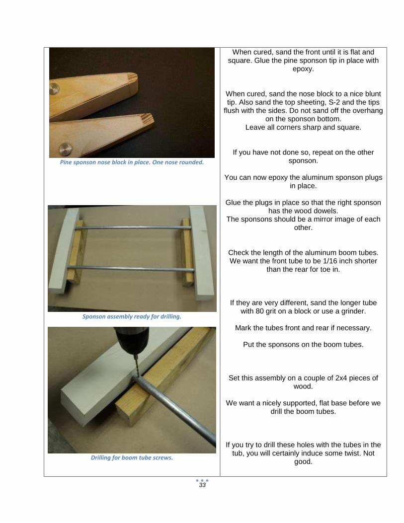
Pine sponson nose block in place. One nose rounded.
Sponson assembly ready for drilling.
Drilling for boom tube screws.
When cured, sand the front until it is flat and square. Glue the pine sponson tip in place with
epoxy.
When cured, sand the nose block to a nice blunt tip. Also sand the top sheeting, S-2 and the tips
flush with the sides. Do not sand off the overhang on the sponson bottom.
Leave all corners sharp and square.
If you have not done so, repeat on the other sponson.
You can now epoxy the aluminum sponson plugs
in place.
Glue the plugs in place so that the right sponson has the wood dowels.
The sponsons should be a mirror image of each other.
Check the length of the aluminum boom tubes. We want the front tube to be 1/16 inch shorter
than the rear for toe in.
If they are very different, sand the longer tube with 80 grit on a block or use a grinder.
Mark the tubes front and rear if necessary.
Put the sponsons on the boom tubes.
Set this assembly on a couple of 2x4 pieces of wood.
We want a nicely supported, flat base before we
drill the boom tubes.
If you try to drill these holes with the tubes in the tub, you will certainly induce some twist. Not
good.

34
6-32 screw…
And nut.
Turn Fin. Note adjustment slots.
When everything is looking good, drill a 5/32 hole through the aluminum boom tube and the
sponson plug.
Put the supplied 6-32 screw and locknut in place. Do this for all 4 corners.
Remove the right sponson, but leave the left one attached to the boom tubes.
Turn Fin
The turn fin is a critical part of the handling of the JAE gas outrigger.

35
Turn fin sharpened.
Figure 1
Turn fin mounted with nuts inside for safety.
Take the time to get this correct, as the number one reason the boat does something stupid is the
turn fin.
Check to see if the fin is flat (front to rear). The rolling process can induce a slight “cupping” of
the fin. If you find this, file or block sand until it is gone.
Sharpen the outside (RH) of the turn fin. Make a bevel at least 3/8 inch wide along the
front and bottom of the fin.
Mark the center of the turn fin dowels. Drill 3/16 holes on your marks. Drill these holes
using a drill press if available. Drill only about half way, flip the sponson over and drill from the other
side.
Attach the turn fin with the supplied screws, nuts and washers.
Note that you can later fine tune the fin with the oversized, slotted holes.
Remove the turn fin in preparation for finishing.
36
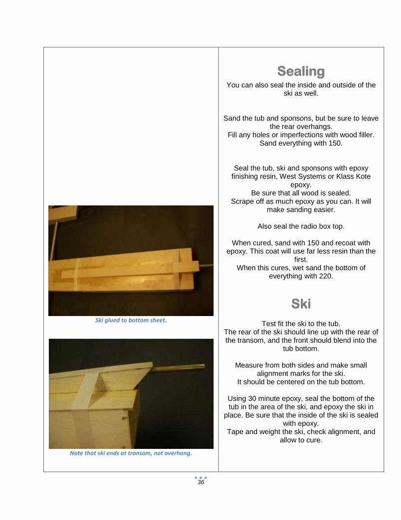
Ski glued to bottom sheet.
Note that ski ends at transom, not overhang.
Sealing You can also seal the inside and outside of the
ski as well.
Sand the tub and sponsons, but be sure to leave the rear overhangs.
Fill any holes or imperfections with wood filler. Sand everything with 150.
Seal the tub, ski and sponsons with epoxy finishing resin, West Systems or Klass Kote
epoxy. Be sure that all wood is sealed.
Scrape off as much epoxy as you can. It will make sanding easier.
Also seal the radio box top.
When cured, sand with 150 and recoat with
epoxy. This coat will use far less resin than the first.
When this cures, wet sand the bottom of everything with 220.
Ski
Test fit the ski to the tub. The rear of the ski should line up with the rear of the transom, and the front should blend into the
tub bottom.
Measure from both sides and make small alignment marks for the ski.
It should be centered on the tub bottom.
Using 30 minute epoxy, seal the bottom of the tub in the area of the ski, and epoxy the ski in
place. Be sure that the inside of the ski is sealed with epoxy.
Tape and weight the ski, check alignment, and allow to cure.

37
Shaft with flat spot for drive dog screw.
Finishing
If you are painting sand the entire boat with 220. Now is the time for primer. Wet sand the primer
with 400, and use spot putty to fill any imperfections. Wet sand with 400 and lay on a
heavy coat of primer. Wet sand with 600-800 and paint.
Use fuel proof paint or fuel proof clear.
If you are going to keep the boat natural, use a UV safe epoxy, or automotive clear as a final
coat.
Final Assembly
Bolt the strut to the transom. Make sure that the strut is straight up.
The strut needs to be at the very bottom of the
ski for the proper propeller depth. Make the ski parallel with the tub bottom (0
degree angle).
Slide your drive dog onto your flex shaft, then your prop. Leave about half of the threads
showing past the prop. Tighten the drive dog set screw.
Remove the prop and measure the exact location
of the set screw from the end of the shaft. Remove the drive dog and file or grind a flat spot
on the shaft about 1/8 inch wide. Put the drive dog back on the shaft, aligning the set screw in
the flat you made.
Push the flex shaft into the shaft tube, and into the collet. Make sure that the shaft goes all the way into the collet. Measure the distance from
the back of the strut to the front of the drive dog. Subtract 3/8 inch.

38
Drive dog, prop and prop nut in place.
Note ¼ inch gap at drive dog.
Ready to rock! Optional cowling shown.
Cut this amount off of the flex shaft. This allows you to put the shaft all the way into the collet, and
still have a 3/8 gap between the strut and drive dog. This is needed because the flex shaft will twist slightly at high speeds, and actually get
shorter.
Bolt the rudder in place. Be sure that it is straight up and down.
Setup
Put the boom tubes in place and slide on the 5/8
boom tube clamps. Note- if you want to protect the tub from the collars rubbing, you can use some rubber
washers for a garden hose. They are the correct size…
Bolt the sponsons on with the 6-32x7/8 screws
and locknuts.
Measure the sponsons and adjust until the right sponson has toe in and the left is straight. The sponsons should be centered (equal
distance from the tub).
Turn on the radio. Make sure that the steering trim is in the center. Move the steering servo arm so that it is straight
down. Put the servo arm screw in.
Mount the throttle servo arm so that it is at about 2 o’clock with the trigger at neutral.
Put the servo arm screw in.
Install the servos and pushrods again, only this time, glue pushrod seals in place with Goop.
Wrap your receiver and battery pack with foam .
Assemble the fuel bag and mount with a zip tie
Mount the rudder and attach the pushrod.
Screw the ball link in or out to center the rudder. Check for correct rudder movement.
Attach the throttle pushrod clevis to the carb arm,
39
and put an EZ connector in the servo arm. Set the carb so that it is slightly open with the trigger
at neutral.
Open the throttle and check to see if you get full open. If not, move the Z bend out farther on the servo arm, farther in on the carb arm, or adjust your throttle end point in your radio until it does.
Also push the trigger (brake) to make sure that the throttle closes fully. You should remove the
throttle stop screw on the carb. Take the time to get this right. If you don’t, your boat won’t shut off and will be embarrassing and
dangerous.
Mount your switch with a waterproof switch cover.
Make sure that your tuned pipe is mounted to the
tub.
Make sure your prop is sharpened and balanced.
Grease the flex shaft with cable grease or high quality marine grease. Install the flex cable.
Hook up your fuel and water lines.
You must use a cowling or carb spray shield to
keep water out of the engine.
Running
The main thing is to get the boat running smoothly and turning well. After that, try different
props and pipe lengths.
For a bunch of help tuning and running, go to some of the R/C boating web sites.
One of the most popular is International Waters (www.intlwaters.com).
Good luck and happy boating!

40
Additional information
International Waters Website
www.intlwaters.com
Excellent forum for information on R/C boats
lots of general JAE discussion
Klass Kote Epoxy Paint
www.klasskote.com Phone (612) 243-1234
Source for the best epoxy paints
Servo City
www.servocity.com Phone (620) 221-0123
Best servo prices around
41
Setup and Adjustment
Make absolutely certain that the rudder leading edge is straight, with positively no taper or kick
back. The boat hates this, as it lifts the rear and causes all sorts of issues.
Set the turn fin so that the top of the fin is parallel with the top of the sponson.
If using an adjustable strut, set it flat on the ski (0 degrees).
Set rudder throw to 10 degrees right and left. Use the least amount of throw on the servo arm,
and use your radio’s ATV or end point adjustment to reduce it further. Do not exceed these
throws!
Run the boat. If it looks loose at full throttle, adjust the fin angle back slightly.
Measure from a convenient point, like the rudder. Adjust the fin 1/16 inch, no more.
Do not exceed 1/16 inch increments. The fin adjustment is very, very sensitive, and it is easy to
go too far.
As you adjust the fin forward, the boat rides loose, and adjusted back, the boat rides wet.
If the boat rides up in the turn fin, especially with left rudder, the fin is angled too far forward.
Tips
Do not change the ride attitude or height. Leave the AOA alone. The hull is good for over 100
mph as is.
The boat will not turn sharp left. You can make left corrections, but if you push it, it will flip.
Try different props. The Zipp 2716 is a good start We also like the ABC 3016/2 and 3018/2.
Do not cut the rudder. You need all you can get to control prop walk.
If you heat race in rough water, you can add a bit of dihedral on the left sponson bottom to help
keep the boat locked into turns when it gets really bad. Just sand the bottom of the LH sponson
so that the outside is .080 off the bench and seal with epoxy.
Remember, this is a different boat design than most other outriggers.
If you need advice, contact us.
If you take advice from others, consider what experience they have with JAE design hulls.
If someone tells you to make changes to the strut, ski, angle of attack, etc., maybe consider the
value of this advice.

42
The bottom line is that the boat works very well as is. If you make any changes, it will not be the
same boat, as it was designed as a system, with all aspects working together.
We can provide any help you may need for building, setup and running.
We encourage you to experiment with different props and pipe settings.
Props make all the difference in the world, as far as speed and handling go.
We can be reached by email at [email protected]
Or
By Phone Toll Free at (866) 922-9477
When you finish your Envy rigger, why not send us pictures for our web site?
We would love to see them.
Pictures of the boat sitting in the water are our favorite…