envision residential installation manual - waterfurnace · 7 envision residential installation...
TRANSCRIPT

IM1000AN 12/09
Installation Information
Water Piping Connections
Hot Water Generator Connections
Electrical
Startup Procedures
Troubleshooting
Preventive Maintenance
Envis
ion
Resi
den
tial In
stalla
tio
n M
an
ual
Geothermal/Water Source Heat Pumps • R-410A Refrigerant
• 2, 2.5, 3, 3.5, 4, 5, 6 Ton Single Speed
• 2, 3, 4, 5, 6 Ton Dual Capacity
RESIDENTIAL


ENVISION RESIDENTIAL INSTALLATION MANUAL
Table of Contents
Model Nomenclature. . . . . . . . . . . . . . . . . . . . . . . . . . . . . . . . . . . . . . . . . . . . . . . . . . . . . . . . . . . 4
General Installation Information . . . . . . . . . . . . . . . . . . . . . . . . . . . . . . . . . . . . . . . . . . . . . . . .5-9
Closed Loop Ground Source Systems . . . . . . . . . . . . . . . . . . . . . . . . . . . . . . . . . . . . . . . . . . . .10
Open Loop Ground Water Systems . . . . . . . . . . . . . . . . . . . . . . . . . . . . . . . . . . . . . . . . . . . . . . 11
Hot Water Generator Connections and Startup . . . . . . . . . . . . . . . . . . . . . . . . . . . . . . . . . 12-13
Electrical Connections . . . . . . . . . . . . . . . . . . . . . . . . . . . . . . . . . . . . . . . . . . . . . . . . . . . . . . 14-15
Electronic Thermostat Installation . . . . . . . . . . . . . . . . . . . . . . . . . . . . . . . . . . . . . . . . . . . . . . . 15
Auxiliary Heat Ratings . . . . . . . . . . . . . . . . . . . . . . . . . . . . . . . . . . . . . . . . . . . . . . . . . . . . . . . . . 15
Electrical Data . . . . . . . . . . . . . . . . . . . . . . . . . . . . . . . . . . . . . . . . . . . . . . . . . . . . . . . . . . . . . . . .16
Fan Performance Data . . . . . . . . . . . . . . . . . . . . . . . . . . . . . . . . . . . . . . . . . . . . . . . . . . . . . . 17-18
Vertical Dimensional Data . . . . . . . . . . . . . . . . . . . . . . . . . . . . . . . . . . . . . . . . . . . . . . . . . . . 19-21
Horizontal Dimensional Data . . . . . . . . . . . . . . . . . . . . . . . . . . . . . . . . . . . . . . . . . . . . . . . . . . . 22
Physical Data . . . . . . . . . . . . . . . . . . . . . . . . . . . . . . . . . . . . . . . . . . . . . . . . . . . . . . . . . . . . . 23-24
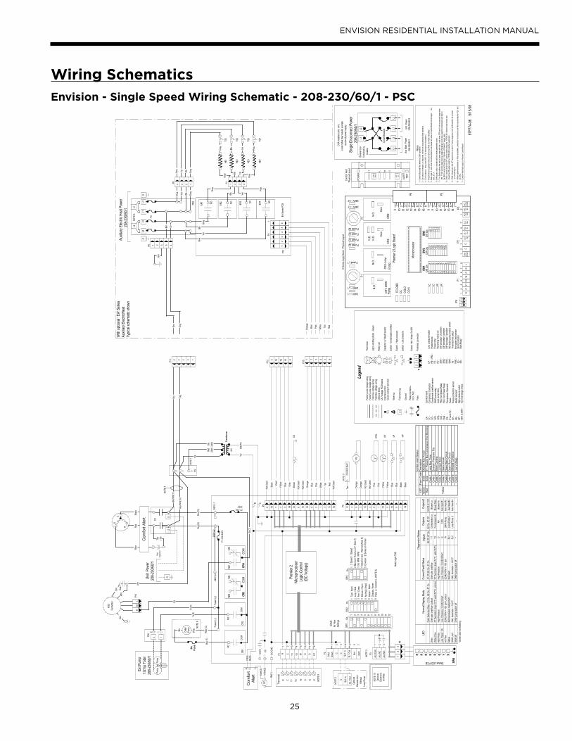
Wiring Schematics. . . . . . . . . . . . . . . . . . . . . . . . . . . . . . . . . . . . . . . . . . . . . . . . . . . . . . . . . 25-29
Microprocessor Control . . . . . . . . . . . . . . . . . . . . . . . . . . . . . . . . . . . . . . . . . . . . . . . . . . . . 30-35
Unit Startup . . . . . . . . . . . . . . . . . . . . . . . . . . . . . . . . . . . . . . . . . . . . . . . . . . . . . . . . . . . . . . . . . 36
Operation Logic. . . . . . . . . . . . . . . . . . . . . . . . . . . . . . . . . . . . . . . . . . . . . . . . . . . . . . . . . . . . . . 37
Unit Operating Parameters . . . . . . . . . . . . . . . . . . . . . . . . . . . . . . . . . . . . . . . . . . . . . . . . . 38-39
Pressure Drop. . . . . . . . . . . . . . . . . . . . . . . . . . . . . . . . . . . . . . . . . . . . . . . . . . . . . . . . . . . . . . . . 40
Troubleshooting. . . . . . . . . . . . . . . . . . . . . . . . . . . . . . . . . . . . . . . . . . . . . . . . . . . . . . . . . . . . . . .41
Preventive Maintenance . . . . . . . . . . . . . . . . . . . . . . . . . . . . . . . . . . . . . . . . . . . . . . . . . . . . . . . 42
Replacement Procedures . . . . . . . . . . . . . . . . . . . . . . . . . . . . . . . . . . . . . . . . . . . . . . . . . . . . . . 42

4
ENVISION RESIDENTIAL INSTALLATION MANUAL
Model Nomenclature
1 2 3
N D V
4-6
048
7
A
8
1
9
1
10
1
11
C
12
T
13
L
14-15
AP
Model Type N = Envision
Compressor Type D = Dual Capacity
S = Single Speed
Cabinet Configuration V = Vertical
H = Horizontal
Unit Capacity
Vintage A = 036-072 top discharge & horizontal
022-072 bottom & rear discharge
B = 022-026-030 top discharge & horizontal
Voltage 1 = 208-230/60/1
Hot Water Options 0 = No Hot Water Generation, No IntelliStartTM
1 = Hot Water Generation with factory
installed pump, No IntelliStart
3 = No Hot Water Generation, IntelliStart
4 = Hot Water Generation with factory
installed pump, IntelliStart
NOTES: All models include sound kits as standard equipment.
* Vertical configurations only
Filter Option AP = AlpinePure 411*
Blank = 2” MERV 11 Filter
Return Air Configuration L = Left
R = Right
Discharge Air Configuration T = Top
S = Side
E = End
B = Bottom
R = Rear
Coax Options C = Copper
N = Cupronickel
Fan Options 0 = PSC
1 = ECM
2 = Oversized ECM
(036, 038, 042, 048, 049)
3 = Oversized PSC
(022, 030, 036, 042, 048)
Residential

5
ENVISION RESIDENTIAL INSTALLATION MANUAL
Moving and StorageMove units in the normal “up” orientation. Horizontal units may be moved and stored per the information on the packaging.
Do not stack more than three units in total height. Vertical units may be stored one upon another to a maximum height
of two units. Do not attempt to move units while stacked. When the equipment is received, all items should be carefully
checked against the bill of lading to be sure all crates and cartons have been received. Examine units for shipping damage,
removing the units from the packaging if necessary. Units in question should also be internally inspected. If any damage is
noted, the carrier should make the proper notation on the delivery receipt, acknowledging the damage.
Unit LocationLocate the unit in an indoor area that allows for easy removal of the filter and access panels. Location should have enough
space for service personnel to perform maintenance or repair. Provide sufficient room to make water, electrical and duct
connection(s). If the unit is located in a confined space, such as a closet, provisions must be made for return air to freely
enter the space by means of a louvered door, etc. Any access panel screws that would be difficult to remove after the
unit is installed should be removed prior to setting the unit. On horizontal units, allow adequate room below the unit for
a condensate drain trap and do not locate the unit above supply piping. Care should be taken when units are located in unconditioned spaces to prevent damage from frozen water lines and excessive heat that could damage electrical
components.
Installing Vertical UnitsPrior to setting the unit in place, remove and discard the compressor hold down
shipping bolt located at the front of the compressor mounting bracket.
Vertical units are available in left or right air return configurations. Top and rear
air discharge vertical units should be mounted level on a vibration absorbing pad
slightly larger than the base to provide isolation between the unit and the floor. It is
not necessary to anchor the unit to the floor (see right).
Bottomflow units should be mounted level and sealed well to floor to prevent air
leakage. Bottomflow units require the supply air opening to be cut at least 1/2˝
larger than the unit’s air outlet. Protect the edges of combustible flooring with sheet
metal over-wrap or other non-combustible material.
WARNING: Before performing service or maintenance operations on a system, turn off main power switches to the indoor unit. If applicable, turn off the accessory heater power switch. Electrical shock could cause personal injury.
Installing and servicing heating and air conditioning equipment can be hazardous due to system pressure and electrical
components. Only trained and qualified service personnel should install, repair or service heating and air conditioning
equipment. Untrained personnel can perform the basic maintenance functions of cleaning coils and cleaning and
replacing filters. All other operations should be performed by trained service personnel. When working on heating and
air conditioning equipment, observe precautions in the literature, tags and labels attached to the unit and other safety
precautions that may apply.
Follow all safety codes. Wear safety glasses and work gloves. Use a quenching cloth for brazing operations and have a fire
extinguisher available.
Safety Considerations
General Installation Information
Figure 1: Vertical Unit Mounting
2” ExtrudedPolystyrene

6
ENVISION RESIDENTIAL INSTALLATION MANUAL
Installing Horizontal UnitsRemove and discard the compressor hold down shipping bolt located at the front of the compressor mounting bracket
prior to setting the unit in place. Horizontal units are available with side or end discharge. Horizontal units are normally
suspended from a ceiling by six 3/8-inch diameter threaded rods. The rods are usually attached to the unit by hanger
bracket kits furnished with each unit.
Lay out the threaded rods per the dimensions below. Assemble the hangers to the unit as shown. Securely tighten the
brackets to the unit using the weld nuts located on the underside of the bottom panel. When attaching the hanger rods to
the bracket, a double nut is required since vibration could loosen a single nut. To allow filter access, one bracket on the filter
side should be installed 180° from the position shown in the figure below. The unit should be pitched approximately 1/4-inch
towards the drain in both directions to facilitate the removal of condensate. Use only the bolts provided in the kit to attach
hanger brackets. The use of longer bolts could damage internal parts.
Some residential applications require the installation of horizontal units on an attic floor. In this case, the unit should be
set in a full size secondary drain pan on top of a vibration absorbing pad. The secondary drain pan prevents possible
condensate overflow or water leakage damage to the ceiling. The secondary drain pan is usually placed on a plywood base
isolated from the ceiling joists by additional layers of vibration absorbing material.
CAUTION: Do not use rods smaller than 3/8-inch diameter since they may not be strong enough to support the unit. The rods must be securely anchored to the ceiling.
General Installation Information cont.
Insulate supplyplenum and useat least one 90 elbow toreduce noise
Electrical Disconnect
Flexible DuctCollar
Threaded Rods
Line Voltage Ball Valves
HoseKits
To LinePower
ToThermostat
HangingBrackets(Included)
Building Water Loop
O
Figure 2: Horizontal Unit Mounting
Figure 3: Hanger Location and Assembly
3/8" ThreadedRod (by others)
Hex Nuts (2)(by others)
Washer
VibrationIsolator
Bolt andLock Washer
A
24.8
27.8
27.8
27.8
25.1
25.1
Model
022 - 030*
036 - 038
042 - 049
060 - 072
009 - 012*
015 - 018*
Hanger KitPart Number
995500A04
995500A03
995500A03
995500A03
995500A04
995500A04
B
63.4
72.4
77.4
82.4
44.7
53.7
C
21.1
24.1
24.1
24.1
21.4
21.4
D
N/A
43.1
48.1
53.1
N/A
N/A
E
N/A
29.3
29.3
29.3
N/A
N/A
F
1.1
1.1
1.1
1.1
1.3
1.3
NOTE: *Only the four corner brackets are needed on sizes 009-030.
C
F B
Air Coil
Air Coil
DE
A

7
ENVISION RESIDENTIAL INSTALLATION MANUAL
Duct SystemAn air outlet collar is provided on vertical top and rear air discharge units and all horizontal units to facilitate a duct
connection (vertical bottomflow units have no collar). A flexible connector is recommended for discharge and return air
duct connections on metal duct systems. Uninsulated duct should be insulated with a minimum of 1-inch duct insulation.
Application of the unit to uninsulated ductwork in an unconditioned space is not recommended as the unit’s performance
will be adversely affected.
If the unit is connected to existing ductwork, check the duct system to ensure that it has the capacity to accommodate the
air required for the unit application. If the duct is too small, as in the replacement of heating only systems, larger ductwork
should be installed. All existing ductwork should be checked for leaks and repaired if necessary.
The duct system should be sized to handle the design airflow quietly and efficiently. To maximize sound attenuation of the
unit blower, the supply and return plenums should include an internal duct liner of fiberglass or constructed of ductboard
for the first few feet. On systems employing a sheet metal duct system, canvas connectors should be used between the unit
and the ductwork. If air noise or excessive airflow is a problem, the blower speed can be changed.
Water PipingThe proper water flow must be provided to each unit whenever the
unit operates. To assure proper flow, use pressure/temperature ports
to determine the flow rate. These ports should be located at the supply
and return water connections on the unit. The proper flow rate cannot
be accurately set without measuring the water pressure drop through
the refrigerant-to-water heat exchanger.
All source water connections on commercial units are fittings that
accept a male pipe thread (MPT). Insert the connectors by hand, then
tighten the fitting with a wrench to provide a leakproof joint. When
connecting to an open loop (groundwater) system, thread any copper
MPT fitting into the connector and tighten in the same manner as
described above.
All source water connections on residential units are swivel piping
fittings (see Figure 4) that accept a 1-inch male pipe thread (MPT).
The swivel connector has a rubber gasket seal similar to a rubber hose
gasket, which when mated to the flush end of any 1-inch threaded
pipe provides a leak-free seal without the need for thread sealing tape
or compound. Check to ensure that the rubber seal is in the swivel
connector prior to attempting any connection. The rubber seals are
shipped attached to the waterline. To make the connection to a ground
loop system, mate the brass connector (supplied in CK4L connector kit) against the rubber gasket in the swivel connector
and thread the female locking ring onto the pipe threads, while maintaining the brass connector in the desired direction.
Tighten the connectors by hand, then gently snug the fitting with pliers to provide a leak-proof joint. When connecting to
an open loop (ground water) system, thread any 1-inch MPT fitting (SCH80 PVC or copper) into the swivel connector and
tighten in the same manner as noted above. The open and closed loop piping system should include pressure/temperature
taps for serviceability.
Never use flexible hoses smaller than 1-inch inside diameter on the unit. Limit hose length to 10 feet per connection. Check
carefully for water leaks.
Figure 4: Swivel Connections (Residential Units)
LockingRing
StainlessSteelSnap Ring
GasketSupportSleeve
GasketMaterial
CAUTION: Be sure to remove the shipping material from the blower discharge before connecting ductwork.
General Installation Information cont.

8
ENVISION RESIDENTIAL INSTALLATION MANUAL
Water QualityIn ground water situations where scaling could be heavy or where biological growth such as iron bacteria will be present,
a closed loop system is recommended. The heat exchanger coils in ground water systems may, over a period of time, lose
heat exchange capabilities due to a buildup of mineral deposits inside. These can be cleaned, but only by a qualified service
mechanic, as special solutions and pumping equipment are required. Hot water generator coils can likewise become scaled
and possibly plugged. In areas with extremely hard water, the owner should be informed that the heat exchanger may
require occasional flushing.
Units with cupronickel heat exchangers are recommended for open loop applications due to the increased resistance to
build-up and corrosion, along with reduced wear caused by acid cleaning.
General Installation Information cont.
Material Copper 90/10 Cupro-Nickel 316 Stainless Steel
pH Acidity/Alkalinity 7- 9 7 - 9 7 - 9
Scaling Calcium and Magnesium Carbonate (Total Hardness) less than 350 ppm (Total Hardness) less than 350 ppm (Total Hardness) less than 350 ppm
Hydrogen Sulfide Less than .5 ppm (rotten egg smell appears at 0.5 PPM) 10 - 50 ppm Less than 1 ppm
Sulfates Less than 125 ppm Less than 125 ppm Less than 200 ppmChlorine Less than .5 ppm Less than .5 ppm Less than .5 ppmChlorides Less than 20 ppm Less than125 ppm Less than 300 ppm
Carbon Dioxide Less than 50 ppm 10 - 50 ppm 10- 50 ppmAmmonia Less than 2 ppm Less than 2 ppm Less than 20 ppm
Ammonia Chloride Less than .5 ppm Less than .5 ppm Less than .5 ppmAmmonia Nitrate Less than .5 ppm Less than .5 ppm Less than .5 ppm
Ammonia Hydroxide Less than .5 ppm Less than .5 ppm Less than .5 ppmAmmonia Sulfate Less than .5 ppm Less than .5 ppm Less than .5 ppm
Total Dissolved Solids (TDS) Less than 1000 ppm 1000-1500 ppm 1000-1500 ppmLSI Index +0.5 to -.05 +0.5 to -.05
Iron, Fe2+ (Ferrous)Bacterial Iron Potential < .2 ppm < .2 ppm < .2 ppm
Iron Oxide Less than 1 ppm. Above this level deposition will occur.
Less than 1 ppm. Above this level deposition will occur.
Less than 1 ppm. Above this level deposition will occur.
Suspended Solids Less than 10 ppm and filtered for max of 600 micron size
Less than 10 ppm and filtered for max of 600 micron size
Less than 10 ppm and filtered for max of 600 micron size
Threshold Velocity (Fresh Water) < 6 ft/sec < 6 ft/sec < 6 ft/sec
Grains = PPM divided by 17 • mg/l is equivalent to PPM 2/8/08
Corrosion
Erosion
Iron Fouling (Biological Growth)
+0.5 to -.05

9
ENVISION RESIDENTIAL INSTALLATION MANUAL
1/2'' Pitch
Drain
1.5" 1.5"3/4” PVC tube stub
3/4" PVCCoupling
Vent (if needed)
3/4" PVC
1/8" per foot
Figure 6: Unit Pitch for Drain
Figure 5: Horizontal Drain Connection
Freeze ProtectionSet the freeze sensing switch SW2-2 on the printed circuit board for applications using a closed loop antifreeze solution
to “LOOP”. On applications using an open loop/ground water system (or closed loop no antifreeze), set this dip switch to
“WELL”, the factory default setting. (Refer to the DIP Switch Settings table in the Microprocessor Control section.)
Condensate DrainOn vertical units, the internal condensate drain assembly consists of a drain tube which is connected to the drain pan, a
3/4-inch PVC female adapter and a flexible connecting hose. The female adapter may exit either the front or the side of the
cabinet. The adapter should be glued to the field-installed PVC condensate piping. On vertical units, a condensate hose is
inside all cabinets as a trapping loop; therefore, an external trap is not necessary.
On horizontal units, a PVC stub is provided for condensate drain piping connection. An external trap is required (see
below). If a vent is necessary, an open stand pipe may be applied to a tee in the field-installed condensate piping.
General Installation Information cont.

10
ENVISION RESIDENTIAL INSTALLATION MANUAL
Figure 7: Closed Loop Ground Source Application
NOTE: For closed loop systems with antifreeze protection, set SW2-2 to the “loop.” position (Refer to the DIP Switch
Settings table in the Microprocessor Control section.)
Once piping is completed between the unit, pumps and the ground loop (see figure below), final purging and charging
of the loop is required. A flush cart (or a 1.5 HP pump minimum) is needed to achieve adequate flow velocity in the loop
to purge air and dirt particles from the loop itself. Antifreeze solution is used in most areas to prevent freezing. Flush the
system adequately to remove as much air as possible then pressurize the loop to a static pressure of 40-50 PSI (summer)
or 50-75 PSI (winter). This is normally adequate for good system operation. Loop static pressure will fluctuate with the
seasons. Pressures will be higher in the winter months than during the cooling season. This fluctuation is normal and should
be considered when initially charging the system.
After pressurization, be sure to turn the venting (burping) screw in the center of the pump two (2) turns open (water will
drip out), wait until all air is purged from the pump, then tighten the plug. Ensure that the loop pumps provide adequate
flow through the unit(s) by checking the pressure drop across the heat exchanger and comparing it to the unit capacity data
in the specification catalog. 2.5 to 3 GPM of flow per ton of cooling capacity is recommended in earth loop applications.
Multiple Units on One Flow CenterWhen two units are connected to one loop
pumping system, pump control is automatically
achieved by connecting the SL terminals on
connector P2 in both units with 2-wire thermostat
wire. These terminals are polarity dependant (see
Figure 8). The loop pump(s) may be powered
from either unit, whichever is more convenient.
If either unit calls, the loop pump(s) will
automatically start. The use of two units on one
flow center is generally limited to a total of 20
GPM capacity.
Envision toElectromechanical Units
ShutDown C C SL1
InSL1Out
Envision Unit #1
To Electromechanical Unit
C S
ShutDown C C
ShutDown C C SL1
InSL1Out
SL1In
SL1Out
Single SpeedEnvision Unit #1
With pumpwired to Unit 1
With pumpwired toUnit 2
Envision to EnvisionMicroprocessor Units
Envision Unit #2Single Speed
With pumpwired to Unit 1
With pumpwired toUnit 2
ShutDown C C
ShutDown C C SL1
InSL1Out
SL1In
SL1Out
Dual CapacityEnvision Unit #1
Envision Unit #2Dual Capacity
Envision to EnvisionMicroprocessor Units
Figure 8: Primary/Secondary Hook-up
Flexible DuctCollar
Vibration Absorbing Pad
P/T Plugs
Drain
Hot Water GeneratorConnections
AuxiliaryHeaterKnockout
LowVoltage toThermostat
Unit Supply
Auxiliary HeatSupply
Insulated piping or hose kit
Disconnects(If Applicable)
Unit Power
P/T
TOLOOP
GeoLink®
Flow
Center
GeoLink®
Polyethylene w/Armaflex®
Insulation
NOTE: Additional information can be found
in Flow Center installation manual (IM1961)
and Flush Cart manual (WFS302).
Closed Loop Ground Source Systems

11
ENVISION RESIDENTIAL INSTALLATION MANUAL
Typical open loop piping is shown below. Always maintain water pressure in the heat exchanger by placing water control
valves at the outlet of the unit to prevent mineral precipitation. Use a closed, bladder-type expansion tank to minimize
mineral formation due to air exposure. Insure proper water flow through the unit by checking pressure drop across the heat
exchanger and comparing it to the figures in unit capacity data tables in the specification catalog. 1.5-2 GPM of flow per ton
of cooling capacity is recommended in open loop applications.
Discharge water from the unit is not contaminated in any manner and can be disposed of in various ways, depending on
local codes, i.e. recharge well, storm sewer, drain field, adjacent stream or pond, etc. Most local codes forbid the use of
sanitary sewer for disposal. Consult your local building and zoning departments to assure compliance in your area.
NOTE: For open loop/groundwater systems or systems that do not contain an antifreeze solution, set SW2-Switch #2 to the
“WELL” position. (Refer to the DIP Switch Settings table in the Microprocessor Control section.) Slow opening/closing
solenoid valves (type VM) are recommended to eliminate water hammer.
Acc Com
Acc NC
Acc NO
1
2
3
C
RP1
P3
SV
SolenoidValve
CC-GND
CC
CCHI
ComfortAlert
Y1
Y2Logic Board
Violet(3)
Blk(1)
Wht(4)
VM valve
Violet(2)
CC
SV High Speed
Figure 9b: Open Loop Solenoid Valve Connection OptionTypical slow operating external 24V water solenoid valve(type VM) wiring and one (1) quick operating valve.
Figure 9a: Open Loop Solenoid Valve Connection OptionTypical quick operating external 24V water solenoid valve(type PPV100 or BPV100) wiring.
FlexibleDuct Collar
VibrationAbsorbing Pad
P/T Plugs
Drain
Hot Water GeneratorConnections
AuxiliaryHeaterKnockout
Low Voltageto Thermostat
and Valve
Unit Supply
Aux. Heat Supply
Water Out
Water In
Shut Off Valves
Boiler DrainsFor HX Flushing
Disconnects(IfApplicable)
Rubber BladderExpansion Tank
SolenoidValve
Shut Off Valves(to isolate solenoid
valve while acid flushing)
Strainer
Flow ControlValve
(on outlet ofSolenoid Valve)
CompressorLine Voltage
Figure 10: Open System - Groundwater Application
NOTE: SW2-3 should be in the Comp “ON” position.
Open Loop Ground Water Systems

12
ENVISION RESIDENTIAL INSTALLATION MANUAL
To maximize the benefits of the hot water generator a minimum 50-gallon water heater is recommended For higher
demand applications, use an 80-gallon water heater or two 50-gallon water heaters connected in a series as shown below.
Electric water heaters are recommended. Make sure all local electrical and plumbing codes are met for installing a hot
water generator. Residential units with hot water generators contain an internal circulator and fittings. A water softener is
recommended with hard water (greater than 10 grains or 170 total hardness).
Note: Under certain conditions, Envision dual capacity units operate with very low refrigerant discharge temperatures,
producing little or no water heating capability. This scenario occurs when the unit is operating with cold entering source
water (loop or well). Allowing the hot water generator pump to operate during these conditions actually removes heat
from the DHW circulating through the unit. To overcome this, Envision unit microprocessors have been programmed to
disengage the hot water generator pump during such conditions. (During low capacity cooling operation, the pump will
operate only if the DHW temperature entering the unit is less than the liquid line temperature plus 35° F. During high
capacity cooling operation, the pump will operate only if the DHW temperature is less than the liquid line temperature plus
60° F.) Using a preheat tank, as shown in Figure 12, will maximize hot water generator capabilities.
Figure 11: Typical Hot Water Generator Installation
CAUTION: Elements will burn out if energized dry.
Figure 12: Hot Water Generator Installation In Preheat Tank
In
Venting Waste Valveor Vent Coupling
3/4" x 3/4" x 1/2" tee
ColdWater In
HotWater Out
P/T ReliefValve
P/T ReliefValve
DHWWater In
DHWWater Out
Drain ValveDrain Valve
Water Tank PreparationTo install a unit with a hot water generator, follow these installation guidelines.
Turn off the power to the water heater.1.
Attach a water hose to the water tank drain connection and run the other end of the hose to an open drain or outdoors.2.
Close the cold water inlet valve to the water heater tank.3.
Drain the tank by opening the valve on the bottom of the tank, then open the pressure relief valve or hot water faucet.4.
Flush the tank by opening the cold water inlet valve to the water heater to free the tank of sediments. Close when 5.
draining water is clear.
Disconnect the garden hose and remove the drain valve from the water heater.6.
Refer to Plumbing Installation and Hot Water Generator Startup.7.
NOTE: This configuration maximizes hot water
generator capability.
Drain Valve
In
P/T ReliefValve
ColdWater In Hot
Water Out
DHWWater In
DHWWater Out
Venting WasteValve or Vent
Coupling
3/4 x 3/4 x 1/2 tee
Hot Water Generator Connections

13
ENVISION RESIDENTIAL INSTALLATION MANUAL
Plumbing Installation1. Inspect the dip tube in the water heater cold inlet for a check valve. If a check valve is present it must be removed or
damage to the hot water generator circulator will occur.
2. Remove drain valve and fitting.
3. Thread the 3/4-inch NPT x 3-1/2-inch brass nipple into the water heater drain port.
4. Attach the center port of the 3/4-inch FPT tee to the opposite end of the brass nipple.
5. Attach the 1/2-inch copper to 3/4-inch NPT adaptor to the side of the tee closest to the unit.
6. Install the drain valve on the tee opposite the adaptor.
7. Run interconnecting tubing from the tee to DHW water out.
8. Cut the cold water “IN” line going to the water heater.
9. Insert the reducing solder tee in line with cold water “IN” line as shown.
10. Run interconnecting copper tubing between the unit DHW water “IN” and the tee (1/2-inch nominal). The recommended
maximum distance is 50 feet.
11. To prevent air entrapment in the system, install a vent coupling at the highest point of the interconnecting lines.
12. Insulate all exposed surfaces of both connecting water lines with 3/8-inch wall closed cell insulation.
NOTE: All plumbing and piping connections must comply with local plumbing codes.
Hot Water Generator StartupClose the drain valve to the water heater.1.
Open the cold water supply to the tank.2.
Open a hot water faucet in the building to bleed air from the system. Close when full.3.
Open the pressure relief valve to bleed any remaining air from the tank, then close.4.
If so equipped, turn the venting (burping) screw in the center of the pump two (2) turns open (water will drip out), wait 5.
until all air is purged from the pump, then tighten the plug. Use vent couplings to bleed air from the lines.
Carefully inspect all plumbing for water leaks and correct as required.6.
Before restoring electrical supply to the water heater, adjust the temperature setting on the tank.7.
• On tanks with both upper and lower elements, the lower element should be turned down to the lowest setting,
approximately 100°F. The upper element should be adjusted to 120°F to 130°F. Depending upon the specific
needs of the customer, you may want to adjust the upper element differently.
• On tanks with a single element, lower the thermostat setting to 120°F.
After the thermostat(s) is adjusted, replace the access cover and restore electrical supply to the water heater.8.
Make sure that any valves in the hot water generator water circulating circuit are open. 9.
Turn on the unit to first stage heating. 10.
The DHW pump should be running. When the pump is first started, turn the venting (burping) screw (if equipped) in 11.
the center of the pump two (2) turns open until water dribbles out, then replace. Allow the pump to run for at least five
minutes to ensure that water has filled the circulator properly. Be sure the switch for the DHW pump (SW4) is “ON”. The
DHW “OFF” LED on the unit should not be illuminated.
The temperature difference between the water entering and leaving the hot water generator should be 5°F to 15°F. The 12.
water flow should be approximately 0.4 GPM per ton of nominal cooling.
Allow the unit to heat water for 15 to 20 minutes to be sure operation is normal.13.
CAUTION: Never operate the DHW circulating pump while dry. If the unit is placed in operation before the hot water generator piping is connected, be sure that the pump switch is set to the OFF position and inline fuse is removed.
Hot Water Generator Connections cont.

14
ENVISION RESIDENTIAL INSTALLATION MANUAL
GeneralBe sure the available power is the same voltage and phase as that shown on the unit serial plate. Line and low voltage
wiring must be done in accordance with local codes or the National Electric Code, whichever is applicable.
Unit Power ConnectionConnect the incoming line voltage wires to L1 and L2 of the contactor as shown in Figure 13C for single-phase unit. Consult
the Unit Electrical Data in the Specification Catalog for correct fuse sizes.
Open lower front access panel. Remove ground fastener from bottom of control box (Figure 13B). Swing open control box
(Figure 13A). Insert power wires through knockouts on lower left side of cabinet. Route wires through left side of control
box and connect to contactor and ground (Figure 13C). Close control box and replace grounding fastener before unit start-
up.
Accessory RelayA set of “dry” contacts has been provided to control accessory devices, such as water solenoid valves on open loop
installations, electronic air cleaners, humidifiers, etc. This relay contact should be used only with 24 volt signals and not line
voltage power. The relay has both normally open and normally closed contacts and can operate with either the fan or the
compressor. Use DIP switch SW2-3 to cycle the relay with fan or compressor. The relay contacts are available on terminals
#2 and #3 of P3.
208 Volt OperationAll Envision 208/230 units are factory wired for 230 volt operation. For 208 volt operation, the red and blue transformer
wires must be switched on terminal strip PS.
Ground Fastener
must be installed for
proper unit ground
Wire Insert
Location
Figure 13C:Line Voltage 208-230/60/1 control box
L1L2
Figure 13B:Wire access (control box closed)
Figure 13A:Wire access (control box open)
Electrical Connections

15
ENVISION RESIDENTIAL INSTALLATION MANUAL
Pump Wiring See Figure 14 for electrical connections
from control box to pumps.
Position the thermostat subbase against the wall so that it is level and the
thermostat wires protrude through the middle of the subbase. Mark the
position of the subbase mounting holes and drill holes with a 3/16-inch bit.
Install supplied anchors and secure base to the wall. Thermostat wire must be
8-conductor, 18-AWG wire. Strip the wires back 1/4-inch (longer strip lengths
may cause shorts) and insert the thermostat wires into the connector as
shown. Tighten the screws to insure secure connections. The thermostat has
the same type connectors, requiring the same wiring. See instructions enclosed
in the thermostat for detailed installation and operation information.
Note: DIP switch SW2-8 is required to be in the “OFF” position for the control
to operate with FaultFlash or ComforTalk thermostats. SW2-8 in the “ON” position configures the control to operate with
typical thermostats (continuous lockout signal). There must be a wire connecting Y2 on the microprocessor controller to
2nd stage compressor on the thermostat for proper operation.
Figure 14: Pump Wiring 208-230/60/1
Figure 15: Thermostat Wiring
R
Y1C
WOGL
24VAC (Hot)
24VAC (Common)
Compressor (1st Stage)
Aux. Heat
Reversing Valve
Blower Relay
System Monitor
Microprocessor C
ontroller T
herm
osta
t Con
nect
ion
Y2 Compressor (2nd Stage)
Electrical Connections cont.
Electronic Thermostat Installation
Auxiliary Heat Ratings
KW BTU/HR Min Envision Series CompatibilityModel 208V 230V Stages 208V 230V CFM 022 026 - 030 036 - 042 048 - 072
EAM(H)5 3.6 4.8 1 12,300 16,300 450 • •EAM(H)8 5.7 7.6 2 19,400 25,900 550 • •EAM(H)10 7.2 9.6 2 24,600 32,700 650 •EAL(H)10 7.2 9.6 2 24,600 32,700 1100 • •EAL(H)15 10.8 14.4 3 36,900 49,100 1250 • •EAL(H)20 14.4 19.2 4 49,200 65,500 1500 •"H" is used in part number for horizontal units

16
ENVISION RESIDENTIAL INSTALLATION MANUAL
Electrical Data
Single Speed ECM2
ModelRated
VoltageVoltageMin/Max
Compressor HWGPumpFLA
ExtLoopFLA
FanMotorFLA
TotalUnitFLA
MinCircAmp
MaxFuse/HACRMCC RLA LRA LRA**
022 208-230/60/1 197/254 14.0 9.0 48.0 17.0 0.4 5.4 4.0 18.8 21.0 30
030 208-230/60/1 197/254 20.0 12.8 58.3 21.0 0.4 5.4 4.0 22.6 25.8 35
036 208-230/60/1 197/254 22.0 14.1 73.0 26.0 0.4 5.4 4.0 23.9 27.4 40
036* 208-230/60/1 197/254 22.0 14.1 73.0 26.0 0.4 5.4 7.0 26.9 30.4 40
042 208-230/60/1 197/254 26.0 16.6 79.0 28.0 0.4 5.4 4.0 26.4 30.6 45
042* 208-230/60/1 197/254 26.0 16.6 79.0 28.0 0.4 5.4 7.0 29.4 33.6 50
048 208-230/60/1 197/254 31.0 19.8 109.0 38.0 0.4 5.4 4.0 29.6 34.6 50
048* 208-230/60/1 197/254 31.0 19.8 109.0 38.0 0.4 5.4 7.0 32.6 37.6 50
060 208-230/60/1 197/254 41.2 26.4 134.0 47.0 0.4 5.4 7.0 39.2 45.8 70
070 208-230/60/1 197/254 47.0 30.1 158.0 55.0 0.4 5.4 7.0 42.9 50.4 80
5/6/09
Dual Capacity ECM2
ModelRated
VoltageVoltageMin/Max
Compressor HWGPumpFLA
ExtLoopFLA
FanMotorFLA
TotalUnitFLA
MinCircAmp
MaxFuse/HACRMCC RLA LRA LRA**
026 208-230/60/1 197/254 16.0 10.2 52.0 18.0 0.4 5.4 4.0 20.0 22.6 30
038 208-230/60/1 197/254 26.0 16.6 82.0 29.0 0.4 5.4 4.0 26.4 30.6 45
038* 208-230/60/1 197/254 26.0 16.6 82.0 29.0 0.4 5.4 7.0 29.4 33.6 50
049 208-230/60/1 197/254 33.0 21.1 96.0 34.0 0.4 5.4 4.0 30.9 36.2 50
049* 208-230/60/1 197/254 33.0 21.1 96.0 34.0 0.4 5.4 7.0 33.9 39.2 60
064 208-230/60/1 197/254 40.0 25.6 118.0 41.0 0.4 5.4 7.0 38.4 44.8 70
072 208-230/60/1 197/254 42.5 27.2 150.0 53.0 0.4 5.4 7.0 40.0 46.8 70
5/6/09
NOTES:* With optional 1 HP ECM2 motor** With optional IntelliStartTMRated voltage of 208/230/60/1Min/Max voltage on 197/254All fuses Class RK-5HACR circuit breaker in USA only
Single Speed PSC
ModelRated
VoltageVoltageMin/Max
Compressor HWGPumpFLA
ExtLoopFLA
FanMotorFLA
TotalUnitFLA
MinCircAmp
MaxFuse/HACRMCC RLA LRA LRA**
NS022 208-230/60/1 197/253 14.0 9.0 48.0 17.0 0.4 5.4 1.2 16.0 18.2 25
NS022* 208-230/60/1 197/253 14.0 9.0 48.0 17.0 0.4 5.4 1.5 16.3 18.5 25
NS030 208-230/60/1 197/253 20.0 12.8 58.3 21.0 0.4 5.4 1.5 20.1 23.3 35
NS030* 208-230/60/1 197/253 20.0 12.8 58.3 21.0 0.4 5.4 2.8 21.4 24.6 35
NS036 208-230/60/1 197/253 22.0 14.1 73.0 26.0 0.4 5.4 2.8 22.7 26.2 40
NS036* 208-230/60/1 197/253 22.0 14.1 73.0 26.0 0.4 5.4 3.5 23.4 26.9 40
NS042 208-230/60/1 197/253 26.0 16.6 79.0 28.0 0.4 5.4 3.5 25.9 30.1 45
NS042* 208-230/60/1 197/253 26.0 16.6 79.0 28.0 0.4 5.4 4.6 27.0 31.2 45
NS048 208-230/60/1 197/253 31.0 19.8 109.0 38.0 0.4 5.4 3.5 29.1 34.1 50
NS048* 208-230/60/1 197/253 31.0 19.8 109.0 38.0 0.4 5.4 4.6 30.2 35.2 50
NS060 208-230/60/1 197/253 41.2 26.4 134.0 47.0 0.4 5.4 5.9 38.1 44.7 70
NS070 208-230/60/1 197/253 47.0 30.1 158.0 55.0 0.4 5.4 5.9 41.8 49.3 70
5/6/09

17
ENVISION RESIDENTIAL INSTALLATION MANUAL
Setting Fan Speed - PSC
CAUTION: Disconnect all power before performing this operation.
Fan Performance Data - PSC
PSC FAN MOTOR BODY
HIGH LOWMEDIUM
FAN
SP
EE
D W
IRE
Standard PSC Motor Fan Blower Motor Airflow (cfm) at External Static Pressure (in. wg)
Model Spd Size HP 0 0.05 0.10 0.15 0.20 0.25 0.30 0.35 0.40 0.45 0.50 0.60 0.70 0.80 0.90 1.00
H 1110 1095 1080 1065 1045 1020 995 970 945 915 880 810 - - - -
M 9 x 7 1/5 850 845 835 825 815 805 795 775 755 735 715 - - - - -
L 750 745 740 735 725 715 700 685 670 650 630 - - - - -
H 1290 1270 1245 1220 1190 1160 1125 1090 1055 1020 985 880 760 - - -
M 9 x 7 1/3 1100 1090 1075 1060 1045 1020 995 970 940 910 875 785 625 - - -
L 910 905 900 895 885 875 865 850 835 810 780 710 560 - - -
H 1665 1640 1610 1580 1550 1515 1480 1450 1415 1315 1215 1090 980 - - -
M 9 x 7 1/2 1465 1445 1425 1400 1375 1350 1325 1260 1190 1140 1090 990 890 - - -
L 1130 1115 1100 1090 1075 1035 995 965 930 895 860 795 730 - - -
H 2010 1975 1940 1905 1870 1825 1780 1735 1690 1640 1590 1470 1210 - - -
M 10 x 10 1/2 1670 1650 1630 1610 1590 1560 1530 1495 1460 1425 1390 1190 1080 - - -
L 1220 1215 1210 1295 1200 1180 1160 1130 1100 1060 1020 930 - - - -
H 2010 1975 1940 1905 1870 1825 1780 1735 1690 1640 1590 1470 1210 - -
M 10 x 10 1/2 1670 1650 1630 1610 1590 1560 1530 1495 1460 1425 1390 1190 1080 - - -
L 1220 1215 1210 1295 1200 1180 1160 1130 1100 1060 1020 930 - - - -
H 2430 2400 2365 2330 2290 2255 2215 2180 2140 2095 2045 1945 1835 1715 1510 1330
M 11 x 10 1 2265 2235 2205 2175 2145 2110 2070 2035 2000 1960 1915 1825 1730 1605 1440 1260
L 2075 2050 2020 1995 1965 1940 1915 1885 1850 1820 1785 1720 1610 1505 1335 1175
H 2430 2400 2365 2330 2290 2255 2215 2180 2140 2095 2045 1945 1835 1715 1510 1330
M 11 x 10 1 2265 2235 2205 2175 2145 2110 2070 2035 2000 1960 1915 1825 1730 1605 1440 1260
L 2075 2050 2020 1995 1965 1940 1915 1885 1850 1820 1785 1720 1610 1505 1335 1175
Optional High Static PSC Motor Fan Blower Motor Airflow (cfm) at External Static Pressure (in. wg)
Model Spd Size HP 0 0.05 0.10 0.15 0.20 0.25 0.30 0.35 0.40 0.45 0.50 0.60 0.70 0.80 0.90 1.00
H 1290 1270 1245 1220 1190 1160 1125 1090 1055 1020 985 880 760 - - -
M 9 x 7 1/3 1100 1090 1075 1060 1045 1020 995 970 940 910 875 785 625 - - -
L 910 905 900 895 885 875 865 850 835 810 780 710 560 - - -
H 1365 1340 1325 1305 1280 1250 1215 1180 1140 1100 1055 960 850 - - -
M 9 x 7 1/2 1040 1040 1035 1030 1020 1005 990 970 945 915 885 810 735 - - -
L 880 880 880 880 875 870 860 840 820 800 775 730 480 - - -
H 1930 1905 1875 1840 1805 1765 1725 1680 1635 1530 1425 1270 1150 1025 - -
M 9 x 7 1/2 1635 1620 1600 1580 1555 1530 1505 1465 1425 1335 1240 1135 1035 775 - -
L 1230 1230 1225 1215 1200 1165 1130 1095 1060 1035 1005 935 795 675 - -
H 2115 2075 2035 1980 1920 1900 1880 1840 1795 1730 1660 1390 1225 1070
1070
- -
M 10 x 10 3/4 2005 1980 1950 1910 1865 1815 1765 1725 1685 1585 1485 1315 1140 1025 - -
L 1860 1835 1805 1780 1750 1715 1675 1635 1590 1540 1490 1260 1115 980 - -
H 2115 2075 2035 1980 1920 1900 1880 1840 1795 1730 1660 1390 1225 - -
M 10 x 10 3/4 2005 1980 1950 1910 1865 1815 1765 1725 1685 1585 1485 1315 1140 1025 - -
L 1860 1835 1805 1780 1750 1715 1675 1635 1590 1540 1490 1260 1115 980 - -
Factory settings are in Bold
High-Static option not available for 060 and 070
Air flow values are with dry coil and standard filter
For wet coil performance first calculate the face velocity of the air coil (Face Velocity [fpm] = Airflow [cfm] / Face Area [sq ft]).
Then for velocities of 200 fpm reduce the static capability by 0.03 in. wg, 300 fpm by 0.08 in. wg, 400 fpm by 0.12in. wg.
and 500 fpm by 0.16 in. wg.
022
030
036
042
048
060
070
022
030
036
042
048
Standard PSC Motor
Optional High Static PSC Motor

18
ENVISION RESIDENTIAL INSTALLATION MANUAL
ECM2 fan motors have a 12-speed selector dip switch on the logic board (SW1) and are factory set for optimum
performance. To change speeds, select the appropriate speeds on dip switch SW1. Consult the ECM2 fan performance
table below for specific airflow and switch information.
CAUTION: Disconnect all power before performing this operation.
Fan Performance Data - ECM2
1
2
3
4
5
6
7
8
9
10
11
12
SW1 OnOff
A 12-position DIP switch package on the control allows the airflow levels to be set for low, medium, and high
speed when using the ECM2 blower motor. Only three of the DIP switches can be in the "on" position.
The first "on" switch (the lowest position number) determines the low speed fan setting. •
The second "on" switch determines the medium speed fan setting.•
The third "on" switch determines the high speed fan setting.•
The example to the right shows SW1 on the control board configured for the following NS042 airflow settings.
Low Speed Fan: 900 CFM•
Medium Speed Fan: 1150 CFM•
High Speed Fan: 1450 CFM•
Single Speed
Dual Capacity
MAX AIR FLOW DIP SWITCH SETTINGSESP 1 2 3 4 5 6 7 8 9 10 11 12
400 500 600 700 800 900 1000 1100 1200
L M H
400 500 600 700 800 900 1000 1100 1200
L M H650 750 850 1000 1100 1200 1300 1400 1500
L M H036 800 1000 1100 1300 1500 1600 1800
w/1hp* L M H650 800 900 1050 1150 1250 1350 1450 1550
L M H
042 800 900 1000 1200 1400 1600 1700 1850 2000 2200 2300 2400w/1hp* L M H
650 800 900 1050 1150 1250 1350 1450 1550L M H
048 800 900 1000 1200 1400 1600 1700 1850 2000 2200 2300 2400w/1hp* L M H
800 950 1100 1300 1500 1750 1950 2100 2300L M H
800 950 1100 1300 1500 1750 1950 2100 2300L M H
5/30/06
Factory settings are at recommended L-M-H DIP switch locations CFM is controlled within ±5% up to the maximum ESPM-H settings MUST be located within boldface CFM range Max ESP includes allowance for wet coil and standard filterLowest and Highest DIP switch settings are assumed to be L and H respectively
MAX AIR FLOW DIP SWITCH SETTINGSESP 1 2 3 4 5 6 7 8 9 10 11 12
400 500 600 700 800 900 1000 1100 1200
L M H650 750 850 1000 1100 1200 1300 1400 1500
L M H038 800 1000 1100 1300 1500 1600 1800
w/1hp* L M H650 800 900 1050 1150 1250 1350 1450 1550
L M H049 800 900 1000 1200 1400 1600 1700 1850 2000 2200 2300 2400
w/1hp* L M H800 950 1100 1300 1500 1750 1950 2100 2300
L M H800 950 1100 1300 1500 1750 1950 2100 2300
L M H
5/30/06
Factory settings are at recommended L-M-H DIP switch locations CFM is controlled within ±5% up to the maximum ESPM-H settings MUST be located within boldface CFM range Max ESP includes allowance for wet coil and standard filterLowest and Highest DIP switch settings are assumed to be L and H respectively
MODEL
022 0.50
026 0.50
0.75
030 0.50
036 0.50
0.75
042 0.50
0.75
048 0.50
MODEL
070 0.75
060 0.75
049 0.50
0.75
038 0.50
0.75
072 0.75
064 0.75
Single SpeedSingle Speed
Dual Capacity
MAX AIR FLOW DIP SWITCH SETTINGSESP 1 2 3 4 5 6 7 8 9 10 11 12
400 500 600 700 800 900 1000 1100 1200
L M H
400 500 600 700 800 900 1000 1100 1200
L M H650 750 850 1000 1100 1200 1300 1400 1500
L M H036 800 1000 1100 1300 1500 1600 1800
w/1hp* L M H650 800 900 1050 1150 1250 1350 1450 1550
L M H
042 800 900 1000 1200 1400 1600 1700 1850 2000 2200 2300 2400w/1hp* L M H
650 800 900 1050 1150 1250 1350 1450 1550L M H
048 800 900 1000 1200 1400 1600 1700 1850 2000 2200 2300 2400w/1hp* L M H
800 950 1100 1300 1500 1750 1950 2100 2300L M H
800 950 1100 1300 1500 1750 1950 2100 2300L M H
5/30/06
Factory settings are at recommended L-M-H DIP switch locations CFM is controlled within ±5% up to the maximum ESPM-H settings MUST be located within boldface CFM range Max ESP includes allowance for wet coil and standard filterLowest and Highest DIP switch settings are assumed to be L and H respectively
MAX AIR FLOW DIP SWITCH SETTINGSESP 1 2 3 4 5 6 7 8 9 10 11 12
400 500 600 700 800 900 1000 1100 1200
L M H650 750 850 1000 1100 1200 1300 1400 1500
L M H038 800 1000 1100 1300 1500 1600 1800
w/1hp* L M H650 800 900 1050 1150 1250 1350 1450 1550
L M H049 800 900 1000 1200 1400 1600 1700 1850 2000 2200 2300 2400
w/1hp* L M H800 950 1100 1300 1500 1750 1950 2100 2300
L M H800 950 1100 1300 1500 1750 1950 2100 2300
L M H
5/30/06
Factory settings are at recommended L-M-H DIP switch locations CFM is controlled within ±5% up to the maximum ESPM-H settings MUST be located within boldface CFM range Max ESP includes allowance for wet coil and standard filterLowest and Highest DIP switch settings are assumed to be L and H respectively
MODEL
022 0.50
026 0.50
0.75
030 0.50
036 0.50
0.75
042 0.50
0.75
048 0.50
MODEL
070 0.75
060 0.75
049 0.50
0.75
038 0.50
0.75
072 0.75
064 0.75
Dual Capacity
Setting Fan Speed - ECM2

19
ENVISION RESIDENTIAL INSTALLATION MANUAL
Vertical Dimensional Data
LEFT RETURN RIGHT RETURN
ENVISION DIMENSIONAL DATA V1-V4
FRONT
TOP
2ft [61cm]Primary Service Access
TOP
A D E H FK J I G
1.9in[4.8cm]
1.9in[4.8cm]
M
R
Q
N
OL
RN
O
L
P Q
RIGHT SIDEB
C
BLEFT SIDE
S
T
S
T
C
Overall CabinetWater Connections Electrical Knockouts
Return Connection
Vertical I J K using std deluxe filter rack (±0.10 in)
Models A B C D E F G H Loop 1/2" cond 1/2" cond 3/4" cond L M N O P Q R S T
Width Depth Height* In Out HWG InHWG Out
Cond- ensate Water FPT HWG FPT
Low Voltage Ext Pump
Power Supply
Supply Width
Supply Depth
Return Depth
Return Height
022-030in. 22.5 26.5 48.5 2.0 7.0 13.5 16.5 10.2
1" Swivel 1" Swivel8.5 10.4 11.8 6.1 0.8 14.0 14.0 4.4 1.7 22.2 26.0 1.7
cm. 57.2 67.2 123.2 5.0 17.7 34.2 41.8 26.0 21.6 26.4 29.8 15.5 2.1 35.6 35.6 11.1 4.2 56.3 66.0 4.4
036-038in. 25.6 31.6 50.4 2.3 7.3 15.9 18.9 10.6
1" Swivel 1" Swivel8.0 11.3 12.8 6.9 1.1 18.0 18.0 3.8 1.7 28.1 26.0 1.7
cm. 65.0 80.2 128.0 5.7 18.4 40.3 47.9 26.8 20.3 28.6 32.4 17.5 2.8 45.7 45.7 9.6 4.4 71.2 66.0 4.3
042-049in. 25.6 31.6 54.4 2.3 7.3 15.9 18.9 10.6
1" Swivel 1" Swivel8.0 11.3 12.8 6.9 1.1 18.0 18.0 3.8 1.7 28.1 30.0 1.7
cm. 65.0 80.2 138.2 5.7 18.4 40.3 47.9 26.8 20.3 28.6 32.4 17.5 2.8 45.7 45.7 9.6 4.4 71.2 76.2 4.3
060-072in. 25.6 31.6 58.4 2.3 7.3 15.9 18.9 10.6
1" Swivel 1" Swivel8.0 11.3 12.8 6.9 1.1 18.0 18.0 3.8 1.7 28.1 34.0 1.7
cm. 65.0 80.2 148.3 5.7 18.4 40.3 47.9 26.8 20.3 28.6 32.4 17.5 2.8 45.7 45.7 9.6 4.4 71.2 86.4 4.3
Rev.: 07/19/06 B
Vertical unit shipped with deluxe 2" (field adjustable to 1") duct collar/filter rack extending from unit 3.25" and is suitable for duct connection.Discharge flange is field installed and extends 1" [25.4 mm] from cabinetDecorative molding and water connections extend 1.2" [30.5mm] beyond front of cabinet.
Discharge Connectionduct flange installed (±0.10 in)
Condensate is 3/4" PVC female glue socket and is switchable from side to front
Top Air Discharge

20
ENVISION RESIDENTIAL INSTALLATION MANUAL
Vertical Dimensional DataRear Air Discharge
REAR VIEWLEFT RETURN
SIDE VIEWRIGHT RETURN
SIDE VIEWLEFT RETURN
REAR VIEWRIGHT RETURN
FRONT
C C C C
A A
A
B B
D
E HF G
IJK
L L
M
N
M
N
PO QQ R R
S S
T T
1.90
1.90
VerticalTopflowModel
Overall Cabinet Water Connections Electrical ConnectionsI
1/2” condLow
Votage
J 1/2” cond
Ext Pump
K 3/4” cond
Power Supply
AWidth
BDepth
CHeight
DLoop In
ELoop Out
FHWG In
GHWG Out
HCond- ensate
LoopWater FPT
HWGFPT
036-038 in. 25.6 31.6 50.4 2.3 7.3 15.9 18.9 10.61” Swivel 1” Swivel
8.0 11.3 12.8cm. 65.0 80.3 128.0 5.8 18.5 40.4 48.0 26.9 20.3 28.7 32.5
042-049 in. 25.6 31.6 54.4 2.3 7.3 15.9 18.9 10.61” Swivel 1” Swivel
8.0 11.3 12.8cm. 65.0 80.3 138.2 5.8 18.5 40.4 48.0 26.9 20.3 28.7 32.5
060-072 in. 25.6 31.6 58.4 2.3 7.3 15.9 18.9 10.61” Swivel 1” Swivel
8.0 11.3 12.8cm. 65.0 80.3 148.3 5.8 18.5 40.4 48.0 26.9 20.3 28.7 32.5
VerticalTopflowModel
Discharge Connectionduct flange installed (±0.10 in)
Return Connectionusing std deluxe filter rack (±0.10 in)
LSupply Width
MSupply Depth N O P Q R
Return DepthS
Return Height T
036-038 in. 13.3 13.6 35.4 9.1 8.1 1.7 28.1 26.0 1.7cm. 33.8 34.5 89.9 23.1 20.6 4.3 71.4 66.0 4.3
042-049 in. 13.3 13.6 39.4 9.1 8.1 1.7 28.1 30.0 1.7cm. 33.8 34.5 100.1 23.1 20.6 4.3 71.4 76.2 4.3
060-072 in. 13.3 13.6 43.4 9.1 8.1 1.7 28.1 34.0 1.7cm. 33.8 34.5 110.2 23.1 20.6 4.3 71.4 86.4 4.3
8/6/08Condensate is 3/4 in. PVC female glue socket and is switchable from side to frontUnit shipped with deluxe 2 in. (field adjustable to 1 in.) duct collar/filter rack extending from unit 3.25 in. and is suitable for duct connection.Discharge flange is field installed and extends 1 in. [25.4 mm] from cabinetDecorative molding and water connections extend 1.2 in. [30.5 mm] beyond front of cabinet.

21
ENVISION RESIDENTIAL INSTALLATION MANUAL
Vertical Dimensional Data
2ft [61cm]Primary Service Access
LEFT SIDE RIGHT SIDE
B
C
S
T
B
C
S
T
LEFT RETURN RIGHT RETURN
R Q
LN
O P
AFRONT
DE
FG
H
IJK
1.90(4.7 cm)
1.70(4.3 cm)
1
2
3
4
5
RIGHT BOTTOM DISCHARGE FLOOR FOOT PRINT
R
O
N
L
M
LEFT BOTTOM DISCHARGE FLOOR FOOT PRINT
Q
Return Connection
Bottomflow KJI54321 using std delux e filter rack (±0.10 in)
Models A B C D E F G H Loop 1/2" cond 1/2" cond 3/4" cond L M N O P Q R S T
Width Depth Height In Out HWG In HWG Out Condensate Water FPTHWG
FPT
Low
VoltageExt Pump
Power
Supply
Supply
Width
Supply
Depth
Return
Depth
Return
Height
022-030 .66.81.546.349.146.37.947.642.043.535.255.625.22.ni 0 9.3 10.5 1.0 2.2 22.2 26.0 5.6
4117.0114.6011.92.6216.8111.2017.984.3313.762.75.mc .6 21.8 15.2 23.6 26.7 2.5 5.6 56.4 66.0 14.2
036-072 .41.92.258.059.846.30.060.754.844.345.265.135.52.ni 8 13.4 13.6 1.5 1.8 28.1 34.0 5.6
310.9212.4211.94.2518.4419.2212.0118.8510.088.46.mc 2.6 23.1 12.2 34.0 34.5 3.8 4.6 71.4 86.4 14.2
Condensate is 3/4" PVC female glue socket and is switchable from side to front Rev .: 09/27/07
Vertical bottomflow unit shipped with deluxe 2" (field adjustable to 1") duct collar/filter rack extending from unit 3.25" and is suitable for duct connection.Decorative molding and water connections extend 1.2" (30.5mm) beyond front of cabinet.
1" Swivel
1" Swivel 1" Swivel
1" Swivel
duct flange installed (±0.10 in)
snoitcennoC retaWtenibaC llarevO Electrical Knockouts Discharge Connection
Bottom Air Discharge

22
ENVISION RESIDENTIAL INSTALLATION MANUAL
Horizontal Dimensional Data
2ft [61cm]Primary Service Access
B
C
2.1in [5.4cm]
H
LON
M
S
R
Q P
MOUNT (2) HANGER BRACKETSAS SHOWN TO ALLOW ACCESSTO FILTER
AS SHOWN LR UNIT (RR UNIT ON OPPOSITE SIDE—SAME DIMENSIONS)
SIDE DISHCARGE VIEW END VIEW
TOP VIEW
AS
FRONT VIEW
D E F GK J I
1.9in[4.8cm]
OL
Overall CabinetWater Connections Electrical Knockouts
Return Connection
Horizontal
D E F G H
I J K using std deluxe filter rack (±0.10 in)
Models A B C Loop 1/2" cond 1/2" cond 3/4" cond L M N O P Q R S
Width Depth Height* In Out HWG InHWG Out
Cond- ensate Water FPT HWG FPT
Low Voltage Ext Pump
Power Supply
Supply Height
Supply Depth
Return Depth
Return Height
022-030in. 22.5 63.0 19.3 2.0 7.0 13.5 16.5 0.8
1" Swivel 1" Swivel8.8 9.4 11.8 2.3 10.5 9.4 5.8 2.8 30.5 16.9 1.3
cm. 57.2 160.0 49.0 5.0 17.7 34.2 41.8 2.1 22.2 24.0 30.0 5.8 26.5 23.8 14.7 7.0 77.3 42.9 3.3
036-038in. 25.6 72.0 21.3 2.3 7.3 15.9 18.9 0.8
1" Swivel 1" Swivel8.8 9.4 11.8 SEE
CHART
SEECHART
SEECHART
SEECHART
SEECHART
SEECHART
13.6 13.2 2.8 35.5 18.9 1.3
cm. 65.0 182.9 54.1 5.7 18.4 40.3 47.9 2.1 22.2 24.0 30.0 34.6 33.5 7.0 90.0 47.9 3.3
042-049in. 25.6 77.0 21.3 2.3 7.3 15.9 18.9 0.8
1" Swivel 1" Swivel8.8 9.4 11.8 13.6 13.2 2.8 40.4 18.9 1.3
cm. 65.0 195.6 54.1 5.7 18.4 40.3 47.9 2.1 22.2 24.0 30.0 34.6 33.5 7.0 102.5 47.9 3.3
060-072in. 25.6 82.0 21.3 2.3 7.3 15.9 18.9 0.8
1" Swivel 1" Swivel8.8 9.4 11.8 13.6 13.2 2.8 45.4 18.9 1.3
cm. 65.0 208.3 54.1 5.7 18.4 40.3 47.9 2.1 22.2 24.0 30.0 34.6 33.5 7.0 115.2 47.9 3.3
Rev.: 07/18/06 B
Discharge Connectionduct flange installed (±0.10 in)
Condensate is 3/4" PVC female glue socket and is switchable from side to front
Horizontal unit shipped with deluxe 2" (field adjustable to 1") duct collar/filter rack extending from unit 2.88" and is suitable for duct connection.
Discharge flange is field installed and extends 1" [25.4 mm] from cabinet
Decorative molding and water connections extend 1.2" [30.5mm] beyond front of cabinet.
LUnits Not Shown Above O
in. 2.8 4.6
cm. 7.1 11.8
in. 4.9 6.9
cm. 12.4 17.5
in. 4.9 7.6
cm. 12.4 19.4
in. 2.8 6.9
cm. 7.1 17.5
Right Return End Discharge
Right Return Side Discharge
Left Return End Discharge
Left Return Side Discharge

23
ENVISION RESIDENTIAL INSTALLATION MANUAL
Physical Data - Single Speed
ModelSINGLE SPEED
NS022 NS030 NS036 NS042 NS048 NS060 NS070
Compressor (1 each) Copeland Scroll
Factory Charge R410A, oz [kg] Vertical 62 [1.76] 62 [1.76] 82 [2.32] 82 [2.32] 98 [2.78] 110 [3.12] 146 [4.14]
Factory Charge R410A, oz [kg] Horizontal 60 [1.70] 66 [1.87] 82 [2.32] 82 [2.32] 98 [2.78] 94 [2.67] 122 [3.46]
Fan Motor & Blower
Fan Motor Type/SpeedsECM ECM Variable Speed
PSC PSC 3 Speeds
Fan Motor- hp [W]ECM 1/2 [373] 1/2 [373] 1/2 [373] 1/2 [373] 1/2 [373] 1 [746] 1 [746]
PSC 1/5 [149] 1/3 [249] 1/2 [373] 1/2 [373] 1/2 [373] 1 [746] 1 [746]
Optional - Oversized PSC Fan Motor - hp [W] PSC 1/3 [249] 1/3 [249] 1/2 [373] 3/4 [560] 3/4 [560]Not
AvailableNot
Available
Blower Wheel Size (Dia x W), in [mm]
ECM9 x 7
[229 x 178]9 x 7
[229 x 178]11 x 10
[279 x 254] 11 x 10
[279 x 254] 11 x 10
[279 x 254] 11 x 10
[279 x 254] 11 x 10
[279 x 254]
PSC9 x 7
[229 x 178]9 x 7
[229 x 178]10 x 10
[254 x 254] 10 x 10
[254 x 254] 10 x 10
[254 x 254] 11 x 10
[279 x 254] 11 x 10
[279 x 254]
Coax and Water Piping
Water Connections Size - Swivel - in [mm] 1 [25.4] 1 [25.4] 1 [25.4] 1 [25.4] 1 [25.4] 1 [25.4] 1 [25.4]
HWG Connection Size - Swivel - in [mm] 1 [25.4] 1 [25.4] 1 [25.4] 1 [25.4] 1 [25.4] 1 [25.4] 1 [25.4]
Coax & Piping Water Volume - gal [l] 0.7 [2.6] 1.0 [3.8] 1.3 4.9] 1.3 [4.9] 1.6 [6.1] 1.6 [6.1] 2.3 [8.7]
Vertical
Air Coil Dimensions (H x W), in [mm]28 x 20
[711 x 542]28 x 20
[711 x 542]28 x 25
[711 x 635]32 x 25
[813 x 635]32 x 25
[813 x 635]36 x 25
[914 x 635]36 x 25
[914 x 635]
Air Coil Total Face Area, ft2 [m2] 3.9 [0.362] 3.9 [0.362] 4.9 [0.451] 5.6 [0.570] 5.6 [0.570] 6.3 [0.641] 6.3 [0.641]
Air Coil Tube Size, in [mm] 3/8 [9.5] 3/8 [9.5] 3/8 [9.5] 3/8 [9.5] 3/8 [9.5] 3/8 [9.5] 3/8 [9.5]
Air Coil Number of rows 3 3 3 3 3 4 4
Filter Standard - 2 in [51 mm] Pleated MERV 11 Throwaway, in [mm]
28 x 24 [712 x 610]
28 x 24 [712 x 610]
28 x 30 [712 x 762]
32 x 30 [813 x 762]
32 x 30 [813 x 762]
36 x 30 [914 x 762]
36 x 30 [914 x 762]
Weight - Operating, lb [kg] 305 [138] 320 [145] 365 [166] 380 [172] 420 [190] 455 [206] 480 [218]
Weight - Packaged, lb [kg] 315 [143] 330 [150] 375 [170] 390 [177] 430 [195] 465 [211] 490 [222]
Horizontal
Air Coil Dimensions (H x W), i. [mm]18 x 30
[457 x 762]18 x 30
[457 x 762]20 x 35
[508 x 889]20 x 40
[508 x 1016]20 x 40
[508 x 1016]20 x 45
[508 x 1143]20 x 45
[508 x 1143]
Air Coil Total Face Area, ft2 [m2] 3.9 [0.362] 3.9 [0.362] 4.9 [0.451] 5.6 [0.570] 5.6 [0.570] 6.3 [0.641] 6.3 [0.641]
Air Coil Tube Size, in [mm] 3/8 [9.5] 3/8 [9.5] 3/8 [9.5] 3/8 [9.5] 3/8 [9.5] 3/8 [9.5] 3/8 [9.5]
Air Coil Number of rows 3 3 3 3 3 3 3
Filter Standard - 2 in [51 mm] Pleated MERV 11 Throwaway, in [mm]
1 - 18 x 32[457 x 813]
1 - 18 x 32 [457 x 813]
1 - 20 x 37[686 x 940]
1 - 20 x 20[508 x 508]1 - 20 x 22[508 x 559]
1 - 20 x 20[508 x 508]1 - 20 x 22[508 x 559]
1 - 20 x 25[508 x 635]1 - 20 x 22[508 x 559]
1 - 20 x 25[508 x 635]1 - 20 x 22[508 x 559]
Weight - Operating, lb [kg] 307 [139] 322 [146] 370 [168] 385 [175] 425 [193] 460 [209] 485 [220]
Weight - Packaged, lb [kg] 322 [146] 337 [153] 385 [175] 400 [181] 440 [200] 475 [215] 500 [227]
10/23/07

24
ENVISION RESIDENTIAL INSTALLATION MANUAL
NOTES: Sizes 038, 049 also available with 1HP blower motor (ECM only).
022 030 036 042 048 060 070
Compressor (1 each)
Factory Charge R410a, oz [kg] Vertical 62 [1.76] 62 [1.76] 82 [2.32] 82 [2.32] 98 [2.78] 110 [3.12] 146 [4.14]
Factory Charge R410a, oz [kg] Horizontal 60 [1.70] 66 [1.87] 82 [2.32] 82 [2.32] 98 [2.78] 94 [2.67] 122 [3.46]
Fan Motor & BlowerECM
PSC
ECM 1/2 [373] 1/2 [373] 1/2 [373] 1/2 [373] 1/2 [373] 1 [746] 1 [746]
PSC 1/5 [149] 1/3 [249] 1/2 [373] 1/2 [373] 1/2 [373] 1 [746] 1 [746]
ECM9 x 7
[229 x 178]
9 x 7
[229 x 178]
11 x 10
[279 x 254]
11 x 10
[279 x 254]
11 x 10
[279 x 254]
11 x 10
[279 x 254]
11 x 10
[279 x 254]
PSC9 x 7
[229 x 178]
9 x 7
[229 x 178]
10 x 10
[254 x 254]
10 x 10
[254 x 254]
10 x 10
[254 x 254]
11 x 10
[279 x 254]
11 x 10
[279 x 254]
Coax and Water Piping
Water Connections Size - Swivel - in [mm] 1" [25.4] 1" [25.4] 1" [25.4] 1" [25.4] 1" [25.4] 1" [25.4] 1" [25.4]
HWG Connection Size - Swivel - in [mm] 1" [25.4] 1" [25.4] 1" [25.4] 1" [25.4] 1" [25.4] 1" [25.4] 1" [25.4]
Coax & Piping Water Volume - gal [l] 0.7 [2.6] 1.0 [3.8] 1.3 [4.9] 1.3 [4.9] 1.6 [6.1] 1.6 [6.1] 2.3 [8.7]
Vertical
Air Coil Dimensions (H x W), in. [mm]28 x 20
[711 x 542]
28 x 20
[711 x 542]
28 x 25
[711 x 635]
32 x 25
[813 x 635]
32 x 25
[813 x 635]
36 x 25
[914 x 635]
36 x 25
[914 x 635]
Air Coil Total Face Area, ft2 [m2] 3.9 [0.362] 3.9 [0.362] 4.9 [0.451] 5.6 [0.570] 5.6 [0.570] 6.3 [0.641] 6.3 [0.641]
Air Coil Tube Size, in [mm] 3/8 [9.5] 3/8 [9.5] 3/8 [9.5] 3/8 [9.5] 3/8 [9.5] 3/8 [9.5] 3/8 [9.5]
Air Coil Number of rows 3 3 3 3 3 4 4
Filter Standard - 2" [51mm] Pleated
MERV11 Throwaway, in [mm]
28 x 24
[712 x 610]
28 x 24
[712 x 610]
28 x 30
[712 x 762]
32 x 30
[813 x 762]
32 x 30
[813 x 762]
36 x 30
[914 x 762]
36 x 30
[914 x 762]
Weight - Operating, lb [kg] 305 [138] 320 [145] 365 [166] 380 [172] 420 [190] 455 [206] 480 [218]
Weight - Packaged, lb [kg] 315 [143] 330 [150] 375 [170] 390 [177] 430 [195] 465 [211] 490 [222]
Horizontal
Air Coil Dimensions (H x W), in. [mm]18 x 30
[457 x 762]
18 x 30
[457 x 762]
20 x 35
[508 x 889]
20 x 40
[508 x 1016]
20 x 40
[508 x 1016]
20 x 45
[508 x 1143]
20 x 45
[508 x 1143]
Air Coil Total Face Area, ft2 [m2] 3.9 [0.362] 3.9 [0.362] 4.9 [0.451] 5.6 [0.570] 5.6 [0.570] 6.3 [0.641] 6.3 [0.641]
Air Coil Tube Size, in [mm] 3/8 [9.5] 3/8 [9.5] 3/8 [9.5] 3/8 [9.5] 3/8 [9.5] 3/8 [9.5] 3/8 [9.5]
Air Coil Number of rows 3 3 3 3 3 3 3
Filter Standard - 2" [51mm] Pleated
MERV11 Throwaway, in [mm]
1 - 18 x 32
[457 x 813]
1 - 18 x 32
[457 x 813]
1 - 20 x 37
[686 x 940]
1 - 20 x 20
[508 x 508]
1 - 20 x 22
[508 x 559]
1 - 20 x 20
[508 x 508]
1 - 20 x 22
[508 x 559]
1 - 20 x 25
[508 x 635]
1 - 20 x 22
[508 x 559]
1 - 20 x 25
[508 x 635]
1 - 20 x 22
[508 x 559]
Weight - Operating, lb [kg] 307 [139] 322 [146] 370 [168] 385 [175] 425 [193] 460 [209] 485 [220]
Weight - Packaged, lb [kg] 322 [146] 337 [153] 385 [175] 400 [181] 440 [200] 475 [215] 500 [227]
4/9/07
ModelSINGLE SPEED
Copeland Scroll
Fan Motor Type/SpeedsECM Variable Speed
PSC 3 Speeds
Fan Motor- hp [W]
Blower Wheel Size (Dia x W), in. [mm]
026 038 049 064 072Compressor (1 each) Copeland 2-speed Scroll, UltraTech
Factory Charge R410a, oz [kg] Vertical 62 [1.76] 78 [2.21] 89 [2.52] 122 [3.46] 140 [3.97]
Factory Charge R410a, oz [kg] Horizontal 60 [1.70] 76 [2.16] 89 [2.52] 124 [3.52] 160 [4.54]
ECM Fan Motor & BlowerFan Motor Type/Speeds ECM Variable Speed
Fan Motor- hp [W] 1/2 [373] 1/2 [373] 1/2 [373] 1 [746] 1 [746]
Blower Wheel Size (Dia x W), in. [mm]9 x 7
[229 x 178]
11 x 10
[279 x 254]
11 x 10
[279 x 254]
11 x 10
[279 x 254]
11 x 10
[279 x 254]
Coax and Water PipingWater Connections Size - Swivel - in [mm] 1" [25.4] 1" [25.4] 1" [25.4] 1" [25.4] 1" [25.4]
HWG Connection Size - Swivel - in [mm] 1" [25.4] 1" [25.4] 1" [25.4] 1" [25.4] 1" [25.4]
Coax & Piping Water Volume - gal [l] 0.7 [2.6] 1.3 [4.9] 1.6 [6.1] 1.6 [6.1] 2.3 [8.7]
Vertical
Air Coil Dimensions (H x W), in. [mm]28 x 20
[711 x 542]
28 x 25
[711 x 635]
32 x 25
[813 x 635]
36 x 25
[914 x 635]
36 x 25
[914 x 635]
Air Coil Total Face Area, ft2 [m2] 3.9 [0.362] 4.9 [0.451] 5.6 [0.570] 6.3 [0.641] 6.3 [0.641]
Air Coil Tube Size, in [mm] 3/8 [9.5] 3/8 [9.5] 3/8 [9.5] 3/8 [9.5] 3/8 [9.5]
Air Coil Number of rows 3 3 3 4 4
Filter Standard - 2" [51mm] Pleated
MERV11 Throwaway, in [mm]
28 x 24
[712 x 610]
28 x 30
[712 x 762]
32 x 30
[813 x 762]
36 x 30
[914 x 762]
36 x 30
[914 x 762]
Weight - Operating, lb [kg] 305 [138] 370 [168] 420 [190] 465 [211] 480 [218]
Weight - Packaged, lb [kg] 315 [143] 380 [172] 430 [195] 475 [215] 490 [222]
Horizontal
Air Coil Dimensions (H x W), in. [mm]18 x 30
[457 x 762]
20 x 35
[508 x 889]
20 x 40
[508 x 1016]
20 x 45
[508 x 1143]
20 x 45
[508 x 1143]
Air Coil Total Face Area, ft2 [m2] 3.9 [0.362] 4.9 [0.451] 5.6 [0.570] 6.3 [0.641] 6.3 [0.641]
Air Coil Tube Size, in [mm] 3/8 [9.5] 3/8 [9.5] 3/8 [9.5] 3/8 [9.5] 3/8 [9.5]
Air Coil Number of rows 3 3 3 4 4
Filter Standard - 2" [51mm] Pleated
MERV11 Throwaway, in [mm]
1 - 18 x 32
[457 x 813]
1 - 20 x 37
[686 x 940]
1 - 20 x 20
[508 x 508]
1 - 20 x 22
[508 x 559]
1 - 20 x 25
[508 x 635]
1 - 20 x 22
[508 x 559]
1 - 20 x 25
[508 x 635]
1 - 20 x 22
[508 x 559]
Weight - Operating, lb [kg] 307 [139] 375 [170] 425 [193] 470 [213] 485 [220]
Weight - Packaged, lb [kg] 322 [146] 390 [177] 440 [200] 485 [220] 500 [227]
4/9/07
ModelDUAL CAPACITY
Physical Data - Dual Capacity
25
ENVISION RESIDENTIAL INSTALLATION MANUAL
C
HW
L
HP
Ther
mos
tat
CO
R C Y1 O L1Y2
NO
TE 4
G
LP
PS
FP
W
Brn(
15)
Org
(14)
1 2 3
P10 4 5
97P7
74-0
6
9/15
/08
PB2
Auxi
liary
Ele
ctric
Hea
t Pow
er
208-
230/
60/1
With
opt
iona
l ' EA
' Ser
ies
Auxi
liary
Ele
ctric
Hea
t Ty
pica
l sch
emat
ic s
how
n
2 3
HE1
TS1
HE2
TS2
HE3
TS3
HE4
TS4
P7
L4L2
L2N
OTE
5
Pink Ye
l
Blk
Gra
y
PinkYe
l
Blk
Gra
y
Gra
y Blk
Yel
Pink
Gra
y
Pink
Blk
Yel
Pink
Yel
Blk
Gra
y
Pink Ye
l
Blk
Gra
y
Grn
F2P9
ER1
ER2
ER3
ER4
L1
L1L3 NO
NO NO
NO
Org
Brn
Brn
Org
Brn
Or
5 4
Pink
Ora
nge
Whi
te
Tan
Blue
NO
TE 2
Red
6
EA S
erie
s PC
B
Blk/
Wht
(11)
Gry
/Wht
(10)
SL1
In
SL1
Out
Opt
iona
l R
emot
e U
nit
With
out
Loop
Pum
pL1
L2
Sing
le D
isco
nnec
t Pow
er
208-
230/
60/1
Aux
Elec
t Po
wer
20
8-23
0/60
/1
L1L2
L1L2
Uni
t Po
wer
20
8-23
0/60
/1
CSA
inst
alle
d un
its o
nly
Loca
l cod
es m
ay re
quire
a s
ingl
e so
urce
of p
ower
sup
ply
Brea
ker b
ox
furn
ishe
d by
in
stal
ler
E-S
erie
s Lo
gic
Boar
d -P
hysi
cal L
ayou
t
NO
TE 9
1
12
3P1
04
56
P2
1
Status LED PCB SW4
R R R R R G Y R
T T
GG
4 3 2 1P8 1 2 3 4
12
3
1
P4
On
OffSW
1
240V -L2
240V -L1
Fused L2
Fused L2
Fused L2
F1F1
R R
Mic
ropr
oces
sor
Prem
ier 2
Log
ic B
oard
CR
2-Lo
op
Pum
pN.O
.
240V -L2
240V -L1
C C
1 2 3 4 5 6 7 8
9 10 11 12 13 14 15 16
P6
1 2 3 4 5 6 7
8 9 10 11 12 13 14
P5
Fused L2
Fused L1
CR
1-D
HW
Pu
mpN
.O.
CCCC
-GN
D
CC
LOC
CH
I
12
3P3
2 3 4 5 6 7 8 9 10 11 12
1O
nO
ffSW2
2 3 4 5 6 7 8
1O
nO
ffSW3
2 3 4 5
P11
23
45
67
82
34
5P2
67
1
RC
Y1Y2
GO
WL
Shut
Dow
nAC
CN
OAC
CN
CAC
CC
OM
CC
SL1
INSL
1O
utSL
2IN
SL2
Out
Circ
uit B
reak
ers
CC
Blk(
1)
Tran
sfor
mer
NO
TE 1
24V
Red
20
8VBl
u 24
0V
Blk
Blk/
Wh
Yel
Gry
(9)
N.O
.
CR
4-
Com
N.O
.
CR
3-
Com
N.C
.
Uni
t Po
wer
20
8-23
0/60
/1
GL2
L1
CC
NO
TE 6
DH
W
Pum
p
Blu
3A Fuse
Opt
iona
lEl
ectro
nic
Air-F
ilter
NO
TE 1
0
240V
L2
240V
L1
240V
L2
P6
Prem
ier 2
Mic
ropr
oces
sor
Logi
c C
ontro
l (D
C V
olta
ge)
P1
Fuse
d L
2
R C
CC
-GN
D
NO
CR
2C
OM
F1-1
0A 2
40V
Fuse
d L
2
NO
CR
1C
OM
Pink
1 2 3 4 5 6 7 8
1 2 3
P4
Pink
Blac
k
Viol
et
Yello
w
Blac
k
Blue
Blue
Ora
nge
Ora
nge
Pink
Yello
w
Yello
w
Pink
Ora
nge
Whi
te
Tan
Blue
Not
Use
d
1 2 3CP2
Dow
n C
1 2 3 4 5 6 7
Shut
SL1
In
Not
SL1
Out
Use
d
NO
TE 3
Acc
Com
Acc
NC
Acc
NO
1 2 3
P3
Not
Use
d
Not
Use
d
Brow
n
Gra
y
12
3M
ain
Logi
c PC
B
F1-10A 240V
Tan
Not
Use
d
Red
6548 7 P512 12910 34 911 2 10 8 1 12 5313 14 15 1611
GW OR C Y1 Y2 LO
On
SW1
1 2 3 4 5 6 7 8 9 10
11
12
ECM
2 Ai
r Flo
w
Setti
ngs
Blac
k
Blue
1413 6 7
CC
NO
NC
CR
4C
OM
NO
NC
CR
3C
OM
Blk(
7)
Blu(
17)
Viol
et(2
)
RV
Ext P
ump
1/2
hp T
otal
20
8-23
0/60
/1
Pum
pPu
mp
G
2 1
PB1
12
Yel(8
)
Com
fort
Aler
t
R YC
CC
HI
Not
Use
d
Not
Use
d
Viol
et(3
)
Blk(
5)Ye
l(6)
LC
omfo
rt Al
ert
15 10163
P12
P11 2345 1 8
Pink
(13)
Fiel
d Se
lect
ion
Dip
s -#
1 O
n, #
6 O
n, #
7 O
n D
rain
pan
ove
rflow
Loc
kout
FP
ther
mis
tor (
loop
<15°
F,w
ell<
30°F
) Loc
kout
H
igh
Pres
sure
Lo
w P
ress
ure
/ Com
fort
Aler
t EC
M2
RPM
< 1
00 rp
m L
ocko
ut
Mic
ropr
oces
sor m
alfu
nctio
n*
HW
L th
erm
isto
r > 1
30°F
D
HW
pum
p sw
itch
off
Dra
in
Wat
er F
low
H
igh
Pres
s Lo
w P
ress
/ C
AAi
r Flo
w
Stat
us
DH
W L
imit
DH
W o
ffLED
Nor
mal
Dis
play
Mod
e
#1 O
ff, #
6 O
n, #
7 O
n D
rain
pan
ove
rflow
FP
ther
mis
tor (
loop
<15°
F, w
ell<
30°F
) H
igh
Pres
sure
Lo
w P
ress
ure
/ Com
fort
Aler
t EC
M2
RPM
< 1
00 rp
m
Not
Use
d H
WL
ther
mis
tor >
130
°F
DH
W p
ump
switc
h of
f
Cur
rent
Fau
lt St
atus
#6
Off,
#7
On
Y1
Y2
O
G
W
SL1
SL2
--
Inpu
ts
#6
On,
#7
Off
Com
pres
sor L
o C
ompr
esso
r Hi
RV
FAN
D
HW
Pum
p Lo
op P
ump
1 Lo
op P
ump
2--
Out
puts
#6
Off,
#7
Off
Blow
er L
o Bl
ower
Med
Bl
ower
Hi
Aux
Hea
t #1
Aux
Hea
t #2
AuxH
eat #
3 Au
x H
eat #
4 --
Out
puts
2
Dia
gnos
tic M
odes
*Gre
en L
ED n
ot fl
ashi
ng
NO
TE 1
1
CS
R
Run
Cap
acito
r
1 32
Red
Blac
kBl
ue
Tan
(16)Com
fort
Aler
t
LED
Flas
h C
ode
Des
crip
tion
Gre
enS
olid
Mod
ule
Has
Pow
erR
edS
olid
Y1
Pre
sent
But
Com
pres
sor N
ot R
unni
ngC
ode
1Lo
ng R
un T
ime
Cod
e 2
Sys
tem
Pre
ssur
e Tr
ipC
ode
3S
hort
Cyc
ling
Cod
e 4
Lock
ed R
otor
Cod
e 5
Ope
n C
ircui
tC
ode
6O
pen
Sta
rt C
ircui
tC
ode
7O
pen
Run
Circ
uit
Cod
e 8
Wel
ded
Con
tact
orC
ode
9Lo
w V
olta
ge
Yel
low
Com
fort
Ale
rt S
tatu
s N
otes
:1
– Sw
itch
Blue
and
Red
wire
s fo
r 20
8V o
pera
tion.
2 -C
onne
ctio
n of
rem
ote
unit
that
doe
s no
t hav
e a
loop
pum
p fo
r sla
ve o
pera
tion
.
3 -2
4V A
cces
sory
rel
ay (s
ee S
W2
-3 fo
r des
crip
tion
of o
pera
tion
)
4 -T
he b
lk/w
h an
d gr
ay/w
h w
ires
are
rem
oved
whe
n Au
x H
eat i
s in
stal
led
.
6 -D
HW
pum
p on
ly in
mod
els
with
hot
wat
er g
ener
atio
n op
tion
.
5 -B
uss
lugs
L1
and
L2 c
an b
e re
mov
ed a
nd d
ual p
ower
wire
set
s co
nnec
ted
dire
ctly
to b
ox lu
gs L
1, L
2,
a
nd L
3, L
4.
10 -
Whe
n op
tiona
l ele
ctro
nic
air-
filte
r is
inst
alle
d, p
ower
for t
he e
lect
roni
c ai
r-fil
ter i
s pr
ovid
ed b
y P
2-2
and
24
VAC
.
8 –
SW3-
4 sh
ould
be
in th
e O
FF p
ositi
on w
hen
usin
g th
e 17
P50
1A01
ele
ctric
hea
t boa
rd a
nd
shou
ld b
e O
N w
hen
usin
g th
e 17
P514
A01
elec
tric
heat
boa
rd .
11-C
omfo
rt Al
ert f
ault
outp
ut to
Pre
mie
r Con
trol B
oard
9 –
SW2-
8 m
ust b
e in
the
OFF
pos
ition
for p
ulse
d “L
” loc
kout
sig
nal a
nd in
the
ON
pos
ition
for c
onst
ant
“L” l
ocko
ut s
igna
l.
7 –
This
Sw
itch
allo
ws
the
unit
to d
own
stag
e w
ith th
e t
-sta
t whe
n O
FF a
nd fi
nish
on
seco
nd s
tage
whe
n
O
N.
Fini
sh s
econ
d st
age
redu
ces
stag
e ch
angi
ng in
reci
p du
al c
apac
ity c
ompr
esso
rs a
nd s
houl
d
be
ON
for u
nzon
ed D
ual C
ap E
-Ser
ies
or P
rem
ier 2
spe
ed u
nits
.
On
SW3
On
SW2
1 2 3 4 5 6 7 8
No
Htg
3 / H
tg3
Deh
um /
Nor
m
Fan
/ Com
pLo
op /
Wel
lTe
st /
Nor
m
Out
puts
/ N
orm
Inpu
ts /
Nor
m
2 Sp
eed
/ 1 S
peed
Nor
mal
/ Fi
nish
on
2nd(N
ote
7)N
o R
PM /
RPM
Elec
tric
Hea
t / N
orm
al (N
ote
8)En
visi
on /
E Se
ries
or P
rem
ier
1 2 3 4 5
Puls
e L
/ Con
stan
t L (N
OTE
9)
Y L R C
DC
Sol
Dat
aP
ort
Com
fort
Aler
t Ph
ysic
al L
ayou
t
POW
ER
ALER
TTR
IP
Brn
Wht
Grn
P13
HM
L
PSC
Fa
n M
otor
Cap
Blk
Wht
Ther
mis
tor
Ligh
t em
ittin
g di
ode
-Gre
en
Rel
ay c
oil
Cap
acito
r w/ b
leed
resi
stor
Switc
h -C
onde
nsat
e ov
erflo
w
Switc
h -H
igh
pres
sure
Switc
h -L
ow p
ress
ure
Switc
h -H
ot W
ater
On/
Off
Pola
rized
con
nect
or
Fact
ory
Low
vol
tage
wiri
ngFa
ctor
y Li
ne v
olta
ge w
iring
Fiel
d lo
w v
olta
ge w
iring
Fiel
d lin
e vo
ltage
wiri
ngO
ptio
nal b
lock
DC
Vol
tage
PC
B tra
ces
Inte
rnal
junc
tion
Qui
ck c
onne
ct t
erm
inal
Wire
nut
Fiel
d w
ire lu
g
Gro
und
Fuse
CC
-C
O -
CR
1 -
CR
2-C
R3
-C
R4
-
F1 a
nd F
2 -
FP -
HE
-H
P -
LP -
PB1,
PB2
-PS
-R
V -
SW1
-SW
2 -
SW3
-SW
4 -
TS -
Com
pres
sor C
onta
ctor
Con
dens
ate
over
flow
sen
sor
DH
W p
ump
rela
yLo
op p
ump
rela
y
Fuse
sFr
eeze
pro
tect
ion
sens
orH
eate
r ele
men
tH
igh
pres
sure
sw
itch
Low
pre
ssur
e sw
itch
Pow
er b
lock
sPo
wer
stri
pR
ever
sing
Val
ve c
oil
DIP
pac
kage
12
posi
tion
DIP
pac
kage
8 p
ositi
onD
IP p
acka
ge 5
pos
ition
Hot
wat
er p
ump
enab
le s
witc
hTh
erm
al li
mit
switc
h
Lege
nd
Rel
ay C
onta
cts-
N.O
., N
.C.
GT
13
2P
L1
PSC
Fan
Spe
ed R
elay
PSC
Fan
Pow
er R
elay
ER1
to E
R4
-Au
x he
at s
tage
rela
ys
HW
L -
Hot
wat
er li
mit
sens
orSC
-St
art C
onta
ctor
Star
t Rel
aySR
-
CS
-C
ompr
esso
r Sol
enoi
d
CA
-C
omfo
rt Al
ert
Wiring Schematics
Envision - Single Speed Wiring Schematic - 208-230/60/1 - PSC

26
ENVISION RESIDENTIAL INSTALLATION MANUAL
Wiring Schematics cont.
Envision - Single Speed Wiring Schematic - 208-230/60/1 - ECM
C
HWL
HP
Thermostat
CO
R
C
Y1
O
L1
Y2
NOTE 4
G
LP
PS
FP
W
Brn(15)Org(14)
1
2
3
P10
4
5
Envision - Single Speed Wiring Schematic - 208-230/60/1
97P774-01 8/1/08
Org
Brn
NOTE 2
6
Blk/Wht(11)
Gry/Wht(10)
SL1 In
SL1 Out
Optional Remote Unit
Without Loop Pump
Stat
us L
ED P
CB
SW4
R
R
R
R
R
G
Y
R
T
T
CC
Blk(1)
Transformer
NOTE 1
24V
Red 208V
Blu 240V
Blk
Blk/WhYel
Gry(9)
Unit Power 208-230/60/1
G L2 L1
CC
NOTE 6
DHW Pump
Blu
3AFuse
OptionalElectronicAir-Filter
NOTE 10
240V L2 240V L1240V L2
P6
Premier 2Microprocessor Logic Control (DC Voltage)
P1
Fused L2
R
C
CC-GND
NO
CR2 COM
F1-10A 240V
Fused L2
NO
CR1 COM
Pink
1
2
3
4
5
6
7
8
1
2
3
P4
Pink
Black
Violet
Yellow
Black
Blue
Blue
Orange
Orange
Pink
Yellow
Yellow
Pink
Orange
White
Tan
Blue
Not Used
1
2
3C
P2
Down
C
1
2
3
4
5
6
7
Shut
SL1 In
Not
SL1 Out
Used
NOTE 3
Acc Com
Acc NC
Acc NO
1
2
3
P3
Not Used
Not Used
Brown
Gray
1 2 3
F1-1
0A
240V
Tan
Not Used
Red
6
5
4
8
7
P5
12
1
2
9
10
3
4
9
11
2
10
8
1
12
5
3
13
14
15
16
11
G
W
O
R
C
Y1
Y2
LO
OnSW1
1 2 3 4 5 6 7 8 9
10 11 12
OnSW2
1
2 3 4
5 6
7 8
No Htg3 / Htg3
Dehum / Norm
Fan / CompLoop / WellTest / Norm
Outputs / NormInputs / Norm
ECM2 Air Flow Settings
NOTE 7
Black
Blue
14
13
6
7
CC
NO NC
CR4 COM
NO NC
CR3 COM
Fused L1Blk(7)
Blu(17)
Violet(2)
RV
Ext Pump 1/2 hp Total 208-230/60/1
Pump Pump
G
2
1
PB1
1
2
Yel(8)
ComfortAlert
R
Y
C
CCHI
Not Used
Not Used
Violet(3)
Blk(5)Yel(6)
L Comfort Alert
Pulse L / Constant L(See Note 9)
ECM2
Fan Motor
Grn
15 10163
On/
Off
PWM
RPMC2
RPM
grn
d
P12
P112 3 4 51
8
Pink(13)
NOTE 11
CS
R
RunCapacitor
1
3
2
Red BlackBlue
Tan(16)
Comfort Alert
Field Selection Dips - #1 On, #6 On, #7 On Drain pan overflow Lockout FP thermistor (loop<15°F,well<30°F) Lockout High Pressure Low Pressure / Comfort Alert ECM2 RPM < 100 rpm Lockout Microprocessor malfunction* HWL thermistor > 130°F DHW pump switch off
Drain Water Flow High Press Low Press / CA Air Flow Status DHW Limit DHW off
LED Normal Display Mode
#1 Off, #6 On, #7 On Drain pan overflow FP thermistor (loop<15°F, well<30°F) High Pressure Low Pressure / Comfort Alert ECM2 RPM < 100 rpm Not Used HWL thermistor > 130°F DHW pump switch off
Current Fault Status
#6 Off, #7 On Y1 Y2 O G W
SL1
----
Inputs
#6 On, #7 Off Compressor Lo Compressor Hi
RV FAN
DHW Pump Loop Pump(s)
--
--
Outputs
#6 Off, #7 Off Blower Lo
Blower Med Blower Hi
Aux Heat #1 Aux Heat #2 AuxHeat #3 Aux Heat #4
--
Outputs2
Diagnostic Modes
*Green LED not flashing
LED Flash Code DescriptionGreen Solid Module Has PowerRed Solid Compressor Overload Trip
Code 1 Long Run TimeCode 2 System Pressure TripCode 3 Short CyclingCode 4 Locked RotorCode 5 Open CircuitCode 6 Open Start CircuitCode 7 Open Run CircuitCode 8 Welded ContactorCode 9 Low Voltage
Yellow
Comfort Alert Status
PN - 17P513-07
OnSW3
2 Speed / 1 Speed
Normal / Finish on 2nd (Note 12)No RPM / RPM
Old EH & ECM / Normal (Note 8)Envision / E Series or Premier
1
2 3 4
5

27
ENVISION RESIDENTIAL INSTALLATION MANUAL
Envision - Single Speed Wiring Schematic - 208-230/60/197P774-01 6/29/06
PB2
Auxiliary Electric Heat Power 208-230/60/1
Violet
Blu
With optional ' EA' Series Auxiliary ElectricHeat Typical schematic shown
2
3
HE1 TS1
HE2 TS2
HE3 TS3
HE4 TS4
P7
L4 L2
L2 NOTE 5
Pink
Yel
Blk
Gray
Pink
Yel
Blk
Gray
Gray
Blk
Yel
Pink
Gray
Pink
Blk
Yel
Pink
Yel
Blk
Gray
Pink
Yel
Blk
Gray
Grn
F2P9
ER1
ER2
ER3
ER4
L1
L1 L3
NO
NO
NO
NO
Brn
Org
Brn
Or
5
4
Pink
Orange
White
Tan
Blue
Violet
Blue
Yellow
Black
Gray
Red
EA Series PCB
E-Series Logic Board - Physical Layout
1
1 2 3P10 4 5 6
P2
1
G G
4
3
2
1
P8
1
2
3
4
1 2 3
1
P4
OnOffSW1
240V
-L2
240V
-L1
Fuse
d L2
Fuse
d L2
Fuse
d L2
F1 F1
RR
Microprocessor
E-Series Logic Board
CR2- Loop Pump
N.O.
240V
-L2
240V
-L1
CC
1
234567
8
9
101112131415
16
P6
12
3456
7
89
1011121314
P5
Fuse
d L2
Fuse
d L1
CR1- DHW Pump
N.O.
CCCC-GND
CCLOCCHI
1 2 3P3
23456789
101112
1OnOff
SW2
2345678
1OnOff
SW3
2345
P11 2 3 4 5 6 7 8 2 3 4 5
P26 71
R C Y1 Y2 GOW LShut
DownACCNO
ACCNC
ACCCOM
C C SL1IN
SL1Out
SL2IN
SL2Out
L1 L2
Single Disconnect Power 208-230/60/1
Aux Elect Power 208-230/60/1
L1 L2 L1 L2
Unit Power 208-230/60/1
CSA installed units only Local codes may require a single
source of power supply
Breaker box furnished by
installer
Circuit Breakers
N.O.
CR4-
Com
N.O.
CR3-
Com
N.C.
ECM2
Fan Motor
Grn
15 10163
On/
Off
PWM
RPM
C2
RPM
grn
d
P12
P112 3 4 51
8
1. Switch Blue and Red wires for 208V operation. 2. Connection of remote unit that does not have a loop pump for slave operation. 3. 24V Accessory relay (see SW2 -3 for description of operation). 4. The blk/wh and gray/wh wires are removed when Aux Heat is installed. 5. Buss lugs L1 and L2 can be removed and dual power wire sets connected directly to box lugs L1, L2, and L3, L4. 6. DHW pump only in models with hot water generation option. 7. Air Flow Configuration Example: SW1 configured for dip 1 as low, dip 3 as medium, and dip 5 as high speed ECM2 fan. 8. SW3-4 should be in the OFF position when using ECM motor and 17P501A01 electric heat board and should be ON when using ECM2 with 17P514A01 electric heat board.
9. SW2-8 must be in the OFF position for pulsed “L” lockout signal and in the ON position for constant “L” lockout signal. 10. When optional electronic air-filter is installed, power for the electronic air-filter is provided by P2-2 and 24 VAC. 11. Comfort Alert fault output to Premier Control Board. 12. This switch allows the unit to down stage with the t-stat when off and finish with second stage when on. Finish on second stage reduces stage changing in recip dual capacity compressors and should be ON for unzoned Dual Cap E Series or Premier 2 Speed.
NOTES
Thermistor
Light emitting diode - Green
Relay coil
Capacitor w/ bleed resistor
Switch - Condensate overflow
Switch - High pressure
Switch - Low pressure
Switch -Hot Water On/Off
Polarized connector
Factory Low voltage wiringFactory Line voltage wiringField low voltage wiringField line voltage wiringOptional blockDC Voltage PCB tracesInternal junctionQuick connect terminal
Wire nut
Field wire lug
Ground
Fuse
CC -CO -CR1 -CR2-CR3 -CR4 -F1 and F2 -FP -HE -HP -
LP -PB1, PB2 -PS -RV -SW1 -SW2 -SW3 -SW4 -TS -
Compressor ContactorCondensate overflow sensorDHW pump relayLoop pump relay
FusesFreeze protection sensorHeater elementHigh pressure switch
Low pressure switchPower blocksPower stripReversing Valve coilDIP package 12 positionDIP package 8 positionDIP package 5 positionHot water pump enable switchThermal limit switch
Legend
Relay Contacts-N.O., N.C.
G
T
132P
L1
PSC Fan Speed RelayPSC Fan Power Relay
ER1 to ER4 - Aux heat stage relaysHWL - Hot water limit sensorSC - Start Contactor
Start RelaySR -CS - Compressor Solenoid
CA - Comfort Alert
97P774-01 8/1/08
Y
L
R
C
DCSol
DataPort
Comfort Alert Physical Layout
POWER
ALERTTRIP

28
ENVISION RESIDENTIAL INSTALLATION MANUAL
Wiring Schematics cont.
Envision - Dual Capacity Wiring Schematic - 208-230/60/1- ECM
CS
R
C
HWL
HP
Thermostat
CO
R
C
Y1
O
L1
Y2
NOTE 4
G
LP
PS
FP
W
Brn(15)Org(14)
1
2
3
P10
4
5
Envision - Dual Capacity Wiring Schematic - 208-230/60/1
Org
Brn
NOTE 2
6
Blk/Wht(11)
Gry/Wht(10)
SL1 In
SL1 Out
Optional Remote Unit
Without Loop Pump
Stat
us L
ED P
CB
SW4
R
R
R
R
R
G
Y
R
T
T
CC
Blk(1)
Transformer
NOTE 1
24V
Red 208V
Blu 240V
Blk
Blk/WhYel
Gry(9)
Unit Power 208-230/60/1
G L2 L1
CC
NOTE 6
DHW Pump
Blu
3AFuse
OptionalElectronicAir-Filter
NOTE 10
240V L2 240V L1240V L2
P6
Premier 2Microprocessor Logic Control (DC Voltage)
P1
Fused L2
R
C
CC-GND
NO
CR2 COM
F1-10A 240V
Fused L2
NO
CR1 COM
Pink
1
2
3
4
5
6
7
8
1
2
3
P4
Pink
Black
Violet
Yellow
Black
Blue
Blue
Orange
Orange
Pink
Yellow
Yellow
Pink
Orange
White
Tan
Blue
Not Used
1
2
3C
P2
Down
C
1
2
3
4
5
6
7
Shut
SL1 In
Not
SL1 Out
Used
NOTE 3
Acc Com
Acc NC
Acc NO
1
2
3
P3
Not Used
Not Used
Brown
Gray
1 2 3
F1-1
0A
240V
Tan
Not Used
Red
6
5
4
8
7
P5
12
1
2
9
10
3
4
9
11
2
10
8
1
12
5
3
13
14
15
16
11
G
W
O
R
C
Y1
Y2
LO
OnSW1
1 2 3 4 5 6 7 8 9
10 11 12
OnSW2
1
2 3 4
5 6
7 8
No Htg3 / Htg3
Dehum / Norm
Fan / CompLoop / WellTest / Norm
Outputs / NormInputs / Norm
ECM2 Air Flow Settings
NOTE 7
Black
Blue
14
13
6
7
CC
NO NC
CR4 COM
NO NC
CR3 COM
Fused L1Blk(7)
Blu(17)
Violet(2)
RV
Ext Pump 1/2 hp Total 208-230/60/1
Pump Pump
G
2
1
PB1
1
2
Yel(8)
Comfort Alert
Red BlackBlue
ComfortAlert
R
Y
C
CS
Y2
CCHI
+-
DC SOL
Not Used
Not Used
Violet(3)
Wht(4)
Blk(5)Yel(6)
L Comfort Alert
Pulse L / Constant L(See Note 9)
ECM2
Fan Motor
Grn
15 10163
On/
Off
PWM
RPMC2
RPM
grn
d
P12
P112 3 4 51
8
Pink(13)
NOTE 11
RunCapacitor
Tan(16)
1
3
2
97P774-02 8/1/08
Field Selection Dips - #1 On, #6 On, #7 On Drain pan overflow Lockout FP thermistor (loop<15°F,well<30°F) Lockout High Pressure Low Pressure / Comfort Alert ECM2 RPM < 100 rpm Lockout Microprocessor malfunction* HWL thermistor > 130°F DHW pump switch off
Drain Water Flow High Press Low Press / CA Air Flow Status DHW Limit DHW off
LED Normal Display Mode
#1 Off, #6 On, #7 On Drain pan overflow FP thermistor (loop<15°F, well<30°F) High Pressure Low Pressure / Comfort Alert ECM2 RPM < 100 rpm Not Used HWL thermistor > 130°F DHW pump switch off
Current Fault Status
#6 Off, #7 On Y1 Y2 O G W
SL1
----
Inputs
#6 On, #7 Off Compressor Lo Compressor Hi
RV FAN
DHW Pump Loop Pump(s)
--
--
Outputs
#6 Off, #7 Off Blower Lo
Blower Med Blower Hi
Aux Heat #1 Aux Heat #2 AuxHeat #3 Aux Heat #4
--
Outputs2
Diagnostic Modes
*Green LED not flashing
LED Flash Code DescriptionGreen Solid Module Has PowerRed Solid Compressor Overload Trip
Code 1 Long Run TimeCode 2 System Pressure TripCode 3 Short CyclingCode 4 Locked RotorCode 5 Open CircuitCode 6 Open Start CircuitCode 7 Open Run CircuitCode 8 Welded ContactorCode 9 Low Voltage
Yellow
Comfort Alert Status
PN - 17P513-07
OnSW3
2 Speed / 1 Speed
Normal / Finish on 2nd (Note 12)No RPM / RPM
Old EH & ECM / Normal (Note 8)Envision / E Series or Premier
1
2 3 4
5

29
ENVISION RESIDENTIAL INSTALLATION MANUAL
Envision - Dual Capacity Wiring Schematic - 208-230/60/197P774-02 6/29/06
PB2
Auxiliary Electric Heat Power 208-230/60/1
Violet
Blu
With optional ' EA' Series Auxiliary ElectricHeat Typical schematic shown
2
3
HE1 TS1
HE2 TS2
HE3 TS3
HE4 TS4
P7
L4 L2
L2 NOTE 5
Pink
Yel
Blk
Gray
Pink
Yel
Blk
Gray
Gray
Blk
Yel
Pink
Gray
Pink
Blk
Yel
Pink
Yel
Blk
Gray
Pink
Yel
Blk
Gray
Grn
F2P9
ER1
ER2
ER3
ER4
L1
L1 L3
NO
NO
NO
NO
Brn
Org
Brn
Or
5
4
Pink
Orange
White
Tan
Blue
Violet
Blue
Yellow
Black
Gray
Red
EA Series PCB
E-Series Logic Board - Physical Layout
1
1 2 3P10 4 5 6
P2
1
G G
4
3
2
1
P8
1
2
3
4
Thermistor
Light emitting diode - Green
Relay coil
Capacitor w/ bleed resistor
Switch - Condensate overflow
Switch - High pressure
Switch - Low pressure
Switch -Hot Water On/Off
Polarized connector
Factory Low voltage wiringFactory Line voltage wiringField low voltage wiringField line voltage wiringOptional blockDC Voltage PCB tracesInternal junctionQuick connect terminal
Wire nut
Field wire lug
Ground
Fuse
CC -CO -CR1 -CR2-CR3 -CR4 -F1 and F2 -FP -HE -HP -
LP -PB1, PB2 -PS -RV -SW1 -SW2 -SW3 -SW4 -TS -
Compressor ContactorCondensate overflow sensorDHW pump relayLoop pump relay
FusesFreeze protection sensorHeater elementHigh pressure switch
Low pressure switchPower blocksPower stripReversing Valve coilDIP package 12 positionDIP package 8 positionDIP package 5 positionHot water pump enable switchThermal limit switch
Legend
Relay Contacts-N.O., N.C.
G
T
132P
L1
PSC Fan Speed RelayPSC Fan Power Relay
ER1 to ER4 - Aux heat stage relaysHWL - Hot water limit sensor
1 2 3
1
P4
OnOffSW1
240V
-L2
240V
-L1
Fuse
d L2
Fuse
d L2
Fuse
d L2
F1 F1
RR
Microprocessor
E-Series Logic Board
CR2- Loop Pump
N.O.
240V
-L2
240V
-L1
CC
1
234567
8
9
101112131415
16
P6
12
3456
7
89
1011121314
P5
Fuse
d L2
Fuse
d L1
CR1- DHW Pump
N.O.
CCCC-GND
CCLOCCHI
1 2 3P3
23456789
101112
1OnOff
SW2
2345678
1OnOff
SW3
2345
P11 2 3 4 5 6 7 8 2 3 4 5
P26 71
R C Y1 Y2 GOW LShut
DownACCNO
ACCNC
ACCCOM
C C SL1IN
SL1Out
SL2IN
SL2Out
L1 L2
Single Disconnect Power 208-230/60/1
Aux Elect Power 208-230/60/1
L1 L2 L1 L2
Unit Power 208-230/60/1
CSA installed units only Local codes may require a single
source of power supply
Breaker box furnished by
installer
Circuit Breakers
N.O.
CR4-
Com
N.O.
CR3-
Com
N.C.
SC - Start ContactorStart RelaySR -CS - Compressor Solenoid
ECM2
Fan Motor
Grn
15 10163
On/
Off
PWM
RPM
C2
RPM
grn
d
P12
P112 3 4 51
8
CA - Comfort Alert
NOTES
97P774-02 8/1/08
1. Switch Blue and Red wires for 208V operation. 2. Connection of remote unit that does not have a loop pump for slave operation. 3. 24V Accessory relay (see SW2 -3 for description of operation). 4. The blk/wh and gray/wh wires are removed when Aux Heat is installed. 5. Buss lugs L1 and L2 can be removed and dual power wire sets connected directly to box lugs L1, L2, and L3, L4. 6. DHW pump only in models with hot water generation option. 7. Air Flow Configuration Example: SW1 configured for dip 1 as low, dip 3 as medium, and dip 5 as high speed ECM2 fan. 8. SW3-4 should be in the OFF position when using ECM motor and 17P501A01 electric heat board and should be ON when using ECM2 with 17P514A01 electric heat board.
9. SW2-8 must be in the OFF position for pulsed “L” lockout signal and in the ON position for constant “L” lockout signal. 10. When optional electronic air-filter is installed, power for the electronic air-filter is provided by P2-2 and 24 VAC. 11. Comfort Alert fault output to Premier Control Board. 12. This switch allows the unit to down stage with the t-stat when off and finish with second stage when on. Finish on second stage reduces stage changing in recip dual capacity compressors and should be ON for unzoned Dual Cap E Series or Premier 2 Speed.
Y2
Y
L
R
C
DCSol
DataPort
Comfort Alert Physical Layout
POWER
ALERTTRIP

30
ENVISION RESIDENTIAL INSTALLATION MANUAL
Startup
The unit will not operate until all the inputs and safety
controls are checked for normal conditions. At first power-
up, a four-minute delay is employed before the compressor
is energized.
Component Sequencing Delays
Components are sequenced and delayed for optimum
space conditioning performance.
Accessory Relay
An accessory relay on the control board allows for field
connection of solenoid valves, electronic air cleaners, etc.
The accessory relay has a normally open output and a
normally closed output.
Short Cycle Protection
The control employs a minimum "off" time of four minutes
to provide for short cycle protection of the compressor.
Condensate Overflow Protection
The Envision control board incorporates an impedance
sensing liquid sensor at the top of the drain pan. Upon
a continuous 30-second sensing of the condensate,
compressor operation is suspended (see Fault Retry), and
the condensate overflow lockout LED begins flashing.
Shutdown Mode
A 24VAC common signal to the “shutdown” input on
the control board puts the unit into shutdown mode.
Compressor, hot water pump and fan operation are
suspended.
Safety Controls
The Envision control receives separate signals for a high
pressure switch for safety, a low pressure switch to prevent
loss of charge damage, and a low suction temperature
thermistor for freeze sensing. Upon a continuous
30-second measurement of the fault (immediate for
high pressure), compressor operation is suspended, the
appropriate lockout LED begins flashing. (Refer to the
"Fault Retry" section below.)
Testing
The Envision control allows service personnel to shorten
most timing delays for faster diagnostics. (Refer to DIP
switch SW2-1 in the DIP Switch Settings table.)
Fault Retry
All faults (except for low RPM faults with the ECM2 fan
motor and Comfort Alert faults which result in lock-out) are
retried twice before finally locking the unit out. An output
signal is made available for a fault LED at the thermostat.
The “fault retry” feature is designed to prevent nuisance
service calls.
Diagnostics
The Envision control board allows all inputs and outputs to
be displayed on the LEDs for fast and simple control board
diagnosis. (Refer to DIP Switches SW2-6 and SW2-7 in the
DIP Switch Settings table.)
Resistance Heat Control (208-230 Units)
The electric heat control module contains the appropriate
high-voltage control relays. Control signals energize the
relays in the proper sequence, and the LED display board
indicates which stages are energized.
Hot Water High Limit (Domestic Hot Water Option)
This mode occurs when the hot water input temperature
is at or above 130°F for 30 continuous seconds. The DHW
limit status LED on the unit illuminates and the hot water
pump de-energizes. Hot water pump operations resume on
the next compressor cycle or after 15 minutes of continuous
compressor operation during the current thermostat
demand cycle.
Hot Water Justification
Since compressor hot gas temperature is dependant on
loop temperature in cooling mode, loop temperatures may
be too low to allow proper heating of water. The control will
monitor water and refrigerant temperatures to determine if
conditions are satisfactory for heating water. The DHW limit
status LED on the unit illuminates when conditions are not
favorable for heating water.
Heating Operation
Heat, 1st Stage (Y1)The fan motor is started on low speed immediately (PSC
ON), the loop pump is energized 5 seconds after the “Y1”
input is received, and the compressor is energized on low
capacity 10 seconds after the “Y1” input. The fan is switched
to medium speed 15 seconds after “Y1” input (ECM only).
The hot water pump is cycled 30 seconds after the "Y1"
input.
Heat, 2nd Stage (Y1,Y2) Single-Speed UnitsThe hot water pump is de-energized, which directs all heat
to satisfying the thermostat, and the fan changes to high
speed 15 seconds after the "Y2" input (ECM only).
Heat, 2nd Stage (Y1,Y2) Dual Capacity UnitsThe second stage compressor will be activated 5 seconds
after receiving a “Y2” input as long as the minimum first
stage compressor run time of 1 minute has expired. The
Microprocessor Control

31
ENVISION RESIDENTIAL INSTALLATION MANUAL
Microprocessor Control cont.ECM blower changes from medium to high speed 15
seconds after the “Y2” input.
The Comfort Alert will delay the second stage compressor
until 5 seconds after it receives a “Y2” from the board.
Heat, 3rd Stage (Y1,Y2,W) Single-Speed UnitsThe first stage of resistance heat is energized 10 seconds
after “W” input, and with continuous 3rd stage demand, the
additional stages of resistance heat engage sequentially
every 5 minutes.
Heat, 3rd Stage (Y1,Y2,W) Dual Capacity UnitsThe hot water pump is de-energized which directs all heat
to satisfy the thermostat. The 1st stage of resistance heat is
energized 10 seconds after “W” input, and with continuous
3rd stage demand, the additional stages of resistance heat
engage sequentially every 5 minutes.
Emergency Heat (W only)The fan is started on high speed, and the first stage of
resistance heat is energized 10 seconds after the "W" input.
Continuing demand will engage the additional stages of
resistance heat sequentially every 2 minutes.
Cooling Operation
In all cooling operations, the reversing valve directly
tracks the “O” input. Thus, anytime the “O” input is
present, the reversing valve will be energized.
Cool, 1st Stage (Y1,O) The blower motor and hot water pump are started
immediately, the loop pump(s) is energized 5 seconds after
the “Y1” input is received. The compressor will be energized
(on low capacity for Dual Capacity units) 10 seconds
after the “Y1” input. The ECM blower will shift from low
to medium speed 15 seconds after the “Y1” input (85% of
medium speed if in dehumidification mode).
Cool, 2nd Stage (Y1, Y2, O) Single Speed UnitsThe fan changes to high speed (85% of high speed if in
dehumidification mode) 15 seconds after the “Y2” input
(ECM only).
Cool, 2nd Stage (Y1, Y2, O) Dual Capacity UnitsThe second stage compressor will be activated 5 seconds
after receiving a “Y2” input as long as the minimum first
stage compressor run time of 1 minute has expired. The
ECM blower changes to high speed 15 seconds after the
“Y2” input (85% of high speed if in dehumidification mode).
The Comfort Alert will delay the second stage compressor
until 5 seconds after it receives a “Y2” from the board.
Fan (G only)
The fan starts on low speed (PSC ON). Regardless of fan
input “G” from thermostat, the fan will remain on low speed
for 30 seconds at the end of each heating, cooling or
emergency heat cycle.
A DIP switch on the Envision control allows field
selection of 15% reduced fan speeds for cooling in the
dehumidification mode or medium and high fan speeds for
cooling in the normal mode.
NOTE: Fan speed can change automatically only with an
ECM Motor.
ECM2 Airflow Selection DIP Switches (SW1)
A 12-position DIP switch package on the Envision control
allows the airflow levels to be set for low, medium and high
speed. (Refer to the ECM Blower table.)
Only three of the DIP switches can be in the “on” position.
The first “on” switch (the lowest position number)
determines the “low speed fan” setting. The second “on”
switch determines the “medium speed fan” setting, and the
third “on” switch determines the “high speed fan” setting.
Lockout Conditions
During lockout mode, the appropriate unit and thermostat
lockout LEDs will illuminate. The compressor, loop pump,
hot water pump, and accessory outputs are de-energized.
Unless the lockout is caused by an ECM2 low RPM fault, the
fan will continue to run on low speed. If the thermostat calls
for heating, emergency heat operation will occur.
Comfort Alert lockouts cannot be reset at the thermostat.
All other lockout modes can be reset at the thermostat
after turning the unit off, then on, which restores normal
operation but keeps the unit lockout LED illuminated.
Interruption of power to the unit will reset a lockout
without a waiting period and clear all lockout LEDs.
High PressureThis lockout mode occurs when the normally closed safety
switch is opened momentarily (set at 600 PSI).
Low PressureThis lockout mode occurs when the normally closed low
pressure switch is opened for 30 continuous seconds (set
at 40 PSI). A low pressure fault may also be indicated when
a Comfort Alert lockout has occurred.

32
ENVISION RESIDENTIAL INSTALLATION MANUAL
Freeze Detection (Water Flow)This lockout mode occurs when the freeze thermistor
temperature is at or below the selected freeze sensing
point (well 30°F or loop 15°F) for 30 continuous seconds.
Condensate OverflowThis lockout mode occurs when the condensate overflow
level has been reached for 30 continuous seconds.
Fan RPMThe control board monitors fan RPM to sense operation.
This lockout mode occurs if the fan RPM falls below the
low RPM limit (100 RPM) for 30 continuous seconds (ECM
only).
IntelliStartTM
Some models shall be equipped with an optional
IntelliStart. IntelliStart is a single phase soft starter which
reduces the normal start current (LRA) by 60-70%. This
allows the heat pump to more easily go “off grid.” Using
IntelliStart will also provide a substantial reduction in light
flicker, reduce start-up noise, and improve the compressor’s
start behavior. The IntelliStart is self calibrating and may
take several starts to optimize the compressor’s starting
characteristics.
FeaturesAutomatic adjustment of the compressor starting •
current to the available supply voltage —maintaining
constant starting torque and current.
Supply line impedance monitoring and compensation.•
Automatic compensation for residual backpressure in •
the system.
Monitoring of supply voltage while compressor is •
running to prevent motor stalling, causing excessive
currents, under low voltage conditions.
Light flicker reductions of up to 10:1 over LRA under the •
same conditions.
Microprocessor Control cont.

33
ENVISION RESIDENTIAL INSTALLATION MANUAL
Green "POWER" LED - module has powerRed "TRIP" LED - Thermostat "Y" demand signal is present, but the compressor is not running.
Yellow "ALERT" LED LED Description CauseFlash Code 1 Long Run Time Eighteen consecutive hours of compressor run time Flash Code 2 System Pressure Trip Not applicableFlash Code 3 Short Cycling Compressor run time of less than 3 minutes on 4 consecutive cyclesFlash Code 4 Locked Rotor Four consecutive compressor protector trips indicating compressor won't startFlash Code 5 Open Circuit "Y" thermostat demand signal with no compressor currentFlash Code 6 Open Start Circuit "Y" thermostat demand signal with no current in the start circuitFlash Code 7 Open Run Circuit "Y" thermostat demand signal with no current in the run circuitFlash Code 8 Welded Contactor Current detected with no "Y" thermostat demand signal presentFlash Code 9 Low Voltage Less than 17 VAC detected in control circuit
* Flash code number corresponds to a number of LED flashes, followed by a pause and then repeated.
* TRIP and ALERT LEDs flashing at the same time indicates control circuit voltage is too low for operation.
* Reset ALERT flash code by removing 24 VAC power from module.
* Last ALERT flash code is displayed for 1 minute after module is powered on.
Resetting Comfort Alert CodesAlert codes can be reset manually by cycling power off and on to the Comfort Alert module. Alert codes will reset automatically ifconditions return to normal.
Flash Code Number LED Description Automatic Reset of Alert CodesFlash Code 1 Long Run Time Thirty "alert free" on and off cycles to reset automaticallyFlash Code 2 System Pressure Trip Not applicableFlash Code 3 Short Cycling Four "alert free" on and off cycles to reset automaticallyFlash Code 4 Locked Rotor Four "alert free" on and off cycles to reset automaticallyFlash Code 5 Open Circuit One "alert free" on and off cycles to reset automaticallyFlash Code 6 Open Start Circuit One "alert free" on and off cycles to reset automaticallyFlash Code 7 Open Run Circuit One "alert free" on and off cycles to reset automaticallyFlash Code 8 Welded Contactor One "alert free" on and off cycles to reset automaticallyFlash Code 9 Low Voltage Resets when voltage rises above 19 VAC
* Reset ALERT flash code by removing 24 VAC power from module.
Comfort Alert Flash Codes
Microprocessor Control cont.
Compressor Monitoring/Comfort AlertThe Comfort Alert displays abnormal compressor conditions through a unique flash code and communicates the
conditions to the heat pump microprocessor control. The heat pump microprocessor will determine which fault to act
on and ignore. Fault codes 2 (system pressure), 4 (locked rotor), 6 (open start circuit), and 7 (open run circuit) will result
in a lockout. All other fault codes are passive. All compressor alerts are displayed on the module by flashing the yellow
Alert LED a specific number of times consecutively followed by a pause, and then repeated. The number of consecutive
flashes or “Flash Code” correlates to a specific abnormal condition. The red “TRIP” LED means there is a thermostat
demand signal “Y” present but the compressor is not running. The green “POWER” LED means the module has power.

34
ENVISION RESIDENTIAL INSTALLATION MANUAL
The following tables show the codes that will be displayed on the different ComforTalk and FaultFlash thermostats.
FaultFlash Thermostats ComforTalk Thermostats
Thermostat DisplayLockout Code
Thermostat DisplayLockout Code
Lockout Description Lockout Description
2 Flashes High Pressure Fault "High Pressure" or "E2" High Pressure Fault3 Flashes Low Pressure Fault "Low Pressure" or "E3" Low Pressure Fault4 Flashes Not Applicable "E4" Not Applicable5 Flashes Water Flow Fault "Water Flow" or "E5" Water Flow Fault6 Flashes Not Applicable "E6" Not Applicable7 Flashes Condensate Fault "Condensate" or "E7" Condensate Fault8 Flashes Voltage out of Range "Voltage Range" or "E8" Voltage out of Range9 Flashes RPM Fault "RPM" or "E9" RPM Fault
10 Flashes Comfort Alert CompressorModule Fault
"Comfort Alert" or "E10" Comfort Alert CompressorModule Fault
Lockout code 10 - see Comfort Alert module to determine the specific flash code forcompressor abnormalities.
These thermostats can be configured to display the lockout condition "text" or error number.* A slow flash of 1 second on and off means the heat pump microprocessor SW2-1 is configured for "Test Mode" or thermostat is miswired.
Lockout code 10 - see Comfort Alert module to determine the specific flash code for compressor abnormalities.
TA32W01 and TP32W02 Thermostats TP32U03, TP32U04 and TP32U05 Thermostats
Thermostat DisplaysFault Flash
When using a TA32W01 or TP32W02 thermostat and SW2-8 is in the pulsing “L” position, FaultFlash will enable a user to
view the thermostat and count the fault indicator flashes to determine the lockout condition the unit is experiencing.
ComforTalk
When using a TP32U03, 04 or 05 thermostat and SW2-8 is in the pulsing “L” position, ComforTalk will enable the user
to view the thermostat and determine the fault. The thermostat can be configured to show either lockout text or lockout
codes.
The LED board on the front of the unit will display all lockouts. The Low Pressure LED will flash for a low pressure
condition or a Comfort Alert fault. If the low pressure lockout was caused by Comfort Alert codes 4, 6 or 7, then the
Comfort Alert will be flashing. If no Comfort Alert code is visible, then it is a low pressure lockout.
Microprocessor Control cont.

35
ENVISION RESIDENTIAL INSTALLATION MANUAL
Microprocessor Control cont.
DIP Switch SettingsPrior to powering unit, ensure that all DIP switches on SW2 and SW3 are set properly according to the tables below.
FACTORY SETUP DIP SWITCHES (SW3)
DIP SWITCH NUMBER
DESCRIPTION OFF POSITION ON POSITION
SW 3- 1Dual Capacity/Single-SpeedConfigures the control for single-speed compressor operation or dual capacity operation.
Dual CapacityOperation
Single-Speed Operation
SW 3- 2
Zoned/Finish on Second StageThis switch allows the unit to down stage with the thermostat when off and finish with second stage when on. Finish on second stage reduces stage changing in reciprocating dual capacity compressors.
Normal - All Other Systems
Finish on 2nd - Unzoned Dual Capacity E Series or Premier 2 Speed
SW 3- 3
No RPM/RPMConfigures the control to monitor the RPM output of an ECM/ECM2 blower motor. When using IntelliZone or a PSC fan motor, the control should be configured for “NO RPM” sensing.
PSC Fan/RPM Monitoring Disabled
ECM-ECM2 Fan/RPMMonitoring Enabled
SW 3- 4
Electric heat and ECM2 Allows backward compatibility with older P Series. In the Off position this switch allows older electric heat board (17P501A01) and older ECM (square end) compatibility. On is for all newer EH board (17P514A01) and ECM2 (round end).
Old EH & Old ECM Normal
SW 3- 5 On dual capacity units this switch allows stage change: on the fly when off, and 1 minute delay when on. A delay is required on all reciprocating dual capacity units.
Envision E Series or P Series
FACTORY SETUP DIP SWITCHES (SW2)
DIP SWITCH NUMBER
DESCRIPTION OFF POSITION ON POSITION
SW 2- 1
Service Test Mode On the control, allows field selection of “NORMAL” or “TEST” operational modes. Test mode accelerates most timing functions 16 times to allow faster troubleshooting. Test mode also allows viewing the “CURRENT” status of the fault inputs on the LED display.
Test Mode Normal Speed Operation
SW 2- 2Freeze Detection SensingThis DIP switch allows field selection of low source water thermistor fault sensing for well water (30°F) or antifreeze-protected (15°F) earth loops.
Loop Water Freeze Detection 15° F
Well Water Freeze Detection 30° F
SW 2- 3 Accessory RelayAllows field selection of the accessory relay to operate with the compressor or fan.
Acc RelayTracks Fan
Acc RelayTracks Compressor
SW 2- 4Fan Speed Control Allows field selection of reduced fan speed (85% of selected medium and high speed – ECM only) for cooling in the dehumidification mode.
Dehumidification Fan Speeds
Normal Fan Speeds
SW 2- 5 Auxiliary OffDisables 3rd-stage Heating. Full emergency heat would still be available if needed.
Disable Heating Stage 3
Enable Heating Stage 3
SW 2- 6Diagnostics InputsAllows viewing the inputs from the thermostat to the control board such as Y1, Y2, O, G, W, SL1-In on the LED display.
Diagnostic Inputs Viewed at LEDs
Normal DisplayViewed at LEDs
SW 2- 7Diagnostics OutputsAllows viewing the outputs from the control board such as compressor, reversing valve, blower, hot water pump, and loop pump on the LED display.
Diagnostic Outputs Viewed at LEDs
Normal DisplayViewed at LEDs
SW 2- 8Thermostat Selection Configures the control for a pulsed lockout signal (ComforTalk and FaultFlash thermostats) or continuous 5 VAC lockout signal.
Pulsed “L” signal Continuous “L” signal

36
ENVISION RESIDENTIAL INSTALLATION MANUAL
High voltage is correct and matches nameplate.•
Fuses, breakers and wire size correct.•
Low voltage wiring complete.•
Piping completed and water system cleaned and flushed.•
Air is purged from closed loop system.•
Isolation valves are open, water control valves or loop pumps wired.•
Condensate line open and correctly pitched.•
Transformer switched to 208V if applicable.•
Black/white and gray/white wires in unit control box have been removed if auxiliary heat has been installed.•
Dip switches are set correctly.•
DHW pump switch is “OFF” unless piping is completed and air has been purged.•
Blower rotates freely – foam shipping support has been removed.•
Blower speed correct (dip switch is set correctly).•
Air filter/cleaner is clean and in position.•
Service/access panels are in place.•
Return air temperature is between 50-80°F heating and 60-95°F cooling.•
Check air coil cleanliness to insure optimum performance. Clean as needed according to maintenance guidelines. •
To obtain maximum performance the air coil should be cleaned before startup. A 10-percent solution of dishwasher
detergent and water is recommended for both sides of coil, a thorough water rinse should follow.
Initiate a control signal to energize the blower motor. Check blower operation. 1.
Initiate a control signal to place the unit in the cooling mode. Cooling setpoint must be set below room temperature. 2.
First stage cooling will energize after a time delay. 3.
Be sure that the compressor and water control valve or loop pump(s) are activated. 4.
Verify that the water flow rate is correct by measuring the pressure drop through the heat exchanger using the P/T plugs 5.
and comparing to unit capacity data in specification catalog.
Check the temperature of both the supply and discharge water (see the Unit Operating Parameters tables). 6.
Check for an air temperature drop of 15°F to 25°F across the air coil, depending on the fan speed and entering water 7.
temperature.
Decrease the cooling set point several degrees and verify high-speed blower operation. 8.
Adjust the cooling setpoint above the room temperature and verify that the compressor and water valve or loop pumps 9.
deactivate.
Initiate a control signal to place the unit in the heating mode. Heating set point must be set above room temperature. 10.
First stage heating will energize after a time delay. 11.
Check the temperature of both the supply and discharge water (see the Unit Operating Parameters tables). 12.
Check for an air temperature rise of 20°F to 35°F across the air coil, depending on the fan speed and entering water 13.
temperature.
If auxiliary electric heaters are installed, increase the heating setpoint until the electric heat banks are sequenced on. 14.
All stages of the auxiliary heater should be sequenced on when the thermostat is in the Emergency Heat mode. Check
amperage of each element.
Adjust the heating setpoint below room temperature and verify that the compressor and water valve or loop pumps 15.
deactivate.
During all testing, check for excessive vibration, noise or water leaks. Correct or repair as required. 16.
Set system to desired normal operating mode and set temperature to maintain desired comfort level. 17.
Instruct the owner/operator in the proper operation of the thermostat and system maintenance.18.
NOTE: Complete the Equipment Start-Up/Commissioning Check Sheet during this procedure. Refer to thermostat
operating instructions and complete the startup procedure.
Startup Steps
NOTE: Be certain to fill out and forward all warranty registration papers.
Unit Startup
Before Powering Unit, Check The Following:NOTE: Remove and discard the two compressor hold down shipping bolts located at the front and rear of the compressor
mounting bracket. The bolts can then be discarded.

37
ENVISION RESIDENTIAL INSTALLATION MANUAL
Operation Logic Data
OPERATION LOGIC HEATING COOLING
FAN ON SL1 - IN ONSTG1 STG2 STG3 EMERG STG1 STG2
SINGLE SPEED UNITSCompressor On On On Off On On - -
ECM2 Normal Med High High High Med High Low -
ECM2 Dehumidify Med High High High 85% Med 85% High Low -
PSC On On On On On On On -
Rev Valve Off Off Off Off On On - -
Loop Pump On On On Off On On - On
DHW Pump On Off Off Off On On - -
Aux Heater Off Off Staged Staged Off Off - -
Secondary 1- Out On On On Off On On - -
Emerg LED Off Off Off On Off Off Off -
T-Stat Signal Y1 Y1, Y2 Y1, Y2, W W Y1, O Y1, Y2, O G -
DUAL CAPACITY UNITSCompressor-Lo On Off Off Off On Off - -
Compressor-Hi Off On On Off Off On - -
ECM2 Normal Med High High High Med High Low -
ECM2 Dehumidify Med High High High 85% Med 85% High Low -
Rev Valve Off Off Off Off On On - -
Loop Pumps On On On Off On On - On
DHW Pump On On Off Off On On - -
Aux Heater Off Off Staged Staged Off Off - -
Secondary 1- Out On On On Off On On - -
Secondary 2- Out Off On On Off Off On - -
Emerg LED Off Off Off On Off Off - -
T-Stat Signal Y1 Y1, Y2 Y1, Y2, W W Y1, O Y1, Y2, O G -

38
ENVISION RESIDENTIAL INSTALLATION MANUAL
Suction Pressure
PSIG
Discharge Pressure
PSIG
022-070 Superheat
022-070 Subcooling
Water Temp Rise °F
Air Temp Drop °F DB
1.5 133 - 148 205 - 225 17 - 26 10 - 14 18 - 22 18 - 223.0 129 - 144 185 - 205 20 - 29 7 - 11 8 - 10 18 - 221.5 139 - 154 280 - 300 8 - 11 8 -12 18 - 22 18 - 223.0 137 - 152 250 - 270 9 - 12 7 - 11 8 - 10 18 - 221.5 143 - 158 360 - 380 8 - 11 9 - 13 18 - 22 16 - 203.0 141 - 156 330 - 350 9 - 12 8 - 12 8 - 10 16 - 20
Suction Pressure
PSIG
Discharge Pressure
PSIG
022-070 Superheat
022-040 Subcooling
048 Subcooling
060-070 Subcooling
Water Temp Drop °F
Air Temp Rise °F DB
1.5 73 - 79 279 - 304 7 - 13 2 - 6 11 - 15 4 - 8 7 -10 18 - 243.0 79 - 85 285 - 310 8 - 14 2 - 6 11 - 15 4 - 8 3 - 6 20 - 261.5 103 - 109 308 - 333 8 - 12 4 - 8 13 - 17 6 - 10 8 - 11 20 - 263.0 110 - 116 315 - 340 9 - 13 4 - 8 13 - 17 6 - 10 4 - 7 22 - 281.5 140 - 146 330 - 365 10 - 14 7 - 11 14 - 18 9 - 13 11 - 14 26 - 323.0 146 - 153 340 - 375 10 - 14 7 - 11 14 - 18 9 - 13 7 - 10 28 - 34
90
Entering Water Temp °F
Heating -- No Hot Water Generator
30
Water Flow GPM/Ton
Cooling -- No Hot Water Generator
50
70
50
70
Entering Water Temp °F
Water Flow GPM/Ton
Note: Cooling performance based on entering air temperatures of 80º F DB, 67º F WB.Heating performance based on entering air temperature of 70º F DB.
Unit Operating Parameters
Single Speed Models

39
ENVISION RESIDENTIAL INSTALLATION MANUAL
Suction Pressure PSIG
Discharge Pressure PSIG Superheat Subcooling
Water Temp Rise °F
Air Temp Drop °F DB
1.5 125-140 205-225 12-20 8-14 17-21 17-233.0 120-135 190-210 12-20 8-14 8-12 17-231.5 135-145 280-290 10-16 8-14 16-20 17-233.0 133-143 250-260 10-16 8-14 9-13 17-231.5 142-152 345-355 8-12 8-14 14-20 17-233.0 140-150 330-340 8-12 8-14 8-12 17-23
Suction Pressure PSIG
Discharge Pressure PSIG Superheat Subcooling
Water Temp Drop °F
Air Temp Rise °F DB
1.5 76-84 280-295 8-12 3-10 5-9 12-163.0 80-88 285-300 8-12 3-10 3-7 14-181.5 100-115 310-330 10-14 3-10 7-11 18-223.0 105-120 315-335 10-14 3-10 5-9 20-241.5 135-150 325-350 12-16 3-10 8-12 24-283.0 140-155 330-355 12-16 3-10 6-10 22-30
Entering Water Temp °F
Water Flow GPM/Ton
Cooling -- No Hot Water Generator
50
70
90
Entering Water Temp °F
Water Flow GPM/Ton
Heating -- No Hot Water Generator
30
50
70
Unit Operating Parameters cont.
Second Stage Operation
Note: Cooling performance based on entering air temperatures of 80º F DB, 67º F WB.Heating performance based on entering air temperature of 70º F DB.
Suction Pressure PSIG
Discharge Pressure PSIG Superheat Subcooling
Water Temp Rise °F
Air Temp Drop °F DB
1.5 130-140 215-235 12-20 8-14 16-22 17-233.0 128-138 190-210 12-20 8-14 8-12 17-231.5 138-148 280-310 10-16 10-16 15-21 17-233.0 136-146 250-280 10-16 8-14 7-13 17-231.5 145-155 350-380 9-14 10-16 14-20 17-233.0 143-153 320-350 9-14 8-14 6-10 17-23
Suction Pressure PSIG
Discharge Pressure PSIG Superheat Subcooling
Water Temp Drop °F
Air Temp Rise °F DB
1.5 73-85 270-305 8-14 3-10 6-10 15-213.0 77-90 280-315 8-14 3-10 4-8 17-231.5 97-110 290-325 10-16 3-10 9-13 22-283.0 102-115 300-335 10-16 3-10 7-11 24-301.5 130-145 320-355 13-19 3-10 10-14 30-363.0 135-150 325-360 13-19 3-10 8-12 32-38
Entering Water Temp °F
Water Flow GPM/Ton
Cooling -- No Hot Water Generator
50
70
90
Entering Water Temp °F
Water Flow GPM/Ton
Heating -- No Hot Water Generator
30
50
70
First Stage Operation
Dual Capacity Models

40
ENVISION RESIDENTIAL INSTALLATION MANUAL
Pressure Drop
30°F 50°F 70°F 90°F 110°F
3.0 0.9 0.9 0.8 0.7 0.7
0224.5 1.7 1.6 1.5 1.4 1.3
6.0 2.8 2.7 2.5 2.3 2.28.0 4.7 4.4 4.1 3.9 3.6
4.0 1.5 1.4 1.3 1.2 1.1
0306.0 3.0 2.8 2.7 2.5 2.3
8.0 5.1 4.8 4.5 4.2 3.910.0 7.7 7.2 6.8 6.3 5.8
5.0 1.0 1.0 0.9 0.8 0.8
0367.0 2.1 1.9 1.8 1.7 1.6
9.0 3.6 3.3 3.0 2.8 2.612.0 6.3 5.9 5.5 5.1 4.8
5.0 0.8 0.7 0.7 0.7 0.6
0428.0 2.1 2.1 1.9 1.8 1.7
11.0 4.2 4.1 3.8 3.5 3.314.0 7.6 6.7 6.3 5.8 5.4
6.0 1.1 1.0 1.0 0.9 0.8
0489.0 2.3 2.1 2.0 1.9 1.7
12.0 3.9 3.7 3.4 3.2 3.016.0 6.7 6.3 5.9 5.5 5.1
9.0 2.4 2.2 2.1 2.0 1.8
06012.0 3.9 3.6 3.4 3.2 2.9
15.0 5.7 5.3 5.0 4.7 4.320.0 9.5 8.9 8.3 7.8 7.2
12.0 3.0 2.8 2.6 2.4 2.2
07015.0 4.4 4.0 3.8 3.5 3.3
18.0 6.0 5.5 5.1 4.8 4.424.0 9.7 9.1 8.5 7.9 7.3
5/30/06
Pressure Drop (psi)Model GPM
30°F 50°F 70°F 90°F 110°F
4.0 1.4 1.3 1.2 1.1 1.0
6.0 2.8 2.6 2.4 2.3 2.1
8.0 4.7 4.4 4.1 3.8 3.510.0 7.0 6.6 6.2 5.8 5.3
3.0 0.8 0.7 0.7 0.7 0.6
5.0 2.0 1.8 1.7 1.6 1.5
7.0 3.6 3.4 3.2 3.0 2.89.0 5.8 5.5 5.1 4.8 4.4
5.0 1.2 1.2 1.1 1.0 1.0
7.0 2.2 2.1 1.9 1.8 1.7
9.0 3.4 3.2 3.0 2.8 2.611.0 4.9 4.6 4.3 4.0 3.7
4.0 0.9 0.8 0.8 0.7 0.7
6.0 1.7 1.6 1.5 1.4 1.3
8.0 2.8 2.6 2.5 2.3 2.110.0 4.2 3.9 3.7 3.4 3.2
6.0 1.2 1.2 1.1 1.0 1.0
9.0 2.4 2.2 2.1 2.0 1.8
12.0 3.9 3.6 3.4 3.2 2.915.0 5.7 5.3 5.0 4.7 4.3
5.0 0.9 0.9 0.8 0.8 0.7
8.0 2.0 1.8 1.7 1.6 1.5
11.0 3.4 3.1 2.9 2.8 2.514.0 5.0 4.7 4.4 4.1 3.8
8.0 1.8 1.7 1.6 1.4 1.3
12.0 3.8 3.5 3.3 3.0 2.8
16.0 6.5 6.0 5.6 5.2 4.820.0 9.7 9.1 8.5 8.0 7.4
6.0 1.0 0.9 0.9 0.8 0.8
10.0 2.6 2.5 2.3 2.1 2.0
14.0 5.0 4.7 4.4 4.1 3.818.0 8.1 7.6 7.1 6.6 6.1
12.0 3.2 3.0 2.8 2.6 2.4
15.0 4.5 4.2 4.0 3.7 3.4
18.0 6.0 5.7 5.3 4.9 4.621.0 7.8 7.3 6.8 6.4 5.9
10.0 2.3 2.1 2.0 1.9 1.7
13.0 3.6 3.3 3.0 2.8 2.6
16.0 5.0 4.6 4.3 4.0 3.719.0 6.5 6.2 5.8 5.4 5.0
5/30/06
072 part load
049 part load
064 full load
064 part load
072 full load
026 part load
038 full load
038 part load
049 full load
Pressure Drop (psi)Model GPM
026 full load
Dual Capacity ModelsSingle Speed Models
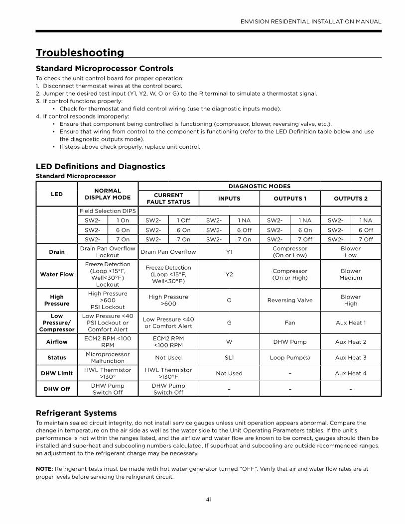
41
ENVISION RESIDENTIAL INSTALLATION MANUAL
Standard Microprocessor ControlsTo check the unit control board for proper operation:
Disconnect thermostat wires at the control board.1.
Jumper the desired test input (Y1, Y2, W, O or G) to the R terminal to simulate a thermostat signal.2.
If control functions properly:3.
Check for thermostat and field control wiring (use the diagnostic inputs mode).•
If control responds improperly:4.
Ensure that component being controlled is functioning (compressor, blower, reversing valve, etc.).•
Ensure that wiring from control to the component is functioning (refer to the LED Definition table below and use •
the diagnostic outputs mode).
If steps above check properly, replace unit control.•
Refrigerant Systems To maintain sealed circuit integrity, do not install service gauges unless unit operation appears abnormal. Compare the
change in temperature on the air side as well as the water side to the Unit Operating Parameters tables. If the unit’s
performance is not within the ranges listed, and the airflow and water flow are known to be correct, gauges should then be
installed and superheat and subcooling numbers calculated. If superheat and subcooling are outside recommended ranges,
an adjustment to the refrigerant charge may be necessary.
NOTE: Refrigerant tests must be made with hot water generator turned “OFF”. Verify that air and water flow rates are at
proper levels before servicing the refrigerant circuit.
LEDNORMAL
DISPLAY MODE
DIAGNOSTIC MODES
CURRENT FAULT STATUS
INPUTS OUTPUTS 1 OUTPUTS 2
Field Selection DIPS
SW2- 1 On SW2- 1 Off SW2- 1 NA SW2- 1 NA SW2- 1 NA
SW2- 6 On SW2- 6 On SW2- 6 Off SW2- 6 On SW2- 6 Off
SW2- 7 On SW2- 7 On SW2- 7 On SW2- 7 Off SW2- 7 Off
DrainDrain Pan Overflow
LockoutDrain Pan Overflow Y1
Compressor(On or Low)
Blower Low
Water Flow
Freeze Detection (Loop <15°F, Well<30°F)
Lockout
Freeze Detection (Loop <15°F, Well<30°F)
Y2Compressor(On or High)
Blower Medium
High Pressure
High Pressure >600
PSI Lockout
High Pressure >600
O Reversing ValveBlower High
Low Pressure/
Compressor
Low Pressure <40 PSI Lockout or Comfort Alert
Low Pressure <40 or Comfort Alert
G Fan Aux Heat 1
AirflowECM2 RPM <100
RPMECM2 RPM <100 RPM
W DHW Pump Aux Heat 2
StatusMicroprocessor
MalfunctionNot Used SL1 Loop Pump(s) Aux Heat 3
DHW LimitHWL Thermistor
>130°HWL Thermistor
>130°FNot Used – Aux Heat 4
DHW OffDHW Pump Switch Off
DHW Pump Switch Off
– – –
LED Definitions and DiagnosticsStandard Microprocessor
Troubleshooting

42
ENVISION RESIDENTIAL INSTALLATION MANUAL
Water Coil Maintenance1. Keep all air out of the water. An open loop system should be checked to ensure that the well head is not allowing air to
infiltrate the water line. Lines should always be airtight.
2. Keep the system under pressure at all times. It is recommended in open loop systems that the water control valve be
placed in the discharge line to prevent loss of pressure during off cycles. Closed loop systems must have positive static
pressure.
NOTE: On open loop systems, if the installation is in an area with a known high mineral content (125 PPM or greater) in
the water, it is best to establish with the owner a periodic maintenance schedule so the coil can be checked regularly.
Should periodic coil cleaning be necessary, use standard coil cleaning procedures which are compatible with either the
cupronickel or copper water lines. Generally, the more water flowing through the unit the less chance for scaling.
Other Maintenance Filters
Filters must be clean to obtain maximum performance. They should be inspected monthly under normal operating
conditions and be replaced when necessary. Units should never be operated without a filter.
Condensate Drain
In areas where airborne bacteria produce a slime in the drain pan, it may be necessary to treat chemically to minimize the
problem. The condensate drain can pick up lint and dirt, especially with dirty filters. Inspect twice a year to avoid the
possibility of overflow.
Blower Motors
ECM blower motors are equipped with sealed ball bearings and require no periodic oiling.
PSC blower motors should only be lubricated if dry operation is suspected.
Hot Water Generator Coil
See Water Coil Maintenance section above.
Air Coil
The air coil must be cleaned to obtain maximum performance. Check once a year under normal operating conditions and,
if dirty, brush or vacuum (with a brush attachment) clean. Care must be taken not to damage the aluminum fins while
cleaning.
Obtaining PartsWhen ordering service or replacement parts, refer to the model number and serial number of the unit as stamped on the
serial plate attached to the unit. If replacement parts are required, mention the date of installation of the unit and the date
of failure, along with an explanation of the malfunctions and a description of the replacement parts required.
In-Warranty Material ReturnMaterial may not be returned except by permission of authorized warranty personnel. Contact your local distributor for
warranty return authorization and assistance.
CAUTION: Fin edges are sharp.
Preventive Maintenance
Replacement Procedures

Product: Envision Residential
Type: Geothermal/Water Source Heat Pumps
Size: 2-6 Ton Single Speed
2-6 Ton Dual Capacity
Document: Installation Manual
Manufactured by
WaterFurnace International, Inc.
9000 Conservation Way
Fort Wayne, IN 46809
www.waterfurnace.com
© 2009 WaterFurnace International, Inc., 9000 Conservation Way, Fort Wayne, IN 46809-9794. WaterFurnace has a policy of continual product research and development and
reserves the right to change design and specifications without notice.
IM1000AN 12/09