environmental simulation of a spacecraft on a launchpad
TRANSCRIPT
GSFC· 2015
Environmental
Simulation of a
Spacecraft on a
Launchpad
Ron Behee
MSC Software
Shekhar Kanetkar
MSC Software

Introduction
• Present an example model of a Falcon 9
rocket with a spacecraft on the launch pad
• Show a method for realistic modeling of
the weather effects and solar loads on
aerospace hardware at any time, date and
location on the earth
• MSC Patran, Sinda and Thermica was
used in the example model
• Other thermal analyzers and orbital
heating codes could be used, but would
require some manual work to incorporate
the data from the Department of Energy
weather files into the model. This is done
automatically with Environment Simulation
Module that is part of MSC Patran 2013 or
later.
2TFAWS 2015 – August 3-7, 2015 – Silver Spring, MD

Solar Energy 101
Solar Energy Fundamentals
3TFAWS 2015 – August 3-7, 2015 – Silver Spring, MD

DNI and DHI
• DNI (direct normal irradiance)
– This is the directional component, the beam component
• DHI (diffuse horizontal irradiance)
– This part comes from the entire sky, due to scattering in the atmosphere
DHI
DHI
DHI
DNI
TFAWS 2015 – August 3-7, 2015 – Silver Spring, MD 4

GHI
• GHI (Global Horizontal Irradiance)
– GHI is a sum of the DNI and DHI
according to:
– GHI = DHI + DNI * cos (Z)
• Where Z is the angle from the normal of
the earth to the Sun
DHI
DHI
DHI
DNI
TFAWS 2015 – August 3-7, 2015 – Silver Spring, MD 5

GHI for Different Zenith Angles
• GHI = DHI + DNI * cos (Z)Where Z is the angle from the normal of the earth to the Sun
When the sun is just
coming up with a zenith
angle of 90, the cosine of
90 deg = 0.0, so the GHI
is just the DHI
DNIDHI
DHI
DHI
When the sun is directly
overhead with a zenith angle of
zero, the cosine of 0 deg = 1.0, so
GHI is the sum of DHI and DNI
DNI
TFAWS 2015 – August 3-7, 2015 – Silver Spring, MD 6

Weather Data
What is TMY3 data and why do I need it!
7TFAWS 2015 – August 3-7, 2015 – Silver Spring, MD

Typical Meteorological Year (TMY)
• A reasonably sized annual (1 year) set of data
• Hourly meteorological values that typify conditions at a specific
location. This data includes DHI, DNI, GHI, air temperature/humidity
deep ground temperature and much more.
• Averaged over a long period of time, such as 30 years to give typical
values
• Their intended use is for computer simulations of solar energy
conversion systems and building systems to facilitate performance
comparisons of different system types, configurations, and locations
in the United States and its territories.
• Not designed to provide meteorological extremes but represents a
year of typical climatic conditions for a location.
8TFAWS 2015 – August 3-7, 2015 – Silver Spring, MD
A typical meteorological year (TMY) data set provides designers
with the following:

TMY3 Data
• TMY3 is the latest version of the TMY data updated in 2008.
• EPW – Energy Plus Weather (EPW) contain data from over 2000
locations around the world. TMY3 is the US standard. Other
countries use different formats but are all saved in a EPW format
and contain similar data.
• Because TMY3 data sets represent typical rather than extreme
conditions, they are not suited for designing systems to meet the
worst-case conditions occurring at a location. The Design Day
feature in our software products is used for these worst-case
conditions.
• Environment Simulation Module (ESM) in Patran directly reads the
EPW files and computes or extracts data that is written automatically
into Patran for use in thermal models.
• For those who don’t have Patran, downloadable readers that can
access the data from EPW files are available on the web site along
with the data which can be manually entered into other software.
9TFAWS 2015 – August 3-7, 2015 – Silver Spring, MD

Department of Energy Weather Database
TFAWS 2015 – August 3-7, 2015 10
Search for keywords EPW weather data

DNI and DHI for Two Locations on May 15,16
11TFAWS 2015 – August 3-7, 2015 – Silver Spring, MD
Phoenix Arizona
DNI 950w/sqm
DHI 150w/sqm
Fairbanks Alaska
DNI 750w/sqm
DHI 300w/sqm

Methods for Using Weather Data
TFAWS 2015 – August 3-7, 2015 – Silver Spring, MD 12
• Hourly Query - Pick a Day or
range of days and the start and
finish hour
• Design Day Query - Create worst
case weather based on the users
criteria
• Manually Setup – Use any tables
desired using data from sources
such as Mil Handbook 310

Design Day
TFAWS 2015 – August 3-7, 2015 13
Comparison Max DNI to Max DHI at 10AM
Max DHI
Diffuse Horizontal Irradiance
27.9 C to 63.2 C
Max DNI
Direct Normal Irradiance
12.2 C to 87.3 C

Date Range Query July 1-10
TFAWS 2015 – August 3-7, 2015 14

Date Range Query July 1-10
TFAWS 2015 – August 3-7, 2015 15
KSC’s Shuttle Landing Facility
DHI and DNI Plot for 10 Days

Design Day Query – July 1-31
TFAWS 2015 – August 3-7, 2015 16

Design Day Query – July 1-31
TFAWS 2015 – August 3-7, 2015 17
KSC’s Shuttle Landing Facility
DHI and DNI Plot for Design Day

Design Day to Date Range Query
TFAWS 2015 – August 3-7, 2015 18

Environment Simulation Loads
19
Ambient
Temperature
Convection
Wind speed and
Direction
From weather
database
Sky Temperature
Radiation
Computed directly from
weather database
Surface
Material Below Surface
Ground models
Built-in or User
Defined
Diffuse Flux from
weather database
Direct Flux form weather
Database
The following data is read from the weather
and is transient hourly data

Ground Models
Far Field Ground (FFG) and Near Field
Ground (NFG) Models
20TFAWS 2015 – August 3-7, 2015 – Silver Spring, MD

Ground Modeling
• FFG = Far field ground - always present in model
• NFG = Near field ground - added by user if needed
When creating a thermal model using the Environment Simulation
Module (ESM) feature in Patran, the ground needs to be considered. Two
types of ground models can be used.
TFAWS 2015 – August 3-7, 2015 – Silver Spring, MD 24
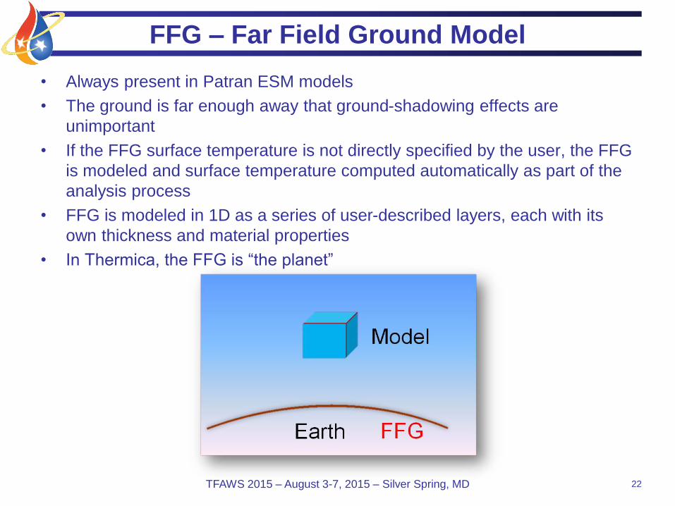
FFG – Far Field Ground Model
• Always present in Patran ESM models
• The ground is far enough away that ground-shadowing effects are
unimportant
• If the FFG surface temperature is not directly specified by the user, the FFG
is modeled and surface temperature computed automatically as part of the
analysis process
• FFG is modeled in 1D as a series of user-described layers, each with its
own thickness and material properties
• In Thermica, the FFG is “the planet”
22TFAWS 2015 – August 3-7, 2015 – Silver Spring, MD

NFG – Near Field Ground Model
• NFG model is optional and only present if user geometrically models it. It is In addition
to the FFG which is always present
• NFG Model Is a 3D slab of ground with one or more layers – typically about 2 meters
deep.
– Bottom of the NFG model is usually set to the deep ground temperature from the EPW data.
Yearly variations of the deep ground temperatures is small enough and has little affect on the
surface temperature so can just use a constant value.
– Model can be embedded into the ground if desired
• Typically NFG and FFG layers and surface boundary conditions are the same, but this
is not required
23TFAWS 2015 – August 3-7, 2015 – Silver Spring, MD

Patran Models with and without a NFG Model
Patran – FFG only Patran with NFG
Thermica FFG only Thermica with NFG
The FFG (i.e. the planet) is always present
TFAWS 2015 – August 3-7, 2015 – Silver Spring, MD 27

Affects of a NFG Model
• NFG modeling accounts for shadows cast on the ground by the model and
spatial varying surface properties which may cause the following:
– Temperature variations along the surface
– Ground-reflected solar radiation variations
25TFAWS 2015 – August 3-7, 2015 – Silver Spring, MD
Clay
Moist soil Concrete Moist soil
BuildingGrass surface
Landscape
rocks

When is it Important to Add a NFG Model
• When a NFG model is needed
– Model is close enough to the ground for shadowing effects or non uniformity of the ground
model become important
– Model is embedded in the ground
• When you can ignore a NFG model
– Spatially uniform ground temperature and reflected solar radiation is an acceptable
assumption
– NOTE: the bottom of the model will be illuminated from below by ground reflected solar
radiation (albedo), even if Z=0.0!
– MODELING TRICK: If model is flat-bottom, low absorptivity value on bottom prevent albedo
from below, but more complex shapes may require modeling the NFG
• Conclusions
– The NFG is often not needed
– Even if ultimately used in the model your first model should exclude it
• To help understand the relative importance of ground shadowing to the final answers.
• To evaluate if the NFG computation burden is justified by the change in results, to be judged case by
case
26TFAWS 2015 – August 3-7, 2015 – Silver Spring, MD

FFG Model Setup in the Patran ESM
TFAWS 2015 – August 3-7, 2015 – Silver Spring, MD 27

Examples With and Without a NFG Model
TFAWS 2015 – August 3-7, 2015 – Silver Spring, MD 28
No local ground model With local ground model

Example Model
Model of Falcon 9 rocket on a launch pad is
used to show the analysis process.
Note: This model is simplified and does not
represents actual hardware
29

Example Model
30TFAWS 2015 – August 3-7, 2015 – Silver Spring, MD

Patran Model
31TFAWS 2015 – August 3-7, 2015 – Silver Spring, MD
Simplified model was build to illustrate the method and did not use realistic materials

Temperature Results
TFAWS 2015 – August 3-7, 2015 – Silver Spring, MD 32

Temperature for 24 Hours Starting at 12:00AM
TFAWS 2015 – August 3-7, 2015 33

Summary
• EPW files with typical meteorological year data is useful
for realistic thermal modeling of aerospace hardware in
the sun. Other data can also be extracted or computed
such as air temperature, wind speed, sky temperature
and deep ground temperature.
• Mil Spec’s maybe be required, but may create unrealistic
results. Engineers can add reliability and confidence to
their designs using EPW data.
• These techniques can be used with any full featured
thermal analysis software, but require manual setup.
• MSC’s Environment Simulation Model makes it easy to
utilize this data and also allow creation of worst hot/cold
cases to be computed from the data
34TFAWS 2015 – August 3-7, 2015