environmental science electronic supplementary …china, hefei 230026, china; djiangsu collaborative...
TRANSCRIPT

S1
Electronic Supplementary Information (ESI) for Energy & Environmental Science
Synergistic effect of well-defined dual site boosting oxygen reduction reaction
Jing Wang,‡a Liu Wei,‡c Gan Luo,d Zhijun Li,a Chao Zhao,a Haoran Zhang,a Mengzhao Zhu,a Qian Xu,c Xiaoqian Wang,a Changming Zhao,a Yunteng Qu,a Zhengkun Yang,a Tao Yao,c Yafei Li,d Yue Lin,*e Yuen Wu,*a Yadong Lib
aDepartment of Chemistry, Hefei National Laboratory for Physical Sciences at the
Microscale, iChEM (Collaborative Innovation Center of Chemistry for Energy
Materials), University of Science and Technology of China, Hefei 230026, China;
bDepartment of Chemistry, Tsinghua University, Beijing 100084, China;
cNational Synchrotron Radiation Laboratory, University of Science and Technology of
China, Hefei 230026, China;
dJiangsu Collaborative Innovation Centre of Biomedical Functional Materials, School of Chemistry and Materials Science, Nanjing Normal University, Nanjing, 210023, China.eHefei National Laboratory for Physical Sciences at the Microscale, University of Science and Technology of China, Hefei 230026, China.
‡ These authors contributed equally.
Corresponding authors: Y. Wu ([email protected]), Y. Lin ([email protected])
Electronic Supplementary Material (ESI) for Energy & Environmental Science.This journal is © The Royal Society of Chemistry 2018

S2
1.Material Synthesis and Characterization:
Chemicals:
Analytical grade Zinc nitrate hexahydrate (Zn(NO3)2·6H2O), Cobalt nitrate hexahydrate (Co(NO3)2·6H2O), 2-methylimidazole (MeIM), Ferric chloride (FeCl3·6H2O), Cobalt chloride (CoCl2·6H2O), Hexane, Methanol were obtained from Shanghai Chemical Reagents, China. The commercial Pt/C catalyst is 20 % by wt. of ~3 nm Pt nanoparticles on Vulcan XC-72 carbon support. Nafion was acquired from Sigma-Aldrich. The commercial N doped carbon nanotubes (CNT-C, inner diameter: 5-12 nm, external diameter: 30-50 nm, length: 10-30 μm) was acquired from Aladdin. De-ionized water with the specific resistance of 18.25 MΩ cm was obtained by reversed osmosis followed by ion-exchange and filtration (Clean Water Treatmeny Co., Ltd., Hefei). All chemicals were from commercial and used without further purification.
Experimental Section:
Synthesis of Zn1Co1-BMOF.
In a typical procedure, Co(NO3)2·6H2O (0.546 g) and Zn(NO3)2·6H2O (0.558 g) were dissolved in 15 mL of methanol, 2-methylimidazole (0.616 g) in 15 mL of methanol was subsequently injected into the above solution under vigorously stirring for 6 h at room temperature. The as-obtained precipitates were centrifuged and washed with methanol for several times and dried in vacuum at 60 oC for overnight.
Synthesis of (Fe,Co)/CNT.
Typically, Zn1Co1-BMOF (100 mg) was dispersed in 13 mL of hexane by sonication for 1 h at room temperature. 50 μL FeCl3·6H2O (150 mg mL-1) was added dropwisely to the above solution under ultrasound for 10 min. The vial containing the slurry was stirred at room temperature for 2 h. The impregnated Zn1Co1-BMOF sample was centrifuged and dried in vacuum at 60 oC for overnight. The powder of the impregnated Zn1Co1-BMOF sample was placed in a tube furnace and then heated to the desired temperature (900 oC) for 2 h with a heating rate of 5 oC min-1 under a flowing of N2 before cooled to room temperature naturally to give the (Fe,Co)/CNT. The ICP result showed the metal contents for Fe and Co in (Fe,Co)/CNT with Fe-Co dual site were 1.21 % and 1.13 %, respectively.
Synthesis of FeCo NPs/CNT.

S3
The synthesis of FeCo alloy nanoparticles in N doped carbon nanotubes (FeCo NPs/CNT) was similar to (Fe,Co)/CNT, except for increasing the concentration of FeCl3·6H2O from 150 mg mL-
1 to 200 mg mL-1.
Synthesis of Fe/CNT-C.
The single Fe atoms on N doped carbon nanotubes (Fe/CNT-C) was prepared as a reference.. The commercial N doped carbon nanotubes were used as the support to stabilize the single Fe atoms. CNT-C (20 mg) was dispersed in 10 mL of H2O by sonication for 1 h at room temperature. FeCl3·6H2O (1 mg) was added to the above solution under vigorously stirring for 2 h. The impregnated CNT-C sample was centrifuged and dried in vacuum at 60 oC for overnight. The powder of the impregnated CNT-C sample was placed in a tube furnace and then heated to the desired temperature (900 oC) for 2 h with a heating rate of 5 oC min-1 under a flowing of N2 before cooled to room temperature naturally to give the Fe/CNT-C.
Synthesis of Co/CNT-C.
Single Co atoms on N doped carbon nanotubes (Co/CNT-C) can be easily obtained by the above method, replacing FeCl3·6H2O with CoCl2·6H2O.
Synthesis of FeCo NPs/CNT-C.
FeCo alloy nanoparticles on N doped carbon nanotubes (FeCo NPs/CNT-C) can be prepared by the same method, adding FeCl3·6H2O (2 mg) and CoCl2·6H2O (2 mg) into the solution of CNT-C.
Synthesis of FeCo clusters/CNT-C.
FeCo clusters on N doped carbon nanotubes (FeCo clusters/CNT-C) was synthesized by acid leaching of FeCo NPs/CNT-C for overnight.
Characterization:
Powder X-ray diffraction patterns of samples were recorded using a Rigaku Miniflex-600 with Cu Kα radiation (Cu Kα, λ = 0.15406 nm, 40 kV and 15 mA). The morphologies were characterized by TEM (Hitachi-7700, 100KV). The high-resolution TEM, HAADF-STEM images the corresponding Electron energy-loss spectroscopy were recorded by a FEI Tecnai G2 F20 S-Twin high-resolution transmission electron microscope working at 200 kV and on a JEOL JEM-ARM200F TEM/STEM with a spherical aberration corrector working at 300 kV. The SEM was carried out by a JSM-6700F SEM. Nitrogen sorption measurement was conducted using a Micromeritics ASAP 2020 system at 77 K. Photoemission spectroscopy experiments (XPS) were performed at the Catalysis and Surface Science End station at the BL11U beamline of National

S4
Synchrotron Radiation Laboratory (NSRL) in Hefei, China. Fourier transform infrared spectra (FT-IR) of the samples were recorded on a VECTOR-22FT-IR spectrometer over potassium bromide pellet. Raman scattering spectra were recorded with a Renishaw System 2000 spectrometer using the 514.5 nm line of Ar+ for excitation. Elemental analysis of Fe and Co in the solid samples was detected by an Optima 7300 DV inductively coupled plasma atomic emission spectrometer (ICP-AES). XAFS measurement and data analysis:XAFS spectra at the Co K-edge (7709 eV) and Fe K-edge (7112 eV) were measured at the beamline 1W1B station of the Beijing Synchrotron Radiation Facility, China. The Co K-edge XANES data were recorded in a fluorescence mode. Co foil, CoPc were used as references. The Fe K-edge XANES data were recorded in a fluorescence mode. Fe foil, FePc, Fe3O4 were used as references. The storage ring was working at the energy of 2.5 GeV with an average electron current of 250 mA. The hard X-ray was monochromatized with Si (111) double-crystals. The acquired EXAFS data were extracted and processed according to the standard procedures using the ATHENA module implemented in the IFEFFIT software packages. The k3-weighted EXAFS spectra were obtained by subtracting the post-edge background from the overall absorption and then normalizing with respect to the edge-jump step. Subsequently, k3-weighted χ(k) data in the k-space ranging from 2.5–11.2 Å−1 were Fourier transformed to real (R) space using a hanning windows (dK = 1.0 Å−1) to separate the EXAFS contributions from different coordination shells.
2.Electrochemical Measurements:
Electrochemical measurements for ORR.
All catalysts were prepared by mixing 10 mg of the catalysts in 1 mL of solution containing 480 μL of ethanol, 480 μL of H2O and 40 μL of 5% Nafion solution, followed by ultrasonication for 20 min to form homogeneous catalysts inks. Commercial 20 % wt Pt/C sample was prepared by dispersing 4 mg of the catalyst in 1 mL of solution. Next, a certain volume of the catalyst ink was carefully dropped onto the polished glassy carbon rotating disk electrode (RDE) or rotating ring disk electrode (RRDE) to yield a desirable catalyst loading. For RDE and RRDE test, the absolute mass loading was 0.5102 mg cm-2 of nonprecious catalysts and the loading for Pt/C (w.t. 20%) was 0.102 mg cm-2 in 0.1 M KOH.
Electrochemical measurements were carried out in a three-electrode system on a CHI 760E electrochemical workstation (Shanghai Chenhua, China) in 0.1 M KOH electrolyte. A glassy carbon (GC) RDE of 5 mm in diameter coated with the catalyst ink was served as the working electrode, a Ag/AgCl and Pt wire were used as reference and counter electrode. Prior to the measurement, a N2/O2 flow was used through the electrolyte in the cell for 30 min to saturate it with N2/O2. The electrochemical experiments were conducted in O2-saturated 0.1 M KOH for the oxygen reduction reaction at room temperature. The RDE tests were measured at various rotating speed from 900 to 2500 rpm with a sweep rate of 10 mV s-1. The cyclic voltammetry (CV) experiments were cycled in N2/O2-saturated 0.1 M KOH electrolyte solutions with a scan rate of 50 mV s-1. For the ORR at a RDE, the electron transfer number (n) and kinetic current density (JK) were calculated from the Koutecky-Levich equation:

S5
1𝐽
=1𝐽𝐿
+1𝐽𝐾
=1
𝐵𝜔12
+1𝐽𝐾
𝐵 = 0.62𝑛𝐹𝐶0𝐷230𝑉
‒16
where J is the measured current density, JK and JL are the kinetic and limiting current densities, ω is the angular velocity of the disk, n is the electron transfer number, F is the Faraday constant (96485 C mol-1), C0 is the bulk concentration of O2 (1.2 × 10⁻⁶ mol cm-3), D0 is the diffusion coefficient of O2 (1.9 × 10⁻⁵ cm2 s-1), and V is the kinematic viscosity of the electrolyte (0.01 cm2 s-1).
For RRDE tests, a computer-controlled CHI 760E electrochemical workstation was employed and the disk electrode was scanned catholically at a rate of 10 mV s-1 and the ring electrode potential was set to 1.20 V vs. RHE. The hydrogen peroxide yield (H2O2 %) and the electron transfer number (n) were determined by the following equations:
𝐻2𝑂2 (%) = 200 ×
𝐼𝑟
𝑁
𝐼𝑑 +𝐼𝑟
𝑁
𝑛 = 4 ×𝐼𝑑
𝐼𝑑 +𝐼𝑟
𝑁
Where Id is the disk current, Ir is the ring current, and N = 0.4 is the current collection efficiency of the Pt ring.
The accelerated durability tests of the catalysts were performed in the O2-saturated 0.1 M KOH electrolyte at room temperature by applying potential cycling between 1.0 and 0.6 V vs. RHE at a sweep rate of 50 mV s-1 for 10,000 cycles.
Turnover frequency (TOF) of the Fe/CNT-C, Co/CNT-C and (FeCo)/CNT were calculated based on the mole number of active Fe single sites, Co single sites and Fe-Co dual sites, respectively. The TOF values were calculated using the equation:
𝑇𝑂𝐹 =𝐽 × 𝑎
4 × 𝑚 × 𝐹
Where J is the measured current density at 0.9 V, a is the surface area of the electrode (0.196 cm2 for the GC disk electrode), 4 is the number of electrons transferred during O2 reduction, m is the mole number of active Fe single sites, Co single sites and Fe-Co dual sites on the electrode, and F is the Faraday constant (F = 96,485 C mol-1).
Electrochemical measurements for Zn-air battery.

S6
Primary Zn-air batteries were tested in a home-built electrochemical cell. For catalyst ink preparation, 10 mg of the (Fe,Co)/CNT was ultrasonically dispersed in 1 mL of solution containing 480 μL of ethanol, 480 μL of H2O and 40 μL of 5% Nafion solution. The homogeneous ink (0.1 mL) was loaded on carbon fiber paper (1 cm2), with a loading density of 1mg cm-2,as the air cathode, and Zn foil was used as the anode in O2-saturated 6M KOH solution. While, commercial 20 % wt Pt/C sample was prepared by dispersing 4 mg of the catalyst in 1 mL of solution, with a loading of 0.4 mg cm-2. All data were collected from the as-fabricated cell with a CHI 760E electrochemical workstation (Shanghai Chenhua, China) at room temperature.
3. Computational MethodsSpin-unrestricted DFT calculations were performed in the VASP1,2 within the projector-
augmented plane wave approach3,4 and GGA-PBE functional.5The plane-wave set with a cutoff energy of 400 eV were adopted in all computations. Calculations reached Convergence criterions until energy and forces dropped below 10-5 eV and 0.03 eV/Å, respectively. Figure 3E shows the geometrical structure of the (Fe,Co)/CNT unit where Fe-Co/N6-moiety embedded in graphene (50 C atoms). Similar to (Fe,Co)/CNT, Co SAs/N-C unit embedding Co/N4-moiety into carbon matrix (54 C atoms). The vacuum space of 12 Å at least was selected to remove the virtual image interaction. The 3×3×1 k-point samplings were chosen for all computations.
The free energies (G) of adsorbates and molecules can be calculated by: G = EDFT + ZPE TS, where EDFT, ZPE, and S represent ground state energy, zero point energy, and entropy, respectively. For adsorbates, ZPE and S are obtained by vibrational frequencies calculations with harmonic approximation, whereas for molecules these values are taken from the NIST database.6 The solvent effect on OOH* and OH* is included using the Poissson-Boltzmann implicit solavtion model.7
O2 activation generally follows one of the two mechanisms, namely associative and dissociative pathways. Fe-Co dual site perfers associative ORR mechanism, since there are no spontaneous dissociation of O2 during structure optimization. Therefore, in alkaline medium, the ORR process on (Fe,Co)/CNT may involve the following steps (4-electron pathway):
O2 + H2O + e + * → OOH* + OH (S1)
OOH* + e → O* + OH (S2)
O* + H2O + e→ OH* + OH (S3)
OH* + e → * + OH (S4)
Moreover, the 2-electron pathway can be expressed as:
O2 + H2O + e + * → OOH* + OH (S5)
OOH* + e → OOH (S6)
The computational hydrogen electrode (CHE) model8 is used to account for the effects of electrode potential (U) and pH on the free energy of the electron transfer steps: ΔGU = eU and

S7
ΔGpH = kBTln10 × pH. The theoretical limiting potential (Ulim) for a given catalyst is determined by the maximum free energy change of the electronic steps (ΔGmax): Ulim = ΔGmax/e. Note that the free energy diagram of ORR shown in present work has performed a potential correction vs. RHE.
4. Supporting Figures and Tables:
Fig. S1. (A-D)TEM images of the products obtained in different temperatures: (A) 800 oC, 0 h,
(B) 900 oC, 0 h, (C) 900 oC, 0.5 h, (D) 900 oC, 2 h.

S8
Fig. S2: (A) TEM image, (B) HAADF-STEM image of FeCo NPs/CNT. (C) HAADF-STEM image and electron diffraction pattern of FeCo NPs in FeCo NPs/CNT. (E) Corresponding EELS mapping images of Fe, Co, C, N.

S9
Fig. S3. (A) XRD pattern of (Fe,Co)/CNT. (B) XRD patterns of Zn1Co1-BMOF and
Zn1Co1-BMOF+FeCl3.

S10
Fig. S4. Raman spectrum for (Fe,Co)/CNT.
S11
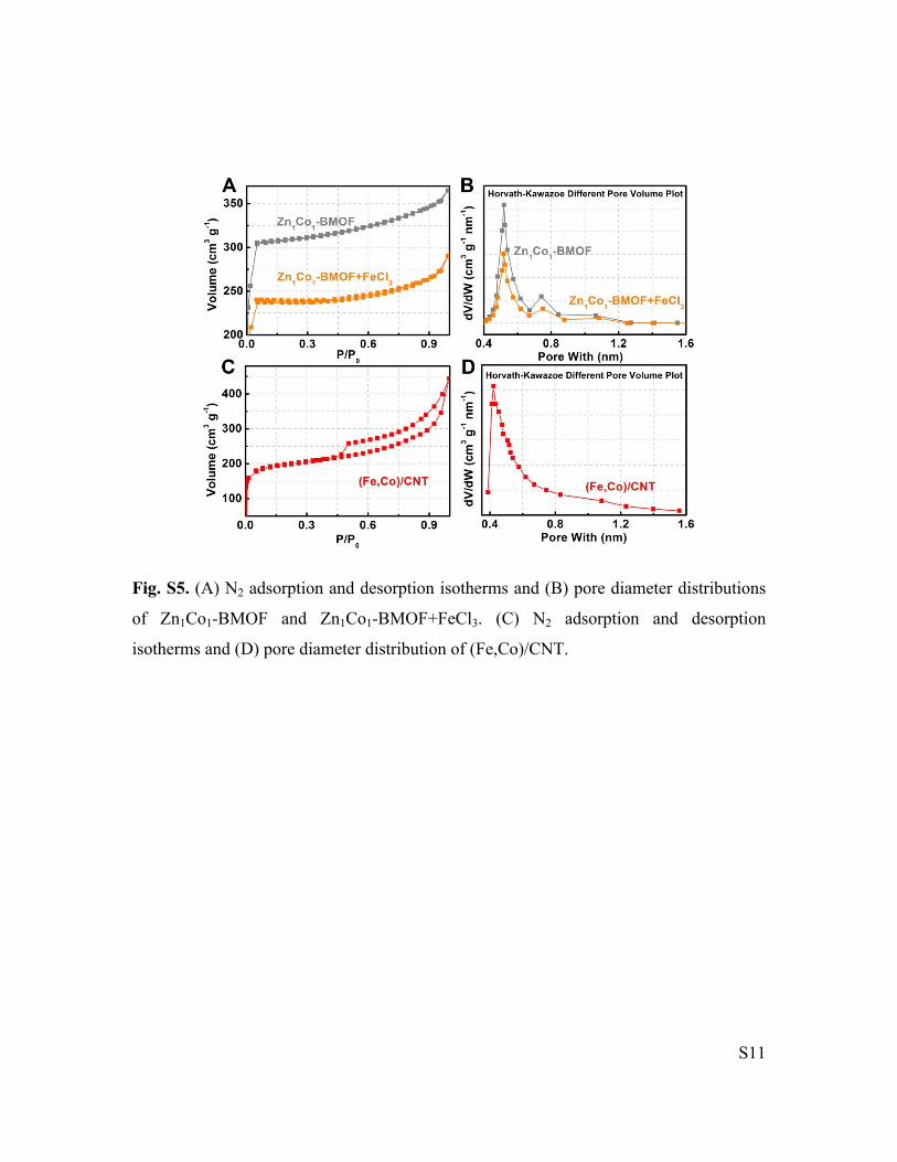
Fig. S5. (A) N2 adsorption and desorption isotherms and (B) pore diameter distributions
of Zn1Co1-BMOF and Zn1Co1-BMOF+FeCl3. (C) N2 adsorption and desorption
isotherms and (D) pore diameter distribution of (Fe,Co)/CNT.
S12
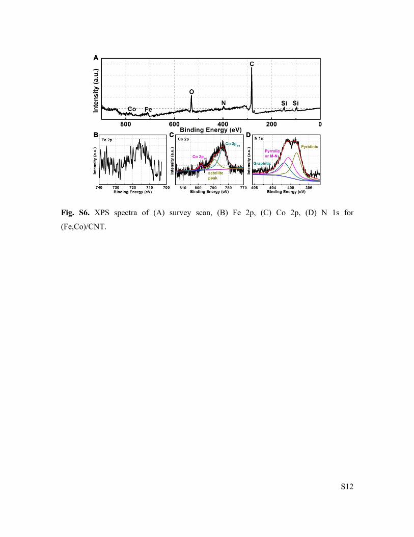
Fig. S6. XPS spectra of (A) survey scan, (B) Fe 2p, (C) Co 2p, (D) N 1s for
(Fe,Co)/CNT.

S13
Fig. S7. (A) Fe L-edge, (B) Co L-edge XANES spectra of (Fe,Co)/CNT. (C) C K-edge,
and (D) N K-edge XAS spectra of (Fe,Co)/CNT.

S14
Fig. S8. (A) Fe K-edge XANES spectra, (B) Fourier transformed (FT) k3-weighted χ(k)-
function of the EXAFS spectra for Fe K-edge of (Fe,Co)/CNT, FeCo NPs/CNT-C and
FeCo NPs/CNT.

S15
Fig. S9. (A) Co K-edge XANES spectra of (Fe,Co)/CNT. (B) Fourier transformed (FT)
k3-weighted χ(k)-function of the EXAFS spectra for Co K-edge of (Fe,Co)/CNT. (C,D)
The corresponding Co K-edge EXAFS fitting curves of (Fe,Co)/CNT.

S16
Fig. S10. The corresponding Fe K-edge EXAFS fitting curves of (Fe,Co)/CNT.

S17
Fig. S11: (A) The Fe K-edge (B) Co K-edge EXAFS fitting curves of (Fe,Co)/CNT.

S18
Fig. S12: (A) TEM image of FeCo clusters/CNT-C. (B) RDE polarization curves of FeCo NPs/CNT-C, FeCo clusters/CNT-C, and (Fe,Co)/CNT in O2-saturated 0.1 M KOH with a sweep rate of 10 mV s-1 and a rotation rate of 1600 rpm.
S19
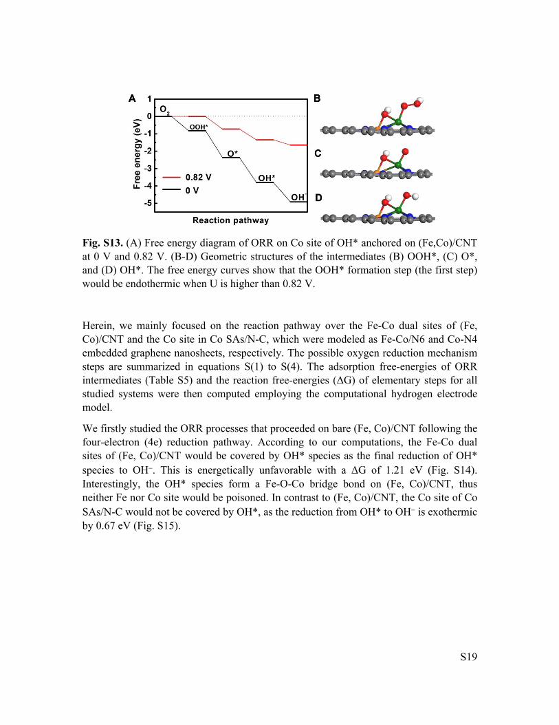
Fig. S13. (A) Free energy diagram of ORR on Co site of OH* anchored on (Fe,Co)/CNT at 0 V and 0.82 V. (B-D) Geometric structures of the intermediates (B) OOH*, (C) O*, and (D) OH*. The free energy curves show that the OOH* formation step (the first step) would be endothermic when U is higher than 0.82 V.
Herein, we mainly focused on the reaction pathway over the Fe-Co dual sites of (Fe, Co)/CNT and the Co site in Co SAs/N-C, which were modeled as Fe-Co/N6 and Co-N4 embedded graphene nanosheets, respectively. The possible oxygen reduction mechanism steps are summarized in equations S(1) to S(4). The adsorption free-energies of ORR intermediates (Table S5) and the reaction free-energies (ΔG) of elementary steps for all studied systems were then computed employing the computational hydrogen electrode model.
We firstly studied the ORR processes that proceeded on bare (Fe, Co)/CNT following the four-electron (4e) reduction pathway. According to our computations, the Fe-Co dual sites of (Fe, Co)/CNT would be covered by OH* species as the final reduction of OH* species to OH. This is energetically unfavorable with a ΔG of 1.21 eV (Fig. S14). Interestingly, the OH* species form a Fe-O-Co bridge bond on (Fe, Co)/CNT, thus neither Fe nor Co site would be poisoned. In contrast to (Fe, Co)/CNT, the Co site of Co SAs/N-C would not be covered by OH*, as the reduction from OH* to OH is exothermic by 0.67 eV (Fig. S15).

S20
Fig. S14. (A) Free energy diagram for ORR on Fe-Co dual sites of (Fe,Co)/CNT. (B-D) Geometric structures of the intermediates (B) OOH*, (C) O*, and (D) OH*. The free energy curves show that the OH* removal step (the last step) is endothermic by 1.21 eV, implying Fe-Co bridge site of (Fe,Co)/CNT is occupied by OH*.
S21
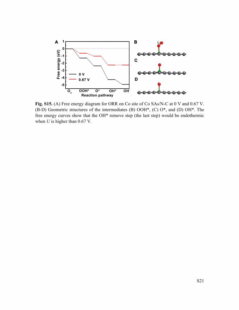
Fig. S15. (A) Free energy diagram for ORR on Co site of Co SAs/N-C at 0 V and 0.67 V. (B-D) Geometric structures of the intermediates (B) OOH*, (C) O*, and (D) OH*. The free energy curves show that the OH* remove step (the last step) would be endothermic when U is higher than 0.67 V.

S22
Fig. S16. The linear relationship (y=x+2.94) between ∆GOOH* and ∆GOH* in which Fe*, Co*, Co-SAs are Fe, Co sites on OH* saturated (Fe,Co)/CNT and Co sites on bare Co SAs/N-C.

S23
Fig. S17. SEM of Zn1Co1-BMOF.

S24
Fig. S18: TEM images of CNT-C (A), Co/CNT-C (B), Fe/CNT-C (C), FeCo NPs/CNT-C (D).

S25
Table S1. EXAFS data fitting results of (Fe,Co)/CNT.
Sample Edge Path N R(Å) 2 (10-3Å2)
E0 (eV)
R-factor
Fe-N1 2.2 1.98 3.9 -3.5
Fe-N2 1.0 2.05 3.9 -3.5Fe
Fe-Co 0.8 2.51 7.4 -4.0
0.007
Co-N1 2.1 1.90 4.4 -6.2
Co-N2 1.0 2.05 4.4 -6.2
(Fe,Co)/CNT
Co
Co-Fe 0.6 2.56 10.7 9.9
0.007
N, coordination number; R, distance between absorber and backscatter atoms; 2, the Debye-Waller factor value; E0 (eV), inner potential correction accounts for the difference in the inner potential between the sample and the reference compound.
S26
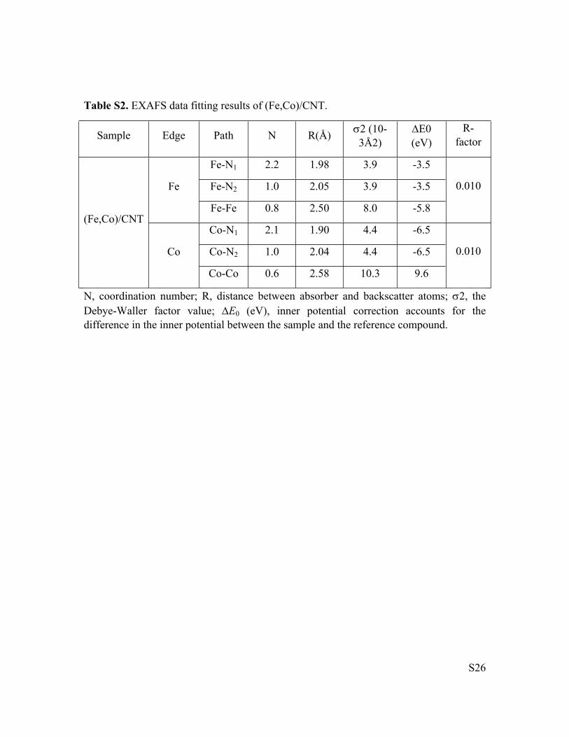
Table S2. EXAFS data fitting results of (Fe,Co)/CNT.
Sample Edge Path N R(Å) 2 (10-3Å2)
E0 (eV)
R-factor
Fe-N1 2.2 1.98 3.9 -3.5
Fe-N2 1.0 2.05 3.9 -3.5Fe
Fe-Fe 0.8 2.50 8.0 -5.8
0.010
Co-N1 2.1 1.90 4.4 -6.5
Co-N2 1.0 2.04 4.4 -6.5
(Fe,Co)/CNT
Co
Co-Co 0.6 2.58 10.3 9.6
0.010
N, coordination number; R, distance between absorber and backscatter atoms; 2, the Debye-Waller factor value; E0 (eV), inner potential correction accounts for the difference in the inner potential between the sample and the reference compound.

S27
Table S3 Comparison of ORR activities among different nonprecious catalysts in 0.1 M
KOH.
CatalystsScan rate
(mV s-1)
Rotation rate
(rpm)
Onset potential
(V vs. RHE)
Half-wave
potential (V vs. RHE)
Current density at 0.9 V (vs. RHE mA cm-2)
Ref.
(Fe,Co)/CNT 10 1600 1.15 0.954 4.12This work
Fe/N/C 5 900 ~1.10 0.930 ~2.30 9
FePc-Py-CNT 10 - ~0.99 0.915 ~3.30 10
Fe-ISAs/CN 10 1600 ~1.00 0.900 ~2.90 11
Fe@C-FeNC-2 10 1600 ~1.04 0.899 ~2.60 12
Co SAs/N-C(900) 10 1600 0.98 0.881 ~1.70 13
Fe-N-SCCFs 10 1600 1.03 0.883 ~2.20 14
CoO/NCNT 5 1600 0.93 0.860 ~0.10 15
NCNTFs 10 1600 ~0.98 0.870 ~1.04 16
P-CNCo-20 20 1600 0.93 0.850 ~0.06 17
NHPC-900-1000 10 1600 0.96 0.840 ~1.00 18
Cal-CoZIF-VXC72 5 1600 ~0.94 0.840 ~0.60 19
Co-NC 5 1600 ~0.92 0.830 ~0.40 20
CoOx NPs/BNG - 1600 0.95 0.805 ~0.60 21

S28
Table S4 The performance of Zn-air batteries of nonprecious catalysts in 6 M KOH.
CatalystCatalyst loading
(mg cm-2)
Open-circuit
Voltage (V)
Maximum power density
(mW cm-2)
Current density @ 1.0 V (mA
cm-2)
Ref
(Fe,Co)/CNT 1total 1.63 260 180This work
Co@NG-acid 1 ~1.40 350 250 22
CoO/N-CNT 1 ~1.40 265 200 23
Pyrolyzed FeCo-EDA (FeCo-N-C) 1.5 - 232 150 24
Fe@N-C-700 2.2 1.40 220 157 25
CuFe - - 212 ~94 26
P,S-CNS - 1.51 198 ~75 27
N-doped porous carbon nanfibers 2 - 194 150 28
Mn3O4/ketjenblack - - 190 120 29
Fe-N-MC 1.2 - ~186 ~107 30
NCNF-1000 2 1.48 185 ~119 31
Co4N/CNW/CC 1 1.40 174 ~71 32
1100-CNS-4 2 1.49 151 ~71 33
NiFe@NCx 1 - ~82 ~69 34
NPMC-1000 0.5 1.48 55 ~30 35
2DBN-800 ~1.0 1.40 14.6 ~11 36

S29
Table S5. The adsorption free-energies of ORR intermediates on different active sites of (Fe,Co)/CNT and Co SAs/N-C.
Adsorbed Sites ∆GOOH* (eV) ∆GO* (eV) ∆GOH* (eV)
Fe-Co dual sites 0.47 -0.57 -1.21
Fe on OH* anchored (Fe,Co)/CNT 3.92 2.33 0.99
Co on OH* anchored (Fe,Co)/CNT 4.10 2.56 1.12
Co on Co SAs/N-C 3.64 2.57 0.67
S30
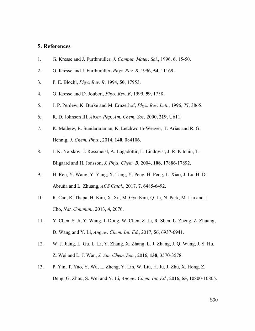
5. References
1. G. Kresse and J. Furthmüller, J. Comput. Mater. Sci., 1996, 6, 15-50.
2. G. Kresse and J. Furthmüller, Phys. Rev. B, 1996, 54, 11169.
3. P. E. Blöchl, Phys. Rev. B, 1994, 50, 17953.
4. G. Kresse and D. Joubert, Phys. Rev. B, 1999, 59, 1758.
5. J. P. Perdew, K. Burke and M. Ernzerhof, Phys. Rev. Lett., 1996, 77, 3865.
6. R. D. Johnson III, Abstr. Pap. Am. Chem. Soc. 2000, 219, U611.
7. K. Mathew, R. Sundararaman, K. Letchworth-Weaver, T. Arias and R. G.
Hennig, J. Chem. Phys., 2014, 140, 084106.
8. J. K. Nørskov, J. Rossmeisl, A. Logadottir, L. Lindqvist, J. R. Kitchin, T.
Bligaard and H. Jonsson, J. Phys. Chem. B, 2004, 108, 17886-17892.
9. H. Ren, Y. Wang, Y. Yang, X. Tang, Y. Peng, H. Peng, L. Xiao, J. Lu, H. D.
Abruña and L. Zhuang, ACS Catal., 2017, 7, 6485-6492.
10. R. Cao, R. Thapa, H. Kim, X. Xu, M. Gyu Kim, Q. Li, N. Park, M. Liu and J.
Cho, Nat. Commun., 2013, 4, 2076.
11. Y. Chen, S. Ji, Y. Wang, J. Dong, W. Chen, Z. Li, R. Shen, L. Zheng, Z. Zhuang,
D. Wang and Y. Li, Angew. Chem. Int. Ed., 2017, 56, 6937-6941.
12. W. J. Jiang, L. Gu, L. Li, Y. Zhang, X. Zhang, L. J. Zhang, J. Q. Wang, J. S. Hu,
Z. Wei and L. J. Wan, J. Am. Chem. Soc., 2016, 138, 3570-3578.
13. P. Yin, T. Yao, Y. Wu, L. Zheng, Y. Lin, W. Liu, H. Ju, J. Zhu, X. Hong, Z.
Deng, G. Zhou, S. Wei and Y. Li, Angew. Chem. Int. Ed., 2016, 55, 10800-10805.

S31
14. B. Wang, X. Wang, J. Zou, Y. Yan, S. Xie, G. Hu, Y. Li and A. Dong, Nano Lett.,
2017, 17, 2003-2009.
15. Y. Liang, H. Wang, P. Diao, W. Chang, G. Hong, Y. Li, M. Gong, L. Xie, J.
Zhou, J. Wang, T. Z. Regier, F. Wei and H. Dai, J. Am. Chem. Soc., 2012, 134,
15849-15857.
16. B. Y. Xia, Y. Yan, N. Li, H. B. Wu, X. W. Lou and X. Wang, Nat. Energy, 2016,
1, 15006.
17. Y. Z. Chen, C. Wang, Z. Y. Wu, Y. Xiong, Q. Xu, S. H. Yu and H. L. Jiang, Adv.
Mater., 2015, 27, 5010-5016.
18. M. Wu, K. Wang, M. Yi, Y. Tong, Y. Wang and S. Song, ACS Catal., 2017, 7,
6082-6088.
19. B. Ni, C. Ouyang, X. Xu, J. Zhuang and X. Wang, Adv. Mater., 2017, 29,
1701354.
20. A. Aijaz, J. Masa, C. Rosler, W. Xia, P. Weide, A. J. Botz, R. A. Fischer, W.
Schuhmann and M. Muhler, Angew. Chem. Int. Ed., 2016, 55, 4087-4091.
21. Y. Tong, P. Chen, T. Zhou, K. Xu, W. Chu, C. Wu and Y. Xie, Angew. Chem. Int.
Ed., 2017, 56, 7121-7125.
22. M. Zeng, Y. Liu, F. Zhao, K. Nie, N. Han, X. Wang, W. Huang, X. Song, J.
Zhong and Y. Li, Adv. Funct.l Mater., 2016, 26, 4397-4404.
23. Y. Li, M. Gong, Y. Liang, J. Feng, J. E. Kim, H. Wang, G. Hong, B. Zhang and
H. Dai, Nat. Commun., 2013, 4, 1805.
24. Z. Chen, J.-Y. Choi, H. Wang, H. Li and Z. Chen, J. Power Sources, 2011, 196,
3673-3677.

S32
25. J. Wang, H. Wu, D. Gao, S. Miao, G. Wang and X. Bao, Nano Energy, 2015, 13,
387-396.
26. J. P. Gyutae Nam, Min Choi, Pilgun Oh, Suhyeon Park, Min Gyu Kim, Noejung
Park, Jaephil Cho, and Jang-Soo Lee, ACS Nano, 2015, 9, 6493-6501.
27. S. S. Shinde, C. H. Lee, A. Sami, D. H. Kim, S. U. Lee and J. H. Lee, ACS Nano,
2017, 11, 347-357.
28. G. S. Park, J.-S. Lee, S. T. Kim, S. Park and J. Cho, J. Power Sources, 2013, 243,
267-273.
29. J. S. Lee, G. S. Park, H. I. Lee, S. T. Kim, R. Cao, M. Liu and J. Cho, Nano Lett.,
2011, 11, 5362-5366.
30. H. Tang, Y. Zeng, D. Liu, D. Qu, J. Luo, K. Binnemans, D. E. De Vos, J.
Fransaer, D. Qu and S.-G. Sun, Nano Energy, 2016, 26, 131-138.
31. Q. Liu, Y. Wang, L. Dai and J. Yao, Adv. Mater., 2016, 28, 3000-3006.
32. F. Meng, H. Zhong, D. Bao, J. Yan and X. Zhang, J. Am. Chem. Soc., 2016, 138,
10226-10231.
33. Zengxia Pei, Hongfei Li, Yan Huang, Qi Xue, Yang Huang, Minshen Zhu, Zifeng
Wang and C. Zhi, Energy Environ. Sci., 2017, 10, 742-749.
34. J. Zhu, M. Xiao, Y. Zhang, Z. Jin, Z. Peng, C. Liu, S. Chen, J. Ge and W. Xing,
ACS Catal., 2016, 6, 6335-6342.
35. J. Zhang, Z. Zhao, Z. Xia and L. Dai, Nat. Nanotech., 2015, 10, 444-452.
36. X. Zhuang, D. Gehrig, N. Forler, H. Liang, M. Wagner, M. R. Hansen, F. Laquai,
F. Zhang and X. Feng, Adv. Mater., 2015, 27, 3789-3796.