environmental impacts analysis for the proposed morrow ... · species with special reference to the...
TRANSCRIPT

DRAFT Version 3 09/13/00
ENVIRONMENTAL IMPACTS ANALYSISFOR THE PROPOSED
MORROW ISLAND DISTRIBUTION SYSTEMFISH SCREEN INSTALLATION
SUISUN MARSH, SOLANO COUNTY, CALIFORNIA
Prepared for:
U.S. Fish and Wildlife ServiceSacramento, California
andU.S. Army Corps of Engineers
San Francisco District
Prepared by:
Environmental Services OfficeDepartment of Water ResourcesSacramento, California 95816
(916) 227-7617
September 2000

IMPACTS ANALYSISMORROW ISLAND DISTRIBUTION SYSTEM FISH SCREEN INSTALLATION
Table of Contents/Outline
1.0 Introduction ............................................................................................................................... 11.1 Project Scoping ............................................................................................................. 31.2 Scope of Environmental Impact Analysis ..................................................................... 3
2.0 Project Area............................................................................................................................... 32.1 Morrow Island Distribution System .............................................................................. 42.2 Individual Ownerships Along the MIDS....................................................................... 4
3.0 Project Description for DWR Activities on the MIDS.............................................................. 43.1 Fish screens ................................................................................................................... 6
3.1.1 Fish Screen Design Criteria......................................................................... 63.1.2 Installation of Fish Screens on MIDS Intake............................................. 103.1.3 Fish Screen Platform Installation .............................................................. 123.1.4 Disposal of Dredged Material ................................................................... 12
3.2 Installation of New Turnouts/Drains Along the System ............................................. 123.3 Additional Construction Information .......................................................................... 153.4 MIDS Operation Agreement ....................................................................................... 153.5 MIDS Operations and Maintenance ............................................................................ 15
4.0 Project Description for SRCD Activities on Individual Ownerships...................................... 164.1 Fish Screens................................................................................................................. 16
4.1.1 Installation of Fish Screens ....................................................................... 234.1.2 Fish Screen Platform Installation .............................................................. 234.1.3 Fish Screen Operation ............................................................................... 234.1.4 Fish Screen Maintenance........................................................................... 23
4.2 Junction Box Installation............................................................................................. 23
5.0 Alternative Analysis ................................................................................................................ 255.1 Development of Hybrid Proposal................................................................................ 255.2 Site Selection............................................................................................................... 27
6.0 Impacts Analysis ..................................................................................................................... 276.1 Loss of Wetlands........................................................................................................ 276.2 Sensitive Species Impacts .......................................................................................... 29
6.2.1 California Clapper Rail ............................................................................... 296.2.2 Sensitive Plant Species................................................................................ 306.2.3 Critical Species Habitat ............................................................................... 30
7.0 Permit Requirements ............................................................................................................... 307.1 Permits for DWR Activities on the MIDS .................................................................. 307.2 Permits for SRCD Activities on Individual Ownerships ............................................ 31

DRAFT Version 3 09/13/00
1
1.0 INTRODUCTION
This report is an addendum to the “Biological Assessment for the Proposed MorrowIsland Distribution System Maintenance, March 1996”. Detailed descriptions of listed species’status, range, distribution, habitat requirements, general ecology, population levels, andoccurrence in the entire MIDS project area can be found in the original Biological Assessment.This report contains an assessment of potential impacts to listed species within the range of thefish screen installation activities. The report also discusses the potential impacts of the proposedactivities on the species and their habitats..
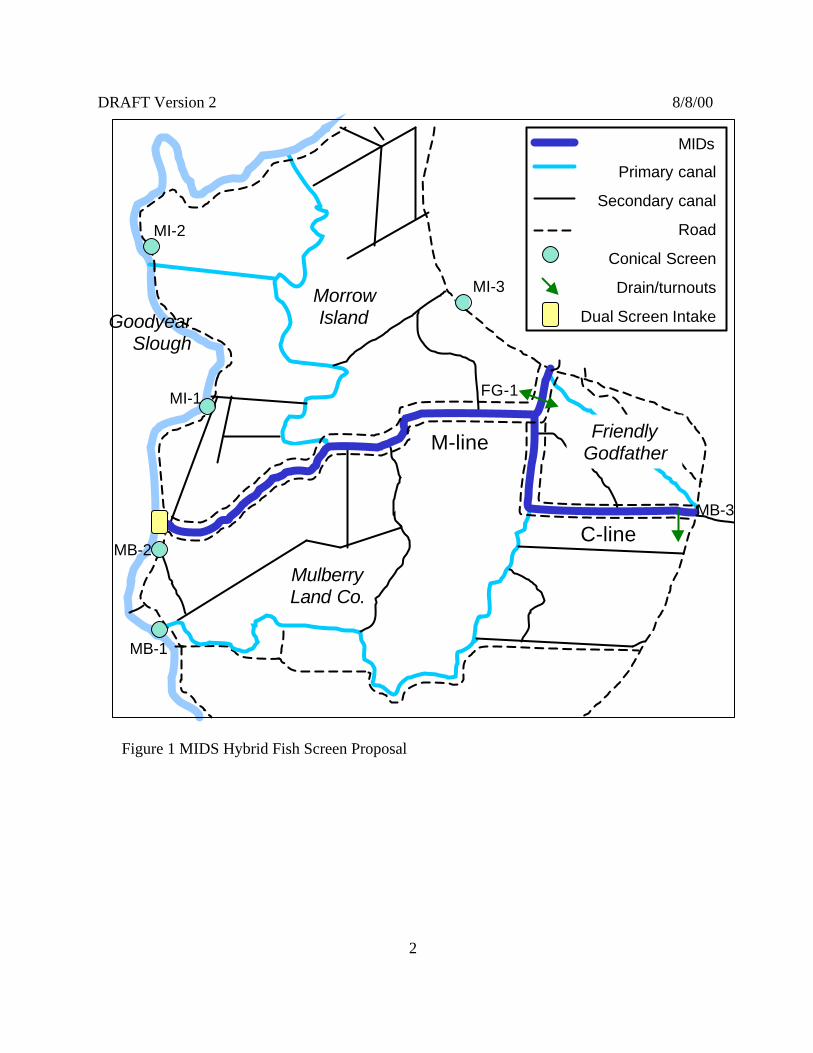
The Department of Water Resources and the U.S. Bureau of Reclamation proposeinstallation of seven conical fish screens on Morrow Island. On July 2, 1997 the U.S. ArmyCorps of Engineers issued a permit (No. 20698N) to perform maintenance on the Morrow IslandDistribution System (MIDS). Permit conditions required installation of a fish screen on theGoodyear Slough diversion structure of the MIDS. Under consultation with the U.S. Fish andWildlife Service and U.S. Army Corps of Engineers, DWR and USBR have developed a “HybridProposal” for meeting the permit condition (Figure 1). The Hybrid Proposal consists of thefollowing:
♦ Installation of 2 12-foot conical screens and 1-48 inch drain at the MIDS intake facility;♦ Installation of 5 12-foot conical screens distributed along Goodyear and Suisun Sloughs;♦ Addition of 1-36 inch turnout along C-line;♦ Addition of 1-36 inch combination turnout and drain along M-line; and♦ New Operations Agreement for the MIDS.
Actions to be conducted on the MIDS will be completed by DWR. These include all of theactivities except the five distributed conical screens on Goodyear and Suisun Slough. The fiveconical screens will be placed on individual ownerships serviced by MIDS. Installation of thesescreens will be conducted by the Suisun Resource Conservation District (SRCD) under contractwith the Department.
M-line
C-line
GoodyearSlough
MorrowIsland
MulberryLand Co.
FriendlyGodfather
MIDs
Primary canal
Secondary canal
Road
Conical Screen
Drain/turnouts
Dual Screen Intake
MI-3
MI-2
MI-1
MB-3
MB-1
MB-2
FG-1
Figure 1 MIDS Hybrid Fish Screen Proposal
2
DRAFT Version 2 8/8/00

DRAFT Version 3 09/13/00
3
1.1 Project Scoping
The objective of the Hybrid Proposal is to prevent the entrainment losses of fish at theMIDS diversion on Goodyear Slough, while operating the MIDS at sufficient capacity to allowlandowners to follow wetland management operation procedures recommended in the IndividualOwnership Management Plan. Several fish screen alternatives were evaluated with respect to thefollowing criteria: acceptability to landowner(s), environmental impact, permitting requirements,time requirement, managed wetlands operations/flexibility, water quality impacts,redeployment/salvage potential, reduction of system sedimentation, operations and maintenancerequirements, consistency with SMPA Amendment 3, procurement requirement, and cost. The“Hybrid Proposal” was determined to be the preferred alternative, meeting the screeningrequirements of the USACE Permit, while providing operational flexibility to the managedwetlands and resulting in a less significant environmental impact than other alternatives. Section5.0 Alternative Analysis contains a more detailed discussion of the project alternatives.
1.2 Scope of Environmental Impacts Analysis
This assessment evaluates the status of plant and animal species which are known or aresuspected of potentially occurring in the mitigation areas. The specific objectives of this reportare to provide accurate, up-to-date information on the ecology and occurrence of the pertinentspecies with special reference to the project area of the Morrow Island Distribution System in thesouthwestern Suisun Marsh, and to make assessments of the potential for impacts of the proposedproject.
2.0 PROJECT AREA
Suisun Marsh is in southern Solano County, California, west of the Sacramento-SanJoaquin Delta and north of Suisun Bay (Figure 2). This tidally influenced marsh is a vitalwintering and nesting area for waterfowl of the Pacific Flyway, and it represents approximately12 percent ofCalifornia's remainingwetland habitat. Themajority of the 52,000acres of managedwetlands is privatelyowned and managed aswaterfowl clubs by 153different landowners.
Fairfield
Suisun Marsh
Figure 2. Location of Suisun Marsh
DRAFT Version 3 09/13/00
4
2.1 Morrow Island Distribution System
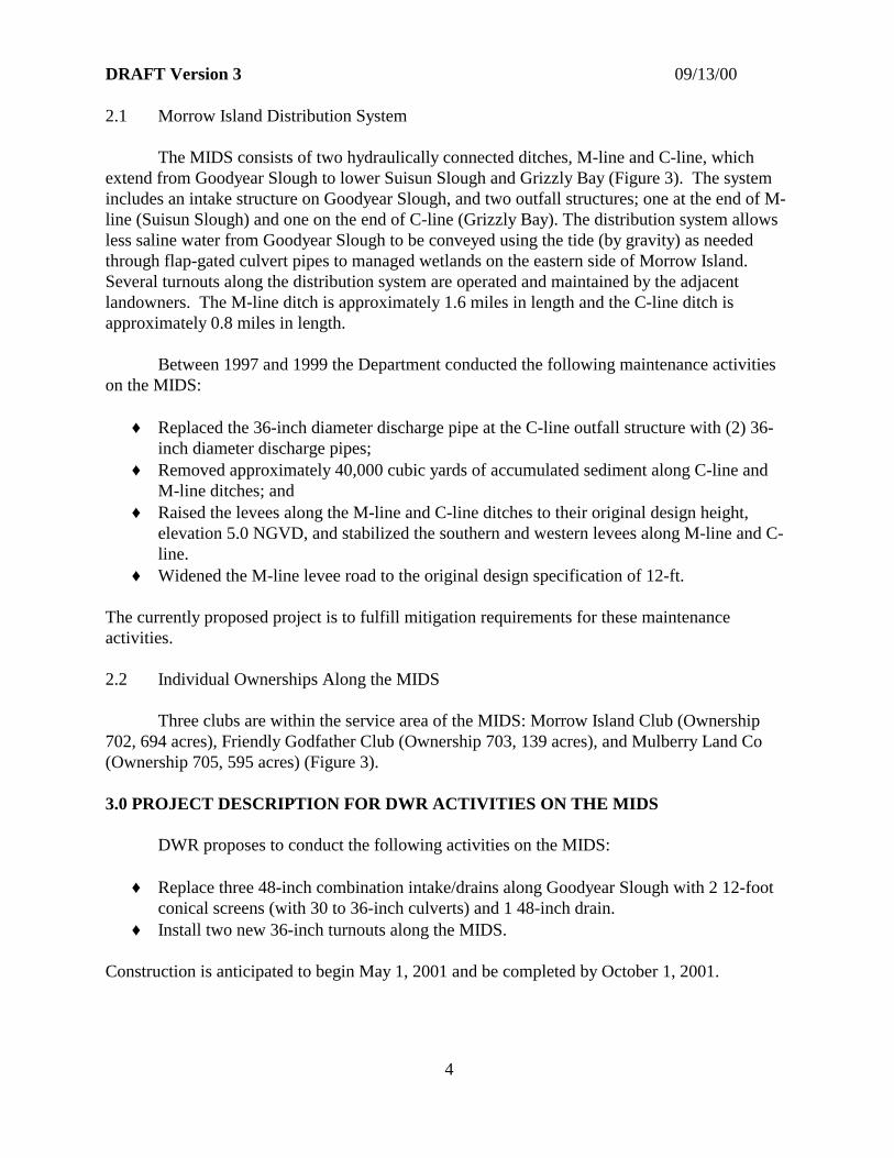
The MIDS consists of two hydraulically connected ditches, M-line and C-line, whichextend from Goodyear Slough to lower Suisun Slough and Grizzly Bay (Figure 3). The systemincludes an intake structure on Goodyear Slough, and two outfall structures; one at the end of M-line (Suisun Slough) and one on the end of C-line (Grizzly Bay). The distribution system allowsless saline water from Goodyear Slough to be conveyed using the tide (by gravity) as neededthrough flap-gated culvert pipes to managed wetlands on the eastern side of Morrow Island.Several turnouts along the distribution system are operated and maintained by the adjacentlandowners. The M-line ditch is approximately 1.6 miles in length and the C-line ditch isapproximately 0.8 miles in length.
Between 1997 and 1999 the Department conducted the following maintenance activitieson the MIDS:
♦ Replaced the 36-inch diameter discharge pipe at the C-line outfall structure with (2) 36-inch diameter discharge pipes;
♦ Removed approximately 40,000 cubic yards of accumulated sediment along C-line andM-line ditches; and
♦ Raised the levees along the M-line and C-line ditches to their original design height,elevation 5.0 NGVD, and stabilized the southern and western levees along M-line and C-line.
♦ Widened the M-line levee road to the original design specification of 12-ft.
The currently proposed project is to fulfill mitigation requirements for these maintenanceactivities.
2.2 Individual Ownerships Along the MIDS
Three clubs are within the service area of the MIDS: Morrow Island Club (Ownership702, 694 acres), Friendly Godfather Club (Ownership 703, 139 acres), and Mulberry Land Co(Ownership 705, 595 acres) (Figure 3).
3.0 PROJECT DESCRIPTION FOR DWR ACTIVITIES ON THE MIDS
DWR proposes to conduct the following activities on the MIDS:
♦ Replace three 48-inch combination intake/drains along Goodyear Slough with 2 12-footconical screens (with 30 to 36-inch culverts) and 1 48-inch drain.
♦ Install two new 36-inch turnouts along the MIDS.
Construction is anticipated to begin May 1, 2001 and be completed by October 1, 2001.

M-line
C-line
MID
S in
take
GoodyearSlough
MorrowIsland
MulberryLand Co.
FriendlyGodfather
MIDs
Primary canal
Secondary canal
Road
Diversions
Figure 3 Existing Morrow Island Distribution System
DRAFT Version 2 8/8/00
5

DRAFT Version 3 09/13/00
6
3.1 Fish Screens
DWR will install two 12-foot conical screens on the intake structure to MIDS(Figure 4). Currently, three 48-inch diameter culverts are used to divert water from GoodyearSlough into the distribution system (Figure 5). Each culvert functions as a floodgate and isequipped with manually operated slide type control valves. The culvert intakes are presentlyunscreened allowing fish to enter the MIDS through the diversion culverts. Diversions fromGoodyear Slough presently occur from October through May for flooding managed wetlands andpond water circulation.
3.1.1 Fish Screen Design Criteria
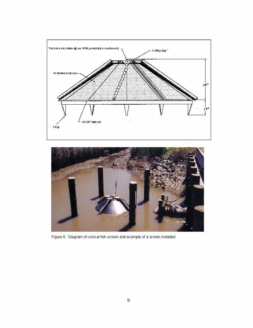
The fish screens will consist of 12-foot diameter conical screens. This screen design hasproven to be highly effective in Suisun Marsh. Thirteen conical screens are currently in usethroughout the Marsh. The fish screen unit will consist of two conical intake screens withantifouling screen materials connected to a steel bifurcation manifold (Figure 6). Through tidalaction, filtered water would flow through the screens, and through the 36-inch diameter culverts,into the distribution system. The screens meet the following design criteria:
♦ The screens are rated at 25 cfs each with a maximum approach velocity less than 0.2 fps. ♦ The screen material would be anti-fouling, corrosion resistant copper-nickel alloy with a
maximum slot opening of 3/32-inch for rectangular wedge wire or 5/32-inch forperforated or woven mesh materials.
♦ Screens prevent entrainment of all fish larger than 1-inch in length, including: juvenilesalmonids, striped bass, and delta smelt.
Each fish screen structure includes the following:
♦ One 12-foot diameter conical fish screen with submersible brush motor and controller.♦ One 12-foot diameter by 3.5 feet deep fiberglass intake/screen support tank.♦ One pressure-treated timber pile foundation, epoxy coated, with fabricated platform and
pile cap support.♦ One 30- to 36-inch diameter, six-foot long polyethylene intake pipe manifold with motor
operated slide gate and flap gate on the manifold outlet.♦ Approximately 30-foot long vinyl sheet pile barrier. Sheet pile barrier to have timber cap
and walkway to access intake facility and drain gate.♦ One 36-inch diameter slide gate, manually operated, mounted on land side of barrier with
flap gate on water side.♦ Electronic controls and monitoring equipment.♦ One 16’ x 16’ pressure-treated timber screen laydown pad.♦ Bumper/debris boom support piles, pressure treated timber.

Figu
re 4
. MID
S In
take
Fish
Scr
een
Stru
ctur
e
7

?
(Facing East)
(Facing North)
Intake
Goodyear Slough
Goodyear Slough
Intake
Morrow Island Distribution System
Morrow Island Distribution System
Not to Scale(depicted locations are approximate)
Figure 5 MIDS Existing Intake Facility
Approximate locationof fish screen
8
9

DRAFT Version 3 09/13/00
10
3.1.2 Installation of Fish Screens on MIDS Intake
The fish screens are anticipated to be installed at the MIDS intake between May 1, 2001and October 1, 2001. Installation efforts will generally follow the procedures listed below:
♦ Construction will begin with demolition and removal of the existing intake facility. Acoffer dam will be installed along the bank of Goodyear Slough and water levels withinthe MIDS will be lowered as much as possible prior to demolition and removaloperations. The existing culverts will likely be excavated and removed in stages from thelevee in which they are presently encased. Sections of sheet piling may be usedtemporarily within, or adjacent to, the excavations to maintain slopes and/or prevent orrestrict the movement of water.
♦ Two 30- to 36-inch diameter screen discharge culverts and one 48-inch drain culvert willbe installed in the levee after removal of the existing culverts. The new culverts may beinstalled within the excavations created from the removal of the existing culverts, or, theymay be placed in separate excavations.
♦ The new culverts will likely be constructed of a polymer material such as high-densitypolyethylene (HDPE). The culverts will probably be fitted with flow control valves priorto placement in the excavations. The excavations in which the new culverts are placed,and any excavations remaining from the removal of the preexisting culverts, will bebackfilled and compacted so as to reestablish the structural and hydraulic integrity of thelevee.
♦ A headwall, approximately sixty feet in length, will be constructed along the western edgeof the gravel roadway that crosses the current intake structure. Wingwalls will beconstructed at both ends of the headwall for slope transition. Up to about 500-cubic yardsof bank material will be removed between the wall and Goodyear Slough to provide roomfor the installation of the fishscreens. Additional room is needed in the slough for boats topass the screen facility.
♦ The headwall will be constructed using sheetpiling. The wall will be reinforced usingsteel or treated wood pilings driven in along the waterside of the headwall. Headwallconstruction efforts may require the use of an impact or vibratory pile driver.
♦ Fish screen installation efforts will begin with the installation of six steel or treated woodpilings. The pilings are needed for supporting the fish screens in Goodyear Slough. Two12-foot diameter stainless-steel or copper-nickel fish screens will then be connected to thedischarge culverts and secured to the piling set.
♦ Revetment will be placed along the levee on the interior side of the intake structure toprevent erosion (Figures 4 and 7).

?
Revetment(to be installed)
Intake Facility
Morrow Island Distribution System
(Facing West)
(Facing Southwest)
Revetment(to be installed)
Not to Scale(depicted locations are approximate)
Figure 7 MIDS Revetment installation at intake facility
11

DRAFT Version 3 09/13/00
12
♦ Final construction efforts at the MIDS intake will likely consist of the installation ofwalkways, screen/valve controls, and electrical hookups; and construction of screenlaydown platforms. The laydown platforms will be located just off the western edge ofMorrow Island Road immediately north of the intake facility. Minor regrading of theupper surface of the MIDS levees may be required to restore road conditions and leveecrown elevations to their former specifications.
Material excavated during construction operations will be stockpiled on the crown of the MIDSlevee a short distance from the intake site. Any surplus material will be properly disposed of atan off-site location.
3.1.3 Fish Screen Laydown Platform Installation
A laydown platform will be installed for each fish screen to allow the screens to beremoved from the slough for annual maintenance. The platforms for the intake screens will belocated approximately 20 feet north of the proposed intake structure along the levee road. Eachplatform will be approximately 16-feet square and elevated about 2 feet off the ground. Fourwood pilings or pre-cast concrete piers will be used at each platform site. The platforms will beconstructed on site and placed on the pilings.
3.1.4 Disposal of Dredged Material
In order to allow adequate flow from Goodyear Slough to reach the fish screens, arelatively small amount of material may be dredged at the intake location. It is anticipated that nomore than about 300 cubic yards of material will be dredged. All excavated material will beproperly disposed of at a site away from the marsh.
3.2 Installation of New Turnouts/Drains Along the System
Two new turnouts will be installed along the MIDS (Figure 1). One 36-inch turnout willbe installed along the MIDS C-line on Mulberry Land Company (Site MB-3) (Figure 8). Thiswill allow Mulberry’s Pond C to be filled directly from the MIDS. A second 36-inchcombination turnout and drain will be placed on along M-line to serve the Friendly Godfatherproperty (Site FG-1) (Figure 9).
Both turnouts will be constructed using 36-inch HPDE culverts. The Mulberry (MB-1) culvertwill be fitted with a flap gate on the Mulberry end and a slide gate on the MIDS end. TheFriendly Godfather (FG-1) culvert will be fitted with combination liftgate/flapgate valves on bothends to allow the culvert to be used for either filling or draining.
Installation efforts will start when the water level in the MIDS is at a minimum andadjoining properties have been adequately drained. Trenches will be excavated through the leveeof the MIDS to allow placement of the new culverts. Material excavated from the levee will bestockpiled temporarily on the crown of the MIDS levee system a reasonable distance from theexcavations. The material will be placed back into the excavations and compacted after the

?
Morrow IslandDistribution System “C” Line Outfall New Turnout
(fill only)
Existing Turnout/Drain(to remain)
New 36” Turnout
Morrow Island Distribution System
Mulberry Land Company Pond C
( Facing South )
(depicted locations are approximate)
( Facing East )
Not to Scale
Figure 8 Turnout installation site
13

?
(depicted locations are approximate)
(Facing North)
Proposed Location of 36-inch Diameter Fill/Drain Pipe
(Facing South)
Friendly Godfather
Morrow Island Distribution System(M-Line)
(C-Line)
Friendly GodfatherMorrow Island Distribution System (M-Line)
Not to Scale
Figure 9 Site FG-1
14
DRAFT Version 3 09/13/00
15
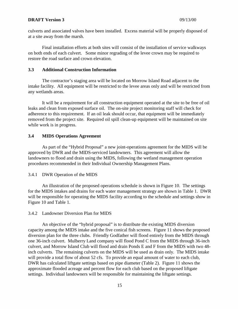
culverts and associated valves have been installed. Excess material will be properly disposed ofat a site away from the marsh.
Final installation efforts at both sites will consist of the installation of service walkwayson both ends of each culvert. Some minor regrading of the levee crown may be required torestore the road surface and crown elevation.
3.3 Additional Construction Information
The contractor’s staging area will be located on Morrow Island Road adjacent to theintake facility. All equipment will be restricted to the levee areas only and will be restricted fromany wetlands areas.
It will be a requirement for all construction equipment operated at the site to be free of oilleaks and clean from exposed surface oil. The on-site project monitoring staff will check foradherence to this requirement. If an oil leak should occur, that equipment will be immediatelyremoved from the project site. Required oil spill clean-up equipment will be maintained on sitewhile work is in progress.
3.4 MIDS Operations Agreement
As part of the “Hybrid Proposal” a new joint-operations agreement for the MIDS will beapproved by DWR and the MIDS-serviced landowners. This agreement will allow thelandowners to flood and drain using the MIDS, following the wetland management operationprocedures recommended in their Individual Ownership Management Plans.
3.4.1 DWR Operation of the MIDS
An illustration of the proposed operations schedule is shown in Figure 10. The settingsfor the MIDS intakes and drains for each water management strategy are shown in Table 1. DWRwill be responsible for operating the MIDS facility according to the schedule and settings show inFigure 10 and Table 1.
3.4.2 Landowner Diversion Plan for MIDS
An objective of the “hybrid proposal” is to distribute the existing MIDS diversioncapacity among the MIDS intake and the five conical fish screens. Figure 11 shows the proposeddiversion plan for the three clubs. Friendly Godfather will flood entirely from the MIDS throughone 36-inch culvert. Mulberry Land company will flood Pond C from the MIDS through 36-inchculvert, and Morrow Island Club will flood and drain Ponds E and F from the MIDS with two 48-inch culverts. The remaining culverts on the MIDS will be used as drain only. The MIDS intakewill provide a total flow of about 52 cfs. To provide an equal amount of water to each club,DWR has calculated liftgate settings based on pipe diameter (Table 2). Figure 11 shows theapproximate flooded acreage and percent flow for each club based on the proposed liftgatesettings. Individual landowners will be responsible for maintaining the liftgate settings.

DRAFT Version 3 09/13/00
16
Table 2 Approximate liftgate settings to maintain flow through fill pipes (all settings in inches)
48” Diameter Pipes 36” Diameter PipesHead Difference(Ditch to Pond)
Open each liftgate Head Difference(Ditch to Pond)
Open each liftgate
6 19 6 2212 16 12 1818 15 18 16
Greater than 24 14 Greater than 24 15
3.5 MIDS Operations and Maintenance
DWR will be responsible for operating and maintaining the MIDS. Operation schedulewill follow the guidelines contained in Section 3.4, or the most recent approved version thereof. Individual landowners will be responsible for operations and maintenance of diversions along theMIDS.
WATER MANAGEMENT
STRATEGY
Floodup
Circulation
Drain
Circulation (Permanent Ponds)
Table 1 MIDS Facility Gate Settings
MIDS OPERATION 2 INTAKE CONICALS GOODYEAR DRAIN M-LINE DRAIN C-LINE DRAIN
Full Fill / No Drain Open Full Closed Closed Closed
Open Partial
No Fill / Full Drain Closed Open Full Open Full Open Full
Full Fill / Partial Drain Open Full Open Partial Open Partial
Open Full
1. Maintain ditch water level between 4-5 feet NGVD with maximum circulation. Use monitoring to determine drain gate setting.
Full Fill / Full Drain Open Full Open Full Open Full
1
SEPT OCT NOV DEC JAN FEB MAR APR MAY JUN JUL AUG SEPT(16th-30th) (1st-15th)
Floodup
Circulation
Drain
Circulation(Permanent Ponds)
WATER MANAGEMENT
STRATEGY
1. During the month of June the screens will be removed for cleaning and maintenance.2. During the month of August the MIDS will be operated to flush out sediments from the MIDS.
Figure 10 Annual operation guidelines for the Morrow Island Distribution System
1 2

MIDS
Existing culverts
New culverts
Ponds flooded by MIDS
Areas flooded by distributedconicals
Percent flow
M-line
C-lineMID
S in
take
GoodyearSlough
MorrowIsland
MulberryLand Co.
FriendlyGodfather
Figure 11 Proposed diversion plan
DRAFT Version 2 8/8/00
17
Pond C151 ac. (38%)
DWR est. 140 ac.
Club 703110 ac. (28%)
Ponds E & F
135 ac. (34%)
Not to Scale(depicted locations are approximate)
( )
DRAFT Version 3 09/13/00
18
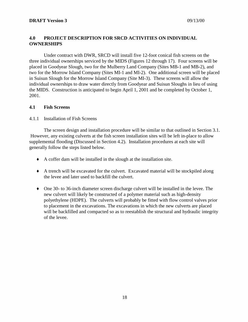
4.0 PROJECT DESCRIPTION FOR SRCD ACTIVITIES ON INDIVIDUALOWNERSHIPS
Under contract with DWR, SRCD will install five 12-foot conical fish screens on thethree individual ownerships serviced by the MIDS (Figures 12 through 17). Four screens will beplaced in Goodyear Slough, two for the Mulberry Land Company (Sites MB-1 and MB-2), andtwo for the Morrow Island Company (Sites MI-1 and MI-2). One additional screen will be placedin Suisun Slough for the Morrow Island Company (Site MI-3). These screens will allow theindividual ownerships to draw water directly from Goodyear and Suisun Sloughs in lieu of usingthe MIDS. Construction is anticipated to begin April 1, 2001 and be completed by October 1,2001.
4.1 Fish Screens
4.1.1 Installation of Fish Screens
The screen design and installation procedure will be similar to that outlined in Section 3.1. However, any existing culverts at the fish screen installation sites will be left in-place to allowsupplemental flooding (Discussed in Section 4.2). Installation procedures at each site willgenerally follow the steps listed below.
♦ A coffer dam will be installed in the slough at the installation site.
♦ A trench will be excavated for the culvert. Excavated material will be stockpiled alongthe levee and later used to backfill the culvert.
♦ One 30- to 36-inch diameter screen discharge culvert will be installed in the levee. Thenew culvert will likely be constructed of a polymer material such as high-densitypolyethylene (HDPE). The culverts will probably be fitted with flow control valves priorto placement in the excavations. The excavations in which the new culverts are placedwill be backfilled and compacted so as to reestablish the structural and hydraulic integrityof the levee.

?
(Facing Northeast)
Goodyear Slough
Proposed Location of
(depicted locations are approximate)
Goodyear Slough
(Facing Northeast)
Fish Screen
Not to Scale
Figure 12 Site MB-1, Goodyear Slough Side
19

?
Fish ScreenProposed Location of
(Facing South)
Goodyear Slough
(depicted locations are approximate)
Goodyear Slough
(Facing South)
Mulberry Land Company
Fish ScreenProposed Location of
Mulberry Land Company
Not to Scale
Figure 13 Site MB-2, Goodyear Slough Side
20

?
(Depicted location is approximate)
Morrow Island
Proposed Screen Location
(Facing Northeast)
Goodyear Slough
Not to Scale
Figure 14 Site MI-1, Goodyear Slough Side
21
?
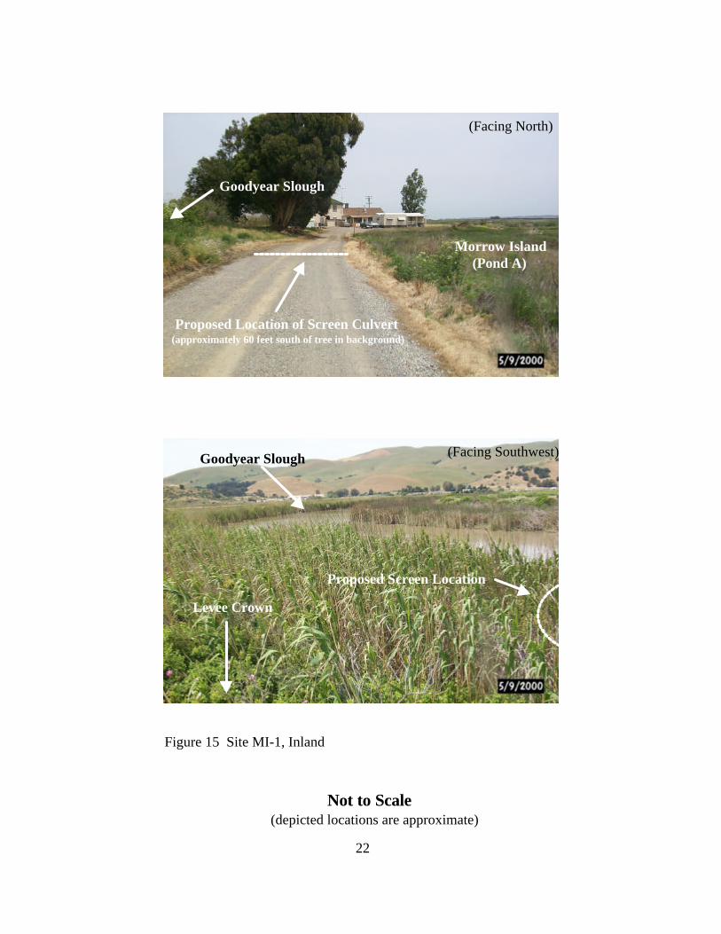
(Facing North)
Morrow Island (Pond A)
Proposed Location of Screen Culvert(approximately 60 feet south of tree in background)
(Facing Southwest)
Goodyear Slough
Goodyear Slough
Levee Crown
Proposed Screen Location
(depicted locations are approximate)Not to Scale
Figure 15 Site MI-1, Inland
22

?
Proposed Screen Location
(Facing Northeast)
Goodyear Slough
Morrow Island
Pierce Harbor (Facing Northwest)
Goodyear Sough
Proposed Screen Location (just offshore of levee)
Figure 16 Site MI-2Not to Scale
(depicted locations are approximate)
23

Proposed Screen Location
Suisun Slough
(Facing Southwest)
(Facing Northeast)
Proposed culvert alignment
Figure 17 Site MI-3Not to Scale
(depicted locations are approximate)
24

DRAFT Version 3 09/13/00
25
♦ A headwall, approximately 20 feet in length, will be constructed along the levee. Wingwalls will be constructed at both ends of the headwall for slope transition. Up toabout 100-cubic yards of bank material will be removed between the wall and slough toprovide room for the installation of the fishscreens.
♦ The headwall will be constructed using sheetpiling. The wall will be reinforced usingsteel or treated wood pilings driven in along the waterside of the headwall. Headwallconstruction efforts will likely include the use of an impact or vibratory pile driver.
♦ Fish screen installation efforts will begin with the installation of four steel or treated woodpilings. The pilings are needed for supporting the fish screens. The 12-foot diameterstainless steel or copper-nickel fish screen will then be connected to the discharge culvertsand secured to the piling set.
♦ Final construction efforts will likely consist of the installation of walkways, screen/valvecontrols, and electrical hookups; construction of screen storage platforms; and, anynecessary regarding of the levee and adjoining roadway to restore them to preexistingspecifications.
4.1.2 Fish Screen Platform Installation
Maintenance platforms will be installed for each site. The platform installation procedurewill follow that described in Section 3.1.
4.1.3 Fish Screen Operation
The individual owners will use the MIDS and the screened diversions as the first filloption. In the event that sufficient fill capacity is not obtained with the screened diversions,owners will use existing unscreened diversions to supplement. Unscreened diversions will not beused during periods of mandatory endangered species intake closures.
4.1.4 Fish Screen Maintenance
Individual owners will be responsible for operation activities on the fish screens placed ontheir property. DWR will provide for screen maintenance through a contract with SRCD, ordirectly through a private contractor.
4.2 Junction Box Installation
A flow control structure will be installed at the MI-3 site to allow the landowner to controlwater flow between ponds J and F (Figure 18). The structure will be installed in the existing toeditch on the interior side of the levee. The structure will consist of two berms on either side ofthe intake culvert. Each berm will have a 36-inch diameter culvert with a slide gate on theinterior (control structure) side.

Fish Screen Location
Flow Control Structure
Figure 18 Site MI-3 Flow Control Structure
culvert culvert
Culvert with slide gate
Toe ditch
Berm/Headwall(Not to scale)
26

DRAFT Version 3 09/13/00
27
5.0 ALTERNATIVE ANALYSIS
5.1 Development of Hybrid Proposal
The proposed project consists of a combination of fish screens on the MIDS and fishscreens on individual ownerships. The original USFWS Biological Opinion for the MIDSmaintenance included the following Terms and Conditions:
“…the Department of Water Resources shall install a screen on the GoodyearSlough diversion structure… The screen shall be either a 3/32-inch profile barscreen or a 5/32 inch perforated mesh plate…”.
In October 1999, DWR and USFWS met to discuss alternatives to building a large fishscreen structure on theMIDS intake. The goalwas to develop analternative that wouldprovide equivalentfisheries protection,but would avoidsignificant disturbanceto the environment aswell as allow theMIDS to operateeffectively. BetweenOctober 1999 and May2000, DWR workedcooperatively withDFG, USBR, SRCD,USFWS, and MorrowIsland landowners todevelop and evaluateseveral alternatives. Seven fish screenalternatives weredeveloped and arelisted below. Thealternatives wereevaluated with respectto twelve evaluationcriteria (Table 3).
Fish Screen Alternatives for the MIDS
1. Screens at the MIDS IntakeOption 1 – Inclined Plate ScreenOption 2 – Conical Screens
2. Smaller Screen Facilities with Pumping at the MIDS IntakeOption 1 – Use of Electric Pumps at the MIDS Intake with Inclined Plate ScreenOption 2 – Use of Electric Pumps at the MIDS Intake with Conical Screens
3. Operation of the MIDS as Open Ditch SystemOption 1 – Allow free movement of water through culvertsOption 2 – Open up the ends of the MIDS
Upgrade interior levee system to exterior levee specificationProvide distributed screens
4. Ground-Water Development
5. Land Purchase from Willing Sellers
6. Operation of the MIDS as a Drain-Only System Option 1 – Mobile Screens and PumpsOption 2 – Distributed Conical Screens
7. “Hybrid Proposal”2 Conical screens and 1 drain at MIDS Intake2 Additional turnouts – Clubs 703 and 7055 Distributed Conical Screens – Clubs 702 and 705

ALTERNATIVE
EVALUATION
CRITERIA
INCLINED
PLATE
SCREEN
CONICAL
SCREENS
INCLINED
PLATE
SCREEN
CONICAL
SCREEN
OPEN
CULVERTSOPEN ENDS
MOBILE
SCREENS AND
PUMPS
DISTRIBUTED
CONICAL
SCREENS
ACCEPTABILITY TO LAND
OWNER(S)
WATER QUALITY
ENVIRONMENTAL
IMPACT
PERMITTING
REQUIREMENTS
TIME REQUIRED TO
IMPLEMENT
MANAGED WETLAND
OPERATIONAL
FLEXIBILITY
REDEPLOYMENT/
SALVAGE POTENTIAL
REDUCTION OF SYSTEM
SEDIMENTATION
OPERATIONS AND
MAINTENANCE
CONSISTENCY WITH
AMENDMENT III
PROCUREMENT
REQUIREMENTS
APPROXIMATE COST
(MILLIONS) $2.2 $2.6 $2.1 $2.3 $4.6 $5.5 $2.1 $2.5
DWR, Suisun Marsh Branch 06/05/00 rev. 1
KEY
FOOTNOTES:
Table 3 Comparison of "Fish Friendly" alternatives for the Morrow Island Distribution System
GROUND WATER
DEVELOPMENT LAND PURCHASE
OPERATION OF THE MIDS AS
AN OPEN SYSTEM (WITH
DISTRIBUTED SCREENS)
SCREENS AT THE MIDS
INTAKE
SMALLER SCREEN FACILITY
AT THE MIDS INTAKE USING
PUMPS
OPERATION OF THE MIDS AS A
DRAIN-ONLY SYSTEMCONICAL SCREENS AT THE
MIDS INTAKE AND
DISTRIBUTED SCREENS
"HYBRID PROPOSAL"
3. Not feasible at this time. No commercially-available portable fish screens with a proven performance record were identified.
THIS RATING IS ASSIGNED
WHEN SMALL
PROBLEMS/DIFFICULTIES ARE
EXPECTED TO EXIST WITH AN
ALTERNATIVE IN RELATION TO
THE GIVEN EVALUATION
CRITERIA.
1. Not feasible because ground-water development potential is unknown at this time. Preliminary evaluation efforts indicate that ground-water production is not a viable alternative.2. Not feasible at this time. No willing sellers of land have been identified.
THIS RATING IS ASSIGNED WHEN VERY
SIGNIFICANT OR POSSIBLY INSURMOUNTABLE
PROBLEMS OR DIFFICULTIES ARE EXPECTED TO
EXIST WITH AN ALTERNATIVE IN RELATION TO
THE GIVEN EVALUATION CRITERIA.
THIS RATING IS ASSIGNED WHEN
RELATIVELY
MINOR PROBLEMS/DIFFICULTIES OR
NO
PROBLEMS/DIFFICULTIES ARE
EXPECTED TO EXIST WITH AN
ALTERNATIVE IN RELATION TO
THE GIVEN EVALUATION CRITERIA.
1 2
3
THIS RATING IS ASSIGNED WHEN
MODERATE PROBLEMS/DIFFICULTIES
ARE EXPECTED TO EXIST WITH AN
ALTERNATIVE IN RELATION TO THE
GIVEN EVALUATION CRITERIA.
THIS RATING IS ASSIGNED WHEN
SIGNIFICANT PROBLEMS OR
DIFFICULTIES ARE EXPECTED TO EXIST
WITH AN ALTERNATIVE IN RELATION
TO THE GIVEN EVALUATION CRITERIA.

DRAFT Version 3 09/13/00
29
Three of the suggested alternatives – ground water development, land purchase, and operation ofthe MIDS as a drain-only system – were determined not feasible at this time. Three otheralternatives – screens at the MIDS intake, small screen facility at the MIDS intake using pumps,and operation of the MIDS as an open system with distributed screens – were found to have verysignificant or possibly insurmountable problems. The “Hybrid Proposal” was determined to havethe least problems and/or difficulties with respect to the evaluation criteria and is considered thepreferred alternative. The preferred alternative consists of the installation of seven conical fishscreens, two turnouts on the MIDS, and a revised operations agreement for the MIDS.
A primary objective of the “hybrid proposal” is to distribute the existing MIDS diversioncapacity among the MIDS intake and the five conical fish screens. Distribution of the existingdiversion capacity between the MIDS intake and five fish screens will reduce the volume of waterdiverted at the MIDS intake. Figure 11 shows the proposed diversion strategy for the three clubsserviced by the MIDS. Reduction in the diversion volume at the MIDS intake will likely reducefish entrainment at the MIDS intake screens.
5.2 Site Selection
Site locations were selected to meet the following criteria: (1) provide optimum fill/draincapacity for landowners; and (2) result in minimal environmental impact. If possible, sites wereselected at existing (MB-1 and MB-2) or historical (MI-2 and MI-2) culvert locations, wherevegetation disturbance would be minimal. Two potential locations were originally identified forsite MI-3 (Figure 19). Location A is located at the site of an existing water quality monitoringstation. This location was identified because of its proximity to the monitoring station and theassociated human disturbance already occurring in this area. The screen would be located on theedge of the tidal fringe with a culvert running under the levee back to the toe ditch. Location B islocated about 400 feet south of the monitoring station, at a relatively narrow band of tidal fringe. This location was identified during aerial surveys as a potential site because of the narrow band oftidal fringe along that levee section. The two locations were ranked relative to each other basedon the criteria in Table 4. A rank of 1 indicates that the location is preferred with respect to thegiven criterion. As can be seen in Table 4, Location B is the preferred site for five of the sixcriteria, and was therefore chosen as the MI-3 site. Although there is not current humandisturbance at the selected site, it is anticipated that disturbance due to operations andmaintenance of the site will be minimal.
Table 4 Selection criteria and ranking for two MI-3 site locationsCriteria Location A Location BCurrent level of human disturbance 1 2Area of wetland vegetation disturbed 2 1Amount of dredging required 2 1Construction 2 1Operations and maintenance 2 1Permitting requirements 2 1


DRAFT Version 3 09/13/00
31
6.0 IMPACTS ANALYSIS
6.1 Loss of Wetlands
The installation of the seven fish screens will have less than significant impacts on both wetlandsand sensitive species. For wetlands, there will be a permanent loss of less than a 0.10 acres, andan additional area of less than 0.10 acres of temporarily disturbed wetlands. The wetland acreageestimated to be lost and disturbed is shown in Table 5.
Table 5 Estimated wetland vegetation impactsSite Wetland Vegetation ImpactsMI-1 400 sq ft permanent loss, 400 sq ft temporary disturbanceMI-2 no net loss of wetland, nominal amount disturbedMI-3 400 sq ft permanent loss, 400 sq ft temporary disturbanceMB-1 400 sq ft permanent loss, 400 sq ft temporary disturbanceMB-2 nominal amount lost, nominal amount temporary disturbanceMB-3 nominal amount lost or disturbedFG-1 nominal amount lost or disturbedMIDS Intake 1500 sq ft permanently lost, 1000 sq ft temporarily disturbed
For MI-1 and MI-2, the loss of wetland habitat will result from the construction of inlets for theinstallation of the screens. The construction of MI-2 will result in little wetland lost as theinstallation of the screen will be in an upland peninsula, which was created when an early culvertwas installed. The installation of MI-3 will result in no net loss of wetland, as the screen will beinstalled in Suisun Slough channel, connected by a pipe buried in an inlet that currently exists atthe site.
MB-1 and MB-2 will be installed at locations where culverts already exist. The loss of wetlandhabitat at those sites will be minimal and less than significant.
MB-3 and FG-1 will be place in interior levees. A minimal amount of wetland habitat will betemporarily disturbed.
The installation of the MIDS Intake screens will result in the largest disturbance, but within anarea of substantial human disturbance, and the minimal amount of additional wetland habitat lostwill be less than significant.
6.2 Sensitive Species Impacts
6.2.1 California Clapper Rail
The Clapper Rail is the species of primary concern relative to project activities. It may bepotentially impacted in two ways: through the loss of nesting/foraging habitat, and through

DRAFT Version 3 09/13/00
32
mechanical and human disturbance of nesting birds.
Clapper rails are not known along Goodyear Slough, so the potential to impact the species duringthe installation of screens MI-1 and MI-2, MB-1 and MB-2, and the MIDS Intake will beminimal. Pre-construction surveys (passive; active if no response) will be conducted in Spring2001, and no construction will allowed within 400 meters of an identified territory within theclapper rail nesting window. The loss of emergent wetland will be minimal, and in areas where itoccurs in narrow strips and close to substantial human disturbances, so the likelihood that nestsites would be lost due to the installation of the screens is nominal.
Clapper rails have been observed in Suisun Slough emergent wetland, and in close proximity tothe MI-3 screen site. Pre-construction surveys (passive; active if no response) will be conductedin Spring 2001, and no construction will allowed within 400 meters of an identified territorywithin the clapper rail nesting window. The project will be designed to minimize the potentialloss of a nest site and to avoid significantly fragmenting potential habitat by selecting thenarrowest section of emergent wetland. Because clapper rails have been observed near site MI-3,this site will be installed last to avoid the nesting season. The potential to significantly impactrails is extremely small at all sites.
6.2.2 Sensitive Plant Species
The sensitive plant species of most concern in the project area are Suisun Marsh aster (Asterlentus), delta tule pea (Lathyrus jepsonii var. jepsonii), and Mason’s lilaeopsis (Lilaeopsismasonii). A sensitive plant survey was conducted on August 1, 2000. Sensitive plant species orpotentially sensitive plant species were found at three sites. At site MI-1 and the MIDS intake(interior side), potential Suisun aster was found. The plant was classified as potential because itcould not be identified to species at this time. At site MI-3, delta tule pea was found along theproposed alignment. In spring 2001, prior to finalizing the culvert alignment for sites MI-1 andMI-3, a qualified botanist will conduct a sensitive plant survey. If possible, the alignments willbe moved to avoid disturbance of continuous patches of sensitive species. In the event thespecies cannot be avoided, the appropriate regulatory agencies will be consulted.
6.2.3 Critical Species Habitat
At site MI-1, a continuous pickleweed patch was found on the inside of Pond A along the culvertalignment. Pickleweed itself is not a sensitive plant species, but is critical habitat for theendangered salt marsh harvest mouse (Reithrodontomys raviventris). The proposed activitieswould permanently impact approximately 16 square feet along the inside edge of Pond A. Themajority of this impact will be outside of the pickleweed patch. During construction activities,some pickleweed may be temporarily impacted; however, these impacts will be kept to theminimum.

DRAFT Version 3 09/13/00
33
7.0 PERMIT REQUIREMENTS
7.1 Permits for DWR Activities on the MIDS
The Department will obtain the following environmental permits for this project:
♦ California Environmental Quality Act Notice of Exemption♦ California Department of Fish and Game Streambed Alteration Agreement♦ USACE Nationwide Permit♦ Regional Water Quality Control Board Water Quality Certification♦ San Francisco Bay Conservation and Development Commission Maintenance Permit
7.2 Permits for SRCD Activities on Individual Ownerships
Activities conducted by SRCD on the Individual Ownerships will be conducted undertheir USACE Regional General Permit Number 3 for Activities in the Suisun Marsh (No.24215N). The RGP contains provisions for installation of new water control structures andinstallation of fish screens on exterior water control structures. All terms and conditions of theRGP will be followed.