environmental degradation of thermal- barrier coatings by ... · environmental degradation of...
TRANSCRIPT

932 MRS BULLETIN • VOLUME 37 • OCTOBER 2012 • www.mrs.org/bulletin © 2012 Materials Research Society
Introduction The degradation of thermal-barrier coatings (TBCs) by molten
deposits resulting from a combination of impurities introduced
with the intake air and/or the fuel has been a concern since
the introduction of these material systems in gas turbines.
Corrosion by molten salts, especially alkaline sulfate-vanadate
mixtures, was of early interest owing to (1) their potential for
de-stabilization of the non-transformable, metastable tetragonal
yttria-stabilized zirconia ( t’ -YSZ) 1–3 commonly used as a topcoat
material and (2) their possible infi ltration toward the thermally
grown oxide (TGO) because their melting point is below the
temperature of the TGO/TBC interface (see the Introductory
article in this issue for a more detailed description of TBC
structure). The latter could have two consequences, one
related to a chemical attack of the TGO/bond coat, 4 and the
other associated with freezing of the salt within the TBC on
cooling and the ensuing loss of strain tolerance. 5 Phenomeno-
logical models have been developed to assess the effects of
sulfate infi ltration on coating life, 6 and promising materials
solutions have been proposed. 7–9 However, currently adopted
solutions rely primarily on fuel quality control.
As noted elsewhere in this issue, coatings are now enabling
to the design of advanced gas turbines, whether based on
metallic or ceramic components, with current goals calling for
material surface temperatures ≥ 1500°C. 10 While low melting
temperature salts remain a problem in some TBC applications,
they do not constitute a fundamental barrier to increased per-
formance, because the projected elevation in gas temperature
would be above the dew point of most sulfate/vanadate salts.
In contrast, the severe threat of silicate deposits at higher tem-
perature operation was recognized quite early. 11–13 The problem
arises from the ingestion of siliceous debris (airborne dust, sand,
ash) that adheres to the surfaces in the hot gas path (combustors,
airfoils, shrouds) and at peak temperatures of the engine cycle
(e.g., take-off or landing) yields glassy melts based on calcium-
magnesium alumino-silicates (CMAS). The glass wets all
coating materials of interest and can (1) penetrate the TBC
void spaces that accommodate the strain incompatibility with
the metallic substrate and/or (2) chemically dissolve the coat-
ing material, usually followed by precipitation of a modifi ed
oxide. 12–16 Because all prospective TBCs have to be porous/
segmented to render them strain-tolerant and most silicate
deposits melt around 1200°C, 12,13,17,18 any increases in operating
temperature needed to enhance turbine effi ciency would require
fi nding solutions to the CMAS problem. These deposits and
the associated degradation of TBCs are therefore the primary
focus of this article.
This article is organized into three main sections. The fi rst
section discusses the thermomechanical problem and the asso-
ciated driving forces. The second addresses thermochemical
Environmental degradation of thermal-barrier coatings by molten deposits Carlos G. Levi , John W. Hutchinson , Marie-Hélène Vidal-Sétif , and Curtis A. Johnson
Molten deposits based on calcium-magnesium alumino-silicates (CMAS), originating from siliceous debris ingested with the intake air, represent a fundamental threat to progress in gas turbine technology by limiting the operating surface temperature of coated components. The thermomechanical and thermochemical aspects of the CMAS interactions with thermal-barrier coatings, as well as the current status of mitigating strategies, are discussed in this article. Key challenges and research needs for developing adequate solutions are highlighted.
Carlos G. Levi, Materials Department , University of California , Santa Barbara ; [email protected]
John W. Hutchinson, School of Engineering and Applied Sciences , Harvard University ; [email protected]
Marie-Hélène Vidal-Sétif, Department of Metallic Materials and Structures , Onera , French Aerospace Lab ; [email protected]
Curtis A. Johnson, GE Global Research Center for Thermal Spray Research , Stony Brook University ; [email protected]
DOI: 10.1557/mrs.2012.230

ENVIRONMENTAL DEGRADATION OF THERMAL-BARRIER COATINGS BY MOLTEN DEPOSITS
933MRS BULLETIN • VOLUME 37 • OCTOBER 2012 • www.mrs.org/bulletin
issues, which lead to opportunities for mitigation. The third
deals with the experimental evaluation of the mitigation
approaches. It fi nishes with a brief outlook on critical research
needs.
Thermomechanical aspects CMAS related damage mechanisms and field evidence The TBC failure mechanisms identifi ed to date are illustrated in
Figure 1 . While the role of CMAS is viewed primarily in terms
of stiffening of the top t’- YSZ coat leading to shallow or deep
delaminations, 13 , 20 , 21 recent work has shown that CMAS contact
with the TGO results in chemical interactions and subsequent
delamination along the TGO 22 or may promote creep cavitation
in the bond coat wherein the delamination crack path would
propagate within the metal, rather than the ceramic layers. 23
As turbine temperatures continue to increase, existing mecha-
nisms will be aggravated, and new forms of damage may arise.
Moreover, CMAS infi ltration leads not only to stiffening of the
coating, but also to degradation of the insulating properties of
the TBC, 24 , 25 which may aggravate other intrinsic but nominally
unrelated forms of degradation (e.g., rumpling 26 ). The challenge
of coating life prediction thus acquires new dimensions in the
presence of CMAS.
An example of CMAS damage on current airfoils is
depicted in Figure 2 (left side) corresponding to state-of-
the-art t’- YSZ TBCs in a commercial aircraft engine. While
the thermal history cannot be ascertained, it is known that the
engine operated short fl ights (i.e., frequent cycles with sub-
stantial hot periods) in dusty environments. 27 The distress is
quite evident, extending beyond TBC loss to affect the TGO
and bond coat, in some places exposing the base metal. (The
coating on the right side of Figure 2 is discussed later in
the text.)
Delamination damage due to CMAS has been studied
in both commercial and military aircraft engines and exhibits
common features in coatings produced by electron-beam physi-
cal vapor deposition (EBPVD) 20 as well as dense, vertically
cracked TBCs produced by atmospheric plasma spray (APS). 21
In areas where the coating was cracked but not yet lost, the level
Figure 1. Extended menu of failure mechanisms typical of current thermal-barrier coatings (TBCs). 19 Three general modes of CMAS damage (lower right), characteristic of higher temperature operation, have been identifi ed so far. One involves delamination cracks propagating through the TBC, another leads to chemical attack of the thermally grown oxide (TGO) with concomitant loss of adherence, and a third results from creep cavitation of the bond coat below a heavily penetrated TBC. FOD, foreign object damage; da/dN, crack growth per cycle; du/dN, inward displacement of TGO per cycle.
Figure 2. Comparison of typical distress experienced by conventional thermal-barrier coatings (TBCs) based on 7–8% yttria-stabilized zirconia with an advanced TBC based on Gd x Zr 1– x O 2– x /2 pyrochlore, where x ≈ 0.5. The airfoils were part of an engine test in actual aircraft operation. 26 Courtesy of M.J. Maloney, Pratt & Whitney.

ENVIRONMENTAL DEGRADATION OF THERMAL-BARRIER COATINGS BY MOLTEN DEPOSITS
934 MRS BULLETIN • VOLUME 37 • OCTOBER 2012 • www.mrs.org/bulletin
of CMAS penetration was about one-half of the total thickness,
but deeper penetrations have been found in other airfoils. The
driving forces behind these failures are now examined briefl y.
Understanding the driving force for thermo-mechanical failure Release of the elastic strain energy stored in the coating supplies
the underlying driving force for the delamination and spalling
of TBC coatings. 28 The major source of this elastic energy is the
thermal expansion mismatch between the coating and the metal
substrate that occurs upon cooling. To facilitate understanding
of the origin of this elastic energy, the following discussion will
focus fi rst on isothermal cooling of the TBC/substrate system
and then consider more representative scenarios involving
a thermal gradient through the system in the hot state and
transient cooling.
Stress in the coatings is relaxed by creep at high tempera-
tures, and, thus, a reasonable working assumption is that
the coating stresses are zero at the hottest operating state. Cool-
down is relatively rapid, such that in most instances, one may
assume that thermoelastic behavior applies with no further
creep relaxation. Clear insights into the coating stress and elas-
tic energy emerge from a model that views the substrate as
thick and at uniform temperature. 28 The substrate constrains
bending, which is taken to vanish in the model and imposes an
in-plane biaxial strain change, – α s Δ T sub , on the coating. Here,
α s is the thermal expansion coeffi cient of the substrate and,
during cooling, 0
sub sub subT T TΔ = − is the temperature drop of
the substrate from its temperature in the hot state, 0
subT . For
simplicity, the coeffi cients of thermal expansion will be taken
to be temperature-independent. In the hot state, a steady-state
temperature distribution exists with 0
surT at the coating surface
and 0
subT at its interface with the substrate. The temperature
drop of the coating surface relative to the substrate is denoted
by ( )0
sur / sub sur sur subT T T TΔ = − − Δ .
Consider a single layer uniform coating with Young’s
modulus, E c , Poisson’s ratio, ν c , coeffi cient of thermal expan-
sion, α c , and thickness, h c . At any stage during cool-down,
idealize the temperature distribution in the coating to be linear
according to
( ) ( )sub C sur / suby y / ,T T TΔ = Δ + Δh (1)
with y as the through-thickness coordinate measured from the
interface. At any stage during cool-down, the state of stress in
the layer is equibiaxial, in-plane, given by
( ) ( )( )sub sur / suby y / .1
ET Tσ = −Δα Δ + α Δ
− νhC
C C CC
(2)
This equation reveals that cooling of the coating relative
to the substrate generates tensile stress depending on the full
coeffi cient of thermal expansion of the coating, while cooling
of the substrate imposes stress on the coating depending on the
thermal expansion mismatch, Δ α c = α S – α c . The elastic energy
per area in the coating associated with these thermal stresses,
available for release of the coating from the substrate under
plane strain conditions, is
2C C C
C sub C sub C sur / sub
C
2
C sur / sub
1
2 1
1.
3
U T T T
T
να α α
ν
α
E h
(3)
The interaction term, ( )( )C sub C sur / subT TΔα Δ α Δ , is important,
and it arises because the compressive coating stress driven
by cooling of the substrate, Δ T sub , can be offset by the tensile
stress associated with cooling of the coating surface relative
to the substrate, Δ T sur/sub . For the calculations shown here,
α C = 11 × 10 –6 C –1 , α S = 13 × 10 –6 C –1 , and the coating’s Poisson’s
ratio is ν c = 0.2.
The elastic energy/unit area given by Equation 3 is plotted in
normalized form ( U/E c h c ) in Figure 3 . Two limiting scenarios
are insightful. The fi rst applies when the coating and substrate
have a uniform temperature both in the hot state and while
cooled (i.e., Δ T sub increases while Δ T sur/sub = 0). This is repre-
sentative of furnace cycle tests involving isothermal holds and
relatively slow-cooling. Given that U scales with h c and con-
sidering a typical in-plane modulus absent CMAS penetration,
E c = 30 GPa, a “thin” 200 μ m TBC illustrative of aero-engine
blades would build up an elastic energy of ∼ 11 J·m –2 on cool-
ing from 0
sub800 CT = ° , whereas a “thick” 1-mm coating that
might be found in power generation components would reach
∼ 58 J·m –2 under the same conditions. Whether failure would
occur depends, of course, on the coating toughness under the
pertinent crack propagation mode, which is not well charac-
terized for these systems.
Consider now the case where the TBC is stiffened by com-
plete penetration of CMAS, elevating the Young’s modulus to
at least that of typical glasses (i.e., E c = 90 GPa). (Higher values
are likely given that most of the coating is dense t’- YSZ, with
E YSZ ≈ 200 GPa.) The elastic energy accumulated in the same
thermal excursion for the representative “thin” and “thick”
coatings cited previously would then go up by a factor of 3, to
∼ 35 and ∼ 173 J·m –2 , respectively. This simple result gives the
clearest insight into the role CMAS plays in debilitating a TBC
by degrading its in-plane compliance. CMAS infi ltration also
alters other properties of the coating such as the coeffi cient of
thermal expansion and the thermal conductivity, 24 , 25 but from
the vantage point of delamination, the major effect is the boost
in the coating modulus. While CMAS seldom infi ltrates all the
way to the coating/substrate interface, as assumed in computing
Figure 3 with a single value of E c , its effect on the elastic energy
in the coating is self-evident. In particular, a coating with an
ample reserve against delamination may experience a factor-
of-two increase in elastic energy/area due to thermal stresses
when partially infi ltrated by CMAS. 21 , 28
The second scenario of interest in Figure 3 is one wherein
the substrate temperature remains relatively unaffected, Δ T sub ≈ 0,
but the coating surface temperature drops rapidly relative to
the substrate, Δ T sur/sub > 0. This may occur, for example, if cool

ENVIRONMENTAL DEGRADATION OF THERMAL-BARRIER COATINGS BY MOLTEN DEPOSITS
935MRS BULLETIN • VOLUME 37 • OCTOBER 2012 • www.mrs.org/bulletin
gas suddenly impinges on the coating owing to an unexpected
fl ameout of an engine. As seen in Equation 2 , the thermal stress
in the coating is now proportional to α c Δ T sur/sub , and it devel-
ops primarily from self-constraint of the coating to thermal
contraction as its surface cools faster than the region closer to
the substrate. The trend in elastic energy/area that arises from
this contribution corresponds to the trace of the U/E c h c surface
in Figure 3 with the plane Δ T sub ≈ 0. If a rapid cooling event
occurs with Δ T sur/sub as large as 400°C, the elastic energy in the
coating in the early stage of cool-down could exceed that at the
fi nal cool-down (cf. the “quench” scenario in Figure 8 c). It is
also evident from Figure 3 that the buildup of elastic energy
can be ameliorated when both Δ T sub and Δ T sur/sub defi ne a path
along the valley in the U/E c h c surface (cf. the “slow cool”
scenario in Figure 8c ).
Numerous thermal scenarios beyond those presented pre-
viously must be considered to assess the ability of a TBC to
resist delamination. 29 To set the foundation for the discussion of
thermal gradient tests (see the section on Assessing the mitiga-
tion strategy), a rapid cooling scenario will be illustrated for a
system having a superalloy substrate 3.5 mm thick coated by a
representative t’- YSZ layer with h c = 1 mm. The
initial steady-state temperatures of the coating
surface and the underside of the substrate are
0
sur1300 CT = ° (above the melting point of most
typical CMAS deposits) and 800°C, respec-
tively, with 0
sub830 CT = ° at the coating/substrate
interface. Starting at time t = 0, forced cooling
air at 35°C is switched on, impinging on the
coating surface, with nominally stagnant air at
35°C on the underside of the substrate. (This
would not be typical of engine operation but
is of interest in laboratory tests.) The transient
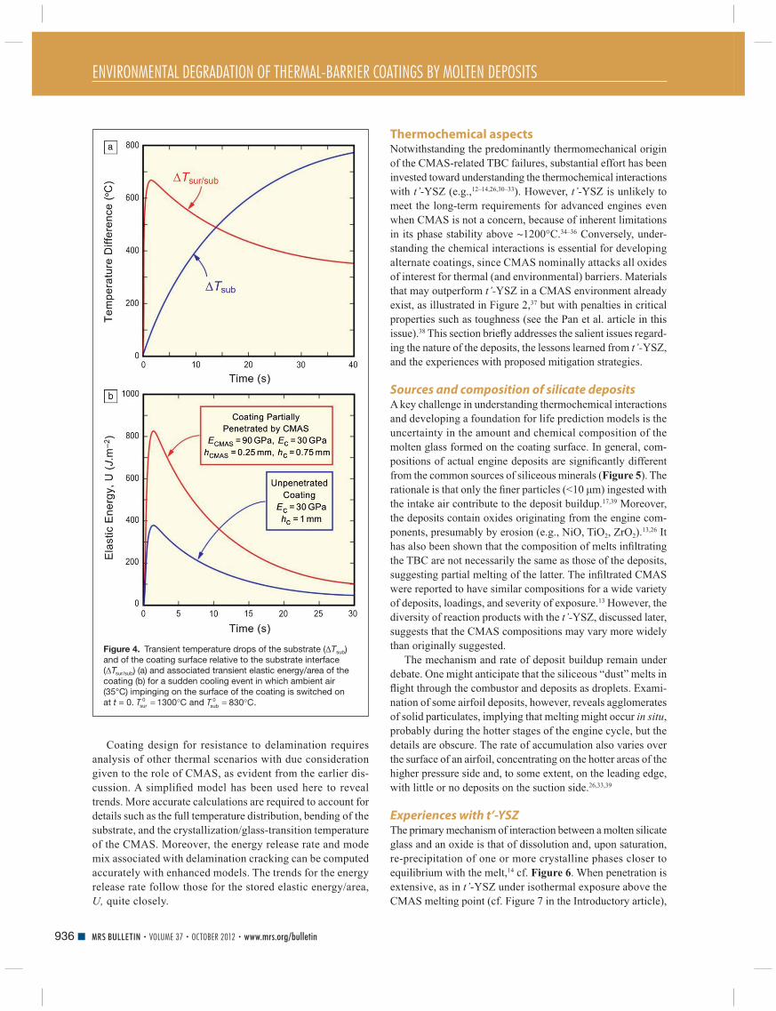
temperature history shown in Figure 4 a has
been computed using heat transfer coeffi cients
representative of forced air cooling at the coat-
ing surface and radiative cooling with natural
convection at the underside. 29 In this fi gure,
Δ T sub is identifi ed with the temperature drop
at the interface, and Δ T sur/sub is the temperature
drop of the coating surface relative to that at
the interface. Within the fi rst several seconds,
Δ T sur/sub peaks at ∼ 650°C, while Δ T sub remains
relatively small. As the cooling progresses, the
approach to the asymptotic limits in Figure 4a
refl ect cooling of the substrate to room tempera-
ture and the contribution of the initial temperature
gradient across the coating to Δ T sur/sub .
Transient histories of elastic energy/area in
the coating, U, based on the transient temperature
drops in Figure 4a , are plotted in Figure 4b for
a uniform coating 1 mm thick and for a 1 mm
coating having an upper layer of thickness
0.25 mm penetrated by CMAS. α c , α c , and ν c are
as specifi ed. The lower curve for the uniform
coating with no CMAS was computed using Equation 3 . The
upper curve was computed with an equation similar to 3, but
more complicated, for a bilayer coating. For simplicity, the
CMAS layer was assumed to have solidifi ed as soon as cooling
commenced, with the coating surface at 1300°C. In addition,
only E c was assumed to have been altered by CMAS; the
thermal properties are assumed to remain the same as those of
the unpenetrated coating.
The evolution of U in Figure 4b reveals that a TBC will
experience a peak in elastic energy in the early stage of a rapid
cool-down, within about 2 s for a 1 mm thick coating. More
importantly, CMAS penetration in the upper quarter of the
coating would double this peak energy. In the presence of an
initial thermal gradient, the 1 mm coating is most susceptible
to delamination under rapid cooling when the elastic energy
due to the thermal stress peaks. Under this scenario, the energy/
area in the cold state is much less than the early stage peak. This
is partly due to the fact that the tensile stress in the cold state,
due to the initial temperature gradient contribution to Δ T sur/sub ,
is offset by the compressive stress induced by the thermal
expansion mismatch with the substrate.
Figure 3. Normalized elastic energy/area in the coating ( U/E c h c ) calculated from Equation 3 and available for release under plane strain conditions due to thermal stress induced by cooling from an initially high temperature. Δ T sub and Δ T sur/sub are the temperature drops of the substrate and of the coating surface relative to the substrate, respectively, and the properties of the coating/substrate system are as defi ned in the text. Note that any value of U would scale with the coating modulus E c (e.g., due to stiffening by calcium-magnesium alumino-silicate penetration) and with the coating thickness, h c . Also note that cooling paths wherein Δ T sur/sub and Δ T sub change simultaneously may result in much lower strain energy buildup.
ENVIRONMENTAL DEGRADATION OF THERMAL-BARRIER COATINGS BY MOLTEN DEPOSITS
936 MRS BULLETIN • VOLUME 37 • OCTOBER 2012 • www.mrs.org/bulletin
Coating design for resistance to delamination requires
analysis of other thermal scenarios with due consideration
given to the role of CMAS, as evident from the earlier dis-
cussion. A simplifi ed model has been used here to reveal
trends. More accurate calculations are required to account for
details such as the full temperature distribution, bending of the
substrate, and the crystallization/glass-transition temperature
of the CMAS. Moreover, the energy release rate and mode
mix associated with delamination cracking can be computed
accurately with enhanced models. The trends for the energy
release rate follow those for the stored elastic energy/area,
U, quite closely.
Thermochemical aspects Notwithstanding the predominantly thermomechanical origin
of the CMAS-related TBC failures, substantial effort has been
invested toward understanding the thermochemical interactions
with t’- YSZ (e.g., 12 – 14 , 26 , 30 – 33 ). However, t’- YSZ is unlikely to
meet the long-term requirements for advanced engines even
when CMAS is not a concern, because of inherent limitations
in its phase stability above ∼ 1200°C. 34 – 36 Conversely, under-
standing the chemical interactions is essential for developing
alternate coatings, since CMAS nominally attacks all oxides
of interest for thermal (and environmental) barriers. Materials
that may outperform t’- YSZ in a CMAS environment already
exist, as illustrated in Figure 2 , 37 but with penalties in critical
properties such as toughness (see the Pan et al. article in this
issue). 38 This section briefl y addresses the salient issues regard-
ing the nature of the deposits, the lessons learned from t’- YSZ,
and the experiences with proposed mitigation strategies.
Sources and composition of silicate deposits A key challenge in understanding thermochemical interactions
and developing a foundation for life prediction models is the
uncertainty in the amount and chemical composition of the
molten glass formed on the coating surface. In general, com-
positions of actual engine deposits are signifi cantly different
from the common sources of siliceous minerals ( Figure 5 ). The
rationale is that only the fi ner particles (<10 μ m) ingested with
the intake air contribute to the deposit buildup. 17 , 39 Moreover,
the deposits contain oxides originating from the engine com-
ponents, presumably by erosion (e.g., NiO, TiO 2 , ZrO 2 ). 13 , 26 It
has also been shown that the composition of melts infi ltrating
the TBC are not necessarily the same as those of the deposits,
suggesting partial melting of the latter. The infi ltrated CMAS
were reported to have similar compositions for a wide variety
of deposits, loadings, and severity of exposure. 13 However, the
diversity of reaction products with the t’- YSZ, discussed later,
suggests that the CMAS compositions may vary more widely
than originally suggested.
The mechanism and rate of deposit buildup remain under
debate. One might anticipate that the siliceous “dust” melts in
fl ight through the combustor and deposits as droplets. Exami-
nation of some airfoil deposits, however, reveals agglomerates
of solid particulates, implying that melting might occur in situ ,
probably during the hotter stages of the engine cycle, but the
details are obscure. The rate of accumulation also varies over
the surface of an airfoil, concentrating on the hotter areas of the
higher pressure side and, to some extent, on the leading edge,
with little or no deposits on the suction side. 26 , 33 , 39
Experiences with t’-YSZ The primary mechanism of interaction between a molten silicate
glass and an oxide is that of dissolution and, upon saturation,
re-precipitation of one or more crystalline phases closer to
equilibrium with the melt, 14 cf. Figure 6 . When penetration is
extensive, as in t’- YSZ under isothermal exposure above the
CMAS melting point (cf. Figure 7 in the Introductory article),
Figure 4. Transient temperature drops of the substrate ( Δ T sub ) and of the coating surface relative to the substrate interface ( Δ T sur/sub ) (a) and associated transient elastic energy/area of the coating (b) for a sudden cooling event in which ambient air (35°C) impinging on the surface of the coating is switched on at t = 0. = °Tsur 1300 C0 and = °Tsub 830 C0 .

ENVIRONMENTAL DEGRADATION OF THERMAL-BARRIER COATINGS BY MOLTEN DEPOSITS
937MRS BULLETIN • VOLUME 37 • OCTOBER 2012 • www.mrs.org/bulletin
the extent of interaction can be signifi cantly different within the
pore spaces, where the melt volume is small relative to the TBC,
compared with the surface, where the relative proportion of melt
is much larger. Laboratory approaches aiming to replicate the
interaction in service range from those using materials sampled
from the fi eld, 12 , 13 , 31 to the use of “synthetic CMAS” similar in
composition to the deposit (see References 32 and 47 ), to studies
using simplifi ed compositions with only a few oxides. 14 , 44 , 49
In a baseline study, t’- YSZ (EBPVD) dissolved isothermally
in a model CMAS melt with (Ca+Mg):Si ≈ 0.93 (1300°C/4h)
and reprecipitated either Y-lean ZrO 2 , transformable to
monoclinic on cooling, or fully stabilized Y-rich cubic ZrO 2 ,
depending on the alumina content of the melt. 14
Similar observations were made on APS
t’- YSZ exposed to a more complex CMAS with
(Ca+Mg):Si ≈ 0.86 (1121°C/24h). 30 In contrast,
a simpler CAS melt with Ca:Si ≈ 0.41 and
similar Al (1200°C/4h) yielded Ca 2 ZrSi 4 O 12 . 49
A complex “synthetic volcanic ash” with an
even lower (Ca+Mg):Si ≈ 0.15 (1200°C/1h)
was reported to form ZrSiO 4 (zircon) at the
interface, whereas a lignite fl y ash with a
much higher (Ca+Mg):Si ≈ 1.1 produced pre-
dominantly tetragonal YSZ. 31 In most of these
experiments, the residual CMAS was largely
amorphous upon cooling, although crystalline
silicates were found in some cases. Observations
in fi eld specimens were at least qualitatively
consistent with these simulated exposures, with
no evidence that the reaction products played
a signifi cant role in mitigating penetration and
the ensuing stiffening. In one peculiar service
airfoil, where CaSO 4 was found to have infi l-
trated the TBC prior to CMAS exposure, there
was no detectable reaction within the spaces
in the columnar t’- YSZ structure, but CaZrO 3
was found on top of the column tips. 26 The
latter reacted with the overlying silicate melt,
presumably deposited later, to yield a complex garnet phase
(kimzeyite) with composition Ca 3 (Zr,Mg,Ti) 2 (Fe,Al,Si) 3 O 12 .
One might speculate that this reaction layer has potential for
CMAS mitigation, but at the expense of infi ltrating the TBC
with solid CaSO 4 , which would compromise the strain tolerance
of the coating. While the coating survived in this case, this does
not appear to be a practical solution in the long term.
Mitigation strategies Numerous CMAS mitigation strategies for YSZ have been pro-
posed in the literature, 46 , 50 , 51 but the persistence of the problem
suggests they have not been as effective as expected. Most cur-
rent approaches are based on manipulating the chemical reac-
tion between the TBC and the melt to accomplish two goals
simultaneously: (1) “immobilize” the melt by capturing its main
constituents into crystalline phases, most obviously silicates, and
(2) generating enough volume of precipitated products to fi ll the
pore spaces and block access of any residual melt to the remain-
ing TBC. The implications are that (1) the chemical reaction
should yield stable crystalline products in excess of the simple
reprecipitation of the Zr-rich phases, since those are essentially
replacing the dissolved material, and (2) the kinetics of both the
dissolution and reprecipitation processes must be competitive
with the infi ltration kinetics (i.e., the reaction must be quite fast).
Two broad strategies based on reactivity can be distin-
guished. One is based on alumina as the key reactant, which
combines with CaO and SiO 2 to form anorthite, CaAl 2 Si 2 O 8 . The
seemingly most successful approach in this category involves
the incorporation of alumina in metastable solid solution in
Figure 5. Concentration of predominant oxides in the composition of calcium-magnesium alumino-silicates, grouped by examples of sources of siliceous debris, compositions reported for actual deposits in engines, and model compositions used in laboratory investigations of the problem. (Small additions in some model compositions are not included.) Within each group, the compositions are listed from left to right in order of descending SiO 2 content, except for the average composition of the earth’s crust that serves as a reference. Reference citations are listed along the bottom of the image.
Figure 6. Schematic illustration of the dissolution-reprecipitation mechanism in yttria-stabilized zirconia, wherein the coating material dissolves in the molten glass and reprecipitates as one or more compositionally modifi ed crystalline phases. Some of the phases may form at high temperature, whereas others may precipitate upon cooling.
ENVIRONMENTAL DEGRADATION OF THERMAL-BARRIER COATINGS BY MOLTEN DEPOSITS
938 MRS BULLETIN • VOLUME 37 • OCTOBER 2012 • www.mrs.org/bulletin
YSZ, with a small amount of TiO 2 to catalyze the crystallization
process. 30 , 47 Because the volume of alumina required for effec-
tive mitigation is well beyond its equilibrium solubility in ZrO 2 ,
the approach exploits the ability of solution precursor plasma
spray 52 to generate the desired coatings (see the Sampath et al.
article in this issue for a description of this technique).
The second mitigation strategy is based on rare-earth (RE)
zirconates, exemplifi ed by Gd 2 Zr 2 O 7 (GZO). 31 , 53 , 54 This is the
material showing no signifi cant distress on the right-hand side
of Figure 2 . The merit of the approach relies on the dissolu-
tion of RE 2 Zr 2 O 7 to precipitate a Zr(RE,Ca)O x fl uorite phase
combined with a highly stable apatite silicate with nominal
composition Ca 2 RE 8 (SiO 4 ) 6 O 2 , where RE can be Y or one of
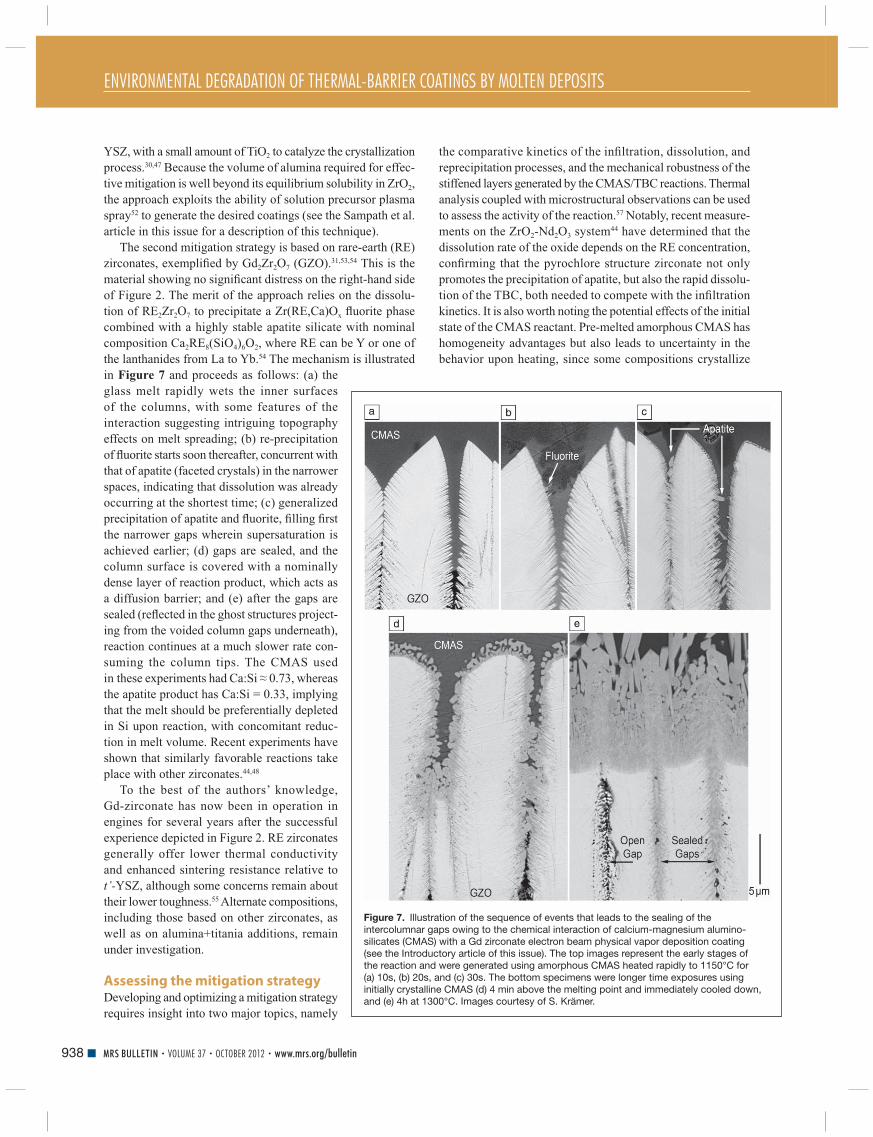
the lanthanides from La to Yb. 54 The mechanism is illustrated
in Figure 7 and proceeds as follows: (a) the
glass melt rapidly wets the inner surfaces
of the columns, with some features of the
interaction suggesting intriguing topography
effects on melt spreading; (b) re-precipitation
of fl uorite starts soon thereafter, concurrent with
that of apatite (faceted crystals) in the narrower
spaces, indicating that dissolution was already
occurring at the shortest time; (c) generalized
precipitation of apatite and fl uorite, fi lling fi rst
the narrower gaps wherein supersaturation is
achieved earlier; (d) gaps are sealed, and the
column surface is covered with a nominally
dense layer of reaction product, which acts as
a diffusion barrier; and (e) after the gaps are
sealed (refl ected in the ghost structures project-
ing from the voided column gaps underneath),
reaction continues at a much slower rate con-
suming the column tips. The CMAS used
in these experiments had Ca:Si ≈ 0.73, whereas
the apatite product has Ca:Si = 0.33, implying
that the melt should be preferentially depleted
in Si upon reaction, with concomitant reduc-
tion in melt volume. Recent experiments have
shown that similarly favorable reactions take
place with other zirconates. 44 , 48
To the best of the authors’ knowledge,
Gd-zirconate has now been in operation in
engines for several years after the successful
experience depicted in Figure 2 . RE zirconates
generally offer lower thermal conductivity
and enhanced sintering resistance relative to
t’- YSZ, although some concerns remain about
their lower toughness. 55 Alternate compositions,
including those based on other zirconates, as
well as on alumina+titania additions, remain
under investigation.
Assessing the mitigation strategy Developing and optimizing a mitigation strategy
requires insight into two major topics, namely
the comparative kinetics of the infi ltration, dissolution, and
reprecipitation processes, and the mechanical robustness of the
stiffened layers generated by the CMAS/TBC reactions. Thermal
analysis coupled with microstructural observations can be used
to assess the activity of the reaction. 57 Notably, recent measure-
ments on the ZrO 2 -Nd 2 O 3 system 44 have determined that the
dissolution rate of the oxide depends on the RE concentration,
confi rming that the pyrochlore structure zirconate not only
promotes the precipitation of apatite, but also the rapid dissolu-
tion of the TBC, both needed to compete with the infi ltration
kinetics. It is also worth noting the potential effects of the initial
state of the CMAS reactant. Pre-melted amorphous CMAS has
homogeneity advantages but also leads to uncertainty in the
behavior upon heating, since some compositions crystallize
Figure 7. Illustration of the sequence of events that leads to the sealing of the intercolumnar gaps owing to the chemical interaction of calcium-magnesium alumino-silicates (CMAS) with a Gd zirconate electron beam physical vapor deposition coating (see the Introductory article of this issue). The top images represent the early stages of the reaction and were generated using amorphous CMAS heated rapidly to 1150°C for (a) 10s, (b) 20s, and (c) 30s. The bottom specimens were longer time exposures using initially crystalline CMAS (d) 4 min above the melting point and immediately cooled down, and (e) 4h at 1300°C. Images courtesy of S. Krämer.

ENVIRONMENTAL DEGRADATION OF THERMAL-BARRIER COATINGS BY MOLTEN DEPOSITS
939MRS BULLETIN • VOLUME 37 • OCTOBER 2012 • www.mrs.org/bulletin
and then melt, whereas others soften gradually, complicating
the interpretation of the heat evolution history. 57
Thermomechanical assessment of CMAS infi ltrated/reacted
systems is still in its infancy. Thermal gradient tests are essential
since “isothermal” furnace cycle tests can lead to mislead-
ing results, and tests at 1300°C and above would compromise
superalloy substrates. Jet engine thermal shock (JETS) tests 50 , 56
are often used to assess the performance of TBCs under thermal
gradients and have been extended to CMAS testing (see the
Va β en et al. article in this issue). Burner rigs have also been
modifi ed to enable the injection of CMAS precursor solutions
through the fl ame 45 and are used successfully for testing plasma
spray ZrYAlTiO x coatings. 58 In both cases, the temperatures in
the front and back of the specimen are measured during the cycle
and used to calculate the evolution of the strain energy. 28
A thermal gradient test based on a laser heat source, schemat-
ically depicted in Figure 8 a, has been recently developed. 59
Proper specimen design allows monitoring of not only the
temperature at the surface and the backside of the substrate,
but also near the TGO/TBC interface. Thermal histories can
be accurately recorded and carefully manipulated using the
laser power-up and -down rates (e.g., Figure 8b ). In addition,
the system is set up with blue LED illumination and suitable
fi lters, 60 allowing visual monitoring of the coating surface during
heating and cooling. The thermal history can then be cast
in terms of Δ T sub and Δ T sur/sub (as discussed in the section on
Understanding the driving force for thermomechanical failure),
and used to calculate the strain energy buildup during cooling,
Figure 8c . Specimens are then examined after testing to identify
the type and extent of damage, Figure 8d–e , which can in turn
be correlated to the thermal history. It is anticipated that this
instrument will be invaluable in testing materials systems and
in helping refi ne the models needed to build life prediction
capabilities for TBCs with CMAS.
Outlook The CMAS problem in thermal-barrier coatings (TBCs) is
intrinsically thermomechanical, but thermochemical issues are
relevant to formulating an effective mitigation strategy. Because
the driving force for delamination scales with the square of
the temperature drop, the problem is expected to increase in
severity as TBCs are pushed to higher surface temperatures,
while the TBC/thermally grown oxide interface remains near
present levels. The grand challenge of the fi eld is the search for
a viable oxide that offers both CMAS resistance and adequate
toughness. For zirconia/hafnia based systems, the challenge
arises from the dichotomy in design approaches viz , CMAS
resistant compositions require large concentrations of reactive
dopants [Y, RE, Al], whereas tough compositions are based on
tetragonal crystal structures with much lower dopant content.
Developing the science base to guide the materials develop-
ment effort requires the effective integration of modeling and
Figure 8. Illustration of a (a) thermal gradient test based on a continuous CO 2 laser with backside cooling and extensive instrumentation used to probe the response of coatings infi ltrated with calcium-magnesium alumino-silicates to various thermal excursions. The thermal histories (e.g., (b)) can be varied over a substantial range, and ensuing thermal stresses and associated strain energies can be estimated based on models such as those described in the text; (c) projection of the surface in Figure 3 where the contours represent different levels of elastic energy and the paths are two representative thermal excursions corresponding to the samples whose micrographs are illustrated in (d) and (e). The insets show details of the cracks and in (e) the layer of reaction products on the surface of the GZO. Images courtesy of R.W. Jackson.

ENVIRONMENTAL DEGRADATION OF THERMAL-BARRIER COATINGS BY MOLTEN DEPOSITS
940 MRS BULLETIN • VOLUME 37 • OCTOBER 2012 • www.mrs.org/bulletin
experimental activities, ideally under an integrated computational
materials engineering (ICME) framework. 61 There is a paucity
of thermodynamic information on the relevant multicompo-
nent systems to help identify promising compositions that may
enable both improvements in toughness and effective reactivity
with CMAS melts, as well as to evaluate the sensitivity of candi-
date materials to the expected variability in melt compositions.
Improvements are also needed in the modeling outlined in this
article for predicting delamination driving forces, including,
for example, assessment of the extent of stress relaxation at the
highest temperatures and during cool-down and the interplay
of multilayer architectures. Studies on the relevant infi ltration,
dissolution, and crystallization kinetics for the appropriate com-
binations of silicate melts and thermal barrier oxides are also
essential. Once desirable compositions are identifi ed, it would
be necessary to develop the processing science to enable their
optimal synthesis into coatings.
On the experimental side, there is a long-standing need for
adequate methods for measuring and characterizing the
mechanical and thermal properties of coatings at high temper-
atures, including microstructures produced by thermochemical
interactions. It is worth noting that it has been a signifi cant chal-
lenge for the fi eld to devise methods to measure delamination
toughness, yet this is crucial in developing design approaches
to TBCs. Only within the past few years have experimental
methods emerged that are capable of measuring coating and
interface toughness with reasonable accuracy, but only at tem-
peratures close to ambient. The challenges are daunting, but so
are the needs for improving materials that would enable more
effi cient gas turbines for energy and propulsion.
Acknowledgments This article draws on lessons from research supported by
the Offi ce of Naval Research (CGL) and the French Defense
Research Organization (MHVS). The authors are indebted to
Dr. M.J. Maloney (PWA) for use of the illustration in Figure 2 ,
as well as to Drs. O. Lavigne (ONERA), D. Konitzer, and
D. Lipkin (GE) and Professors N.P. Padture (Brown) and M.R.
Begley (UCSB) for helpful discussions. The contributions of
Drs. R.W. Jackson and S. Krämer at UCSB are gratefully
acknowledged.
References 1. D.W. McKee , P.A. Siemers , Thin Solid Films 73 , 439 ( 1980 ). 2. A.S. Nagelberg , J. Electrochem. Soc. 132 ( 10 ), 2502 ( 1985 ). 3. R.L. Jones , C.E. Williams , Surf. Coat. Technol. 349 ( 1987 ). 4. C. Leyens , I.G. Wright , B.A. Pint , Oxid. Met. 54 ( 5/6 ), 401 ( 2000 ). 5. T.E. Strangman , Thin Solid Films 127 , 93 ( 1985 ). 6. T.E. Strangman , J. Neumann , A. Liu , “Thermal Barrier Coating Life—Prediction Model Development; Final Report” (NASA–Lewis Research Center , 1987 ). 7. R.L. Jones , “Experiences in Seeking Stabilizers for Zirconia having Hot Corrosion-Resistance and High Temperature Tetragonal (t’) Stability” (NRL/MR/6170–96–7841, Naval Research Laboratory , 1996 ). 8. S. Raghavan , M.J. Mayo , Surf. Coat. Technol. 160 , 187 ( 2002 ). 9. F.M. Pitek , C.G. Levi , Surf. Coat. Technol. 201 , 6044 ( 2007 ). 10. M.A. Alvin , F.S. Pettit , G.H. Meier , N.M. Yanar , M. Chyu , D. Mazzotta , W. Slaughter , V. Karaivanov , B. Kang , C. Feng , R. Chen , T.C. Fu , in 5th International Conference on Advances in Materials Technology for Fossil Power Plants , R. Viswanathan , D. Gandy , K. Coleman , Eds. ( Electric Power Research Institute, Inc. , Marco Island, FL , 2008 ), pp. 413 – 423 .
11. J.L. Smialek , F.A. Archer , R.G. Garlick , JOM 46 ( 12 ), 39 ( 1994 ). 12. F.H. Stott , D.J. de Wet , R. Taylor , MRS Bull. 19 ( 10 ), 46 ( 1994 ). 13. M.P. Borom , C.A. Johnson , L.A. Peluso , Surf. Coat. Technol. 86 – 87 , 116 ( 1996 ). 14. S. Krämer , J.Y. Yang , C.A. Johnson , C.G. Levi , J. Am. Ceram. Soc. 89 ( 10 ), 3167 ( 2006 ). 15. K.M. Grant , S. Krämer , J.P.A. Löfvader , C.G. Levi , Surf. Coat. Technol. 202 , 653 ( 2007 ). 16. K.M. Grant , S. Krämer , G.G.E. Seward , C.G. Levi , J. Am. Ceram. Soc. 93 ( 10 ), 3504 ( 2010 ). 17. J.L. Smialek , “The Chemistry of Saudi Arabian Sand: A Deposition Problem on Helicopter Turbine Airfoils” (NASA TM-105234, NASA Lewis Research Center , 1991 ). 18. W. Braue , J. Mater. Sci. 44 , 1664 ( 2009 ). 19. A.G. Evans , D.R. Clarke , C.G. Levi , J. Eur. Ceram. Soc. 28 ( 7 ), 1405 ( 2008 ). 20. C. Mercer , S. Faulhaber , A.G. Evans , R. Darolia , Acta Mater. 53 ( 4 ), 1029 ( 2005 ). 21. S. Krämer , S. Faulhaber , M. Chambers , D.R. Clarke , C.G. Levi , J.W. Hutchinson , A.G. Evans , Mater. Sci. Eng., A 490 , 26 ( 2008 ). 22. V.K. Tolpygo , private communication . 23. K.M. Wessels , R.W. Jackson , D.G. Konitzer , T.M. Pollock , C.G. Levi , presented at the International Conference on Metallurgical Coatings and Thin Films, San Diego, CA , 2012 . 24. L. Li , D.R. Clarke , Int. J. Appl. Ceram. Technol. 5 ( 3 ), 278 ( 2008 ). 25. J. Wu , H.B. Guo , Y.Z. Gao , S.K. Gong , J. Eur. Ceram. Soc. 31 , 1881 ( 2011 ). 26. W. Braue , P. Mechnich , J. Am. Ceram. Soc. 94 ( 12 ), 4483 ( 2011 ). 27. M.J. Maloney , in Turbine Forum ( Forum of Technology , Germany, Nice-Port St. Laurent, France , 2006 ). 28. A.G. Evans , J.W. Hutchinson , Surf. Coat. Technol. 201 , 7905 ( 2007 ). 29. S. Sundaram , D.M. Lipkin , C.A. Johnson , J.W. Hutchinson , J. Appl. Mech. ( 2012 ), in press . 30. A. Aygun , A.L. Vasiliev , N.P. Padture , X. Ma , Acta Mater. 55 ( 20 ), 6734 ( 2007 ). 31. A.D. Gledhill , K.M. Reddy , J.M. Drexler , K. Shinoda , S. Sampath , N.P. Padture , Mater. Sci. Eng., A 528 , 7214 ( 2011 ). 32. P. Mechnich , W. Braue , U. Schulz , J. Am. Ceram. Soc. 94 ( 3 ), 925 ( 2011 ). 33. M.-P. Bacos , J.-M. Dorvaux , O. Lavigne , R. Mévrel , M. Poulain , C. Rio , M.-H. Vidal-Setif , in Aerospace Lab: The ONERA Journal ( ONERA , Chatillon, France , 2011 ), issue 3 . 34. R.A. Miller , J.L. Smialek , R.G. Garlick , in Science and Technology of Zirconia , A.H. Heuer , L.W. Hobbs , Eds. ( The American Ceramic Society , Columbus, OH , 1981 ), vol. 3 , pp. 241 – 253 . 35. J.A. Krogstad , S. Krämer , D.M. Lipkin , C.A. Johnson , D.R.G. Mitchell , J.M. Cairney , C.G. Levi , J. Am. Ceram. Soc. 94 ( S1 ), S168 ( 2011 ). 36. D.M. Lipkin , J.A. Krogstad , Y. Gao , C.A. Johnson , W.A. Nelson , C.G. Levi , J. Am. Ceram. Soc. ( 2012 ), in press. 37. M.J. Maloney , US Patent 6,177,200 , 2001 . 38. R. Vassen , A. Stuke , D. Stöver , J. Therm. Spray Technol. 18 ( 2 ), 181 ( 2009 ). 39. T.E. Strangman , D. Raybould , A. Jameel , W. Baker , Surf. Coat. Technol. 202 , 658 ( 2007 ). 40. W.E. Ford , in Dana’s Textbook of Mineralogy with an Extended Treatise on Crystallography and Physical Mineralogy, 4th Edition ( Wiley , New York , 1954 ). 41. PTI , “Material Safety Data Sheet: Airport Runway Sand” ( 2007 ); www . powdertechnologyinc . com / secondary / msds . php . 42. H.E. Taylor , F.E. Lichte , Geophys. Res. Lett. 7 ( 11 ), 949 ( 1980 ). 43. W. Chesner , R. Collins , M. MacKay , J. Emery , “User Guidelines for Waste and Byproduct Materials in Pavement Construction” (Federal Highway Administration, Washington, DC, 1997) . 44. N. Chellah , M.-H. Vidal-Sétif , C. Petitjean , P.-J. Panteix , C. Rapin , M. Vilasi , in 8th International Symposium on High Temperature Corrosion and Protection of Materials (HTCPM8) ( Les Embiez , France , 2012 ). 45. T. Steinke , D. Sebold , D.E. Mack , R. Vaßen , D. Stöver , Surf. Coat. Technol. 205 , 2287 ( 2010 ). 46. A.K. Rai , R.S. Bhattacharya , D.E. Wolfe , T.J. Eden , Int. J. Appl. Ceram. Technol. 7 ( 5 ), 662 ( 2010 ). 47. J.M. Drexler , K. Shinoda , A.L. Ortiz , D. Li , A.L. Vasiliev , A.D. Gledhill , S. Sampath , N.P. Padture , Acta Mater. 58 6835 ( 2010 ). 48. J.M. Drexler , A.L. Ortiz , N.P. Padture , Acta Mater. 60 5437 ( 2012 ). 49. M.-P. Bacos , J.-M. Dorvaux , S. Landais , O. Lavigne , R. Mévrel , M. Poulain , C. Rio , M.-H. Vidal-Sétif , in Aerospace Lab: The ONERA Journal ( ONERA , Chatillon, France , 2011 ), issue 3 . 50. W.C. Hasz , C.A. Johnson , M.P. Borom , US Patent 5,660,885 ( 1997 ).

ENVIRONMENTAL DEGRADATION OF THERMAL-BARRIER COATINGS BY MOLTEN DEPOSITS
941MRS BULLETIN • VOLUME 37 • OCTOBER 2012 • www.mrs.org/bulletin
51. M. Fu , R. Darolia , M.D. Gorman , B.A. Nagaraj , US Patent 8,062,759 ( 2007 ). 52. N.P. Padture , K.W. Schlichting , T. Bhatia , A. Ozturk , B. Cetegen , E.H. Jordan , M. Gell , S. Jiang , T.D. Xiao , P.R. Strutt , E. Garcia , P. Miranzo , M.I. Osendi , Acta Mater. 49 , 2251 ( 2001 ). 53. S. Krämer , J.Y. Yang , C.G. Levi , J. Am. Ceram. Soc. 91 ( 2 ), 576 ( 2008 ). 54. J.M. Drexler , C.H. Chen , A.D. Gledhill , K. Shinoda , S. Sampath , N.P. Padture , Surf. Coat. Technol. 206 , 3911 ( 2012 ). 55. R.G. Wellman , J.R. Nicholls , Tribol. Int. 41 , 657 ( 2008 ). 56. R.V. Hillery , B.H. Pilsner , R.L. McKnight , T.S. Cook , M.S. Hartle , “Thermal Barrier Coating Life Prediction Model Development” (NASA CR 180807, General Electric, 1988) .
57. E. Zaleski , R.W. Jackson , C. Ensslen , C.G. Levi , 8th International Symposium on High Temperature Corrosion and Protection of Materials (HTCPM8) ( Les Embiez , France , 2012 ). 58. J.M. Drexler , A. Aygun , D. Li , R. Vaßen , T. Steinke , N.P. Padture , Surf. Coat. Technol. 204 ( 16–17 ), 2683 ( 2010 ). 59. R.W. Jackson , E.M. Zaleski , M.R. Begley , C.G. Levi , in International Conference on Metallurgical Coatings and Thin Films ( San Diego, CA , 2012 ). 60. M.D. Novak , F.W. Zok , Rev. Sci. Instrum. 82 ( 115101 ) ( 2012 ). 61. NRC , “Integrated Computational Materials Engineering: A Transformational Discipline for Improved Competitiveness and National Security” (9780309119993, The National Academies Press, Washington, DC, 2008) .