entrained path deflection in apparent...
TRANSCRIPT
Vision Res. Vol. 26 , No . 10 , pp . 1731-1739 , 1986 Printed in Great Britain. All rights resewed
0042-6989/86 $3 .00 +O .OO Copyright Q 1986 Pergamon Journals Ltd
ENTRAINED PATH DEFLECTION IN APPARENT MOTION
SWART ANSTIS’ and V. S. RAMACHANDRAN~ ‘Department of Psychology, York University, 4700 Keele St., Downsview, Ontario, Canada M3J 1P3 and
“Department of Psychology, University of California at San Diego, La Jolla, CA 92093, U.S.A.
(Received 5 June 1985; in revised form 4 March 1986)
Abstract-A dot jumping back and forth between two positions would normally appear to jump along a straight iine. But when surrounded by dots which jumped through three positions arranged in a V. it also appeared to jump along a V-shaped trajectory.
Apparent motion Movement perception Motion contrast
INTRODUCTION
In this article we describe an illusory bending or deflection of the path of apparent (stroboscopic} motion. A dot jumping back and forth between two positions normally appears to jump along a straight line, but in this case its perceived path was deflected to mimic the V-shaped trajectory of other dots which surrounded it.
Ramachandran (1984) described an illusion of apparent motion (AM) which he called “en- trained motion”. A random array of 8 dots was flashed up on a T.V. screen, then switched off and replaced by the same pattern shifted hori- zontaliy by 1”. The pattern alternated con- tinuously between these two positions, giving an impression of back and forth AM. One of the dots in the second frame (chosen randomly) was then masked off with a small piece of opaque white tape or cardboard so that the correspond- ing dot in frame 1 had no partner to pair with. The dots in the surround continued to oscillate as expected, but the single unpaired spot also appeared to oscillate, seemingly disappearing behind the occluder on frame 2 and reappearing on frame 1. Thus the observer saw AM toward a nonexistent dot. This “entrained motion” of the single dot was strongest when the occluding piece of tape was clearly visible. When it was removed from the T.V. screen, and the occluded spot was electronicaily deleted, the entrained motion was much weaker, falling from a mean subjective rating of 10 with the occluder to a rating of 3.2 when the occluder was removed.
We now report a variety of entrainment phe- nomena in which the path of AM was deflected and no occluder is necessary. The array of entraining dots now jumped between not two but three positions which were arranged in a V
[Fig. 1 (a)]. The dots were flashed on in frame 1, then jumped down and to the right (toward 4 o’clock) for frame 2, then up and to the right (toward 2 o’clock) for frame 3. As expected, they showed apparent motion along a V-shaped path. The central dot in the array was then electronically deiected on frame 2. Thus it was flashed on in frame I, remained dark in frame 2, and was flashed on in a horizontally shifted position in frame 3. Seen on its own, it simply. appeared to jump to the right and back again. But when surrounded by the entraining dots, this back and forth AM could be seen only by prolonged careful scrutiny. During spontaneous or pre-attentive viewing, its apparent motion became entrained or deflected and appeared to follow the same V-shaped path as the other dots.
EXPERIMENT 1: MEASURING THE PATH DEFLECTION
Five dots were displayed on a computer- controlled T.V. screen, arranged like the five spots on a die [Fig. l(a)]. The four entraining dots lay at the four corners of an imaginary square of side 4”, with the entrained dot at the centre of the square. The five dots were flashed on in three successive positions, like a movie which was three frames tong. Each of the three frames lasted for 275 msec. On frame 1 all five dots were flashed on; they were then switched off and replaced in frame 2 by the same dots shifted down and to the right. However, only the four outer dots were visible in frame 2; the centre dot was erased. On frame 3 all five dots were visible again, flashed on in a third position which was shifted up and further to the right of
1731
1732 STUART ANSTIS and V. S. RAMACHANDRA~
a b C
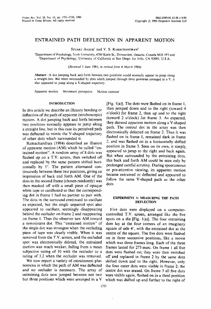
Fig. I. (a) Path deflection illusion. A square matrix of five spots was presented in liame I. followed by the same pattern shifted down and to the right in frame 2. and then shifted up and to the right in frame 3. The central spot was deleted from frame 2 so that it appeared only in frames I and 1. Numbers m spots show order of presentation. Drawing is not to scale: actual dots were tiny (4 min arc) points of light. not disks. The four spots in the surround were correctly seen as jumping along V-shaped trajectories The central unpaired spot also appeared to follow a V-shaped trajectory (dashed arrow), even though it had no partner to pair with in frame 2. If the four surround dots were removed (not shown). the central spot was correctly seen as oscillating horizontally instead of describing a V. (b) Motion contrast Illusion. Display was the same as II except that the central dot was visible in frames I, 2 and 3, jumping along a straight line. Result: the central dot appeared to move along a slight upward V. as shown
diagra~~~ly in (c).
frame 2. The frames were presented in a con- tinuous sequence 1-2-3-2-1-2-3-2. _ _ The outer four dots were seen as jumping back and forth along a V-shaped path, as one would expect. The centre dot was always erased in frame 2, so that it was displayed only in the two extreme positions. However, its perceived motion was deflected or entrained so that it appeared to jump along the same V-shaped path as the other four dots. This illusory deflection was measured by a matching procedure. A sixth dot positioned 9.2” below the centre spot (and thus well re- moved from the main display) moved in parallel with the entraining dots on frames 1 and 3. However, its vertical position on frame 2 could be adjusted up and down by means of a hand- held joystick controlled by the subject, who could set its trajectory continuously from a steep or shallow upward V through a straight line to a shallow or steep downward V. He was instructed to set the trajectory of this matching spot to look like that of the central entrained spot. Opaque screens were arranged to ensure that he could see either the five-spot display or else the matching spot at any given time, but not both at once, so his compa~son judgments had to be made successively, not simultaneously.
The horizontal component of the two jumps (frames l-2 and frames 2-3) was always set to 24 min arc each. However, the entraining spots jumped along a V-shaped path, so they jumped leftwards down to frame 2, then leftwards up to
frame 3 (or up then down for an inverted V). This vertical component of the jumps was ran- domly pre-set on each trial to a value between 28 min arc upwards and 28 min arc downwards. It was this vertical component that the subject matched. The dots, which were each 4 min arc in diameter, were luminous on a black ground, and the display screen was viewed binocularly in a dimly lit room from a distance of 57cm.
Results are shown in Fig. 2(a). Each datum point is the mean of 30 readings (3 subjects x 10 settings), and the vertical bars show the stan- dard error for the 30 pooled readings. Figure 2(a) shows that the vertical deflection entrained into the test spot was approximately half the actual vertical displacement of the entraining spots.
EXPERIMENT 2: MOTION CONTRAST
A small but crucial change was now made in the display, which completely altered the results. On frame 2 the central dot was now not erased, but was made visible at a position along a straight line midway between its position in frames 1 and 3. Whereas the surrounding dots moved along a V, the central dot now moved along a straight line (Fig. I(b)]. Result: the central dot showed an apparent vertical excur- sion opposite to that of the entraining dots. When the entraining dots moved in an upward V the central dot appeared to move in a sli.ght
Entrained path deflection in apparent motion I733
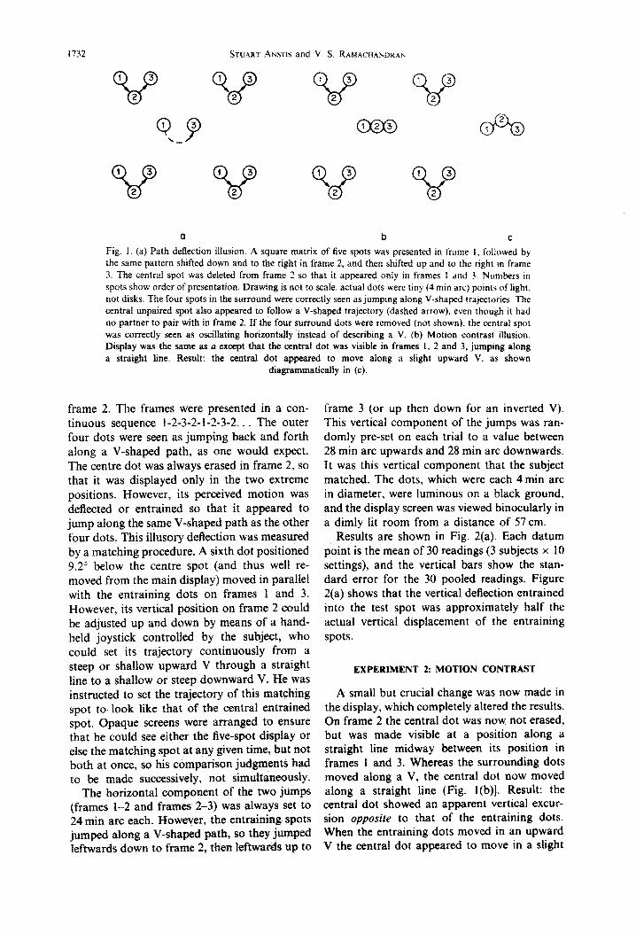
_ 18-
- 27 -18 -9 0 9 18 27 -84 -56 -28 0 28 56 84
Vertical excursion of entramlng dots (min arc)
a b Fig. 2. (a) Path deflection in of the central dot in Experiment I [Fig. t(a)] as a function of the amplitude of the V-shaped trajectories of the four spots in the surround. Each datum point is the mean of 30 readings (3 subjects x 10 readings). Vertical bars show standard errors of the 30 pooled readings. Apparent deflections entrained into the central dot were about half the actual vertical deflections of the surround dots. (b) Motion contrast induced into the central dot in Experiment 2 [Fig. I(b)]. Each datum point is the mean of 6 readings (2 subjects x 3 readings). Apparent deflection of central dot was now opposite to the actual vertical deflection of surround dots. Slope of best fitting line was -0.177. Note that (a) and
(b) have different abscissae.
downward V. When the entraining dots moved in a downward V the central dot appeared to move in a slight upward V. Results are shown in Fig. 2(b). Each of the five datum points is the mean of 6 readings (2 subjects x 3 trials). The least-squares fitted line has a slope of -0.177, which implies that when the entraining dots moved up through I deg the central dot ap- peared to move down through 0.177 deg. Note that the vertical component of the entraining dot motion was varied within a broader range than in Experiment 1.
Thus when the central dot was erased in frame 2 (Experiment 1) its vertical apparent excursion was in the same direction as the surrounding dots (motion assimilation). But when it was made visible in frame 2, midway between its positions in frame 1 and frame 3
(Experiment 2) its vertical apparent excursion was in the opposite direction to the surrounding dots (motion contrast). Motion contrast was approximately a third of motion assimilation.
We shall now leave motion contrast and return to entrained motion.
DEMONSTRATION 3: SPATIAL AND TEMPORAL CHARACTERISTICS OF PATH DEFLECTION
Demonstration 3 shows that path deflection has a finite range both in time and in space, and is not caused by eye movements. The stimulus used isshown in Fig. 3. (a) Temporal loca~isat~on: four dot positio~~ instead of three
In Fig. 1 the entraining dots jumped along a V-shaped trajectory defined by three positions.
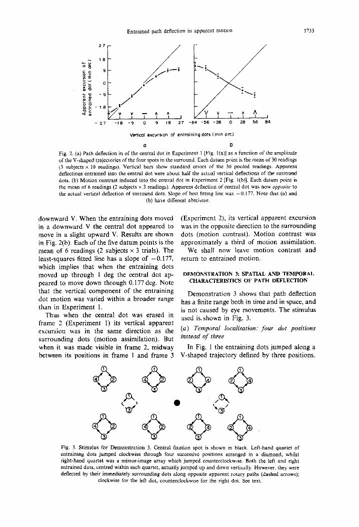
Fig. 3. Stimulus for ~onstration 3. Central fixation spot is shown in black. Left-hand quartet of entraining dots jumped clockwise through four successive positions arranged in a diamond, whilst right-hand quartet was a mirror-image array which jumped counterclockwise. Both the left and right entrained dots, centred within each quartet, actually jumped up and down vertically. However, they were deflected by their immediately surrounding dots along opposite apparent rotary paths (dashed arrows);
clockwise for the left dot, counterclockwise for the right dot. See text.
I734 STUART ANSTIS and V. S. K A M A C H A IW K A X
But in Fig. 3. they jumped along circular or diamond-shaped trajectories defined by four dot positions. The motion of the dot pattern was not rotary, but translatory, according to a trans- latory vector which was uniformly changing its orientation. This circular motion was clockwise in the left half of the field, and counterclockwise in the right half. For simplicity we shall describe what happens in the left half only. The en- trained central dot was visible in frames 1 and 3 but was deleted in frames 2 and 4. On its own it would be seen as jumping back and forth vertically between positions 1 and 3. However. the entraining dots deflected its perceived path so that it appeared to follow the same clockwise rotary path (dashed arrows in Fig. 3) as the entraining dots. Thus the path deflection was localised in time, being apparently leftwards on the up stroke between frames 3 and 1. and rightwards on the down stroke between frames 1 and 3. Hence no long integrating time or buildup time is involved in path deflection.
(b) Spatial localisation: opposite de$ections in direren t spatial regions
The rotary entraining motion was made clockwise in the left half of the field, but coun- terclockwise in the right half of the field. The left and right entrained dots were both made to jump back and forth along parallel vertical trajectories, both being visible only on frames 1 and 3. However, the two entrained dots ap- peared to move along opposite rotary paths, clockwise for the left entrained dot and counter- clockwise for the right entrained dot. Each dot appeared to adopt the trajectory of the dots which immediately surrounded it. This shows that different path deflections could be entrained locally in different spatial regions.
(c) Path deflection is not caused by eye moue- ments
In viewing Fig. 3, subjects were instructed to fixate the stationary central disc. Even if they did not obey this instruction, it is clear that since the eyes obviously cannot roll clockwise and counterclockwise at the same time, eye move- ments can be ruled out as the primary cause of the two opposite path deflections which were simultaneously visible in Fig. 3.
In Experiment 1 and Demonstration 3, the apparent deflections of the AM in the entrained spot were roughly at 45” to the spot’s physical displacement as it jumped from frame 1 to frame 3. So they cannot be simply a form of
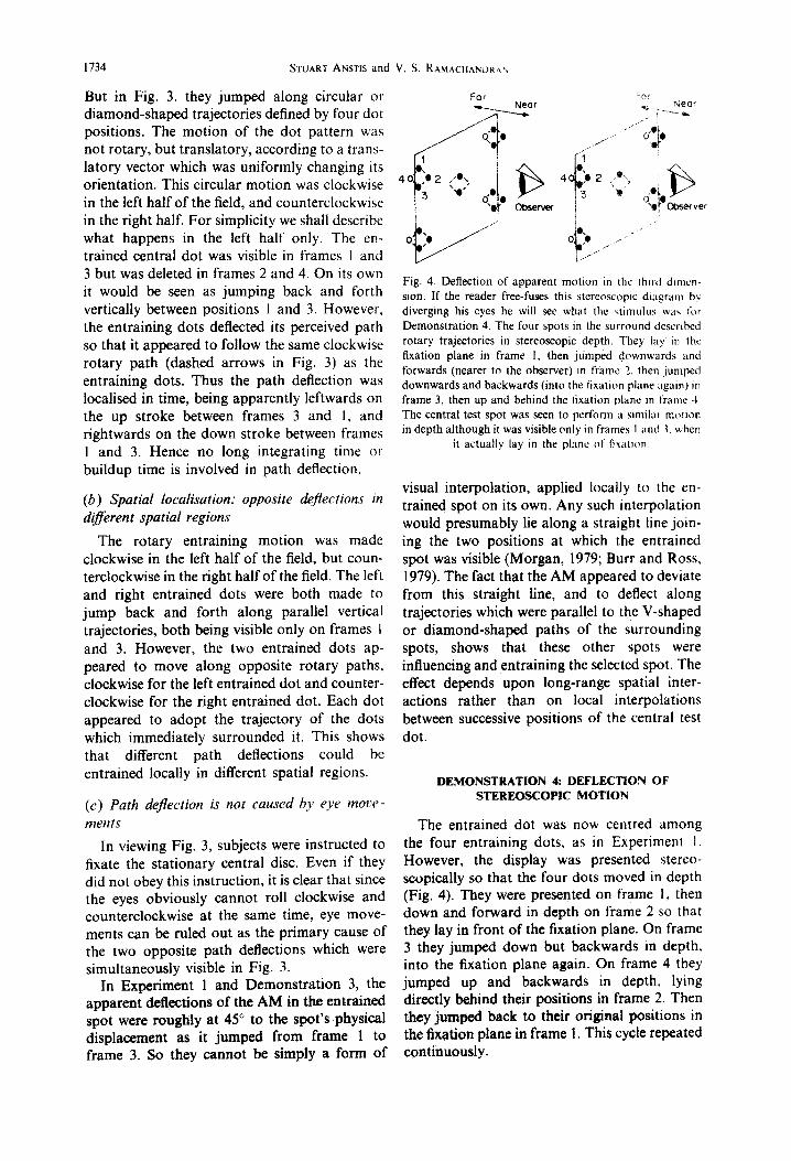
Fig. 4. Deflection of apparent motion in the thucl dlmcn- sion. If the reader free-fuses this stereoscopic diagram bv diverging his eyes he will see what the stimulus \vir\ :bi Demonstration 4. The four spots in the surround described rotary trajectories in stereoscopic depth. They lay in the fixation plane in frame 1, then jumped downwards and forwards (nearer to the observer) in frame 2. then jumped downwards and backwards (into the fixation plane agam) m frame 3, then up and behind the lixation Iilanc in frame J The central test spot was seen to perform a similar moiion in depth although it was visible only in frames I ;~nc! 1. u hen
it actually lay in the plane of fi~rion
visual interpolation, applied locally to the en- trained spot on its own. Any such interpolation would presumably lie along a straight line join- ing the two positions at which the entrained spot was visible (Morgan, 1979; Burr and Ross. 1979). The fact that the AM appeared to deviate from this straight line, and to deflect along trajectories which were parallel to the V-shaped or diamond-shaped paths of the surrounding spots, shows that these other spots were influencing and entraining the selected spot. The effect depends upon long-range spatial inter- actions rather than on local interpolations between successive positions of the central test dot.
DEMONSTRATION 4: DEFLECTiON OF STEREOSCOPIC MOTION
The entrained dot was now centred among the four entraining dots, as in Experiment I. However, the display was presented stereo- scopically so that the four dots moved in depth (Fig. 4). They were presented on frame 1, then down and forward in depth on frame 2 so that they lay in front of the fixation plane. On frame 3 they jumped down but backwards in depth. into the fixation plane again. On frame 4 they jumped up and backwards in depth. lying directly behind their positions in frame 2. Then they jumped back to their original positions in the fixation plane in frame 1. This cycle repeated continuously.
Entrained path deflection in apparent motion 1735
Far Far - --Y’
6 Observer
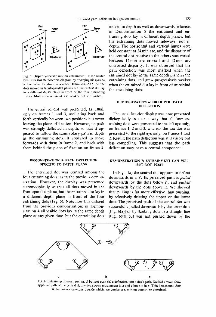
Fig. 5. Disparity-specific motion entrainment. If the reader free-fuses this stereoscopic diagram by diverging his eyes he will see what the stimulus was for Demonstration 5. All the dots moved in frontoparallel planes but the central dot lay in a different depth plane in front of the four entraining
dots. Motion entrainment was weaker but still visible.
The entrained dot was presented, as usual, only on frames 1 and 3, oscillating back and forth vertically between two positions but never leaving the plane of fixation. However, its path was strongly deflected in depth, so that it ap- peared to follow the same rotary path in depth
‘as the entraining dots. It appeared to move forwards with them in frame 2, and back with them behind the plane of fixation on frame 4.
DEMONSTRATION 5: PATH DEFLECTION SPECIFIC TO DEPTH PLANE
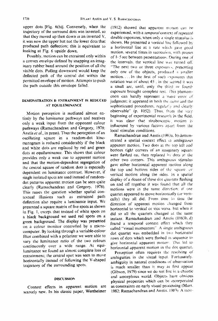
The entrained dot was centred among the In Fig. l(a) the central dot appears to deflect four entraining dots, as in the previous demon- downwards in a V. Its perceived path is pulled stration. However, the display was presented downwards by the dots below it, and pushed stereoscopically so that all dots moved in the downwards by the dots above it. We showed frontoparallel plane, but the entrained dot lay in that pulling is far more effective than pushing, a different depth plane in front of the four by selectively deleting the upper or the lower entraining dots (Fig. 5). Note how this differed dots. The perceived path of the central dot was from the previous demonstration: in Demon- successfully pulled downwards by the lower dots stration 4 all visible dots lay in the same depth [Fig. 6(a)] or by flanking dots in a straight line plane at any given time, but the entraining dots [Fig. 6(c)] but was not pushed down by the
moved in depth as well as downwards, whereas in Demonstration 5 the entrained and en- training dots lay in different depth planes, but the entraining dots moved sideways, not in depth. The horizontal and vertical jumps were held constant at 24 min arc, and the disparity of the central dot relative to the others was varied between 12 min arc crossed and 12 min arc uncrossed disparity. It was observed that the path deflection was most marked when the entrained dot lay in the same depth plane as the entraining dots, and grew progressively weaker when the entrained dot lay in front of or behind the entraining dots.
DEMONSTRATION 6: DICHOPTIC PATH DEFLECTION
The usual five-dot display was now presented dichoptically in such a way that all four en- training dots were presented to the left eye only, on frames 1, 2 and 3, whereas the test dot was presented to the right eye only, on frames 1 and 2. Result: the path deflection was still visible but less compelling. This suggests that the path deflection may have a central component.
DEMONSTRATION 7: ENTRAINMENT CAN PULL BUT NOT PUSH
a b C
Fig. 6. Entraining dots can pull (a, c) but not push (b) a deflection into a dot’s path. Dashed arrows show apparent path of the central dot, which shows entrainment in a and c but not in b. Thin line around dots
is the convex envelope outside which, we conjecture, motion cannot be entrained.
1736 STUAKT ANSTIS and V. S. RAMACHANUKA~
upper dots [Fig. 6(b)]. Conversely, when the trajectory of the surround dots was inverted, so that they moved up then down in an inverted V, it was now the upper but not the lower dots that produced path deflection; this is equivalent to looking at Fig. 6 upside down,
Possibly, motion can be entrained only within a convex enz:e@e defined by snapping an imag- inary rubber band around the position of at1 the visible dots. Pulling downward would keep the deflected path of the central dot within the permitted envelope of motion. Attempts to push the path outside this envefope failed.
DEMONSTRATION 8: ENTRAINMENT IS REDUCED
AT EQUILUMINANCE
Motion perception is mediated almost en- tirely by the luminance pathways and receives only a weak input from the opponent cofour pathways (Ramachandran and Gregory, 1978; Anstis et al., in press). Thus the perception of an oscillating square in a random-dot kine- matogram is reduced considerably if the black and white dots are replaced by red and green dots at equiluminance. This shows that colour provides only a weak cue to apparent motion and that the motion-dependent segregation of the central square of random dots is especially dependent on luminance contrast. However, if single isolated spots are used instead of random- dot patterns apparent motion can be seen quite clearly (Ramachandran and Gregory, 1978). This raises the question whether spatial con- textual illusions such as entrained path deflection also require a luminance input. We presented a square matrix of five spots as shown in Fig. 1, except that instead of white spots on a black background we used red spots on a green background. The display was presented on a colour monitor controlled by a micro- computer. By Iooking through a variable-colour filter combined with a polarizer we were able to vary the luminance ratio of the two colours continuously over a wide range. At equi- Iuminance we found an almost complete loss of entrainment; the central spot was seen to move horizontally instead of following the V-shaped trajectory of the surrounding spots.
DISCUSSION
Context effects in apparent motian are scarcely new. In his classic paper, Wertheimer
(1912) showed that apparent rnorion c:i~n :X experienced, with a temporalcontext of repeated double exposures, when only ;J, single stimulus ix shown. He presented a vertical line followed by a horizontal line at a rate whi!_h gave good motion, several times in successioil. with pauses of l-5 set between presentations. During out: &’ the intervals. the vertical line LS#;L:, turned on’. “The next two or three exposu~~.,~. presenting only one ot’ the objects. protlt~ti ;I smaller motion. . In the first of sucn i’tposures ihis rotation was of about 45‘. in the second it wris a small arc, until, only the third or fourth exposure brought complete rest. I’his phenom- cnon can hardly represent ;I fltt:rc error oi” judgment: it appeared in both rhe r~aive and rhc! sophisticated procedures. regular,! XKI c!eari;,~ observable” (p. 1052). Thus. ftom the cerj’ beginning of experimental researcll in the field. it was clear that stroboscopic, motion i.i influenced by various factors ap;xrt from the local stimulus conditions.
Ramachandran and Anstis (i PXSa. b) demon- strated a spatial context effect L;I ambigu~~us apparent motion. ‘two dots at rh:., top left and bottom right corners of an imaginary square were ffashed on, then replaced hv dots at ihc other two corners. This ambtguaus stimulus gave either horizontal apparent motion along the top and bottom sides of the i;quare. (13 vertical motion along the sides. In a spatial display of a dozen of these dot quartets fIashing on and off together it was found that all the motions were in the same diret.?ion; it’ one quartet appeared to move horizontally (or vertt- tally) they all did. From time io time the direction of apparent motion <hanged from horizontal to vertical or vice vet-s:%. hut when it did so all the quartets changed a1 the same instant. Ramachandran and Anstii (I 983b d) found a temporal context cffeec! which they called “visual momentum“. A single ambiguous dot quartet was embedded in tivo horizontal rows of dots which were hashed II: sequence it? give horizontal apparent motion, ‘I’his led to horizontal apparent motion in the dot quartet.
Perception often requires the resolving of ambiguities in the visual input. Fortunately, ambiguity in natural conditions of observation is much smaller than it may at first appear (Gibson, 1979) since we do not iive in a chaotic and amorphous world. Objects i~ave obvious physical properties which can be mcorporated as constraints on early visual processing (Marr, 1982; Ramachandran and Anstis, 19831. A move-
Entrained path deflection in apparent motion 1737
ing object, for instance, usually has surface rigidity. Consequently all features of the object will tend to move in the same direction with nearly identical velocities. The entrained motion illusion may be a perceptual manifestation of surface rigidity, such that in ambiguous situ- ations the brain may adopt constraints that result in a preference for uniform motion over incoherent motion.
Although it is plausible to expect this illusion, given the statistical properties of the real world, the mechanisms underlying it need further study. We discuss four points of view: (1) object conservation, (2) occlusion/disocclusion, (3) attention failure, and (4) cooperative parallel algorithms. These possibilities need not be mutually exclusive.
(i j object conservation
It is well known that when we view a single spot exposed in two successive positions, we perceive a single motion rather than two succes- sive but unrelated events. The reason has been well put by Shepard and Zare (1983):
“This phenomenon [of apparent motion] pro- vides evidence for the internalization of prin- ciples of object conservation and least action. The brain evidently prefers the interpretation that a persisting object moved over the most direct path consistent with the available evi- dence rather than an interpretation that the object moved over some longer path or, worse, that one object went out of existence and a second object simultaneously materalised at another location”.
Thus when a spot disappears at one position and another nearby spot promptly appears, the brain treats this as not just a coincidence but as a pair of connected events. In the same way, when five spots disappear simultaneously (after frame 1) and reappear SimuItaneously (in frame 3), this is also treated as not just a coincidence. Although the centre dot behaves differently from the others on frame 2 it is perceived as moving with the other dots. In our opinion, path deflection arises from the same principle of least action that causes us to see apparent motion of a single dot in the first place. When a central spot jumping from position 1 to posi- tion 3 is surrounded by a quartet of dots with each jump from 1’ to 2’ to 3’, the brain adopts the economical hypothesis that all the spots move together like a rigid surface, rather than that four dots move along one trajectory while
the central spot coincidentally happens to move along a different, linear trajectory. We might say that the brain abhors a coincidence and loves a common cause.
The rectilinear path of the central spot should be considered not as a local interpolation but simply as the default trajectory in the absence of more information. Shepard and Zare (1983) added a curved gray path, briefly flashed be- tween two alternately displayed black dots. This induced the illusion of a single dot moving back and forth over that path. In our experiment. on the other hand, the extra information came from the V-shaped trajectories of the sur- rounding dots some distance away. This offered contextual evidence that the central dot’s path was longer than a direct straight line, and the invisible central spot at position 2 provided no direct evidence against this; so the observer perceived all five spots as following parallel V-shaped paths.
An entrained dot (Ramachandran, 1984) dis- appears behind an occluder, but the central dot in our display seems to move even when no occluder is present. Sigman and Rock (1974) also explored the role of occlusion in apparent motion. They propose that the perception of apparent motion can be the outcome of an intelligent problem-solving process. They exposed two spots a and b in alternation, by moving an opaque rectangle back and forth, alternately covering and uncovering two sta- tionary spots a and b, in the right places and tempo that ought to give good apparent motion. As far as other theories of apparent motion are concerned, there is no reason why these condi- tions should not produce an impression of a and b moving. But from the standpoint of problem- solving theory, the moving rectangle provided an explicable basis for the appearance and disappearance of a and b, namely that they are there all the time but are undergoing covering and uncovering. This is what the subjects re- ported; they rarely reported apparent motion. However, if the rectangles were drawn so as to look transparent they did not look capable of covering anything, so it was no longer a fitting or intelligent solution to perceive a and b as two permanently present dots that were simply un- dergoing covering and uncovering. In this con- dition, subjects again reported apparent motion (Rock, 1983).
1738 STUART ANSTIS and V. S. KAMAC~HANI)K,+.
Clearly occlusion/disocclusion is an attractive explanation for simple entrained motion (Ramachandran, 1984). The entrained dot, which flashes on and off next to an opaque piece of card, is perceived as jumping back and forth, going behind the card then emerging again. This phenomenon is the converse of the effect de- scribed by Sigman and Rock (1974) who moved a card back and forth and found that dots which would otherwise have been seen as moving were now seen as stationary. Ramachandran kept the occluder stationary and provided a context of jumping dots, and found that a flashing dot which would otherwise have been seen as sta- tionary was now seen as moving. In Rock and Sigman’s experiment the motion of the occluder vetoes the motion signal from the spots. In Ramachandran’s experiment the static occluder allows a motion signal to be seen; a signal that would otherwise be rejected by the brain.
We regard path deflection as a form of entrained motion. However, it is a stronger illusion, and in particular it needs no occluder. We believe the reason is that in entrained mo- tion the brain must extrapolate from one seen position of the entrained dot to a second, unseen position, whereas in path deflection it has merely to interpolate between two seen posi- tions to a third, unseen intermediate position. Perhaps disembodied motion signals are not accepted unless the motion can be attributed to a visible object or feature. Ramachandran (1984) reported that without the occluder. no second dot existed to carry the motion, but with the occluder present the observer could assume that the dot had now hidden behind it, so the illusion was considerably enhanced. In deflected motion, the unpaired spot reappeared in the third frame so the visual system could confidently attribute the motion signal to this reappearing spot ,
On the other hand, when the central spot is visible at three positions in line (Experiment 2) it does provide direct evidence countermanding the hypothesis of entrainment, which is con- sequently rejected. Now a different phenom- enon came into play: The rectilinear path of the central spot now appeared bent in the opposite direction from the surround because of motion contrast, a process akin to induced movement. Motion contrast has been reviewed by Anstis (1986). Whereas occlusion may be involved in motion assimilation or entrainment, it plays no part in motion contrast since the central dot remained visible and unoccluded at all times.
(3) Attention ,fdure
Treisman and Schmidt (1982) have suggested that in perceiving objects we may integrate separable features, such as colour and shape, bl directing attention serially to each item, TI! accord with this feature-integratmr theory. they found that when attention was diverted or ovcr- loaded. features were sometimes wrongly x- combined. giving rise to “illusory conjunc- tions”. For instance, when a card exhibiting ‘1 pink X and a green T was flashed up briefly. observers often clearly saw a punk T 11 I& arguable that object movement might be such a separable feature. so that (17 the visuai processing of motion there may be a partia”i separation between object identity and object motion. Thus the question of which ob,ject moved may not be synonymous r+irh where in the visual field the motion nicurred. The “where” question may be answered by a global motion detector that sees motion averaged over the whole of the dot cluster. The motion signal thus derived is then attributed to all the finer image features as well- including the smgle unpaired dot. Ramachandran and lnada (1985) have called this effect “motion capture”.
But we doubt that path deflection is caused by attention failure. Attention can fail for two reasons: pre-attentive processing timits in the visual system, or attentional load applied by a difficult task. Neither seems to apply to our experiments. In normal viewing we very rarely misattribute colors or motion; we seldom per- ceive a green rose with red leaves, and we rarely perceive the wrong part of the scene as moving, except perhaps in difficult viewing conditions such as seeing a leopard moving behind fluttering foliage. (We do sometimes mis- attribute motion, for instance when the moon seems to sail behind drifting clouds or the river bank seems to swirl upwards after we have gazed at a waterfall. But induced movement and the motion aftereffect probably involve in- hibitory interactions between motion sensing channels, and have nothing to do with illusory conjunctions or the overloading of attention,) So in normal viewing conditions color and motion perception are not constrained by pre- attentive processing limits; errors of illusory conjunction arise only when attention is over- loaded, for instance by the brief tachistoscopic exposures used by Treisman and Schmidt (1982). But we never used brief exposures or difficult viewing conditions; our observers were free to inspect the display for as long as they
Entrained path deflection in apparent motion 1739
wished, yet the path deflection phenomenon,was clearly seen. We conclude that there is little evidence that either attentional load or pre- attentive processing limits play a role in path deflection.
Motion may be analysed by the same types of co-operative parallel algorithms as are used to analyse global stereopsis in random-dot stereo- grams (Julesz, 197i; Sperling, 1970; Dev, 1975; Nelson, 1975; Marr, 1982). Units tuned to sim- ilar directions and velocities may facilitate each other and thereby reduce or eliminate spurious signals of incoherent motion based on potential false matches.
In summary, the four mechanisms postulated to process object identity and object motion separately are consistent with several aspects of both versions of entrained motion.
Acknowledgements-S.M.A. was supported by Grant A 0260 from NSERC (Canada). We thank Ebbe Ebbeson of the Unjversity of California at San Diego for facilities and D. I. A. Macleod, F. Crick, J. A. Deutsch and our two anonymous referees for helpful comments and discussions.
REFERENCES
Anstis S. M. (1986) Motion in the frontal plane: sensory aspects. in ~~n~oo~ of Perception (Edited by Kaufman L. and Boff K.). In press.
Anstis S. M., Cavanagh P., Maurer D., Lewis T. and Mather G. (1986) Computer-generated screening test for color blindness. Color Res. Applic. In press.
Burr D. C. and Ross J. (1979) Acuity for apparent vernier offset. Vision Res. 19, 523-532.
Dev P. (1975) Perception of depth surfaces in random-dot stereograms: A neural model. Int. J. ~an-~a~~ine Stud. 7, 51 I-528.
Gibson J. J. (1979) The Ecological Approach to Visual Perception. Houghton Mifflin, Boston.
Julesz B. (1971) Foundations cf Cyclopean Percepzion. Univ. of Chicago Press.
Marr D. (1982) Vision. Freeman, San Francisco, Calif. Morgan M. J. (1979) Analogue models of motion percep-
tion. Phil. Trans. R. Sot. Lond. B 290, 117 135. Nelson J. 1. (1975) Globality and stereoscopic fusion in
binocular vision. J. theoret. Biol. 49, l-88. Ramachandran V. S. (1984) Entrained motion: A new
visual illusion. Invest. Ophthal. &ual Sci., Suppl. 25, 200 (Abstr.).
Ramachandran V. S. and Anstis S. M. (1983a) Perceptual organization in moving displays. Nazure 304, 829-831.
Ramachandran V. S. and Anstis S. M. (1983b) Extrapo- lation of motion path in human visual perception. Vision Res. 23, 83--85.
Ramachandran V. S. and Gregory R. L. (1978) Does colour provide an input to motion perception? ilitture 275, 55-57.
Ramachandran V. S. and Inada V. (1985) Spatial phase and frequency in motion capture of random-dot patterns. spatial Vision 1, 55.-67.
Rock I. (1983) The Logic of Perception. MIT Press, Cambridge.
Shepard R. and Zare S. (1983) Path-guided apparent motion. Science 220, 632634.
Sigman E. and Rock I. (1974) Stroboscopic movement based on perceptual intelligence. Perception 3, 9-28.
Sperling G. (1970) Binocular vision: A physical and neural theory. Am. 1. P.Tychol. 83, 461-534.
Treisman A. and Schmidt H. (1982) Illusory conjunctions in the perception of objects. Cogn. Ps$zoi. 14, 107-141.
Wertheimer M. (1912) Experimentelle Studien uber das Sehen von Bewegung. Translated in part as: Experi- mental studtes on the seemg of motion. In Classics in Psychology (Edited by Shipley T.), pp. 1032-1089. Philosophical Library, New York, 1961.