ensc 427 communication networks spring 2012ljilja/ensc427/spring12/projects/team10/final... · ensc...
TRANSCRIPT
VoIP in NS2 SimulationConnecting the world
one node at a time
Ensc 427 Communication NetworksSpring 2012Web Address: http://www.sfu.ca/~bja7/Group 10Behdad Jamshidi – 301068521([email protected])Victor Mateescu – 301071298 ([email protected])

VoIP in NS2 SimulationConnecting the world
one node at a time
Page: 2
Table of ContentsAbstract ............................................................................................................................................................................................ 3
Introduction...................................................................................................................................................................................... 3
Background....................................................................................................................................................................................... 3
VoIP Advantages .......................................................................................................................................................................... 3
Voice over TCP ............................................................................................................................................................................. 3
Voice over UDP ............................................................................................................................................................................ 4
Voice over RTP ............................................................................................................................................................................. 4
Implementation ................................................................................................................................................................................ 5
Simulation with NS-2 ................................................................................................................................................................... 5
Filtering the Trace File with AWK................................................................................................................................................. 6
Parsing and Plotting with MATLAB .............................................................................................................................................. 7
Throughput ............................................................................................................................................................................. 7
Packet Loss.............................................................................................................................................................................. 7
End-to-End Delay .................................................................................................................................................................... 7
Jitter ........................................................................................................................................................................................ 8
Results and Discussion...................................................................................................................................................................... 9
VoIP using UDP: ........................................................................................................................................................................... 9
Throughput ............................................................................................................................................................................. 9
Delay ..................................................................................................................................................................................... 10
Packet Loss............................................................................................................................................................................ 11
Jitter ...................................................................................................................................................................................... 12
VoIP using TCP ........................................................................................................................................................................... 12
Throughput ........................................................................................................................................................................... 12
Delay ..................................................................................................................................................................................... 13
Packet Loss............................................................................................................................................................................ 13
Jitter ...................................................................................................................................................................................... 15
VoIP using RTP ........................................................................................................................................................................... 15
Conclusion ...................................................................................................................................................................................... 15
References ...................................................................................................................................................................................... 16
Appendix A: NS-2 Code ................................................................................................................................................................... 16
UDP: ........................................................................................................................................................................................... 16
TCP: ............................................................................................................................................................................................ 20
RTP: ............................................................................................................................................................................................ 24
Appendix B: MATLAB Code ............................................................................................................................................................. 29

VoIP in NS2 SimulationConnecting the world
one node at a time
Page: 3
AbstractDue to the recent technological advancement in packet switching networks, VoIP (Voice over InternetProtocol) has become an industry favorite over Public Switching Telephone Networks (PSTN) withregards to voice communication. The cheap cost of making a call through VoIP internationally andpaying just one bill for data usage is a huge benefit. Recently, Rogers has taken advantage of VoIP withtheir Rogers one number promotion where calls can be transferred and made through your computer.Although, there are huge advantages to using VoIP there are some known issues such as, packet loss,jitter and latency due to the connection through the computer internet. Our project consists of creatinga VoIP network (in NS2-2.35) and testing for its known faults. Through this we want to get a betterunderstanding of the underlying layers of the network and see if and where improvements can be made.
IntroductionFor this project we are using NS2 to implement our VoIP network. We will be setting up several nodeson either side of two routers. We are going to be using an exponential traffic source to re-create atypical voice conversation over VoIP. Different protocols will be used to send voice information betweenterminals, starting with User Datagram Protocol (UDP), Transmission Control Protocol (TCP), and Real-time Transport Protocol (RTP). We are going to be measuring packet loss, throughput, end-to-end delay,and if the protocol permits, jitter. We will be plotting our results and comparing them to our theory-based predictions.
Background
VoIP AdvantagesVoIP offers several advantages over traditional circuit switching networks. These include:
Low cost: Utilizes the widespread availability of Internet to make phone calls using standard,readily available computer parts.
Integrate different web services with VoIP: An example would be calling a retail establishmentwhile online shopping directly from your computer to make product inquiries.
Possibility for greater bandwidth efficiency: Due to the vast amounts of codecs available forVoIP networks (which may also be available to circuit-switching networks but are notimplemented due to cost restrictions), voice data may be transmitted at rates different from thestandard 64kbps, including variable bit rates [1].
Voice over TCPSince IP is a best-effort protocol, it does not prevent errors such as packet loss from occurring. TheTransmission Control Protocol (TCP) serves to mitigate this flaw by detecting errors, retransmitting lost

VoIP in NS2 SimulationConnecting the world
one node at a time
Page: 4
packets, and ensuring data is ordered properly in order to provide reliable service. TCP is a connection-oriented protocol that lies in the Transport layer. The connection is formed via a handshake betweentwo hosts with connection requests and acknowledgments. Once the connection is formed, the databeing transmitted is broken into segments. Before the segment is transmitted, a header is attachedwhich contains a sequence number. The receiver will respond to the arriving packet with anacknowledgement if no errors are found. If no acknowledgement arrives at the original sender after acertain timeout period, the sender will re-transmit the packet [4].
Despite its reliable service, the main drawbacks of TCP are the long delays inherent in taking suchpreventative measures. One of the main challenges of VoIP is the delay restriction in a real-time phonecall. According to the ITU-T Recommendation G.114, one-way delay should be no more than 400milliseconds for international calls [5]. However, maintaining constant high quality audio during thephone call is also an important aspect – one that is challenged by packet loss and errors duringtransmission. In general, large delays are more undesirable than data loss with regards to voicecommunications due to the “real-time” aspect. Investigation of a TCP-based VoIP network is necessaryto determine how much of a benefit the added reliability is at the cost of longer delay times.
Voice over UDPThe UDP is a simple protocol that passes data along from the application layer to IP to be transmitted. Itperforms none of the error checks that TCP does, and is therefore unreliable. A UDP header merelyconsists of an optional source port, a destination port, the length of the datagram, and a checksum [4].As previously mentioned, the main reason for using UDP over TCP in VoIP applications is the reduceddelay. In general, the sporadic loss of packets in a conversation will not be as disruptive as excessivelylong delay times. In fact, a packet loss of about 5% is said to be tolerable depending on how the lossesare distributed [1]. We will investigate how well a UDP-based VoIP network performs in contrast to itsTCP counterpart.
Voice over RTPThe RTP is an application layer protocol that attaches itself to UDP to provide added benefits for real-time applications. An RTP header includes a sequence number to help preserve the order of thetransmitted packets. It also includes a timestamp, which is meant to provide information to thedestination application so that it may compensate for problems such as delay or jitter if they arise. Theoptional companion protocol, RTCP (specified in RFC 3550), is used as a means of exchanginginformation on session quality, which can include the number of lost packets or the average delay time[2].
RTP strikes a balance between UDP and TCP for VoIP applications. It is designed to operate rapidly likeUDP and it provides the receiver with valuable information pertaining to the VoIP session. The receivingapplication can then use this information to alleviate problems caused by out-of-sequence packets andjitter, thus improving the quality of the session. RTP is the protocol of choice for streaming media overthe Internet and is widely used in VoIP applications [2].

VoIP in NS2 SimulationConnecting the world
one node at a time
Page: 5
Implementation
Simulation with NS-2In a standard circuit-switching network, an analog voice signal must be sampled at twice its maximumfrequency at 8 bits per sample. Standard human speech reaches about 4000kHz, thus a bandwidth of64kbps is required. The advancement of codec technology has improved bandwidth efficiency intelephony by only transmitting information when a person is talking [1]. Therefore, a variable bit rate oneach end is required to accurately simulate a VoIP call.
In our implementation, we assume the commonly used G.711 codec, which transmits information at arate of 64kbps [2]. The size of the transmitted packets was chosen to be 128 bytes for UDP. TCPpayloads are 1040 bytes and the ACK packets are 40 bytes. The phone call is established between Nodes0 and 4 as shown in Figure 1. Node 0 transmits data with an average “on” time of 1200ms and idle timeof 800ms. Node 4 is setup to transmit fewer packets over the 60 second simulation with an average “on”time of 800ms and idle time of 1200ms.
Figure 1: NS-2 implementation of a VoIP network
The scale of the simulation was chosen to be nation-wide, thus the link between routers represented byNode 8 and 9 was chosen to be an Optical Carrier Level-1 (OC-1) line, which has a bandwidth of51.84Mbps [4]. The link used in the simulation is a duplex link and thus has its bandwidth set to25.92Mbps to properly mimic the OC-1 and a delay of 35ms, which is the end-to-end delay of a ping sentfrom Vancouver to Toronto.
The background traffic of the network is supplied by Nodes 1, 2, 3, 5, 6, and 7 at constant bit rates. Asthe simulation begins, Nodes 1 and 5 create background traffic at a rate of 25.89Mbps each (while allother background sources are turned off), providing a sub-maximal load for the duplex link between thetwo routers. Then from 20s to 40s, Nodes 2 and 6 are turned on (while Nodes 1 and 5 turn off) to

VoIP in NS2 SimulationConnecting the world
one node at a time
Page: 6
provide background traffic of 25.91Mbps each. This was chosen to slightly overload the link’s capacityand thus cause congestion within the network. Finally, when the simulation reaches 40 seconds, Nodes3 and 7 are tasked with providing the background traffic at a rate of 25.92Mbps each, greatly exceedingthe network’s bandwidth. At this point, it is expected that the queues become full and resulting in manydropped packets.
Depending on our simulation, UDP, TCP, or RTP agents were attached to Nodes 0 and 4. For thebackground traffic, we used UDP for all three scenarios. Furthermore, Traffic from Node 0 to Node 4 iscolor coded as blue, whereas traffic from Node 4 to Node 0 is color coded as red. The simulation can bevisualized in NAM.
Filtering the Trace File with AWKThe NS2 code opens an output trace file, out.tr, and records every single event of the simulation foreach individual packet, such as entering queues or being dropped. An important step in identifying thedata pertaining to the phone call itself is to assign unique flow IDs – packets transmitted from Node 0have a flow ID of 1, while packets transmitted from Node 4 have a flow ID of 2.
The NS-2 trace file is structured in columns as follows:
1. Event type “+”: packet enters queue “-“: packet leaves queue “r”: packet received “d’ packet dropped
2. Timestamp3. Source Node4. Destination Node5. Packet Type (ie: “exp” for the variable bit rate used to simulate the call)6. Packet Size7. Flags (unused)8. Flow ID9. Source Address10. Destination Address11. Sequence Number12. Unique Packet ID
A 60 second simulation with such a large amount of background traffic could result in trace files that arehundreds of MBs large, making parsing impossible. Since we are only interested in the data pertaining tothe VoIP session between Nodes 0 and 4, the trace file is filtered using an AWK command:
awk '$8==1 || $8==2' out.tr > out.txt

VoIP in NS2 SimulationConnecting the world
one node at a time
Page: 7
This command takes lines containing flow ID 1 or 2 and transfers them to a new file.
Parsing and Plotting with MATLABThe filtered output file is then parsed with MATLAB, by saving the data in each column into differentvectors. This data can then be used to calculate and plot throughput, packet loss, end-to-end delay, andjitter. The main challenge is the fact that these measurements must be done based on intervals of time;however, the trace file only tracks events the exact moment when they occur and so the data inside thefile is not listed at equal time intervals. Therefore, all calculations done in MATLAB must be based on thevector indices of the parsed data. For example, we wish to make measurements at 2 second intervals.For the interval 2 to 4s, we scan the timestamp vector, time, to find the first index i1 where time[i1] ≥ 2and similarly we find first index i2, where time[i2]≥ 4. Thus, indices i1and i2 essentially correspond to thebeginning and end of a time interval, respectively. These indices are then used as upper and lower limitswhen scanning all other vectors necessary to compute our desired quantities.
ThroughputIn the case of data transmission from Node A to Node B, throughput refers to the total amount of data,measured in bytes/sec, received at Node B. As an example, for our simulation Node 0’s throughput wasmeasured in kbps as follows:
Throughput = Bytes Received∆ × 10 (1)
The event type “r” in the first column of the trace was the primary tool used to track throughput.
Packet LossPacket loss is simply a measure of the amount of packets that are dropped at any point as they travelfrom Node A to Node B. Two measures were taken: one of instantaneous packet loss which describeshow many packets are lost at each time interval and the other of cumulative loss which describes thetotal number of packets lost throughout the simulation. The main tool in tracking the loss of packets wasthe event type “d” in the first column of the trace file.
End-to-End DelayEnd-to-end delay is the time it takes for a packet to travel from Node A to Node B. The end-to-end delayis measured as follows:
1. Obtain the time when a packet is created/transmitted2. Obtain the time when the same packet reached its destination3. Take the difference of the two times
To implement this procedure, first we find the time when the packet is created by checking for eventtype “+” at the node of creation. The unique packet ID specified in column 12 must be saved and a newsearch for the same packet ID with the event type “r” is performed, yielding the received time. The delay

VoIP in NS2 SimulationConnecting the world
one node at a time
Page: 8
is then calculated as mentioned and the next packet with event “+” at the node of creation is found,thus repeating the process. The procedure is performed for all transmitted/received packets within atime interval and the resulting differences are averaged.
JitterJitter, also more formally known as IP Packet Delay Variation (IPDV), is defined as the difference in end-to-end delay of the transmitted packets. There are numerous ways of calculating this quantity.
Figure 2: Illustration of packets with varying end-to-end delays
RFC 3393 suggests a simple method: An interval of time is selected where the first packet P1 and lastpacket PNtransmitted during that interval have delay times of Δt1 and ΔtN, respectively. The jitter is thengiven by ΔtN - Δt1[3].
RFC 1889 suggest another method as shown below (this is also referenced in RFC 3393):= + , (2)
where J is the IPDV as calculated using the simple method mentioned above [3]. Due to the heuristicbasis of (2), we have decided not to measure jitter this way. Instead we use the simple method from RFC3393 mentioned above except instead of finding the difference between the delay of the first and lastpacket of each time interval, we find the difference in delay between each adjacent packet of in aninterval and take an average.
Jitter = ∑ ∆ − ∆− 1 (3)

VoIP in NS2 SimulationConnecting the world
one node at a time
Page: 9
Results and Discussion
VoIP using UDP:
Figure 3: VoIP simulation using UDP in NAM
ThroughputInitially, we see a throughput of 64kbps. As expected, with increase in background traffic, we see a dropin throughput from both ends. At around 30 seconds, the background traffic is taking up a large portionof the bandwidth and so a large decrease in throughput is observed from Node 0 to Node 4. The largespike on the plot to the right at 40 seconds occurs because the user at Node 0 is not talking and thus nottransmitting any data. This frees up a lot of bandwidth so that the user at Node 4 is able to transmit welldespite the heavy background traffic

VoIP in NS2 SimulationConnecting the world
one node at a time
Page: 10
Figure 4: UDP throughput
DelayThe delay for UDP is around 90ms which is well below the recommended limit of 150ms specifiedearlier. We note that the delay varies very little regardless of increasing background traffic.
Figure 5: UDP end-to-end delay

VoIP in NS2 SimulationConnecting the world
one node at a time
Page: 11
Packet Loss
Figure 6: UDP packet loss for data sent from Node 0 to Node 4
As the simulation reaches about 10 seconds, we begin to see some packet losses due to the suddencongestion caused by a combination of background traffic and both users speaking at the same time.The background traffic is upped at 20 seconds and we begin to see the consequences at around 30seconds with the dramatic increase of lost packets. At this point, the queues are growing exceedinglylarge causing many packets to be dropped. Since the background traffic remains constant, the queuesdon’t have time to relieve themselves and as the background traffic is further increased, more packetsare consistently dropped. A total of about 900 packets are lost on their way from Node 0 to Node 4 anda total of 300 are lost from Node 4 to Node 0. For reference, a total of 3603 packets are sent from Node0 to Node 4 and a total of 2008 are sent from Node 4 to Node 0.
Figure 7: UDP packet loss for data sent from Node 4 to Node 0
VoIP in NS2 SimulationConnecting the world
one node at a time
Page: 12
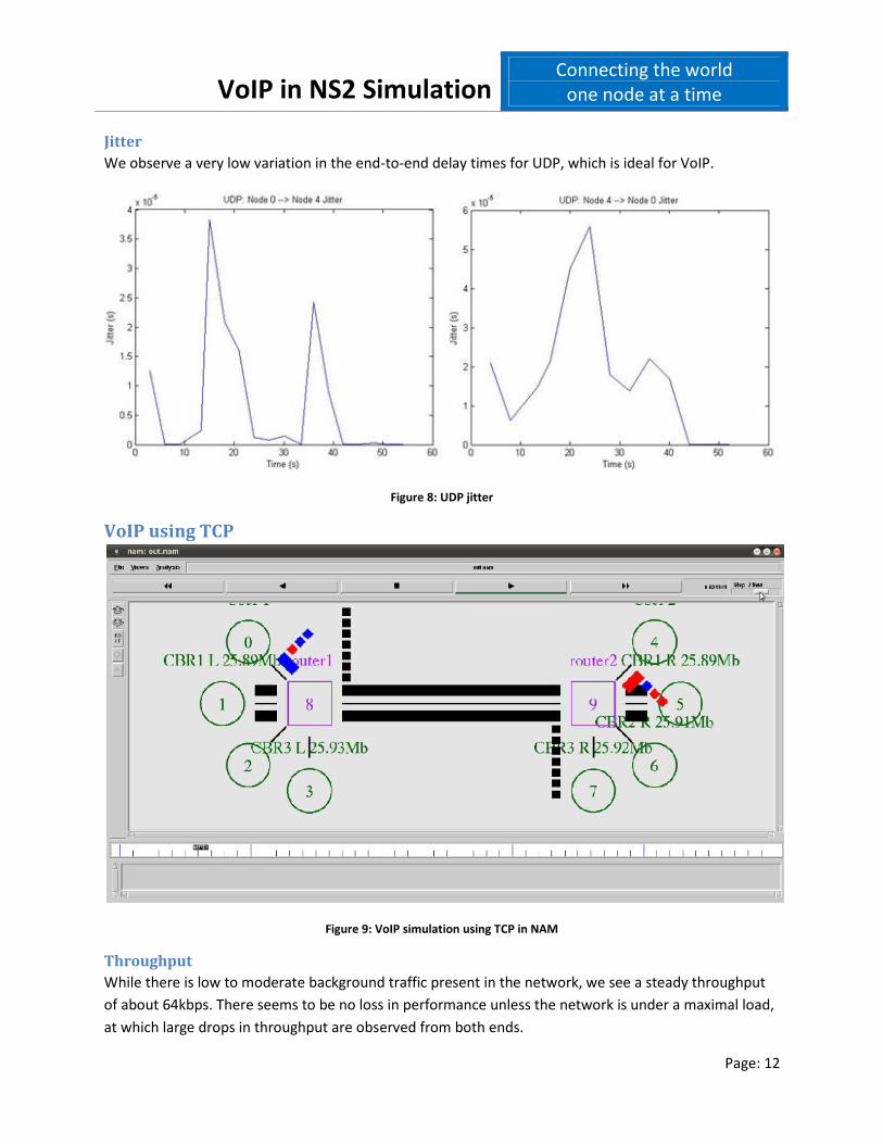
JitterWe observe a very low variation in the end-to-end delay times for UDP, which is ideal for VoIP.
Figure 8: UDP jitter
VoIP using TCP
Figure 9: VoIP simulation using TCP in NAM
ThroughputWhile there is low to moderate background traffic present in the network, we see a steady throughputof about 64kbps. There seems to be no loss in performance unless the network is under a maximal load,at which large drops in throughput are observed from both ends.

VoIP in NS2 SimulationConnecting the world
one node at a time
Page: 13
Figure 10: TCP throughput
DelayLarge delays varying from 0.4 to 1.4 seconds are observed, which greatly exceeds the recommendationof 150ms and even the limit of 400ms for national calls.
Figure 11: TCP delay
Packet LossFor the first 40 seconds of simulation, we do see a fair bit of dropped packets; however, since thethroughput did not drop during this interval, we may conclude that the only packets lost are ACKpackets, which are small in size and are not of real concern. Packets containing actual voice data are lostonly after 40 seconds of simulation when the network is under a maximal load. We see a total of about

VoIP in NS2 SimulationConnecting the world
one node at a time
Page: 14
20 voice data packets lost from both end. A total of 310 packets containing voice data are sent fromeach end.
Figure 12: TCP packet loss for data sent from Node 0 to Node 4
Figure 13: TCP packet loss for data sent from Node 4 to Node 0

VoIP in NS2 SimulationConnecting the world
one node at a time
Page: 15
JitterVery large delay variation is observed, growing exceedingly larger as the simulation progresses.
Figure 14: TCP jitter
VoIP using RTPThe performance of RTP is identical to that of UDP in every aspect. As previously mentioned, RTP merelyattaches additional data to the UDP stream to provide valuable information to the application at theother end. It does not directly prevent issues such as jitter, however the information it provides canwarn the application that such issues are present so that the application can take whatever preventativeactions it needs to.
ConclusionWith regards to our criteria of low packet loss to maintain a high voice quality, we see that TCP out-performs UDP/RTP. Packet losses were not observed for TCP unless the background traffic was atmaximum load. Afterwards, only about 20 packets were dropped out of a total of 310 sent which resultsin a 6.5% loss throughout the simulation. The percentage lost for UDP/RTP throughout the simulation ismuch higher at approximately 25% for traffic sent from Node 0 to Node 4, however this is mostly due tomassive losses caused by the exceedingly large background traffic later into the simulation. Up untilabout 30 seconds (low to moderate load), we observe a very acceptable 5% loss for traffic flowing eitherway.
Nonetheless, low delay and jitter are a higher priority than loss of quality. TCP’s sluggish delay and largejitter is unacceptable for VoIP applications and any benefits obtained in terms of improved voice quality

VoIP in NS2 SimulationConnecting the world
one node at a time
Page: 16
are nullified by this problem. Conversely, the simple, “best effort” nature of UDP/RTP allows for verysmall delay and jitter. This, along with acceptable voice quality during low/moderate background traffic,is what makes UDP or RTP the protocols of choice for VoIP applications. In general, RTP is almost alwaysused over UDP due to the identical performance and added features.
Currently, Session Initiated Protocol (SIP) is growing in popularity as the choice signaling protocol of VoIPnetworks. For future work, an implementation of SIP in NS-2 can be done and the numerous capabilitiesprovided by it, such as conference calls and call-switching can be simulated.
References[1] D. Collins, "Carrier Grade Voice Over IP," McGraw-Hill, 2002.[2] O. Hersent, "IP Telephony: Deploying VoIP Protocols and IMS Infrastructure," West Sussex, UK:Wiley, 2011.[3] C. Demichelis and P. Chimento, “IP Packet Delay Variation Metric for IP Performance Metrics (IPPM),”RFC 3393, November 2002: http://www.ietf.org/rfc/rfc3393.txt (accessed in March 2012).[4] A. Leon-Garcia and I. Widjaja, “Communication Networks: Fundamental Concepts and KeyArchitectures,” 2nd edition,McGraw -Hill, 2004.[5] Jishu Das Gupta, Srecko Howard, and Angela Howard (2006), “Traffic Behaviour of VoIP in aSimulated Access Network,” Proceedings of World Academy of Science, Engineering and Technology(PWASET), 18, pp. 189-194,. Available: http://www.waset.org/journals/waset/v24/v24-15.pdf (accessedin March 2012)
Appendix A: NS-2 Code
UDP:# start new simulatorset ns [new Simulator]
set nf [open out.nam w]$ns namtrace-all $nf
#open tracefileset nd [open out.tr w]$ns trace-all $nd
proc finish {} {
global ns nf$ns flush-traceclose $nfexec nam out.nam &exit 0
}#set the colors of the packets being sent$ns color 1 Blue

VoIP in NS2 SimulationConnecting the world
one node at a time
Page: 17
$ns color 2 Red$ns color 3 black$ns color 4 gold$ns color 5 orange
# nodes for users and routers connectset U0 [$ns node]set U1 [$ns node]set U2 [$ns node]set U3 [$ns node]set U4 [$ns node]set U5 [$ns node]set U6 [$ns node]set U7 [$ns node]set R1 [$ns node]set R2 [$ns node]
#colors for the nodes$U0 color darkgreen$U1 color darkgreen$U2 color darkgreen$U3 color darkgreen$U4 color darkgreen$U5 color darkgreen$U6 color darkgreen$U7 color darkgreen$R1 color purple$R2 color purple
# labeling the nodes$U0 label "User 1"$U1 label "CBR1 L 25.89Mb"$U3 label "CBR2 L 25.91Mb"$U3 label "CBR3 L 25.93Mb"$U4 label "User 2"$U5 label "CBR1 R 25.89Mb"$U6 label "CBR2 R 25.91Mb"$U7 label "CBR3 R 25.92Mb"$R1 label "router1"$R2 label "router2"
# shapes for the routers$R1 shape box$R2 shape box
# how connections are established and bandwidth for our lines$ns duplex-link $U0 $R1 64kb 5ms DropTail$ns duplex-link $U1 $R1 26Mb 5ms DropTail$ns duplex-link $U2 $R1 26Mb 5ms DropTail$ns duplex-link $U3 $R1 26Mb 5ms DropTail
$ns duplex-link $U4 $R2 64kb 5ms DropTail$ns duplex-link $U5 $R2 26Mb 5ms DropTail$ns duplex-link $U6 $R2 26Mb 5ms DropTail$ns duplex-link $U7 $R2 26Mb 5ms DropTail
# link between routers$ns duplex-link $R1 $R2 25.92Mb 50ms DropTail
#more control over the layout

VoIP in NS2 SimulationConnecting the world
one node at a time
Page: 18
$ns duplex-link-op $U0 $R1 orient right-down$ns duplex-link-op $U1 $R1 orient right$ns duplex-link-op $U2 $R1 orient right-up$ns duplex-link-op $U3 $R1 orient up$ns duplex-link-op $R1 $R2 orient right$ns duplex-link-op $U4 $R2 orient left-down$ns duplex-link-op $U5 $R2 orient left$ns duplex-link-op $U6 $R2 orient left-up$ns duplex-link-op $U7 $R2 orient up
# creating our udp agents and attaching it to the correct nodesset udp0 [new Agent/UDP]$ns attach-agent $U0 $udp0$udp0 set fid_ 1
set udp1 [new Agent/UDP]$ns attach-agent $U1 $udp1$udp1 set fid_ 3
set udp2 [new Agent/UDP]$ns attach-agent $U2 $udp2$udp2 set fid_ 4
set udp3 [new Agent/UDP]$ns attach-agent $U3 $udp3$udp3 set fid_ 5
set udp4 [new Agent/UDP]$ns attach-agent $U4 $udp4$udp4 set fid_ 2
set udp5 [new Agent/UDP]$ns attach-agent $U5 $udp5$udp5 set fid_ 6
set udp6 [new Agent/UDP]$ns attach-agent $U6 $udp6$udp6 set fid_ 7
set udp7 [new Agent/UDP]$ns attach-agent $U7 $udp7$udp7 set fid_ 8
#to find out what is going on in the queue$ns duplex-link-op $U0 $R1 queuePos 0.5$ns duplex-link-op $R1 $R2 queuePos 0.5$ns duplex-link-op $U4 $R2 queuePos 0.5
#create a exponential traffic source and attach it to ud0set vbr1 [new Application/Traffic/Exponential]$vbr1 set packetSize_ 128$vbr1 set burst_time_ 1200ms$vbr1 set idle_time_ 800ms$vbr1 set rate_ 64k$vbr1 attach-agent $udp0$udp0 set class_ 1
#create a CBR traffic source and attach it to udp1set cbr1 [new Application/Traffic/CBR]$cbr1 set packetSize_ 128

VoIP in NS2 SimulationConnecting the world
one node at a time
Page: 19
#sending at 25.89MB$cbr1 set interval_ 0.000039552$cbr1 attach-agent $udp1$udp1 set class_ 3
#create a CBR traffic source and attach it to udp2set cbr2 [new Application/Traffic/CBR]$cbr2 set packetSize_ 128#sending it at 25.91MB$cbr2 set interval_ 0.000039521$cbr2 attach-agent $udp2$udp2 set class_ 4#create a CBR traffic source and attach it to udp3set cbr3 [new Application/Traffic/CBR]$cbr3 set packetSize_ 128# sending at 25.92MB$cbr3 set interval_ 0.000039506$cbr3 attach-agent $udp3$udp3 set class_ 5
#create a CBR traffic source and attach it to udp4set vbr2 [new Application/Traffic/Exponential]$vbr2 set packetSize_ 128$vbr2 set burst_time_ 880ms$vbr2 set idle_time_ 1280ms$vbr2 set rate_ 64k$vbr2 attach-agent $udp4$udp4 set class_ 2#create a CBR traffic source and attach it to udp5set cbr4 [new Application/Traffic/CBR]$cbr4 set packetSize_ 128#sending at 25.89MB$cbr4 set interval_ 0.000039552$cbr4 attach-agent $udp5$udp5 set class_ 3#create a CBR traffic source and attach it to udp6set cbr5 [new Application/Traffic/CBR]$cbr5 set packetSize_ 128#sending it at 25.91MB$cbr5 set interval_ 0.000039521$cbr5 attach-agent $udp6$udp6 set class_ 4#create a CBR traffic source and attach it to udp7set cbr6 [new Application/Traffic/CBR]$cbr6 set packetSize_ 128# sending at 25.92MB$cbr6 set interval_ 0.000039506$cbr6 attach-agent $udp7$udp7 set class_ 5#Use LossMonitor agents instead of Null agents as sinks to allow collection of dataset sink0 [new Agent/Null] ;$ns attach-agent $U0 $sink0set sink1 [new Agent/Null] ;$ns attach-agent $U1 $sink1set sink2 [new Agent/Null] ;$ns attach-agent $U2 $sink2set sink3 [new Agent/Null] ;$ns attach-agent $U3 $sink3set sink4 [new Agent/Null] ;$ns attach-agent $U4 $sink4

VoIP in NS2 SimulationConnecting the world
one node at a time
Page: 20
set sink5 [new Agent/Null] ;$ns attach-agent $U5 $sink5set sink6 [new Agent/Null] ;$ns attach-agent $U6 $sink6set sink7 [new Agent/Null] ;$ns attach-agent $U7 $sink7
# connecting sinks to the udp agents$ns connect $udp0 $sink4$ns connect $udp1 $sink5$ns connect $udp2 $sink6$ns connect $udp3 $sink7$ns connect $udp4 $sink0$ns connect $udp5 $sink1$ns connect $udp6 $sink2$ns connect $udp7 $sink3#setting up the time for when the simulation start and when certain background traffics turn onand off and when the users begin to speak$ns at 0.0 "$vbr1 start"$ns at 0.0 "$vbr2 start"$ns at 0.0 "$cbr1 start"$ns at 0.0 "$cbr4 start"$ns at 20.0 "$cbr1 stop"$ns at 20.0 "$cbr4 stop"$ns at 20.0 "$cbr2 start"$ns at 20.0 "$cbr5 start"$ns at 40.0 "$cbr5 stop"$ns at 40.0 "$cbr2 stop"$ns at 40.0 "$cbr3 start"$ns at 40.0 "$cbr6 start"$ns at 55.0 "$cbr6 stop"$ns at 55.0 "$cbr3 stop"$ns at 55.0 "$vbr1 stop"$ns at 55.0 "$vbr2 stop"
$ns at 60.0 "finish"$ns run
TCP:#starting the simulatorset ns [new Simulator]
set nf [open out.nam w]$ns namtrace-all $nf
#open tracefileset nd [open out.tr w]$ns trace-all $nd
proc finish {} {
global ns nf$ns flush-traceclose $nfexec nam out.nam &
exit 0

VoIP in NS2 SimulationConnecting the world
one node at a time
Page: 21
}
#set the colors of the packets being sent$ns color 1 Blue$ns color 2 Red$ns color 3 black$ns color 4 gold$ns color 5 orange
# nodes for users and routers connectset U0 [$ns node]set U1 [$ns node]set U2 [$ns node]set U3 [$ns node]set U4 [$ns node]set U5 [$ns node]set U6 [$ns node]set U7 [$ns node]set R1 [$ns node]set R2 [$ns node]
#colors for the nodes$U0 color darkgreen$U1 color darkgreen$U2 color darkgreen$U3 color darkgreen$U4 color darkgreen$U5 color darkgreen$U6 color darkgreen$U7 color darkgreen$R1 color purple$R2 color purple
# labeling the nodes$U0 label "User 1"$U1 label "CBR1 L 25.89Mb"$U3 label "CBR2 L 25.91Mb"$U3 label "CBR3 L 25.93Mb"$U4 label "User 2"$U5 label "CBR1 R 25.89Mb"$U6 label "CBR2 R 25.91Mb"$U7 label "CBR3 R 25.92Mb"$R1 label "router1"$R2 label "router2"
# shapes for the routers$R1 shape box$R2 shape box
# how connections are established and bandwidth for our lines$ns duplex-link $U0 $R1 64kb 5ms DropTail$ns duplex-link $U1 $R1 26Mb 5ms DropTail$ns duplex-link $U2 $R1 26Mb 5ms DropTail$ns duplex-link $U3 $R1 26Mb 5ms DropTail
$ns duplex-link $U4 $R2 64kb 5ms DropTail$ns duplex-link $U5 $R2 26Mb 5ms DropTail$ns duplex-link $U6 $R2 26Mb 5ms DropTail$ns duplex-link $U7 $R2 26Mb 5ms DropTail

VoIP in NS2 SimulationConnecting the world
one node at a time
Page: 22
# link between routers$ns duplex-link $R1 $R2 25.92Mb 50ms DropTail
#more control over the layout$ns duplex-link-op $U0 $R1 orient right-down$ns duplex-link-op $U1 $R1 orient right$ns duplex-link-op $U2 $R1 orient right-up$ns duplex-link-op $U3 $R1 orient up$ns duplex-link-op $R1 $R2 orient right$ns duplex-link-op $U4 $R2 orient left-down$ns duplex-link-op $U5 $R2 orient left$ns duplex-link-op $U6 $R2 orient left-up$ns duplex-link-op $U7 $R2 orient up
# creating our TCP agents for the two users speakingset tcp0 [new Agent/TCP]$ns attach-agent $U0 $tcp0$tcp0 set fid_ 1
set tcp1 [new Agent/TCP]$ns attach-agent $U4 $tcp1$tcp1 set fid_ 2
#creating the UDP agents for background trafficset udp1 [new Agent/UDP]$ns attach-agent $U1 $udp1$udp1 set fid_ 3
set udp2 [new Agent/UDP]$ns attach-agent $U2 $udp2$udp2 set fid_ 4
set udp3 [new Agent/UDP]$ns attach-agent $U3 $udp3$udp3 set fid_ 5
set udp5 [new Agent/UDP]$ns attach-agent $U5 $udp5$udp5 set fid_ 6
set udp6 [new Agent/UDP]$ns attach-agent $U6 $udp6$udp6 set fid_ 7
set udp7 [new Agent/UDP]$ns attach-agent $U7 $udp7$udp7 set fid_ 8
#to find out what is going on in the queue$ns duplex-link-op $U0 $R1 queuePos 0.5$ns duplex-link-op $R1 $R2 queuePos 0.5$ns duplex-link-op $U4 $R2 queuePos 0.5
# creating the file transfer agentset ftp0 [new Application/FTP]$ftp0 attach-agent $tcp0$ftp0 set class_ 1
set ftp1 [new Application/FTP]$ftp1 attach-agent $tcp1

VoIP in NS2 SimulationConnecting the world
one node at a time
Page: 23
$ftp1 set class_ 1
#create a CBR traffic source and attach it to udp1set cbr1 [new Application/Traffic/CBR]$cbr1 set packetSize_ 128#sending at 25.89MB$cbr1 set interval_ 0.000039552$cbr1 attach-agent $udp1$udp1 set class_ 3
#create a CBR traffic source and attach it to udp2set cbr2 [new Application/Traffic/CBR]$cbr2 set packetSize_ 128#sending it at 25.91MB$cbr2 set interval_ 0.000039521$cbr2 attach-agent $udp2$udp2 set class_ 4
#create a CBR traffic source and attach it to udp3set cbr3 [new Application/Traffic/CBR]$cbr3 set packetSize_ 128# sending at 25.92MB$cbr3 set interval_ 0.000039506$cbr3 attach-agent $udp3$udp3 set class_ 5
#create a CBR traffic source and attach it to udp5set cbr4 [new Application/Traffic/CBR]$cbr4 set packetSize_ 128#sending at 25.89MB$cbr4 set interval_ 0.000039552$cbr4 attach-agent $udp5$udp5 set class_ 3
#create a CBR traffic source and attach it to udp6set cbr5 [new Application/Traffic/CBR]$cbr5 set packetSize_ 128#sending it at 25.91MB$cbr5 set interval_ 0.000039521$cbr5 attach-agent $udp6$udp6 set class_ 4
#create a CBR traffic source and attach it to udp7set cbr6 [new Application/Traffic/CBR]$cbr6 set packetSize_ 128# sending at 25.92MB$cbr6 set interval_ 0.000039506$cbr6 attach-agent $udp7$udp7 set class_ 5
#Use LossMonitor agents instead of Null agents as sinks to allow collection of dataset sink0 [new Agent/TCPSink] ;$ns attach-agent $U0 $sink0set sink1 [new Agent/Null] ;$ns attach-agent $U1 $sink1set sink2 [new Agent/Null] ;

VoIP in NS2 SimulationConnecting the world
one node at a time
Page: 24
$ns attach-agent $U2 $sink2set sink3 [new Agent/Null] ;$ns attach-agent $U3 $sink3set sink4 [new Agent/TCPSink] ;$ns attach-agent $U4 $sink4set sink5 [new Agent/Null] ;$ns attach-agent $U5 $sink5set sink6 [new Agent/Null] ;$ns attach-agent $U6 $sink6set sink7 [new Agent/Null] ;$ns attach-agent $U7 $sink7
# attaching the agents to the sinks$ns connect $tcp0 $sink4$ns connect $udp1 $sink5$ns connect $udp2 $sink6$ns connect $udp3 $sink7$ns connect $tcp1 $sink0$ns connect $udp5 $sink1$ns connect $udp6 $sink2$ns connect $udp7 $sink3
#setting up the time for when the simulation start and when certain background traffics turn onand off and when the users begin to speak
$ns at 0.0 "$ftp0 start"$ns at 0.0 "$ftp1 start"$ns at 0.0 "$cbr1 start"$ns at 0.0 "$cbr4 start"$ns at 20.0 "$cbr1 stop"$ns at 20.0 "$cbr4 stop"$ns at 20.0 "$cbr2 start"$ns at 20.0 "$cbr5 start"$ns at 40.0 "$cbr5 stop"$ns at 40.0 "$cbr2 stop"$ns at 40.0 "$cbr3 start"$ns at 40.0 "$cbr6 start"$ns at 55.0 "$cbr6 stop"$ns at 55.0 "$cbr3 stop"$ns at 60.0 "$ftp0 stop"$ns at 60.0 "$ftp1 stop"
$ns at 60.0 "finish"
$ns run
RTP:# starting the simulatorset ns [new Simulator]
set nf [open out.nam w]$ns namtrace-all $nf
#open tracefileset nd [open out.tr w]$ns trace-all $nd
proc finish {} {

VoIP in NS2 SimulationConnecting the world
one node at a time
Page: 25
global ns nf$ns flush-traceclose $nfexec nam out.nam &
exit 0
}
#set the colors of the packets being sent$ns color 1 Blue$ns color 2 Red$ns color 3 black$ns color 4 gold$ns color 5 orange
# nodes for users and routers connectset U0 [$ns node]set U1 [$ns node]set U2 [$ns node]set U3 [$ns node]set U4 [$ns node]set U5 [$ns node]set U6 [$ns node]set U7 [$ns node]set R1 [$ns node]set R2 [$ns node]
#colors for the nodes$U0 color darkgreen$U1 color darkgreen$U2 color darkgreen$U3 color darkgreen$U4 color darkgreen$U5 color darkgreen$U6 color darkgreen$U7 color darkgreen$R1 color purple$R2 color purple
# labeling the nodes$U0 label "User 1"$U1 label "CBR1 L 25.89Mb"$U3 label "CBR2 L 25.91Mb"$U3 label "CBR3 L 25.93Mb"$U4 label "User 2"$U5 label "CBR1 R 25.89Mb"$U6 label "CBR2 R 25.91Mb"$U7 label "CBR3 R 25.92Mb"$R1 label "router1"$R2 label "router2"
# shapes for the routers$R1 shape box$R2 shape box
# how connections are established and bandwidth for our lines$ns duplex-link $U0 $R1 64kb 5ms DropTail$ns duplex-link $U1 $R1 26Mb 5ms DropTail
VoIP in NS2 SimulationConnecting the world
one node at a time
Page: 26
$ns duplex-link $U2 $R1 26Mb 5ms DropTail$ns duplex-link $U3 $R1 26Mb 5ms DropTail
$ns duplex-link $U4 $R2 64kb 5ms DropTail$ns duplex-link $U5 $R2 26Mb 5ms DropTail$ns duplex-link $U6 $R2 26Mb 5ms DropTail$ns duplex-link $U7 $R2 26Mb 5ms DropTail
# link between routers$ns duplex-link $R1 $R2 25.92Mb 50ms DropTail
#more control over the layout$ns duplex-link-op $U0 $R1 orient right-down$ns duplex-link-op $U1 $R1 orient right$ns duplex-link-op $U2 $R1 orient right-up$ns duplex-link-op $U3 $R1 orient up$ns duplex-link-op $R1 $R2 orient right$ns duplex-link-op $U4 $R2 orient left-down$ns duplex-link-op $U5 $R2 orient left$ns duplex-link-op $U6 $R2 orient left-up$ns duplex-link-op $U7 $R2 orient up
# creating our udp agentsset rtp0 [new Agent/UDP]$ns attach-agent $U0 $rtp0$rtp0 set fid_ 1
set udp1 [new Agent/UDP]$ns attach-agent $U1 $udp1$udp1 set fid_ 3
set udp2 [new Agent/UDP]$ns attach-agent $U2 $udp2$udp2 set fid_ 4
set udp3 [new Agent/UDP]$ns attach-agent $U3 $udp3$udp3 set fid_ 5
set rtp1 [new Agent/UDP]$ns attach-agent $U4 $rtp1$rtp1 set fid_ 2
set udp5 [new Agent/UDP]$ns attach-agent $U5 $udp5$udp5 set fid_ 6
set udp6 [new Agent/UDP]$ns attach-agent $U6 $udp6$udp6 set fid_ 7
set udp7 [new Agent/UDP]$ns attach-agent $U7 $udp7$udp7 set fid_ 8
#to find out what is going on in the queue$ns duplex-link-op $U0 $R1 queuePos 0.5$ns duplex-link-op $R1 $R2 queuePos 0.5$ns duplex-link-op $U4 $R2 queuePos 0.5

VoIP in NS2 SimulationConnecting the world
one node at a time
Page: 27
#create a exponential traffic source and attach it to RTP0set vbr1 [new Application/Traffic/Exponential]$vbr1 set packetSize_ 128$vbr1 set burst_time_ 1200ms$vbr1 set idle_time_ 800ms$vbr1 set rate_ 64k$vbr1 attach-agent $rtp0$rtp0 set class_ 1
#create a CBR traffic source and attach it to udp1set cbr1 [new Application/Traffic/CBR]$cbr1 set packetSize_ 128#sending at 25.89MB$cbr1 set interval_ 0.000039552$cbr1 attach-agent $udp1$udp1 set class_ 3
#create a CBR traffic source and attach it to udp2set cbr2 [new Application/Traffic/CBR]$cbr2 set packetSize_ 128#sending it at 25.91MB$cbr2 set interval_ 0.000039521$cbr2 attach-agent $udp2$udp2 set class_ 4
#create a CBR traffic source and attach it to udp3set cbr3 [new Application/Traffic/CBR]$cbr3 set packetSize_ 128# sending at 25.92MB$cbr3 set interval_ 0.000039506$cbr3 attach-agent $udp3$udp3 set class_ 5
#create a CBR traffic source and attach it to RTP1set vbr2 [new Application/Traffic/Exponential]$vbr2 set packetSize_ 128$vbr2 set burst_time_ 880ms$vbr2 set idle_time_ 1280ms$vbr2 set rate_ 64k$vbr2 attach-agent $rtp1$rtp1 set class_ 2
#create a CBR traffic source and attach it to udp5set cbr4 [new Application/Traffic/CBR]$cbr4 set packetSize_ 128#sending at 25.89MB$cbr4 set interval_ 0.000039552$cbr4 attach-agent $udp5$udp5 set class_ 3
#create a CBR traffic source and attach it to udp6set cbr5 [new Application/Traffic/CBR]$cbr5 set packetSize_ 128#sending it at 25.91MB$cbr5 set interval_ 0.000039521$cbr5 attach-agent $udp6$udp6 set class_ 4

VoIP in NS2 SimulationConnecting the world
one node at a time
Page: 28
#create a CBR traffic source and attach it to udp7set cbr6 [new Application/Traffic/CBR]$cbr6 set packetSize_ 128# sending at 25.92MB$cbr6 set interval_ 0.000039506$cbr6 attach-agent $udp7$udp7 set class_ 5
#Use LossMonitor agents instead of Null agents as sinks to allow collection of dataset sink0 [new Agent/Null] ;$ns attach-agent $U0 $sink0set sink1 [new Agent/Null] ;$ns attach-agent $U1 $sink1set sink2 [new Agent/Null] ;$ns attach-agent $U2 $sink2set sink3 [new Agent/Null] ;$ns attach-agent $U3 $sink3set sink4 [new Agent/Null] ;$ns attach-agent $U4 $sink4set sink5 [new Agent/Null] ;$ns attach-agent $U5 $sink5set sink6 [new Agent/Null] ;$ns attach-agent $U6 $sink6set sink7 [new Agent/Null] ;$ns attach-agent $U7 $sink7
# attaching the sinks to the agents$ns connect $rtp0 $sink4$ns connect $udp1 $sink5$ns connect $udp2 $sink6$ns connect $udp3 $sink7$ns connect $rtp1 $sink0$ns connect $udp5 $sink1$ns connect $udp6 $sink2$ns connect $udp7 $sink3
#setting up the time for when the simulation start and when certain background traffics turn onand off and when the users begin to speak
$ns at 0.0 "$vbr1 start"$ns at 0.0 "$vbr2 start"$ns at 0.0 "$cbr1 start"$ns at 0.0 "$cbr4 start"$ns at 20.0 "$cbr1 stop"$ns at 20.0 "$cbr4 stop"$ns at 20.0 "$cbr2 start"$ns at 20.0 "$cbr5 start"$ns at 40.0 "$cbr5 stop"$ns at 40.0 "$cbr2 stop"$ns at 40.0 "$cbr3 start"$ns at 40.0 "$cbr6 start"$ns at 55.0 "$cbr6 stop"$ns at 55.0 "$cbr3 stop"$ns at 55.0 "$vbr1 stop"$ns at 55.0 "$vbr2 stop"
$ns at 60.0 "finish"
$ns run

VoIP in NS2 SimulationConnecting the world
one node at a time
Page: 29
Appendix B: MATLAB CodeParsing Script:
function [event, time, from, to, ptype, psize, flow_id, src, dst, seqnum, pid] =ns2_parse(filename)
%Initialize Variablesevent = '';time = 0;from = 0;to = 0;ptype = '';psize = 0;flow_id = 0;src = 0;dst = 0;seqnum = 0;pid = 0;
fid = fopen(filename, 'r');tline = fgetl(fid);
while ischar(tline)s = regexp(tline, ' ', 'split')';
event = [event; s{1}];time = [time; str2double(s{2})];from = [from; str2double(s{3})];to = [to; str2double(s{4})];ptype = [ptype; s{5}];psize = [psize; str2double(s{6})];flow_id = [flow_id; str2double(s{8})];src = [src; str2double(s{9})];dst = [dst; str2double(s{10})];seqnum = [seqnum; str2double(s{11})];pid = [pid; str2double(s{12})];
tline = fgetl(fid);end
i = size(time,1);%Remove the first entries to get rid of the initialized values (only%necessary for non-character arrays)time = time(2:i);from = from(2:i);to = to(2:i);psize = psize(2:i);flow_id = flow_id(2:i);src = src(2:i);dst = dst(2:i);seqnum = seqnum(2:i);pid = pid(2:i);
fclose(fid);
end
Measure and Plot Script:%% HOW TO USE% This plotting script script has been broken apart into segments denoted by the% "%%" symbols. It is only necessary to parse the data from a trace file

VoIP in NS2 SimulationConnecting the world
one node at a time
Page: 30
% ONCE. Afterwards, each measurement can be done independently by right% clicking on the segment of code and "Evaluate Current Cell" (or Ctrl+Enter).% Before parsing, it is ideal to filter the data in the trace file to% remove any unnecessary backgrouhd traffic source data is removed. This% can be done simply as shown below:% awk '$8==1 || $8==2' out.tr > out.txt% In the above example, only data pertaining to packets with flow IDs 1 and% 2 is preserved.
%% Parse File[event, time, from, to, ptype, psize, fid, src, dst, seqnum, pid] = ns2_parse('TCP.txt');
%% Measure Throughput%Measure throughput using the following formula:%bytes_rec*8 / int*1e3%Where "int" is the time interval and "bytes_rec" is the total amount%of bytes received during the time interval.
%---------------------- USER SPECIFICATION ------------------------------int = 1; %time interval in seconds
%Flow ID: If measuring traffic from Node 0 --> Node 4 then pick 1.% If measuring traffic from Node 4 --> Node 0 then pick 2.flow_id = 2;%--------------------------------------------------------------------------
i1 = 1;j = 1;
if (flow_id == 1)Rx = [9 4];
elseif (flow_id == 2)Rx = [8 0];
end
%Measurement specific variablesbytes_rec = 0;
while (max(time) > int*j)%Find indices for the specified time interval%NOTE: i1 and i2 refer to indices corresponding to the beginning and%end of a time interval, respectivelyi2 = find(time >= int*j, 1, 'first');
for i = i1:i2if (event(i) == 'r' && from(i) == Rx(1) && ...
to(i) == Rx(2) && fid(i) == flow_id)bytes_rec = psize(i) + bytes_rec;
endend
%Perform Calculation and keep track of the timeif (i1 == 1)
throughput = (bytes_rec*8)/(int*1e3);t = time(i2);
elsethroughput = [throughput, (bytes_rec*8)/(int*1e3)];t = [t time(i2)];
end
%Reinitialize variablebytes_rec = 0;
%Update counter and previous timei1 = i2 + 1;j = j + 1;
end
plot(t, throughput)

VoIP in NS2 SimulationConnecting the world
one node at a time
Page: 31
xlabel('Time (s)')ylabel('Throughput (kbit/s)')if (flow_id == 1)
title('RTP: Node 0 --> Node 4 Throughput');elseif (flow_id == 2)
title('RTP: Node 4 --> Node 0 Throughput');end
%% Measure Packet Loss%Measures lost packets as they travel between two specified nodes. Lost%packets are measured both by time interval and cumulatively.
%---------------------- USER SPECIFICATION ------------------------------int = 1; %time interval in seconds
%Flow ID: If measuring traffic from Node 0 --> Node 4 then pick 1.% If measuring traffic from Node 4 --> Node 0 then pick 2.flow_id = 2;%--------------------------------------------------------------------------
i1 = 1;j = 1;
%Measurement specific variableslost = 0;
while (max(time) > int*j)%Find indices for the specified time interval%NOTE: i1 and i2 refer to indices corresponding to the beginning and%end of a time interval, respectivelyi2 = find(time >= int*j, 1, 'first');
for i = i1:i2if (event(i) == 'd' && fid(i) == flow_id)
lost = lost + 1;end
end
%Perform Calculation and keep track of the timeif (i1 == 1)
lost_p = lost;lost_p_total = lost;t = time(i2);
elselost_p = [lost_p lost];lost_p_total = [lost_p_total sum(lost_p)];t = [t time(i2)];
end
%Reinitialize variablelost = 0;
%Update counter and previous timei1 = i2 + 1;j = j + 1;
end
subplot(1,2,1); plot(t,lost_p);%subplot(1,2,1); title('Instantaneous Packet Loss');if (flow_id == 1)
subplot(1,2,1); title('RTP: Node 0 --> Node 4 Instantaneous Packet Loss');elseif (flow_id == 2)
subplot(1,2,1); title('RTP: Node 4 --> Node 0 Instantaneous Packet Loss');endsubplot(1,2,1); xlabel('Time (s)')subplot(1,2,1); ylabel('Lost Packets')subplot(1,2,2); plot(t,lost_p_total, 'r');%subplot(1,2,2); title('Cumulative Packet Loss');if (flow_id == 1)

VoIP in NS2 SimulationConnecting the world
one node at a time
Page: 32
subplot(1,2,2); title('RTP: Node 0 --> Node 4 Cumulative Packet Loss');elseif (flow_id == 2)
subplot(1,2,2); title('RTP: Node 4 --> Node 0 Cumulative Packet Loss');endsubplot(1,2,2); xlabel('Time (s)')subplot(1,2,2); ylabel('Lost Packets')
%% Measure End-to-End Delay%The delay is measured by:%1) Obtaining the time when a packet was created/transmitted%2) Obtaining the time when the same packet reached its destination%3) Taking the difference of the two times%This procedure is performed for all transmitted/received packets within a%time interval and the resulting differences are averaged.
%---------------------- USER SPECIFICATION ------------------------------int = 4; %time interval in seconds
%Flow ID: If measuring traffic from Node 0 --> Node 4 then pick 1.% If measuring traffic from Node 4 --> Node 0 then pick 2.flow_id = 2;%--------------------------------------------------------------------------
i1 = 1;j = 1;
%Measurement specific variablest1 = 0; %transmission timet2 = 0; %receiving timeflag = 1; %flag = 1 indicates that packet was transmitted and received within the intervaldelay_int = 0; %array that stores the delay of individual packets within an invterval
if (flow_id == 1)Tx = [0 8];Rx = [9 4];
elseif (flow_id == 2)Tx = [4 9];Rx = [8 0];
end
while (max(time) > int*j)%Find indices for the specified time interval%NOTE: i1 and i2 refer to indices corresponding to the beginning and%end of a time interval, respectivelyi2 = find(time >= int*j, 1, 'first');
%Find transmission timefor i = i1:i2
flag = 1;
if (event(i) == '+' && fid(i) == flow_id && from(i) == Tx(1) && to(i) == Tx(2))t1 = time(i);packet_id = pid(i);
%Find receiving timefor k = i:i2
if (event(k) == 'r' && fid(k) == flow_id && from(k) == Rx(1) ...&& to(k) == Rx(2) && pid(k) == packet_id)
t2 = time(k);delay_int = [delay_int, t2 - t1];break
endend
endend
%Remove first entry of delay_intdelay_int = delay_int(2:size(delay_int,2));

VoIP in NS2 SimulationConnecting the world
one node at a time
Page: 33
%Perform Calculation and keep track of the timeif (i1 == 1)
delay = mean(delay_int);t = time(i2);
elsedelay = [delay mean(delay_int)];t = [t time(i2)];
end
%Reinitialize variabledelay_int = 0;
%Update counter and previous timei1 = i2 + 1;j = j + 1;
end
plot(t, delay);xlabel('Time (s)')ylabel('Delay (s)')if (flow_id == 1)
title('RTP: Node 0 --> Node 4 End-to-End Delay');elseif (flow_id == 2)
title('RTP: Node 4 --> Node 0 End-to-End Delay');end
%% Measure Jitter%The end-to-end delay is measured as in the previous section for all%packets within a time interval. The absolute value of the difference in%delay between the ith and i+1th received packet is found for all packets%within the interval and the result is averaged to determine jitter.
%---------------------- USER SPECIFICATION ------------------------------int = 4; %time interval in seconds
%Flow ID: If measuring traffic from Node 0 --> Node 4 then pick 1.% If measuring traffic from Node 4 --> Node 0 then pick 2.flow_id = 2;%--------------------------------------------------------------------------
i1 = 1;j = 1;
%Measurement specific variablest1 = 0; %transmission timet2 = 0; %receiving timeflag = 1; %flag = 1 indicates that packet was transmitted and received within the intervaldelay_int = 0; %array that stores the delay of individual packets within an invterval
if (flow_id == 1)Tx = [0 8];Rx = [9 4];
elseif (flow_id == 2)Tx = [4 9];Rx = [8 0];
end
while (max(time) > int*j)%Find indices for the specified time interval%NOTE: i1 and i2 refer to indices corresponding to the beginning and%end of a time interval, respectivelyi2 = find(time >= int*j, 1, 'first');
%Find transmission timefor i = i1:i2
flag = 1;
if (event(i) == '+' && fid(i) == flow_id && from(i) == Tx(1) && to(i) == Tx(2))

VoIP in NS2 SimulationConnecting the world
one node at a time
Page: 34
t1 = time(i);packet_id = pid(i);
%Find receiving timefor k = i:i2
if (event(k) == 'r' && fid(k) == flow_id && from(k) == Rx(1) ...&& to(k) == Rx(2) && pid(k) == packet_id)
t2 = time(k);delay_int = [delay_int, t2 - t1];break
endend
endend
%Remove first entry of delay_intdelay_int = delay_int(2:size(delay_int,2));
%Perform Calculation and keep track of the timeif (i1 == 1)
%delay = mean(delay_int);jitter = mean(abs(diff(delay_int)));t = time(i2);
else