enni abstract test suite - mef · abstract test suite for enni mef 37 © the metro ethernet forum...
TRANSCRIPT
MEF 37 © The Metro Ethernet Forum 2012. Any reproduction of this document, or any portion thereof, shall
contain the following statement: "Reproduced with permission of the Metro Ethernet Forum." No user of
this document is authorized to modify any of the information contained herein.
Technical Specification
MEF 37
Abstract Test Suite
for
ENNI
January 2012

MEF 37 © The Metro Ethernet Forum 2012. Any reproduction of this document, or any portion thereof, shall
contain the following statement: "Reproduced with permission of the Metro Ethernet Forum." No user of
this document is authorized to modify any of the information contained herein.
Disclaimer
The information in this publication is freely available for reproduction and use by any recipient
and is believed to be accurate as of its publication date. Such information is subject to change
without notice and the Metro Ethernet Forum (MEF) is not responsible for any errors. The MEF
does not assume responsibility to update or correct any information in this publication. No
representation or warranty, expressed or implied, is made by the MEF concerning the
completeness, accuracy, or applicability of any information contained herein and no liability of
any kind shall be assumed by the MEF as a result of reliance upon such information.
The information contained herein is intended to be used without modification by the recipient or
user of this document. The MEF is not responsible or liable for any modifications to this
document made by any other party.
The receipt or any use of this document or its contents does not in any way create, by implication
or otherwise:
any express or implied license or right to or under any patent, copyright, trademark or trade
secret rights held or claimed by any MEF member company which are or may be associated with
the ideas, techniques, concepts or expressions contained herein; nor
any warranty or representation that any MEF member companies will announce any product(s)
and/or service(s) related thereto, or if such announcements are made, that such announced
product(s) and/or service(s) embody any or all of the ideas, technologies, or concepts contained
herein; nor any form of relationship between any MEF member companies and the recipient or
user of this document.
Implementation or use of specific Metro Ethernet standards or recommendations and MEF
specifications will be voluntary, and no company shall be obliged to implement them by virtue of
participation in the Metro Ethernet Forum. The MEF is a non-profit international organization
accelerating industry cooperation on Metro Ethernet technology. The MEF does not, expressly or
otherwise, endorse or promote any specific products or services.
© The Metro Ethernet Forum 2012. All Rights Reserved.

Abstract Test Suite for ENNI
MEF 37 © The Metro Ethernet Forum 2012. Any reproduction of this document, or any portion thereof, shall
contain the following statement: "Reproduced with permission of the Metro Ethernet Forum." No user of
this document is authorized to modify any of the information contained herein.
Page i
Table of Contents
1 Abstract ............................................................................................................................................................... 1
2 Terminology ........................................................................................................................................................ 1
3 Introduction ........................................................................................................................................................ 3
4 Scope.................................................................................................................................................................... 3
5 Test Suite Design And Configuration ............................................................................................................... 4
5.1 Design Aspects ...................................................................................................................................................................................... 4 5.2 ATS Structure and Usage Guidelines .................................................................................................................................................... 6 5.3 Capabilities ............................................................................................................................................................................................ 7
5.3.1 Major Capabilities .......................................................................................................................................................................... 7 5.3.2 OVC Capabilities ........................................................................................................................................................................... 8 5.3.3 ENNI Capabilities .......................................................................................................................................................................... 9 5.3.4 OVC per ENNI Capabilities ........................................................................................................................................................... 9 5.3.5 OVC per UNI Capabilities ........................................................................................................................................................... 10 5.3.6 Protection Capabilities ................................................................................................................................................................. 10 5.3.7 Bandwidth Profile Capabilities ..................................................................................................................................................... 11
5.4 Configuration ....................................................................................................................................................................................... 13 5.4.1 Test Case Test Topologies ............................................................................................................................................................ 13 5.4.2 Variables ...................................................................................................................................................................................... 15 5.4.3 ENNI configuration ...................................................................................................................................................................... 22 5.4.4 OVC configuration ....................................................................................................................................................................... 25 5.4.5 OVC End Point per ENNI configuration ...................................................................................................................................... 32 5.4.6 UNI configuration ........................................................................................................................................................................ 42 5.4.7 OVC per UNI configuration ......................................................................................................................................................... 43 5.4.8 Suggested Test Flow Configuration ............................................................................................................................................. 51 5.4.9 Default Test Suite Configuration .................................................................................................................................................. 53 5.4.10 Default LACP Configuration .................................................................................................................................................. 53 5.4.11 LACP Configuration ............................................................................................................................................................... 54
5.5 Template for Abstract Test Cases ........................................................................................................................................................ 59
6 Test Group: Foundation .................................................................................................................................. 59
6.1 PHY of ENNI Links ............................................................................................................................................................................ 60 6.2 Single-tagged Frames at ENNI ............................................................................................................................................................ 61 6.3 Double-tagged Frames at ENNI, ENNI frames .................................................................................................................................... 62 6.4 Single-tagged Frames at ENNI with an Invalid FCS, ENNI frames..................................................................................................... 63 6.5 Double-tagged Frames at ENNI with an Invalid FCS, ENNI frames ................................................................................................... 64 6.6 Discarding of Single-tagged ENNI Frames Below Minimum Size ...................................................................................................... 65 6.7 Discarding of Double-tagged ENNI Frames Below Minimum Size .................................................................................................... 66 6.8 Single-tagged Frame Forwarding at ENNI and at Maximum Frame Size ............................................................................................ 67 6.9 Double-tagged Frame Forwarding at ENNI and at Maximum Frame Size .......................................................................................... 68 6.10 Frames at ENNI Larger than MTU ...................................................................................................................................................... 69 6.11 OVC Mapping by S-VLAN ID ............................................................................................................................................................ 70 6.12 Not mapped S-Tagged ENNI Frames .................................................................................................................................................. 71 6.13 Not mapped Untagged ENNI Frames .................................................................................................................................................. 72 6.14 Frame Delivery without Looping ......................................................................................................................................................... 73 6.15 Forwarding of Untagged Service Frames of OVC MTUSize ............................................................................................................... 74 6.16 Forwarding of Double-Tagged ENNI Frames of OVC MTU Size ....................................................................................................... 75 6.17 ENNI Frames Larger Than The OVC MTU Size ................................................................................................................................ 76 6.18 S-VLAN ID Preservation Set to "No" .................................................................................................................................................. 77 6.19 Unconditional Unicast frame Delivery ................................................................................................................................................ 78 6.20 Unconditional Multicast Frame Delivery ............................................................................................................................................. 79 6.21 Unconditional Broadcast Frame Delivery ............................................................................................................................................ 81 6.22 OVC End Point Selection at the UNI by the CE-VLAN ID of Tagged Service Frames ...................................................................... 82 6.23 Discarding of Tagged Service Frames at the UNI with CE-VLAN ID not Mapped to any OVC End Point ........................................ 83 6.24 Single-tagged Frame Forwarding at ENNI Without CE-VLAN ID Preservation ................................................................................. 84 6.25 Priority C-tagged Frame Forwarding at ENNI Without CE-VLAN ID Preservation ........................................................................... 85 6.26 C-tagged Frame Forwarding at ENNI Without CE-VLAN ID Preservation ........................................................................................ 86 6.27 Determination of CoS ID on UNI – OVC End Point at UNI................................................................................................................ 87 6.28 Determination of CoS ID on UNI – C-Tag Priority Code Point ........................................................................................................... 88 6.29 Determination of CoS ID on UNI – Service Frames Without C-Tag ................................................................................................... 89 6.30 Determination of CoS ID on UNI – DSCP in IPv4 .............................................................................................................................. 90 6.31 Determination of CoS ID on UNI – DSCP in IPv6 .............................................................................................................................. 91 6.32 Determination of CoS ID on UNI – DSCP and Non-IP Service Frames .............................................................................................. 92

Abstract Test Suite for ENNI
MEF 37 © The Metro Ethernet Forum 2012. Any reproduction of this document, or any portion thereof, shall
contain the following statement: "Reproduced with permission of the Metro Ethernet Forum." No user of
this document is authorized to modify any of the information contained herein.
Page ii
7 Test Group: Protection .................................................................................................................................... 93
7.1 Link Aggregation on ENNI with Two Links ....................................................................................................................................... 94 7.2 Basic Interconnection: LACP .............................................................................................................................................................. 95 7.3 Active Link in the Protection LAG ...................................................................................................................................................... 96 7.4 Passive Link in the Protection LAG..................................................................................................................................................... 97 7.5 Aggregator Parser–forward valid frames (Collection) ......................................................................................................................... 98 7.6 Aggregator Parser–discard frames (No Collection) ............................................................................................................................. 99 7.7 Aggregator Parser–forward Marker PDUs (Collection) ..................................................................................................................... 100 7.8 Aggregator Parser–forward Marker PDUs (No Collection) ............................................................................................................... 101 7.9 Aggregator Parser–discard invalid Marker PDUs–inopportune ......................................................................................................... 102 7.10 Aggregator Multiplexer–forward Marker PDU (No Distribution) ..................................................................................................... 103 7.11 Aggregator Multiplexer– forward Marker PDU (Distribution) .......................................................................................................... 104 7.12 Aggregator Multiplexer–forward frames (Distribution) ..................................................................................................................... 105 7.13 Aggregator Multiplexer–discard frames (No Distribution) ................................................................................................................ 106 7.14 Control Parser–transparent pass- through (Distribution) .................................................................................................................... 107 7.15 Control Parser–LACPDU–inopportune ............................................................................................................................................. 108 7.16 Control Parser–LACPDU .................................................................................................................................................................. 109 7.17 Control Multiplexer–forward LACPDU ............................................................................................................................................ 110 7.18 Control Multiplexer–transparent pass- through (Distribution) ........................................................................................................... 111 7.19 Frame Distributor–Frames (Distribution) .......................................................................................................................................... 112 7.20 Frame Collector–Frames (Collection) ................................................................................................................................................ 113 7.21 Marker protocol–Marker Responder (Collection) .............................................................................................................................. 114 7.22 Port identification .............................................................................................................................................................................. 115 7.23 System Identification ......................................................................................................................................................................... 116 7.24 Link Aggregation Group identification .............................................................................................................................................. 117 7.25 Reallocation conversation (Distribution) ........................................................................................................................................... 118 7.26 RM–Entering CURRENT state after Initialization ............................................................................................................................ 119 7.27 RM–Entering CURRENT state after port up ..................................................................................................................................... 120 7.28 RM–Entering CURRENT state from CURRENT State ..................................................................................................................... 121 7.29 PM–No Periodic LACPDU when both LACP_Activity are passive .................................................................................................. 122 7.30 PM–Periodic LACPDU during initialization ..................................................................................................................................... 123 7.31 MUX–Entering DETACHED state .................................................................................................................................................... 124 7.32 MUX–Entering ATTACHED state .................................................................................................................................................... 125 7.33 MUX–Entering COLLECTING state ................................................................................................................................................ 126 7.34 MUX–Entering DISTRIBUTING state ............................................................................................................................................. 127 7.35 TM–No Transmission when No Periodic LACPDU .......................................................................................................................... 128 7.36 RM–Update Partner’s view................................................................................................................................................................ 129 7.37 RM–Unselected in DEFAULTED state ............................................................................................................................................. 130 7.38 RM–Unselected in CURRENT state .................................................................................................................................................. 131 7.39 RM–Selected in CURRENT state ...................................................................................................................................................... 132 7.40 RM–Not validated fields .................................................................................................................................................................... 133 7.41 MUX–Disabled Distributing in DETACHED state (Distribution) ..................................................................................................... 134 7.42 MUX–Disabled Collecting in DETACHED state (Collection) .......................................................................................................... 135 7.43 MUX–Disabled Collecting in ATTACHED state .............................................................................................................................. 136 7.44 MUX–Disabled Distributing in COLLECTING state (Collection) .................................................................................................... 137 7.45 MUX–Enabled Collecting in COLLECTING state (Collection) ........................................................................................................ 138 7.46 MUX–Enabled Distributing in DISTRIBUTING state (Distribution)................................................................................................ 139 7.47 LACPDU–All reserved octets ............................................................................................................................................................ 140 7.48 LACPDU–Not tagged ........................................................................................................................................................................ 141 7.49 LACPDU–Structure ........................................................................................................................................................................... 142 7.50 SMV–Full Duplex ............................................................................................................................................................................. 143 7.51 SLM–Aggregator ............................................................................................................................................................................... 144 7.52 SLM–Port Key ................................................................................................................................................................................... 145 7.53 SLM–Keys same for Aggregator ....................................................................................................................................................... 146 7.54 SLM–Keys same for LAG ................................................................................................................................................................. 147 7.55 SLM–Not select the same Aggregator ............................................................................................................................................... 148 7.56 PM–SLOW to FAST periodic ........................................................................................................................................................... 149 7.57 PM–FAST to SLOW periodic ........................................................................................................................................................... 150 7.58 RM–Current_While_timer expired .................................................................................................................................................... 151 7.59 Frame Collector–discard frames within a CollectorMaxDelay time .................................................................................................. 152
8 Test Group: CE-VLAN ID Preservation...................................................................................................... 152
8.1 CE-VLAN ID Preservation for Untagged Service Frames – All OVC UNI’s CE-VLAN IDs Map to the OVC ................................ 153 8.2 CE-VLAN ID Preservation for Untagged Service Frames – All OVC UNI’s CE-VLAN IDs Map to the OVC ................................ 154 8.3 CE-VLAN ID Preservation for C-tagged Service Frames – All OVC UNI’s CE-VLAN IDs Map to the OVC................................. 155 8.4 CE-VLAN ID Preservation for C-tagged Service Frames –All OVC UNI’s CE-VLAN IDs Map to the OVC.................................. 156 8.5 CE-VLAN ID Preservation for ENNI Frames With S- and C-tag – All OVC UNI’s CE-VLAN IDs Map to the OVC ..................... 157 8.6 CE-VLAN ID Preservation for ENNI Frames With S-Tag Only – All OVC UNI’s CE-VLAN IDs Map to the OVC ...................... 158 8.7 CE-VLAN ID Preservation for ENNI Frames With S- and C-tag – All OVC UNI’s CE-VLAN IDs Map to the OVC ..................... 159

Abstract Test Suite for ENNI
MEF 37 © The Metro Ethernet Forum 2012. Any reproduction of this document, or any portion thereof, shall
contain the following statement: "Reproduced with permission of the Metro Ethernet Forum." No user of
this document is authorized to modify any of the information contained herein.
Page iii
8.8 CE-VLAN ID Preservation for ENNI frames With S-tag Only – All OVC UNI’s CE-VLAN IDs Map to the OVC ........................ 160 8.9 CE-VLAN ID Preservation for C-tagged Service Frames – Not All OVC UNI’s CE-VLAN IDs Map to the OVC .......................... 161 8.10 CE-VLAN ID Preservation for C-tagged Service Frames – Not All OVC UNI’s CE-VLAN IDs Map to the OVC .......................... 162 8.11 CE-VLAN ID Preservation for ENNI Frames – Not All OVC UNI’s CE-VLAN IDs Map to the OVC ........................................... 163 8.12 CE-VLAN ID Preservation for ENNI frames – Not All OVC UNI’s CE-VLAN IDs Map to the OVC ............................................ 164 8.13 CE-VLAN ID Preservation for ENNI frames With C- and S-Tag – OVC Without UNI End Points ................................................. 165 8.14 CE-VLAN ID Preservation for ENNI frames With S-Tag Only – OVC Without UNI End Points .................................................... 166
9 Test Group: CE-VLAN CoS Preservation ................................................................................................... 166
9.1 CE-VLAN CoS Preservation for ENNI Frames ................................................................................................................................. 167 9.2 CE-VLAN CoS Preservation for C-tagged Service Frames ............................................................................................................... 168 9.3 CE-VLAN CoS Preservation for C-Tagged Service Frames to UNI .................................................................................................. 169 9.4 CE-VLAN CoS Preservation for ENNI frames .................................................................................................................................. 170
10 Test Group: Color Forwarding ..................................................................................................................... 170
10.1 Yellow Color Declaration by UNI Ingress BWP, ENNI Yellow Color Indication by S-VLAN PCP ............................................... 171 10.2 Yellow Color Declaration by UNI Ingress BWP, ENNI Yellow Color Indication by S-VLAN DEI ................................................ 173 10.3 Yellow Ingress Frames at UNI, ENNI Yellow Color Indication by S-VLAN PCP ............................................................................ 175 10.4 Yellow Ingress Frames at UNI, ENNI Yellow Color Indication by S-VLAN DEI ............................................................................ 176 10.5 Yellow Color Declaration by ENNI Ingress BWP, ENNI Yellow Color Indication by S-VLAN PCP ............................................. 177 10.6 Yellow Color Declaration by ENNI Ingress BWP, ENNI Yellow Color Indication by S-VLAN DEI ............................................. 179 10.7 Yellow Ingress Frames at ENNI, Yellow Color Indication by S-VLAN PCP at Ingress and Egress ENNI ....................................... 181 10.8 Yellow Ingress Frames at ENNI, Yellow Color Indication by S-VLAN DEI at Ingress and Egress ENNI........................................ 182 10.9 Yellow Ingress Frames at ENNI, Yellow Color Indication by S-VLAN PCP at Ingress and by S-VLAN DEI at Egress ENNI ....... 183 10.10 Yellow Ingress Frames at ENNI, Yellow Color Indication by S-VLAN DEI at Ingress and by S-VLAN PCP at Egress ENNI ....... 185
11 Test Group: Class of Service Identifier ........................................................................................................ 187
11.1 S-Tag PCP Value’s for Class of Service Identifiers Attribute in Exactly one Class of Service Identifier .......................................... 188 11.2 Color Indication at ENNI with S-Tag PCP Value .............................................................................................................................. 189 11.3 Color Indication at ENNI with S-Tag DEI ......................................................................................................................................... 190 11.4 S-Tag PCP Mapping for MEF 23 CoS Label, Color Indication with S-Tag PCP............................................................................... 191 11.5 S-Tag PCP Mapping for MEF CoS Label, Color Indication with DEI .............................................................................................. 192
12 Test Group: ENNI Ingress Bandwidth Profile per CoS ............................................................................. 193
12.1 ENNI Ingress BWP per CoS with CIR>0, EIR=0, CF=0, EBS=0, CM=1 ......................................................................................... 194 12.2 ENNI Ingress BWP per CoS with CIR=0, CBS=0, EIR>0, CF=0, EBS>0, CM=1 ............................................................................ 196 12.3 ENNI Ingress BWP per CoS with CIR>0, CBS>0, EIR>0, CF=0, EBS>0, CM=1 ............................................................................ 198 12.4 ENNI Ingress BWP per CoS: Commited Burst Size, EBS = 0 ........................................................................................................... 201 12.5 ENNI Ingress BWP per CoS: Excess Burst Size. ............................................................................................................................... 202
13 Test Group: ENNI Egress Bandwidth Profile per CoS .............................................................................. 203
13.1 ENNI Egress BWP per CoS with CIR>0, EIR=0, CF=0, EBS=0, CM=1 .......................................................................................... 204 13.2 ENNI Egress BWP per CoS with CIR=0, EIR>0, CF=0, EBS>0, CM=1 .......................................................................................... 206 13.3 ENNI Egress BWP per CoS with CIR>0, EIR>0, CF=0, EBS>0, CM=1 .......................................................................................... 208 13.4 ENNI Egress BWP per CoS: Excess Burst Size. ............................................................................................................................... 210 13.5 ENNI Egress BWP per CoS: Commited Burst Size, EBS = 0............................................................................................................ 211
14 Test Group: UNI Ingress Bandwidth Profile per CoS ................................................................................ 211
14.1 UNI Ingress BWP per CoS with CIR>0, EIR=0, EBS=0, CF=0, CM=0 ............................................................................................ 212 14.2 UNI Ingress BWP per CoS with CIR=0, EIR>0, EBS>0, CF=0, CM=0 ............................................................................................ 213 14.3 UNI Ingress BWP per CoS with CIR>0, EIR>0, CF=0, CM=0 ......................................................................................................... 215 14.4 UNI Ingress BWP per CoS: Commited Burst Size, EBS = 0. ............................................................................................................ 217 14.5 UNI Ingress BWP per CoS: Excess Burst Size. ................................................................................................................................. 218
15 Test Group: UNI Egress Bandwidth Profile per CoS ................................................................................. 218
15.1 UNI Egress BWP per CoS with CIR>0, EIR=0, EBS= 0, CF=0, CM=0 ........................................................................................... 219 15.2 UNI Egress BWP per CoS with CIR=0, EIR>0, CF=0, CM=0 .......................................................................................................... 220 15.3 UNI Egress BWP per CoS with CIR>0, EIR>0, CF=0 ...................................................................................................................... 222 15.4 UNI Egress BWP per CoS: Commited Burst Size, EBS = 0 .............................................................................................................. 224 15.5 UNI Egress BWP per CoS: Excess Burst Size ................................................................................................................................... 225
16 References ....................................................................................................................................................... 226
17 Appendix ......................................................................................................................................................... 226
17.1 Table of Requirements Derived from the ENNI Specification ........................................................................................................... 227 17.2 Metro Ethernet Network (MEN) Interior ........................................................................................................................................... 238
Abstract Test Suite for ENNI
MEF 37 © The Metro Ethernet Forum 2012. Any reproduction of this document, or any portion thereof, shall
contain the following statement: "Reproduced with permission of the Metro Ethernet Forum." No user of
this document is authorized to modify any of the information contained herein.
Page iv
17.2.1 Single Device MEN .............................................................................................................................................................. 238 17.2.2 Multiple Device MEN ........................................................................................................................................................... 239 17.2.3 Multiple Device, Separate Management ............................................................................................................................... 239 17.2.4 Vendor vs. Service Provider Testing ..................................................................................................................................... 240
17.3 CBS Test Procedure ........................................................................................................................................................................... 242 17.4 EBS Test Procedure ........................................................................................................................................................................... 243

Abstract Test Suite for ENNI
MEF 37 © The Metro Ethernet Forum 2012. Any reproduction of this document, or any portion thereof, shall
contain the following statement: "Reproduced with permission of the Metro Ethernet Forum." No
user of this document is authorized to modify any of the information contained herein.
Page 1
1 Abstract
This document defines the updated version of the Abstract Test Suite for External Network
Network Interface (ENNI) in accordance with the requirements and service attributes
specified in the ENNI Phase 1 Metro Ethernet Forum Technical Committee document, MEF
26.
This document represents the updated versions of the former ENNI Basic ATS and ENNI
Protection ATS documents. The original four parts of the project were resplit into two
conformance testing levels in 2010. The MEF decided to prioritize test cases verifying a
certain group of requirements, as documented in Appendix I. This document defines Abstract
Test Cases covering these requirements.
2 Terminology
Term Term Description
BIR Burst Information Rate; rate in bits per second of service frames
transmitted, back-to-back with minimum inter-frame gap. It does
not include the inter-frame gap, preamble nor start of frame
delimiter. It is called “Burst information rate” because it is equal
to the maximum information rate at which bursts can be sent
CE Customer Edge
Color Forwarding An OVC attribute defining the relationship between the Color of
an egress ENNI Frame and the Color of the corresponding
ingress ENNI Frame or Service Frame.
C-Tag Subscriber VLAN Tag.
C-Tag frames IEEE 802.1ad Ethernet frames with one tag: C-Tag. The values
of the C-VLAN IDs are in the range between 1 and 4094.
BWP Bandwidth Profile
Double-tagged frames IEEE 802.1ad Ethernet frames with two tags. The outer tag is an
S-Tag, the inner tag is a C-Tag.
DSCP Diff-Serv Code Point
End Point Map A mapping of specified S-Tag VLAN ID values to specified
OVC End Point Identifiers
End Point Type A parameter in the End Point Map (In this specification the End
Point Type is always OVC End Point.)
ENNI A reference point representing the boundary between two
Operator MENs that are operated as separate administrative
domains
ENNI Frame The first bit of the Destination Address to the last bit of the
Frame Check Sequence of the Ethernet Frame transmitted across
the ENNI.
ENNI MTU MTU of an ENNI frame at the ENNI
ENNI-Ni The functional element administered by the Operator of the ith
Operator MEN that supports the protocols and procedures
required in [MEF 26].

Abstract Test Suite for ENNI
MEF 37 © The Metro Ethernet Forum 2012. Any reproduction of this document, or any portion thereof, shall
contain the following statement: "Reproduced with permission of the Metro Ethernet Forum." No
user of this document is authorized to modify any of the information contained herein.
Page 2
Term Term Description
EVC An association of two or more UNIs
External Interface Either a UNI or an ENNI1
Minimum Inter-Frame Gap Defined as 96 Bit Times [section 4.4.2 in IEEE Std 802.3-2005]
MEN Metro Ethernet Network comprising a single administrative
domain.
MTU Maximum Transmission Unit
Network Operator The Administrative Entity of a MEN.
NG Smallest compliant value of WG for a given bandwidth profile
NY Smallest compliant value of WY for a given bandwidth profile
Operator Virtual Connection An association of OVC End Points
OVC Operator Virtual Connection.
OVC End Point An association of an OVC with a specific External Interface i.e.,
UNI, ENNI.
OVC Identifier String that is unique among all OVCs in the Operator MEN
Service Frame An Ethernet frame transmitted across the UNI toward the
Service Provider or an Ethernet frame transmitted across the
UNI toward the Subscriber
Service Provider The organization responsible for the UNI to UNI Ethernet
service
S-Tag Service VLAN Tag.
S-Tag frames IEEE 802.1ad Ethernet frames with one tag: S-Tag. The values
of the S-VLAN IDs are in the range between 1 and 4094.
Subscriber The organization purchasing and/or using Ethernet Services.
S-VLAN ID The 12 bit VID field in the S-Tag of an ENNI Frame.
Tag An optional field in a frame header. In this document it is the 4-
byte field that, when present, appears immediately after the
Source Address, or another tag in an Ethernet frame header and
which consists of the 2-byte Tag Protocol Identification Field
(TPID) which indicates S-Tag or C-Tag, and the 2-byte Tag
Control Information field (TCI) which contains the 3-bit Priority
Code Point, and the 12-bit VLAN ID field
UNI The physical demarcation point between the responsibility of the
Service Provider and the responsibility of the Subscriber.
WG The amount of traffic declared green during any test duration,
lower bounded by the definition in MEF10.2 section 7.11.1.
WY The amount of traffic declared yellow during any test duration,
lower bounded by the definition in MEF 10.2 section 7.11.1.
1 MEF 4 considers several types of External Interfaces. This document is limited to consideration of the UNI
and ENNI.

Abstract Test Suite for ENNI
MEF 37 © The Metro Ethernet Forum 2012. Any reproduction of this document, or any portion thereof, shall
contain the following statement: "Reproduced with permission of the Metro Ethernet Forum." No
user of this document is authorized to modify any of the information contained herein.
Page 3
3 Introduction
With the growing number of service providers, different services and the growing size of
networks the market demands solutions for realizing EVC services over multiple carriers or
administrative domains.
Carrier Ethernet is a technology that intends to cover such market demand. MEF specifies
services, network interfaces, such ENNI or UNI, and the technologies that need to be
supported by the network interfaces in order to provide the support for transparent services.
The interface between two administrative domains is called External Network Network
Interface (ENNI). It is crucial to Ethernet services spanning multiple MENs to run over well-
specified ENNI because the two different MENs could consist of different network devices
and transport technologies.
4 Scope
The Abstract Test Suite is defined according to the MEF 26 specification, which determines
the conformance of several ENNI implementations to the specification. The test suite also
intends to improve vendor and operator interoperability, which is crucial for services
spanning more than one Metro Ethernet Network.

Abstract Test Suite for ENNI
MEF 37 © The Metro Ethernet Forum 2012. Any reproduction of this document, or any portion thereof, shall
contain the following statement: "Reproduced with permission of the Metro Ethernet Forum." No
user of this document is authorized to modify any of the information contained herein.
Page 4
5 Test Suite Design And Configuration
5.1 Design Aspects
The test suite defined in this document follows some basic design aspects listed below:
- The test method is black box testing, no assumptions about the internal design of the
Operator MEN is made.
- Points of Control and Observation (PCOs) are External Interfaces only
- Capability Tables describe protocol features, which must or may be implemented.
- ENNI, UNI and OVC/EVC configuration may differ for various Operator MEN
because of different sets of supported protocol capabilities.
- The field "Conditions" in each test case defines OVC, ENNI, and UNI capabilities
that must be supported and enabled by the Operator MEN in order to execute that
particular test case.
- Test cases indicate their mandatory,conditionally mandatory or optional status in the
"Test Status" field:
o Mandatory: The test case verifies a mandatory MEF26 requirement for any
Operator MEN and must be performed.
o Conditionally Mandatory: The test case verifies a MEF26 requirement that an
Operator MEN must fulfill if a test case-specific combination of optional
features are implemented and advertised as such. The test case must be
performed if the Operator MEN is capable of meeting conditions specified in
the "Conditions" field.
o Optional: The test case covers an optional feature that may be implemented,
but is not required to meet MEF26 compliance.
o
Figure 1 shows the conceptual testing topology. At least two interfaces, one of them an
ENNI, must be supported by an Operator MEN in order to be able to perform the tests
specified in this document.
Operator MEN
ENNI
At least one
External Interface
(ENNI or UNI or mixed)
Test System
Figure 1: Conceptual testing topology

Abstract Test Suite for ENNI
MEF 37 © The Metro Ethernet Forum 2012. Any reproduction of this document, or any portion thereof, shall
contain the following statement: "Reproduced with permission of the Metro Ethernet Forum." No
user of this document is authorized to modify any of the information contained herein.
Page 5

Abstract Test Suite for ENNI
MEF 37 © The Metro Ethernet Forum 2012. Any reproduction of this document, or any portion thereof, shall
contain the following statement: "Reproduced with permission of the Metro Ethernet Forum." No
user of this document is authorized to modify any of the information contained herein.
Page 6
5.2 ATS Structure and Usage Guidelines
This document describes a number of conformance test cases that verify ENNI requirements
defined in MEF 26. Not all MEF 26 requirements are covered by test cases. Which particular
requirements are covered by this document is described in the Appendix.
To parametrize each test case, the document specifies detailed configurations required for test
execution at a central place in the next subsection. The ENNI, OVC, and end point
configurations can become quite extensive. If listed individually with each test case, they
would require multiple pages per test case. In order to reduce the total size of the ATS and
the amount of duplicate information, all repeatedly-referenced configuration items are
summarized in section 5. The configuration is split into two major parts: Operator MEN
capabilities are described in section 5.3, ATS configuration is defined in section 5.4.
Figure 2 illustrates the relationship of document sections:
Figure 2: ATS Structure
Test cases contain links to the referenced configuration tables– typically the object names in
the topology are linked. In order to navigate through the ATS efficiently, the following
procedures are recommended:
Action Solution in WinWord Solution in Adobe PDF
Identify Reference Mouseover while Ctrl key is
pressed; mouse cursor shows
hand symbol over active
reference
Follow Reference Ctrl-Left click Ctrl-Left click
Navigate Back To Source Alt-Left Arrow Alt-Left Arrow
Navigate Forward Alt-Right Arrow

Abstract Test Suite for ENNI
MEF 37 © The Metro Ethernet Forum 2012. Any reproduction of this document, or any portion thereof, shall
contain the following statement: "Reproduced with permission of the Metro Ethernet Forum." No
user of this document is authorized to modify any of the information contained herein.
Page 7
5.3 Capabilities
A specific Operator MEN under test may not implement all optional features as described in
MEF26. Any conditional test case is applicable under a combination of features supported by
a given system under test as indicated in the test case’s “Conditions” field. In order to
simplify the test case selection process, this section describes and summarizes the ENNI
specification capabilities below. The ENNI capabilities were derived from the requirements
and attributes for ENNI, OVC, OVC End Point per ENNI, and OVC per UNI defined in the
ENNI specification. The ENNI capabilities are grouped in the following tables, which
provide:
An overview over all ENNI capabilities
Dependencies between particular ENNI specification capabilities
Statement, whether a feature is mandatory or optional
Precondition for an implementation that intends to perform this test suite.
Test execution preconditions in terms of enabled or disabled ENNI capabilities
The status column indicates if the feature is mandatory (M) or optional (O). The status can be
conditionally expressed:
O.<n> means that this capability is optional, but at least one capability in the group of
features labeled by the same number <n> must be supported.
<feature>:<s> means that if the support of the feature <feature> is true (the feature is
referenced by its ID), then the requirements are as per the status <s>, M or O.
Unique capability identification is provided by the “Item” column (short ID) and a more
human readable “String ID”. The text in “Item” is sometimes used in the “Status” column of
capability tables to indicate a dependency. The “String ID” is used in the “Conditions” field
of the test cases.
The Support column identifies whether a particular MEF26 feature is supported by the
system under test. All Mandatory features (Status = “M”) must be supported and indicated
with “Yes” checked. There is no option for “No”, because the system under test would be
non-compliant to MEF26.
5.3.1 Major Capabilities
Table 1: Major capabilities
Item String ID Feature Reference Status Support
MC1 Number of
ENNIs > 0
Does the implementation support at least 1
ENNI?
[MEF 26],
7.1 M
Yes []
MC2 Number of
ENNIs > 1
Does the implementation support at least 2
ENNIs?
[MEF 26],
7.1 O.1
Yes [] No []
MC3 Number of
ENNIs > 2
Does the implementation support at least 3
ENNIs?
[MEF 26],
7.1 MC2:O
Yes [] No []
N/A []
MC4 Number of
UNIs > 0
Does the implementation support at least 1
UNI?
[MEF 26],
7.2.3 O.1
Yes [] No []
MC5 Number of
UNIs > 1
Does the implementation support at least 2
UNIs?
[MEF 26],
7.2.3 MC4:O
Yes [] No []
N/A []
MC6 Link OAM Does the implementation support Link
OAM as specified in section 8 of [MEF 26]? [MEF 26], 8 O
Yes [] No []

Abstract Test Suite for ENNI
MEF 37 © The Metro Ethernet Forum 2012. Any reproduction of this document, or any portion thereof, shall
contain the following statement: "Reproduced with permission of the Metro Ethernet Forum." No
user of this document is authorized to modify any of the information contained herein.
Page 8
5.3.2 OVC Capabilities
Table 2: OVC capabilities
Item String ID Feature Reference Status Support
CC1
Number of
UNI OVC
End Points >
0
Does the implementation support 0 or at
least 1 UNI OVC End Point?
[MEF 26],
7.2.7 MC4:M
Yes []
N/A []
CC2
Number of
UNI OVC
End Points >
1
Does the implementation support at least 2
UNI OVC End Points?
[MEF 26],
7.2.7 MC5:M
Yes []
N/A []
CC3
Number of
ENNI OVC
End Points >
0
Does the implementation support at least 1
ENNI OVC End Point?
[MEF 26],
7.2.8 MC1:M
Yes []
N/A []
CC4
Number of
ENNI OVC
End Points >
1
Does the implementation support at least 2
ENNI OVC End Points at different
ENNIs?
[MEF 26],
7.2.8 MC2:M
Yes []
N/A []
CC5
Number of
ENNI OVC
End Points >
2
Does the implementation support at least 3
ENNI OVC End Points at different
ENNIs?
[MEF 26],
7.2.8 MC3:M
Yes []
N/A []
CC6
Number of
OVC End
Points per
ENNI > 1
Does the implementation support at least 2
ENNI OVC End Points at a particular
ENNI?
[MEF 26],
7.2.1, O1 O
Yes [] No []
CC7
End Point
Map
Bundling
Does the implementation support more
than one S-VLAN ID value map to the
OVC End Point in the End Point Map?
[MEF 26],
7.1.7.2 O
Yes [] No []
CC8 CE-VLAN ID
preservation
Does the implementation supports the CE-
VLAN ID preservation?
[MEF 26],
7.2.10 O
Yes [] No []
CC9
CE-VLAN
CoS
preservation
Does the implementation supports the CE-
VLAN CoS preservation?
[MEF 26],
7.2.11 O
Yes [] No []
CC10
All OVC
UNI’s CE-
VLAN IDs
map to the
OVC
Does the implementation support mapping
of all CE-VLAN ID to an OVC at a UNI?
[MEF 26],
R35
O
Yes [] No[]
CC11 S-VLAN ID
preservation
Does the implementation supports the S-
VLAN ID preservation and the S-VLAN
ID preservation can be set to one of the
following values: "Yes", "No"?
[MEF 26],
7.2.12 O
Yes [] No []
CC12 OVC MTU
Does the implementation support at least
1526 bytes OVC Maximum Transmission
Unit Size?
[MEF 26],
7.2.9 M
Yes []
CC13
Unconditional
Unicast
Frame
Delivery
Does the implementation support
unconditional unicast frame delivery?
[MEF 26],
7.2.16 M
Yes []

Abstract Test Suite for ENNI
MEF 37 © The Metro Ethernet Forum 2012. Any reproduction of this document, or any portion thereof, shall
contain the following statement: "Reproduced with permission of the Metro Ethernet Forum." No
user of this document is authorized to modify any of the information contained herein.
Page 9
Item String ID Feature Reference Status Support
CC14
Unconditional
Multicast
Frame
Delivery
Does the implementation support
unconditional multicast frame delivery?
[MEF 26],
7.2.17 M
Yes []
CC15
Unconditional
Broadcast
Frame
Delivery
Does the implementation support
unconditional broadcast frame delivery?
[MEF 26],
7.2.18 M
Yes []
CC16
Conditional
Unicast
Frame
Delivery
Does the implementation support
conditional unicast frame delivery?
[MEF 26],
7.2.16 O
Yes [] No []
CC17
MAC
Address
Learning
Does the implementation support MAC
address learning?
[MEF 26],
7.2.16 CC16:O
Yes [] No []
N/A []
CC18
Conditional
Multicast
Frame
Delivery
Does the implementation support
conditional multicast frame delivery?
[MEF 26],
7.2.17 O
Yes [] No []
CC19
Conditional
Broadcast
Frame
Delivery
Does the implementation support
conditional broadcast frame delivery?
[MEF 26],
7.2.18 O
Yes [] No []
CC20
Frame
Forwarding to
Specific EI
Does the implementation support frame
forwarding to specific External Interfaces
(EI) only based on specific destination
MAC addresses (MAC filtering)?
[MEF 26],
7.2.16, 7.2.17,
7.2.18
(CC18 OR
CC19):O
Yes [] No []
N/A []
5.3.3 ENNI Capabilities
Table 3: ENNI capabilities
Item String ID Feature Reference Status Support
EC1
Number of
Links at
ENNI = 2
Does the implementation support 2 links at
ENNI? [MEF 26], 7.1.4 O
Yes [] No[]
EC2 ENNI MTU
Does the implementation support at least
1526 bytes Maximum Transmission Unit
Size at ENNI?
[MEF 26], 7.1.6 M
Yes []
5.3.4 OVC per ENNI Capabilities
Table 4: OVC per ENNI capabilities
Item String ID Feature Reference Status Support
CEC1 End Point
Map
Does the implementation support the End
Point Map?
[MEF 26],
7.1.7 M
Yes []
CEC2
Number of
ENNI CoS >
1
Does the implementation support at least 2
different Classes of Services at the ENNI?
[MEF 26],
7.3.2 O
Yes [] No[]

Abstract Test Suite for ENNI
MEF 37 © The Metro Ethernet Forum 2012. Any reproduction of this document, or any portion thereof, shall
contain the following statement: "Reproduced with permission of the Metro Ethernet Forum." No
user of this document is authorized to modify any of the information contained herein.
Page 10
Item String ID Feature Reference Status Support
CEC3 Discard CoS
at ENNI
Does the implementation support a CoS with
100% loss?
[MEF 26],
7.3.2 CEC2:O
Yes [] No[]
N/A []
CEC4
Classifying
based on S-
Tag PCP
Does the implementation determine the
different Classes of Service based on S-Tag
Priority Code Point at the ENNI?
[MEF 26],
7.3.2 CEC2:M
Yes []
N/A []
5.3.5 OVC per UNI Capabilities
Table 5: OVC per UNI capabilities
Item String ID Feature Reference Status Support
OU1
Untagged
frames at
UNI
Does the implementation support mapping of
untagged frames at the UNI to an OVC?
[MEF 26],
7.5.2 O
Yes []
OU2
Priority
Tagged
Frames at
UNI
Does the implementation support mapping of
priority tagged frames at the UNI to an OVC?
[MEF 26],
7.5.2 O
Yes [] No []
OU3
Tagged
frames at
UNI
Does the implementation support mapping of
tagged frames at the UNI to an OVC?
[MEF 26],
7.5.2 O
Yes [] No []
OU4 Number of
UNI CoS > 1
Does the implementation support at least two
different Classes of Services at the UNI? [MEF 26], 7.5 MC4:O
Yes [] No []
N/A []
OU5 Discard CoS
at UNI
Does the implementation support a CoS with
100% loss at UNI? [MEF 26], 7.5 OU4:O
Yes [] No []
N/A []
OU6
Classifying
based on
OVC End
Point
If the implementation supports UNI, does it
determine the different Classes of Services
based on OVC End Point at the UNI?
[MEF 26],
7.5.3.1, R71 OU4:O
Yes [] No []
N/A []
OU7
Classifying
based on C-
Tag PCP
If the implementation supports UNI, does it
determine the different Classes of Services
based on C-Tag Priority Code Point at the
UNI?
[MEF 26],
7.5.3.2 OU4:O
Yes [] No []
N/A []
OU8
Classifying
based on
DSCP in IPv4
If the implementation supports UNI, does it
determine the different Classes of Services
based on DiffServ Code Points encoded in
IPv4’s ToS field at the UNI?
[MEF 26],
7.5.3.3 OU4:O
Yes [] No []
N/A []
OU9
Classifying
based on
DSCP in IPv6
If the implementation supports UNI, does it
determine the different Classes of Services
based on DiffServ Code Points encoded in
IPv6’s Traffic Class octet at the UNI?
[MEF 26],
7.5.3.3 OU4:O
Yes [] No []
N/A []
OU10 Bundling Does the implementation support Bundling at
the UNI?
[MEF 26],
7.1.7 OU4:O
Yes [] No []
5.3.6 Protection Capabilities
Table 6: Protection capabilities
Item String ID Feature Reference Status Support
PR1 Protection
Mechanism
Does the implementation support Protection
Mechanism? [MEF 26], 6 EC1:M
Yes []
N/A []

Abstract Test Suite for ENNI
MEF 37 © The Metro Ethernet Forum 2012. Any reproduction of this document, or any portion thereof, shall
contain the following statement: "Reproduced with permission of the Metro Ethernet Forum." No
user of this document is authorized to modify any of the information contained herein.
Page 11
Item String ID Feature Reference Status Support
PR2 LAG Does the implementation support Link
Aggregation on the ENNI-Ni? [MEF 26], 6 PR1:M
Yes []
N/A []
PR3 LACP
Does the implementation support Link
Aggregation Control Protocol (LACP) on the
ENNI-Ni?
[MEF 26], 6 PR2:M
Yes []
N/A []
PR4
Other
Protection
Mechanism
Does an implementation support other
protection mechanism than LAG? [MEF 26], 7.1.5 PR1:O
Yes [] No []
N/A []
5.3.7 Bandwidth Profile Capabilities
Table 7: Bandwidth Profile capabilities
Item String ID Feature Reference Status Support
BWP1 Color Forwarding Does the implementation support
the Color Forwarding?
[MEF 26],
7.2.14 O
Yes[]………..No[]
BWP2
Ingress Bandwidth
Profile per OVC
End Point at ENNI
Does the implementation support
Ingress Bandwidth Profile per
OVC End Point at ENNI?
[MEF 26],
7.3.3 M
Yes[]………..No[]
BWP3
Egress Bandwidth
Profile per OVC
End Point at ENNI
Does the implementation support
Egress Bandwidth Profile per
OVC End Point at ENNI?
[MEF 26],
7.3.4 M
Yes[]………..No[]
BWP4
Ingress Bandwidth
Profile per Class of
Service Identifier at
ENNI
Does the implementation support
Ingress Bandwidth Profile per
Class Of Service Identifier at
ENNI?
[MEF 26],
7.3.5 M
Yes[]………..No[]
BWP5
Egress Bandwidth
Profile per Class Of
Service Identifier at
ENNI
Does the implementation support
Egress Bandwidth Profile per
Class Of Service Identifier at
ENNI?
[MEF 26],
7.3.6 M
Yes[]………..No[]
BWP6
Ingress Bandwidth
Profile per OVC
End Point at UNI
Does the implementation support
Ingress Bandwidth Profile per
OVC End Point at UNI?
[MEF 26],
7.5.4 O
Yes[]………..No[]
BWP7
Ingress Bandwidth
Profile per Class of
Service Identifier at
UNI
Does the implementation support
Ingress Bandwidth Profile per
Class of Service Identifier at
UNI?
[MEF 26],
7.5.5 M
Yes[]………..No[]
BWP8
Egress Bandwidth
Profile per OVC
End Point at UNI
Does the implementation support
Egress Bandwidth Profile per
OVC End Point at a UNI?
[MEF 26],
7.5.6 O
Yes[]………..No[]
BWP9
Egress Bandwidth
Profile per Class of
Service Identifier at
UNI
Does the implementation support
Egress Bandwidth Profile per
Class of Service Identifier at a
UNI?
[MEF 26],
7.5.7 M
Yes[]………..No[]
BWP10
Simultaneous
Ingress Bandwidth
Profile
Does the implementation support
simultaneous Ingress Bandwidth
Profile?
[MEF 26],
7.6.2.1 O
Yes[]………..No[]
BWP11
Simultaneous
Egress Bandwidth
Profile
Does the implementation support
simultaneous Egress Bandwidth
Profile?
[MEF 26],
7.6.3.1 O
Yes[]………..No[]
BWP12 Per Frame Color
Identifier
Does the implementation support
per frame color Identifier?
[MEF 23],
6.3.3 M
Yes[]………..No[]

Abstract Test Suite for ENNI
MEF 37 © The Metro Ethernet Forum 2012. Any reproduction of this document, or any portion thereof, shall
contain the following statement: "Reproduced with permission of the Metro Ethernet Forum." No
user of this document is authorized to modify any of the information contained herein.
Page 12
Item String ID Feature Reference Status Support
BWP13 DEI Color
Indication
Does the implementation support
the use of DEI field to indicate
color
[MEF 23],
6.3.3
Error!
Reference
source not
found.:O
Yes[]………..No[]
N/A []
BWP14 S-tag PCP Color
Indication
Does the implementation support
the use of S-Tag PCP field for
color indication?
[MEF 23],
6.3.3
Error!
Reference
source not
found.:M
Yes[]………..No[]
N/A []
BWP15
Color Aware for
ENNI Ingress
Bandwidth Profile
per CoS
Does the implementation support
color aware mode for ENNI
ingress bandwidth profile per CoS
[MEF26],
7.3.5 M
Yes[]
BWP16
Color Aware for
ENNI Egress
Bandwidth Profile
per CoS
Does the implementation support
color aware mode for ENNI
egress bandwidth profile per CoS
[MEF26],
7.3.6 M
Yes[]
BWP17
BWP18

Abstract Test Suite for ENNI
MEF 37 © The Metro Ethernet Forum 2012. Any reproduction of this document, or any portion thereof, shall
contain the following statement: "Reproduced with permission of the Metro Ethernet Forum." No
user of this document is authorized to modify any of the information contained herein.
Page 13
5.4 Configuration
This chapter specifies configuration and configuration parameters of the Operator Metro
Ethernet Network (MEN) and the Tester needed for test suite execution.
Before a test suite execution a particular test topology and configuration will be selected
based on the supported Operator MEN capabilities.
The configuration is provided by multiple tables. A table consists of an "Attribute Name",
"Description", and "Value" column. "Attribute Name" identifies Service Attributes defined in
ENNI specification [MEF 26]. The Service Attributes may be referenced by their names from
the test case procedure and test case expected results. The column "Value" specifies a specific
fixed value of the Service Attribute or a variable, which need to be set prior the test suite
execution. All configuration variables are defined in Table 8.
5.4.1 Test Case Test Topologies
Each test case reference to one of the topologies defined in this section that is at minimum
required for the test case execution.
The Test Topology 1 as shown in Figure 3 is referenced by test cases that require "Number of
UNIs > 0" and "Number of ENNIs > 0"capabilities to be supported.
Figure 3: Test Topology 1
The Test Topology 2 as shown in Figure 4 is referenced by test cases that require "Number of
ENNIs > 1"capability to be supported.
Figure 4: Test Topology 2
Operator MEN Test System
UNI
Test System
ENNI
Operator MEN Test System
ENNI
Test System
ENNI

Abstract Test Suite for ENNI
MEF 37 © The Metro Ethernet Forum 2012. Any reproduction of this document, or any portion thereof, shall
contain the following statement: "Reproduced with permission of the Metro Ethernet Forum." No
user of this document is authorized to modify any of the information contained herein.
Page 14
The Test Topology 3 as shown in Figure 5 is referenced by test cases that require "Number of
ENNIs > 0" and "Number of UNIs > 1"capability to be supported.
Figure 5: Test Topology 3
The Test Topology 4 as shown in Figure 6 is referenced by test cases that require "Number of
ENNIs > 2" capability to be supported.
Figure 6: Test Topology 4
Operator MEN Test System
UNI
Test System
ENNI
Test System
UNI
Operator MEN Test System
ENNI
Test System
ENNI
Test System
ENNI4

Abstract Test Suite for ENNI
MEF 37 © The Metro Ethernet Forum 2012. Any reproduction of this document, or any portion thereof, shall
contain the following statement: "Reproduced with permission of the Metro Ethernet Forum." No
user of this document is authorized to modify any of the information contained herein.
Page 15
The Test Topology 5 as shown in Figure 7 is referenced by test cases that require "Number of
ENNIs > 1" and "Number of UNIs > 0"capabilities to be supported.
Figure 7: Test Topology 5
5.4.2 Variables
A test case procedure and expected results often need to operate with some specific values,
e.g. if a specific S-VLAN ID value in the received frames is expected. One way would be to
directly specify these values in the test case, e.g. all received frames are expected to have an
S-VLAN ID 12, if the tester generated the test frames with C-VLAN ID 10. The specific
values however would make the usage of the ATS inflexible, then for some specific reasons
the Operator MEN might not configure a test OVC with that values, e.g. because the S-
VLAN ID 12 is reserved in the Operator MEN for management purposes. Each test
procedure in this ATS refers back to one or more of the tables in this section.
Instead of specifying specific values in the test cases, the ATS uses variables. The variables
and requirements for the values of these variables are listed in the table below.
Table 8: Implementation specific variables
String ID Description Possible Values
ENNI_MTU
The variable defines Maximum
Transmission Unit size of
frames at ENNI.
An integer number of bytes greater than or
equal to 1526 and less than 2000.
OVC_MTU
The variable defines Maximum
Transmission Unit size of
frames transmitting over an
OVC.
An integer number of bytes greater than or
equal to 1526 and less than 2000.
UNI_MTU
The variable defines Maximum
Transmission Unit size of
frames at UNI.
An integer number of bytes greater than or
equal to 1522
Operator MEN Test System
ENNI2
Test System
ENNI1
Test System
UNI

Abstract Test Suite for ENNI
MEF 37 © The Metro Ethernet Forum 2012. Any reproduction of this document, or any portion thereof, shall
contain the following statement: "Reproduced with permission of the Metro Ethernet Forum." No
user of this document is authorized to modify any of the information contained herein.
Page 16
String ID Description Possible Values
EVC_MTU
The variable defines Maximum
Transmission Unit size of
frames for EVCs.
An integer number of bytes greater than or
equal to 1522
ENNI_PHY The physical layer of the links
supporting the ENNI
One of the list as specified in R6 of [MEF 26]
UNI_PHY The physical layer of the links
supporting the UNI
One of the list as specified in section 7.2 of
[MEF 10.2]
OVC_Max_Number_ENNI The maximum number of OVCs
that can be configured at ENNI.
An integer number greater than or equal to 1
EVC_Max_Number_UNI The maximum number of EVCs
that can be configured at UNI.
An integer number greater than or equal to 1
OVC/EVC_Max_Number_EI A maximum number of OVCs
or EVCs that are supported at all
External Interfaces used for
ATS execution
A minimum value of
OVC_Max_Number_ENNI and
EVC_Max_Number_UNI
SVID1
An S-VLAN ID value An integer number between 1 and 4094. The
value must be unique among all SVID
variable values.
SVID2
An S-VLAN ID value. An integer number between 1 and 4094. The
value must be unique among all SVID
variable values.
SVID3
An S-VLAN ID value. An integer number between 1 and 4094. The
value must be unique among all SVID
variable values.
SVID4
An S-VLAN ID value. An integer number between 1 and 4094. The
value must be unique among all SVID
variable values.
SVID5
An S-VLAN ID value. An integer number between 1 and 4094. The
value must be unique among all SVID
variable values.
SVID6
An S-VLAN ID value. An integer number between 1 and 4094. The
value must be unique among all SVID
variable values.
SVID7
An S-VLAN ID value. An integer number between 1 and 4094. The
value must be unique among all SVID
variable values.
SVID8
An S-VLAN ID value. An integer number between 1 and 4094. The
value must be unique among all SVID
variable values.
SVID9
An S-VLAN ID value. An integer number between 1 and 4094. The
value must be unique among all SVID
variable values.
SVID10
An S-VLAN ID value. An integer number between 1 and 4094. The
value must be unique among all SVID
variable values.
SVID11
An S-VLAN ID value. An integer number between 1 and 4094. The
value must be unique among all SVID
variable values.
SVID12
An S-VLAN ID value. An integer number between 1 and 4094. The
value must be unique among all SVID
variable values.
SVID13
An S-VLAN ID value. An integer number between 1 and 4094. The
value must be unique among all SVID
variable values.

Abstract Test Suite for ENNI
MEF 37 © The Metro Ethernet Forum 2012. Any reproduction of this document, or any portion thereof, shall
contain the following statement: "Reproduced with permission of the Metro Ethernet Forum." No
user of this document is authorized to modify any of the information contained herein.
Page 17
String ID Description Possible Values
SVID14
An S-VLAN ID value. An integer number between 1 and 4094. The
value must be unique among all SVID
variable values.
SVID15
An S-VLAN ID value. An integer number between 1 and 4094. The
value must be unique among all SVID
variable values.
SVID16
An S-VLAN ID value. An integer number between 1 and 4094. The
value must be unique among all SVID
variable values.
SVID17
An S-VLAN ID value. An integer number between 1 and 4094. The
value must be unique among all SVID
variable values.
SVID18
An S-VLAN ID value. An integer number between 1 and 4094. The
value must be unique among all SVID
variable values.
SVID19
An S-VLAN ID value. An integer number between 1 and 4094. The
value must be unique among all SVID
variable values.
SVID20
An S-VLAN ID value. An integer number between 1 and 4094. The
value must be unique among all SVID
variable values.
SVID21
An S-VLAN ID value. An integer number between 1 and 4094. The
value must be unique among all SVID
variable values.
SVID22
An S-VLAN ID value. An integer number between 1 and 4094. The
value must be unique among all SVID
variable values.
SVID23
An S-VLAN ID value. An integer number between 1 and 4094. The
value must be unique among all SVID
variable values.
SVID24
An S-VLAN ID value. An integer number between 1 and 4094. The
value must be unique among all SVID
variable values.
SVID25
An S-VLAN ID value. An integer number between 1 and 4094. The
value must be unique among all SVID
variable values.
SVID26
An S-VLAN ID value. An integer number between 1 and 4094. The
value must be unique among all SVID
variable values.
SVID27
An S-VLAN ID value. An integer number between 1 and 4094. The
value must be unique among all SVID
variable values.
SVID28
An S-VLAN ID value. An integer number between 1 and 4094. The
value must be unique among all SVID
variable values.
SVID29
An S-VLAN ID value. An integer number between 1 and 4094. The
value must be unique among all SVID
variable values.
SVID30
An S-VLAN ID value. An integer number between 1 and 4094. The
value must be unique among all SVID
variable values.
SVID31
An S-VLAN ID value. An integer number between 1 and 4094. The
value must be unique among all SVID
variable values.

Abstract Test Suite for ENNI
MEF 37 © The Metro Ethernet Forum 2012. Any reproduction of this document, or any portion thereof, shall
contain the following statement: "Reproduced with permission of the Metro Ethernet Forum." No
user of this document is authorized to modify any of the information contained herein.
Page 18
String ID Description Possible Values
SVID32
An S-VLAN ID value. An integer number between 1 and 4094. The
value must be unique among all SVID
variable values.
SVID33
An S-VLAN ID value. An integer number between 1 and 4094. The
value must be unique among all SVID
variable values.
SVID34
An S-VLAN ID value. An integer number between 1 and 4094. The
value must be unique among all SVID
variable values.
SVID35
An S-VLAN ID value. An integer number between 1 and 4094. The
value must be unique among all SVID
variable values.
SVID36
An S-VLAN ID value. An integer number between 1 and 4094. The
value must be unique among all SVID
variable values.
SVID37
An S-VLAN ID value. An integer number between 1 and 4094. The
value must be unique among all SVID
variable values.
SVID38
An S-VLAN ID value. An integer number between 1 and 4094. The
value must be unique among all SVID
variable values.
SVID39
An S-VLAN ID value. An integer number between 1 and 4094. The
value must be unique among all SVID
variable values.
SVID40
An S-VLAN ID value. An integer number between 1 and 4094. The
value must be unique among all SVID
variable values.
SVID41
An S-VLAN ID value. An integer number between 1 and 4094. The
value must be unique among all SVID
variable values.
SVID42
An S-VLAN ID value. An integer number between 1 and 4094. The
value must be unique among all SVID
variable values.
SVID43
An S-VLAN ID value. An integer number between 1 and 4094. The
value must be unique among all SVID
variable values.
SVID44
An S-VLAN ID value. An integer number between 1 and 4094. The
value must be unique among all SVID
variable values.
SVID45
An S-VLAN ID value. An integer number between 1 and 4094. The
value must be unique among all SVID
variable values.
SVID46
An S-VLAN ID value. An integer number between 1 and 4094. The
value must be unique among all SVID
variable values.
CVID_Default
A CE-VLAN ID value for
untagged and priority tagged
frames at UNI.
An integer number between 1 and 4094. The
value must be unique among all CVID
variable values.
CVID1
A CE-VLAN ID value for
tagged frames at UNI.
An integer number between 1 and 4094. The
value must be unique among all CVID
variable values.
CVID2
A CE-VLAN ID value for
tagged frames at UNI.
An integer number between 1 and 4094. The
value must be unique among all CVID
variable values.
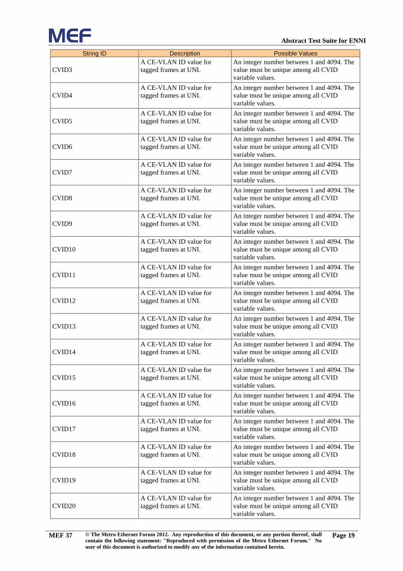
Abstract Test Suite for ENNI
MEF 37 © The Metro Ethernet Forum 2012. Any reproduction of this document, or any portion thereof, shall
contain the following statement: "Reproduced with permission of the Metro Ethernet Forum." No
user of this document is authorized to modify any of the information contained herein.
Page 19
String ID Description Possible Values
CVID3
A CE-VLAN ID value for
tagged frames at UNI.
An integer number between 1 and 4094. The
value must be unique among all CVID
variable values.
CVID4
A CE-VLAN ID value for
tagged frames at UNI.
An integer number between 1 and 4094. The
value must be unique among all CVID
variable values.
CVID5
A CE-VLAN ID value for
tagged frames at UNI.
An integer number between 1 and 4094. The
value must be unique among all CVID
variable values.
CVID6
A CE-VLAN ID value for
tagged frames at UNI.
An integer number between 1 and 4094. The
value must be unique among all CVID
variable values.
CVID7
A CE-VLAN ID value for
tagged frames at UNI.
An integer number between 1 and 4094. The
value must be unique among all CVID
variable values.
CVID8
A CE-VLAN ID value for
tagged frames at UNI.
An integer number between 1 and 4094. The
value must be unique among all CVID
variable values.
CVID9
A CE-VLAN ID value for
tagged frames at UNI.
An integer number between 1 and 4094. The
value must be unique among all CVID
variable values.
CVID10
A CE-VLAN ID value for
tagged frames at UNI.
An integer number between 1 and 4094. The
value must be unique among all CVID
variable values.
CVID11
A CE-VLAN ID value for
tagged frames at UNI.
An integer number between 1 and 4094. The
value must be unique among all CVID
variable values.
CVID12
A CE-VLAN ID value for
tagged frames at UNI.
An integer number between 1 and 4094. The
value must be unique among all CVID
variable values.
CVID13
A CE-VLAN ID value for
tagged frames at UNI.
An integer number between 1 and 4094. The
value must be unique among all CVID
variable values.
CVID14
A CE-VLAN ID value for
tagged frames at UNI.
An integer number between 1 and 4094. The
value must be unique among all CVID
variable values.
CVID15
A CE-VLAN ID value for
tagged frames at UNI.
An integer number between 1 and 4094. The
value must be unique among all CVID
variable values.
CVID16
A CE-VLAN ID value for
tagged frames at UNI.
An integer number between 1 and 4094. The
value must be unique among all CVID
variable values.
CVID17
A CE-VLAN ID value for
tagged frames at UNI.
An integer number between 1 and 4094. The
value must be unique among all CVID
variable values.
CVID18
A CE-VLAN ID value for
tagged frames at UNI.
An integer number between 1 and 4094. The
value must be unique among all CVID
variable values.
CVID19
A CE-VLAN ID value for
tagged frames at UNI.
An integer number between 1 and 4094. The
value must be unique among all CVID
variable values.
CVID20
A CE-VLAN ID value for
tagged frames at UNI.
An integer number between 1 and 4094. The
value must be unique among all CVID
variable values.

Abstract Test Suite for ENNI
MEF 37 © The Metro Ethernet Forum 2012. Any reproduction of this document, or any portion thereof, shall
contain the following statement: "Reproduced with permission of the Metro Ethernet Forum." No
user of this document is authorized to modify any of the information contained herein.
Page 20
String ID Description Possible Values
CVID21
A CE-VLAN ID value for
tagged frames at UNI.
An integer number between 1 and 4094. The
value must be unique among all CVID
variable values.
CVID22
A CE-VLAN ID value for
tagged frames at UNI.
An integer number between 1 and 4094. The
value must be unique among all CVID
variable values.
CVID23
A CE-VLAN ID value for
tagged frames at UNI.
An integer number between 1 and 4094. The
value must be unique among all CVID
variable values.
CVID24
A CE-VLAN ID value for
tagged frames at UNI.
An integer number between 1 and 4094. The
value must be unique among all CVID
variable values.
CVID25
A CE-VLAN ID value for
tagged frames at UNI.
An integer number between 1 and 4094. The
value must be unique among all CVID
variable values.
CVID26
A CE-VLAN ID value for
tagged frames at UNI.
An integer number between 1 and 4094. The
value must be unique among all CVID
variable values.
CVID27
A CE-VLAN ID value for
tagged frames at UNI.
An integer number between 1 and 4094. The
value must be unique among all CVID
variable values.
CVID28
A CE-VLAN ID value for
tagged frames at UNI.
An integer number between 1 and 4094. The
value must be unique among all CVID
variable values.
CVID29
A CE-VLAN ID value for
tagged frames at UNI.
An integer number between 1 and 4094. The
value must be unique among all CVID
variable values.
CVID30
A CE-VLAN ID value for
tagged frames at UNI.
An integer number between 1 and 4094. The
value must be unique among all CVID
variable values.
CVID31
A CE-VLAN ID value for
tagged frames at UNI.
An integer number between 1 and 4094. The
value must be unique among all CVID
variable values.
CVID32
A CE-VLAN ID value for
tagged frames at UNI.
An integer number between 1 and 4094. The
value must be unique among all CVID
variable values.
Multicast MAC Address A MAC multicast address used
for testing
Any valid MAC multicast address.
ENNI_Green_CoS1_IDs
A list of CoS ID identifiers
applied at ENNI.
S-Tag PCP values between 0 and 7 or S-Tag
PCP values between 0 and 7 and DEI set to 0.
The value must be disjoint with other ENNI
CoS IDs defined in this table.
ENNI_Yellow_CoS1_IDs
A list of CoS ID identifiers
applied at ENNI.
The variable is set either to
ENNI_Yellow_PCP_CoS1_IDs, if "S-Tag
PCP Color Indication" = "Yes" or to
ENNI_Yellow_DEI_CoS1_IDs, if "DEI
Color Indication" = "Yes". The value must be
disjoint with other ENNI CoS IDs defined in
this table.
ENNI_Yellow_PCP_CoS1_ID
s
A list of CoS ID identifiers
applied at ENNI.
S-Tag PCP values between 0 and 7. The
value must be disjoint with other ENNI CoS
IDs defined in this table.

Abstract Test Suite for ENNI
MEF 37 © The Metro Ethernet Forum 2012. Any reproduction of this document, or any portion thereof, shall
contain the following statement: "Reproduced with permission of the Metro Ethernet Forum." No
user of this document is authorized to modify any of the information contained herein.
Page 21
String ID Description Possible Values
ENNI_Yellow_DEI_CoS1_ID
s
A list of CoS ID identifiers
applied at ENNI.
S-Tag PCP values between 0 and 7 and DEI
is set to 1. S-Tag PCP value must be equal to
S-Tag PCP value of
ENNI_Green_CoS1_IDs.
ENNI_Residual_CoS_IDs
A list of CoS ID identifiers
applied at ENNI.
S-Tag PCP values between 0 and 7 and DEI
bit. ENNI_Residual_CoS_IDs must be
disjoint with other ENNI CoS IDs defined in
this table.
UNI_Green_CoS1_IDs
A list of CoS ID identifiers
applied at UNI.
C-Tag PCP values between 0 and 7 or DSCP
values between 0 and 63. The value must be
disjoint with other UNI CoS IDs defined in
this table.
UNI_Yellow_CoS1_IDs
A list of CoS ID identifiers
applied at UNI.
C-Tag PCP values between 0 and 7 or DSCP
values between 0 and 63. The value must be
disjoint with other UNI CoS IDs defined in
this table..
UNI_Residual_CoS_IDs
A list of CoS ID identifiers
applied at UNI.
C-Tag PCP values between 0 and 7 or DSCP
values between 0 and 63.
UNI_Residual_CoS_IDs must be disjoint
with other UNI CoS IDs defined in this table.
EI_Green_CoS1_IDs
A list of CoS ID identifiers
applied at an External Interface.
If the External Interface is UNI, the
EI_Green_CoS1_IDs is equal to
UNI_Green_CoS1_IDs, otherwise to
ENNI_Green_CoS1_IDs.
EI_Yellow_CoS1_IDs
A list of CoS ID identifiers
applied at an External Interface.
If the External Interface is UNI, the
EI_Yellow_CoS1_IDs is equal to UNI_
Yellow_CoS1_IDs, otherwise to ENNI_
Yellow_CoS1_IDs.
CIR1
Non-zero Committed
Information Rate applied in
bandwidth profiles.
Positive value, expressed in bits/s.
EIR1
Non-zero Excess Information
Rate applied in bandwidth
profiles.
Positive value, expressed in bits/s.
CIR2
Non-zero Committed
Information Rate applied in
bandwidth profiles.
Positive value, expressed in bits/s. CIR2 =
CIR/2 .
EIR2
Non-zero Excess Information
Rate applied in bandwidth
profiles.
Positive value, expressed in bits/s.
CBS1
Non-zero Committed Burst Size
applied in bandwidth profiles.
Positive value, expressed in bytes. The
recommended value for testing is at least
2*ENNI_MTU and can be different for a
given testing scenario
EBS1
Excess Burst Size applied in
bandwidth profiles.
Positive value, expressed in bytes. The
recommended value for testing is at least
2*ENNI_MTU and can be different for a
given testing scenario
BIR
Burst Information Rate Line Rate * FrameSize / (Frame Size + 20)
Rate in bits per second of frames transmitted,
back-to-back with minimum inter-frame gap.
BIR does not include the inter-frame gap,
preamble nor start of frame delimiter.

Abstract Test Suite for ENNI
MEF 37 © The Metro Ethernet Forum 2012. Any reproduction of this document, or any portion thereof, shall
contain the following statement: "Reproduced with permission of the Metro Ethernet Forum." No
user of this document is authorized to modify any of the information contained herein.
Page 22
5.4.3 ENNI configuration
The ENNI configuration used by the ATS is given in the tables below. The Table 9 specifies
the entire configuration of ENNI1, which is used in a different test topology as shown in
Figure 2, Figure 3, Figure 4 and Figure 5. The configuration of other ENNIs is specified only
for Service Attributes which configuration is different than for ENNI1. If an ENNI
configuration table does not specify a Service Attribute, the configuration of that Service
Attribute should be considered as specified for ENNI1.
The "Link OAM" capability is disabled on ENNI1 and ENNI2.
Table 9: ENNI1
Attribute Name Description Value
Operator ENNI Identifier An identifier for the ENNI intended for
management purposes
"ENNI1"
Physical Layer The physical layer of the links supporting
the ENNI
ENNI_PHY
Frame Format The format of the PDUs at the ENNI Frame formats as specified in Section
7.1.3 of [MEF 26]
Number of Links The number of physical links in the ENNI 1
Protection Mechanism The method for protection, if any, against
a failure
"none"
ENNI Maximum
Transmission Unit Size
The maximum length ENNI Frame in
bytes allowed at the ENNI
"ENNI_MTU"
End Point Map
The map that associates each ENNI S-Tag
Frame with an End Point
Test Topology1: ENNI1 End Point Map1;
Test Topology 2: ENNI1 End Point Map2;
Test Topology 3:ENNI1 End Point Map3
and ENNI1 End Point Map1;
Test Topology 4: ENNI1 End Point Map4
and ENNI1 End Point Map2;
Test Topology 5: ENNI1 End Point Map1
and ENNI1 End Point Map2 and ENNI1
End Point Map5;
Maximum Number of
OVCs
The maximum number of OVCs that the
Operator can support at the ENNI
OVC_Max_Number_ENNI
Maximum Number of
OVC End Points per
OVC
The maximum number of OVC End
Points that the Operator can support at the
ENNI for an OVC.
1
Table 10: ENNI2
Attribute Name Description Value
Operator ENNI Identifier An identifier for the ENNI intended for
management purposes
"ENNI2"
End Point Map
The map that associates each S-Tagged
ENNI Frame with an End Point
Test Topology 2: ENNI2 End Point Map1;
Test Topology 4: ENNI2 End Point Map2
Test Topology 5: ENNI2 End Point Map1
and ENNI2 End Point Map3

Abstract Test Suite for ENNI
MEF 37 © The Metro Ethernet Forum 2012. Any reproduction of this document, or any portion thereof, shall
contain the following statement: "Reproduced with permission of the Metro Ethernet Forum." No
user of this document is authorized to modify any of the information contained herein.
Page 23
Table 11: ENNI3
Attribute Name Description Value
Operator ENNI Identifier An identifier for the ENNI intended for
management purposes
"ENNI3"
ENNI Maximum
Transmission Unit Size
The maximum length ENNI Frame in
bytes allowed at the ENNI
1526
Protection Mechanism The method for protection, if any, against
a failure
"Link Aggregation"
Number of Links The number of physical links in the ENNI 2
End Point Map The map that associates each S-Tagged
ENNI Frame with an End Point
ENNI3 End Point Map1
Table 12: ENNI4
Attribute Name Description Value
Operator ENNI Identifier An identifier for the ENNI intended for
management purposes
"ENNI4"
End Point Map The map that associates each S-Tagged
ENNI Frame with an End Point
ENNI4 End Point Map1
The tables below provide the ENNI End Point maps used in the ENNI configuration tables
above.
ENNI1 End Point Map1 is used for Test Topology 1. It lists End Points on ENNI1 for point-
to-point OVCs or multipoint-to-multipoint OVCs with multiple Endpoints on ENNI1 and a
single End Point a UNI.
Table 13: ENNI1 End Point Map1
SVID ENNI End Point Type
SVID1 ENNI1_OVC1_End_Point_1 OVC End Point
SVID5 ENNI1_OVC3_End_Point_1Error!
Reference source not found.
OVC End Point
SVID6 ENNI1_OVC4_End_Point_1 OVC End Point
SVID18 ENNI1_OVC14_End_Point_1 OVC End Point
SVID21 ENNI1_OVC17_End_Point_1 OVC End Point
SVID23 ENNI1_OVC19_End_Point_1 OVC End Point
SVID25 ENNI1_OVC21_End_Point_1 OVC End Point
SVID27 ENNI1_OVC23_End_Point_1 OVC End Point
SVID28 ENNI1_OVC24_End_Point_1 OVC End Point
SVID30 ENNI1_OVC26_End_Point_1 OVC End Point
SVID34 ENNI1_OVC30_End_Point_1 OVC End Point
SVID36 ENNI1_OVC31_End_Point_1 OVC End Point
SVID37 ENNI1_OVC32_End_Point_1 OVC End Point
SVID44 ENNI1_OVC34_End_Point_1 OVC End Point
SVID45 ENNI1_OVC29_End_Point_1 OVC End Point
ENNI1 End Point Map2 is used for Test Topology 2. It lists End Points on ENNI1 for point-
to-point OVCs with a single End Point.on ENN1 and another ENNI.
Table 14: ENNI1 End Point Map2
SVID ENNI End Point Type
SVID2 ENNI1_OVC2_End_Point_1 OVC End Point

Abstract Test Suite for ENNI
MEF 37 © The Metro Ethernet Forum 2012. Any reproduction of this document, or any portion thereof, shall
contain the following statement: "Reproduced with permission of the Metro Ethernet Forum." No
user of this document is authorized to modify any of the information contained herein.
Page 24
SVID ENNI End Point Type
SVID9 ENNI1_OVC7_End_Point_1 OVC End Point
SVID32 ENNI1_OVC28_End_Point_1 OVC End Point
ENNI1 End Point Map3 is used for Test Topology 3. It lists End Points on ENNI1 for
multipoint-to-multipoint OVCs that associate ENNI1, and two UNIs.
Table 15: ENNI1 End Point Map3
SVID ENNI End Point Type
SVID7 ENNI1_OVC5_End_Point_1 OVC End Point
SVID8 ENNI1_OVC6_End_Point_1 OVC End Point
ENNI1 End Point Map4 is used for Test Topology 4. It lists End Points on ENNI1 for
multipoint-to-multipoint OVCs that associate ENNI1, and two other ENNIs.
Table 16: ENNI1 End Point Map4
SVID ENNI End Point Type
SVID11 ENNI1_OVC8_End_Point_1 OVC End Point
ENNI1 End Point Map5 is used for Test Topology 5. It lists End Points on ENNI1 for
multipoint-to-multipoint OVCs that associate ENNI1, another ENNI, and an UNI.
Table 17: ENNI1 End Point Map5
SVID ENNI End Point Type
SVID46 ENNI1_OVC35_End_Point_1 OVC End Point
SVID3 ENNI1_OVC36_End_Point_1 OVC End Point
ENNI2 End Point Map1 is used for Test Topology 2. It lists End points on ENNI2 for point-
to-point OVCs that associate ENNI2 and an other ENNI.
Table 18: ENNI2 End Point Map1
SVID ENNI End Point Type
SVID2 ENNI2_OVC2_End_Point_1 OVC End Point
SVID10 ENNI2_OVC7_End_Point_1 OVC End Point
SVID33 ENNI2_OVC28_End_Point_1 OVC End Point
ENNI2 End Point Map2 is used for Test Topology 4. It lists End Points on ENNI2 for
multipoint-to-multipoint OVCs that associate ENNI2, and two other ENNIs.
Table 19: ENNI2 End Point Map2
SVID ENNI End Point Type
SVID12 ENNI2_OVC8_End_Point_1 OVC End Point
ENNI2 End Point Map3 is used for Test Topology 5. It lists End Points on ENNI2 for
multipoint-to-multipoint OVCs that associate ENNI2, another ENNI and an UNI..
Table 20: ENNI2 End Point Map3
SVID ENNI End Point Type
SVID45 ENNI2_OVC35_End_Point_1 OVC End Point
SVID4 ENNI2_OVC36_End_Point_1 OVC End Point
ENNI3 End Point Map1 is used for Test Topology 1 (on ENNI3 the protection is enabled). It
lists End Points on ENNI3 for point-to-point OVCs that associate ENNI3 and UNI1.
Table 21: ENNI3 End Point Map1
SVID ENNI End Point Type
SVID17 ENNI3_OVC13_End_Point_1 OVC End Point
ENNI4 End Point Map1 is used for Test Topology 4. It lists End Points on ENNI4 for
multipoint-to-multipoint OVCs that associate ENNI4 and two other ENNIs.

Abstract Test Suite for ENNI
MEF 37 © The Metro Ethernet Forum 2012. Any reproduction of this document, or any portion thereof, shall
contain the following statement: "Reproduced with permission of the Metro Ethernet Forum." No
user of this document is authorized to modify any of the information contained herein.
Page 25
Table 22: ENNI4 End Point Map1
SVID ENNI End Point Type
SVID12 ENNI4_OVC8_End_Point_1 OVC End Point
5.4.4 OVC configuration
The OVC configuration used by the test suite is provided in the tables below. Table 23
specifies the entire configuration of OVC1. The configuration of other OVCs is specified
only for OVC Service Attributes whose configuration is different from the OVC1
configuration. If an OVC configuration table does not specify a Service Attribute, the
configuration of that Service Attribute should be considered as specified for OVC1.
Table 23: OVC1
Attribute Name Description Value
OVC Identifier A string that uniquely identifies the OVC. "OVC1"
OVC Type An indication of the number of OVC End
Points associated by the OVC.
"Point-to-Point"
OVC End Point List A list of OVC End Point Identifiers ["ENNI1_OVC1_End_Point_1",
"UNI1_OVC1_End_Point"]
Maximum Number of
UNI OVC End Points
The bound on the number of OVC End
Points at different UNIs that can be
associated by the OVC.
1
Maximum Number of
ENNI OVC End Points
The bound on the number of OVC End
Points at ENNIs that can be associated by
the OVC.
1
OVC Maximum
Transmission Unit Size
The maximum length in bytes allowed in a
frame mapped to an OVC End Point that
is associated by the OVC.
OVC_MTU
CE-VLAN ID
Preservation
A relationship between the format and
certain field values of the frame at one
External Interface and the format and
certain field values of the corresponding
frame at another External Interface that
allows the CE-VLAN ID value of the
Service Frame to be derived from the
ENNI Frame and vice versa.
"No"
CE-VLAN CoS
Preservation
A relationship between the format and
certain field values of the frame at one
External Interface and the format and
certain field values of the corresponding
frame at another External Interface that
allows the CE-VLAN CoS value of the
Service Frame to be derived from the
ENNI Frame and vice versa.
"No"
S-VLAN ID Preservation
A relationship between the S-VLAN ID of
a frame at one ENNI and the S-VLAN ID
of the corresponding frame at another
ENNI.
"No"
Color Forwarding The relationship between the Color of an
egress ENNI Frame and the Color of the
corresponding ingress ENNI Frame or
Service Frame.
"No"

Abstract Test Suite for ENNI
MEF 37 © The Metro Ethernet Forum 2012. Any reproduction of this document, or any portion thereof, shall
contain the following statement: "Reproduced with permission of the Metro Ethernet Forum." No
user of this document is authorized to modify any of the information contained herein.
Page 26
Attribute Name Description Value
Unicast Service Frame
Delivery
This attribute describes how ingress
frames mapped to an OVC End Point with
a unicast destination MAC address are
delivered to the other External Interfaces
with OVC End Points associated by the
OVC.
"Deliver Unconditionally"
Multicast Service Frame
Delivery
This attribute describes how ingress
frames mapped to an OVC End Point with
a multicast destination MAC address are
delivered to the other External Interfaces
with OVC End Points associated by the
OVC.
"Deliver Unconditionally"
Broadcast Service Frame
Delivery
This attribute describes how ingress
frames mapped to an OVC End Point with
the broadcast destination MAC address
are delivered to the other External
Interfaces with OVC End Points
associated by the OVC.
"Deliver Unconditionally"
Table 24: OVC2
Attribute Name Description Value
OVC Identifier A string that uniquely identifies the OVC. "OVC2"
Maximum Number of
UNI OVC End Points
The number of OVC End Points located at
different UNIs.
0
Maximum Number of
ENNI OVC End Points
The number of OVC End Points at
ENNIs.
2
OVC End Point List A list of OVC End Point Identifiers ["ENNI1_OVC2_End_Point_1",
"ENNI2_OVC2_End_Point_1"]
CE-VLAN ID
Preservation
A relationship between the format and
certain field values of the frame at one
External Interface and the format and
certain field values of the corresponding
frame at another External Interface that
allows the CE-VLAN ID value of the
Service Frame to be derived from the
ENNI Frame and vice versa.
"Yes"
CE-VLAN CoS
Preservation
A relationship between the format and
certain field values of the frame at one
External Interface and the format and
certain field values of the corresponding
frame at another External Interface that
allows the CE-VLAN CoS value of the
Service Frame to be derived from the
ENNI Frame and vice versa.
"Yes"
S-VLAN ID
Preservation
A relationship between the S-VLAN ID of
a frame at one ENNI and the S-VLAN ID
of the corresponding frame at another
ENNI.
"No"

Abstract Test Suite for ENNI
MEF 37 © The Metro Ethernet Forum 2012. Any reproduction of this document, or any portion thereof, shall
contain the following statement: "Reproduced with permission of the Metro Ethernet Forum." No
user of this document is authorized to modify any of the information contained herein.
Page 27
Table 25: OVC3
Attrihbute Name Description Value
OVC Identifier A string that uniquely identifies the OVC. "OVC3"
OVC End Point List A list of OVC End Point Identifiers [ENNI1_OVC3_End_Point_1,
UNI2_OVC3_End_Point]
Table 26: OVC4
Attribute Name Description Value
OVC Identifier A string that uniquely identifies the OVC. "OVC4"
OVC End Point List A list of OVC End Point Identifiers [ENNI1_OVC4_End_Point_1,
UNI5_OVC4_End_Point]
Table 27: OVC5
Attribute Name Description Value
OVC Identifier A string that uniquely identifies the OVC. "OVC5"
OVC Type An indication of the number of OVC End
Points associated by the OVC.
"Multipoint-to-Multipoint"
OVC End Point List A list of OVC End Point Identifiers
["ENNI1_OVC5_End_Point_1",
"UNI3_OVC5_End_Point",
"UNI4_OVC5_End_Point",]
Maximum Number of
UNI OVC End Points
The bound on the number of OVC End
Points at different UNIs that can be
associated by the OVC.
2
CE-VLAN ID
Preservation
A relationship between the format and
certain field values of the frame at one
External Interface and the format and
certain field values of the corresponding
frame at another External Interface that
allows the CE-VLAN ID value of the
Service Frame to be derived from the
ENNI Frame and vice versa.
"Yes"
CE-VLAN CoS
Preservation
A relationship between the format and
certain field values of the frame at one
External Interface and the format and
certain field values of the corresponding
frame at another External Interface that
allows the CE-VLAN CoS value of the
Service Frame to be derived from the
ENNI Frame and vice versa.
"Yes"
Table 28: OVC6
Attribute Name Description Value
OVC Identifier A string that uniquely identifies the OVC. "OVC6"
OVC Type An indication of the number of OVC End
Points associated by the OVC.
"Multipoint-to-Multipoint"
OVC End Point List A list of OVC End Point Identifiers
["ENNI1_OVC6_End_Point_1",
"UNI1_OVC6_End_Point",
"UNI2_OVC6_End_Point",]

Abstract Test Suite for ENNI
MEF 37 © The Metro Ethernet Forum 2012. Any reproduction of this document, or any portion thereof, shall
contain the following statement: "Reproduced with permission of the Metro Ethernet Forum." No
user of this document is authorized to modify any of the information contained herein.
Page 28
Attribute Name Description Value
Maximum Number of
UNI OVC End Points
The bound on the number of OVC End
Points at different UNIs that can be
associated by the OVC.
2
CE-VLAN ID
Preservation
A relationship between the format and
certain field values of the frame at one
External Interface and the format and
certain field values of the corresponding
frame at another External Interface that
allows the CE-VLAN ID value of the
Service Frame to be derived from the
ENNI Frame and vice versa.
"Yes"
Table 29: OVC7
Attribute Name Description Value
OVC Identifier A string that uniquely identifies the OVC. "OVC7"
Maximum Number of
UNI OVC End Points
The number of OVC End Points located at
different UNIs.
0
Maximum Number of
ENNI OVC End Points
The number of OVC End Points at
ENNIs.
2
OVC End Point List A list of OVC End Point Identifiers ["ENNI1_OVC7_End_Point_1",
"ENNI2_OVC7_End_Point_1"]
S-VLAN ID
Preservation
A relationship between the S-VLAN ID of
a frame at one ENNI and the S-VLAN ID
of the corresponding frame at another
ENNI.
"No"
Table 30: OVC8
Attribute Name Description Value
OVC Identifier A string that uniquely identifies the OVC. "OVC8"
OVC Type An indication of the number of OVC End
Points associated by the OVC
“Multipoint-to-Multipoint”
Maximum Number of
UNI OVC End Points
The number of OVC End Points located at
different UNIs.
0
Maximum Number of
ENNI OVC End Points
The number of OVC End Points at
ENNIs.
3
OVC End Point List A list of OVC End Point Identifiers
["ENNI1_OVC8_End_Point_1",
"ENNI2_OVC8_End_Point_1",
"ENNI4_OVC8_End_Point_1"]
Note: The " Unicast Frame Delivery", " Multicast Frame Delivery", and " Broadcast Frame
Delivery " Service Attributes for OVC9 must be set to "Deliver Conditionally".
The ATS assumes that "Conditional Unicast Frame Delivery" is realized via MAC Address
Learning, so the Operator MEN should support "MAC Address Learning" capability.
The ATS assumes that "Conditional Multicast Frame Delivery" and "Conditional Broadcast
Frame Delivery" are realized via filtering of specific MAC addresses, so the Operator MEN
should support "Frame Forwarding to Specific EI" capability. In case of OVC9 the ATS
assumes that broadcast frames and multicast frames with the destination MAC address
"Multicast MAC Address" are blocked towards ENNI2.

Abstract Test Suite for ENNI
MEF 37 © The Metro Ethernet Forum 2012. Any reproduction of this document, or any portion thereof, shall
contain the following statement: "Reproduced with permission of the Metro Ethernet Forum." No
user of this document is authorized to modify any of the information contained herein.
Page 29
Table 31: OVC10
Attribute Name Description Value
OVC Identifier A string that uniquely identifies the OVC. "OVC10"
OVC End Point List A list of OVC End Point Identifiers ["ENNI1_OVC10_End_Point_1",
"UNI1_OVC10_End_Point"]
Table 32: OVC11
Attribute Name Description Value
OVC Identifier A string that uniquely identifies the OVC. "OVC11"
OVC End Point List A list of OVC End Point Identifiers [ENNI1_OVC11_End_Point_1,
UNI1_OVC11_End_Point]
Table 33: OVC12
Attribute Name Description Value
OVC Identifier A string that uniquely identifies the OVC. "OVC12"
OVC End Point List A list of OVC End Point Identifiers ["ENNI1_OVC12_End_Point_1",
"UNI1_OVC12_End_Point"]
Table 34: OVC13
Attribute Name Description Value
OVC Identifier A string that uniquely identifies the OVC. "OVC13"
OVC End Point List A list of OVC End Point Identifiers ["ENNI3_OVC13_End_Point_1",
"UNI1_OVC13_End_Point"]
Table 35: OVC14
Attribute Name Description Value
OVC Identifier A string that uniquely identifies the OVC. "OVC14"
OVC End Point List A list of OVC End Point Identifiers ["ENNI1_OVC14_End_Point_1"],
"UNI1_OVC14_End_Point"]
Table 36: OVC17
Attribute Name Description Value
OVC Identifier A string that uniquely identifies the OVC. "OVC17"
OVC End Point List A list of OVC End Point Identifiers ["ENNI1_OVC17_End_Point_1"],
"UNI1_OVC17_End_Point"]
Table 37: OVC19
Attribute Name Description Value
OVC Identifier A string that uniquely identifies the OVC. "OVC19"
OVC End Point List A list of OVC End Point Identifiers ["ENNI1_OVC19_End_Point_1"],
"UNI1_OVC19_End_Point"]

Abstract Test Suite for ENNI
MEF 37 © The Metro Ethernet Forum 2012. Any reproduction of this document, or any portion thereof, shall
contain the following statement: "Reproduced with permission of the Metro Ethernet Forum." No
user of this document is authorized to modify any of the information contained herein.
Page 30
Table 38: OVC21
Attribute Name Description Value
OVC Identifier A string that uniquely identifies the OVC. "OVC21"
OVC End Point List A list of OVC End Point Identifiers ["ENNI1_OVC21_End_Point_1"],
"UNI1_OVC21_End_Point"]
Table 39: OVC23
Attribute Name Description Value
OVC Identifier A string that uniquely identifies the OVC. "OVC23"
OVC End Point List A list of OVC End Point Identifiers ["ENNI1_OVC23_End_Point_1"],
"UNI1_OVC23_End_Point"]
Table 40: OVC24
Attribute Name Description Value
OVC Identifier A string that uniquely identifies the OVC. "OVC24"
OVC End Point List A list of OVC End Point Identifiers ["ENNI1_OVC24_End_Point_1"],
"UNI1_OVC24_End_Point"]
Table 41: OVC26
Attribute Name Description Value
OVC Identifier A string that uniquely identifies the OVC. "OVC26"
OVC End Point List A list of OVC End Point Identifiers ["ENNI1_OVC26_End_Point_1"],
"UNI1_OVC26_End_Point"]
Color Forwarding The relationship between the Color of an
egress ENNI Frame and the Color of the
corresponding ingress ENNI Frame or
Service Frame.
"Yes"
Table 42: OVC28
Attribute Name Description Value
OVC Identifier A string that uniquely identifies the OVC. "OVC28"
Maximum Number of
UNI OVC End Points
The number of OVC End Points located at
different UNIs.
0
Maximum Number of
ENNI OVC End Points
The number of OVC End Points at
ENNIs.
2
OVC End Point List A list of OVC End Point Identifiers ["ENNI1_OVC28_End_Point_1"],
"ENNI2_OVC28_End_Point_1"]
Color Forwarding The relationship between the Color of an
egress ENNI Frame and the Color of the
corresponding ingress ENNI Frame or
Service Frame.
"Yes"
Table 43: OVC29
Attribute Name Description Value
OVC Identifier A string that uniquely identifies the OVC. "OVC29"
OVC End Point List A list of OVC End Point Identifiers ["ENNI1_OVC29_End_Point_1",
"UNI1_OVC29_End_Point"]
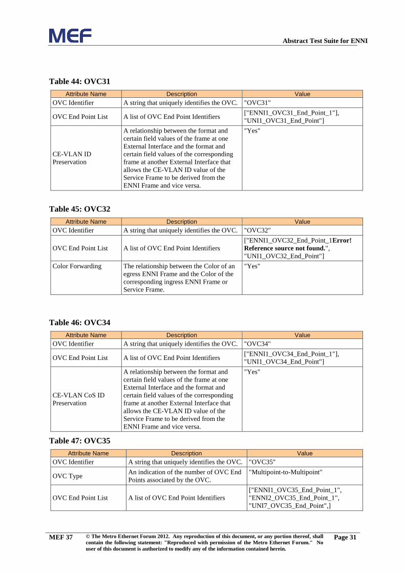
Abstract Test Suite for ENNI
MEF 37 © The Metro Ethernet Forum 2012. Any reproduction of this document, or any portion thereof, shall
contain the following statement: "Reproduced with permission of the Metro Ethernet Forum." No
user of this document is authorized to modify any of the information contained herein.
Page 31
Table 44: OVC31
Attribute Name Description Value
OVC Identifier A string that uniquely identifies the OVC. "OVC31"
OVC End Point List A list of OVC End Point Identifiers ["ENNI1_OVC31_End_Point_1"],
"UNI1_OVC31_End_Point"]
CE-VLAN ID
Preservation
A relationship between the format and
certain field values of the frame at one
External Interface and the format and
certain field values of the corresponding
frame at another External Interface that
allows the CE-VLAN ID value of the
Service Frame to be derived from the
ENNI Frame and vice versa.
"Yes"
Table 45: OVC32
Attribute Name Description Value
OVC Identifier A string that uniquely identifies the OVC. "OVC32"
OVC End Point List A list of OVC End Point Identifiers
["ENNI1_OVC32_End_Point_1Error!
Reference source not found.",
"UNI1_OVC32_End_Point"]
Color Forwarding The relationship between the Color of an
egress ENNI Frame and the Color of the
corresponding ingress ENNI Frame or
Service Frame.
"Yes"
Table 46: OVC34
Attribute Name Description Value
OVC Identifier A string that uniquely identifies the OVC. "OVC34"
OVC End Point List A list of OVC End Point Identifiers ["ENNI1_OVC34_End_Point_1"],
"UNI1_OVC34_End_Point"]
CE-VLAN CoS ID
Preservation
A relationship between the format and
certain field values of the frame at one
External Interface and the format and
certain field values of the corresponding
frame at another External Interface that
allows the CE-VLAN ID value of the
Service Frame to be derived from the
ENNI Frame and vice versa.
"Yes"
Table 47: OVC35
Attribute Name Description Value
OVC Identifier A string that uniquely identifies the OVC. "OVC35"
OVC Type An indication of the number of OVC End
Points associated by the OVC.
"Multipoint-to-Multipoint"
OVC End Point List A list of OVC End Point Identifiers
["ENNI1_OVC35_End_Point_1",
"ENNI2_OVC35_End_Point_1",
"UNI7_OVC35_End_Point",]
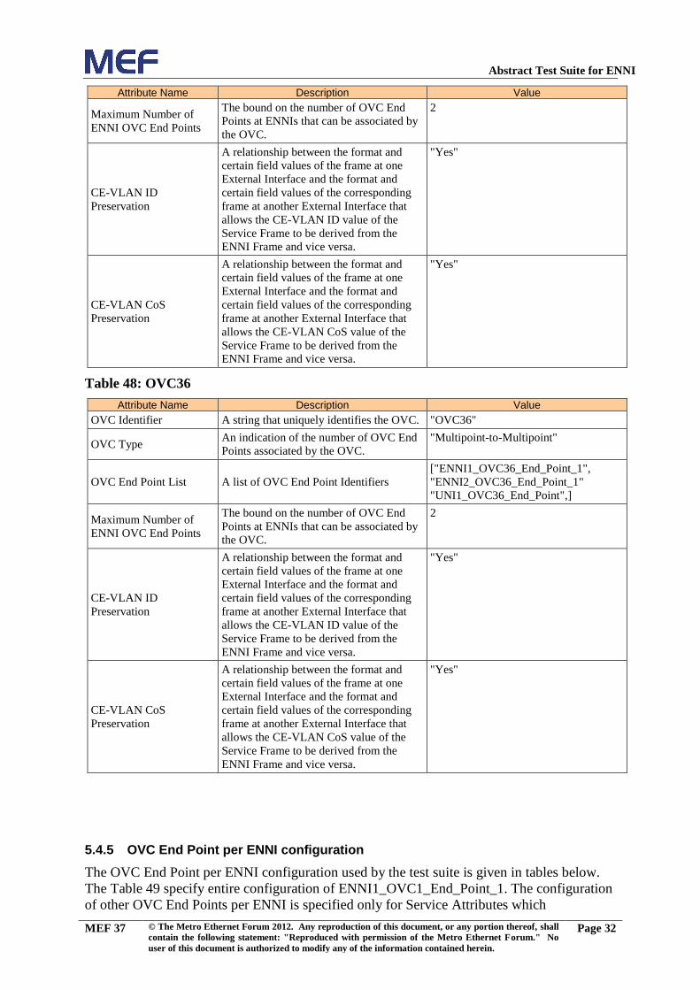
Abstract Test Suite for ENNI
MEF 37 © The Metro Ethernet Forum 2012. Any reproduction of this document, or any portion thereof, shall
contain the following statement: "Reproduced with permission of the Metro Ethernet Forum." No
user of this document is authorized to modify any of the information contained herein.
Page 32
Attribute Name Description Value
Maximum Number of
ENNI OVC End Points
The bound on the number of OVC End
Points at ENNIs that can be associated by
the OVC.
2
CE-VLAN ID
Preservation
A relationship between the format and
certain field values of the frame at one
External Interface and the format and
certain field values of the corresponding
frame at another External Interface that
allows the CE-VLAN ID value of the
Service Frame to be derived from the
ENNI Frame and vice versa.
"Yes"
CE-VLAN CoS
Preservation
A relationship between the format and
certain field values of the frame at one
External Interface and the format and
certain field values of the corresponding
frame at another External Interface that
allows the CE-VLAN CoS value of the
Service Frame to be derived from the
ENNI Frame and vice versa.
"Yes"
Table 48: OVC36
Attribute Name Description Value
OVC Identifier A string that uniquely identifies the OVC. "OVC36"
OVC Type An indication of the number of OVC End
Points associated by the OVC.
"Multipoint-to-Multipoint"
OVC End Point List A list of OVC End Point Identifiers
["ENNI1_OVC36_End_Point_1",
"ENNI2_OVC36_End_Point_1"
"UNI1_OVC36_End_Point",]
Maximum Number of
ENNI OVC End Points
The bound on the number of OVC End
Points at ENNIs that can be associated by
the OVC.
2
CE-VLAN ID
Preservation
A relationship between the format and
certain field values of the frame at one
External Interface and the format and
certain field values of the corresponding
frame at another External Interface that
allows the CE-VLAN ID value of the
Service Frame to be derived from the
ENNI Frame and vice versa.
"Yes"
CE-VLAN CoS
Preservation
A relationship between the format and
certain field values of the frame at one
External Interface and the format and
certain field values of the corresponding
frame at another External Interface that
allows the CE-VLAN CoS value of the
Service Frame to be derived from the
ENNI Frame and vice versa.
"Yes"
5.4.5 OVC End Point per ENNI configuration
The OVC End Point per ENNI configuration used by the test suite is given in tables below.
The Table 49 specify entire configuration of ENNI1_OVC1_End_Point_1. The configuration
of other OVC End Points per ENNI is specified only for Service Attributes which

Abstract Test Suite for ENNI
MEF 37 © The Metro Ethernet Forum 2012. Any reproduction of this document, or any portion thereof, shall
contain the following statement: "Reproduced with permission of the Metro Ethernet Forum." No
user of this document is authorized to modify any of the information contained herein.
Page 33
configuration is different than for ENNI1_OVC1_End_Point_1. If a configuration table does
not specify a Service Attribute, the configuration of that Service Attribute should be
considered as specified for ENNI1_OVC1_End_Point_1.
Table 49: ENNI1_OVC1_End_Point_1
Attribute Name Description Value
OVC End Point Identifier An identifier for the OVC End Point,
which is unique across the Operator MEN
"ENNI1_OVC1_End_Point_1"
Class of Service
Identifiers
The way that a Class of Service is
determined for ENNI Frames.
[<"BestEffort", "OVC", [all]>,]
Ingress Bandwidth Profile
Per OVC End Point
Ingress policing by the Operator MEN on
all ingress ENNI Frames mapped to the
OVC End Point. The attribute specifies
mapping between Bandwidth Profile
instances and CoS Labels. The mapping is
one-to-one mapping.
"No"
Ingress Bandwidth Profile
Per ENNI Class of
Service Identifier
Ingress policing by the Operator MEN on
all ingress ENNI Frames with the Class of
Service Identifier for the receiving
Operator MEN. The attribute specifies
mapping between Bandwidth Profile
instances and CoS Labels. The mapping is
one-to-one mapping.
"No"
Egress Bandwidth Profile
Per End Point
Egress policing by the Operator MEN on
all egress ENNI Frames mapped to the
OVC End Point. The attribute specifies
mapping between Bandwidth Profile
instances and CoS Labels. The mapping is
one-to-one mapping.
"No"
Egress Bandwidth Profile
Per ENNI Class of
Service Identifier
Egress policing by the Operator MEN on
all egress ENNI Frames with the Class of
Service Identifier for the receiving MEN.
The attribute specifies mapping between
Bandwidth Profile instances and CoS
Labels. The mapping is one-to-one
mapping.
"No"
Table 50: ENNI1_OVC2_End_Point_1
Attribute Name Description Value
OVC End Point Identifier
An identifier for the OVC End Point,
which is unique across the Operator MEN
"ENNI1_OVC2_End_Point_1"
Table 51: ENNI2_OVC2_End_Point_1
Attribute Name Description Value
OVC End Point Identifier
An identifier for the OVC End Point,
which is unique across the Operator MEN
"ENNI2_OVC2_End_Point_1"

Abstract Test Suite for ENNI
MEF 37 © The Metro Ethernet Forum 2012. Any reproduction of this document, or any portion thereof, shall
contain the following statement: "Reproduced with permission of the Metro Ethernet Forum." No
user of this document is authorized to modify any of the information contained herein.
Page 34
Table 52: ENNI1_OVC3_End_Point_1
Attribute Name Description Value
OVC End Point Identifier An identifier for the OVC End Point,
which is unique across the Operator MEN
"ENNI1_OVC3_End_Point_1"
Class of Service
Identifiers
The way that a Class of Service is
determined for ENNI Frames.
[
< "BestEffort", "PCP", [0]>,
< "Discard", "PCP", [1,2,3,4,5,6,7]>,
]
Ingress Bandwidth Profile
Per OVC End Point
Ingress policing by the Operator MEN on
all ingress ENNI Frames mapped to the
OVC End Point. The attribute specifies
mapping between Bandwidth Profile
instances and CoS Labels. The mapping is
one-to-one mapping.
[<CIR1,CBS1,0,0,0,1>, "BestEffort">
]
Table 53: ENNI1_OVC4_End_Point_1
Attribute Name Description Value
OVC End Point Identifier An identifier for the OVC End Point,
which is unique across the Operator MEN
"ENNI1_OVC4_End_Point_1"
Class of Service
Identifiers
The way that a Class of Service is
determined for ENNI Frames.
[
<"BestEffort", "PCP", [0]>,
<"Discard", "PCP", [1,2,3,4,5,6,7]>,
]
Ingress Bandwidth Profile
Per OVC End Point
Ingress policing by the Operator MEN on
all ingress ENNI Frames mapped to the
OVC End Point. The attribute specifies
mapping between Bandwidth Profile
instances and CoS Labels. The mapping is
one-to-one mapping.
[<<CIR1,CBS1,0,0,0,1>, "BestEffort">,
<<0,0,0,0,0,1>, "Discard">,
]
Table 54: ENNI1_OVC5_End_Point_1
Attribute Name Description Value
OVC End Point Identifier
An identifier for the OVC End Point,
which is unique across the Operator MEN
"ENNI1_OVC5_End_Point_1"
Table 55: ENNI1_OVC6_End_Point_1
Attribute Name Description Value
OVC End Point Identifier An identifier for the OVC End Point,
which is unique across the Operator MEN
"ENNI1_OVC6_End_Point_1"
Table 56: ENNI1_OVC7_End_Point_1
Attribute Name Description Value
OVC End Point Identifier
An identifier for the OVC End Point,
which is unique across the Operator MEN
"ENNI1_OVC7_End_Point_1"

Abstract Test Suite for ENNI
MEF 37 © The Metro Ethernet Forum 2012. Any reproduction of this document, or any portion thereof, shall
contain the following statement: "Reproduced with permission of the Metro Ethernet Forum." No
user of this document is authorized to modify any of the information contained herein.
Page 35
Table 57: ENNI2_OVC7_End_Point_1
Attribute Name Description Value
OVC End Point Identifier
An identifier for the OVC End Point,
which is unique across the Operator MEN
"ENNI2_OVC7_End_Point_1"
Table 58: ENNI1_OVC8_End_Point_1
Attribute Name Description Value
OVC End Point Identifier
An identifier for the OVC End Point,
which is unique across the Operator MEN
"ENNI1_OVC8_End_Point_1"
Table 59: ENNI2_OVC8_End_Point_1
Attribute Name Description Value
OVC End Point Identifier
An identifier for the OVC End Point,
which is unique across the Operator MEN
"ENNI2_OVC8_End_Point_1"
Table 60: ENNI4_OVC8_End_Point_1
Attribute Name Description Value
OVC End Point Identifier
An identifier for the OVC End Point,
which is unique across the Operator MEN
"ENNI4_OVC8_End_Point_1"
Table 61: ENNI2_OVC9_End_Point_1
Attribute Name Description Value
OVC End Point Identifier
An identifier for the OVC End Point,
which is unique across the Operator MEN
"ENNI2_OVC9_End_Point_1"
Table 62: ENNI4_OVC9_End_Point_1
Attribute Name Description Value
OVC End Point Identifier
An identifier for the OVC End Point,
which is unique across the Operator MEN
"ENNI4_OVC9_End_Point_1"
Table 63: ENNI1_OVC10_End_Point_1
Attribute Name Description Value
OVC End Point Identifier An identifier for the OVC End Point,
which is unique across the Operator MEN
"ENNI1_OVC10_End_Point_1"
Table 64: ENNI1_OVC11_End_Point_1
Attribute Name Description Value
OVC End Point Identifier An identifier for the OVC End Point,
which is unique across the Operator MEN
"ENNI1_OVC11_End_Point_1"
Class of Service
Identifiers
The way that a Class of Service is
determined for ENNI Frames.
[
< "BestEffort", [0]>,
< "Discard", [1,2,3,4,5,6,7]>,
]

Abstract Test Suite for ENNI
MEF 37 © The Metro Ethernet Forum 2012. Any reproduction of this document, or any portion thereof, shall
contain the following statement: "Reproduced with permission of the Metro Ethernet Forum." No
user of this document is authorized to modify any of the information contained herein.
Page 36
Attribute Name Description Value
Ingress Bandwidth Profile
Per OVC End Point
Ingress policing by the Operator MEN on
all ingress ENNI Frames mapped to the
OVC End Point. The attribute specifies
mapping between Bandwidth Profile
instances and CoS Labels. The mapping is
one-to-one mapping.
[<<CIR1,CBS1,0,0,0,1>, "BestEffort">
]
Table 65: ENNI1_OVC12_End_Point_1
Attribute Name Description Value
OVC End Point Identifier An identifier for the OVC End Point,
which is unique across the Operator MEN
"ENNI1_OVC12_End_Point_1"
Class of Service
Identifiers
The way that a Class of Service is
determined for ENNI Frames.
[
<"BestEffort", "PCP", [0]>,
<"Discard", "PCP", [1,2,3,4,5,6,7]>,
]
Ingress Bandwidth Profile
Per OVC End Point
Ingress policing by the Operator MEN on
all ingress ENNI Frames mapped to the
OVC End Point. The attribute specifies
mapping between Bandwidth Profile
instances and CoS Labels. The mapping is
one-to-one mapping.
[<<CIR1,CBS1,0,0,0,1>, "BestEffort">,
<<0,0,0,0,0,1>, "Discard">,
]
Table 66: ENNI3_OVC13_End_Point_1
Attribute Name Description Value
OVC End Point Identifier An identifier for the OVC End Point,
which is unique across the Operator MEN
"ENNI3_OVC13_End_Point_1"
Table 67: ENNI1_OVC14_End_Point_1
Attribute Name Description Value
OVC End Point Identifier An identifier for the OVC End Point,
which is unique across the Operator MEN
"ENNI1_OVC14_End_Point_1"
Class of Service
Identifiers
The way that a Class of Service is
determined for an ENNI Frame at each
ENNI.
[ ENNI_Yellow_CoS1_IDs,
ENNI_Green_CoS1_IDs,
ENNI_Residual_CoS_IDs]
Ingress Bandwidth Profile
Per Class of Service
Ingress policing by the Operator MEN on
all ingress ENNI Frames mapped to the
OVC End Point that have the given ENNI
Class of Service Identifier. The attribute
specifies mapping between Bandwidth
Profile instances and CoS Labels. The
mapping is one-to-one mapping.
CoS1:< CIR1,CBS1,0,0,0,1>
CoS2:<0,0,0,0,0,1>
Egress Bandwidth Profile
Per ENNI Class of
Service Identifier
Egress policing by the Operator MEN on
all egress ENNI Frames with the Class of
Service Identifier for the receiving MEN.
The attribute specifies mapping between
Bandwidth Profile instances and CoS
Labels. The mapping is one-to-one
mapping.
CoS1:< CIR1,CBS1,0,0,0,1>
CoS2:<0,0,0,0,0,1>

Abstract Test Suite for ENNI
MEF 37 © The Metro Ethernet Forum 2012. Any reproduction of this document, or any portion thereof, shall
contain the following statement: "Reproduced with permission of the Metro Ethernet Forum." No
user of this document is authorized to modify any of the information contained herein.
Page 37
Class of Service
Identifiers
The way that a Class of Service is
determined for an ENNI Frame at each
ENNI.
[ ENNI_Yellow_CoS1_IDs,
ENNI_Green_CoS1_IDs,
ENNI_Residual_CoS_IDs]
Ingress Bandwidth Profile
Per Class of Service
Ingress policing by the Operator MEN on
all ingress ENNI Frames mapped to the
OVC End Point that have the given ENNI
Class of Service Identifier. The attribute
specifies mapping between Bandwidth
Profile instances and CoS Labels. The
mapping is one-to-one mapping.
CoS1:< CIR1,CBS1,0,0,1,1>
CoS2:<0,0,0,0,1,1>
Egress Bandwidth Profile
Per ENNI Class of
Service Identifier
Egress policing by the Operator MEN on
all egress ENNI Frames with the Class of
Service Identifier for the receiving MEN.
The attribute specifies mapping between
Bandwidth Profile instances and CoS
Labels. The mapping is one-to-one
mapping.
CoS1:< CIR1,CBS1,0,0,1,1>
CoS2:<0,0,0,0,1,1>
Table 68: ENNI1_OVC17_End_Point_1
Attribute Name Description Value
OVC End Point Identifier An identifier for the OVC End Point,
which is unique across the Operator MEN
"ENNI1_OVC17_End_Point_1"
Class of Service
Identifiers
The way that a Class of Service is
determined for an ENNI Frame at each
ENNI.
[ ENNI_Yellow_CoS1_IDs,
ENNI_Green_CoS1_IDs,
ENNI_Residual_CoS_IDs]
Ingress Bandwidth Profile
Per Class of Service
Ingress policing by the Operator MEN on
all ingress ENNI Frames mapped to the
OVC End Point that have the given ENNI
Class of Service Identifier. The attribute
specifies mapping between Bandwidth
Profile instances and CoS Labels. The
mapping is one-to-one mapping.
CoS1:<0,0,EIR1,EBS1,0,1>
CoS2:<0,0,0,0,0,1>
Egress Bandwidth Profile
Per ENNI Class of
Service Identifier
Egress policing by the Operator MEN on
all egress ENNI Frames with the Class of
Service Identifier for the receiving MEN.
The attribute specifies mapping between
Bandwidth Profile instances and CoS
Labels. The mapping is one-to-one
mapping.
CoS1:<0,0, EIR1,EBS1,0,1>
CoS2:<0,0,0,0,0,1>

Abstract Test Suite for ENNI
MEF 37 © The Metro Ethernet Forum 2012. Any reproduction of this document, or any portion thereof, shall
contain the following statement: "Reproduced with permission of the Metro Ethernet Forum." No
user of this document is authorized to modify any of the information contained herein.
Page 38
Table 69: ENNI1_OVC19_End_Point_1
Attribute Name Description Value
OVC End Point Identifier An identifier for the OVC End Point,
which is unique across the Operator MEN
"ENNI1_OVC19_End_Point_1"
Ingress Bandwidth Profile
Per ENNI Class of
Service Identifier
Ingress policing by the Operator MEN on
all ingress ENNI Frames with the Class of
Service Identifier for the receiving
Operator MEN. The attribute specifies
mapping between Bandwidth Profile
instances and CoS Labels. The mapping is
one-to-one mapping.
"Yes"
Class of Service
Identifiers
The way that a Class of Service is
determined for an ENNI Frame at each
ENNI.
[ ENNI_Yellow_CoS1_IDs,
ENNI_Green_CoS1_IDs,
ENNI_Residual_CoS_IDs]
Ingress Bandwidth Profile
Per Class of Service
Ingress policing by the Operator MEN on
all ingress ENNI Frames mapped to the
OVC End Point that have the given ENNI
Class of Service Identifier. The attribute
specifies mapping between Bandwidth
Profile instances and CoS Labels. The
mapping is one-to-one mapping.
CoS1:< CIR1,CBS1, EIR1,EBS1,0,1>
CoS2:<0,0,0,0,0,1>
Egress Bandwidth Profile
Per ENNI Class of
Service Identifier
Egress policing by the Operator MEN on
all egress ENNI Frames with the Class of
Service Identifier for the receiving MEN.
The attribute specifies mapping between
Bandwidth Profile instances and CoS
Labels. The mapping is one-to-one
mapping.
CoS1:< CIR1,CBS1, EIR1,EBS1,0,1>
CoS2:<0,0,0,0,0,1>
Table 70: ENNI1_OVC21_End_Point_1
Attribute Name Description Value
OVC End Point Identifier
An identifier for the OVC End Point,
which is unique across the Operator MEN
"ENNI1_OVC21_End_Point_1"

Abstract Test Suite for ENNI
MEF 37 © The Metro Ethernet Forum 2012. Any reproduction of this document, or any portion thereof, shall
contain the following statement: "Reproduced with permission of the Metro Ethernet Forum." No
user of this document is authorized to modify any of the information contained herein.
Page 39
Table 71: ENNI1_OVC23_End_Point_1
Attribute Name Description Value
OVC End Point Identifier
An identifier for the OVC End Point,
which is unique across the Operator MEN
"ENNI1_OVC23_End_Point_1"
Table 72: ENNI1_OVC24_End_Point_1
Attribute Name Description Value
OVC End Point Identifier
An identifier for the OVC End Point,
which is unique across the Operator MEN
"ENNI1_OVC24_End_Point_1"
Table 73: ENNI1_OVC26_End_Point_1
Attribute Name Description Value
OVC End Point Identifier
An identifier for the OVC End Point,
which is unique across the Operator MEN
"ENNI1_OVC26_End_Point_1"
Ingress Bandwidth Profile
Per Class of Service
Ingress policing by the Operator MEN on
all ingress ENNI Frames mapped to the
OVC End Point that have the given ENNI
Class of Service Identifier. The attribute
specifies mapping between Bandwidth
Profile instances and CoS Labels. The
mapping is one-to-one mapping.
CoS1:< CIR1, CBS1, EIR1, EBS1,1,1>
CoS2:<0,0,0,0,1,1>
Egress Bandwidth Profile
Per ENNI Class of
Service Identifier
Egress policing by the Operator MEN on
all egress ENNI Frames with the Class of
Service Identifier for the receiving MEN.
The attribute specifies mapping between
Bandwidth Profile instances and CoS
Labels. The mapping is one-to-one
mapping.
CoS1:< CIR1, CBS1, EIR1, EBS1,1,1>
CoS2:<0,0,0,0,1,1>

Abstract Test Suite for ENNI
MEF 37 © The Metro Ethernet Forum 2012. Any reproduction of this document, or any portion thereof, shall
contain the following statement: "Reproduced with permission of the Metro Ethernet Forum." No
user of this document is authorized to modify any of the information contained herein.
Page 40
Table 74: ENNI1_OVC28_End_Point_1
Attribute Name Description Value
OVC End Point Identifier An identifier for the OVC End Point,
which is unique across the Operator MEN
"ENNI1_OVC28_End_Point_1"
Ingress Bandwidth Profile
Per ENNI Class of
Service Identifier
Ingress policing by the Operator MEN on
all ingress ENNI Frames with the Class of
Service Identifier for the receiving
Operator MEN. The attribute specifies
mapping between Bandwidth Profile
instances and CoS Labels. The mapping is
one-to-one mapping.
"Yes"
Class of Service
Identifiers
The way that a Class of Service is
determined for an ENNI Frame at each
ENNI.
[ ENNI_Yellow_CoS1_IDs,
ENNI_Green_CoS1_IDs,
ENNI_Residual_CoS_IDs]
Ingress Bandwidth Profile
Per Class of Service
Ingress policing by the Operator MEN on
all ingress ENNI Frames mapped to the
OVC End Point that have the given ENNI
Class of Service Identifier. The attribute
specifies mapping between Bandwidth
Profile instances and CoS Labels. The
mapping is one-to-one mapping.
CoS1:< CIR1, CBS1, EIR1, EBS1,0,1>
CoS2:<0,0,0,0,0,1>
Egress Bandwidth Profile
Per ENNI Class of
Service Identifier
Egress policing by the Operator MEN on
all egress ENNI Frames with the Class of
Service Identifier for the receiving MEN.
The attribute specifies mapping between
Bandwidth Profile instances and CoS
Labels. The mapping is one-to-one
mapping.
CoS1:< CIR1, CBS1, EIR1, EBS1,0,1>
CoS2:<0,0,0,0,0,1>
Table 75: ENNI2_OVC28_End_Point_1
Attribute Name Description Value
OVC End Point Identifier An identifier for the OVC End Point,
which is unique across the Operator MEN
"ENNI2_OVC28_End_Point_1"
Ingress Bandwidth Profile
Per ENNI Class of
Service Identifier
Ingress policing by the Operator MEN on
all ingress ENNI Frames with the Class of
Service Identifier for the receiving
Operator MEN. The attribute specifies
mapping between Bandwidth Profile
instances and CoS Labels. The mapping is
one-to-one mapping.
"Yes"
Class of Service
Identifiers
The way that a Class of Service is
determined for an ENNI Frame at each
ENNI.
[ ENNI_Yellow_CoS1_IDs,
ENNI_Green_CoS1_IDs,
ENNI_Residual_CoS_IDs]
Ingress Bandwidth Profile
Per Class of Service
Ingress policing by the Operator MEN on
all ingress ENNI Frames mapped to the
OVC End Point that have the given ENNI
Class of Service Identifier. The attribute
specifies mapping between Bandwidth
Profile instances and CoS Labels. The
mapping is one-to-one mapping.
CoS1:< CIR1, CBS1, EIR1, EBS1,0,1>
CoS2:<0,0,0,0,0,1>

Abstract Test Suite for ENNI
MEF 37 © The Metro Ethernet Forum 2012. Any reproduction of this document, or any portion thereof, shall
contain the following statement: "Reproduced with permission of the Metro Ethernet Forum." No
user of this document is authorized to modify any of the information contained herein.
Page 41
Attribute Name Description Value
Egress Bandwidth Profile
Per ENNI Class of
Service Identifier
Egress policing by the Operator MEN on
all egress ENNI Frames with the Class of
Service Identifier for the receiving MEN.
The attribute specifies mapping between
Bandwidth Profile instances and CoS
Labels. The mapping is one-to-one
mapping.
CoS1:< CIR1, CBS1, EIR1, EBS1,0,1>
CoS2:<0,0,0,0,0,1>
Table 76: ENNI1_OVC29_End_Point_1
Attribute Name Description Value
OVC End Point Identifier An identifier for the OVC End Point,
which is unique across the Operator MEN
"ENNI1_OVC29_End_Point_1"
Table 77: ENNI1_OVC31_End_Point_1
Attribute Name Description Value
OVC End Point Identifier An identifier for the OVC End Point,
which is unique across the Operator MEN
"ENNI1_OVC31_End_Point_1"
Table 78: ENNI1_OVC32_End_Point_1
Attribute Name Description Value
OVC End Point Identifier
An identifier for the OVC End Point,
which is unique across the Operator MEN
"ENNI1_OVC32_End_Point_1"
Table 79: ENNI1_OVC34_End_Point_1
Attribute Name Description Value
OVC End Point Identifier An identifier for the OVC End Point,
which is unique across the Operator MEN
"ENNI1_OVC34_End_Point_1"
Table 80: ENNI1_OVC35_End_Point_1
Attribute Name Description Value
OVC End Point Identifier
An identifier for the OVC End Point,
which is unique across the Operator MEN
"ENNI1_OVC35_End_Point_1"
Table 81: ENNI2_OVC35_End_Point_1
Attribute Name Description Value
OVC End Point Identifier
An identifier for the OVC End Point,
which is unique across the Operator MEN
"ENNI2_OVC35_End_Point_1"
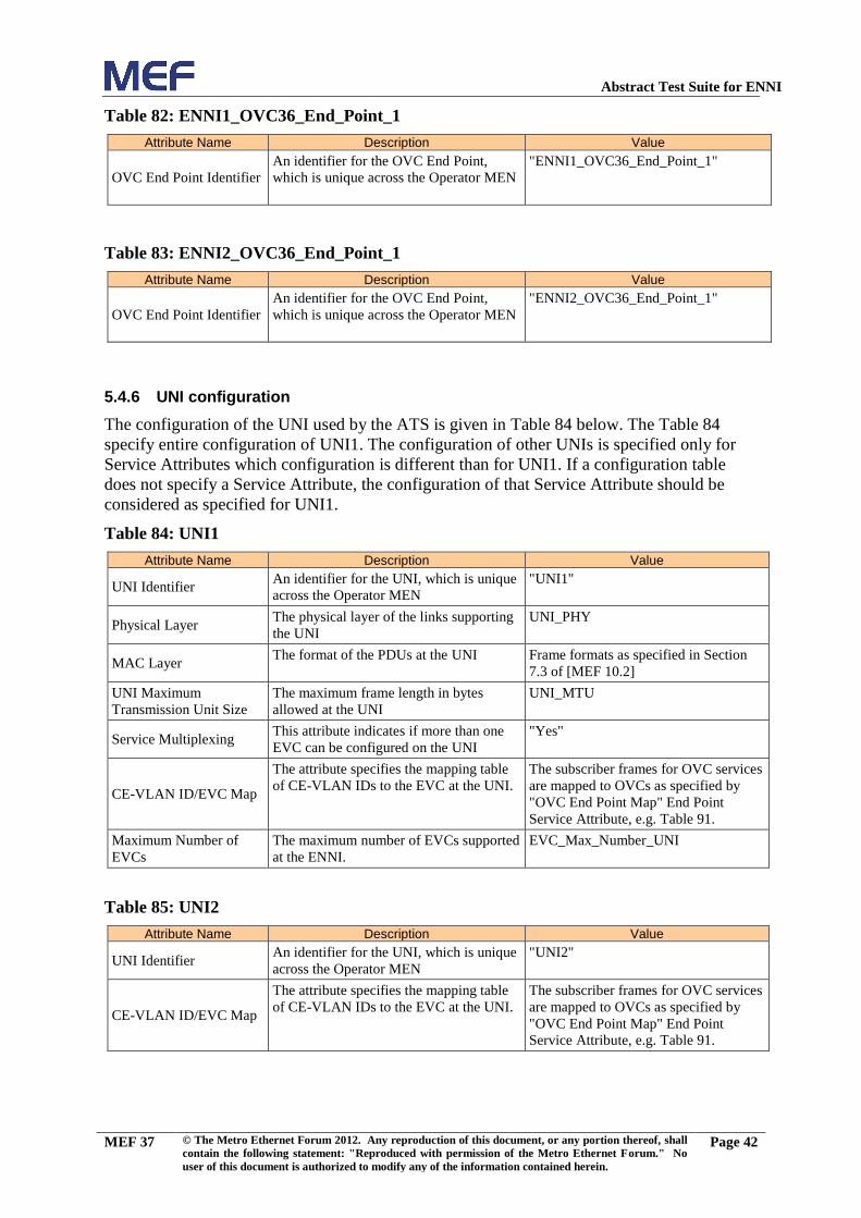
Abstract Test Suite for ENNI
MEF 37 © The Metro Ethernet Forum 2012. Any reproduction of this document, or any portion thereof, shall
contain the following statement: "Reproduced with permission of the Metro Ethernet Forum." No
user of this document is authorized to modify any of the information contained herein.
Page 42
Table 82: ENNI1_OVC36_End_Point_1
Attribute Name Description Value
OVC End Point Identifier
An identifier for the OVC End Point,
which is unique across the Operator MEN
"ENNI1_OVC36_End_Point_1"
Table 83: ENNI2_OVC36_End_Point_1
Attribute Name Description Value
OVC End Point Identifier
An identifier for the OVC End Point,
which is unique across the Operator MEN
"ENNI2_OVC36_End_Point_1"
5.4.6 UNI configuration
The configuration of the UNI used by the ATS is given in Table 84 below. The Table 84
specify entire configuration of UNI1. The configuration of other UNIs is specified only for
Service Attributes which configuration is different than for UNI1. If a configuration table
does not specify a Service Attribute, the configuration of that Service Attribute should be
considered as specified for UNI1.
Table 84: UNI1
Attribute Name Description Value
UNI Identifier An identifier for the UNI, which is unique
across the Operator MEN
"UNI1"
Physical Layer The physical layer of the links supporting
the UNI
UNI_PHY
MAC Layer The format of the PDUs at the UNI Frame formats as specified in Section
7.3 of [MEF 10.2]
UNI Maximum
Transmission Unit Size
The maximum frame length in bytes
allowed at the UNI
UNI_MTU
Service Multiplexing This attribute indicates if more than one
EVC can be configured on the UNI
"Yes"
CE-VLAN ID/EVC Map
The attribute specifies the mapping table
of CE-VLAN IDs to the EVC at the UNI.
The subscriber frames for OVC services
are mapped to OVCs as specified by
"OVC End Point Map" End Point
Service Attribute, e.g. Table 91.
Maximum Number of
EVCs
The maximum number of EVCs supported
at the ENNI.
EVC_Max_Number_UNI
Table 85: UNI2
Attribute Name Description Value
UNI Identifier An identifier for the UNI, which is unique
across the Operator MEN
"UNI2"
CE-VLAN ID/EVC Map
The attribute specifies the mapping table
of CE-VLAN IDs to the EVC at the UNI.
The subscriber frames for OVC services
are mapped to OVCs as specified by
"OVC End Point Map" End Point
Service Attribute, e.g. Table 91.

Abstract Test Suite for ENNI
MEF 37 © The Metro Ethernet Forum 2012. Any reproduction of this document, or any portion thereof, shall
contain the following statement: "Reproduced with permission of the Metro Ethernet Forum." No
user of this document is authorized to modify any of the information contained herein.
Page 43
Table 86: UNI3
Attribute Name Description Value
UNI Identifier An identifier for the UNI, which is unique
across the Operator MEN
"UNI3"
Service Multiplexing This attribute indicates if more than one
EVC can be configured on the UNI
"No"
Maximum Number of
EVCs
The maximum number of EVCs supported
at the ENNI.
1
Table 87: UNI4
Attribute Name Description Value
UNI Identifier An identifier for the UNI, which is unique
across the Operator MEN
"UNI4"
Service Multiplexing This attribute indicates if more than one
EVC can be configured on the UNI
"No"
Maximum Number of
EVCs
The maximum number of EVCs supported
at the ENNI.
1
Table 88: UNI5
Attribute Name Description Value
UNI Identifier An identifier for the UNI, which is unique
across the Operator MEN
"UNI5"
CE-VLAN ID/EVC Map
The attribute specifies the mapping table
of CE-VLAN IDs to the EVC at the UNI.
The subscriber frames for OVC services
are mapped to OVCs as specified by
"OVC End Point Map" End Point
Service Attribute, e.g. Table 91.
Table 89: UNI6
Attribute Name Description Value
UNI Identifier An identifier for the UNI, which is unique
across the Operator MEN
"UNI6"
Service Multiplexing This attribute indicates if more than one
EVC can be configured on the UNI
"No"
Maximum Number of
EVCs
The maximum number of EVCs supported
at the ENNI.
1
Table 90: UNI7
Attribute Name Description Value
UNI Identifier An identifier for the UNI, which is unique
across the Operator MEN
"UNI6"
Service Multiplexing This attribute indicates if more than one
EVC can be configured on the UNI
"No"
Maximum Number of
EVCs
The maximum number of EVCs supported
at the ENNI.
1
5.4.7 OVC per UNI configuration
The OVC per UNI configuration used by the test suite is given in Table 91 below.
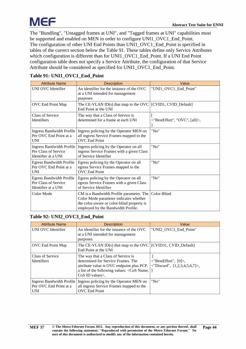
Abstract Test Suite for ENNI
MEF 37 © The Metro Ethernet Forum 2012. Any reproduction of this document, or any portion thereof, shall
contain the following statement: "Reproduced with permission of the Metro Ethernet Forum." No
user of this document is authorized to modify any of the information contained herein.
Page 44
The "Bundling", "Untagged frames at UNI", and "Tagged frames at UNI" capabilities must
be supported and enabled on MEN in order to configure UNI1_OVC1_End_Point.
The configuration of other UNI End Points than UNI1_OVC1_End_Point is specified in
tables of the currect section below the Table 91. These tables define only Service Attributes
which configuration is different than for UNI1_OVC1_End_Point. If a UNI End Point
configuration table does not specify a Service Attribute, the configuration of that Service
Attribute should be considered as specified for UNI1_OVC1_End_Point.
Table 91: UNI1_OVC1_End_Point
Attribute Name Description Value
UNI OVC Identifier An identifier for the instance of the OVC
at a UNI intended for management
purposes
"UNI1_OVC1_End_Point"
OVC End Point Map The CE-VLAN ID(s) that map to the OVC
End Point at the UNI
[CVID1, CVID_Default]
Class of Service
Identifiers
The way that a Class of Service is
determined for a frame at each UNI
[
<"BestEffort", "OVC", [all]>,
]
Ingress Bandwidth Profile
Per OVC End Point at a
UNI
Ingress policing by the Operator MEN on
all ingress Service Frames mapped to the
OVC End Point
"No"
Ingress Bandwidth Profile
Per Class of Service
Identifier at a UNI
Ingress policing by the Operator on all
ingress Service Frames with a given Class
of Service Identifier
"No"
Egress Bandwidth Profile
Per OVC End Point at a
UNI
Egress policing by the Operator on all
egress Service Frames mapped to the
OVC End Point
"No"
Egress Bandwidth Profile
Per Class of Service
Identifier at a UNI
Egress policing by the Operator on all
egress Service Frames with a given Class
of Service Identifier
"No"
Color Mode CM is a Bandwidth Profile parameter. The
Color Mode parameter indicates whether
the color-aware or color-blind property is
employed by the Bandwidth Profile.
Color-Blind
Table 92: UNI2_OVC3_End_Point
Attribute Name Description Value
UNI OVC Identifier An identifier for the instance of the OVC
at a UNI intended for management
purposes
"UNI2_OVC3_End_Point"
OVC End Point Map The CE-VLAN ID(s) that map to the OVC
End Point at the UNI
[CVID31, CVID_Default]
Class of Service
Identifiers
The way that a Class of Service is
determined for Service Frames. The
attribute value is OVC endpoint plus PCP.
a list of the following values: <CoS Name,
CoS ID values>.
[
<"BestEffort", [0]>,
<"Discard", [1,2,3,4,5,6,7]>,
]
Ingress Bandwidth Profile
Per OVC End Point at a
UNI
Ingress policing by the Operator MEN on
all ingress Service Frames mapped to the
OVC End Point
"No"

Abstract Test Suite for ENNI
MEF 37 © The Metro Ethernet Forum 2012. Any reproduction of this document, or any portion thereof, shall
contain the following statement: "Reproduced with permission of the Metro Ethernet Forum." No
user of this document is authorized to modify any of the information contained herein.
Page 45
Table 93: UNI5_OVC4_End_Point
Attribute Name Description Value
UNI OVC Identifier An identifier for the instance of the OVC
at a UNI intended for management
purposes
"UNI5_OVC4_End_Point"
OVC End Point Map The CE-VLAN ID(s) that map to the OVC
End Point at the UNI
[CVID2, CVID_Default]
Class of Service
Identifiers
The way that a Class of Service is
determined for UNI Frames. The attribute
value is a list of the following values:
<CoS Label, Color, CoS ID type, CoS ID
values>. CoS Label represents an internal
CoS label of a MEN.. CoS ID type is one
of the following: OVC, PCP (C-Tag
Priority Code Point), or DSCP. If CoS ID
type is set to OVC, CoS ID values are set
to [all].
[
<"BestEffort", ("DSCP", [0] OR “Non-
IP2”)>,
<"Discard", "DSCP", [1..63]>,
]
Ingress Bandwidth Profile
Per OVC End Point at a
UNI
Ingress policing by the Operator MEN on
all ingress Service Frames mapped to the
OVC End Point
"No"
Table 94: UNI3_OVC5_End_Point
Attribute Name Description Value
UNI OVC Identifier An identifier for the instance of the OVC
at a UNI intended for management
purposes
"UNI3_OVC5_End_Point"
OVC End Point Map The CE-VLAN ID(s) that map to the OVC
End Point at the UNI
[All CE-VLAN IDs]
Table 95: UNI4_OVC5_End_Point
Attribute Name Description Value
UNI OVC Identifier An identifier for the instance of the OVC
at a UNI intended for management
purposes
"UNI4_OVC5_End_Point"
OVC End Point Map The CE-VLAN ID(s) that map to the OVC
End Point at the UNI
[All CE-VLAN IDs]
Table 96: UNI1_OVC6_End_Point
Attribute Name Description Value
UNI OVC Identifier An identifier for the instance of the OVC
at a UNI intended for management
purposes
"UNI1_OVC6_End_Point""
OVC End Point Map The CE-VLAN ID(s) that map to the OVC
End Point at the UNI
[CVID3, CVID4]
Table 97: UNI2_OVC6_End_Point
Attribute Name Description Value
UNI OVC Identifier An identifier for the instance of the OVC
at a UNI intended for management
purposes
"UNI2_OVC6_End_Point""
2 All non-IP packets and IP packets with DSCP set to 0 are mapped to "BestEffort" class

Abstract Test Suite for ENNI
MEF 37 © The Metro Ethernet Forum 2012. Any reproduction of this document, or any portion thereof, shall
contain the following statement: "Reproduced with permission of the Metro Ethernet Forum." No
user of this document is authorized to modify any of the information contained herein.
Page 46
Attribute Name Description Value
OVC End Point Map The CE-VLAN ID(s) that map to the OVC
End Point at the UNI
[CVID5]
Table 98: UNI1_OVC10_End_Point
Attribute Name Description Value
UNI OVC Identifier An identifier for the instance of the OVC
at a UNI intended for management
purposes
"UNI1_OVC10_End_Point"
OVC End Point Map The CE-VLAN ID(s) that map to the OVC
End Point at the UNI
[CVID6]
Class of Service
Identifiers
The way that a Class of Service is
determined for UNI Frames. The attribute
value is a list of the following values:
<CoS Label, Color, CoS ID type, CoS ID
values>. CoS Label represents an internal
CoS label of a MEN. CoS ID type is one
of the following: OVC, PCP (C-Tag
Priority Code Point), or DSCP. If CoS ID
type is set to OVC, CoS ID values are set
to [all].
[
<"BestEffort", "OVC", [all]>,
]
Ingress Bandwidth Profile
Per OVC End Point at a
UNI
Ingress policing by the Operator MEN on
all ingress Service Frames mapped to the
OVC End Point
"No"
Table 99: UNI1_OVC11_End_Point
Attribute Name Description Value
UNI OVC Identifier An identifier for the instance of the OVC
at a UNI intended for management
purposes
"UNI1_OVC11_End_Point"
OVC End Point Map The CE-VLAN ID(s) that map to the OVC
End Point at the UNI
[CVID7]
Class of Service
Identifiers
The way that a Class of Service is
determined for UNI Frames. The attribute
value is a list of the following values:
<CoS Label, Color, CoS ID type, CoS ID
values>. CoS Label represents an internal
CoS label of a MEN.. CoS ID type is one
of the following: OVC, PCP (C-Tag
Priority Code Point), or DSCP. If CoS ID
type is set to OVC, CoS ID values are set
to [all].
[
<"BestEffort", "PCP", [0]>,
<"Discard", "PCP", [1,2,3,4,5,6,7]>,
]
Ingress Bandwidth Profile
Per OVC End Point at a
UNI
Ingress policing by the Operator MEN on
all ingress Service Frames mapped to the
OVC End Point
"No"
Table 100: UNI1_OVC12_End_Point
Attribute Name Description Value
UNI OVC Identifier An identifier for the instance of the OVC
at a UNI intended for management
purposes
"UNI1_OVC12_End_Point"
OVC End Point Map The CE-VLAN ID(s) that map to the OVC
End Point at the UNI
[CVID8, CVID_Default]

Abstract Test Suite for ENNI
MEF 37 © The Metro Ethernet Forum 2012. Any reproduction of this document, or any portion thereof, shall
contain the following statement: "Reproduced with permission of the Metro Ethernet Forum." No
user of this document is authorized to modify any of the information contained herein.
Page 47
Attribute Name Description Value
Class of Service
Identifiers
The way that a Class of Service is
determined for UNI Frames. The attribute
value is a list of the following values:
<CoS Label, Color, CoS ID type, CoS ID
values>. CoS Label represents an internal
CoS label of a MEN.. CoS ID type is one
of the following: OVC, PCP (C-Tag
Priority Code Point), or DSCP. If CoS ID
type is set to OVC, CoS ID values are set
to [all].
[
<"BestEffort", "DSCP", [0]>,
<"Discard", "DSCP", [1..63]>,
]
Ingress Bandwidth Profile
Per OVC End Point at a
UNI
Ingress policing by the Operator MEN on
all ingress Service Frames mapped to the
OVC End Point
"No"
Table 101: UNI1_OVC13_End_Point
Attribute Name Description Value
UNI OVC Identifier An identifier for the instance of the OVC
at a UNI intended for management
purposes
"UNI1_OVC13_End_Point"
OVC End Point Map The CE-VLAN ID(s) that map to the OVC
End Point at the UNI
[CVID10]
Table 102: UNI1_OVC14_End_Point
Attribute Name Description Value
UNI OVC Identifier An identifier for the instance of the OVC
at a UNI intended for management
purposes
"UNI1_OVC14_End_Point"
OVC End Point Map The CE-VLAN ID(s) that map to the OVC
End Point at the UNI
[CVID11]
Table 103: UNI1_OVC17_End_Point
Attribute Name Description Value
UNI OVC Identifier An identifier for the instance of the OVC
at a UNI intended for management
purposes
"UNI1_OVC17_End_Point"
OVC End Point Map The CE-VLAN ID(s) that map to the OVC
End Point at the UNI
[CVID14]

Abstract Test Suite for ENNI
MEF 37 © The Metro Ethernet Forum 2012. Any reproduction of this document, or any portion thereof, shall
contain the following statement: "Reproduced with permission of the Metro Ethernet Forum." No
user of this document is authorized to modify any of the information contained herein.
Page 48
Table 104: UNI1_OVC19_End_Point
Attribute Name Description Value
UNI OVC Identifier An identifier for the instance of the OVC
at a UNI intended for management
purposes
"UNI1_OVC19_End_Point"
OVC End Point Map The CE-VLAN ID(s) that map to the OVC
End Point at the UNI
[CVID16]
Table 105: UNI1_OVC21_End_Point
Attribute Name Description Value
UNI OVC Identifier An identifier for the instance of the OVC
at a UNI intended for management
purposes
"UNI1_OVC21_End_Point"
OVC End Point Map The CE-VLAN ID(s) that map to the OVC
End Point at the UNI
[CVID18]
Class of Service
Identifiers
The way that a Class of Service is
determined for UNI Frames. The attribute
value is a list of the following values:
<CoS Label, Color, CoS ID type, CoS ID
values>. CoS Label represents an internal
CoS label of a MEN. CoS ID type is one
of the following: OVC, PCP (C-Tag
Priority Code Point), or DSCP. If CoS ID
type is set to OVC, CoS ID values are set
to [all].
[UNI_Yellow_CoS1_IDs,
UNI_Green_CoS1_IDs,
UNI_Residual_CoS_IDs]
Ingress Bandwidth Profile
Per Class of Service
Identifier at a UNI
Ingress policing by the Operator MEN on
all ingress Service Frames mapped to the
OVC End Point The attribute specifies
mapping between Bandwidth Profile
instances and CoS Labels. The mapping is
one-to-one mapping.
CoS1:< CIR1,CBS1,0,0,0,0>
CoS2:<0,0,0,0,0,0>
Table 106: UNI1_OVC23_End_Point
Attribute Name Description Value
UNI OVC Identifier An identifier for the instance of the OVC
at a UNI intended for management
purposes
"UNI1_OVC23_End_Point"
OVC End Point Map The CE-VLAN ID(s) that map to the OVC
End Point at the UNI
[CVID20]

Abstract Test Suite for ENNI
MEF 37 © The Metro Ethernet Forum 2012. Any reproduction of this document, or any portion thereof, shall
contain the following statement: "Reproduced with permission of the Metro Ethernet Forum." No
user of this document is authorized to modify any of the information contained herein.
Page 49
Attribute Name Description Value
Class of Service
Identifiers
The way that a Class of Service is
determined for UNI Frames. The attribute
value is a list of the following values:
<CoS Label, Color, CoS ID type, CoS ID
values>. CoS Label represents an internal
CoS label of a MEN. CoS ID type is one
of the following: OVC, PCP (C-Tag
Priority Code Point), or DSCP. If CoS ID
type is set to OVC, CoS ID values are set
to [all].
[UNI_Yellow_CoS1_IDs,
UNI_Green_CoS1_IDs,
UNI_Residual_CoS_IDs]
Ingress Bandwidth Profile
Per Class of Service
Identifier at a UNI
Ingress policing by the Operator MEN on
all ingress Service Frames mapped to the
OVC End Point The attribute specifies
mapping between Bandwidth Profile
instances and CoS Labels. The mapping is
one-to-one mapping.
CoS1:< CIR1, CBS1,0,0,1,1>
CoS2:<0,0,0,0,1,1>
Table 107: UNI1_OVC24_End_Point
Attribute Name Description Value
UNI OVC Identifier An identifier for the instance of the OVC
at a UNI intended for management
purposes
"UNI1_OVC24_End_Point"
OVC End Point Map The CE-VLAN ID(s) that map to the OVC
End Point at the UNI
[CVID21]
Class of Service
Identifiers
The way that a Class of Service is
determined for UNI Frames. The attribute
value is a list of the following values:
<CoS Label, Color, CoS ID type, CoS ID
values>. CoS Label represents an internal
CoS label of a MEN. CoS ID type is one
of the following: OVC, PCP (C-Tag
Priority Code Point), or DSCP. If CoS ID
type is set to OVC, CoS ID values are set
to [all].
[UNI_Yellow_CoS1_IDs,
UNI_Green_CoS1_IDs,
UNI_Residual_CoS_IDs]
Ingress Bandwidth Profile
Per Class of Service
Identifier at a UNI
Ingress policing by the Operator MEN on
all ingress Service Frames mapped to the
OVC End Point The attribute specifies
mapping between Bandwidth Profile
instances and CoS Labels. The mapping is
one-to-one mapping.
CoS1:<0, 0, EIR1, EBS1,0,0>
CoS2:<0,0,0,0,0,0>
Table 108: UNI1_OVC26_End_Point
Attribute Name Description Value
UNI OVC Identifier An identifier for the instance of the OVC
at a UNI intended for management
purposes
"UNI1_OVC26_End_Point"
OVC End Point Map The CE-VLAN ID(s) that map to the OVC
End Point at the UNI
[CVID23]
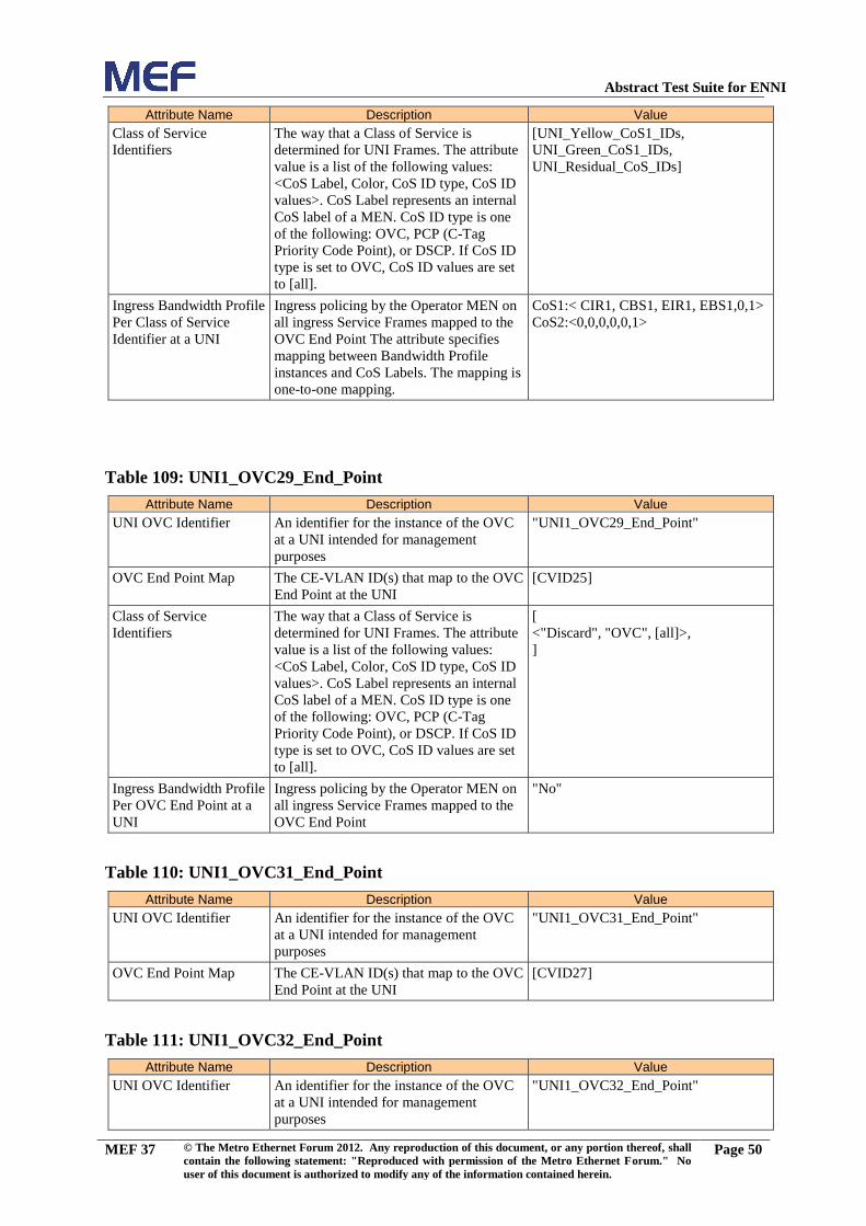
Abstract Test Suite for ENNI
MEF 37 © The Metro Ethernet Forum 2012. Any reproduction of this document, or any portion thereof, shall
contain the following statement: "Reproduced with permission of the Metro Ethernet Forum." No
user of this document is authorized to modify any of the information contained herein.
Page 50
Attribute Name Description Value
Class of Service
Identifiers
The way that a Class of Service is
determined for UNI Frames. The attribute
value is a list of the following values:
<CoS Label, Color, CoS ID type, CoS ID
values>. CoS Label represents an internal
CoS label of a MEN. CoS ID type is one
of the following: OVC, PCP (C-Tag
Priority Code Point), or DSCP. If CoS ID
type is set to OVC, CoS ID values are set
to [all].
[UNI_Yellow_CoS1_IDs,
UNI_Green_CoS1_IDs,
UNI_Residual_CoS_IDs]
Ingress Bandwidth Profile
Per Class of Service
Identifier at a UNI
Ingress policing by the Operator MEN on
all ingress Service Frames mapped to the
OVC End Point The attribute specifies
mapping between Bandwidth Profile
instances and CoS Labels. The mapping is
one-to-one mapping.
CoS1:< CIR1, CBS1, EIR1, EBS1,0,1>
CoS2:<0,0,0,0,0,1>
Table 109: UNI1_OVC29_End_Point
Attribute Name Description Value
UNI OVC Identifier An identifier for the instance of the OVC
at a UNI intended for management
purposes
"UNI1_OVC29_End_Point"
OVC End Point Map The CE-VLAN ID(s) that map to the OVC
End Point at the UNI
[CVID25]
Class of Service
Identifiers
The way that a Class of Service is
determined for UNI Frames. The attribute
value is a list of the following values:
<CoS Label, Color, CoS ID type, CoS ID
values>. CoS Label represents an internal
CoS label of a MEN. CoS ID type is one
of the following: OVC, PCP (C-Tag
Priority Code Point), or DSCP. If CoS ID
type is set to OVC, CoS ID values are set
to [all].
[
<"Discard", "OVC", [all]>,
]
Ingress Bandwidth Profile
Per OVC End Point at a
UNI
Ingress policing by the Operator MEN on
all ingress Service Frames mapped to the
OVC End Point
"No"
Table 110: UNI1_OVC31_End_Point
Attribute Name Description Value
UNI OVC Identifier An identifier for the instance of the OVC
at a UNI intended for management
purposes
"UNI1_OVC31_End_Point"
OVC End Point Map The CE-VLAN ID(s) that map to the OVC
End Point at the UNI
[CVID27]
Table 111: UNI1_OVC32_End_Point
Attribute Name Description Value
UNI OVC Identifier An identifier for the instance of the OVC
at a UNI intended for management
purposes
"UNI1_OVC32_End_Point"

Abstract Test Suite for ENNI
MEF 37 © The Metro Ethernet Forum 2012. Any reproduction of this document, or any portion thereof, shall
contain the following statement: "Reproduced with permission of the Metro Ethernet Forum." No
user of this document is authorized to modify any of the information contained herein.
Page 51
Attribute Name Description Value
OVC End Point Map The CE-VLAN ID(s) that map to the OVC
End Point at the UNI
[CVID28]
Class of Service
Identifiers
The way that a Class of Service is
determined for UNI Frames. The attribute
value is a list of the following values:
<CoS Label, Color, CoS ID type, CoS ID
values>. CoS Label represents an internal
CoS label of a MEN. CoS ID type is one
of the following: OVC, PCP (C-Tag
Priority Code Point), or DSCP. If CoS ID
type is set to OVC, CoS ID values are set
to [all].
[UNI_Yellow_CoS1_IDs,
UNI_Green_CoS1_IDs,
UNI_Residual_CoS_IDs]
Ingress Bandwidth Profile
Per Class of Service
Identifier at a UNI
Ingress policing by the Operator MEN on
all ingress Service Frames mapped to the
OVC End Point The attribute specifies
mapping between Bandwidth Profile
instances and CoS Labels. The mapping is
one-to-one mapping.
CoS1:< CIR1, CBS1, EIR1, EBS1,0,1>
CoS2:<0,0,0,0,0,1>
Table 112: UNI1_OVC34_End_Point
Attribute Name Description Value
UNI OVC Identifier An identifier for the instance of the OVC
at a UNI intended for management
purposes
"UNI1_OVC34_End_Point"
OVC End Point Map The CE-VLAN ID(s) that map to the OVC
End Point at the UNI
[CVID32]
Table 113: UNI7_OVC35_End_Point
Attribute Name Description Value
UNI OVC Identifier An identifier for the instance of the OVC
at a UNI intended for management
purposes
"UNI7_OVC35_End_Point"
OVC End Point Map The CE-VLAN ID(s) that map to the OVC
End Point at the UNI
[All CE-VLAN IDs]
Table 114: UNI1_OVC36_End_Point
Attribute Name Description Value
UNI OVC Identifier An identifier for the instance of the OVC
at a UNI intended for management
purposes
"UNI1_OVC36_End_Point"
OVC End Point Map The CE-VLAN ID(s) that map to the OVC
End Point at the UNI
[CVID26]
5.4.8 Suggested Test Flow Configuration
In all test cases the tester must monitor frames on the External Interfaces and evaluate their
format. In almost each test case a tester transmits test frames. Unless a test case procedure
otherwise stipulates, a test flow may be configured using the suggested values as specified in
Table 115, or any other reasonable values.
The terms “sent”, “transmitted” and “received” are relative to the tester unless otherwise
specified.

Abstract Test Suite for ENNI
MEF 37 © The Metro Ethernet Forum 2012. Any reproduction of this document, or any portion thereof, shall
contain the following statement: "Reproduced with permission of the Metro Ethernet Forum." No
user of this document is authorized to modify any of the information contained herein.
Page 52
Table 115: Suggested Test Flow Configuration
String ID Description Suggested Value
Frame Sizes3
MAC frame sizes of frames (without taking any C-tag or S-
Tag into account) in bytes (with FCS)
[64, 128, 512, 1024]
PCP value in CoS
ID The default PCP value used in the test frames.
0
Flow Definition
Definition of the default unidirectional traffic flow per OVC
and pair of Ethernet clients. The field "Value" defines the
flow’s frame sequence.
[Broadcast frames of "Frame
Sizes", Multicast frames of "Frame
Sizes", Unicast frames of "Frame
Sizes"]
Frame Rate /
Information Rate The rate (in fps or in bits/s) of the test traffic
1 frame per 10ms
Number of
Ethernet clients
per External
Interface and
OVC
Number of Ethernet clients per External Interface connected
over OVC
2
Flow
Transmission
Duration
The timer defines the transmission duration of the specified
flow.
120 s
Sequence
Numbers
Specifies whether the sequence numbers are used in the
payload of the test frames. The sequence numbers are used
in order to identify reordering, frame drop and duplicated
frames.
"Yes"
Reordered
Frames
Specifies if the tester accepts reordered frames on the
receive side
"Yes"
Duplicated
Frames
Specifies if the tester accepts duplicated frames on the
receive side
"Yes"
Signature A string located within frame payload that uniquely
identifies the frame as belonging to this flow in a test step.
Not specified
ToleranceFactor A factor (percentage) describing the accepted tolerance of
the bandwidth profile (policing) implementation
2 %
Table 116: Test frames A configuration
String ID Description Default Value
CoS ID The default CoS ID used in the test frames. ENNI_Green_CoS1_IDs
Frame Rate
/Information Rate The rate (in fps or in bits/s) of the test traffic
0.5*CIR1
Signature A string located within frame payload that uniquely
identifies this flow in a test step.
Not specified
Table 117: Test frames B configuration
String ID Description Default Value
Default CoS ID The default CoS ID used in the test frames. ENNI_Yellow_CoS1_IDs
Frame Rate
/Information Rate The rate (in fps or in bits/s) of the test traffic
0.5*EIR1
Signature A string located within frame payload that uniquely
identifies this flow in a test step.
Not specified
3 Tester can send untagged, priority tagged or C-tagged Service Frames at the UNI. Tester can send S-tagged
only or C-tagged and S-tagged ENNI Frames at ENNI

Abstract Test Suite for ENNI
MEF 37 © The Metro Ethernet Forum 2012. Any reproduction of this document, or any portion thereof, shall
contain the following statement: "Reproduced with permission of the Metro Ethernet Forum." No
user of this document is authorized to modify any of the information contained herein.
Page 53
5.4.9 Default Test Suite Configuration
Every test case shares a test suite specific configuration, which depends on the test method
used by the test suite. Unless a test case procedure otherwise stipulates, a test case uses test
suite specific configuration as specified in Table 118.
Table 118: Default Test Suite configuration
String ID Description Default Value
Test Case
Execution Time
Every test case runs at most "Test Case Execution Time".
The default value specified in this table may be redefined in
a particular test case. At the beginning of every test case
execution a timer with "Test Case Execution Time" is
started. If this timer timeout the test case execution will be
terminated.
Usually the test case execution will terminated before the
"Test Case Execution" timeout by receiving of a pass or
failure condition.
2*Flow Transmission Duration s
Ethernet Client
MAC Address
The MAC address of a first emulated Ethernet client. This
parameter will be specified for each emulated Ethernet
client used for the test suite execution.
00:01:01:01:01:01
Ethernet Client
MAC Address
Step
This parameter is used to automatically generate MAC
addresses of all emulated MAC clients. The MAC address
of a particular client is the MAC address of the previous
generated address plus the Ethernet Client MAC Address
Step.
00:00:00:00:00:01
Multicast MAC
Address
The multicast MAC address used during the test suite
execution.
01:01:01:01:01:01
5.4.10 Default LACP Configuration
The following table defines the default configuration of Link Aggregation Group configured
on the protected ENNI of the Operator MEN.
Table 119: Default LACP Configuration
String ID Description Value
Actor_Admin_Port_State
.LACP_Activity
This Variable indicates the Activity control value with regard to this
link. ([802.3 – 2005] section 43.4.7 and 43.4.2.2)
ACTIVE
Actor_Admin_Port_State
.LACP_Timeout
This variable indicates the Timeout control value with regard to this
link ([802.3 – 2005] section 43.4.7 and 43.4.2.2).
LONG
Actor_Admin_Port_State
.LACP_Aggregation
This variable indicates that the System considers this link to be
Aggregateable ([802.3 – 2005] section 43.4.7 and 43.4.2.2).
TRUE
Actor_Admin_Port_State
.Synchronization
If TRUE, this link has been allocated to the correct Link Aggregation
Group, the group has been associated with a compatible Aggregator,
and the identify of the Link Aggregation Group is consistent with the
System ID and operational Key information transmitted If FALSE,
then this link is not in the right Aggregation ([802.3 – 2005] section
43.4.7 and 43.4.2.2.)
FALSE
Actor_Admin_Port_State
.Collecting
TRUE means collection of incoming frames on this link is definitely
enabled; i.e., collection is currently enabled and is not expected to be
disabled in the absence of administrative changes or changes in
received protocol information. Its value is otherwise FALSE. ([802.3
– 2005] section 43.4.7 and 43.4.2.2.)
FALSE

Abstract Test Suite for ENNI
MEF 37 © The Metro Ethernet Forum 2012. Any reproduction of this document, or any portion thereof, shall
contain the following statement: "Reproduced with permission of the Metro Ethernet Forum." No
user of this document is authorized to modify any of the information contained herein.
Page 54
String ID Description Value
Actor_Admin_Port_State
.Distributing
FALSE means distribution of outgoing frames on this link is
definitely disabled; i.e., distribution is currently disabled and is not
expected to be enabled in the absence of administrative changes or
changes in received protocol information. ([802.3 – 2005] section
43.4.7 and 43.4.2.2.)
FALSE
Partner_Admin_Port_Sta
te.LACP_Activity
This Variable indicates the Activity control value with regard to this
link. ([802.3 – 2005] section 43.4.7 and 43.4.2.2.)
PASSIVE
Partner_Admin_Port_Sta
te.LACP_Timeout
This variable indicates the Timeout control value with regard to this
link ([802.3 – 2005] section 43.4.7 and 43.4.2.2).
LONG
Partner_Admin_Port_Sta
te_LACP_Aggregation
This variable indicates that the System considers this link to be
Aggregateable ([802.3 – 2005] section 43.4.7 and 43.4.2.2).
TRUE
Partner_Admin_Port_Sta
te.Synchronization
If TRUE, this link has been allocated to the correct Link Aggregation
Group, the group has been associated with a compatible Aggregator,
and the identify of the Link Aggregation Group is consistent with the
System ID and operational Key information transmitted If FALSE,
then this link is not in the right Aggregation ([802.3 – 2005] section
43.4.7 and 43.4.2.2).
FALSE
Partner_Admin_Port_Sta
te.Collecting
TRUE means collection of incoming frames on this link is definitely
enabled; i.e., collection is currently enabled and is not expected to be
disabled in the absence of administrative changes or changes in
received protocol information. Its value is otherwise FALSE ([802.3 –
2005] section 43.4.7 and 43.4.2.2.)
FALSE
Actor_Admin_Port_State
.Distributing
FALSE means distribution of outgoing frames on this link is
definitely disabled; i.e., distribution is currently disabled and is not
expected to be enabled in the absence of administrative changes or
changes in received protocol information ([802.3 – 2005] section
43.4.7 and 43.4.2.2)
FALSE
Partner_Admin_Key
Default value for the Partner’s Key, assigned by administrator or
System policy for use when the Partner’s information is unknown or
expired ([802.3 – 2005] section 43.4.7 and 43.4.2.2).
20
Actor_Admin_Aggregao
r_Key
The administrative Key value associated with the Aggregator ([802.3
– 2005] section 43.4.7 and 43.4.2.2).
40
Actor_Admin_Port_Key
The administrative value of Key assigned to this port by administrator
or System policy ([802.3 – 2005] section 43.4.7 and 43.4.2.2).
Actor_Admin_
Aggregationor_
Key
Actor_Port_Number
The port number assigned to the port ([802.3 – 2005] section 43.4.7
and 43.4.2.2).
1 for link of
ENNI
configured as
Standby, 2 for
link of ENNI
configured as
Active
5.4.11 LACP Configuration
Many test cases require the tester to send LACPDUs towards the LAG interfaces. Default
values of the LACPDU fields are provided in the "LACPDU: (Default Configuration)" table
below. The tables after the "LACPDU: (Default Configuration)" define LACPDUs that are
used by the Tester in order to trigger a special event on the LACP instance, e.g. "LACPDU:
(Request for FastMode)". These tables specify just the fields of a LACPDU that have
different value than as specified by "LACPDU: (Default Configuration)".

Abstract Test Suite for ENNI
MEF 37 © The Metro Ethernet Forum 2012. Any reproduction of this document, or any portion thereof, shall
contain the following statement: "Reproduced with permission of the Metro Ethernet Forum." No
user of this document is authorized to modify any of the information contained herein.
Page 55
Table 120: LACPDU (Default Configuration)
Segment String ID Description Value
Version Number
This identifies the LACP version; implementations
conformant to this version of the standard carry the value
0x01 ([802.3 – 2005] section 43.4.2.2).
0x01
Act
or
Info
rmat
ion
TL
V
Actor_System_Priorit
y
The priority assigned to this System (by management or
administration policy), encoded as an unsigned integer.
([802.3 – 2005] section 43.4.2.2).
0x0001
Actor_System
The Actor’s System ID, encoded as a MAC address ([802.3 –
2005] section 43.4.2.2).
01-01-01-01-
01-01
Actor_Key
The operational Key value assigned to the port by the Actor,
encoded as an unsigned integer ([802.3 – 2005] section
43.4.2.2).
Partner_Admin
_Key
Actor_Port
The port number assigned to the port by the Actor (the
System sending the PDU), encoded as an unsigned integer.
([802.3 – 2005] section 43.4.2.2).
1 for link of
ENNI
configured as
Standby, 2 for
link of ENNI
configured as
Active
Actor_Port_Priority
The priority assigned to the port by the Actor (the System
sending the PDU), encoded as an unsigned integer ([802.3 –
2005] section 43.4.2.2).
0x0001
Actor_State.LACP_Ac
tivity
This flag indicates the Activity control value with regard to
this link. ([802.3 – 2005] section 43.4.2.2)
ACTIVE
Actor_State.LACP_Ti
meout
This flag indicates the Timeout control value with regard to
this link ([802.3 – 2005] section 43.4.2.2).
LONG
Actor_State.LACP_A
ggregation
This flag indicates that the System considers this link to be
Aggregateable ([802.3 – 2005] section 43.4.2.2).
TRUE
Actor_State.Synchroni
zation
If TRUE, this link has been allocated to the correct Link
Aggregation Group, the group has been associated with a
compatible Aggregator, and the identify of the Link
Aggregation Group is consistent with the System ID and
operational Key information transmitted If FALSE, then this
link is not in the right Aggregation ([802.3 – 2005] section
43.4.2.2).
FALSE
Actor_State.Collecting
TRUE means collection of incoming frames on this link is
definitely enabled; i.e., collection is currently enabled and is
not expected to be disabled in the absence of administrative
changes or changes in received protocol information. Its
value is otherwise FALSE ([802.3 – 2005] section 43.4.2.2).
FALSE
Actor_State.Distributi
ng
FALSE means distribution of outgoing frames on this link is
definitely disabled; i.e., distribution is currently disabled and
is not expected to be enabled in the absence of administrative
changes or changes in received protocol information ([802.3
– 2005] section 43.4.2.2).
FALSE
Actor_State.Defaulted
This flag indicates that the Actor’s Receive machine is using
Defaulted operational Partner information, administratively
configured for the Partner. If FALSE, the operational Partner
information in use has been received in a LACPDU ([802.3 –
2005] section 43.4.2.2)
FALSE
Actor_State.Expired
If TRUE, this flag indicates that the Actor’s Receive
machine is in the EXPIRED state; if FALSE, this flag
indicates that the Actor Receive machine is not in the
EXPIRED state ([802.3 – 2005] section 43.4.2.2).
FALSE
Partner
Informati
on TLV
Partner_System_Priori
ty
The priority assigned to this System (by management or
administration policy), encoded as an unsigned integer
([802.3 – 2005] section 43.4.2.2).
0x0001

Abstract Test Suite for ENNI
MEF 37 © The Metro Ethernet Forum 2012. Any reproduction of this document, or any portion thereof, shall
contain the following statement: "Reproduced with permission of the Metro Ethernet Forum." No
user of this document is authorized to modify any of the information contained herein.
Page 56
Segment String ID Description Value
Partner_System The Partner’s System ID, encoded as a MAC address ([802.3
– 2005] section 43.4.2.2).
01-01-01-01-
01-02
Partner_Key
The operational Key value assigned to the port by the
Partner, encoded as an unsigned integer ([802.3 – 2005]
section 43.4.2.2).
Actor_Admin_
Aggregationor_
Key
Partner_Port_Priority The priority assigned to the port by the Partner, encoded as
an unsigned integer ([802.3 – 2005] section 43.4.2.2).
0x0001
Partner_Port ([802.3 – 2005] section 43.4.2.2). 0x0001
Partner_State.LACP_
Activity
This flag indicates the Activity control value with regard to
this link. ([802.3 – 2005] section 43.4.2.2).
ACTIVE
Partner_State.LACP_
Timeout
This flag indicates the Timeout control value with regard to
this link ([802.3 – 2005] section 43.4.2.2).
LONG
Partner_State.LACP_
Aggregation
This flag indicates that the System considers this link to be
Aggregateable ([802.3 – 2005] section 43.4.2.2).
TRUE
Partner_State.Synchro
nization
If TRUE, this link has been allocated to the correct Link
Aggregation Group, the group has been associated with a
compatible Aggregator, and the identify of the Link
Aggregation Group is consistent with the System ID and
operational Key information transmitted If FALSE, then this
link is not in the right Aggregation ([802.3 – 2005] section
43.4.2.2).
FALSE
Partner_State.Collecti
ng
TRUE means collection of incoming frames on this link is
definitely enabled; i.e., collection is currently enabled and is
not expected to be disabled in the absence of administrative
changes or changes in received protocol information. Its
value is otherwise FALSE ([802.3 – 2005] section 43.4.2.2).
FALSE
Partner_State.Distribut
ing
FALSE means distribution of outgoing frames on this link is
definitely disabled; i.e., distribution is currently disabled and
is not expected to be enabled in the absence of administrative
changes or changes in received protocol information ([802.3
– 2005] section 43.4.2.2).
FALSE
Partner_State.Defaulte
d
This flag indicates that the Actor’s Receive machine is using
Defaulted operational Partner information, administratively
configured for the Partner. If FALSE, the operational Partner
information in use has been received in a LACPDU ([802.3 –
2005] section 43.4.2.2).
FALSE
Partner_State.Expired
If TRUE, this flag indicates that the Actor’s Receive
machine is in the EXPIRED state; if FALSE, this flag
indicates that the Actor Receive machine is not in the
EXPIRED state ([802.3 – 2005] section 43.4.2.2).
FALSE
CollectorMaxDelay
This field contains the value of CollectorMaxDelay of the
station transmitting the LACPDU ([802.3 – 2005] section
43.4.2.2).
0
Table 121: LACPDU (Request for Fast Mode)
String ID Description Value
Actor_State.LACP_Timeout Some tests request the tester to send a LACPDU based on the
default configuration with change in the value of this flag
SHORT
Table 122: LACPDU (Request for detaching)
String ID Description Value
Actor_Key
Some tests request the tester to send a
LACPDU based on the default configuration
with change in the value of this flag
Actor_Admin_Aggregationor_Key
+ 1

Abstract Test Suite for ENNI
MEF 37 © The Metro Ethernet Forum 2012. Any reproduction of this document, or any portion thereof, shall
contain the following statement: "Reproduced with permission of the Metro Ethernet Forum." No
user of this document is authorized to modify any of the information contained herein.
Page 57
Table 123: LACPDU (Request for disabling Collection and Distribution)
String ID Description Value
Actor_State.Synchronization Some tests request the tester to send a LACPDU based on
the default configuration with change in the value of these
flags
FALSE
Actor_State.Collecting FALSE
Actor_State.Distributing FALSE
Table 124: LACPDU (Request for enabling Collection/disabling Distribution)
String ID Description Value
Actor_State.Synchronization Some tests request the tester to send a LACPDU based on the
default configuration with change in the value of these flags
TRUE
Actor_State.Collecting FALSE
Actor_State.Distributing FALSE
Table 125: LACPDU (Request for enabling Distribution)
String ID Description Value
Actor_State.Synchronization Some tests request the tester to send a LACPDU based on
the default configuration with change in the value of these
flags
TRUE
Actor_State.Collecting TRUE
Actor_State.Distributing FALSE
Table 126: LACPDU (Request for informing current states)
String ID Description Value
Partner_State.LACP_Activity Some tests request the tester to send a LACPDU based on
the default configuration with change in the value of this flag
PASSIVE
Table 127: LACPDU (Request for being Individual)
String ID Description Value
Partner_State.LACP_Aggregation Some tests request the tester to send a LACPDU based on
the default configuration with change in the value of this flag
FALSE
The following tables define the test traffic to be sent by the Tester towards the Operator MEN
for different test cases.
Table 128: Flow Definition1 (Default traffic flow definition)
String ID Description Value
Traffic Flow Definition 1 This is the default configuration of
traffic flow.
Test frames as defined in "Flow
Definition" in Suggested Test
Flow Configuration.
Table 129: Flow Definition2 (Traffic flow for negative test cases)
String ID Description Value
Traffic Flow Definition 2 Special unidirectional traffic flow at the
protected ENNI for negative test cases
Frames with Invalid Slow
Protocol subtype values defined
in [802.3 – 2005] Table 43B–2,
LACPDU, Marker PDU, OAM
PDU, and test frames as defined
in "Flow Definition" in Suggested
Test Flow Configuration.
The following table references default LACP timer values used by the test suite, as defined in
[802.3 – 2005], section 43.4.4.

Abstract Test Suite for ENNI
MEF 37 © The Metro Ethernet Forum 2012. Any reproduction of this document, or any portion thereof, shall
contain the following statement: "Reproduced with permission of the Metro Ethernet Forum." No
user of this document is authorized to modify any of the information contained herein.
Page 58
Table 130: LACP timers
String ID Description Value
Fast_Periodic_Time The number of seconds between periodic transmissions using Short
Timeouts ([802.3 – 2005] section 43.4.4)
1 s
Slow_Periodic_Time The number of seconds between periodic transmissions using Long
Timeouts ([802.3 – 2005] section 43.4.4)
30 s
Short_Timeout_Time
The number of seconds before invalidating received LACPDU
information when using Short Timeouts (3 x Fast_Periodic_Time) ([802.3
– 2005] section 43.4.4)
3 s
Long_Timeout_Time
The number of seconds before invalidating received LACPDU
information when using Long Timeouts (3 x Slow_Periodic_Time)
([802.3 – 2005] section 43.4.4)
90 s
The following table defines implementation-specific timing values used by the test suite. The
provided values do not represent constants, but are implementation-specific and must be
determined and filled in before executing the test suite.
Table 131: LACP-specific Parameters
Parameter Description Value
Reboot time The amount of time the LACP instance needs to perform a full Reboot
operation
300 s
LACPDU listen time The maximum time interval required by the LACP instance to generate a
LACP/Marker PDU
3 s
LACP process time The time required by a LACP instance to process the received
information.
1 s
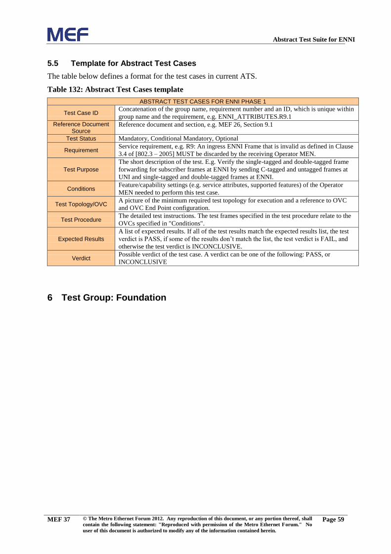
Abstract Test Suite for ENNI
MEF 37 © The Metro Ethernet Forum 2012. Any reproduction of this document, or any portion thereof, shall
contain the following statement: "Reproduced with permission of the Metro Ethernet Forum." No
user of this document is authorized to modify any of the information contained herein.
Page 59
5.5 Template for Abstract Test Cases
The table below defines a format for the test cases in current ATS.
Table 132: Abstract Test Cases template
ABSTRACT TEST CASES FOR ENNI PHASE 1
Test Case ID Concatenation of the group name, requirement number and an ID, which is unique within
group name and the requirement, e.g. ENNI_ATTRIBUTES.R9.1
Reference Document Source
Reference document and section, e.g. MEF 26, Section 9.1
Test Status Mandatory, Conditional Mandatory, Optional
Requirement Service requirement, e.g. R9: An ingress ENNI Frame that is invalid as defined in Clause
3.4 of [802.3 – 2005] MUST be discarded by the receiving Operator MEN.
Test Purpose
The short description of the test. E.g. Verify the single-tagged and double-tagged frame
forwarding for subscriber frames at ENNI by sending C-tagged and untagged frames at
UNI and single-tagged and double-tagged frames at ENNI.
Conditions Feature/capability settings (e.g. service attributes, supported features) of the Operator
MEN needed to perform this test case.
Test Topology/OVC A picture of the minimum required test topology for execution and a reference to OVC
and OVC End Point configuration.
Test Procedure The detailed test instructions. The test frames specified in the test procedure relate to the
OVCs specified in "Conditions".
Expected Results
A list of expected results. If all of the test results match the expected results list, the test
verdict is PASS, if some of the results don’t match the list, the test verdict is FAIL, and
otherwise the test verdict is INCONCLUSIVE.
Verdict Possible verdict of the test case. A verdict can be one of the following: PASS, or
INCONCLUSIVE
6 Test Group: Foundation

Abstract Test Suite for ENNI
MEF 37 © The Metro Ethernet Forum 2012. Any reproduction of this document, or any portion thereof, shall
contain the following statement: "Reproduced with permission of the Metro Ethernet Forum." No
user of this document is authorized to modify any of the information contained herein.
Page 60
6.1 PHY of ENNI Links
ABSTRACT TEST CASES FOR ENNI PHASE 1
Test Case ID ENNI_ATTRIBUTES.R5.1
Reference Document Source
MEF 26, R5
Test Status Mandatory
Requirement
Each link in an ENNI MUST be one of the following physical layers in full duplex mode as
defined in [IEEE 802.3 – 2005]: 1000Base-SX, 1000Base-LX, 1000Base T, 10GBASE-SR,
10GBASE-LX4, 10GBASE-LR, 10GBASE-ER, 10GBASE-SW, 10GBASE-LW, 10GBASE-
EW.
Test Purpose
Verify that all ENNI links operate in full duplex mode and the physical type is one of the
following: 1000Base-SX, 1000Base-LX, 1000Base T, 10GBASE-SR, 10GBASE-LX4,
10GBASE-LR, 10GBASE-ER, 10GBASE-SW, 10GBASE-LW, 10GBASE-EW.
Conditions none
Test Topology/OVC
Test Procedure Tester transmits S-Tag test frames at each ENNI, that are mapped to OVC2.
Expected Results
The physical link on each ENNI is operational
The physical link on each ENNI is one of the following types: 1000Base-SX, 1000Base-LX,
1000Base T, 10GBASE-SR, 10GBASE-LX4, 10GBASE-LR, 10GBASE-ER, 10GBASE-SW,
10GBASE-LW, 10GBASE-EW
The physical link of each ENNI operates in full duplex mode.
All test frames sent at ENNI1 are received at ENNI2.
All test frames sent at ENNI2 are received at ENNI1.
Verdict PASS, FAIL, or INCONCLUSIVE
Operator MEN
S-VID End Point ID
SVID2 ENNI1_OVC2_End_Point_1
S-VID End Point ID
SVID2 ENNI2_OVC2_End_Point_1
Test System
ENNI2
Test System
ENNI1
ENNI1_OVC2_End_Point_1
ENNI2_OVC2_End_Point_1
OVC2
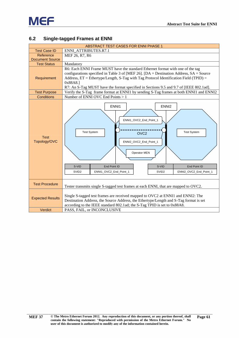
Abstract Test Suite for ENNI
MEF 37 © The Metro Ethernet Forum 2012. Any reproduction of this document, or any portion thereof, shall
contain the following statement: "Reproduced with permission of the Metro Ethernet Forum." No
user of this document is authorized to modify any of the information contained herein.
Page 61
6.2 Single-tagged Frames at ENNI
ABSTRACT TEST CASES FOR ENNI PHASE 1
Test Case ID ENNI_ATTRIBUTES.R7.1
Reference Document Source
MEF 26, R7, R6
Test Status Mandatory
Requirement
R6: Each ENNI Frame MUST have the standard Ethernet format with one of the tag
configurations specified in Table 3 of [MEF 26]. [DA = Destination Address, SA = Source
Address, ET = Ethertype/Length, S-Tag with Tag Protocol Identification Field (TPID) =
0x88A8.]
R7: An S-Tag MUST have the format specified in Sections 9.5 and 9.7 of [IEEE 802.1ad].
Test Purpose Verify the S-Tag frame format at ENNI1 by sending S-Tag frames at both ENNI1 and ENNI2
Conditions Number of ENNI OVC End Points > 1
Test Topology/OVC
Test Procedure
Tester transmits single S-tagged test frames at each ENNI, that are mapped to OVC2.
Expected Results
Single S-tagged test frames are received mapped to OVC2 at ENNI1 and ENNI2: The
Destination Address, the Source Address, the Ethertype/Length and S-Tag format is set
according to the IEEE standard 802.1ad; the S-Tag TPID is set to 0x88A8.
Verdict PASS, FAIL, or INCONCLUSIVE
Operator MEN
S-VID End Point ID
SVID2 ENNI1_OVC2_End_Point_1
S-VID End Point ID
SVID2 ENNI2_OVC2_End_Point_1
Test System
ENNI2
Test System
ENNI1
ENNI1_OVC2_End_Point_1
ENNI2_OVC2_End_Point_1
OVC2

Abstract Test Suite for ENNI
MEF 37 © The Metro Ethernet Forum 2012. Any reproduction of this document, or any portion thereof, shall
contain the following statement: "Reproduced with permission of the Metro Ethernet Forum." No
user of this document is authorized to modify any of the information contained herein.
Page 62
6.3 Double-tagged Frames at ENNI, ENNI frames
ABSTRACT TEST CASES FOR ENNI PHASE 1
Test Case ID ENNI_ATTRIBUTES.R8.2
Reference Document Source
MEF 26, R7, R6, R8
Test Status Mandatory
Requirement
R6: Each ENNI Frame MUST have the standard Ethernet format with one of the tag
configurations specified in Table 3 of [MEF 26]. [DA = Destination Address, SA = Source
Address, ET = Ethertype/Length, S-Tag with Tag Protocol Identification Field (TPID) =
0x88A8, C-Tag with TPID = 0x8100.]
R7: An S-Tag MUST have the format specified in Sections 9.5 and 9.7 of [IEEE 802.1ad].
A C-Tag MUST has the format specified in Sections 9.5 and 9.6 of [IEEE 802.1ad].
R8: A C-Tag MUST have the format specified in Sections 9.5 and 9.6 of [IEEE 802.1ad].
Test Purpose Verify the double-tagged frame format at ENNI1 by sending double-tagged frames at both
ENNI1 and ENNI2.
Conditions None
Test Topology/OVC
Test Procedure
Tester transmits double-tagged test frames at each ENNI, that are mapped to OVC2.
The inner tag (CE-VID) can be chosen arbitrarily at each ENNI, respectively.
Expected Results
Double-tagged test frames are received at ENNI1 and ENNI2, mapped to OVC2: The
Destination Address, the Source Address, the Ethertype/Length and S-Tag format are set
according to the IEEE standard 802.1ad; the TPID of the outer tag is 0x88A8, the TPID of the
inner tag is 0x8100; the TPID and CE-VID of the inner tag received at ENNI1 or ENNI2,
respectively, must match what has been transmitted at the other interface.
Verdict PASS, FAIL, or INCONCLUSIVE
Operator MEN
S-VID End Point ID
SVID2 ENNI1_OVC2_End_Point_1
S-VID End Point ID
SVID2 ENNI2_OVC2_End_Point_1
Test System
ENNI2
Test System
ENNI1
ENNI1_OVC2_End_Point_1
ENNI2_OVC2_End_Point_1
OVC2

Abstract Test Suite for ENNI
MEF 37 © The Metro Ethernet Forum 2012. Any reproduction of this document, or any portion thereof, shall
contain the following statement: "Reproduced with permission of the Metro Ethernet Forum." No
user of this document is authorized to modify any of the information contained herein.
Page 63
6.4 Single-tagged Frames at ENNI with an Invalid FCS, ENNI frames
ABSTRACT TEST CASES FOR ENNI PHASE 1
Test Case ID ENNI_ATTRIBUTES.R9.2
Reference Document Source
MEF 26, R9
Test Status Mandatory
Requirement An ingress ENNI Frame that is invalid as defined in Clause 3.4 of [802.3 – 2005] MUST be
discarded by the receiving Operator MEN.
Test Purpose Verify that if the tester sends single-tagged frames at ENNI with an invalid FCS, the Operator
MEN discards them.
Conditions Number of ENNI OVC End Points > 1
Test Topology/OVC
Test Procedure
Tester transmits single S-Tagged test frames at ENNI1, that are mapped to OVC2: the FCS is
incorrect.
Tester transmits single S-Tagged test frames at ENNI2, that are mapped to OVC2: the FCS is
incorrect.
Expected Results No test frames received at ENNI1 or at ENNI2.
Verdict PASS, FAIL, or INCONCLUSIVE
Operator MEN
S-VID End Point ID
SVID2 ENNI1_OVC2_End_Point_1
S-VID End Point ID
SVID2 ENNI2_OVC2_End_Point_1
Test System
ENNI2
Test System
ENNI1
ENNI1_OVC2_End_Point_1
ENNI2_OVC2_End_Point_1
OVC2

Abstract Test Suite for ENNI
MEF 37 © The Metro Ethernet Forum 2012. Any reproduction of this document, or any portion thereof, shall
contain the following statement: "Reproduced with permission of the Metro Ethernet Forum." No
user of this document is authorized to modify any of the information contained herein.
Page 64
6.5 Double-tagged Frames at ENNI with an Invalid FCS, ENNI frames
ABSTRACT TEST CASES FOR ENNI PHASE 1
Test Case ID ENNI_ATTRIBUTES.R9.4
Reference Document Source
MEF 26, R9
Test Status Mandatory
Requirement An ingress ENNI Frame that is invalid as defined in Clause 3.4 of [802.3 – 2005] MUST be
discarded by the receiving Operator MEN.
Test Purpose Verify that if the tester sends double-tagged frames at ENNIs with an invalid FCS, the
Operator MEN discards them.
Conditions Number of ENNI OVC End Points > 1
Test Topology/OVC
Test Procedure
Tester transmits double-tagged test frames, that are mapped to OVC2 at ENNI1: the FCS is
incorrect.
Tester transmits double-tagged test frames, that are mapped to OVC2 at ENNI2: the FCS is
incorrect.
Expected Results No test frames received at ENNI1 or ENNI2.
Verdict PASS, FAIL, or INCONCLUSIVE
Operator MEN
S-VID End Point ID
SVID2 ENNI1_OVC2_End_Point_1
S-VID End Point ID
SVID2 ENNI2_OVC2_End_Point_1
Test System
ENNI2
Test System
ENNI1
ENNI1_OVC2_End_Point_1
ENNI2_OVC2_End_Point_1
OVC2

Abstract Test Suite for ENNI
MEF 37 © The Metro Ethernet Forum 2012. Any reproduction of this document, or any portion thereof, shall
contain the following statement: "Reproduced with permission of the Metro Ethernet Forum." No
user of this document is authorized to modify any of the information contained herein.
Page 65
6.6 Discarding of Single-tagged ENNI Frames Below Minimum Size
ABSTRACT TEST CASES FOR ENNI PHASE 1
Test Case ID ENNI_ATTRIBUTES.R10.1
Reference Document Source
MEF 26, R10
Test Status Mandatory
Requirement An ingress ENNI Frame whose length is less than 64 octets MUST be discarded by the
receiving Operator MEN as per Clause 4.2.4.2.2 of [802.3 – 2005]
Test Purpose Verify that the Operator MEN discards single-tagged ENNI frames with size below 64 octets.
Conditions
Number of ENNI OVC End Points > 1
Test Topology/OVC
Test Procedure Tester transmits single S-Tagged test frames at each ENNI, that are mapped to OVC2: Frame
size is set to 63 octets.
Expected Results No test frames are received at ENNI1 or ENNI2
Verdict PASS, FAIL, or INCONCLUSIVE
Operator MEN
S-VID End Point ID
SVID2 ENNI1_OVC2_End_Point_1
S-VID End Point ID
SVID2 ENNI2_OVC2_End_Point_1
Test System
ENNI2
Test System
ENNI1
ENNI1_OVC2_End_Point_1
ENNI2_OVC2_End_Point_1
OVC2

Abstract Test Suite for ENNI
MEF 37 © The Metro Ethernet Forum 2012. Any reproduction of this document, or any portion thereof, shall
contain the following statement: "Reproduced with permission of the Metro Ethernet Forum." No
user of this document is authorized to modify any of the information contained herein.
Page 66
6.7 Discarding of Double-tagged ENNI Frames Below Minimum Size
ABSTRACT TEST CASES FOR ENNI PHASE 1
Test Case ID ENNI_ATTRIBUTES.R10.2
Reference Document Source
MEF 26, R10
Test Status Mandatory
Requirement An ingress ENNI Frame whose length is less than 64 octets MUST be discarded by the
receiving Operator MEN as per Clause 4.2.4.2.2 of [802.3 – 2005]
Test Purpose Verify that the Operator MEN discards double-tagged ENNI Frames with size below 64
octets.
Conditions Number of ENNI OVC End Points > 1
Test Topology/OVC
Test Procedure Tester transmits double-tagged test frames at each ENNI, that are mapped to OVC2: Frame
size is set to 63 octets.
Expected Results No test frames are received at ENNI1 or ENNI2.
Verdict PASS, FAIL, or INCONCLUSIVE
Operator MEN
S-VID End Point ID
SVID2 ENNI1_OVC2_End_Point_1
S-VID End Point ID
SVID2 ENNI2_OVC2_End_Point_1
Test System
ENNI2
Test System
ENNI1
ENNI1_OVC2_End_Point_1
ENNI2_OVC2_End_Point_1
OVC2

Abstract Test Suite for ENNI
MEF 37 © The Metro Ethernet Forum 2012. Any reproduction of this document, or any portion thereof, shall
contain the following statement: "Reproduced with permission of the Metro Ethernet Forum." No
user of this document is authorized to modify any of the information contained herein.
Page 67
6.8 Single-tagged Frame Forwarding at ENNI and at Maximum Frame Size
ABSTRACT TEST CASES FOR ENNI PHASE 1
Test Case ID ENNI_ATTRIBUTES.R14.1
Reference Document Source
MEF 26, R14
Test Status Mandatory
Requirement The ENNI Maximum Transmission Unit Size MUST be at least 1526 bytes.
Test Purpose Verify the single-tagged frame forwarding at ENNI MTU size.
Conditions Number of ENNI OVC End Points > 1
Test Topology/OVC
Test Procedure Tester transmits single-tagged test frames at each ENNI, that are mapped to OVC2: Frame
size is set to 1526 octets.
Expected Results All test frames are received at ENNI1 or ENNI2, are mapped to OVC2.
Verdict PASS, FAIL, or INCONCLUSIVE
Operator MEN
S-VID End Point ID
SVID2 ENNI1_OVC2_End_Point_1
S-VID End Point ID
SVID2 ENNI2_OVC2_End_Point_1
Test System
ENNI2
Test System
ENNI1
ENNI1_OVC2_End_Point_1
ENNI2_OVC2_End_Point_1
OVC2

Abstract Test Suite for ENNI
MEF 37 © The Metro Ethernet Forum 2012. Any reproduction of this document, or any portion thereof, shall
contain the following statement: "Reproduced with permission of the Metro Ethernet Forum." No
user of this document is authorized to modify any of the information contained herein.
Page 68
6.9 Double-tagged Frame Forwarding at ENNI and at Maximum Frame Size
ABSTRACT TEST CASES FOR ENNI PHASE 1
Test Case ID ENNI_ATTRIBUTES.R14.2
Reference Document Source
MEF 26, R14
Test Status Mandatory
Requirement The ENNI Maximum Transmission Unit Size MUST be at least 1526 bytes.
Test Purpose Verify the double-tagged frame forwarding at ENNI MTU size.
Conditions none
Test Topology/OVC
Test Procedure Tester transmits double-tagged test frames at each ENNI, that are mapped to OVC2: Frame
size is set to 1526 octets.
Expected Results All test frames are received at ENNI1 and ENNI2, mapped to OVC2.
Verdict PASS, FAIL, or INCONCLUSIVE
Operator MEN
S-VID End Point ID
SVID2 ENNI1_OVC2_End_Point_1
S-VID End Point ID
SVID2 ENNI2_OVC2_End_Point_1
Test System
ENNI2
Test System
ENNI1
ENNI1_OVC2_End_Point_1
ENNI2_OVC2_End_Point_1
OVC2

Abstract Test Suite for ENNI
MEF 37 © The Metro Ethernet Forum 2012. Any reproduction of this document, or any portion thereof, shall
contain the following statement: "Reproduced with permission of the Metro Ethernet Forum." No
user of this document is authorized to modify any of the information contained herein.
Page 69
6.10 Frames at ENNI Larger than MTU
ABSTRACT TEST CASES FOR ENNI PHASE 1
Test Case ID ENNI_ATTRIBUTES.R15.1
Reference Document Source
MEF 26, R15
Test Status Mandatory
Requirement
When an ENNI Frame is larger than the MTU, the receiving Operator MEN for this frame
MUST discard it, and the frame may or may not be ignored in the operation of a Bandwidth
Profile that applies to this ENNI Frame.
Test Purpose Verify that the Operator MEN discards ENNI Frames that exceed the MTU of the receiving
Operator MEN.
Conditions none
Test Topology/OVC
Test Procedure Tester transmits test frames at each ENNI, that are mapped to OVC2: Frame size is set to
"ENNI_MTU"+1 octets.
Expected Results No test frames are received at ENNI1 or ENNI2.
Verdict PASS, FAIL, or INCONCLUSIVE
Operator MEN
S-VID End Point ID
SVID2 ENNI1_OVC2_End_Point_1
S-VID End Point ID
SVID2 ENNI2_OVC2_End_Point_1
Test System
ENNI2
Test System
ENNI1
ENNI1_OVC2_End_Point_1
ENNI2_OVC2_End_Point_1
OVC2

Abstract Test Suite for ENNI
MEF 37 © The Metro Ethernet Forum 2012. Any reproduction of this document, or any portion thereof, shall
contain the following statement: "Reproduced with permission of the Metro Ethernet Forum." No
user of this document is authorized to modify any of the information contained herein.
Page 70
6.11 OVC Mapping by S-VLAN ID
ABSTRACT TEST CASES FOR ENNI PHASE 1
Test Case ID ENNI_ATTRIBUTES.R16.1
Reference Document Source
MEF 26, R16
Test Status Mandatory
Requirement For a given S-Tagged ENNI Frame, the End Point to which it is mapped MUST be
determined by the S-VLAN ID value in the S-Tag.
Test Purpose Verify that the Operator MEN selects an OVC to map the ingress frame to by its S-VLAN ID.
Conditions Number of ENNI OVC End Points > 1
Test Topology/OVC
Test Procedure
Tester transmits single S-Tagged test frames A at each ENNI, that are mapped to OVC2: the
S-VLAN ID is mapped to OVC2
Tester transmits single S-Tagged test frames B at each ENNI: the S-VLAN ID is not mapped
to any OVC
Tester transmits single S-Tagged test frames C at each ENNI, that are mapped to OVC7: the
S-VLAN IDs is mapped to OVC7
Tester transmits single S-Tagged test frames D at each ENNI: the S-VLAN IDs is not mapped
to any OVC
Expected Results
All test frames A are received at ENNI1 and ENNI2, mapped to OVC2.
No test frames B are received at any External Interfaces .
All test frames C are received at ENNI1 and ENNI2, mapped to OVC7.
No test frames D are received at ENNI1 or ENNI2.
Verdict PASS, FAIL, or INCONCLUSIVE
S-VID End Point ID
SVID3 ENNI2_OVC2_End_Point_1
SVID10 ENNI2_OVC7_End_Point_1
Operator MEN
Test System
ENNI1
S-VID End Point ID
SVID2
ENNI1_OVC2_End_Point_1
SVID9 ENNI1_OVC7_End_Point_1
Test System
ENNI2
ENNI1_OVC2_End_Point_1
OVC2
ENNI2_OVC2_End_Point_1
ENNI1_OVC7_End_Point_1
OVC7
ENNI2_OVC7_End_Point_1

Abstract Test Suite for ENNI
MEF 37 © The Metro Ethernet Forum 2012. Any reproduction of this document, or any portion thereof, shall
contain the following statement: "Reproduced with permission of the Metro Ethernet Forum." No
user of this document is authorized to modify any of the information contained herein.
Page 71
6.12 Not mapped S-Tagged ENNI Frames
ABSTRACT TEST CASES FOR ENNI PHASE 1
Test Case ID ENNI_ATTRIBUTES.R19.1
Reference Document Source
MEF 26, R19
Test Status Mandatory
Requirement An ingress S-Tagged ENNI Frame that is not mapped to an existing End Point MUST NOT
be forwarded to an External Interface by the receiving Operator MEN.
Test Purpose Verify that ingress S-Tagged ENNI Frames containing an S-VLAN ID not mapped to any
OVC are not forwarded by the receiving Operator MEN.
Conditions none
Test Topology/OVC
Test Procedure Tester transmits test frames tagged with SVID40 at each ENNI: S-VLAN ID SVID40 is not
mapped to any OVC at ENNI1 or ENNI2.
Expected Results None of the unmapped test frames are received at at ENNI1 or ENNI2.
Verdict PASS, FAIL, or INCONCLUSIVE
Operator MEN
Test System
ENNI2
Test System
ENNI1
ENNI1_OVC2_End_Point_1
ENNI2_OVC2_End_Point_1
OVC2
S-VID End Point ID
SVID2 ENNI1_OVC2_End_Point_1
SVID40
none
S-VID End Point ID
SVID2 ENNI2_OVC2_End_Point_1
SVID40
none

Abstract Test Suite for ENNI
MEF 37 © The Metro Ethernet Forum 2012. Any reproduction of this document, or any portion thereof, shall
contain the following statement: "Reproduced with permission of the Metro Ethernet Forum." No
user of this document is authorized to modify any of the information contained herein.
Page 72
6.13 Not mapped Untagged ENNI Frames
ABSTRACT TEST CASES FOR ENNI PHASE 1
Test Case ID ENNI_ATTRIBUTES.R20.1
Reference Document Source
MEF 26, R20
Test Status Mandatory
Requirement An untagged ENNI Frame MUST NOT be mapped to an OVC End Point.
Test Purpose Verify that untagged ingress ENNI Frames are not forwarded by the receiving Operator MEN.
Conditions none
Test Topology/OVC
Test Procedure Tester transmits untagged test frames at each ENNI.
Expected Results No test frames are received at ENNI1 or ENNI2.
Verdict PASS, FAIL, or INCONCLUSIVE
Operator MEN
S-VID End Point ID
SVID2 ENNI1_OVC2_End_Point_1
S-VID End Point ID
SVID2 ENNI2_OVC2_End_Point_1
Test System
ENNI2
Test System
ENNI1
ENNI1_OVC2_End_Point_1
ENNI2_OVC2_End_Point_1
OVC2
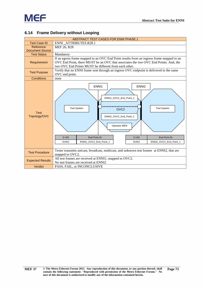
Abstract Test Suite for ENNI
MEF 37 © The Metro Ethernet Forum 2012. Any reproduction of this document, or any portion thereof, shall
contain the following statement: "Reproduced with permission of the Metro Ethernet Forum." No
user of this document is authorized to modify any of the information contained herein.
Page 73
6.14 Frame Delivery without Looping
ABSTRACT TEST CASES FOR ENNI PHASE 1
Test Case ID ENNI _ATTRIBUTES.R28.1
Reference Document Source
MEF 26, R28
Test Status Mandatory
Requirement
If an egress frame mapped to an OVC End Point results from an ingress frame mapped to an
OVC End Point, there MUST be an OVC that associates the two OVC End Points. And, the
two OVC End Points MUST be different from each other.
Test Purpose Verify that no ENNI frame sent through an ingress OVC endpoint is delivered to the same
OVC end point.
Conditions none
Test Topology/OVC
Test Procedure Tester transmits unicast, broadcast, multicast, and unknown test frames at ENNI2, that are
mapped to OVC2.
Expected Results All test frames are received at ENNI1, mapped to OVC2.
No test frames are received at ENNI2
Verdict PASS, FAIL, or INCONCLUSIVE
Operator MEN
S-VID End Point ID
SVID2 ENNI1_OVC2_End_Point_1
S-VID End Point ID
SVID2 ENNI2_OVC2_End_Point_1
Test System
ENNI2
Test System
ENNI1
ENNI1_OVC2_End_Point_1
ENNI2_OVC2_End_Point_1
OVC2

Abstract Test Suite for ENNI
MEF 37 © The Metro Ethernet Forum 2012. Any reproduction of this document, or any portion thereof, shall
contain the following statement: "Reproduced with permission of the Metro Ethernet Forum." No
user of this document is authorized to modify any of the information contained herein.
Page 74
6.15 Forwarding of Untagged Service Frames of OVC MTUSize
ABSTRACT TEST CASES FOR ENNI PHASE 1
Test Case ID OVC_ATTRIBUTES.R32.1
Reference Document Source
MEF 26, R32
Test Status Mandatory
Requirement The OVC Maximum Transmission Unit Size MUST be at least 1526 bytes.
Test Purpose Verify that the OVC is able to forward single-tagged ENNI frames with at least the size of
1526 octets.
Conditions none
Test Topology/OVC
Test Procedure Tester transmits single S-Tagged test frames at each ENNI, that are mapped to OVC2: Frame
size is set to 1526 octets.
Expected Results All test frames transmitted at ENNI1 are received at ENNI2, mapped to OVC2.
All test frames transmitted at ENNI2 are received at ENNI1, mapped to OVC2.
Verdict PASS, FAIL, or INCONCLUSIVE
Operator MEN
S-VID End Point ID
SVID2 ENNI1_OVC2_End_Point_1
S-VID End Point ID
SVID2 ENNI2_OVC2_End_Point_1
Test System
ENNI2
Test System
ENNI1
ENNI1_OVC2_End_Point_1
ENNI2_OVC2_End_Point_1
OVC2

Abstract Test Suite for ENNI
MEF 37 © The Metro Ethernet Forum 2012. Any reproduction of this document, or any portion thereof, shall
contain the following statement: "Reproduced with permission of the Metro Ethernet Forum." No
user of this document is authorized to modify any of the information contained herein.
Page 75
6.16 Forwarding of Double-Tagged ENNI Frames of OVC MTU Size
ABSTRACT TEST CASES FOR ENNI PHASE 1
Test Case ID OVC_ATTRIBUTES.R32.2
Reference Document Source
MEF 26, R32
Test Status Mandatory
Requirement The OVC Maximum Transmission Unit Size MUST be at least 1526 bytes.
Test Purpose Verify that the OVC is able to forward double-tagged ENNI frames with at least a size of
1526 octets.
Conditions none
Test Topology/OVC
Test Procedure Tester transmits double-tagged test frames at each ENNI, that are mapped to OVC2: Frame
size is set to 1526 octets
Expected Results All test frames transmitted at ENNI1 are received at ENNI2, mapped to OVC2.
All test frames transmitted at ENNI2 are received at ENNI1, mapped to OVC2.
Verdict PASS, FAIL, or INCONCLUSIVE
Operator MEN
S-VID End Point ID
SVID2 ENNI1_OVC2_End_Point_1
S-VID End Point ID
SVID2 ENNI2_OVC2_End_Point_1
Test System
ENNI2
Test System
ENNI1
ENNI1_OVC2_End_Point_1
ENNI2_OVC2_End_Point_1
OVC2

Abstract Test Suite for ENNI
MEF 37 © The Metro Ethernet Forum 2012. Any reproduction of this document, or any portion thereof, shall
contain the following statement: "Reproduced with permission of the Metro Ethernet Forum." No
user of this document is authorized to modify any of the information contained herein.
Page 76
6.17 ENNI Frames Larger Than The OVC MTU Size
ABSTRACT TEST CASES FOR ENNI PHASE 1
Test Case ID OVC_ATTRIBUTES.R33.1
Reference Document Source
MEF 26, R33
Test Status Mandatory
Requirement
When an ENNI Frame or a Service Frame is larger than the OVC MTU Size for the OVC
associating the OVC End Point to which it is mapped, the receiving Operator for this frame
MUST discard it, and the operation of a Bandwidth Profile that applies to this frame is not
defined.
Test Purpose Verify that the ENNI frames are discarded, if they are larger than the MTU size of the OVC
to which the frames are mapped.
Conditions none
Test Topology/OVC
Test Procedure Tester transmits test frames at each ENNI, that are mapped to OVC2: Frame size is set to
OVC_MTU+1 octets.
Expected Results None of the test frames may be received at any External Interface
Verdict PASS, FAIL, or INCONCLUSIVE
Operator MEN
S-VID End Point ID
SVID2 ENNI1_OVC2_End_Point_1
S-VID End Point ID
SVID2 ENNI2_OVC2_End_Point_1
Test System
ENNI2
Test System
ENNI1
ENNI1_OVC2_End_Point_1
ENNI2_OVC2_End_Point_1
OVC2

Abstract Test Suite for ENNI
MEF 37 © The Metro Ethernet Forum 2012. Any reproduction of this document, or any portion thereof, shall
contain the following statement: "Reproduced with permission of the Metro Ethernet Forum." No
user of this document is authorized to modify any of the information contained herein.
Page 77
6.18 S-VLAN ID Preservation Set to "No"
ABSTRACT TEST CASES FOR ENNI PHASE 1
Test Case ID OVC_ATTRIBUTES.R41.1
Reference Document Source
MEF 26, R41
Test Status Mandatory
Requirement
When an OVC has the S-VLAN ID Preservation attribute with a value of No, an egress ENNI
Frame mapped to an OVC End Point resulting from an ingress ENNI Frame mapped to a
different OVC End Point MUST have an S-VLAN ID value that has a one-to-one association
with the S-VLAN ID of the ingress service frame.
Test Purpose
Verify that if S-VLAN ID preservation is set to "No" for a particular OVC associated with two
ENNIs, the ENNI frames can be forwarded between the two OVC end points and the S-VLAN
IDs of the ingress and egress frames have a one-to-one association.
Conditions S-VLAN ID Preservation = "No"
Test Topology/OVC
Test Procedure Tester transmits double-tagged and single S-Tagged test frames mapped to OVC7 at ENNI1.
Tester transmits double-tagged and single S-Tagged test frames mapped to OVC7 at ENNI2.
Expected Results All test frames transmitted from ENNI1 are received at ENNI2, mapped to OVC7.
All test frames transmitted from ENNI2 are received at ENNI1, mapped to OVC7.
Verdict PASS, FAIL, or INCONCLUSIVE
Operator MEN
S-VID End Point ID
SVID9 ENNI1_OVC7_End_Point_1
S-VID End Point ID
SVID10 ENNI2_OVC7_End_Point_1
Test System
ENNI2
Test System
ENNI1
ENNI1_OVC7_End_Point_1
ENNI2_OVC7_End_Point_1
OVC7

Abstract Test Suite for ENNI
MEF 37 © The Metro Ethernet Forum 2012. Any reproduction of this document, or any portion thereof, shall
contain the following statement: "Reproduced with permission of the Metro Ethernet Forum." No
user of this document is authorized to modify any of the information contained herein.
Page 78
6.19 Unconditional Unicast frame Delivery
ABSTRACT TEST CASES FOR ENNI PHASE 1
Test Case ID OVC_ATTRIBUTES.R44.1
Reference Document Source
MEF 26, R44
Test Status Conditional Mandatory
Requirement
When the Unicast Frame Delivery is "unconditional," all properly formatted ingress frames
mapped to an OVC End Point at an External Interface with a unicast destination MAC address
MUST be delivered to all of the other OVC End Points in the OVC.
Test Purpose
Verify that all unicast ENNI Frames sent at ENNI1, ENNI2, and ENNI4 which are mapped to
an OVC are forwarded to ENNI1, ENNI2 and ENNI4, if Unconditional Unicast Frame
Delivery is enabled for the OVC over which the frames were forwarded.
Conditions Unconditional Unicast Frame Delivery = "Yes",
Number of ENNI OVC End Points > 2
Test Topology/OVC
Test Procedure
Tester transmits test frames that are mapped to OVC8 at ENNI1,: "Flow Definition" is set to
"[Unicast frames of "Frame Sizes"]"
Tester transmits test frames that are mapped to OVC8 at ENNI2: "Flow Definition" is set to
"[Unicast frames of "Frame Sizes"]"
Tester transmits test frames that are mapped to OVC8 at ENNI4: "Flow Definition" is set to
"[Unicast frames of "Frame Sizes"]".
Expected Results
All test frames transmitted at the ENNI1 are received at ENNI2 and ENNI4, mapped to
OVC8.
All test frames transmitted at ENNI2 are received at ENNI1 and ENNI4, mapped to OVC8.
All test frames transmitted at ENNI4 are received at ENNI1 and ENNI2, mapped to OVC8.
Verdict PASS, FAIL, or INCONCLUSIVE
Test System
Operator MEN
Test System
ENNI1
Test System
ENNI4
S-VID End Point ID
SVID12 ENNI2_OVC8_End_Point_1
ENNI2
S-VID End Point ID
SVID11 ENNI1_OVC8_End_Point_1
S-VID End Point ID
SVID12 ENNI4_OVC8_End_Point_1
ENNI4_OVC8_End_Point_1
ENNI2_OVC8_End_Point_1
ENNI1_OVC8_End_Point_1
OVC8

Abstract Test Suite for ENNI
MEF 37 © The Metro Ethernet Forum 2012. Any reproduction of this document, or any portion thereof, shall
contain the following statement: "Reproduced with permission of the Metro Ethernet Forum." No
user of this document is authorized to modify any of the information contained herein.
Page 79
6.20 Unconditional Multicast Frame Delivery
ABSTRACT TEST CASES FOR ENNI PHASE 1
Test Case ID OVC_ATTRIBUTES.R46.1
Reference Document Source
MEF 26, R46
Test Status Conditional Mandatory
Requirement
When the Multicast Frame Delivery is "unconditional," all properly formatted ingress frames
mapped to an OVC End Point at an External Interface with a multicast destination MAC
address MUST be delivered to all of the other End Points associated by the OVC.
Test Purpose
Verify that all multicast ENNI Frames sent at ENNI1, ENNI2 or ENNI4 are forwarded to
ENNI2 and ENNI4, or ENNI1 and ENNI4, or ENNI1 or ENNI2, if unconditional multicast
frame delivery is enabled for the OVC over which the multicast ENNI Frames were
forwarded.
Conditions Unconditional Multicast Frame Delivery = "Yes",
Number of ENNI OVC End Points > 2
Test Topology/OVC
Test Procedure
Tester transmits test frames mapped to OVC8 at ENNI1: "Flow Definition" is set to
"[Multicast frames of "Frame Sizes"]"
Tester transmits test frames mapped to OVC8 at ENNI2: "Flow Definition" is set to
"[Multicast frames of "Frame Sizes"]"
Tester transmits test frames mapped to OVC8 at ENNI4: "Flow Definition" is set to
"[Multicast frames of "Frame Sizes"]"
Expected Results
All test frames transmitted at the ENNI1 are received at both ENNI2 and ENNI4, mapped to
OVC8.
All test frames transmitted at the ENNI2 are received at both ENNI1 and ENNI4, mapped to
OVC8.
All test frames transmitted at the ENNI4 are received at both ENNI1 and ENNI2, mapped to
OVC8.
Test System
Operator MEN
Test System
ENNI1
Test System
ENNI4
S-VID End Point ID
SVID12 ENNI2_OVC8_End_Point_1
ENNI2
S-VID End Point ID
SVID11 ENNI1_OVC8_End_Point_1
S-VID End Point ID
SVID12 ENNI4_OVC8_End_Point_1
ENNI4_OVC8_End_Point_1
ENNI2_OVC8_End_Point_1
ENNI1_OVC8_End_Point_1
OVC8

Abstract Test Suite for ENNI
MEF 37 © The Metro Ethernet Forum 2012. Any reproduction of this document, or any portion thereof, shall
contain the following statement: "Reproduced with permission of the Metro Ethernet Forum." No
user of this document is authorized to modify any of the information contained herein.
Page 80
Verdict PASS, FAIL, or INCONCLUSIVE

Abstract Test Suite for ENNI
MEF 37 © The Metro Ethernet Forum 2012. Any reproduction of this document, or any portion thereof, shall
contain the following statement: "Reproduced with permission of the Metro Ethernet Forum." No
user of this document is authorized to modify any of the information contained herein.
Page 81
6.21 Unconditional Broadcast Frame Delivery
ABSTRACT TEST CASES FOR ENNI PHASE 1
Test Case ID OVC_ATTRIBUTES.R48.1
Reference Document Source
MEF 26, R48
Test Status Conditional Mandatory
Requirement
When the Broadcast Frame Delivery is "unconditional," all properly formatted ingress frames
mapped to an OVC End Point at an External Interface with the broadcast destination MAC
address MUST be delivered to all of the other OVC End Points associated by the OVC.
Test Purpose
Verify that all broadcast ENNI Frames sent at ENNI1, ENNI2 and ENNI4 are forwarded to
ENNI2 and ENNI4, or ENNI1 and ENNI4, or ENNI1 and ENNI4, if unconditional broadcast
frame delivery is enabled for the OVC over which the test frames were forwarded.
Conditions Unconditional Broadcast Frame Delivery = "Yes",
Number of ENNI OVC End Points > 2
Test Topology/OVC
Test Procedure
Tester transmits test frames that are mapped to OVC8 at ENNI1: "Flow Definition" is set to
"[Broadcast frames of "Frame Sizes"]"
Tester transmits test frames that are mapped to OVC8 at ENNI2: "Flow Definition" is set to
"[Broadcast frames of "Frame Sizes"]"
Tester transmits test frames that are mapped to OVC8 at ENNI4: "Flow Definition" is set to
"[Broadcast frames of "Frame Sizes"]"
Expected Results
All test frames transmitted at the ENNI1 are received at both ENNI2 and ENNI4, mapped to
OVC8.
All test frames transmitted at the ENNI2 are received at both ENNI1 and ENNI4, mapped to
OVC8.
All test frames transmitted at the ENNI4 are received at both ENNI1 and ENNI2, mapped to
OVC8.
Verdict PASS, FAIL, or INCONCLUSIVE
Test System
Operator MEN
Test System
ENNI1
Test System
ENNI4
S-VID End Point ID
SVID12 ENNI2_OVC8_End_Point_1
ENNI2
S-VID End Point ID
SVID11 ENNI1_OVC8_End_Point_1
S-VID End Point ID
SVID12 ENNI4_OVC8_End_Point_1
ENNI4_OVC8_End_Point_1
ENNI2_OVC8_End_Point_1
ENNI1_OVC8_End_Point_1
OVC8

Abstract Test Suite for ENNI
MEF 37 © The Metro Ethernet Forum 2012. Any reproduction of this document, or any portion thereof, shall
contain the following statement: "Reproduced with permission of the Metro Ethernet Forum." No
user of this document is authorized to modify any of the information contained herein.
Page 82
6.22 OVC End Point Selection at the UNI by the CE-VLAN ID of Tagged
Service Frames
ABSTRACT TEST CASES FOR ENNI PHASE 1
Test Case ID OVC_per_UNI_ATTRIBUTES.R66.1
Reference Document Source
MEF 26, R66
Test Status Mandatory
Requirement The OVC End Point at the UNI for a Service Frame MUST be identified by the value of CE-
VLAN ID of the Service Frame.
Test Purpose Verify that the correct OVC End Point for Service Frames on a UNI is identified by the CE-
VLAN ID of this frame.
Conditions None
Test Topology/OVC
Test Procedure
1. Tester transmits C-tagged test frames mapped to OVC11 at UNI1.
2. Tester transmits double-tagged test frames mapped to OVC11 at ENNI1.
3. Tester transmits C-tagged test frames mapped to OVC12 at UNI1.
4. Tester transmits double-tagged test frames mapped to OVC12 at ENNI1.
Expected Results
1. All test frames are received at ENNI1, mapped to OVC11
2. All test frames are received at UNI1, mapped to OVC11.
3. All test frames are received at ENNI1, mapped to OVC12
4. All test frames are received at UNI1, mapped to OVC12.
Verdict PASS, FAIL, or INCONCLUSIVE
CE-VID End Point ID
CVID7 UNI1_OVC11_End_Point
CVID8 UNI1_OVC12_End_Point
Operator MEN
Test System
UNI1
Test System
ENNI1
S-VID End Point ID
SVID15 ENNI1_OVC11_End_Point_1
SVID16 ENNI1_OVC12_End_Point_1
ENNI1_OVC11_End_Point_1
OVC11
UNI1_OVC11_End_Point
ENNI1_OVC12_End_Point_1
OVC12
UNI1_OVC12_End_Point

Abstract Test Suite for ENNI
MEF 37 © The Metro Ethernet Forum 2012. Any reproduction of this document, or any portion thereof, shall
contain the following statement: "Reproduced with permission of the Metro Ethernet Forum." No
user of this document is authorized to modify any of the information contained herein.
Page 83
6.23 Discarding of Tagged Service Frames at the UNI with CE-VLAN ID not
Mapped to any OVC End Point
ABSTRACT TEST CASES FOR ENNI PHASE 1
Test Case ID OVC_per_UNI_ATTRIBUTES.R67.1
Reference Document Source
MEF 26, R67
Test Status Mandatory
Requirement An ingress Service Frame that is not mapped to an existing OVC End Point or EVC at the
UNI MUST be discarded.
Test Purpose Verify that the Operator MEN discards Service Frames at the UNI, if the CE-VLAN ID is not
mapped to any OVC endpoints on that interface.
Conditions None
Test Topology/OVC
Test Procedure
1. Tester transmits C-tagged test frames with CVID1 mapped to OVC1 at UNI1.
2. Tester transmits C-tagged test frames with CVID2 at UNI1: the CE-VLAN ID is not
mapped to any OVC at UNI1.
3. Tester transmits untagged test frames at UNI1: the CE-VLAN ID is not mapped to any
OVC at UNI1.
4. Tester transmits Priority tagged test frames at UNI1: the CE-VLAN ID is not mapped to
any OVC at UNI1.
Expected Results 1. All test frames are received at ENNI1, mapped to OVC1.
2.-4. No test frames are received at ENNI1.
Verdict PASS, FAIL, or INCONCLUSIVE
S-VID End Point ID
SVID1 ENNI1_OVC1_End_Point_1
Operator MEN
Test System
UNI1
Test System
ENNI1
ENNI1_OVC1_End_Point_1
UNI1_OVC1_End_Point
OVC1
CE-VID End Point ID
CVID1 UNI1_OVC1_End_Point
CVID_Def
ault

Abstract Test Suite for ENNI
MEF 37 © The Metro Ethernet Forum 2012. Any reproduction of this document, or any portion thereof, shall
contain the following statement: "Reproduced with permission of the Metro Ethernet Forum." No
user of this document is authorized to modify any of the information contained herein.
Page 84
6.24 Single-tagged Frame Forwarding at ENNI Without CE-VLAN ID
Preservation
ABSTRACT TEST CASES FOR ENNI PHASE 1
Test Case ID OVC_per_UNI_ATTRIBUTES.R69.1
Reference Document Source
MEF 26, R69
Test Status Mandatory
Requirement
When an OVC associating the OVC End Point to which the CE-VLAN ID for untagged and
priority tagged Service Frames is mapped does not have the CE-VLAN ID Preservation
attribute in force, egress Service Frames for this OVC End Point at the given UNI MUST be
untagged.
Test Purpose
Verify that egress Services Frames for an OVC End Point are untagged, if the ingress Service
Frame were single S-Tagged frames at ENNI, the UNI OVC End Point has a mapping for
untagged and priority tagged Service Frames, and the OVC CE-VLAN ID Preservation
attribute is not in force.
Conditions CE-VLAN ID Preservation = "No"
Test Topology/OVC
Test Procedure Tester transmits single S-Tagged test frames mapped to OVC1 at ENNI1.
Expected Results All test frames are received at UNI1: frames are untagged.
Verdict PASS, FAIL, or INCONCLUSIVE
S-VID End Point ID
SVID1 ENNI1_OVC1_End_Point_1
Operator MEN
Test System
UNI1
Test System
ENNI1
ENNI1_OVC1_End_Point_1
UNI1_OVC1_End_Point
OVC1
CE-VID End Point ID
CVID1 UNI1_OVC1_End_Point
CVID_Default UNI1_OVC1_End_Point

Abstract Test Suite for ENNI
MEF 37 © The Metro Ethernet Forum 2012. Any reproduction of this document, or any portion thereof, shall
contain the following statement: "Reproduced with permission of the Metro Ethernet Forum." No
user of this document is authorized to modify any of the information contained herein.
Page 85
6.25 Priority C-tagged Frame Forwarding at ENNI Without CE-VLAN ID
Preservation
ABSTRACT TEST CASES FOR ENNI PHASE 1
Test Case ID OVC_per_UNI_ATTRIBUTES.R69.2
Reference Document Source
MEF 26, R69
Test Status Conditional Mandatory
Requirement
When an OVC associating the OVC End Point to which the CE-VLAN ID for untagged and
priority tagged ENNI Frames is mapped does not have the CE-VLAN ID Preservation
attribute in force, egress Service Frames for this OVC End Point at the given UNI MUST be
untagged.
Test Purpose
Verify that egress Services Frames for an OVC End Point are untagged, if the ingress ENNI
Frames were double-tagged frames at ENNI, the C-Tag of the ingress ENNI Frames was
priority tag, the OVC UNI End Point has a mapping for untagged and priority tagged Service
Frames, and the OVC CE-VLAN ID Preservation attribute is not in force.
Conditions CE-VLAN ID Preservation = "No"
Test Topology/OVC
Test Procedure Tester transmits double-tagged test frames mapped to OVC1 at ENNI1: the CE-VLAN ID is
set to 0 (priority C-tag).
Expected Results All test frames are received at UNI1: frames are untagged.
Verdict PASS, FAIL, or INCONCLUSIVE
S-VID End Point ID
SVID1 ENNI1_OVC1_End_Point_1
Operator MEN
Test System
UNI1
Test System
ENNI1
ENNI1_OVC1_End_Point_1
UNI1_OVC1_End_Point
OVC1
CE-VID End Point ID
CVID1 UNI1_OVC1_End_Point
CVID_Default UNI1_OVC1_End_Point

Abstract Test Suite for ENNI
MEF 37 © The Metro Ethernet Forum 2012. Any reproduction of this document, or any portion thereof, shall
contain the following statement: "Reproduced with permission of the Metro Ethernet Forum." No
user of this document is authorized to modify any of the information contained herein.
Page 86
6.26 C-tagged Frame Forwarding at ENNI Without CE-VLAN ID Preservation
ABSTRACT TEST CASES FOR ENNI PHASE 1
Test Case ID OVC_per_UNI_ATTRIBUTES.R69.3
Reference Document Source
MEF 26, R69
Test Status Conditional Mandatory
Requirement
When an OVC associating the OVC End Point to which the CE-VLAN ID for untagged and
Priority tagged Service Frames is mapped does not have the CE-VLAN ID Preservation
attribute in force, egress Service Frames for this OVC End Point at the given UNI MUST be
untagged.
Test Purpose
Verify that egress Services Frames for an OVC End Point are untagged, if the ingress ENNI
Frames were double-tagged frames at ENNI, the OVC UNI End Point has a mapping for
untagged Service Frames, and the OVC CE-VLAN ID Preservation attribute is not in force.
Conditions CE-VLAN ID Preservation = "No"
Test Topology/OVC
Test Procedure Tester transmits double-tagged test frames mapped to OVC1 at ENNI1: CE-VLAN ID is not 0
Expected Results All test frames are received at UNI1: frames are untagged.
Verdict PASS, FAIL, or INCONCLUSIVE
S-VID End Point ID
SVID1 ENNI1_OVC1_End_Point_1
Operator MEN
Test System
UNI1
Test System
ENNI1
ENNI1_OVC1_End_Point_1
UNI1_OVC1_End_Point
OVC1
CE-VID End Point ID
CVID1 UNI1_OVC1_End_Point
CVID_Default UNI1_OVC1_End_Point

Abstract Test Suite for ENNI
MEF 37 © The Metro Ethernet Forum 2012. Any reproduction of this document, or any portion thereof, shall
contain the following statement: "Reproduced with permission of the Metro Ethernet Forum." No
user of this document is authorized to modify any of the information contained herein.
Page 87
6.27 Determination of CoS ID on UNI – OVC End Point at UNI
ABSTRACT TEST CASES FOR ENNI PHASE 1
Test Case ID OVC_per_UNI_ATTRIBUTES.R71.1
Reference Document Source
MEF 26, R71
Test Status Conditional Mandatory
Requirement
When the Class of Service Identifier is based on OVC End Point, all ingress Data Service
Frames mapped to the same OVC End Point at the UNI MUST have the same Class of Service
Identifier.
Test Purpose Verify that the Class of Service of all Service Frames received from a single UNI End Point
on a UNI is the same, if Classifying based on OVC End Point is enabled.
Conditions Classifying based on OVC End Point = "Yes"
Test Topology/OVC
Test Procedure
Tester transmits C-tagged test frames mapped to OVC10 at UNI1: C-tag PCP is set to each of
the values in range [0..7].
Tester transmits C-tagged test frames mapped to OVC29 at UNI1: C-tag PCP is set to each of
the values in range [0..7].
Expected Results
All test frames sent over OVC10 at UNI1 are received at ENNI1, mapped to OVC10.
None of the test frames sent over OVC29 at UNI1 are received at ENNI1, mapped to OVC29.
NOTE: There is no condition on the PCP values of frames egressing on ENNI1 for this test.
Verdict PASS, FAIL, or INCONCLUSIVE
CE-VID End Point ID
CVID6 UNI1_OVC10_End_Point
CVID25 UNI1_OVC29_End_
Point
Operator MEN
Test System
UNI1
Test System
ENNI1
S-VID End Point ID
SVID14 ENNI1_OVC10_End_Point_1
SVID45 ENNI1_OVC29_En
d_Point_1
ENNI1_OVC10_End_Point_1
OVC10
UNI1_OVC10_End_Point
ENNI1_OVC29_End_Point_1
OVC29
UNI1_OVC29_End_Point

Abstract Test Suite for ENNI
MEF 37 © The Metro Ethernet Forum 2012. Any reproduction of this document, or any portion thereof, shall
contain the following statement: "Reproduced with permission of the Metro Ethernet Forum." No
user of this document is authorized to modify any of the information contained herein.
Page 88
6.28 Determination of CoS ID on UNI – C-Tag Priority Code Point
ABSTRACT TEST CASES FOR ENNI PHASE 1
Test Case ID OVC_per_UNI_ATTRIBUTES.R72.1
Reference Document Source
MEF 26, R72
Test Status Conditional Mandatory
Requirement
When the Class of Service Identifier is based on Priority Code Point field, the Class of Service
Identifier for an ingress Data Service Frame at the UNI MUST be determined by the OVC
End Point and non-overlapping sets of values of the PCP field in the C-Tag.
Test Purpose
Verify that the Class of Service of a Service Frame on a UNI is determined by the non-
overlapping sets of values of the C-Tag Priority Code Point, if the Number of UNI CoS is
greater then one.
Conditions Number of UNI CoS > 1, Classifying based on C-Tag PCP = "Yes", Discard CoS at UNI =
"Yes"
Test Topology/OVC
Test Procedure Tester transmits C-tagged test frames mapped to OVC11 at UNI1: C-tag PCP is set to each of
the values 0 (“BestEffort”), 1, 2, 3, 4, 5, 6 and 7 (“Discard”).
Expected Results
All test frames transmitted with C-tag PCP value 0 are received at ENNI1 and mapped to
OVC11.
Test frames transmitted with any other C-tag PCP values are not received at any External
Interface.
NOTE: The test procedure should not rely on egress PCP values at the ENNI but validate the
streams using the test frame signature instead.
Verdict PASS, FAIL, or INCONCLUSIVE
Test System
Operator MEN
S-VID End Point ID
SVID15 ENNI1_OVC11_End_Point_1
CE-VID End Point ID
CVID7 UNI1_OVC11_End_Point
UNI1
Test System
ENNI1
ENNI1_OVC11_End_Point_1
UNI1_OVC11_End_Point
OVC11

Abstract Test Suite for ENNI
MEF 37 © The Metro Ethernet Forum 2012. Any reproduction of this document, or any portion thereof, shall
contain the following statement: "Reproduced with permission of the Metro Ethernet Forum." No
user of this document is authorized to modify any of the information contained herein.
Page 89
6.29 Determination of CoS ID on UNI – Service Frames Without C-Tag
ABSTRACT TEST CASES FOR ENNI PHASE 1
Test Case ID OVC_per_UNI_ATTRIBUTES.R73.1
Reference Document Source
MEF 26, R73
Test Status Conditional Mandatory
Requirement
When the Class of Service Identifier is based on Priority Code Point field, if the ingress frame
does not contain a C-Tag, it MUST have the same Class of Service Identifier as an ingress
frame with Priority Code Point field = 0 in the C-Tag.
Test Purpose Verify that the Class of Service of untagged Service Frames on a UNI is mapped to the same
CoS as an ingress frame with the C-Tag Priority Code Point set to 0.
Conditions Classifying based on C-Tag PCP = "Yes" , Discard CoS at UNI = "Yes", Untagged frames at
UNI = "Yes"
Test Topology/OVC
Test Procedure Tester transmits untagged and C-Tagged frames mapped to OVC3 at UNI1: PCP of C-tagged
frames is set to each value from 0 to 7.
Expected Results
Untagged test frames and test frames with PCP=0 are received at ENNI1, mapped to OVC3.
Test frames transmitted with any other C-tag PCP values are not received at ENNI1.
NOTE: The test procedure should not rely on egress PCP values at the ENNI but validate the
streams using the test frame signature instead.
Verdict PASS, FAIL, or INCONCLUSIVE
Test System
Operator MEN
S-VID End Point ID
SVID5 ENNI1_OVC3_End_Point_1
UNI2
Test System
ENNI1
ENNI1_OVC3_End_Point_1
UNI2_OVC3_End_Point
OVC3
CE-VID End Point ID
CVID31 UNI2_OVC3_End_Point
CVID_Default
UNI2_OVC3_End_Point

Abstract Test Suite for ENNI
MEF 37 © The Metro Ethernet Forum 2012. Any reproduction of this document, or any portion thereof, shall
contain the following statement: "Reproduced with permission of the Metro Ethernet Forum." No
user of this document is authorized to modify any of the information contained herein.
Page 90
6.30 Determination of CoS ID on UNI – DSCP in IPv4
ABSTRACT TEST CASES FOR ENNI PHASE 1
Test Case ID OVC_per_UNI_ATTRIBUTES.R75.1
Reference Document Source
MEF 26, R75
Test Status Conditional Mandatory
Requirement
When the Class of Service Identifier is based on DSCP, the Class of Service Identifier for an
ingress Data Service Frame at the UNI containing an IP packet MUST be determined by the
OVC End Point and non-overlapping sets of values of the DSCP.
Test Purpose
Verify that Class of Services at UNI of the ingress frames is determined by the non-
overlapping sets of values of the DiffServ Code Points (DSCP) encoded in IPv4 ToS field, if
the Number of UNI CoS is greater then one and Classifying based on DSCP in IPv4 are
enabled.
Conditions Number of UNI CoS > 1, Classifying based on DSCP in IPv4 = "Yes", Discard CoS at UNI =
"Yes"
Test Topology/OVC
Test Procedure
Tester transmits C-tagged and untagged test frames mapped to OVC4 at UNI5: frames contain
IPv4 packets, C-tag PCP is set to 7 for C-tagged test frames, DSCP is set to each value from 0
to 63.
Expected Results
All tagged and untagged test frames transmitted with DSCP value 0 are received at ENNI1,
and mapped to OVC4.
No other test frames are received at ENNI1.
Verdict PASS, FAIL, or INCONCLUSIVE
Test System
Operator MEN
S-VID End Point ID
SVID6 ENNI1_OVC4_End_Point_1
UNI5
Test System
ENNI1
ENNI1_OVC4_End_Point_1
UNI5_OVC4_End_Point
OVC4
CE-VID End Point ID
CVID2 UNI5_OVC4_End_Point
CVID_Default
UNI5_OVC4_End_Point

Abstract Test Suite for ENNI
MEF 37 © The Metro Ethernet Forum 2012. Any reproduction of this document, or any portion thereof, shall
contain the following statement: "Reproduced with permission of the Metro Ethernet Forum." No
user of this document is authorized to modify any of the information contained herein.
Page 91
6.31 Determination of CoS ID on UNI – DSCP in IPv6
ABSTRACT TEST CASES FOR ENNI PHASE 1
Test Case ID OVC_per_UNI_ATTRIBUTES.R75.2
Reference Document Source
MEF 26, R75
Test Status Conditional Mandatory
Requirement
When the Class of Service Identifier is based on DSCP, the Class of Service Identifier for an
ingress Data Service Frame at the UNI containing an IP packet MUST be determined by the
OVC End Point and non-overlapping sets of values of the DSCP.
Test Purpose
Verify that Class of Services at UNI of the ingress frames is determined by the non-
overlapping sets of values of the DiffServ Code Points (DSCP) encoded in IPv6 Traffic Class
octet, if the Number of UNI CoS is greater then one and Classifying based on DSCP in IPv6
are enabled.
Conditions Number of UNI CoS > 1, Classifying based on DSCP in IPv6 = "Yes", Discard CoS at UNI =
"Yes"
Test Topology/OVC
Test Procedure
Tester transmits C-tagged and untagged test frames mapped to OVC4 at UNI5: frames contain
IPv6 packets, C-tag PCP is set to 7 for tagged test frames, DSCP is set to each value from 0 to
63.
Expected Results
All tagged and untagged test frames transmitted with DSCP value 0 are received at ENNI1
and mapped to OVC4.
No other test frames are received at ENNI1,
Verdict PASS, FAIL, or INCONCLUSIVE
Test System
Operator MEN
S-VID End Point ID
SVID6 ENNI1_OVC4_End_Point_1
UNI5
Test System
ENNI1
ENNI1_OVC4_End_Point_1
UNI5_OVC4_End_Point
OVC4
CE-VID End Point ID
CVID2 UNI5_OVC4_End_Point
CVID_Default
UNI5_OVC4_End_Point

Abstract Test Suite for ENNI
MEF 37 © The Metro Ethernet Forum 2012. Any reproduction of this document, or any portion thereof, shall
contain the following statement: "Reproduced with permission of the Metro Ethernet Forum." No
user of this document is authorized to modify any of the information contained herein.
Page 92
6.32 Determination of CoS ID on UNI – DSCP and Non-IP Service Frames
ABSTRACT TEST CASES FOR ENNI PHASE 1
Test Case ID OVC_per_UNI_ATTRIBUTES.R77.1
Reference Document Source
MEF 26, R77
Test Status Conditional Mandatory
Requirement
When the Class of Service Identifier is based on DSCP, each ingress Data Service Frame at
the UNI not containing an IP packet and mapped to a given OVC End Point MUST have the
same Class of Service Identifier with a value agreed upon by the Operator and the Service
Provider.
Test Purpose Verify that the Class of Service of Service Frames on a UNI not containing an IP packet is
mapped to the same CoS agreed upon by the Operator and the Service Provider.
Conditions Number of UNI OVC End Points > 0, (Classifying based on DSCP in IPv4 or Classifying
based on DSCP in IPv6) = "Yes",
Test Topology/OVC
Test Procedure
Tester transmits C-tagged and untagged test frames mapped to OVC4 at UNI5: frames contain
non-IP and IP packets, PCP of tagged frames is set to each value from 0 to 7, DSCP value of
IP packets is set to each value from 0 to 63.
Expected Results
All non-IP and IP packets transmitted with DSCP value 0 are received at ENNI1, and mapped
to OVC4.
No other test frames are received at ENNI1.
Verdict PASS, FAIL, or INCONCLUSIVE
Test System
Operator MEN
S-VID End Point ID
SVID6 ENNI1_OVC4_End_Point_1
UNI5
Test System
ENNI1
ENNI1_OVC4_End_Point_1
UNI5_OVC4_End_Point
OVC4
CE-VID End Point ID
CVID2 UNI5_OVC4_End_Point
CVID_Default
UNI5_OVC4_End_Point

Abstract Test Suite for ENNI
MEF 37 © The Metro Ethernet Forum 2012. Any reproduction of this document, or any portion thereof, shall
contain the following statement: "Reproduced with permission of the Metro Ethernet Forum." No
user of this document is authorized to modify any of the information contained herein.
Page 93
7 Test Group: Protection
For sake of simplicity, all test cases in this section use the same topology with one protected
ENNI and one UNI, and a single point-to-point OVC configured between the ENNI and UNI.
In some test cases, the test procedure is limited to behavior at the ENNI. For these cases, the
expected results do not require configuration of OVC, UNI and test traffic across the OVC.
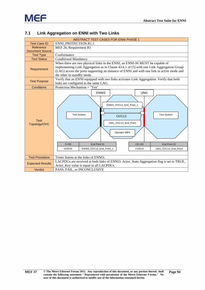
Abstract Test Suite for ENNI
MEF 37 © The Metro Ethernet Forum 2012. Any reproduction of this document, or any portion thereof, shall
contain the following statement: "Reproduced with permission of the Metro Ethernet Forum." No
user of this document is authorized to modify any of the information contained herein.
Page 94
7.1 Link Aggregation on ENNI with Two Links
ABSTRACT TEST CASES FOR ENNI PHASE 1
Test Case ID ENNI_PROTECTION.R1.1
Reference Document Source
MEF 26, Requirement R1
Test Type Conformance
Test Status Conditional Mandatory
Requirement
When there are two physical links in the ENNI, an ENNI-Ni MUST be capable of
implementing Link Aggregation as in Clause 43.6.1 of [5] with one Link Aggregation Group
(LAG) across the ports supporting an instance of ENNI and with one link in active mode and
the other in standby mode.
Test Purpose Verify that an ENNI equipped with two links activates Link Aggregation. Verify that both
links are configured in the same LAG.
Conditions Protection Mechanism = "Yes"
Test Topology/OVC
Test Procedure Tester listens at the links of ENNI3.
Expected Results LACPDUs are received at both links of ENNI3: Actor_State.Aggregation flag is set to TRUE,
Actor_Key value is equal in all LACPDUs.
Verdict PASS, FAIL, or INCONCLUSIVE
Test System
Operator MEN
S-VID End Point ID
SVID34 ENNI3_OVC13_End_Point_1
CE-VID End Point ID
CVID10 UNI1_OVC13_End_Point
UNI1
Test System
ENNI3
ENNI3_OVC13_End_Point_1
UNI1_OVC13_End_Point
OVC13

Abstract Test Suite for ENNI
MEF 37 © The Metro Ethernet Forum 2012. Any reproduction of this document, or any portion thereof, shall
contain the following statement: "Reproduced with permission of the Metro Ethernet Forum." No
user of this document is authorized to modify any of the information contained herein.
Page 95
7.2 Basic Interconnection: LACP
ABSTRACT TEST CASES FOR ENNI PHASE 1
Test Case ID ENNI_PROTECTION.R2.1
Reference Document Source
MEF 26, Requirement R2
Test Type Conformance
Test Status Conditional Mandatory
Requirement When Link Aggregation is used at the ENNI, LACP MUST be used by each ENNI-Ni per
[5].
Test Purpose Verify that the Operator MEN component with ENNI functionality sends LACPDU at each
link on the protected ENNI to initiate the link aggregation.
Conditions LAG = "Yes"
Test Topology/OVC
Test Procedure Tester listens for up to (LACP process time + LACPDU listen time + Slow_Periodic_Time)
seconds at the links of ENNI3.
Expected Results At least one LACPDU must be received at each of the links of ENNI3.
Verdict PASS, FAIL, or INCONCLUSIVE
Test System
Operator MEN
S-VID End Point ID
SVID34 ENNI3_OVC13_End_Point_1
CE-VID End Point ID
CVID10 UNI1_OVC13_End_Point
UNI1
Test System
ENNI3
ENNI3_OVC13_End_Point_1
UNI1_OVC13_End_Point
OVC13

Abstract Test Suite for ENNI
MEF 37 © The Metro Ethernet Forum 2012. Any reproduction of this document, or any portion thereof, shall
contain the following statement: "Reproduced with permission of the Metro Ethernet Forum." No
user of this document is authorized to modify any of the information contained herein.
Page 96
7.3 Active Link in the Protection LAG
ABSTRACT TEST CASES FOR ENNI PHASE 1
Test Case ID ENNI_PROTECTION.R1.2
Reference Document Source
MEF 26, Requirement R1
Test Type Conformance
Test Status Conditional Mandatory
Requirement
When there are two physical links in the ENNI, an ENNI-Ni MUST be capable of
implementing Link Aggregation as in Clause 43.6.1 of [5] with one Link Aggregation Group
(LAG) across the ports supporting an instance of ENNI and with one link in active mode and
the other in standby mode.
Test Purpose Verify that in the Link Aggregation Group configured in the ENNI contains one active link.
Conditions LAG = "Yes"
Test Topology/OVC
Test Procedure
Tester transmits a LACPDU (Request for enabling Distribution) at the link of ENNI3
configured as Active.
Tester sends test frames Flow Definition1 (Default traffic flow definition) at UNI1 and at the
link ofENNI3 configured as Active: the test frames are mapped to OVC13.
Expected Results All test frames sent at ENNI3 are received at UNI1.
Verdict PASS, FAIL, or INCONCLUSIVE
Test System
Operator MEN
S-VID End Point ID
SVID34 ENNI3_OVC13_End_Point_1
CE-VID End Point ID
CVID10 UNI1_OVC13_End_Point
UNI1
Test System
ENNI3
ENNI3_OVC13_End_Point_1
UNI1_OVC13_End_Point
OVC13

Abstract Test Suite for ENNI
MEF 37 © The Metro Ethernet Forum 2012. Any reproduction of this document, or any portion thereof, shall
contain the following statement: "Reproduced with permission of the Metro Ethernet Forum." No
user of this document is authorized to modify any of the information contained herein.
Page 97
7.4 Passive Link in the Protection LAG
ABSTRACT TEST CASES FOR ENNI PHASE 1
Test Case ID ENNI_PROTECTION.R1.3
Reference Document Source
MEF 26, Requirement R1
Test Type Conformance
Test Status Conditional Mandatory
Requirement
When there are two physical links in the ENNI, an ENNI-Ni MUST be capable of
implementing Link Aggregation as in Clause 43.6.1 of [5] with one Link Aggregation Group
(LAG) across the ports supporting an instance of ENNI and with one link in active mode and
the other in standby mode.
Test Purpose Verify that in the Link Aggregation Group configured in the ENNI contains one passive
(standby) link.
Conditions LAG = "Yes"
Test Topology/OVC
Test Procedure
Tester transmits a LACPDU (Request for disabling Collection and Distribution) at the link of
ENNI3 configured as Standby.
Tester transmits test frames Flow Definition1 (Default traffic flow definition) at UNI1 and at
the link of ENNI3 configured as Standby: the test frames are mapped to OVC13.
Expected Results Test frames are not received on the standby or active link of ENNI3 or at UNI1.
Verdict PASS, FAIL, or INCONCLUSIVE
Test System
Operator MEN
S-VID End Point ID
SVID34 ENNI3_OVC13_End_Point_1
CE-VID End Point ID
CVID10 UNI1_OVC13_End_Point
UNI1
Test System
ENNI3
ENNI3_OVC13_End_Point_1
UNI1_OVC13_End_Point
OVC13

Abstract Test Suite for ENNI
MEF 37 © The Metro Ethernet Forum 2012. Any reproduction of this document, or any portion thereof, shall
contain the following statement: "Reproduced with permission of the Metro Ethernet Forum." No
user of this document is authorized to modify any of the information contained herein.
Page 98
7.5 Aggregator Parser–forward valid frames (Collection)
ABSTRACT TEST CASES FOR ENNI PHASE 1
Test Case ID LA_OPERATION.APM3.1
Reference Document Source
IEEE Std 802.3 – 2005, Clause 43.2.7; Protocol implementation conformance statement
(PICS) proforma for Clause 43, Item APM3
Test Type Conformance
Test Status Conditional Mandatory
Requirement Function specified by state diagram shown in Figure 43–5 and associated definitions in
43.2.7.1
Test Purpose Verify that the Operator MEN component with ENNI functionality doesn’t forward any Slow
Protocol PDUs with invalid Protocol Subtype value or LACP/Marker PDUs to the EIs.
Conditions LAG = "Yes"
Test Topology/OVC
Test Procedure
Tester transmits a LACPDU (Request for enabling Collection/disabling Distribution) at each
link of ENNI3
Tester transmits test frames Flow Definition2 (Traffic flow for negative test cases) mapped to
OVC13 at ENNI3
Expected Results Slow Protocol PDUs with invalid Protocol Subtype value or LACP/Marker PDUs are not
received on the standby or active link of ENNI3 or at UNI1.
Verdict PASS, FAIL, or INCONCLUSIVE
Test System
Operator MEN
S-VID End Point ID
SVID34 ENNI3_OVC13_End_Point_1
CE-VID End Point ID
CVID10 UNI1_OVC13_End_Point
UNI1
Test System
ENNI3
ENNI3_OVC13_End_Point_1
UNI1_OVC13_End_Point
OVC13

Abstract Test Suite for ENNI
MEF 37 © The Metro Ethernet Forum 2012. Any reproduction of this document, or any portion thereof, shall
contain the following statement: "Reproduced with permission of the Metro Ethernet Forum." No
user of this document is authorized to modify any of the information contained herein.
Page 99
7.6 Aggregator Parser–discard frames (No Collection)
ABSTRACT TEST CASES FOR ENNI PHASE 1
Test Case ID LA_OPERATION.APM4.1
Reference Document Source
IEEE Std 802.3 – 2005, Clause 43.2.7; Protocol implementation conformance statement
(PICS) proforma for Clause 43, Item APM4
Test Type Conformance
Test Status Conditional Mandatory
Requirement
Function specified by state diagram shown in Figure 43–5 and associated definitions in
43.2.7.1
The Aggregator Parser shall pass all other frames to the Frame Collector for passage to the
MAC Client only when the port state is Collecting; otherwise such frames shall be discarded.
Test Purpose
Verify that the Operator MEN component with ENNI functionality, when the ports on the
protected ENNI are NOT in the Collecting state, doesn’t forward any frames from the ENNI
to the EIs.
Conditions LAG = "Yes"
Test Topology/OVC
Test Procedure
Tester transmits a LACPDU (Request for disabling Collection and Distribution) at each link
of ENNI3
Tester transmits test frames Flow Definition2 (Traffic flow for negative test cases) mapped to
OVC13 at ENNI3
Expected Results Test frames are not received on the standby or active link of ENNI3 or at UNI1.
Verdict PASS, FAIL, or INCONCLUSIVE
Test System
Operator MEN
S-VID End Point ID
SVID34 ENNI3_OVC13_End_Point_1
CE-VID End Point ID
CVID10 UNI1_OVC13_End_Point
UNI1
Test System
ENNI3
ENNI3_OVC13_End_Point_1
UNI1_OVC13_End_Point
OVC13

Abstract Test Suite for ENNI
MEF 37 © The Metro Ethernet Forum 2012. Any reproduction of this document, or any portion thereof, shall
contain the following statement: "Reproduced with permission of the Metro Ethernet Forum." No
user of this document is authorized to modify any of the information contained herein.
Page
100
7.7 Aggregator Parser–forward Marker PDUs (Collection)
ABSTRACT TEST CASES FOR ENNI PHASE 1
Test Case ID LA_OPERATION.APM3.2
Reference Document Source
IEEE Std 802.3 – 2005, Clause 43.2.7; Protocol implementation conformance statement
(PICS) proforma for Clause 43, Item APM3
Test Type Conformance
Test Status Conditional Mandatory
Requirement Function specified by state diagram shown in Figure 43–5 and associated definitions in
43.2.7.1
Test Purpose
Verify that the Operator MEN component with ENNI functionality, when the ports on the
protected ENNI are in the Collecting state, forwards Marker PDUs from the ENNI to the
Marker Responder. On receipt of a Marker PDU the Marker Responder sends a Marker PDU
for answering.
Conditions LAG = "Yes"
Test Topology/OVC
Test Procedure
Tester transmits a LACPDU (Request for enabling Collection/disabling Distribution) at each
link of ENNI3
Tester transmits a Marker PDU at each link of ENNI3
Expected Results Marker PDU is received at the link of ENNI3 configured as Active.
Marker PDU is not received at the link of ENNI3 configured as Standby.
Verdict PASS, FAIL, or INCONCLUSIVE
Test System
Operator MEN
S-VID End Point ID
SVID34 ENNI3_OVC13_End_Point_1
CE-VID End Point ID
CVID10 UNI1_OVC13_End_Point
UNI1
Test System
ENNI3
ENNI3_OVC13_End_Point_1
UNI1_OVC13_End_Point
OVC13

Abstract Test Suite for ENNI
MEF 37 © The Metro Ethernet Forum 2012. Any reproduction of this document, or any portion thereof, shall
contain the following statement: "Reproduced with permission of the Metro Ethernet Forum." No
user of this document is authorized to modify any of the information contained herein.
Page
101
7.8 Aggregator Parser–forward Marker PDUs (No Collection)
ABSTRACT TEST CASES FOR ENNI PHASE 1
Test Case ID LA_OPERATION.APM3.4
Reference Document Source
IEEE Std 802.3 – 2005, Clause 43.2.7; Protocol implementation conformance statement
(PICS) proforma for Clause 43, Item APM3
Test Type Conformance
Test Status Conditional Mandatory
Requirement Function specified by state diagram shown in Figure 43–5 and associated definitions in
43.2.7.1
Test Purpose
Verify that the Operator MEN component with ENNI functionality, when the ports on the
protected ENNI are NOT in the Collecting state, forwards Marker PDUs from the ENNI to the
Marker Responder. On receipt of a Marker PDU the Marker Responder should send a Marker
PDU for answering.
Conditions LAG = "Yes"
Test Topology/OVC
Test Procedure
Tester transmits a LACPDU (Request for enabling Collection/disabling Distribution) at each
link of ENNI3
Tester transmits Marker PDU at each link of ENNI3
Expected Results Marker PDU is received at the link of ENNI3 configured as Active.
Marker PDU is not received at the link of ENNI3 configured as Standby.
Verdict PASS, FAIL, or INCONCLUSIVE
Test System
Operator MEN
S-VID End Point ID
SVID34 ENNI3_OVC13_End_Point_1
CE-VID End Point ID
CVID10 UNI1_OVC13_End_Point
UNI1
Test System
ENNI3
ENNI3_OVC13_End_Point_1
UNI1_OVC13_End_Point
OVC13

Abstract Test Suite for ENNI
MEF 37 © The Metro Ethernet Forum 2012. Any reproduction of this document, or any portion thereof, shall
contain the following statement: "Reproduced with permission of the Metro Ethernet Forum." No
user of this document is authorized to modify any of the information contained herein.
Page
102
7.9 Aggregator Parser–discard invalid Marker PDUs–inopportune
ABSTRACT TEST CASES FOR ENNI PHASE 1
Test Case ID LA_OPERATION.APM3.6
Reference Document Source
IEEE Std 802.3 – 2005, Clause 43.2.7; Protocol implementation conformance statement
(PICS) proforma for Clause 43, Item APM3
Test Type Conformance
Test Status Conditional Mandatory
Requirement Function specified by state diagram shown in Figure 43–5 and associated definitions in
43.2.7.1
Test Purpose Verify that the Operator MEN component with ENNI functionality discards invalid Marker
PDUs received at ENNI3.
Conditions LAG = "Yes"
Test Topology/OVC
Test Procedure
Tester transmits a LACPDU (Request for disabling Collection and Distribution) at each link
of ENNI3
Tester transmits a Marker PDU at each link of ENNI3
Expected Results Marker PDU is not received on the standby or active link of ENNI3 or at UNI1.
Verdict PASS, FAIL, or INCONCLUSIVE
Test System
Operator MEN
S-VID End Point ID
SVID34 ENNI3_OVC13_End_Point_1
CE-VID End Point ID
CVID10 UNI1_OVC13_End_Point
UNI1
Test System
ENNI3
ENNI3_OVC13_End_Point_1
UNI1_OVC13_End_Point
OVC13

Abstract Test Suite for ENNI
MEF 37 © The Metro Ethernet Forum 2012. Any reproduction of this document, or any portion thereof, shall
contain the following statement: "Reproduced with permission of the Metro Ethernet Forum." No
user of this document is authorized to modify any of the information contained herein.
Page
103
7.10 Aggregator Multiplexer–forward Marker PDU (No Distribution)
ABSTRACT TEST CASES FOR ENNI PHASE 1
Test Case ID LA_OPERATION.APM1.1
Reference Document Source
IEEE Std 802.3 – 2005, Clause 43.2.7; Protocol implementation conformance statement
(PICS) proforma for Clause 43, Item APM1
Test Type Conformance
Test Status Conditional Mandatory
Requirement
On transmission, the Aggregator Multiplexer shall provide transparent pass-through of frames
submitted by the Marker Responder and optional Marker Generator to the port specified in the
transmission request.
Test Purpose
Verify that the Operator MEN component with ENNI functionality, when the ports on the
protected ENNI are NOT in the Distributing state, forwards Marker PDUs submitted by the
Marker Responder to the ENNI.
Conditions LAG = "Yes"
Test Topology/OVC
Test Procedure
Tester transmits a LACPDU (Request for enabling Collection/disabling Distribution) at each
link of ENNI3.
Tester transmits a Marker PDU at each link of ENNI3.
Expected Results Marker PDU is received at the link of ENNI3 configured as Active.
Marker PDU is not received at the link of ENNI3 configured as Standby.
Verdict PASS, FAIL, or INCONCLUSIVE
Test System
Operator MEN
S-VID End Point ID
SVID34 ENNI3_OVC13_End_Point_1
CE-VID End Point ID
CVID10 UNI1_OVC13_End_Point
UNI1
Test System
ENNI3
ENNI3_OVC13_End_Point_1
UNI1_OVC13_End_Point
OVC13

Abstract Test Suite for ENNI
MEF 37 © The Metro Ethernet Forum 2012. Any reproduction of this document, or any portion thereof, shall
contain the following statement: "Reproduced with permission of the Metro Ethernet Forum." No
user of this document is authorized to modify any of the information contained herein.
Page
104
7.11 Aggregator Multiplexer– forward Marker PDU (Distribution)
ABSTRACT TEST CASES FOR ENNI PHASE 1
Test Case ID LA_OPERATION.APM1.3
Reference Document Source
IEEE Std 802.3 – 2005, Clause 43.2.7; Protocol implementation conformance statement
(PICS) proforma for Clause 43, Item APM1
Test Type Conformance
Test Status Conditional Mandatory
Requirement
On transmission, the Aggregator Multiplexer shall provide transparent pass-through of frames
submitted by the Marker Responder and optional Marker Generator to the port specified in the
transmission request.
Test Purpose
Verify that the Operator MEN component with ENNI functionality, when the ports on the
protected ENNI are in the Distributing state, forwards Marker PDUs submitted by the Marker
Responder to the ENNI.
Conditions LAG = "Yes"
Test Topology/OVC
Test Procedure Tester transmits a LACPDU (Request for enabling Distribution) at each link of ENNI3.
Tester transmits a Marker PDU at each link of ENNI3.
Expected Results Marker PDU is received at the link of ENNI3 configured as Active.
Marker PDU is not received at the link of ENNI3 configured as Standby.
Verdict PASS, FAIL, or INCONCLUSIVE
Test System
Operator MEN
S-VID End Point ID
SVID34 ENNI3_OVC13_End_Point_1
CE-VID End Point ID
CVID10 UNI1_OVC13_End_Point
UNI1
Test System
ENNI3
ENNI3_OVC13_End_Point_1
UNI1_OVC13_End_Point
OVC13
Abstract Test Suite for ENNI
MEF 37 © The Metro Ethernet Forum 2012. Any reproduction of this document, or any portion thereof, shall
contain the following statement: "Reproduced with permission of the Metro Ethernet Forum." No
user of this document is authorized to modify any of the information contained herein.
Page
105
7.12 Aggregator Multiplexer–forward frames (Distribution)
ABSTRACT TEST CASES FOR ENNI PHASE 1
Test Case ID LA_OPERATION.APM1.5
Reference Document Source
IEEE Std 802.3 – 2005, Clause 43.2.7; Protocol implementation conformance statement
(PICS) proforma for Clause 43, Item APM1
Test Type Conformance
Test Status Conditional Mandatory
Requirement
The Aggregator Multiplexer shall provide transparent pass-through of frames submitted by the
Frame Distributor to the port specified in the transmission request only when the port state is
Distributing;
Test Purpose Verify that the Operator MEN component with ENNI functionality, when the ports on the
protected ENNI are in the Distributing state, forwards frames from the EIs to the ENNI.
Conditions LAG = "Yes"
Test Topology/OVC
Test Procedure
Tester transmits a LACPDU (Request for enabling Distribution) at each link of ENNI3.
Tester transmits test frames Flow Definition1 (Default traffic flow definition) mapped to
OVC13 at UNI1.
Expected Results All test frames are received at ENNI3.
Verdict PASS, FAIL, or INCONCLUSIVE
Test System
Operator MEN
S-VID End Point ID
SVID34 ENNI3_OVC13_End_Point_1
CE-VID End Point ID
CVID10 UNI1_OVC13_End_Point
UNI1
Test System
ENNI3
ENNI3_OVC13_End_Point_1
UNI1_OVC13_End_Point
OVC13

Abstract Test Suite for ENNI
MEF 37 © The Metro Ethernet Forum 2012. Any reproduction of this document, or any portion thereof, shall
contain the following statement: "Reproduced with permission of the Metro Ethernet Forum." No
user of this document is authorized to modify any of the information contained herein.
Page
106
7.13 Aggregator Multiplexer–discard frames (No Distribution)
ABSTRACT TEST CASES FOR ENNI PHASE 1
Test Case ID LA_OPERATION.APM2.1
Reference Document Source
IEEE Std 802.3 – 2005, Clause 43.2.7; Protocol implementation conformance statement
(PICS) proforma for Clause 43, Item APM2
Test Type Conformance
Test Status Conditional Mandatory
Requirement
The Aggregator Multiplexer shall provide transparent pass-through of frames submitted by the
Frame Distributor to the port specified in the transmission request only when the port state is
Distributing; Otherwise, such frames shall be discarded
Test Purpose
Verify that the Operator MEN component with ENNI functionality, when the ports on the
protected ENNI are NOT in the Distributing state, doesn’t forward any frames from the EIs to
the ENNI.
Conditions LAG = "Yes"
Test Topology/OVC
Test Procedure
Tester transmits a LACPDU (Request for enabling Collection/disabling Distribution) at each
link of ENNI3.
Tester transmits test frames Flow Definition1 (Default traffic flow definition) mapped to
OVC13 at UNI1.
Expected Results Test frames are not received at ENNI3.
Verdict PASS, FAIL, or INCONCLUSIVE
Test System
Operator MEN
S-VID End Point ID
SVID34 ENNI3_OVC13_End_Point_1
CE-VID End Point ID
CVID10 UNI1_OVC13_End_Point
UNI1
Test System
ENNI3
ENNI3_OVC13_End_Point_1
UNI1_OVC13_End_Point
OVC13

Abstract Test Suite for ENNI
MEF 37 © The Metro Ethernet Forum 2012. Any reproduction of this document, or any portion thereof, shall
contain the following statement: "Reproduced with permission of the Metro Ethernet Forum." No
user of this document is authorized to modify any of the information contained herein.
Page
107
7.14 Control Parser–transparent pass- through (Distribution)
ABSTRACT TEST CASES FOR ENNI PHASE 1
Test Case ID LA_OPERATION.CMP1.1
Reference Document Source
IEEE Std 802.3 – 2005, Clause 43.2.9; Protocol implementation conformance statement
(PICS) proforma for Clause 43, Item CPM1
Test Type Conformance
Test Status Conditional Mandatory
Requirement Function specified in the state diagram shown in Figure 43–3 and associated definitions in
43.2.3.1
Test Purpose Verify that the Operator MEN component with ENNI functionality forwards frames
transparently from the ENNI to the EIs.
Conditions LAG = "Yes"
Test Topology/OVC
Test Procedure
Tester transmits a LACPDU (Request for enabling Distribution) at each link of ENNI3.
Tester transmits test frames Flow Definition1 (Default traffic flow definition) mapped to
OVC13 at each link of ENNI3.
Expected Results Test frames are received at UNI1: payload is unmodified.
Verdict PASS, FAIL, or INCONCLUSIVE
Test System
Operator MEN
S-VID End Point ID
SVID34 ENNI3_OVC13_End_Point_1
CE-VID End Point ID
CVID10 UNI1_OVC13_End_Point
UNI1
Test System
ENNI3
ENNI3_OVC13_End_Point_1
UNI1_OVC13_End_Point
OVC13

Abstract Test Suite for ENNI
MEF 37 © The Metro Ethernet Forum 2012. Any reproduction of this document, or any portion thereof, shall
contain the following statement: "Reproduced with permission of the Metro Ethernet Forum." No
user of this document is authorized to modify any of the information contained herein.
Page
108
7.15 Control Parser–LACPDU–inopportune
ABSTRACT TEST CASES FOR ENNI PHASE 1
Test Case ID LA_OPERATION.CMP2.2
Reference Document Source
IEEE Std 802.3 – 2005, Clause 43.2.9; Protocol implementation conformance statement
(PICS) proforma for Clause 43, Item CPM2
Test Type Conformance
Test Status Conditional Mandatory
Requirement Function specified by state diagram shown in Figure 43–6 and associated definitions in
43.2.9.1
Test Purpose
Verify that the Operator MEN component with ENNI functionality is receiving LACPDUs
from the links not attached to the LAG. On receipt of a LACPDU (Request for informing
current states) the Operator MEN component with ENNI functionality should send a
LACPDU.
Conditions LAG = "Yes"
Test Topology/OVC
Test Procedure Tester transmits a LACPDU (Request for informing current states) at each link of ENNI3.
Expected Results LACPDU is received at each link of ENNI3.
Verdict PASS, FAIL, or INCONCLUSIVE
Test System
Operator MEN
S-VID End Point ID
SVID34 ENNI3_OVC13_End_Point_1
CE-VID End Point ID
CVID10 UNI1_OVC13_End_Point
UNI1
Test System
ENNI3
ENNI3_OVC13_End_Point_1
UNI1_OVC13_End_Point
OVC13

Abstract Test Suite for ENNI
MEF 37 © The Metro Ethernet Forum 2012. Any reproduction of this document, or any portion thereof, shall
contain the following statement: "Reproduced with permission of the Metro Ethernet Forum." No
user of this document is authorized to modify any of the information contained herein.
Page
109
7.16 Control Parser–LACPDU
ABSTRACT TEST CASES FOR ENNI PHASE 1
Test Case ID LA_OPERATION.CMP2.3
Reference Document Source
IEEE Std 802.3 – 2005, Clause 43.2.9; Protocol implementation conformance statement
(PICS) proforma for Clause 43, Item CPM2
Test Type Conformance
Test Status Conditional Mandatory
Requirement Function specified by state diagram shown in Figure 43–6 and associated definitions in
43.2.9.1
Test Purpose
Verify that the Operator MEN component with ENNI functionality is receiving LACPDUs
from the links attached to the LAG. On receipt of a LACPDU LACPDU (Request for
informing current states)Error! Reference source not found. the Operator MEN component
with ENNI functionality should send a LACPDU.
Conditions LAG = "Yes"
Test Topology/OVC
Test Procedure Tester transmits a LACPDU (Request for informing current states) at each link of ENNI3.
Expected Results LACPDU is received at each link of ENNI3.
Verdict PASS, FAIL, or INCONCLUSIVE
Test System
Operator MEN
S-VID End Point ID
SVID34 ENNI3_OVC13_End_Point_1
CE-VID End Point ID
CVID10 UNI1_OVC13_End_Point
UNI1
Test System
ENNI3
ENNI3_OVC13_End_Point_1
UNI1_OVC13_End_Point
OVC13

Abstract Test Suite for ENNI
MEF 37 © The Metro Ethernet Forum 2012. Any reproduction of this document, or any portion thereof, shall
contain the following statement: "Reproduced with permission of the Metro Ethernet Forum." No
user of this document is authorized to modify any of the information contained herein.
Page
110
7.17 Control Multiplexer–forward LACPDU
ABSTRACT TEST CASES FOR ENNI PHASE 1
Test Case ID LA_OPERATION.CMP1.1
Reference Document Source
IEEE Std 802.3 – 2005, Clause 43.2.9; Protocol implementation conformance statement
(PICS) proforma for Clause 43, Item CPM1
Test Type Conformance
Test Status Conditional Mandatory
Requirement
On transmission, the Control Multiplexer shall provide transparent pass-through of frames
submitted by the Aggregator and Link Aggregation Control Protocol to the port specified in
the transmission request.
Test Purpose Verify that the Operator MEN component with ENNI functionality forwards LACPDU
submitted from LACP to the ENNI.
Conditions LAG = "Yes"
Test Topology/OVC
Test Procedure
Tester transmits a LACPDU (Request for informing current states) at each link of ENNI3
Tester transmits test frames Flow Definition1 (Default traffic flow definition) mapped to
OVC13 at each link of ENNI3
Expected Results LACPDU is received at each link of ENNI3
Verdict PASS, FAIL, or INCONCLUSIVE
Test System
Operator MEN
S-VID End Point ID
SVID34 ENNI3_OVC13_End_Point_1
CE-VID End Point ID
CVID10 UNI1_OVC13_End_Point
UNI1
Test System
ENNI3
ENNI3_OVC13_End_Point_1
UNI1_OVC13_End_Point
OVC13

Abstract Test Suite for ENNI
MEF 37 © The Metro Ethernet Forum 2012. Any reproduction of this document, or any portion thereof, shall
contain the following statement: "Reproduced with permission of the Metro Ethernet Forum." No
user of this document is authorized to modify any of the information contained herein.
Page
111
7.18 Control Multiplexer–transparent pass- through (Distribution)
ABSTRACT TEST CASES FOR ENNI PHASE 1
Test Case ID LA_OPERATION.CMP1.2
Reference Document Source
IEEE Std 802.3 – 2005, Clause 43.2.9; Protocol implementation conformance statement
(PICS) proforma for Clause 43, Item CPM1
Test Type Conformance
Test Status Conditional Mandatory
Requirement
On transmission, the Control Multiplexer shall provide transparent pass-through of frames
submitted by the Aggregator and Link Aggregation Control Protocol to the port specified in
the transmission request.
Test Purpose Verify that the Operator MEN component with ENNI functionality forwards frames
transparently from the EIs to the ENNI.
Conditions LAG = "Yes"
Test Topology/OVC
Test Procedure
Tester transmits a LACPDU (Request for enabling Distribution) at each link of ENNI3
Tester transmits test frames Flow Definition1 (Default traffic flow definition) mapped to
OVC13 at UNI1.
Expected Results Test frames are received at ENNI3: payload is unmodified.
Verdict PASS, FAIL, or INCONCLUSIVE
Test System
Operator MEN
S-VID End Point ID
SVID34 ENNI3_OVC13_End_Point_1
CE-VID End Point ID
CVID10 UNI1_OVC13_End_Point
UNI1
Test System
ENNI3
ENNI3_OVC13_End_Point_1
UNI1_OVC13_End_Point
OVC13

Abstract Test Suite for ENNI
MEF 37 © The Metro Ethernet Forum 2012. Any reproduction of this document, or any portion thereof, shall
contain the following statement: "Reproduced with permission of the Metro Ethernet Forum." No
user of this document is authorized to modify any of the information contained herein.
Page
112
7.19 Frame Distributor–Frames (Distribution)
ABSTRACT TEST CASES FOR ENNI PHASE 1
Test Case ID LA_OPERATION.FD3.1
Reference Document Source
IEEE Std 802.3 – 2005, Clause 43.2.4; Protocol implementation conformance statement
(PICS) proforma for Clause 43, Item FD3
Test Type Conformance
Test Status Conditional Mandatory
Requirement Function as specified in the state diagram shown in Figure 43–4 and associated definitions in
43.2.3.4.1
Test Purpose Verify that the Operator MEN component with ENNI functionality distributes frames from the
EIs to the ENNI.
Conditions LAG = "Yes"
Test Topology/OVC
Test Procedure
Tester transmits a LACPDU (Request for enabling Distribution) at each link of ENNI3.
Tester transmits test frames Flow Definition1 (Default traffic flow definition) mapped to
OVC13Error! Reference source not found. at UNI1.
Expected Results All test frames are received at the link of ENNI3 configured as Active.
Test frames are not received at the link of ENNI3 configured as Standby.
Verdict PASS, FAIL, or INCONCLUSIVE
Test System
Operator MEN
S-VID End Point ID
SVID34 ENNI3_OVC13_End_Point_1
CE-VID End Point ID
CVID10 UNI1_OVC13_End_Point
UNI1
Test System
ENNI3
ENNI3_OVC13_End_Point_1
UNI1_OVC13_End_Point
OVC13

Abstract Test Suite for ENNI
MEF 37 © The Metro Ethernet Forum 2012. Any reproduction of this document, or any portion thereof, shall
contain the following statement: "Reproduced with permission of the Metro Ethernet Forum." No
user of this document is authorized to modify any of the information contained herein.
Page
113
7.20 Frame Collector–Frames (Collection)
ABSTRACT TEST CASES FOR ENNI PHASE 1
Test Case ID LA_OPERATION.FC1.2
Reference Document Source
IEEE Std 802.3 – 2005, Clause 43.2.3; Protocol implementation conformance statement
(PICS) proforma for Clause 43, Item FC1
Test Type Conformance
Test Status Conditional Mandatory
Requirement Function specified in the state diagram shown in [5] Figure 43–3 and associated definitions in
43.2.3.1
Test Purpose Verify that the Operator MEN component with ENNI functionality collects frames from the
ENNI to the EIs.
Conditions LAG = "Yes"
Test Topology/OVC
Test Procedure
Tester transmits a LACPDU (Request for enabling Collection/disabling Distribution) at each
link of ENNI3
Tester transmits test frames Flow Definition1 (Default traffic flow definition) mapped to
OVC13 at the link of ENNI3 configured as Active.
Expected Results All test frames are received at UNI1.
Verdict PASS, FAIL, or INCONCLUSIVE
Test System
Operator MEN
S-VID End Point ID
SVID34 ENNI3_OVC13_End_Point_1
CE-VID End Point ID
CVID10 UNI1_OVC13_End_Point
UNI1
Test System
ENNI3
ENNI3_OVC13_End_Point_1
UNI1_OVC13_End_Point
OVC13

Abstract Test Suite for ENNI
MEF 37 © The Metro Ethernet Forum 2012. Any reproduction of this document, or any portion thereof, shall
contain the following statement: "Reproduced with permission of the Metro Ethernet Forum." No
user of this document is authorized to modify any of the information contained herein.
Page
114
7.21 Marker protocol–Marker Responder (Collection)
ABSTRACT TEST CASES FOR ENNI PHASE 1
Test Case ID LA_OPERATION.MGR2.1
Reference Document Source
IEEE Std 802.3 – 2005, Clause 43.2.6; Protocol implementation conformance statement
(PICS) proforma for Clause 43, Item MGR2
Test Type Conformance
Test Status Conditional Mandatory
Requirement
The Marker Responder receives Marker PDUs (generated by a Partner System’s Marker
Generator), and transmits a Marker Response PDU through the same port from which the
Marker PDU was received. While implementation of the Marker Generator/Receiver is
optional, the ability to respond to a Marker PDU (the Marker Responder) is mandatory. An
implementation conformant to this clause shall implement the Marker Responder as specified
in 43.5.4.2, thus ensuring that implementation that need to make use of the protocol can do so.
Test Purpose Verify that the Operator MEN component with ENNI functionality, on receipt of a Marker
PDU, sends a properly formatted Marker PDU specified in [5] Figure 43–18.
Conditions LAG = "Yes"
Test Topology/OVC
Test Procedure
Tester transmits a LACPDU (Request for enabling Collection/disabling Distribution) at each
link of ENNI3
Tester transmits a Marker PDU at each link of ENNI3.
Expected Results Marker PDU is received at the link of ENNI3 configured as Active.
Marker PDU is not received at the link of ENNI3 configured as Standby.
Verdict PASS, FAIL, or INCONCLUSIVE
Test System
Operator MEN
S-VID End Point ID
SVID34 ENNI3_OVC13_End_Point_1
CE-VID End Point ID
CVID10 UNI1_OVC13_End_Point
UNI1
Test System
ENNI3
ENNI3_OVC13_End_Point_1
UNI1_OVC13_End_Point
OVC13

Abstract Test Suite for ENNI
MEF 37 © The Metro Ethernet Forum 2012. Any reproduction of this document, or any portion thereof, shall
contain the following statement: "Reproduced with permission of the Metro Ethernet Forum." No
user of this document is authorized to modify any of the information contained herein.
Page
115
7.22 Port identification
ABSTRACT TEST CASES FOR ENNI PHASE 1
Test Case ID LA_OPERATION.PID1.1
Reference Document Source
IEEE Std 802.3 – 2005, Clause 43.3.4 Protocol implementation conformance statement
(PICS) proforma for Clause 43, Item PID1
Test Type Conformance
Test Status Conditional Mandatory
Requirement
Link Aggregation Control uses a Port Identifier comprising the concatenation of a Port
Priority and a Port Number, to identify the port. Port Numbers (and hence, Port Identifiers)
shall be uniquely assigned within a System. Port Number 0 shall not be assigned to any port.
Test Purpose Verify that the Operator MEN component with ENNI functionality supports valid Port Priority
and unique Port Number.
Conditions LAG = "Yes"
Test Topology/OVC
Test Procedure Tester transmits a LACPDU (Request for informing current states) at each link of ENNI3.
Expected Results
One LACPDU is received at each link of ENNI3: fields Actor_Port_Priority and Actor_Port
are present, the value of Actor_Port is not equal 0, and the values of Actor_Port are different
for LACPDUs received at different links.
Verdict PASS, FAIL, or INCONCLUSIVE
Test System
Operator MEN
S-VID End Point ID
SVID34 ENNI3_OVC13_End_Point_1
CE-VID End Point ID
CVID10 UNI1_OVC13_End_Point
UNI1
Test System
ENNI3
ENNI3_OVC13_End_Point_1
UNI1_OVC13_End_Point
OVC13

Abstract Test Suite for ENNI
MEF 37 © The Metro Ethernet Forum 2012. Any reproduction of this document, or any portion thereof, shall
contain the following statement: "Reproduced with permission of the Metro Ethernet Forum." No
user of this document is authorized to modify any of the information contained herein.
Page
116
7.23 System Identification
ABSTRACT TEST CASES FOR ENNI PHASE 1
Test Case ID MANUEL_TC.SID1.1
Reference Document Source
IEEE Std 802.3 – 2005, Clause 43.3.2, Protocol implementation conformance statement
(PICS) proforma for Clause 43, Item SID1
Test Type Conformance
Test Status Conditional Mandatory
Requirement The globally unique identifier used to identify a System shall be the concatenation of a
globally administered individual MAC address and the System Priority.
Test Purpose Verify that the Operator MEN component with ENNI functionality uses the globally
administered individual MAC address and valid System Priority for exchanging LACPDUs.
Conditions LAG = "Yes"
Test Topology/OVC
Test Procedure Tester transmits a LACPDU (Request for informing current states) at each link of ENNI3.
Expected Results One LACPDU is received at each link of ENNI3: fields Actor_System_Priority and
Actor_System are present, the value of Actor_System is a globally unique MAC address.
Verdict PASS, FAIL, or INCONCLUSIVE
Test System
Operator MEN
S-VID End Point ID
SVID34 ENNI3_OVC13_End_Point_1
CE-VID End Point ID
CVID10 UNI1_OVC13_End_Point
UNI1
Test System
ENNI3
ENNI3_OVC13_End_Point_1
UNI1_OVC13_End_Point
OVC13

Abstract Test Suite for ENNI
MEF 37 © The Metro Ethernet Forum 2012. Any reproduction of this document, or any portion thereof, shall
contain the following statement: "Reproduced with permission of the Metro Ethernet Forum." No
user of this document is authorized to modify any of the information contained herein.
Page
117
7.24 Link Aggregation Group identification
ABSTRACT TEST CASES FOR ENNI PHASE 1
Test Case ID LA_OPERATION.LAG1.1
Reference Document Source
IEEE Std 802.3 – 2005, Clause 43.3.6.1, Protocol implementation conformance statement
(PICS) proforma for Clause 43, Item LAG1
Test Type Conformance
Test Status Conditional Mandatory
Requirement The local System’s values for the LAG ID values shall be non-zero
Test Purpose Verify that the local System’s values for the LAG ID values shall be non-zero.
Conditions LAG = "Yes"
Test Topology/OVC
Test Procedure Tester transmits a LACPDU (Request for informing current states) at each link of ENNI3:
Partner_Key is set to 0.
Expected Results
LACPDU is received at each link of ENNI3: fields Actor_System, Actor_System_Priority,
Actor_Port, Actor_Port_Priority and Actor_Key are present, values of Actor_System,
Actor_System_Priority, Actor_Port, Actor_Port_Priority and Actor_Key are not equal 0.
Verdict PASS, FAIL, or INCONCLUSIVE
Test System
Operator MEN
S-VID End Point ID
SVID34 ENNI3_OVC13_End_Point_1
CE-VID End Point ID
CVID10 UNI1_OVC13_End_Point
UNI1
Test System
ENNI3
ENNI3_OVC13_End_Point_1
UNI1_OVC13_End_Point
OVC13

Abstract Test Suite for ENNI
MEF 37 © The Metro Ethernet Forum 2012. Any reproduction of this document, or any portion thereof, shall
contain the following statement: "Reproduced with permission of the Metro Ethernet Forum." No
user of this document is authorized to modify any of the information contained herein.
Page
118
7.25 Reallocation conversation (Distribution)
ABSTRACT TEST CASES FOR ENNI PHASE 1
Test Case ID LA_OPERATION.DLA1.1
Reference Document Source
IEEE Std 802.3 – 2005, Clause 43.3.13; Protocol implementation conformance statement
(PICS) proforma for Clause 43, Item DLA1
Test Type Conformance
Test Status Conditional Mandatory
Requirement Any conversation that is reallocated to a different link as result of detaching a link from an
Aggregator shall have its frame ordering preserved.
Test Purpose
Verify that the Operator MEN component with ENNI functionality preserves frame ordering
when a conversation is reallocated to a different link as result of detaching a link from an
Aggregator.
Conditions LAG = "Yes"
Test Topology/OVC
Test Procedure
Tester transmits test frames Flow Definition1 (Default traffic flow definition) mapped to
OVC13 Error! Reference source not found. at UNI1
Tester transmits a LACPDU (Request for detaching) at the link of ENNI3 configured as
Active.
Expected Results Test frames are received at ENNI3: order of the frames is unchanged.
Verdict PASS, FAIL, or INCONCLUSIVE
Test System
Operator MEN
S-VID End Point ID
SVID34 ENNI3_OVC13_End_Point_1
CE-VID End Point ID
CVID10 UNI1_OVC13_End_Point
UNI1
Test System
ENNI3
ENNI3_OVC13_End_Point_1
UNI1_OVC13_End_Point
OVC13

Abstract Test Suite for ENNI
MEF 37 © The Metro Ethernet Forum 2012. Any reproduction of this document, or any portion thereof, shall
contain the following statement: "Reproduced with permission of the Metro Ethernet Forum." No
user of this document is authorized to modify any of the information contained herein.
Page
119
7.26 RM–Entering CURRENT state after Initialization
ABSTRACT TEST CASES FOR ENNI PHASE 1
Test Case ID LACP_STATE_TRANSITIONS.RM1.1
Reference Document Source
IEEE Std 802.3 – 2005, Clause 43.4.12, Protocol implementation conformance statement
(PICS) proforma for Clause 43, Item RM1
Test Type Conformance
Test Status Conditional Mandatory
Requirement Receive machine as defined in Figure 43–10 and associated parameters
Test Purpose Verify that the Operator MEN component with ENNI functionality, after a successful
initialization, on receipt of a LACPDU, enters CURRENT state.
Conditions LAG = "Yes"
Test Topology/OVC
Test Procedure
Reboot the Operator MEN component with the ENNI functionality.
Tester transmits a LACPDU (Request for informing current states) at each link at ENNI3 after
Reboot time
Expected Results A LACPDU is received at each link at ENNI3.
Verdict PASS, FAIL, or INCONCLUSIVE
Test System
Operator MEN
S-VID End Point ID
SVID34 ENNI3_OVC13_End_Point_1
CE-VID End Point ID
CVID10 UNI1_OVC13_End_Point
UNI1
Test System
ENNI3
ENNI3_OVC13_End_Point_1
UNI1_OVC13_End_Point
OVC13

Abstract Test Suite for ENNI
MEF 37 © The Metro Ethernet Forum 2012. Any reproduction of this document, or any portion thereof, shall
contain the following statement: "Reproduced with permission of the Metro Ethernet Forum." No
user of this document is authorized to modify any of the information contained herein.
Page
120
7.27 RM–Entering CURRENT state after port up
ABSTRACT TEST CASES FOR ENNI PHASE 1
Test Case ID LACP_STATE_TRANSITIONS.RM1.2
Reference Document Source
IEEE Std 802.3 – 2005, Clause 43.4.12, Protocol implementation conformance statement
(PICS) proforma for Clause 43, Item RM1
Test Type Conformance
Test Status Conditional Mandatory
Requirement Receive machine as defined in Figure 43–10 and associated parameters
Test Purpose Verify that the Operator MEN component with ENNI functionality, after a port becoming up,
on receipt of a LACPDU, enters CURRENT state.
Conditions LAG = "Yes"
Test Topology/OVC
Test Procedure
Shut down tester port facing ENNI
Bring up tester port facing ENNI
Tester transmits a LACPDU (Request for informing current states) at each link of ENNI3.
Expected Results A LACPDU is received at the link connected to the port that was shut down in the test
procedure.
Verdict PASS, FAIL, or INCONCLUSIVE
Test System
Operator MEN
S-VID End Point ID
SVID34 ENNI3_OVC13_End_Point_1
CE-VID End Point ID
CVID10 UNI1_OVC13_End_Point
UNI1
Test System
ENNI3
ENNI3_OVC13_End_Point_1
UNI1_OVC13_End_Point
OVC13

Abstract Test Suite for ENNI
MEF 37 © The Metro Ethernet Forum 2012. Any reproduction of this document, or any portion thereof, shall
contain the following statement: "Reproduced with permission of the Metro Ethernet Forum." No
user of this document is authorized to modify any of the information contained herein.
Page
121
7.28 RM–Entering CURRENT state from CURRENT State
ABSTRACT TEST CASES FOR ENNI PHASE 1
Test Case ID LACP_STATE_TRANSITIONS.RM1.3
Reference Document Source
IEEE Std 802.3 – 2005, Clause 43.4.12, Protocol implementation conformance statement
(PICS) proforma for Clause 43, Item RM1
Test Type Conformance
Test Status Conditional Mandatory
Requirement Receive machine as defined in Figure 43–10 and associated parameters
Test Purpose Verify that the Operator MEN component with ENNI functionality, after entering CURRENT
state, on receipt of a LACPDU, enters CURRENT state again.
Conditions LAG = "Yes"
Test Topology/OVC
Test Procedure Tester transmits a LACPDU (Default Configuration) at each link of ENNI3
Tester transmits a LACPDU (Request for informing current states) at each link of ENNI3
Expected Results A LACPDU is received at each link of ENNI3: field Actor_State.Expired is set to FALSE.
Verdict PASS, FAIL, or INCONCLUSIVE
Test System
Operator MEN
S-VID End Point ID
SVID34 ENNI3_OVC13_End_Point_1
CE-VID End Point ID
CVID10 UNI1_OVC13_End_Point
UNI1
Test System
ENNI3
ENNI3_OVC13_End_Point_1
UNI1_OVC13_End_Point
OVC13

Abstract Test Suite for ENNI
MEF 37 © The Metro Ethernet Forum 2012. Any reproduction of this document, or any portion thereof, shall
contain the following statement: "Reproduced with permission of the Metro Ethernet Forum." No
user of this document is authorized to modify any of the information contained herein.
Page
122
7.29 PM–No Periodic LACPDU when both LACP_Activity are passive
ABSTRACT TEST CASES FOR ENNI PHASE 1
Test Case ID LACP_STATE_TRANSITIONS.PM1.1
Reference Document Source
IEEE Std 802.3 – 2005, Clause 43.4.13, Protocol implementation conformance statement
(PICS) proforma for Clause 43, Item PM1
Test Type Conformance
Test Status Conditional Mandatory
Requirement Periodic Transmission machine as defined in Figure 43–11 and associated parameters
Test Purpose Verify that the Operator MEN component with ENNI functionality, when LACP_Activity of
Actor and Partner both are PASSIVE, doesn’t send any LACPDUs periodically.
Conditions LAG = "Yes"
Test Topology/OVC
Test Procedure
Configure the Operator MEN component with ENNI functionality: set
Actor_Admin_Port_State.LACP_Activity to FALSE.
Tester listens for up to (LACPDU listen time + 2 x Slow_Periodic_Time) seconds at ENNI3.
Expected Results LACPDUs are not received at ENNI3.
Verdict PASS, FAIL, or INCONCLUSIVE
Test System
Operator MEN
S-VID End Point ID
SVID34 ENNI3_OVC13_End_Point_1
CE-VID End Point ID
CVID10 UNI1_OVC13_End_Point
UNI1
Test System
ENNI3
ENNI3_OVC13_End_Point_1
UNI1_OVC13_End_Point
OVC13

Abstract Test Suite for ENNI
MEF 37 © The Metro Ethernet Forum 2012. Any reproduction of this document, or any portion thereof, shall
contain the following statement: "Reproduced with permission of the Metro Ethernet Forum." No
user of this document is authorized to modify any of the information contained herein.
Page
123
7.30 PM–Periodic LACPDU during initialization
ABSTRACT TEST CASES FOR ENNI PHASE 1
Test Case ID LACP_STATE_TRANSITIONS.PM1.3
Reference Document Source
IEEE Std 802.3 – 2005, Clause 43.4.13, Protocol implementation conformance statement
(PICS) proforma for Clause 43, Item PM1
Test Type Conformance
Test Status Conditional Mandatory
Requirement Periodic Transmission machine as defined in Figure 43–11 and associated parameters
Test Purpose Verify that the Operator MEN component with ENNI functionality, during initialization,
doesn’t send any LACPDUs periodically.
Conditions LAG = "Yes"
Test Topology/OVC
Test Procedure Reboot the Operator MEN component with ENNI functionality
Tester listens for up to Reboot time at ENNI3
Expected Results LACPDUs are not received at ENNI3.
Verdict PASS, FAIL, or INCONCLUSIVE
Test System
Operator MEN
S-VID End Point ID
SVID34 ENNI3_OVC13_End_Point_1
CE-VID End Point ID
CVID10 UNI1_OVC13_End_Point
UNI1
Test System
ENNI3
ENNI3_OVC13_End_Point_1
UNI1_OVC13_End_Point
OVC13

Abstract Test Suite for ENNI
MEF 37 © The Metro Ethernet Forum 2012. Any reproduction of this document, or any portion thereof, shall
contain the following statement: "Reproduced with permission of the Metro Ethernet Forum." No
user of this document is authorized to modify any of the information contained herein.
Page
124
7.31 MUX–Entering DETACHED state
ABSTRACT TEST CASES FOR ENNI PHASE 1
Test Case ID LACP_FUNCTIONALITY.XM1.1
Reference Document Source
IEEE Std 802.3 – 2005, Clause 43.4.15, Protocol implementation conformance statement
(PICS) proforma for Clause 43, Item XM1
Test Type Conformance
Test Status Conditional Mandatory
Requirement MUX machine as defined in Figure 43–13 and associated parameters
Test Purpose Verify that the Operator MEN component with ENNI functionality, on receipt of a LACPDU
requesting for detaching, enters DETACHED state.
Conditions LAG = "Yes"
Test Topology/OVC
Test Procedure Tester transmits a LACPDU (Request for detaching) at the link of ENNI3 configured as
Active.
Expected Results
LACPDUs are received at the link of ENNI3 configured as Active: field
Actor_State.Synchronization is set to FALSE, field Actor_State.Collecting is set to FALSE,
field Actor_State.Distributing is set to FALSE.
Verdict PASS, FAIL, or INCONCLUSIVE
Test System
Operator MEN
S-VID End Point ID
SVID34 ENNI3_OVC13_End_Point_1
CE-VID End Point ID
CVID10 UNI1_OVC13_End_Point
UNI1
Test System
ENNI3
ENNI3_OVC13_End_Point_1
UNI1_OVC13_End_Point
OVC13

Abstract Test Suite for ENNI
MEF 37 © The Metro Ethernet Forum 2012. Any reproduction of this document, or any portion thereof, shall
contain the following statement: "Reproduced with permission of the Metro Ethernet Forum." No
user of this document is authorized to modify any of the information contained herein.
Page
125
7.32 MUX–Entering ATTACHED state
ABSTRACT TEST CASES FOR ENNI PHASE 1
Test Case ID LACP_FUNCTIONALITY.XM1.2
Reference Document Source
IEEE Std 802.3 – 2005, Clause 43.4.15, Protocol implementation conformance statement
(PICS) proforma for Clause 43, Item XM1
Test Type Conformance
Test Status Conditional Mandatory
Requirement MUX machine as defined in Figure 43–13 and associated parameters
Test Purpose Verify that the Operator MEN component with ENNI functionality, according to the
configuration, enters ATTACHED state.
Conditions LAG = "Yes"
Test Topology/OVC
Test Procedure Tester transmits a LACPDU (Request for informing current states) at each link of ENNI3
Expected Results
LACPDUs are received at the link of ENNI3 configured as Active: field
Actor_State.Synchronization is set to TRUE
LACPDUs are received at the link of ENNI3 configured as Standby: field
Actor_State.Synchronization is set to FALSE
Verdict PASS, FAIL, or INCONCLUSIVE
Test System
Operator MEN
S-VID End Point ID
SVID34 ENNI3_OVC13_End_Point_1
CE-VID End Point ID
CVID10 UNI1_OVC13_End_Point
UNI1
Test System
ENNI3
ENNI3_OVC13_End_Point_1
UNI1_OVC13_End_Point
OVC13

Abstract Test Suite for ENNI
MEF 37 © The Metro Ethernet Forum 2012. Any reproduction of this document, or any portion thereof, shall
contain the following statement: "Reproduced with permission of the Metro Ethernet Forum." No
user of this document is authorized to modify any of the information contained herein.
Page
126
7.33 MUX–Entering COLLECTING state
ABSTRACT TEST CASES FOR ENNI PHASE 1
Test Case ID LACP_FUNCTIONALITY.XM1.3
Reference Document Source
IEEE Std 802.3 – 2005, Clause 43.4.15, Protocol implementation conformance statement
(PICS) proforma for Clause 43, Item XM1
Test Type Conformance
Test Status Conditional Mandatory
Requirement MUX machine as defined in Figure 43–13 and associated parameters
Test Purpose Verify that the Operator MEN component with ENNI functionality, on receipt of a LACPDU
requesting for collection, enters the COLLECTING state.
Conditions LAG = "Yes"
Test Topology/OVC
Test Procedure Tester transmits a LACPDU (Request for enabling Collection/disabling Distribution) at each
link of ENNI3
Expected Results
LACPDUs are received at the link of ENNI3 configured as Active: field
Actor_State.Synchronization is set to TRUE, field Actor_State.Collecting is set to TRUE,
Actor_State.Distributing is set to FALSE.
LACPDUs are received at the link of ENNI3 configured as Standby: field
Actor_State.Synchronization is set to FALSE, field Actor_State.Collecting is set to FALSE,
Actor_State.Distributing is set to FALSE.
Verdict PASS, FAIL, or INCONCLUSIVE
Test System
Operator MEN
S-VID End Point ID
SVID34 ENNI3_OVC13_End_Point_1
CE-VID End Point ID
CVID10 UNI1_OVC13_End_Point
UNI1
Test System
ENNI3
ENNI3_OVC13_End_Point_1
UNI1_OVC13_End_Point
OVC13

Abstract Test Suite for ENNI
MEF 37 © The Metro Ethernet Forum 2012. Any reproduction of this document, or any portion thereof, shall
contain the following statement: "Reproduced with permission of the Metro Ethernet Forum." No
user of this document is authorized to modify any of the information contained herein.
Page
127
7.34 MUX–Entering DISTRIBUTING state
ABSTRACT TEST CASES FOR ENNI PHASE 1
Test Case ID LACP_FUNCTIONALITY.XM1.4
Reference Document Source
IEEE Std 802.3 – 2005, Clause 43.4.15, Protocol implementation conformance statement
(PICS) proforma for Clause 43, Item XM1
Test Type Conformance
Test Status Conditional Mandatory
Requirement MUX machine as defined in Figure 43–13 and associated parameters
Test Purpose Verify that the Operator MEN component with ENNI functionality, on receipt of a LACPDU
requesting for distribution, enters the DISTRIBUTING state.
Conditions LAG = "Yes"
Test Topology/OVC
Test Procedure Tester transmits a LACPDU (Request for enabling Distribution) at each link of ENNI3
Expected Results
LACPDUs are received at the link of ENNI3 configured as Active: field
Actor_State.Synchronization is set to TRUE, field Actor_State.Collecting is set to TRUE,
Actor_State.Distributing is set to TRUE.
LACPDUs are received at the link of ENNI3 configured as Standby: field
Actor_State.Synchronization is set to FALSE, field Actor_State.Collecting is set to FALSE,
Actor_State.Distributing is set to FALSE.
Verdict PASS, FAIL, or INCONCLUSIVE
Test System
Operator MEN
S-VID End Point ID
SVID34 ENNI3_OVC13_End_Point_1
CE-VID End Point ID
CVID10 UNI1_OVC13_End_Point
UNI1
Test System
ENNI3
ENNI3_OVC13_End_Point_1
UNI1_OVC13_End_Point
OVC13
Abstract Test Suite for ENNI
MEF 37 © The Metro Ethernet Forum 2012. Any reproduction of this document, or any portion thereof, shall
contain the following statement: "Reproduced with permission of the Metro Ethernet Forum." No
user of this document is authorized to modify any of the information contained herein.
Page
128
7.35 TM–No Transmission when No Periodic LACPDU
ABSTRACT TEST CASES FOR ENNI PHASE 1
Test Case ID LACP_STATE_TRANSITIONS.TM10.1
Reference Document Source
IEEE Std 802.3 – 2005, Clause 43.4.25, Protocol implementation conformance statement
(PICS) proforma for Clause 43, Item TM10
Test Type Conformance
Test Status Conditional Mandatory
Requirement The Transmission machine shall set NTT to FALSE and doesn’t transmit when Periodic
machine is in the NO_PERIODIC state.
Test Purpose Verify that the Operator MEN component with ENNI functionality, when Periodic machine is
in the NO_PERIODIC state, doesn’t send LACPDUs.
Conditions LAG = "Yes"
Test Topology/OVC
Test Procedure
Configure the Operator MEN component with ENNI functionality: set
Actor_Admin_Port_State.LACP_Activity to FALSE
Tester transmits a LACPDU (Request for informing current states) at each link of ENNI3
Tester listens for up to (LACPDU listen time + LACP process time) seconds at ENNI3
Expected Results LACPDUs are not received at ENNI3.
Verdict PASS, FAIL, or INCONCLUSIVE
Test System
Operator MEN
S-VID End Point ID
SVID34 ENNI3_OVC13_End_Point_1
CE-VID End Point ID
CVID10 UNI1_OVC13_End_Point
UNI1
Test System
ENNI3
ENNI3_OVC13_End_Point_1
UNI1_OVC13_End_Point
OVC13

Abstract Test Suite for ENNI
MEF 37 © The Metro Ethernet Forum 2012. Any reproduction of this document, or any portion thereof, shall
contain the following statement: "Reproduced with permission of the Metro Ethernet Forum." No
user of this document is authorized to modify any of the information contained herein.
Page
129
7.36 RM–Update Partner’s view
ABSTRACT TEST CASES FOR ENNI PHASE 1
Test Case ID LACP_FUNCTIONALITY.RM1.1
Reference Document Source
IEEE Std 802.3 – 2005, Clause 43.4.12, Protocol implementation conformance statement
(PICS) proforma for Clause 43, Item RM1
Test Type Conformance
Test Status Conditional Mandatory
Requirement Receive machine as defined in Figure 43–10 and associated parameters
Test Purpose Verify that the Operator MEN component with ENNI functionality, on receipt of a LACPDU
carrying not up-to-date LACP_Activity information about ENNI, sends a LACPDU.
Conditions LAG = "Yes"
Test Topology/OVC
Test Procedure Tester transmits a LACPDU (Request for informing current states) at each link of ENNI3
Expected Results A LACPDU is received at each link of ENNI3.
Verdict PASS, FAIL, or INCONCLUSIVE
Test System
Operator MEN
S-VID End Point ID
SVID34 ENNI3_OVC13_End_Point_1
CE-VID End Point ID
CVID10 UNI1_OVC13_End_Point
UNI1
Test System
ENNI3
ENNI3_OVC13_End_Point_1
UNI1_OVC13_End_Point
OVC13

Abstract Test Suite for ENNI
MEF 37 © The Metro Ethernet Forum 2012. Any reproduction of this document, or any portion thereof, shall
contain the following statement: "Reproduced with permission of the Metro Ethernet Forum." No
user of this document is authorized to modify any of the information contained herein.
Page
130
7.37 RM–Unselected in DEFAULTED state
ABSTRACT TEST CASES FOR ENNI PHASE 1
Test Case ID LACP_FUNCTIONALITY.RM1.4
Reference Document Source
IEEE Std 802.3 – 2005, Clause 43.4.12, Protocol implementation conformance statement
(PICS) proforma for Clause 43, Item RM1
Test Type Conditional Mandatory
Test Status Mandatory
Requirement Receive machine as defined in Figure 43–10 and associated parameters
Test Purpose
Verify that the Operator MEN component with ENNI functionality detaches links from the
LAG.
Before enters DEFAULTED state, the Operator MEN component with ENNI functionality
should, on receipt of a LACPDU with a different LAG ID, changes its partner Key with
received LAG ID. After enters the DEFAULTED state, the Operator MEN component with
ENNI functionality changes its partner Key with default configured LAG ID.
Conditions LAG = "Yes"
Test Topology/OVC
Test Procedure
Tester transmits a LACPDU (Request for detaching) at the link of ENNI3 configured as
Active.
Tester listens for up to (3 x LACPDU listen time +3 x LACP process time +
Short_Timeout_Time + Long_Timeout_Time) seconds at ENNI3.
Expected Results
LACPDU is received at the link of ENNI3 configured as Active: field
Actor_State.Synchronization is set to FALSE, field Partner_Key is set to
Actor_Admin_Aggregationor_Key + 1
LACPDU is received at the link of ENNI3 configured as Standby: field
Actor_State.Synchronization is set to FALSE, field Partner_Key is set to
Actor_Admin_Aggregationor_Key
Verdict PASS, FAIL, or INCONCLUSIVE
Test System
Operator MEN
S-VID End Point ID
SVID34 ENNI3_OVC13_End_Point_1
CE-VID End Point ID
CVID10 UNI1_OVC13_End_Point
UNI1
Test System
ENNI3
ENNI3_OVC13_End_Point_1
UNI1_OVC13_End_Point
OVC13
Abstract Test Suite for ENNI
MEF 37 © The Metro Ethernet Forum 2012. Any reproduction of this document, or any portion thereof, shall
contain the following statement: "Reproduced with permission of the Metro Ethernet Forum." No
user of this document is authorized to modify any of the information contained herein.
Page
131
7.38 RM–Unselected in CURRENT state
ABSTRACT TEST CASES FOR ENNI PHASE 1
Test Case ID LACP_FUNCTIONALITY.RM1.6
Reference Document Source
IEEE Std 802.3 – 2005, Clause 43.4.12, Protocol implementation conformance statement
(PICS) proforma for Clause 43, Item RM1
Test Type Conformance
Test Status Conditional Mandatory
Requirement Receive machine as defined in Figure 43–10 and associated parameters
Test Purpose Verify that the Operator MEN component with ENNI functionality, on receipt of a LACPDU
with a different LAG ID, enters the CURRENT state and detaches the link from the LAG.
Conditions LAG = "Yes"
Test Topology/OVC
Test Procedure Tester transmits a LACPDU (Request for detaching) at the link of ENNI3 configured as
Active.
Expected Results
LACPDU is received at the link of ENNI3 configured as Active: field
Actor_State.Synchronization is set to FALSE, field Partner_Key is set to
Actor_Admin_Aggregationor_Key + 1
Verdict PASS, FAIL, or INCONCLUSIVE
Test System
Operator MEN
S-VID End Point ID
SVID34 ENNI3_OVC13_End_Point_1
CE-VID End Point ID
CVID10 UNI1_OVC13_End_Point
UNI1
Test System
ENNI3
ENNI3_OVC13_End_Point_1
UNI1_OVC13_End_Point
OVC13

Abstract Test Suite for ENNI
MEF 37 © The Metro Ethernet Forum 2012. Any reproduction of this document, or any portion thereof, shall
contain the following statement: "Reproduced with permission of the Metro Ethernet Forum." No
user of this document is authorized to modify any of the information contained herein.
Page
132
7.39 RM–Selected in CURRENT state
ABSTRACT TEST CASES FOR ENNI PHASE 1
Test Case ID LACP_FUNCTIONALITY.RM1.7
Reference Document Source
IEEE Std 802.3 – 2005, Clause 43.4.12, Protocol implementation conformance statement
(PICS) proforma for Clause 43, Item RM1
Test Type Conformance
Test Status Conditional Mandatory
Requirement Receive machine as defined in Figure 43–10 and associated parameters
Test Purpose Verify that the Operator MEN component with ENNI functionality, on receipt of a LACPDU
with no changes on LAG ID, remains the link to be attached to the LAG.
Conditions LAG = "Yes"
Test Topology/OVC
Test Procedure
Tester transmits a LACPDU (Default Configuration) at the link of ENNI3 configured as
Active.
Tester transmits a LACPDU (Request for informing current states) at the link of ENNI3
configured as Active.
Expected Results LACPDU is received at the link of ENNI3 configured as Active: field
Actor_State.Synchronization is set to TRUE.
Verdict PASS, FAIL, or INCONCLUSIVE
Test System
Operator MEN
S-VID End Point ID
SVID34 ENNI3_OVC13_End_Point_1
CE-VID End Point ID
CVID10 UNI1_OVC13_End_Point
UNI1
Test System
ENNI3
ENNI3_OVC13_End_Point_1
UNI1_OVC13_End_Point
OVC13

Abstract Test Suite for ENNI
MEF 37 © The Metro Ethernet Forum 2012. Any reproduction of this document, or any portion thereof, shall
contain the following statement: "Reproduced with permission of the Metro Ethernet Forum." No
user of this document is authorized to modify any of the information contained herein.
Page
133
7.40 RM–Not validated fields
ABSTRACT TEST CASES FOR ENNI PHASE 1
Test Case ID LACP_STATE_TRANSITIONS.RM1.11
Reference Document Source
IEEE Std 802.3 – 2005, Clause 43.4.12, Protocol implementation conformance statement
(PICS) proforma for Clause 43, Item RM1
Test Type Conformance
Test Status Conditional Mandatory
Requirement
In the process of executing the recordPDU function, a Receive machine compliant to this
standard shall not validate the Version Number, TLV_type, or Reserved fields in received
LACPDUs. The same actions are taken regardless of the values received in these fields.
Test Purpose
Verify that the Operator MEN component with ENNI functionality, In the process of
executing the recordPDU function, doesn’t validate the Version Number, TLV_type, or
Reserved fields in received LACPDUs. The same actions are taken regardless of the values
received in these fields.
Conditions LAG = "Yes"
Test Topology/OVC
Test Procedure Tester transmits a LACPDU (Default Configuration) at each link of ENNI3: all reserved fields
are set to 1, field Version Number is set to 2, all TLV_type fields are set to 1.
Expected Results
A LACPDU is received at each link of ENNI3: field Version number is set to 0x01, field
TLV_type (Actor Information) is set to 0x01, field TLV_type (Partner Information) is set to
0x02, field TLV_type (Collector Information) is set to 0x03, TLV_type (Terminator) is set to
0x00, all Reserved fields are set to 0.
Verdict PASS, FAIL, or INCONCLUSIVE
Test System
Operator MEN
S-VID End Point ID
SVID34 ENNI3_OVC13_End_Point_1
CE-VID End Point ID
CVID10 UNI1_OVC13_End_Point
UNI1
Test System
ENNI3
ENNI3_OVC13_End_Point_1
UNI1_OVC13_End_Point
OVC13

Abstract Test Suite for ENNI
MEF 37 © The Metro Ethernet Forum 2012. Any reproduction of this document, or any portion thereof, shall
contain the following statement: "Reproduced with permission of the Metro Ethernet Forum." No
user of this document is authorized to modify any of the information contained herein.
Page
134
7.41 MUX–Disabled Distributing in DETACHED state (Distribution)
ABSTRACT TEST CASES FOR ENNI PHASE 1
Test Case ID LACP_FUNCTIONALITY.XM1.1
Reference Document Source
IEEE Std 802.3 – 2005, Clause 43.4.12, Protocol implementation conformance statement
(PICS) proforma for Clause 43, Item XM1
Test Type Conformance
Test Status Conditional Mandatory
Requirement MUX machine as defined in Figure 43–13 and associated parameters
Test Purpose Verify that the Operator MEN component with ENNI functionality, after entering
DETACHED state, disables distribution of the link.
Conditions LAG = "Yes"
Test Topology/OVC
Test Procedure
Tester transmits a LACPDU (Request for enabling Distribution) at the link of ENNI3
configured as Active.
Tester transmits a LACPDU (Request for detaching) at the link of ENNI3 configured as
Active.
Tester transmits test frames Flow Definition1 (Default traffic flow definition) mapped to
OVC13 at UNI1.
Expected Results Test frames are not received at the link of ENNI3 configured as Active.
Verdict PASS, FAIL, or INCONCLUSIVE
Test System
Operator MEN
S-VID End Point ID
SVID34 ENNI3_OVC13_End_Point_1
CE-VID End Point ID
CVID10 UNI1_OVC13_End_Point
UNI1
Test System
ENNI3
ENNI3_OVC13_End_Point_1
UNI1_OVC13_End_Point
OVC13

Abstract Test Suite for ENNI
MEF 37 © The Metro Ethernet Forum 2012. Any reproduction of this document, or any portion thereof, shall
contain the following statement: "Reproduced with permission of the Metro Ethernet Forum." No
user of this document is authorized to modify any of the information contained herein.
Page
135
7.42 MUX–Disabled Collecting in DETACHED state (Collection)
ABSTRACT TEST CASES FOR ENNI PHASE 1
Test Case ID LACP_FUNCTIONALITY.XM1.2
Reference Document Source
IEEE Std 802.3 – 2005, Clause 43.4.12, Protocol implementation conformance statement
(PICS) proforma for Clause 43, Item XM1
Test Type Conformance
Test Status Conditional Mandatory
Requirement MUX machine as defined in Figure 43–13 and associated parameters
Test Purpose Verify that the Operator MEN component with ENNI functionality, after entering
DETACHED state, disables collection of the links.
Conditions LAG = "Yes"
Test Topology/OVC
Test Procedure
Tester transmits a LACPDU (Request for enabling Distribution) at the link of ENNI3
configured as Active.
Tester transmits a LACPDU (Request for detaching) at the link of ENNI3 configured as
Active.
Tester transmits test frames Flow Definition1 (Default traffic flow definition) mapped to
OVC13 at the link of ENNI3 configured as Active.
Expected Results Test frames are not received at UNI1.
Verdict PASS, FAIL, or INCONCLUSIVE
Test System
Operator MEN
S-VID End Point ID
SVID34 ENNI3_OVC13_End_Point_1
CE-VID End Point ID
CVID10 UNI1_OVC13_End_Point
UNI1
Test System
ENNI3
ENNI3_OVC13_End_Point_1
UNI1_OVC13_End_Point
OVC13

Abstract Test Suite for ENNI
MEF 37 © The Metro Ethernet Forum 2012. Any reproduction of this document, or any portion thereof, shall
contain the following statement: "Reproduced with permission of the Metro Ethernet Forum." No
user of this document is authorized to modify any of the information contained herein.
Page
136
7.43 MUX–Disabled Collecting in ATTACHED state
ABSTRACT TEST CASES FOR ENNI PHASE 1
Test Case ID LACP_FUNCTIONALITY.XM1.4
Reference Document Source
IEEE Std 802.3 – 2005, Clause 43.4.12, Protocol implementation conformance statement
(PICS) proforma for Clause 43, Item XM1
Test Type Conformance
Test Status Conditional Mandatory
Requirement MUX machine as defined in Figure 43–13 and associated parameters
Test Purpose Verify that the Operator MEN component with ENNI functionality, after entering
ATTACHED state, disables Collecting of the links.
Conditions LAG = "Yes"
Test Topology/OVC
Test Procedure Tester transmits test frames Flow Definition1 (Default traffic flow definition) mapped to
OVC13 at the link of ENNI3 configured as Active.
Expected Results Test frames are not received at UNI1.
Verdict PASS, FAIL, or INCONCLUSIVE
Test System
Operator MEN
S-VID End Point ID
SVID34 ENNI3_OVC13_End_Point_1
CE-VID End Point ID
CVID10 UNI1_OVC13_End_Point
UNI1
Test System
ENNI3
ENNI3_OVC13_End_Point_1
UNI1_OVC13_End_Point
OVC13

Abstract Test Suite for ENNI
MEF 37 © The Metro Ethernet Forum 2012. Any reproduction of this document, or any portion thereof, shall
contain the following statement: "Reproduced with permission of the Metro Ethernet Forum." No
user of this document is authorized to modify any of the information contained herein.
Page
137
7.44 MUX–Disabled Distributing in COLLECTING state (Collection)
ABSTRACT TEST CASES FOR ENNI PHASE 1
Test Case ID LACP_FUNCTIONALITY.XM1.6
Reference Document Source
IEEE Std 802.3 – 2005, Clause 43.4.12, Protocol implementation conformance statement
(PICS) proforma for Clause 43, Item XM1
Test Type Conformance
Test Status Conditional Mandatory
Requirement MUX machine as defined in Figure 43–13 and associated parameters
Test Purpose Verify that the Operator MEN component with ENNI functionality, after entering
COLLECTING state, disables Distributing of the links.
Conditions LAG = "Yes"
Test Topology/OVC
Test Procedure
Tester transmits a LACPDU (Request for enabling Collection/disabling Distribution) at the
link of ENNI3 configured as Active.
Tester transmits test frames Flow Definition1 (Default traffic flow definition) mapped to
OVC13 at UNI1.
Expected Results Test frames are not received at the link of ENNI3 configured as Active.
Verdict PASS, FAIL, or INCONCLUSIVE
Test System
Operator MEN
S-VID End Point ID
SVID34 ENNI3_OVC13_End_Point_1
CE-VID End Point ID
CVID10 UNI1_OVC13_End_Point
UNI1
Test System
ENNI3
ENNI3_OVC13_End_Point_1
UNI1_OVC13_End_Point
OVC13

Abstract Test Suite for ENNI
MEF 37 © The Metro Ethernet Forum 2012. Any reproduction of this document, or any portion thereof, shall
contain the following statement: "Reproduced with permission of the Metro Ethernet Forum." No
user of this document is authorized to modify any of the information contained herein.
Page
138
7.45 MUX–Enabled Collecting in COLLECTING state (Collection)
ABSTRACT TEST CASES FOR ENNI PHASE 1
Test Case ID LACP_FUNCTIONALITY.XM1.7
Reference Document Source
IEEE Std 802.3 – 2005, Clause 43.4.12, Protocol implementation conformance statement
(PICS) proforma for Clause 43, Item XM1
Test Type Conformance
Test Status Conditional Mandatory
Requirement MUX machine as defined in Figure 43–13 and associated parameters
Test Purpose Verify that the Operator MEN component with ENNI functionality, after entering
COLLECTING state, enables collection of the link.
Conditions LAG = "Yes"
Test Topology/OVC
Test Procedure
Tester transmits a LACPDU (Request for enabling Collection/disabling Distribution) at the
link of ENNI3 configured as Active.
Tester transmits test frames Flow Definition1 (Default traffic flow definition) mapped to
OVC13Error! Reference source not found. at the link of ENNI3 configured as Active.
Expected Results All test frames are received at UNI1.
Verdict PASS, FAIL, or INCONCLUSIVE
Test System
Operator MEN
S-VID End Point ID
SVID34 ENNI3_OVC13_End_Point_1
CE-VID End Point ID
CVID10 UNI1_OVC13_End_Point
UNI1
Test System
ENNI3
ENNI3_OVC13_End_Point_1
UNI1_OVC13_End_Point
OVC13
Abstract Test Suite for ENNI
MEF 37 © The Metro Ethernet Forum 2012. Any reproduction of this document, or any portion thereof, shall
contain the following statement: "Reproduced with permission of the Metro Ethernet Forum." No
user of this document is authorized to modify any of the information contained herein.
Page
139
7.46 MUX–Enabled Distributing in DISTRIBUTING state (Distribution)
ABSTRACT TEST CASES FOR ENNI PHASE 1
Test Case ID LACP_FUNCTIONALITY.XM1.9
Reference Document Source
IEEE Std 802.3 – 2005, Clause 43.4.12, Protocol implementation conformance statement
(PICS) proforma for Clause 43, Item XM1
Test Type Conformance
Test Status Conditional Mandatory
Requirement MUX machine as defined in Figure 43–13 and associated parameters
Test Purpose Verify that the Operator MEN component with ENNI functionality, after entering
DISTRIBUTING state for links on the protected ENNI, enables Distributing of the links.
Conditions LAG = "Yes"
Test Topology/OVC
Test Procedure
Tester transmits a LACPDU (Request for enabling Distribution) at the link of ENNI3
configured as Active.
Tester transmits test frames Flow Definition1 (Default traffic flow definition) mapped to
OVC13Error! Reference source not found.) at UNI1.
Expected Results All test frames are received at the link of ENNI3 configured as Active.
Verdict PASS, FAIL, or INCONCLUSIVE
Test System
Operator MEN
S-VID End Point ID
SVID34 ENNI3_OVC13_End_Point_1
CE-VID End Point ID
CVID10 UNI1_OVC13_End_Point
UNI1
Test System
ENNI3
ENNI3_OVC13_End_Point_1
UNI1_OVC13_End_Point
OVC13

Abstract Test Suite for ENNI
MEF 37 © The Metro Ethernet Forum 2012. Any reproduction of this document, or any portion thereof, shall
contain the following statement: "Reproduced with permission of the Metro Ethernet Forum." No
user of this document is authorized to modify any of the information contained herein.
Page
140
7.47 LACPDU–All reserved octets
ABSTRACT TEST CASES FOR ENNI PHASE 1
Test Case ID LACP_FUNCTIONALITY.LPS3.1
Reference Document Source
IEEE Std 802.3 – 2005, Clause 43.4.2, Protocol implementation conformance statement
(PICS) proforma for Clause 43, Item LPS3
Test Type Conformance
Test Status Conditional Mandatory
Requirement These octets are reserved for use in future extensions to the protocol. They are ignored on
receipt and are transmitted as zeros to claim compliance with Version 1 of this protocol
Test Purpose Verify that the Operator MEN component with ENNI functionality, on receipt ignores all
reserved octets of LACPDUs and on transmission ensures these to be zero.
Conditions LAG = "Yes"
Test Topology/OVC
Test Procedure Tester transmits a LACPDU (Default Configuration) at each link of ENNI3: all Reserved
fields are set to 1.
Expected Results LACPDU is received at each link of ENNI3: all Reserved fields are set to 0.
Verdict PASS, FAIL, or INCONCLUSIVE
Test System
Operator MEN
S-VID End Point ID
SVID34 ENNI3_OVC13_End_Point_1
CE-VID End Point ID
CVID10 UNI1_OVC13_End_Point
UNI1
Test System
ENNI3
ENNI3_OVC13_End_Point_1
UNI1_OVC13_End_Point
OVC13

Abstract Test Suite for ENNI
MEF 37 © The Metro Ethernet Forum 2012. Any reproduction of this document, or any portion thereof, shall
contain the following statement: "Reproduced with permission of the Metro Ethernet Forum." No
user of this document is authorized to modify any of the information contained herein.
Page
141
7.48 LACPDU–Not tagged
ABSTRACT TEST CASES FOR ENNI PHASE 1
Test Case ID LACP_FUNCTIONALITY.LPS1.1
Reference Document Source
IEEE Std 802.3 – 2005, Clause 43.4.2.2, Protocol implementation conformance statement
(PICS) proforma for Clause 43, Item LPS1
Test Type Conformance
Test Status Conditional Mandatory
Requirement LACPDUs are basic IEEE 802.3 frames; they shall not be tagged
Test Purpose Verify that the Operator MEN component with ENNI functionality doesn’t transmit tagged
LACPDUs.
Conditions LAG = "Yes"
Test Topology/OVC
Test Procedure Tester transmits a LACPDU (Request for informing current states) at each link of ENNI3
Expected Results LACPDU is received at each link of ENNI3: frame is untagged.
Verdict PASS, FAIL, or INCONCLUSIVE
Test System
Operator MEN
S-VID End Point ID
SVID34 ENNI3_OVC13_End_Point_1
CE-VID End Point ID
CVID10 UNI1_OVC13_End_Point
UNI1
Test System
ENNI3
ENNI3_OVC13_End_Point_1
UNI1_OVC13_End_Point
OVC13

Abstract Test Suite for ENNI
MEF 37 © The Metro Ethernet Forum 2012. Any reproduction of this document, or any portion thereof, shall
contain the following statement: "Reproduced with permission of the Metro Ethernet Forum." No
user of this document is authorized to modify any of the information contained herein.
Page
142
7.49 LACPDU–Structure
ABSTRACT TEST CASES FOR ENNI PHASE 1
Test Case ID LACP_FUNCTIONALITY.LPS2.1
Reference Document Source
IEEE Std 802.3 – 2005, Clause 43.4.2.2, Protocol implementation conformance statement
(PICS) proforma for Clause 43, Item LPS2
Test Type Conformance
Test Status Conditional Mandatory
Requirement The LACPDU structure shall be shown in Figure 43–7 and as further described in the
following field definitions
Test Purpose Verify that the Operator MEN component with ENNI functionality transmits LACPDUs with
structure as shown in [5] Figure 43–7 and as described.
Conditions LAG = "Yes"
Test Topology/OVC
Test Procedure Tester transmits a LACPDU (Request for informing current states) at each link of ENNI3
Expected Results LACPDU is received at each link of ENNI3: frame is formatted in accordance with section
43.4.2.2 of [5].
Verdict PASS, FAIL, or INCONCLUSIVE
Test System
Operator MEN
S-VID End Point ID
SVID34 ENNI3_OVC13_End_Point_1
CE-VID End Point ID
CVID10 UNI1_OVC13_End_Point
UNI1
Test System
ENNI3
ENNI3_OVC13_End_Point_1
UNI1_OVC13_End_Point
OVC13

Abstract Test Suite for ENNI
MEF 37 © The Metro Ethernet Forum 2012. Any reproduction of this document, or any portion thereof, shall
contain the following statement: "Reproduced with permission of the Metro Ethernet Forum." No
user of this document is authorized to modify any of the information contained herein.
Page
143
7.50 SMV–Full Duplex
ABSTRACT TEST CASES FOR ENNI PHASE 1
Test Case ID LACP_FUNCTIONALITY.SMV2.3
Reference Document Source
IEEE Std 802.3 – 2005, Clause 43.4.8, Protocol implementation conformance statement
(PICS) proforma for Clause 43, Item SMV2
Test Type Conformance
Test Status Conditional Mandatory
Requirement LACP_Enabled is FALSE for half duplex ports, otherwise TRUE
Test Purpose Verify that the Operator MEN component with ENNI functionality in FULL Duplex mode
asserts LACP_Enabled TRUE.
Conditions LAG = "Yes"
Test Topology/OVC
Test Procedure Tester transmits a LACPDU (Request for informing current states)at each link of ENNI3.
Expected Results LACPDU is received at each link of ENNI3.
Verdict PASS, FAIL, or INCONCLUSIVE
Test System
Operator MEN
S-VID End Point ID
SVID34 ENNI3_OVC13_End_Point_1
CE-VID End Point ID
CVID10 UNI1_OVC13_End_Point
UNI1
Test System
ENNI3
ENNI3_OVC13_End_Point_1
UNI1_OVC13_End_Point
OVC13
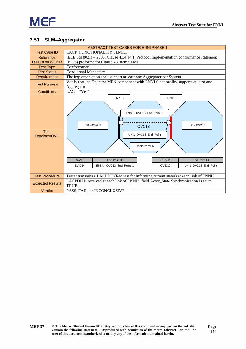
Abstract Test Suite for ENNI
MEF 37 © The Metro Ethernet Forum 2012. Any reproduction of this document, or any portion thereof, shall
contain the following statement: "Reproduced with permission of the Metro Ethernet Forum." No
user of this document is authorized to modify any of the information contained herein.
Page
144
7.51 SLM–Aggregator
ABSTRACT TEST CASES FOR ENNI PHASE 1
Test Case ID LACP_FUNCTIONALITY.SLM1.1
Reference Document Source
IEEE Std 802.3 – 2005, Clause 43.4.14.1, Protocol implementation conformance statement
(PICS) proforma for Clause 43, Item SLM1
Test Type Conformance
Test Status Conditional Mandatory
Requirement The implementation shall support at least one Aggregator per System
Test Purpose Verify that the Operator MEN component with ENNI functionality supports at least one
Aggregator.
Conditions LAG = "Yes"
Test Topology/OVC
Test Procedure Tester transmits a LACPDU (Request for informing current states) at each link of ENNI3
Expected Results LACPDU is received at each link of ENNI3: field Actor_State.Synchronization is set to
TRUE.
Verdict PASS, FAIL, or INCONCLUSIVE
Test System
Operator MEN
S-VID End Point ID
SVID34 ENNI3_OVC13_End_Point_1
CE-VID End Point ID
CVID10 UNI1_OVC13_End_Point
UNI1
Test System
ENNI3
ENNI3_OVC13_End_Point_1
UNI1_OVC13_End_Point
OVC13

Abstract Test Suite for ENNI
MEF 37 © The Metro Ethernet Forum 2012. Any reproduction of this document, or any portion thereof, shall
contain the following statement: "Reproduced with permission of the Metro Ethernet Forum." No
user of this document is authorized to modify any of the information contained herein.
Page
145
7.52 SLM–Port Key
ABSTRACT TEST CASES FOR ENNI PHASE 1
Test Case ID LACP_FUNCTIONALITY.SLM2.1
Reference Document Source
IEEE Std 802.3 – 2005, Clause 43.4.14.1, Protocol implementation conformance statement
(PICS) proforma for Clause 43, Item SLM2
Test Type Conformance
Test Status Conditional Mandatory
Requirement
Each Port shall be assigned an operational Key (43.3.5). Ports that can aggregate together are
assigned the same operational Key as the other ports with which they can aggregate; ports that
cannot aggregate with any other port are allocated unique operational Keys.
Test Purpose Verify that the Operator MEN component with ENNI functionality assigns each port an
operational Key.
Conditions LAG = "Yes"
Test Topology/OVC
Test Procedure Tester transmits a LACPDU (Request for informing current states) at each link of ENNI3
Expected Results LACPDU is received at each link of ENNI3: field Actor_Key is present (value as default
configured)
Verdict PASS, FAIL, or INCONCLUSIVE
Test System
Operator MEN
S-VID End Point ID
SVID34 ENNI3_OVC13_End_Point_1
CE-VID End Point ID
CVID10 UNI1_OVC13_End_Point
UNI1
Test System
ENNI3
ENNI3_OVC13_End_Point_1
UNI1_OVC13_End_Point
OVC13

Abstract Test Suite for ENNI
MEF 37 © The Metro Ethernet Forum 2012. Any reproduction of this document, or any portion thereof, shall
contain the following statement: "Reproduced with permission of the Metro Ethernet Forum." No
user of this document is authorized to modify any of the information contained herein.
Page
146
7.53 SLM–Keys same for Aggregator
ABSTRACT TEST CASES FOR ENNI PHASE 1
Test Case ID LACP_FUNCTIONALITY.SLM5.2
Reference Document Source
IEEE Std 802.3 – 2005, Clause 43.4.14.1, Protocol implementation conformance statement
(PICS) proforma for Clause 43, Item SLM5
Test Type Conformance
Test Status Conditional Mandatory
Requirement A Port shall only select an Aggregator that has the same operational Key assignment as its
own operational Key
Test Purpose Verify that the Operator MEN component with ENNI functionality, when a port has the same
Key value as a Aggregator, attaches it to the Aggregator.
Conditions LAG = "Yes"
Test Topology/OVC
Test Procedure Tester transmits a LACPDU (Request for informing current states) at each link of ENNI3
Expected Results LACPDUs are received at ENNI3: all frames with field Actor_State.Synchronization set to
TRUE have the same value of the field Actor_Key.
Verdict PASS, FAIL, or INCONCLUSIVE
Test System
Operator MEN
S-VID End Point ID
SVID34 ENNI3_OVC13_End_Point_1
CE-VID End Point ID
CVID10 UNI1_OVC13_End_Point
UNI1
Test System
ENNI3
ENNI3_OVC13_End_Point_1
UNI1_OVC13_End_Point
OVC13

Abstract Test Suite for ENNI
MEF 37 © The Metro Ethernet Forum 2012. Any reproduction of this document, or any portion thereof, shall
contain the following statement: "Reproduced with permission of the Metro Ethernet Forum." No
user of this document is authorized to modify any of the information contained herein.
Page
147
7.54 SLM–Keys same for LAG
ABSTRACT TEST CASES FOR ENNI PHASE 1
Test Case ID LACP_FUNCTIONALITY.SLM6.1
Reference Document Source
IEEE Std 802.3 – 2005, Clause 43.4.14.1, Protocol implementation conformance statement
(PICS) proforma for Clause 43, Item SLM6
Test Type Conformance
Test Status Conditional Mandatory
Requirement
Subject to the exception stated in item g), ports that are members of the same Link
Aggregation Group (i.e., two or more ports that have the same Actor_System_ID, Actor_Key,
Partner_System ID, and Partner Key, and that are not required to be Individual) shall select
the same Aggregator.
Test Purpose Verify that the Operator MEN component with ENNI functionality, when links have the same
LAG ID value, attaches them to the same Aggregator.
Conditions LAG = "Yes"
Test Topology/OVC
Test Procedure
Tester transmits a LACPDU (Request for detaching) at the link of ENNI3 configured as
Active.
Tester transmits a LACPDU (Request for informing current states) at each link of ENNI3
Expected Results
LACPDUs are received at ENNI3: all frames with field Actor_State.Synchronization set to
TRUE have identical values in the fields Actor_System_Priority, Actor_System, Actor_Key,
Partner_System_Priority, Partner_System and Partner_Key4
Verdict PASS, FAIL, or INCONCLUSIVE
4 These six values comprise the LAG Identity, as defined in [802.3 – 2005], section 43.3.6.
Test System
Operator MEN
S-VID End Point ID
SVID34 ENNI3_OVC13_End_Point_1
CE-VID End Point ID
CVID10 UNI1_OVC13_End_Point
UNI1
Test System
ENNI3
ENNI3_OVC13_End_Point_1
UNI1_OVC13_End_Point
OVC13

Abstract Test Suite for ENNI
MEF 37 © The Metro Ethernet Forum 2012. Any reproduction of this document, or any portion thereof, shall
contain the following statement: "Reproduced with permission of the Metro Ethernet Forum." No
user of this document is authorized to modify any of the information contained herein.
Page
148
7.55 SLM–Not select the same Aggregator
ABSTRACT TEST CASES FOR ENNI PHASE 1
Test Case ID LACP_FUNCTIONALITY.SLM9.1
Reference Document Source
IEEE Std 802.3 – 2005, Clause 43.4.14.1, Protocol implementation conformance statement
(PICS) proforma for Clause 43, Item SLM9
Test Type Conformance
Test Status Conditional Mandatory
Requirement Any port that is Aggregateable shall not select an Aggregator to which an Individual port is
already attached.
Test Purpose Verify that the Operator MEN component with ENNI functionality when an Individual port is
attached to an Aggregator with, doesn’t select this Aggregator for an Aggregateable port.
Conditions LAG = "Yes"
Test Topology/OVC
Test Procedure
Tester transmits a LACPDU (Request for being Individual) at the link of ENNI3 configured as
Active.
Tester transmits a LACPDU (Request for informing current states)at each link of ENNI3
Expected Results
LACPDU is received at the link of ENNI3 configured as Active: field
Partner_State.LACP_Aggregation is set to FALSE, field Actor_State.Synchronization is set to
FALSE.
LACPDU is received at the link of ENNI3 configured as Standby: field
Partner_State.LACP_Aggregation is set to TRUE, field Actor_State.Synchronization is set to
TRUE.
Verdict PASS, FAIL, or INCONCLUSIVE
Test System
Operator MEN
S-VID End Point ID
SVID34 ENNI3_OVC13_End_Point_1
CE-VID End Point ID
CVID10 UNI1_OVC13_End_Point
UNI1
Test System
ENNI3
ENNI3_OVC13_End_Point_1
UNI1_OVC13_End_Point
OVC13

Abstract Test Suite for ENNI
MEF 37 © The Metro Ethernet Forum 2012. Any reproduction of this document, or any portion thereof, shall
contain the following statement: "Reproduced with permission of the Metro Ethernet Forum." No
user of this document is authorized to modify any of the information contained herein.
Page
149
7.56 PM–SLOW to FAST periodic
ABSTRACT TEST CASES FOR ENNI PHASE 1
Test Case ID TIMERS.PM1.3
Reference Document Source
IEEE Std 802.3 – 2005, Clause 43.4.13, Protocol implementation conformance statement
(PICS) proforma for Clause 43, Item PM1
Test Type Conformance
Test Status Conditional Mandatory
Requirement Periodic Transmission machine as defined in Figure 43–11 and associated parameters
Test Purpose
Verify that the Operator MEN component with ENNI functionality, on receipt of a LACPDU
carrying Actor_State.LACP_Timeout=Short at each link on the protected ENNI, enters
FAST_PERIODIC.
Conditions LAG = "Yes"
Test Topology/OVC
Test Procedure Tester transmits a LACPDU (Request for Fast Mode) at each link of ENNI3
Tester listens for up to (4 x Fast_Periodic_Time) seconds at ENNI3
Expected Results At least two LACPDUs are received at each link of ENNI3: the arrival timestamp difference
between two consecutive frames received at the same link equals Fast_Periodic_Time.
Verdict PASS, FAIL, or INCONCLUSIVE
Test System
Operator MEN
S-VID End Point ID
SVID34 ENNI3_OVC13_End_Point_1
CE-VID End Point ID
CVID10 UNI1_OVC13_End_Point
UNI1
Test System
ENNI3
ENNI3_OVC13_End_Point_1
UNI1_OVC13_End_Point
OVC13

Abstract Test Suite for ENNI
MEF 37 © The Metro Ethernet Forum 2012. Any reproduction of this document, or any portion thereof, shall
contain the following statement: "Reproduced with permission of the Metro Ethernet Forum." No
user of this document is authorized to modify any of the information contained herein.
Page
150
7.57 PM–FAST to SLOW periodic
ABSTRACT TEST CASES FOR ENNI PHASE 1
Test Case ID TIMERS.PM1.4
Reference Document Source
IEEE Std 802.3 – 2005, Clause 43.4.13, Protocol implementation conformance statement
(PICS) proforma for Clause 43, Item PM1
Test Type Conformance
Test Status Conditional Mandatory
Requirement Periodic Transmission machine as defined in Figure 43–11 and associated parameters
Test Purpose
Verify that the Operator MEN component with ENNI functionality, on receipt of a LACPDU
carrying Actor_State.LACP_Timeout=Long at each link on the protected ENNI, enters
SLOW_PERIODIC.
Conditions LAG = "Yes"
Test Topology/OVC
Test Procedure Tester transmits a LACPDU (Default Configuration) at each link of ENNI3
Tester listens for up to.(4 x Slow_Periodic_Time) seconds at ENNI3
Expected Results At least two LACPDUs are received at each link of ENNI3: the arrival timestamp difference
between two consecutive frames received at the same link equals Slow_Periodic_Time.
Verdict PASS, FAIL, or INCONCLUSIVE
Test System
Operator MEN
S-VID End Point ID
SVID34 ENNI3_OVC13_End_Point_1
CE-VID End Point ID
CVID10 UNI1_OVC13_End_Point
UNI1
Test System
ENNI3
ENNI3_OVC13_End_Point_1
UNI1_OVC13_End_Point
OVC13

Abstract Test Suite for ENNI
MEF 37 © The Metro Ethernet Forum 2012. Any reproduction of this document, or any portion thereof, shall
contain the following statement: "Reproduced with permission of the Metro Ethernet Forum." No
user of this document is authorized to modify any of the information contained herein.
Page
151
7.58 RM–Current_While_timer expired
ABSTRACT TEST CASES FOR ENNI PHASE 1
Test Case ID TIMERS.RM1
Reference Document Source
IEEE Std 802.3 – 2005, Clause 43.4.12, Protocol implementation conformance statement
(PICS) proforma for Clause 43, Item RM1
Test Type Conformance
Test Status Conditional Mandatory
Requirement Receive machine as defined in Figure 43–10 and associated parameters
Test Purpose
Verify that the Operator MEN component with ENNI functionality, after current_while_timer
expired at CURRENT state and expired again at EXPIRED state, enters FAST_PERIODIC
state.
Conditions LAG = "Yes"
Test Topology/OVC
Test Procedure
Tester transmits a LACPDU (Default Configuration) at each link of ENNI3.
Tester listens for up to (Long_Timeout_Time + LACP process time + LACPDU listen time +
Fast_Periodic_time)
Expected Results At least one LACPDU is received at each link of ENNI3
Verdict PASS, FAIL, or INCONCLUSIVE
Test System
Operator MEN
S-VID End Point ID
SVID34 ENNI3_OVC13_End_Point_1
CE-VID End Point ID
CVID10 UNI1_OVC13_End_Point
UNI1
Test System
ENNI3
ENNI3_OVC13_End_Point_1
UNI1_OVC13_End_Point
OVC13
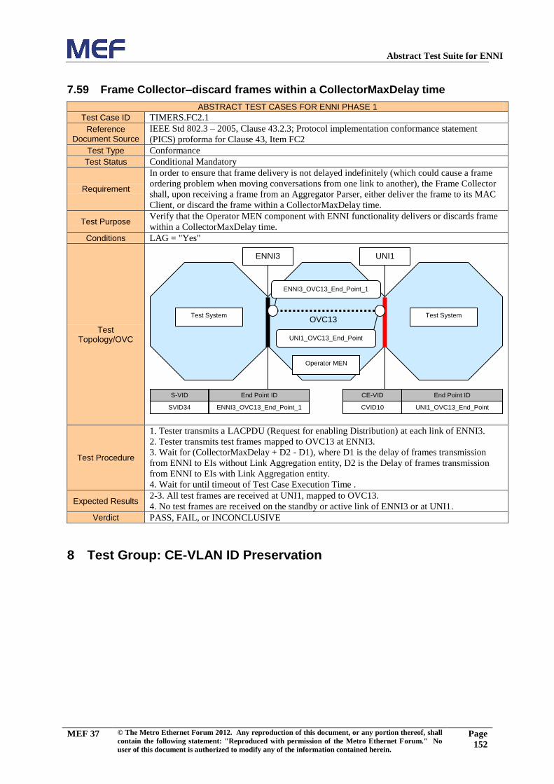
Abstract Test Suite for ENNI
MEF 37 © The Metro Ethernet Forum 2012. Any reproduction of this document, or any portion thereof, shall
contain the following statement: "Reproduced with permission of the Metro Ethernet Forum." No
user of this document is authorized to modify any of the information contained herein.
Page
152
7.59 Frame Collector–discard frames within a CollectorMaxDelay time
ABSTRACT TEST CASES FOR ENNI PHASE 1
Test Case ID TIMERS.FC2.1
Reference Document Source
IEEE Std 802.3 – 2005, Clause 43.2.3; Protocol implementation conformance statement
(PICS) proforma for Clause 43, Item FC2
Test Type Conformance
Test Status Conditional Mandatory
Requirement
In order to ensure that frame delivery is not delayed indefinitely (which could cause a frame
ordering problem when moving conversations from one link to another), the Frame Collector
shall, upon receiving a frame from an Aggregator Parser, either deliver the frame to its MAC
Client, or discard the frame within a CollectorMaxDelay time.
Test Purpose Verify that the Operator MEN component with ENNI functionality delivers or discards frame
within a CollectorMaxDelay time.
Conditions LAG = "Yes"
Test Topology/OVC
Test Procedure
1. Tester transmits a LACPDU (Request for enabling Distribution) at each link of ENNI3.
2. Tester transmits test frames mapped to OVC13 at ENNI3.
3. Wait for (CollectorMaxDelay + D2 - D1), where D1 is the delay of frames transmission
from ENNI to EIs without Link Aggregation entity, D2 is the Delay of frames transmission
from ENNI to EIs with Link Aggregation entity.
4. Wait for until timeout of Test Case Execution Time .
Expected Results 2-3. All test frames are received at UNI1, mapped to OVC13.
4. No test frames are received on the standby or active link of ENNI3 or at UNI1.
Verdict PASS, FAIL, or INCONCLUSIVE
8 Test Group: CE-VLAN ID Preservation
Test System
Operator MEN
S-VID End Point ID
SVID34 ENNI3_OVC13_End_Point_1
CE-VID End Point ID
CVID10 UNI1_OVC13_End_Point
UNI1
Test System
ENNI3
ENNI3_OVC13_End_Point_1
UNI1_OVC13_End_Point
OVC13

Abstract Test Suite for ENNI
MEF 37 © The Metro Ethernet Forum 2012. Any reproduction of this document, or any portion thereof, shall
contain the following statement: "Reproduced with permission of the Metro Ethernet Forum." No
user of this document is authorized to modify any of the information contained herein.
Page
153
8.1 CE-VLAN ID Preservation for Untagged Service Frames – All OVC UNI’s
CE-VLAN IDs Map to the OVC
ABSTRACT TEST CASES FOR ENNI PHASE 1
Test Case ID OVC_ATTRIBUTES.R35.1
Reference Document Source
MEF 26, R35
Test Status Conditional Mandatory
Requirement
When an OVC has the CE-VLAN ID Preservation attribute with a value of Yes and all of the
UNIs with an OVC End Point associated by the OVC are such that all CE-VLAN IDs map to
the OVC End Point (see Section 7.5.2 of [MEF 26]), then the relationship between the format
of the frame at the ingress External Interface and the corresponding frame at the egress
External Interface MUST be as specified in Table 5 of [MEF 26].
Test Purpose
Verify that CE-VLAN ID is preserved for untagged Service Frames if CE-VLAN ID
Preservation attribute has a value of Yes for that OVC and all OVC UNI’s CE-VLAN IDs
map to that OVC. (Row 1 and 2 of Table 5 of [MEF 26])
Conditions
CE-VLAN ID Preservation = "Yes" ,
All OVC UNI’s CE-VLAN IDs map to the OVC = "Yes",
Number of UNI OVCEnd Points > 2
Test Topology/OVC
Test Procedure Tester transmits untagged broadcast test frames mapped to OVC5 at UNI3
Expected Results All test frames are received at UNI4; frames are untagged, preserving the CE-VLAN ID.
All test frames are received at ENNI1 S-tagged only, preserving the CE-VLAN ID.
Verdict PASS, FAIL, or INCONCLUSIVE
Test System
Operator MEN
Test System
ENNI1
Test System
UNI4
CE-VID End Point ID
All UNI3_OVC5_End_Point
UNI3
S-VID End Point ID
SVID7 ENNI1_OVC5_End_Point_1
CE-VID End Point ID
All UNI4_OVC5_End_Point
UNI4_OVC5_End_Point
UNI3_OVC5_End_Point
ENNI1_OVC5_End_Point_1
OVC5
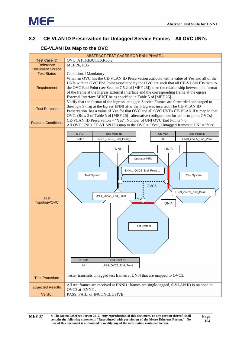
Abstract Test Suite for ENNI
MEF 37 © The Metro Ethernet Forum 2012. Any reproduction of this document, or any portion thereof, shall
contain the following statement: "Reproduced with permission of the Metro Ethernet Forum." No
user of this document is authorized to modify any of the information contained herein.
Page
154
8.2 CE-VLAN ID Preservation for Untagged Service Frames – All OVC UNI’s
CE-VLAN IDs Map to the OVC
ABSTRACT TEST CASES FOR ENNI PHASE 1
Test Case ID OVC_ATTRIBUTES.R35.2
Reference Document Source
MEF 26, R35
Test Status Conditional Mandatory
Requirement
When an OVC has the CE-VLAN ID Preservation attribute with a value of Yes and all of the
UNIs with an OVC End Point associated by the OVC are such that all CE-VLAN IDs map to
the OVC End Point (see Section 7.5.2 of [MEF 26]), then the relationship between the format
of the frame at the ingress External Interface and the corresponding frame at the egress
External Interface MUST be as specified in Table 5 of [MEF 26].
Test Purpose
Verify that the format of the ingress untagged Service Frames are forwarded unchanged to
thesingle S-Tag at the Egress ENNI after the S tag was inserted. The CE-VLAN ID
Preservation has a value of Yes for that OVC and all OVC UNI’s CE-VLAN IDs map to that
OVC. (Row 2 of Table 5 of [MEF 26]– alternative configuration for point-to-point OVCs)
FeaturesConditions CE-VLAN ID Preservation = "Yes", Number of UNI OVC End Points > 0,
All OVC UNI’s CE-VLAN IDs map to the OVC = "Yes", Untagged frames at UNI = "Yes"
Test Topology/OVC
Test Procedure Tester transmits untagged test frames at UNI4 that are mapped to OVC5.
Expected Results All test frames are received at ENNI1: frames are single-tagged, S-VLAN ID is mapped to
OVC5 at ENNI1.
Verdict PASS, FAIL, or INCONCLUSIVE
Test System
Operator MEN
Test System
ENNI1
Test System
UNI4
CE-VID End Point ID
All UNI3_OVC5_End_Point
UNI3
S-VID End Point ID
SVID7 ENNI1_OVC5_End_Point_1
CE-VID End Point ID
All UNI4_OVC5_End_Point
UNI4_OVC5_End_Point
UNI3_OVC5_End_Point
ENNI1_OVC5_End_Point_1
OVC5

Abstract Test Suite for ENNI
MEF 37 © The Metro Ethernet Forum 2012. Any reproduction of this document, or any portion thereof, shall
contain the following statement: "Reproduced with permission of the Metro Ethernet Forum." No
user of this document is authorized to modify any of the information contained herein.
Page
155
8.3 CE-VLAN ID Preservation for C-tagged Service Frames – All OVC UNI’s
CE-VLAN IDs Map to the OVC
ABSTRACT TEST CASES FOR ENNI PHASE 1
Test Case ID OVC_ATTRIBUTES.R35.3
Reference Document Source
MEF 26, R35
Test Status Conditional Mandatory
Requirement
When an OVC has the CE-VLAN ID Preservation attribute with a value of Yes and all of the
UNIs with an OVC End Point associated by the OVC are such that all CE-VLAN IDs map to
the OVC End Point (see Section 7.5.2 of [MEF 26]), then the relationship between the format
of the frame at the ingress External Interface and the corresponding frame at the egress
External Interface MUST be as specified in Table 5 of [MEF 26].
Test Purpose
Verify that CE-VLAN ID is preserved for C-tagged Service Frames if CE-VLAN ID
Preservation attribute has a value of Yes for that OVC and all OVC UNI’s CE-VLAN IDs
map to that OVC.
(Rows 3 and 4 of Table 5 of [MEF 26])
Conditions CE-VLAN ID Preservation = "Yes", All OVC UNI’s CE-VLAN IDs map to the OVC = "Yes"
Test Topology/OVC
Test Procedure Tester transmits C-Tag test frames at UNI3 that are mapped to OVC5.
Expected Results
All test frames are received at UNI4: frames carry a C-Tag preserving the original CE-VLAN
ID.
All test frames are received at ENNI1 double-tagged, preserving the original CE-VLAN ID.
Verdict PASS, FAIL, or INCONCLUSIVE
Test System
Operator MEN
Test System
ENNI1
Test System
UNI4
CE-VID End Point ID
All UNI3_OVC5_End_Point
UNI3
S-VID End Point ID
SVID7 ENNI1_OVC5_End_Point_1
CE-VID End Point ID
All UNI4_OVC5_End_Point
UNI4_OVC5_End_Point
UNI3_OVC5_End_Point
ENNI1_OVC5_End_Point_1
OVC5

Abstract Test Suite for ENNI
MEF 37 © The Metro Ethernet Forum 2012. Any reproduction of this document, or any portion thereof, shall
contain the following statement: "Reproduced with permission of the Metro Ethernet Forum." No
user of this document is authorized to modify any of the information contained herein.
Page
156
8.4 CE-VLAN ID Preservation for C-tagged Service Frames –All OVC UNI’s
CE-VLAN IDs Map to the OVC
ABSTRACT TEST CASES FOR ENNI PHASE 1
Test Case ID OVC_ATTRIBUTES.R35.4
Reference Document Source
MEF 26, R35
Test Status Conditional Mandatory
Requirement
When an OVC has the CE-VLAN ID Preservation attribute with a value of Yes and all of
the UNIs with an OVC End Point associated by the OVC are such that all CE-VLAN IDs
map to the OVC End Point (see Section 7.5.2 of [MEF 26]), then the relationship between
the format of the frame at the ingress External Interface and the corresponding frame at the
egress External Interface MUST be as specified in Table 5 of [MEF 26].
Test Purpose
Verify that CE-VLAN ID is preserved for C-tagged Service frames if CE-VLAN ID
Preservation attribute has a value of Yes for that OVC and all OVC UNI’s CE-VLAN IDs
map to that OVC.
(Row 4 of Table 5 of [MEF 26], alternative test case for point-to-point OVCs)
FeaturesConditions CE-VLAN ID Preservation = "Yes", Number of UNI OVC End Points > 0,
All OVC UNI’s CE-VLAN IDs map to the OVC = "Yes", Tagged frames at UNI = "Yes"
Test Topology/OVC
Test Procedure Tester transmits C-tagged test frames at UNI1 that are mapped to OVC31.
Expected Results All test frames are received at ENNI1: frames are double-tagged, with the original CE-
VLAN ID preserved, S-VLAN ID is mapped to OVC5 at ENNI1.
Verdict PASS, FAIL, or INCONCLUSIVE
Test System
Operator MEN
S-VID End Point ID
SVID37 ENNI1_OVC31_End_Point_1
CE-VID End Point ID
CVID27 UNI1_OVC31_End_Point
UNI1
Test System
ENNI1
ENNI1_OVC31_End_Point_1
UNI1_OVC31_End_Point
OVC31

Abstract Test Suite for ENNI
MEF 37 © The Metro Ethernet Forum 2012. Any reproduction of this document, or any portion thereof, shall
contain the following statement: "Reproduced with permission of the Metro Ethernet Forum." No
user of this document is authorized to modify any of the information contained herein.
Page
157
8.5 CE-VLAN ID Preservation for ENNI Frames With S- and C-tag – All OVC
UNI’s CE-VLAN IDs Map to the OVC
ABSTRACT TEST CASES FOR ENNI PHASE 1
Test Case ID OVC_ATTRIBUTES.R35.5
Reference Document Source
MEF 26, R35
Test Status Conditional Mandatory
Requirement
When an OVC has the CE-VLAN ID Preservation attribute with a value of Yes and all of the
UNIs with an OVC End Point associated by the OVC are such that all CE-VLAN IDs map to
the OVC End Point (see Section 7.5.2 of [MEF 26]), then the relationship between the format
of the frame at the ingress External Interface and the corresponding frame at the egress
External Interface MUST be as specified in Table 5 of [MEF 26].
Test Purpose
Verify that the ENNI Frames with S- and C-tags are forwarded to the UNI after the S-Tag was
deleted. The CE-VLAN ID Preservation attribute has a value of Yes for that OVC and all
OVC UNI’s CE-VLAN IDs map to that OVC.
(Row 5 of Table 5 of [MEF 26])
Conditions CE-VLAN ID Preservation = "Yes",
All OVC UNI’s CE-VLAN IDs map to the OVC = "Yes", Tagged frames at UNI = "Yes"
Test Topology/OVC
Test Procedure Tester transmits double-tagged test frames mapped to OVC31 at ENNI1, with C-VLAN ID set
to CVID27.
Expected Results All test frames are received at their destination UNIs: Frames are C-tagged with the original
C-VLAN ID preserved.
Verdict PASS, FAIL, or INCONCLUSIVE
Test System
Operator MEN
S-VID End Point ID
SVID37 ENNI1_OVC31_End_Point_1
CE-VID End Point ID
CVID27 UNI1_OVC31_End_Point
UNI1
Test System
ENNI1
ENNI1_OVC31_End_Point_1
UNI1_OVC31_End_Point
OVC31

Abstract Test Suite for ENNI
MEF 37 © The Metro Ethernet Forum 2012. Any reproduction of this document, or any portion thereof, shall
contain the following statement: "Reproduced with permission of the Metro Ethernet Forum." No
user of this document is authorized to modify any of the information contained herein.
Page
158
8.6 CE-VLAN ID Preservation for ENNI Frames With S-Tag Only – All OVC
UNI’s CE-VLAN IDs Map to the OVC
ABSTRACT TEST CASES FOR ENNI PHASE 1
Test Case ID OVC_ATTRIBUTES.R35.6
Reference Document Source
MEF 26, R35
Test Status Conditional Mandatory
Requirement
When an OVC has the CE-VLAN ID Preservation attribute with a value of Yes and all of the
UNIs with an OVC End Point associated by the OVC are such that all CE-VLAN IDs map to
the OVC End Point (see Section 7.5.2 of [MEF 26]), then the relationship between the format
of the frame at the ingress External Interface and the corresponding frame at the egress
External Interface MUST be as specified in Table 5 of [MEF 26].
Test Purpose
Verify that the ENNI Frames with S-Tag only are forwarded unchanged to the UNI after the
S-Tag was deleted. The CE-VLAN ID Preservation attribute has a value of Yesfor that OVC
and all OVC UNI’s CE-VLAN IDs map to that OVC.
(Row 6 of Table 5 of [MEF 26])
Conditions CE-VLAN ID Preservation = "Yes"
All OVC UNI’s CE-VLAN IDs map to the OVC = "Yes"
Test Topology/OVC
Test Procedure Tester transmits single S-tagged test frames that are mapped to OVC31 at ENNI1.
Expected Results All test frames are received at their destination UNIs: frames are untagged.
Verdict PASS, FAIL, or INCONCLUSIVE
Test System
Operator MEN
S-VID End Point ID
SVID37 ENNI1_OVC31_End_Point_1
CE-VID End Point ID
CVID27 UNI1_OVC31_End_Point
UNI1
Test System
ENNI1
ENNI1_OVC31_End_Point_1
UNI1_OVC31_End_Point
OVC31

Abstract Test Suite for ENNI
MEF 37 © The Metro Ethernet Forum 2012. Any reproduction of this document, or any portion thereof, shall
contain the following statement: "Reproduced with permission of the Metro Ethernet Forum." No
user of this document is authorized to modify any of the information contained herein.
Page
159
8.7 CE-VLAN ID Preservation for ENNI Frames With S- and C-tag – All OVC
UNI’s CE-VLAN IDs Map to the OVC
ABSTRACT TEST CASES FOR ENNI PHASE 1
Test Case ID OVC_ATTRIBUTES.R35.7
Reference Document Source
MEF 26, R35
Test Status Conditional Mandatory
Requirement
When an OVC has the CE-VLAN ID Preservation attribute with a value of Yes and all of the
UNIs with an OVC End Point associated by the OVC are such that all CE-VLAN IDs map to
the OVC End Point (see Section 7.5.2 of [MEF 26]), then the relationship between the format
of the frame at the ingress External Interface and the corresponding frame at the egress
External Interface MUST be as specified in Table 5 of [MEF 26].
Test Purpose
Verify that ENNI Frames with S- and C-Tags are forwarded to another ENNI. The CE-VLAN
ID Preservation attribute has a value of Yes for that OVC and all OVC UNI’s CE-VLAN IDs
map to that OVC.
(Row 7 of Table 5 of [MEF 26])
Conditions CE-VLAN ID Preservation = "Yes", Number of ENNI OVC End Points > 1, All OVC UNI’s
CE-VLAN IDs map to the OVC = "Yes"
Test Topology/OVC
Test Procedure
Tester transmits double-tagged test frames mapped to OVC35 at ENNI1: CE-VLAN ID is set
to to values from CVID1 to CVID30, destination MAC addresses are emulated behind
ENNI2.
Expected Results All test frames are received at ENNI2 or UNI7: ENNI frames are double-tagged, with the
original CE-VLAN ID preserved:
Verdict PASS, FAIL, or INCONCLUSIVE
Test System
Operator MEN
Test System
ENNI1
Test System
UNI7
S-VID End Point ID
SVID45 ENNI2_OVC35_End_Point_1
ENNI2
S-VID End Point ID
SVID46 ENNI1_OVC35_End_Point_1
CE-VID End Point ID
All UNI7_OVC35_End_Point
UNI7_OVC35_End_Point
ENNI2_OVC35_End_Point_1
ENNI1_OVC35_End_Point_1
OVC35

Abstract Test Suite for ENNI
MEF 37 © The Metro Ethernet Forum 2012. Any reproduction of this document, or any portion thereof, shall
contain the following statement: "Reproduced with permission of the Metro Ethernet Forum." No
user of this document is authorized to modify any of the information contained herein.
Page
160
8.8 CE-VLAN ID Preservation for ENNI frames With S-tag Only – All OVC
UNI’s CE-VLAN IDs Map to the OVC
ABSTRACT TEST CASES FOR ENNI PHASE 1
Test Case ID OVC_ATTRIBUTES.R35.8
Reference Document Source
MEF 26, R35
Test Status Conditional Mandatory
Requirement
When an OVC has the CE-VLAN ID Preservation attribute with a value of Yes and all of the
UNIs with an OVC End Point associated by the OVC are such that all CE-VLAN IDs map to
the OVC End Point (see Section 7.5.2 of [MEF 26]), then the relationship between the format
of the frame at the ingress External Interface and the corresponding frame at the egress
External Interface MUST be as specified in Table 5 of [MEF 26].
Test Purpose
Verify that the ENNI frames with S-Tag only are forwarded unchanged to the destination
ENNI except the S tag, which may change. The CE-VLAN ID Preservation attribute has a
value of Yes for that OVC and all OVC UNI’s CE-VLAN IDs map to that OVC.
(Row 8 of Table 5 of [MEF 26])
Conditions CE-VLAN ID Preservation = "Yes", Number of ENNI OVC End Points > 1, All OVC UNI’s
CE-VLAN IDs map to the OVC = "Yes", Untagged frames at UNI = "Yes"
Test Topology/OVC
Test Procedure Tester transmits single S-tagged test frames mapped to OVC35 at ENNI1: destination MAC
addresses are emulated behind ENNI2.
Expected Results All test frames are received at ENNI2 or UNI7: ENNI frames are single-tagged.
Verdict PASS, FAIL, or INCONCLUSIVE
Test System
Operator MEN
Test System
ENNI1
Test System
UNI7
S-VID End Point ID
SVID45 ENNI2_OVC35_End_Point_1
ENNI2
S-VID End Point ID
SVID46 ENNI1_OVC35_End_Point_1
CE-VID End Point ID
All UNI7_OVC35_End_Point
UNI7_OVC35_End_Point
ENNI2_OVC35_End_Point_1
ENNI1_OVC35_End_Point_1
OVC35

Abstract Test Suite for ENNI
MEF 37 © The Metro Ethernet Forum 2012. Any reproduction of this document, or any portion thereof, shall
contain the following statement: "Reproduced with permission of the Metro Ethernet Forum." No
user of this document is authorized to modify any of the information contained herein.
Page
161
8.9 CE-VLAN ID Preservation for C-tagged Service Frames – Not All OVC
UNI’s CE-VLAN IDs Map to the OVC
ABSTRACT TEST CASES FOR ENNI PHASE 1
Test Case ID OVC_ATTRIBUTES.R36.1
Reference Document Source
MEF 26, R36
Test Status Conditional Mandatory
Requirement
When an OVC has the CE-VLAN ID Preservation attribute with a value of Yes and not all of
the UNIs with an OVC End Point associated by the OVC are such that all CE-VLAN IDs map
to the OVC End Point (see Section 7.5.2 of [MEF 26]), then the relationships between the
format of the frame at the ingress External Interface and the corresponding frame at the egress
External Interface MUST be as specified in Table 6 of [MEF 26].
Test Purpose
Verify that CE-VLAN ID is preserved for Service Frames if CE-VLAN ID Preservation
attribute has a value of Yes for that OVC and not all OVC UNI’s CE-VLAN IDs map to that
OVC.
(Rows 1 and 2 of Table 6 of [MEF 26])
Conditions CE-VLAN ID Preservation = "Yes", Number of UNI OVC End Points > 1, All OVC UNI’s
CE-VLAN IDs map to the OVC = "No", Tagged frames at UNI = "Yes"
Test Topology/OVC
Test Procedure Tester transmits C-tagged broadcast test frames at UNI1 that are mapped to OVC6.
Expected Results All test frames are received at UNI2, preserving the original CE-VLAN ID. All test frames are
received at ENNI1 with the original CE-VLAN ID preserved.
Verdict PASS, FAIL, or INCONCLUSIVE
Test System
Operator MEN
Test System
ENNI1
Test System
UNI2
CE-VID End Point ID
CVID3 UNI1_OVC6_End_Point
CVID4 UNI1_OVC6_End_Point
UNI1
S-VID End Point ID
SVID8 ENNI1_OVC6_End_Point_1
CE-VID End Point ID
CVID5 UNI2_OVC6_End_Point
UNI2_OVC6_End_Point
UNI1_OVC6_End_Point
ENNI1_OVC6_End_Point_1
OVC6

Abstract Test Suite for ENNI
MEF 37 © The Metro Ethernet Forum 2012. Any reproduction of this document, or any portion thereof, shall
contain the following statement: "Reproduced with permission of the Metro Ethernet Forum." No
user of this document is authorized to modify any of the information contained herein.
Page
162
8.10 CE-VLAN ID Preservation for C-tagged Service Frames – Not All OVC
UNI’s CE-VLAN IDs Map to the OVC
ABSTRACT TEST CASES FOR ENNI PHASE 1
Test Case ID OVC_ATTRIBUTES.R36.2
Reference Document Source
MEF 26, R36
Test Status Conditional Mandatory
Requirement
When an OVC has the CE-VLAN ID Preservation attribute with a value of Yes and not all of
the UNIs with an OVC End Point associated by the OVC are such that all CE-VLAN IDs map
to the OVC End Point (see Section 7.5.2 of [MEF 26]), then the relationships between the
format of the frame at the ingress External Interface and the corresponding frame at the egress
External Interface MUST be as specified in Table 6 of [MEF 26].
Test Purpose
Verify that CE-VLAN ID is preserved if CE-VLAN ID Preservation attribute has a value of
Yes for that OVC and not all OVC UNI’s CE-VLAN IDs map to that OVC.
(Row 2 of Table 6 of [MEF 26], alternative test case for point-to-point OVCs)
Conditions CE-VLAN ID Preservation = "Yes”, , All OVC UNI’s CE-VLAN IDs map to the OVC =
"No", Tagged frames at UNI = "Yes"
Test Topology/OVC
Test Procedure Tester transmits C-tagged test frames at UNI1
Expected Results All test frames are received at ENNI1: frames are double-tagged, original CE-VLAN ID is
preserved.
Verdict PASS, FAIL, or INCONCLUSIVE
Test System
Operator MEN
S-VID End Point ID
SVID37 ENNI1_OVC31_End_Point_1
CE-VID End Point ID
CVID27 UNI1_OVC31_End_Point
UNI1
Test System
ENNI1
ENNI1_OVC31_End_Point_1
UNI1_OVC31_End_Point
OVC31

Abstract Test Suite for ENNI
MEF 37 © The Metro Ethernet Forum 2012. Any reproduction of this document, or any portion thereof, shall
contain the following statement: "Reproduced with permission of the Metro Ethernet Forum." No
user of this document is authorized to modify any of the information contained herein.
Page
163
8.11 CE-VLAN ID Preservation for ENNI Frames – Not All OVC UNI’s CE-VLAN
IDs Map to the OVC
ABSTRACT TEST CASES FOR ENNI PHASE 1
Test Case ID OVC_ATTRIBUTES.R36.3
Reference Document Source
MEF 26, R36
Test Status Conditional Mandatory
Requirement
When an OVC has the CE-VLAN ID Preservation attribute with a value of Yes and not all of
the UNIs with an OVC End Point associated by the OVC are such that all CE-VLAN IDs map
to the OVC End Point (see Section 7.5.2 of [MEF 26]), then the relationships between the
format of the frame at the ingress External Interface and the corresponding frame at the egress
External Interface MUST be as specified in Table 6 of [MEF 26].
Test Purpose
Verify that the ENNI Frames are forwarded to the UNI after the S-Tag was deleted. The CE-
VLAN ID Preservation attribute has a value of Yes for that OVC and not all OVC UNI’s CE-
VLAN IDs map to that OVC.
(Row 3 of Table 6 of [MEF 26])
Conditions CE-VLAN ID Preservation = "Yes", , All OVC UNI’s CE-VLAN IDs map to the OVC =
"No", Tagged frames at UNI = "Yes"
Test Topology/OVC
Test Procedure Tester transmits double-tagged test frames at ENNI1 that are mapped to OVC31 with CVID
27, destination MAC addresses are emulated behind UNI1.
Expected Results C-Tag test frames are received at UNI1: original CE-VLAN ID is preserved.
Verdict PASS, FAIL, or INCONCLUSIVE
Test System
Operator MEN
S-VID End Point ID
SVID37 ENNI1_OVC31_End_Point_1
CE-VID End Point ID
CVID27 UNI1_OVC31_End_Point
UNI1
Test System
ENNI1
ENNI1_OVC31_End_Point_1
UNI1_OVC31_End_Point
OVC31
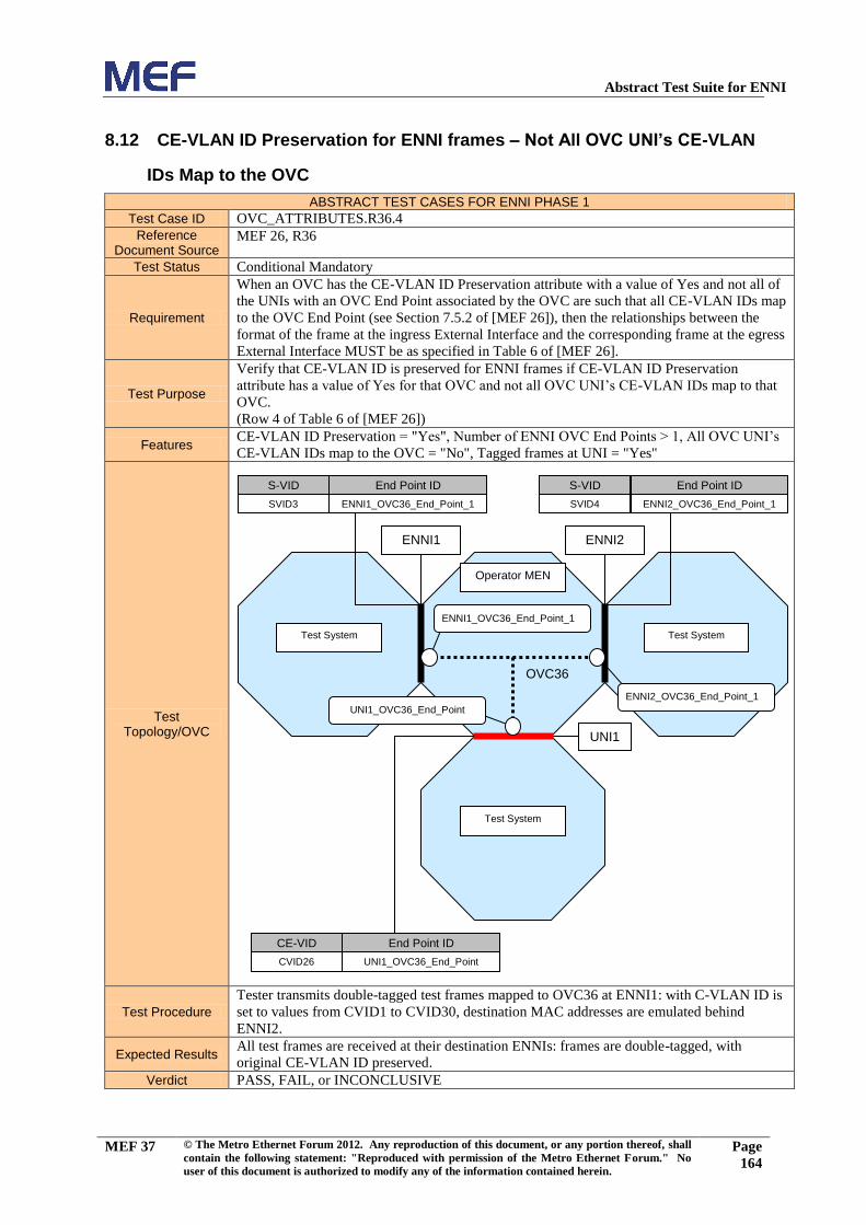
Abstract Test Suite for ENNI
MEF 37 © The Metro Ethernet Forum 2012. Any reproduction of this document, or any portion thereof, shall
contain the following statement: "Reproduced with permission of the Metro Ethernet Forum." No
user of this document is authorized to modify any of the information contained herein.
Page
164
8.12 CE-VLAN ID Preservation for ENNI frames – Not All OVC UNI’s CE-VLAN
IDs Map to the OVC
ABSTRACT TEST CASES FOR ENNI PHASE 1
Test Case ID OVC_ATTRIBUTES.R36.4
Reference Document Source
MEF 26, R36
Test Status Conditional Mandatory
Requirement
When an OVC has the CE-VLAN ID Preservation attribute with a value of Yes and not all of
the UNIs with an OVC End Point associated by the OVC are such that all CE-VLAN IDs map
to the OVC End Point (see Section 7.5.2 of [MEF 26]), then the relationships between the
format of the frame at the ingress External Interface and the corresponding frame at the egress
External Interface MUST be as specified in Table 6 of [MEF 26].
Test Purpose
Verify that CE-VLAN ID is preserved for ENNI frames if CE-VLAN ID Preservation
attribute has a value of Yes for that OVC and not all OVC UNI’s CE-VLAN IDs map to that
OVC.
(Row 4 of Table 6 of [MEF 26])
Features CE-VLAN ID Preservation = "Yes", Number of ENNI OVC End Points > 1, All OVC UNI’s
CE-VLAN IDs map to the OVC = "No", Tagged frames at UNI = "Yes"
Test Topology/OVC
Test Procedure
Tester transmits double-tagged test frames mapped to OVC36 at ENNI1: with C-VLAN ID is
set to values from CVID1 to CVID30, destination MAC addresses are emulated behind
ENNI2.
Expected Results All test frames are received at their destination ENNIs: frames are double-tagged, with
original CE-VLAN ID preserved.
Verdict PASS, FAIL, or INCONCLUSIVE
Test System
Operator MEN
Test System
ENNI1
Test System
UNI1
S-VID End Point ID
SVID4 ENNI2_OVC36_End_Point_1
ENNI2
S-VID End Point ID
SVID3 ENNI1_OVC36_End_Point_1
CE-VID End Point ID
CVID26 UNI1_OVC36_End_Point
UNI1_OVC36_End_Point
ENNI2_OVC36_End_Point_1
ENNI1_OVC36_End_Point_1
OVC36

Abstract Test Suite for ENNI
MEF 37 © The Metro Ethernet Forum 2012. Any reproduction of this document, or any portion thereof, shall
contain the following statement: "Reproduced with permission of the Metro Ethernet Forum." No
user of this document is authorized to modify any of the information contained herein.
Page
165
8.13 CE-VLAN ID Preservation for ENNI frames With C- and S-Tag – OVC
Without UNI End Points
ABSTRACT TEST CASES FOR ENNI PHASE 1
Test Case ID OVC_ATTRIBUTES.R37.1
Reference Document Source
MEF 26, R37
Test Status Conditional Mandatory
Requirement
When an OVC has the CE-VLAN ID Preservation attribute with a value of Yes and none of
the End Points associated by the OVC are at UNIs, then the relationships between the format
of the frame at the ingress ENNI and the corresponding frame at the egress ENNI MUST be as
specified in Table 7 of [MEF 26].
Test Purpose
Verify that CE-VLAN ID is preserved for double-tagged frames of OVC without End Points
at UNIs if CE-VLAN ID Preservation attribute has a value of Yes for that OVC.
(Row 1 of Table 7 of [MEF 26])
Conditions CE-VLAN ID Preservation = "Yes", Number of UNI OVC End Points = 0, Number of ENNIs
> 1
Test Topology/OVC
Test Procedure Tester transmits double-tagged test frames at ENNI1 that are mapped to OVC2.
Expected Results All test frames are received at ENNI2: frames are double-tagged, original CE-VLAN ID is
preserved.
Verdict PASS, FAIL, or INCONCLUSIVE
Operator MEN
S-VID End Point ID
SVID2 ENNI1_OVC2_End_Point_1
S-VID End Point ID
SVID2 ENNI2_OVC2_End_Point_1
Test System
ENNI2
Test System
ENNI1
ENNI1_OVC2_End_Point_1
ENNI2_OVC2_End_Point_1
OVC2
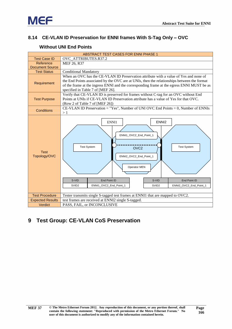
Abstract Test Suite for ENNI
MEF 37 © The Metro Ethernet Forum 2012. Any reproduction of this document, or any portion thereof, shall
contain the following statement: "Reproduced with permission of the Metro Ethernet Forum." No
user of this document is authorized to modify any of the information contained herein.
Page
166
8.14 CE-VLAN ID Preservation for ENNI frames With S-Tag Only – OVC
Without UNI End Points
ABSTRACT TEST CASES FOR ENNI PHASE 1
Test Case ID OVC_ATTRIBUTES.R37.2
Reference Document Source
MEF 26, R37
Test Status Conditional Mandatory
Requirement
When an OVC has the CE-VLAN ID Preservation attribute with a value of Yes and none of
the End Points associated by the OVC are at UNIs, then the relationships between the format
of the frame at the ingress ENNI and the corresponding frame at the egress ENNI MUST be as
specified in Table 7 of [MEF 26].
Test Purpose
Verify that CE-VLAN ID is preserved for frames without C-tag for an OVC without End
Points at UNIs if CE-VLAN ID Preservation attribute has a value of Yes for that OVC.
(Row 2 of Table 7 of [MEF 26])
Conditions CE-VLAN ID Preservation = "Yes", Number of UNI OVC End Points = 0, Number of ENNIs
> 1
Test Topology/OVC
Test Procedure Tester transmits single S-tagged test frames at ENNI1 that are mapped to OVC2.
Expected Results test frames are received at ENNI2 single S-tagged.
Verdict PASS, FAIL, or INCONCLUSIVE
9 Test Group: CE-VLAN CoS Preservation
Operator MEN
S-VID End Point ID
SVID2 ENNI1_OVC2_End_Point_1
S-VID End Point ID
SVID2 ENNI2_OVC2_End_Point_1
Test System
ENNI2
Test System
ENNI1
ENNI1_OVC2_End_Point_1
ENNI2_OVC2_End_Point_1
OVC2

Abstract Test Suite for ENNI
MEF 37 © The Metro Ethernet Forum 2012. Any reproduction of this document, or any portion thereof, shall
contain the following statement: "Reproduced with permission of the Metro Ethernet Forum." No
user of this document is authorized to modify any of the information contained herein.
Page
167
9.1 CE-VLAN CoS Preservation for ENNI Frames
ABSTRACT TEST CASES FOR ENNI PHASE 1
Test Case ID OVC_ATTRIBUTES. R38.1
Reference Document Source
MEF 26, R38
Test Status Conditional Mandatory
Requirement
When an OVC has the CE-VLAN CoS Preservation attribute with a value of Yes the
relationship between the format of the frame at the ingress External Interface and the
corresponding frame at the egress External Interface MUST be as specified in Table 8 of
[MEF 26].
Test Purpose
Verify that the ENNI Frames are forwarded to the UNI with unchanged CE-VLAN CoS field
if CE-VLAN CoS preservation is enabled for that OVC.
(Row 3 of Table 8 of [MEF 26])
Conditions CE-VLAN CoS preservation = "Yes", Tagged frames at UNI = "Yes"
Test Topology/OVC
Test Procedure Tester transmits double-tagged test frames at ENNI1 that are mapped to OVC34 with CE
VLAN CoS set to values from 0 to 7.
Expected Results All test frames are received at UNI1, mapped to OVC34: frames are C-tagged, each CE
VLAN CoS is received unchanged.
Verdict PASS, FAIL, or INCONCLUSIVE
Test System
Operator MEN
S-VID End Point ID
SVID44 ENNI1_OVC34_En
d_Point_1
CE-VID End Point ID
CVID32 UNI1_OVC34_End_
Point
UNI1
Test System
ENNI1
ENNI1_OVC34_End
_Point_1
UNI1_OVC34_En
d_Point
OVC34

Abstract Test Suite for ENNI
MEF 37 © The Metro Ethernet Forum 2012. Any reproduction of this document, or any portion thereof, shall
contain the following statement: "Reproduced with permission of the Metro Ethernet Forum." No
user of this document is authorized to modify any of the information contained herein.
Page
168
9.2 CE-VLAN CoS Preservation for C-tagged Service Frames
ABSTRACT TEST CASES FOR ENNI PHASE 1
Test Case ID OVC_ATTRIBUTES. R38.2
Reference Document Source
MEF 26, R38
Test Status Conditional Mandatory
Requirement
When an OVC has the CE-VLAN CoS Preservation attribute with a value of Yes the
relationship between the format of the frame at the ingress External Interface and the
corresponding frame at the egress External Interface MUST be as specified in Table 8 of
[MEF 26].
Test Purpose
Verify that the Service Frames are forwarded to their destination ENNIs with unchanged CE-
VLAN CoS field if CE-VLAN CoS preservation is enabled for that OVC.
(Row 2 of Table 8 of [MEF 26])
Conditions CE-VLAN CoS preservation = "Yes", , Tagged frames at UNI = "Yes"
Test Topology/OVC
Test Procedure Tester transmits C-tagged test frames at UNI1 that are mapped to OVC34 with CE VLAN
CoS values of 0 to 7.
Expected Results All test frames are received at ENNI1, mapped to OVC34: frames are double-tagged, CE-
VLAN CoS values are unchanged.
Verdict PASS, FAIL, or INCONCLUSIVE
Test System
Operator MEN
S-VID End Point ID
SVID44 ENNI1_OVC34_End_Point_1
CE-VID End Point ID
CVID32 UNI1_OVC34_End_Point
UNI1
Test System
ENNI1
ENNI1_OVC34_End_Point_1
UNI1_OVC34_End_Point
OVC34

Abstract Test Suite for ENNI
MEF 37 © The Metro Ethernet Forum 2012. Any reproduction of this document, or any portion thereof, shall
contain the following statement: "Reproduced with permission of the Metro Ethernet Forum." No
user of this document is authorized to modify any of the information contained herein.
Page
169
9.3 CE-VLAN CoS Preservation for C-Tagged Service Frames to UNI
ABSTRACT TEST CASES FOR ENNI PHASE 1
Test Case ID OVC_ATTRIBUTES. R38.3
Reference Document Source
MEF 26, R38
Test Status Conditional Mandatory
Requirement
When an OVC has the CE-VLAN CoS Preservation attribute with a value of Yes the
relationship between the format of the frame at the ingress External Interface and the
corresponding frame at the egress External Interface MUST be as specified in Table 8 of
[MEF 26].
Test Purpose
Verify that the Service Frames are forwarded to their destination UNIs with unchanged CE-
VLAN CoS field if CE-VLAN CoS preservation is enabled for that OVC.
(Row 1 of Table 8 of [MEF 26])
Conditions CE-VLAN CoS preservation = "Yes", Number of UNI OVC End Points > 1, Tagged frames at
UNI = "Yes"
Test Topology/OVC
Test Procedure Tester transmits C-tagged broadcast test frames at UNI1 that are mapped to OVC6 with CE
VLAN CoS values of 0 to 7.
Expected Results
All test frames are received at UNI2: CE VLAN CoS values are unchanged.
NOTE: Test frames are received at ENNI1. This test is only focused on UNI1 to UNI2
functionality.
Verdict PASS, FAIL, or INCONCLUSIVE
Test System
Operator MEN
Test System
ENNI1
Test System
UNI2
CE-VID End Point ID
CVID3 UNI1_OVC6_End_Point
CVID4 UNI1_OVC6_End_Point
UNI1
S-VID End Point ID
SVID8 ENNI1_OVC6_End_Point_1
CE-VID End Point ID
CVID5 UNI2_OVC6_End_Point
UNI2_OVC6_End_Point
UNI1_OVC6_End_Point
ENNI1_OVC6_End_Point_1
OVC6
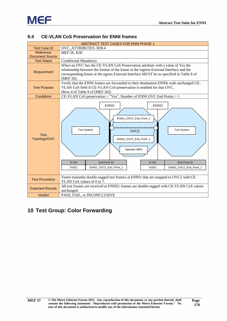
Abstract Test Suite for ENNI
MEF 37 © The Metro Ethernet Forum 2012. Any reproduction of this document, or any portion thereof, shall
contain the following statement: "Reproduced with permission of the Metro Ethernet Forum." No
user of this document is authorized to modify any of the information contained herein.
Page
170
9.4 CE-VLAN CoS Preservation for ENNI frames
ABSTRACT TEST CASES FOR ENNI PHASE 1
Test Case ID OVC_ATTRIBUTES. R38.4
Reference Document Source
MEF 26, R38
Test Status Conditional Mandatory
Requirement
When an OVC has the CE-VLAN CoS Preservation attribute with a value of Yes the
relationship between the format of the frame at the ingress External Interface and the
corresponding frame at the egress External Interface MUST be as specified in Table 8 of
[MEF 26].
Test Purpose
Verify that the ENNI frames are forwarded to their destination ENNIs with unchanged CE-
VLAN CoS field if CE-VLAN CoS preservation is enabled for that OVC.
(Row 4 of Table 8 of [MEF 26])
Conditions CE-VLAN CoS preservation = "Yes", Number of ENNI OVC End Points > 1
Test Topology/OVC
Test Procedure Tester transmits double-tagged test frames at ENNI1 that are mapped to OVC2 with CE
VLAN CoS values of 0 to 7.
Expected Results All test frames are received at ENNI2: frames are double-tagged with CE-VLAN CoS values
unchanged.
Verdict PASS, FAIL, or INCONCLUSIVE
10 Test Group: Color Forwarding
Operator MEN
S-VID End Point ID
SVID2 ENNI1_OVC2_End_Point_1
S-VID End Point ID
SVID2 ENNI2_OVC2_End_Point_1
Test System
ENNI2
Test System
ENNI1
ENNI1_OVC2_End_Point_1
ENNI2_OVC2_End_Point_1
OVC2

Abstract Test Suite for ENNI
MEF 37 © The Metro Ethernet Forum 2012. Any reproduction of this document, or any portion thereof, shall
contain the following statement: "Reproduced with permission of the Metro Ethernet Forum." No
user of this document is authorized to modify any of the information contained herein.
Page
171
10.1 Yellow Color Declaration by UNI Ingress BWP, ENNI Yellow Color
Indication by S-VLAN PCP
ABSTRACT TEST CASES FOR ENNI PHASE 1
Test Case ID COLOR_FORWARDING. R43.1
Reference Document Source
MEF 26, R43
Test Status Conditional Mandatory
Requirement
When the Color Forwarding attribute is Yes for an OVC, each egress ENNI Frame mapped to
an OVC End Point that is associated by the OVC MUST be marked Yellow using one of the
formats specified in Section 7.3.2 of [MEF 26] if the corresponding ingress frame into the
Operator MEN satisfied one or more of the following:
The corresponding ingress frame was a Service Frame that was declared Yellow by
an Ingress Bandwidth Profile and the Service Frame was mapped to an OVC End
Point at the UNI that is associated by the OVC,
The corresponding ingress frame was a Service Frame with a frame header indicating
Yellow as specified in MEF 23 [MEF 23] and the Service Frame was mapped to an
OVC End Point at the UNI that is associated by the OVC,
The corresponding ingress frame was an ENNI Frame that was declared Yellow by
an Ingress Bandwidth Profile and the ENNI Frame was mapped to an OVC End Point
at the ENNI that is associated by the OVC,
The corresponding ingress frame was an ENNI Frame with a frame header indicating
Yellow using one of the formats specified in Section 7.3.2 of [MEF 26] and the
ENNI Frame was mapped to an OVC End Point at the ENNI that is associated by the
OVC.
Test Purpose
Verify that each egress ENNI Frame is marked Yellow, if the following conditions are
fulfilled:
The egress ENNI Frames are mapped to an UNI OVC End Point associated by an
OVC,
The egress ENNI Frames were previously declared Yellow by an Ingress Bandwidth
Profile associated with that OVC at UNI
The Color Forwarding is enabled for that OVC
S-Tag PCP color indication is enabled at egress ENNI for the OVC
Conditions
Color Forwarding = "Yes",
S-Tag PCP Color Indication = "Yes",
Ingress Bandwidth profile per Class of Service Identifier at UNI = "Yes"
Test Topology/OVC
Test Procedure
Tester transmits test frames mapped to OVC26 at UNI1 per CoS: the information rate is set to
(1.0 - ToleranceFactor)*CIR1 + 0.5*EIR1, the CoS ID of all frames is set to
UNI_Green_CoS1_IDs.
Expected Results Test frames are received at ENNI1: CoS ID is set to ENNI_Green_CoS1_IDs, information
rate is at least (1.0 - ToleranceFactor)*CIR1.
Test System
Operator MEN
S-VID End Point ID
SVID30 ENNI1_OVC26_End_Point_1
CE-VID End Point ID
CVID23 UNI1_OVC26_End_Point
UNI1
Test System
ENNI1
ENNI1_OVC26_End_Point_1
UNI1_OVC26_End_Point
OVC26
Abstract Test Suite for ENNI
MEF 37 © The Metro Ethernet Forum 2012. Any reproduction of this document, or any portion thereof, shall
contain the following statement: "Reproduced with permission of the Metro Ethernet Forum." No
user of this document is authorized to modify any of the information contained herein.
Page
172
Larger than zero test frames are received at ENNI1: CoS ID is set to
ENNI_Yellow_PCP_CoS1_IDs, information rate is 0.5*EIR1.or less
Verdict PASS, FAIL, or INCONCLUSIVE

Abstract Test Suite for ENNI
MEF 37 © The Metro Ethernet Forum 2012. Any reproduction of this document, or any portion thereof, shall
contain the following statement: "Reproduced with permission of the Metro Ethernet Forum." No
user of this document is authorized to modify any of the information contained herein.
Page
173
10.2 Yellow Color Declaration by UNI Ingress BWP, ENNI Yellow Color
Indication by S-VLAN DEI
ABSTRACT TEST CASES FOR ENNI PHASE 1
Test Case ID COLOR_FORWARDING. R43.2
Reference Document Source
MEF 26, R43
Test Status Conditional Mandatory
Requirement
When the Color Forwarding attribute is Yes for an OVC, each egress ENNI Frame mapped to
an OVC End Point that is associated by the OVC MUST be marked Yellow using one of the
formats specified in Section 7.3.2 of [MEF 26] if the corresponding ingress frame into the
Operator MEN satisfied one or more of the following:
The corresponding ingress frame was a Service Frame that was declared Yellow by
an Ingress Bandwidth Profile and the Service Frame was mapped to an OVC End
Point at the UNI that is associated by the OVC,
The corresponding ingress frame was a Service Frame with a frame header indicating
Yellow as specified in MEF 23 [MEF 23] and the Service Frame was mapped to an
OVC End Point at the UNI that is associated by the OVC,
The corresponding ingress frame was an ENNI Frame that was declared Yellow by
an Ingress Bandwidth Profile and the ENNI Frame was mapped to an OVC End Point
at the ENNI that is associated by the OVC,
The corresponding ingress frame was an ENNI Frame with a frame header indicating
Yellow using one of the formats specified in Section 7.3.2 of [MEF 26] and the
ENNI Frame was mapped to an OVC End Point at the ENNI that is associated by the
OVC.
Test Purpose
Verify that each egress ENNI Frame is marked Yellow, if the following conditions are
fulfilled:
The egress ENNI Frames were mapped to an UNI OVC End Point associated by an
OVC,
The egress ENNI Frames were previously declared Yellow by the OVC Ingress
Bandwidth Profile at UNI
The Color Forwarding and S-Tag DEI color indication are enabled at egress ENNI
for the OVC
Conditions
,
Color Forwarding = "Yes",
DEI Color Indication = "Yes",
Ingress Bandwidth profile per Class of Service Identifier at UNI = "Yes"
Test Topology/OVC
Test Procedure
Tester transmits test frames mapped to OVC26 at UNI1 per CoS: the information rate is set to
(1.0 - ToleranceFactor)*CIR1 + 0.5*EIR1, the CoS ID of all frames is set to
UNI_Green_CoS1_IDs..
Expected Results Test frames are received at ENNI1: CoS ID is set to ENNI_Green_CoS1_IDs, information
Test System
Operator MEN
S-VID End Point ID
SVID30 ENNI1_OVC26_End_Point_1
CE-VID End Point ID
CVID23 UNI1_OVC26_End_Point
UNI1
Test System
ENNI1
ENNI1_OVC26_End_Point_1
UNI1_OVC26_End_Point
OVC26

Abstract Test Suite for ENNI
MEF 37 © The Metro Ethernet Forum 2012. Any reproduction of this document, or any portion thereof, shall
contain the following statement: "Reproduced with permission of the Metro Ethernet Forum." No
user of this document is authorized to modify any of the information contained herein.
Page
174
rate is at least (1.0 - ToleranceFactor)*CIR1.
More than zero test frames are received at ENNI1: CoS ID is set to
ENNI_Yellow_DEI_CoS1_IDs, information rate is 0.5*EIR1 or less.
Verdict PASS, FAIL, or INCONCLUSIVE

Abstract Test Suite for ENNI
MEF 37 © The Metro Ethernet Forum 2012. Any reproduction of this document, or any portion thereof, shall
contain the following statement: "Reproduced with permission of the Metro Ethernet Forum." No
user of this document is authorized to modify any of the information contained herein.
Page
175
10.3 Yellow Ingress Frames at UNI, ENNI Yellow Color Indication by S-VLAN
PCP
ABSTRACT TEST CASES FOR ENNI PHASE 1
Test Case ID COLOR_FORWARDING. R43.3
Reference Document Source
MEF 26, R43
Test Status Conditional Mandatory
Requirement
When the Color Forwarding attribute is Yes for an OVC, each egress ENNI Frame mapped to
an OVC End Point that is associated by the OVC MUST be marked Yellow using one of the
formats specified in Section 7.3.2 of [MEF 26] if the corresponding ingress frame into the
Operator MEN satisfied one or more of the following:
The corresponding ingress frame was a Service Frame that was declared Yellow by
an Ingress Bandwidth Profile and the Service Frame was mapped to an OVC End
Point at the UNI that is associated by the OVC,
The corresponding ingress frame was a Service Frame with a frame header indicating
Yellow as specified in MEF 23 [MEF 23] and the Service Frame was mapped to an
OVC End Point at the UNI that is associated by the OVC,
The corresponding ingress frame was an ENNI Frame that was declared Yellow by
an Ingress Bandwidth Profile and the ENNI Frame was mapped to an OVC End Point
at the ENNI that is associated by the OVC,
The corresponding ingress frame was an ENNI Frame with a frame header indicating
Yellow using one of the formats specified in Section 7.3.2 of [MEF 26] and the
ENNI Frame was mapped to an OVC End Point at the ENNI that is associated by the
OVC.
Test Purpose
Verify that each egress ENNI Frame is marked Yellow, if the following conditions are
fulfilled:
The egress ENNI Frames were mapped to an UNI OVC End Point associated by an
OVC,
The egress ENNI Frames were previously indicated Yellow at the ingress UNI
The Color Forwarding and S-Tag PCP color indication are enabled at egress ENNI
for the OVC
Conditions
,
Color Forwarding = "Yes",
S-Tag PCP Color Indication = "Yes",
Ingress Bandwidth profile per Class of Service Identifier at UNI = "Yes"
Test Topology/OVC
Test Procedure Tester transmits test frames mapped to OVC26 at UNI1 per CoS: the information rate is set to
0.5*EIR1, the CoS ID is set to UNI_Yellow_CoS1_IDs
Expected Results All test frames are received at ENNI1: CoS ID is set to ENNI_Yellow_PCP_CoS1_IDs.
Verdict PASS, FAIL, or INCONCLUSIVE
Test System
Operator MEN
S-VID End Point ID
SVID30 ENNI1_OVC26_End_Point_1
CE-VID End Point ID
CVID23 UNI1_OVC26_End_Point
UNI1
Test System
ENNI1
ENNI1_OVC26_End_Point_1
UNI1_OVC26_End_Point
OVC26

Abstract Test Suite for ENNI
MEF 37 © The Metro Ethernet Forum 2012. Any reproduction of this document, or any portion thereof, shall
contain the following statement: "Reproduced with permission of the Metro Ethernet Forum." No
user of this document is authorized to modify any of the information contained herein.
Page
176
10.4 Yellow Ingress Frames at UNI, ENNI Yellow Color Indication by S-VLAN
DEI
ABSTRACT TEST CASES FOR ENNI PHASE 1
Test Case ID COLOR_FORWARDING. R43.4
Reference Document Source
MEF 26, R43
Test Status Conditional Mandatory
Requirement
When the Color Forwarding attribute is Yes for an OVC, each egress ENNI Frame mapped to
an OVC End Point that is associated by the OVC MUST be marked Yellow using one of the
formats specified in Section 7.3.2 of [MEF 26] if the corresponding ingress frame into the
Operator MEN satisfied one or more of the following:
The corresponding ingress frame was a Service Frame that was declared Yellow by
an Ingress Bandwidth Profile and the Service Frame was mapped to an OVC End
Point at the UNI that is associated by the OVC,
The corresponding ingress frame was a Service Frame with a frame header indicating
Yellow as specified in MEF 23 [MEF 23] and the Service Frame was mapped to an
OVC End Point at the UNI that is associated by the OVC,
The corresponding ingress frame was an ENNI Frame that was declared Yellow by
an Ingress Bandwidth Profile and the ENNI Frame was mapped to an OVC End Point
at the ENNI that is associated by the OVC,
The corresponding ingress frame was an ENNI Frame with a frame header indicating
Yellow using one of the formats specified in Section 7.3.2 of [MEF 26] and the
ENNI Frame was mapped to an OVC End Point at the ENNI that is associated by the
OVC.
Test Purpose
Verify that each egress ENNI Frame is marked Yellow, if the following conditions are
fulfilled:
The egress ENNI Frames were mapped to an UNI OVC End Point associated by an
OVC,
The egress ENNI Frames were previously indicated Yellow at the ingress UNI
The Color Forwarding and S-Tag DEI color indication are enabled at egress ENNI
for the OVC
Conditions
,
Color Forwarding = "Yes",
DEI Color Indication = "Yes",
Ingress Bandwidth profile per Class of Service Identifier at UNI = "Yes"
Test Topology/OVC
Test Procedure Tester transmits test frames mapped to OVC26 at UNI1 per CoS: the information rate is set to
0.5*EIR1, the CoS ID is set to UNI_Yellow_CoS1_IDs.
Expected Results All test frames are received at ENNI1: CoS ID is set to ENNI_Yellow_DEI_CoS1_IDs.
Verdict PASS, FAIL, or INCONCLUSIVE
Test System
Operator MEN
S-VID End Point ID
SVID30 ENNI1_OVC26_End_Point_1
CE-VID End Point ID
CVID23 UNI1_OVC26_End_Point
UNI1
Test System
ENNI1
ENNI1_OVC26_End_Point_1
UNI1_OVC26_End_Point
OVC26

Abstract Test Suite for ENNI
MEF 37 © The Metro Ethernet Forum 2012. Any reproduction of this document, or any portion thereof, shall
contain the following statement: "Reproduced with permission of the Metro Ethernet Forum." No
user of this document is authorized to modify any of the information contained herein.
Page
177
10.5 Yellow Color Declaration by ENNI Ingress BWP, ENNI Yellow Color
Indication by S-VLAN PCP
ABSTRACT TEST CASES FOR ENNI PHASE 1
Test Case ID COLOR_FORWARDING. R43.5
Reference Document Source
MEF 26, R43
Test Status Conditional Mandatory
Requirement
When the Color Forwarding attribute is Yes for an OVC, each egress ENNI Frame mapped to
an OVC End Point that is associated by the OVC MUST be marked Yellow using one of the
formats specified in Section 7.3.2 of [MEF 26] if the corresponding ingress frame into the
Operator MEN satisfied one or more of the following:
The corresponding ingress frame was a Service Frame that was declared Yellow by
an Ingress Bandwidth Profile and the Service Frame was mapped to an OVC End
Point at the UNI that is associated by the OVC,
The corresponding ingress frame was a Service Frame with a frame header indicating
Yellow as specified in MEF 23 [MEF 23] and the Service Frame was mapped to an
OVC End Point at the UNI that is associated by the OVC,
The corresponding ingress frame was an ENNI Frame that was declared Yellow by
an Ingress Bandwidth Profile and the ENNI Frame was mapped to an OVC End Point
at the ENNI that is associated by the OVC,
The corresponding ingress frame was an ENNI Frame with a frame header indicating
Yellow using one of the formats specified in Section 7.3.2 of [MEF 26] and the
ENNI Frame was mapped to an OVC End Point at the ENNI that is associated by the
OVC.
Test Purpose
Verify that each egress ENNI Frame is marked Yellow, if the following conditions are
fulfilled:
The egress ENNI Frames were mapped to an ENNI OVC End Point associated by an
OVC,
The egress ENNI Frames were previously declared Yellow by the OVC Ingress
Bandwidth Profile at ENNI
The Color Forwarding and S-Tag PCP color indication are enabled at egress ENNI
for the OVC
Conditions
Number of ENNI OVC End Points > 1,
Color Forwarding = "Yes",
ENNI1: S-Tag PCP Color Indication = "Yes",
ENNI2: Ingress Bandwidth profile perClass of Service Identifier at ENNI = "Yes"
Test Topology/OVC
Test Procedure
Tester transmits test frames mapped to OVC28 at ENNI2 per CoS: the information rate is set
to (10 - ToleranceFactor)*CIR1 + 0.5*EIR1, the CoS ID of all frames is set to
ENNI_Green_CoS1_IDs.
Expected Results Test frames are received at ENNI1: CoS ID is set to ENNI_Green_CoS1_IDs, information
Test System
Operator MEN
S-VID End Point ID
SVID32 ENNI1_OVC28_End_Point_1
S-VID End Point ID
SVID33 ENNI2_OVC28_End_Point_1
ENNI2
Test System
ENNI1
ENNI1_OVC28_End_Point_1
ENNI2_OVC28_End_Point_1
OVC28

Abstract Test Suite for ENNI
MEF 37 © The Metro Ethernet Forum 2012. Any reproduction of this document, or any portion thereof, shall
contain the following statement: "Reproduced with permission of the Metro Ethernet Forum." No
user of this document is authorized to modify any of the information contained herein.
Page
178
rate is at least (1.0 - ToleranceFactor)*CIR1.
More than zero test frames are received at ENNI1: CoS ID is set to
ENNI_Yellow_PCP_CoS1_IDs, information rate is 0.5*EIR1 or less.
Verdict PASS, FAIL, or INCONCLUSIVE

Abstract Test Suite for ENNI
MEF 37 © The Metro Ethernet Forum 2012. Any reproduction of this document, or any portion thereof, shall
contain the following statement: "Reproduced with permission of the Metro Ethernet Forum." No
user of this document is authorized to modify any of the information contained herein.
Page
179
10.6 Yellow Color Declaration by ENNI Ingress BWP, ENNI Yellow Color
Indication by S-VLAN DEI
ABSTRACT TEST CASES FOR ENNI PHASE 1
Test Case ID COLOR_FORWARDING. R43.6
Reference Document Source
MEF 26, R43
Test Status Conditional Mandatory
Requirement
When the Color Forwarding attribute is Yes for an OVC, each egress ENNI Frame mapped to
an OVC End Point that is associated by the OVC MUST be marked Yellow using one of the
formats specified in Section 7.3.2 of [MEF 26] if the corresponding ingress frame into the
Operator MEN satisfied one or more of the following:
The corresponding ingress frame was a Service Frame that was declared Yellow by
an Ingress Bandwidth Profile and the Service Frame was mapped to an OVC End
Point at the UNI that is associated by the OVC,
The corresponding ingress frame was a Service Frame with a frame header indicating
Yellow as specified in MEF 23 [MEF 23] and the Service Frame was mapped to an
OVC End Point at the UNI that is associated by the OVC,
The corresponding ingress frame was an ENNI Frame that was declared Yellow by
an Ingress Bandwidth Profile and the ENNI Frame was mapped to an OVC End Point
at the ENNI that is associated by the OVC,
The corresponding ingress frame was an ENNI Frame with a frame header indicating
Yellow using one of the formats specified in Section 7.3.2 of [MEF 26] and the
ENNI Frame was mapped to an OVC End Point at the ENNI that is associated by the
OVC.
Test Purpose
Verify that each egress ENNI Frame is marked Yellow, if the following conditions are
fulfilled:
The egress ENNI Frames were mapped to an ENNI OVC End Point associated by an
OVC,
The egress ENNI Frames were previously declared Yellow by the OVC Ingress
Bandwidth Profile at ENNI
The Color Forwarding and the S-Tag DEI color indication are enabled at the egress
ENNI for the OVC
Conditions
Number of ENNI OVC End Points > 1,
Color Forwarding = "Yes",
ENNI1: DEI Color Indication = "Yes",
ENNI2: Ingress Bandwidth profile per Class of Service Identifier at ENNI = "Yes"
Test Topology/OVC
Test Procedure Tester transmits test frames mapped to OVC28 at ENNI2 per CoS: the information rate is set
to (1.0 - ToleranceFactor)*CIR1 + 0.5*EIR1, the CoS ID is set to ENNI_Green_CoS1_IDs.
Expected Results Test frames are received at ENNI1: CoS ID is set to ENNI_Green_CoS1_IDs, information
rate is at least (1.0 - ToleranceFactor)*CIR1.
Test System
Operator MEN
S-VID End Point ID
SVID32 ENNI1_OVC28_End_Point_1
S-VID End Point ID
SVID33 ENNI2_OVC28_End_Point_1
ENNI2
Test System
ENNI1
ENNI1_OVC28_End_Point_1
ENNI2_OVC28_End_Point_1
OVC28

Abstract Test Suite for ENNI
MEF 37 © The Metro Ethernet Forum 2012. Any reproduction of this document, or any portion thereof, shall
contain the following statement: "Reproduced with permission of the Metro Ethernet Forum." No
user of this document is authorized to modify any of the information contained herein.
Page
180
More than zero test frames are received at ENNI1: CoS ID is set to
ENNI_Yellow_DEI_CoS1_IDs, information rate is 0.5 * EIR1 or less.
Verdict PASS, FAIL, or INCONCLUSIVE

Abstract Test Suite for ENNI
MEF 37 © The Metro Ethernet Forum 2012. Any reproduction of this document, or any portion thereof, shall
contain the following statement: "Reproduced with permission of the Metro Ethernet Forum." No
user of this document is authorized to modify any of the information contained herein.
Page
181
10.7 Yellow Ingress Frames at ENNI, Yellow Color Indication by S-VLAN PCP
at Ingress and Egress ENNI
ABSTRACT TEST CASES FOR ENNI PHASE 1
Test Case ID COLOR_FORWARDING. R43.6
Reference Document Source
MEF 26, R43
Test Status Conditional Mandatory
Requirement
When the Color Forwarding attribute is Yes for an OVC, each egress ENNI Frame mapped to
an OVC End Point that is associated by the OVC MUST be marked Yellow using one of the
formats specified in Section 7.3.2 of [MEF 26] if the corresponding ingress frame into the
Operator MEN satisfied one or more of the following:
The corresponding ingress frame was a Service Frame that was declared Yellow by
an Ingress Bandwidth Profile and the Service Frame was mapped to an OVC End
Point at the UNI that is associated by the OVC,
The corresponding ingress frame was a Service Frame with a frame header indicating
Yellow as specified in MEF 23 [MEF 23] and the Service Frame was mapped to an
OVC End Point at the UNI that is associated by the OVC,
The corresponding ingress frame was an ENNI Frame that was declared Yellow by
an Ingress Bandwidth Profile and the ENNI Frame was mapped to an OVC End Point
at the ENNI that is associated by the OVC,
The corresponding ingress frame was an ENNI Frame with a frame header indicating
Yellow using one of the formats specified in Section 7.3.2 of [MEF 26] and the
ENNI Frame was mapped to an OVC End Point at the ENNI that is associated by the
OVC.
Test Purpose
Verify that each egress ENNI Frame is marked Yellow, if the following conditions are
fulfilled:
The egress ENNI Frames were mapped to an ENNI OVC End Point associated by an
OVC,
The egress ENNI Frames were previously indicated Yellow at the ingress ENNI
The Color Forwarding and the S-Tag PCP color indication are enabled at the ingress
and egress ENNIs for the OVC
Conditions
Number of ENNI OVC End Points > 1,
Color Forwarding = "Yes",
ENNI1 & ENNI2: S-Tag PCP Color Indication = "Yes",
ENNI2: Ingress Bandwidth profile per Class of Service Identifier at ENNI = "Yes"
Test Topology/OVC
Test Procedure Tester transmits test frames mapped to OVC28 at ENNI2 per CoS: the information rate is set
to 0.5*EIR1, the CoS ID is set to ENNI_Yellow_PCP_CoS1_IDs.
Expected Results All test frames are received at ENNI1: CoS ID is set to ENNI_Yellow_PCP_CoS1_IDs.
Verdict PASS, FAIL, or INCONCLUSIVE
Test System
Operator MEN
S-VID End Point ID
SVID32 ENNI1_OVC28_End_Point_1
S-VID End Point ID
SVID33 ENNI2_OVC28_End_Point_1
ENNI2
Test System
ENNI1
ENNI1_OVC28_End_Point_1
ENNI2_OVC28_End_Point_1
OVC28

Abstract Test Suite for ENNI
MEF 37 © The Metro Ethernet Forum 2012. Any reproduction of this document, or any portion thereof, shall
contain the following statement: "Reproduced with permission of the Metro Ethernet Forum." No
user of this document is authorized to modify any of the information contained herein.
Page
182
10.8 Yellow Ingress Frames at ENNI, Yellow Color Indication by S-VLAN DEI
at Ingress and Egress ENNI
ABSTRACT TEST CASES FOR ENNI PHASE 1
Test Case ID COLOR_FORWARDING. R43.6
Reference Document Source
MEF 26, R43
Test Status Conditional Mandatory
Requirement
When the Color Forwarding attribute is Yes for an OVC, each egress ENNI Frame mapped to
an OVC End Point that is associated by the OVC MUST be marked Yellow using one of the
formats specified in Section 7.3.2 of [MEF 26] if the corresponding ingress frame into the
Operator MEN satisfied one or more of the following:
The corresponding ingress frame was a Service Frame that was declared Yellow by
an Ingress Bandwidth Profile and the Service Frame was mapped to an OVC End
Point at the UNI that is associated by the OVC,
The corresponding ingress frame was a Service Frame with a frame header indicating
Yellow as specified in MEF 23 [MEF 23] and the Service Frame was mapped to an
OVC End Point at the UNI that is associated by the OVC,
The corresponding ingress frame was an ENNI Frame that was declared Yellow by
an Ingress Bandwidth Profile and the ENNI Frame was mapped to an OVC End Point
at the ENNI that is associated by the OVC,
The corresponding ingress frame was an ENNI Frame with a frame header indicating
Yellow using one of the formats specified in Section 7.3.2 of [MEF 26] and the
ENNI Frame was mapped to an OVC End Point at the ENNI that is associated by the
OVC.
Test Purpose
Verify that each egress ENNI Frame is marked Yellow, if the following conditions are
fulfilled:
The egress ENNI Frames were mapped to an ENNI OVC End Point associated by an
OVC,
The egress ENNI Frames were previously indicated Yellow at the ingress ENNI
The Color Forwarding and the S-Tag DEI color indication are enabled at the ingress
and egress ENNIs for the OVC
Conditions
Number of ENNI OVC End Points > 1,
Color Forwarding = "Yes",
ENNI1 & ENNI2: DEI Color Indication = "Yes",
ENNI2: Ingress Bandwidth profile per Class of Service Identifier at ENNI = "Yes"
Test Topology/OVC
Test Procedure Tester transmits test frames mapped to OVC28 at ENNI2 per CoS: the information rate is set
to 0.5*EIR1, the CoS ID is set to ENNI_Yellow_DEI_CoS1_IDs.
Expected Results All test frames are received at ENNI1: CoS ID is set to ENNI_Yellow_DEI_CoS1_IDs.
Verdict PASS, FAIL, or INCONCLUSIVE
Test System
Operator MEN
S-VID End Point ID
SVID32 ENNI1_OVC28_End_Point_1
S-VID End Point ID
SVID33 ENNI2_OVC28_End_Point_1
ENNI2
Test System
ENNI1
ENNI1_OVC28_End_Point_1
ENNI2_OVC28_End_Point_1
OVC28

Abstract Test Suite for ENNI
MEF 37 © The Metro Ethernet Forum 2012. Any reproduction of this document, or any portion thereof, shall
contain the following statement: "Reproduced with permission of the Metro Ethernet Forum." No
user of this document is authorized to modify any of the information contained herein.
Page
183
10.9 Yellow Ingress Frames at ENNI, Yellow Color Indication by S-VLAN PCP
at Ingress and by S-VLAN DEI at Egress ENNI
ABSTRACT TEST CASES FOR ENNI PHASE 1
Test Case ID COLOR_FORWARDING. R43.6
Reference Document Source
MEF 26, R43
Test Status Conditional Mandatory
Requirement
When the Color Forwarding attribute is Yes for an OVC, each egress ENNI Frame mapped to
an OVC End Point that is associated by the OVC MUST be marked Yellow using one of the
formats specified in Section 7.3.2 of [MEF 26] if the corresponding ingress frame into the
Operator MEN satisfied one or more of the following:
The corresponding ingress frame was a Service Frame that was declared Yellow by
an Ingress Bandwidth Profile and the Service Frame was mapped to an OVC End
Point at the UNI that is associated by the OVC,
The corresponding ingress frame was a Service Frame with a frame header indicating
Yellow as specified in MEF 23 [MEF 23] and the Service Frame was mapped to an
OVC End Point at the UNI that is associated by the OVC,
The corresponding ingress frame was an ENNI Frame that was declared Yellow by
an Ingress Bandwidth Profile and the ENNI Frame was mapped to an OVC End Point
at the ENNI that is associated by the OVC,
The corresponding ingress frame was an ENNI Frame with a frame header indicating
Yellow using one of the formats specified in Section 7.3.2 of [MEF 26] and the
ENNI Frame was mapped to an OVC End Point at the ENNI that is associated by the
OVC.
Test Purpose
Verify that each egress ENNI Frame is marked Yellow, if the following conditions are
fulfilled:
The egress ENNI Frames were mapped to an ENNI OVC End Point associated by an
OVC,
The egress ENNI Frames were previously indicated Yellow at the ingress ENNI
The following OVC attributes are enabled: the Color Forwarding, the S-Tag PCP
color indication at the ingress ENNI, and the S-Tag DEI color indication at the egress
ENNI
Conditions
Number of ENNI OVC End Points > 1,
Color Forwarding = "Yes",
ENNI1: DEI Color Indication = "Yes",
ENNI2: S-Tag PCP Color Indication = "Yes",
ENNI2: Ingress Bandwidth profile per Class of Service Identifier at ENNI = "Yes"
Test Topology/OVC
Test Procedure Tester transmits test frames mapped to OVC28 at ENNI2 per CoS: the information rate is set
to 0.5*EIR1, the CoS ID is set to ENNI_Yellow_PCP_CoS1_IDs.
Expected Results All test frames are received at ENNI1: CoS ID is set to ENNI_Yellow_DEI_CoS1_IDs.
Test System
Operator MEN
S-VID End Point ID
SVID32 ENNI1_OVC28_End_Point_1
S-VID End Point ID
SVID33 ENNI2_OVC28_End_Point_1
ENNI2
Test System
ENNI1
ENNI1_OVC28_End_Point_1
ENNI2_OVC28_End_Point_1
OVC28

Abstract Test Suite for ENNI
MEF 37 © The Metro Ethernet Forum 2012. Any reproduction of this document, or any portion thereof, shall
contain the following statement: "Reproduced with permission of the Metro Ethernet Forum." No
user of this document is authorized to modify any of the information contained herein.
Page
184
Verdict PASS, FAIL, or INCONCLUSIVE

Abstract Test Suite for ENNI
MEF 37 © The Metro Ethernet Forum 2012. Any reproduction of this document, or any portion thereof, shall
contain the following statement: "Reproduced with permission of the Metro Ethernet Forum." No
user of this document is authorized to modify any of the information contained herein.
Page
185
10.10 Yellow Ingress Frames at ENNI, Yellow Color Indication by S-VLAN DEI
at Ingress and by S-VLAN PCP at Egress ENNI
ABSTRACT TEST CASES FOR ENNI PHASE 1
Test Case ID COLOR_FORWARDING. R43.6
Reference Document Source
MEF 26, R43
Test Status Conditional Mandatory
Requirement
When the Color Forwarding attribute is Yes for an OVC, each egress ENNI Frame mapped to
an OVC End Point that is associated by the OVC MUST be marked Yellow using one of the
formats specified in Section 7.3.2 of [MEF 26] if the corresponding ingress frame into the
Operator MEN satisfied one or more of the following:
The corresponding ingress frame was a Service Frame that was declared Yellow by
an Ingress Bandwidth Profile and the Service Frame was mapped to an OVC End
Point at the UNI that is associated by the OVC,
The corresponding ingress frame was a Service Frame with a frame header indicating
Yellow as specified in MEF 23 [MEF 23] and the Service Frame was mapped to an
OVC End Point at the UNI that is associated by the OVC,
The corresponding ingress frame was an ENNI Frame that was declared Yellow by
an Ingress Bandwidth Profile and the ENNI Frame was mapped to an OVC End Point
at the ENNI that is associated by the OVC,
The corresponding ingress frame was an ENNI Frame with a frame header indicating
Yellow using one of the formats specified in Section 7.3.2 of [MEF 26] and the
ENNI Frame was mapped to an OVC End Point at the ENNI that is associated by the
OVC.
Test Purpose
Verify that each egress ENNI Frame is marked Yellow, if the following conditions are
fulfilled:
The egress ENNI Frames were mapped to an ENNI OVC End Point associated by an
OVC,
The egress ENNI Frames were previously indicated Yellow at the ingress ENNI
The following OVC attributes are enabled: the Color Forwarding, the S-Tag DEI
color indication at the ingress ENNI, and the S-Tag PCP color indication at the
egress ENNI
Conditions
Number of ENNI OVC End Points > 1,
Color Forwarding = "Yes",
ENNI1: DEI Color Indication = "Yes",
ENNI2: S-Tag PCP Color Indication = "Yes",
ENNI1: Ingress Bandwidth profile per Class of Service Identifier at ENNI = "Yes"
Test Topology/OVC
Test Procedure Tester transmits test frames mapped to OVC28 at ENNI2 per CoS: the information rate is set
to 0.5*EIR1, the CoS ID is set to ENNI_Yellow_DEI_CoS1_IDs.
Expected Results All test frames are received at ENNI1: CoS ID is set to ENNI_Yellow_PCP_CoS1_IDs.
Test System
Operator MEN
S-VID End Point ID
SVID32 ENNI1_OVC28_End_Point_1
S-VID End Point ID
SVID33 ENNI2_OVC28_End_Point_1
ENNI2
Test System
ENNI1
ENNI1_OVC28_End_Point_1
ENNI2_OVC28_End_Point_1
OVC28
Abstract Test Suite for ENNI
MEF 37 © The Metro Ethernet Forum 2012. Any reproduction of this document, or any portion thereof, shall
contain the following statement: "Reproduced with permission of the Metro Ethernet Forum." No
user of this document is authorized to modify any of the information contained herein.
Page
186
Verdict PASS, FAIL, or INCONCLUSIVE

Abstract Test Suite for ENNI
MEF 37 © The Metro Ethernet Forum 2012. Any reproduction of this document, or any portion thereof, shall
contain the following statement: "Reproduced with permission of the Metro Ethernet Forum." No
user of this document is authorized to modify any of the information contained herein.
Page
187
11 Test Group: Class of Service Identifier

Abstract Test Suite for ENNI
MEF 37 © The Metro Ethernet Forum 2012. Any reproduction of this document, or any portion thereof, shall
contain the following statement: "Reproduced with permission of the Metro Ethernet Forum." No
user of this document is authorized to modify any of the information contained herein.
Page
188
11.1 S-Tag PCP Value’s for Class of Service Identifiers Attribute in Exactly
one Class of Service Identifier
ABSTRACT TEST CASES FOR ENNI PHASE 1
Test Case ID STANDARD_COS.R52
Reference Document Source
MEF 26, R52
Test Status Mandatory
Requirement For each OVC End Point at an ENNI, each possible S-Tag PCP value MUST be included in
exactly one Class of Service Identifier
Test Purpose Verify that at each OVC End Point the set of S-Tag PCP values of Class of Service Identifier
attribute is disjoint and their union content all possible S-Tag PCP values.
Conditions Number of ENNI CoS > 1, Classifying based on S-Tag PCP = "Yes", Discard CoS at ENNI =
"Yes"
Test Topology/OVC
Test Procedure Tester transmits S-Tagged test frames mapped to OVC11 at ENNI1: S-Tag PCP is set to each
of the values 0 (“BestEffort”), 1, 2, 3, 4, 5, 6 and 7 (“Discard”).
Expected Results
All test frames transmitted with S-Tag PCP value 0 are received at UNI1 and mapped to
OVC11
Test frames transmitted with any other S-Tag PCP value are not received at any External
Interface.
Verdict PASS, FAIL, or INCONCLUSIVE
Test System
Operator MEN
S-VID End Point ID
SVID15 ENNI1_OVC11_End_Point_1
CE-VID End Point ID
CVID7 UNI1_OVC11_End_Point
UNI1
Test System
ENNI1
ENNI1_OVC11_End_Point_1
UNI1_OVC11_End_Point
OVC11

Abstract Test Suite for ENNI
MEF 37 © The Metro Ethernet Forum 2012. Any reproduction of this document, or any portion thereof, shall
contain the following statement: "Reproduced with permission of the Metro Ethernet Forum." No
user of this document is authorized to modify any of the information contained herein.
Page
189
11.2 Color Indication at ENNI with S-Tag PCP Value
ABSTRACT TEST CASES FOR ENNI PHASE 1
Test Case ID STANDARD_COS.R54.1
Reference Document Source
MEF 26, R54
Test Status Mandatory
Requirement Color indication for each ENNI Frame MUST conform to requirements [R3] and [R4] of MEF
23 [MEF 23].
Test Purpose Verify that the color of an Egress frame is indicated using S-Tag PCP value, if S-Tag PCP
color indication is enabled at the ENNI.
Conditions
S-Tag PCP Color Indication = "Yes",
Number of UNIs > 0,:Ingress Bandwidth Profile per Class of Service Identifier at UNI =
"Yes"
Test Topology/OVC
Test Procedure
Tester transmits test frames mapped to OVC32 at UNI1 per CoS: the information rate is set to
(1.0 - ToleranceFactor)*CIR1 + 0.5*EIR1, the CoS ID of all frames is set to
UNI_Green_CoS1_IDs
Expected Results
Test frames are received at ENNI1: CoS ID is set to ENNI_Green_CoS1_IDs, information
rate is at least (1.0 - ToleranceFactor)*CIR1.
More than zero test frames received at ENNI1: CoS ID is set to
ENNI_Yellow_PCP_CoS1_IDs, information rate is 0.5*EIR1 or less
Verdict PASS, FAIL, or INCONCLUSIVE
Test System
Operator MEN
S-VID End Point ID
SVID38 ENNI1_OVC32_En
d_Point_1Error!
Reference source not found.
CE-VID End Point ID
CVID28 UNI1_OVC32_End_Point
UNI1
Test System
ENNI1
ENNI1_OVC32_End_Point_1Error! Reference source not
found.
UNI1_OVC32_End_Point
OVC32

Abstract Test Suite for ENNI
MEF 37 © The Metro Ethernet Forum 2012. Any reproduction of this document, or any portion thereof, shall
contain the following statement: "Reproduced with permission of the Metro Ethernet Forum." No
user of this document is authorized to modify any of the information contained herein.
Page
190
11.3 Color Indication at ENNI with S-Tag DEI
ABSTRACT TEST CASES FOR ENNI PHASE 1
Test Case ID STANDARD_COS.R54.2
Reference Document Source
MEF 26, R54
Test Status Conditional Mandatory
Requirement Color indication for each ENNI Frame MUST conform to requirements [R3] and [R4] of MEF
23 [MEF 23].
Test Purpose Verify that the color of an Egress frame is indicated using S-Tag DEI value, if DEI color
indication is enabled at the ENNI.
Conditions
DEI Color Indication = "Yes",
Number of UNIs > 0, Ingress Bandwidth Profile per Class of Service Identifier at UNI =
"Yes"
Test Topology/OVC
Test Procedure
Tester transmits test frames mapped to OVC32 at UNI1 per CoS: the information rate is set to
(1.0 - ToleranceFactor) *CIR1 + 0.5*EIR1 , the CoS ID of all frames is set to
UNI_Green_CoS1_IDs
Expected Results
Test frames are received at ENNI1: CoS ID is set to ENNI_Green_CoS1_IDs, information
rate is at least (1.0 - ToleranceFactor)*CIR1.
More than zero test frames received at ENNI1: CoS ID is set to
ENNI_Yellow_DEI_CoS1_IDs, information rate is 0.5*EIR1 or less.
Verdict PASS, FAIL, or INCONCLUSIVE
Test System
Operator MEN
S-VID End Point ID
SVID38 ENNI1_OVC32_En
d_Point_1Error!
Reference source not found.
CE-VID End Point ID
CVID28 UNI1_OVC32_End_Point
UNI1
Test System
ENNI1
ENNI1_OVC32_End_Point_1Error! Reference source not
found.
UNI1_OVC32_End_Point
OVC32

Abstract Test Suite for ENNI
MEF 37 © The Metro Ethernet Forum 2012. Any reproduction of this document, or any portion thereof, shall
contain the following statement: "Reproduced with permission of the Metro Ethernet Forum." No
user of this document is authorized to modify any of the information contained herein.
Page
191
11.4 S-Tag PCP Mapping for MEF 23 CoS Label, Color Indication with S-Tag
PCP
ABSTRACT TEST CASES FOR ENNI PHASE 1
Test Case ID STANDARD_COS.R55
Reference Document Source
MEF 26, R55
Test Status Mandatory
Requirement
If the S-Tag PCP field is used to indicate Color for the ENNI Frame, then the Class of
Services attribute MUST map S-Tag PCP values to L, M, and H as per [R8] of MEF 23 [MEF
23].
Test Purpose Verify that the PCP values are indicating L, M, and H classes as specified by table 2 column
"color Green or Color Yellow" of MEF 23 and the S-Tag PCP is used to identify the color.
Conditions
S-Tag PCP Color Indication = "Yes"
Number of UNIs > 0: UNI1: Ingress Bandwidth Profile per Class of Service Identifier at UNI
= "Yes"
Test Topology/OVC
Test Procedure
For each PCP value tester transmits test frames mapped to OVC32 at UNI1sequentially: CoS
ID is set to UNI_Green_CoS1_IDs , information rate is set to (1.0 - ToleranceFactor) * CIR1
+ EIR1
Expected Results
Test frames are received at ENNI1 and at least one of the following condition must be
fulfilled:
For frames with S-Tag PCP set to 1, the information rate is at least (1.0 -
ToleranceFactor) * CIR1 and for frames with S-Tag PCP set to 0, the information
rate is larger than zero and up to EIR1.
For frames with S-Tag PCP set to 3, the information rate is at least (1.0 -
ToleranceFactor) * CIR1 and for frames with S-Tag PCP set to 2, the information
rate is larger than zero and up to EIR1.
For frames with S-Tag PCP set to 5, the information rate is (1.0 - ToleranceFactor) *
CIR1
Verdict PASS, FAIL, or INCONCLUSIVE
Test System
Operator MEN
S-VID End Point ID
SVID38 ENNI1_OVC32_En
d_Point_1Error!
Reference source not found.
CE-VID End Point ID
CVID28 UNI1_OVC32_End_Point
UNI1
Test System
ENNI1
ENNI1_OVC32_End_Point_1Error! Reference source not
found.
UNI1_OVC32_End_Point
OVC32
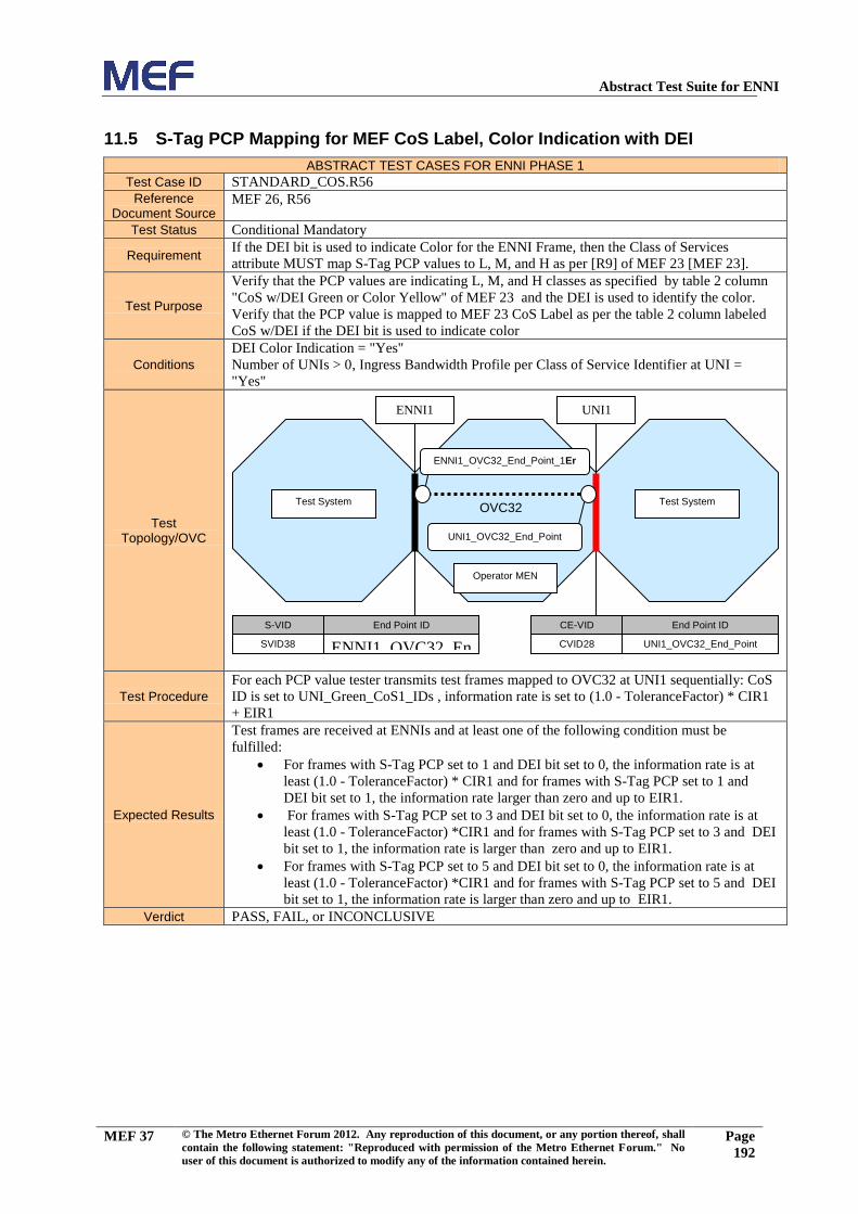
Abstract Test Suite for ENNI
MEF 37 © The Metro Ethernet Forum 2012. Any reproduction of this document, or any portion thereof, shall
contain the following statement: "Reproduced with permission of the Metro Ethernet Forum." No
user of this document is authorized to modify any of the information contained herein.
Page
192
11.5 S-Tag PCP Mapping for MEF CoS Label, Color Indication with DEI
ABSTRACT TEST CASES FOR ENNI PHASE 1
Test Case ID STANDARD_COS.R56
Reference Document Source
MEF 26, R56
Test Status Conditional Mandatory
Requirement If the DEI bit is used to indicate Color for the ENNI Frame, then the Class of Services
attribute MUST map S-Tag PCP values to L, M, and H as per [R9] of MEF 23 [MEF 23].
Test Purpose
Verify that the PCP values are indicating L, M, and H classes as specified by table 2 column
"CoS w/DEI Green or Color Yellow" of MEF 23 and the DEI is used to identify the color.
Verify that the PCP value is mapped to MEF 23 CoS Label as per the table 2 column labeled
CoS w/DEI if the DEI bit is used to indicate color
Conditions
DEI Color Indication = "Yes"
Number of UNIs > 0, Ingress Bandwidth Profile per Class of Service Identifier at UNI =
"Yes"
Test Topology/OVC
Test Procedure
For each PCP value tester transmits test frames mapped to OVC32 at UNI1 sequentially: CoS
ID is set to UNI_Green_CoS1_IDs , information rate is set to (1.0 - ToleranceFactor) * CIR1
+ EIR1
Expected Results
Test frames are received at ENNIs and at least one of the following condition must be
fulfilled:
For frames with S-Tag PCP set to 1 and DEI bit set to 0, the information rate is at
least (1.0 - ToleranceFactor) * CIR1 and for frames with S-Tag PCP set to 1 and
DEI bit set to 1, the information rate larger than zero and up to EIR1.
For frames with S-Tag PCP set to 3 and DEI bit set to 0, the information rate is at
least (1.0 - ToleranceFactor) *CIR1 and for frames with S-Tag PCP set to 3 and DEI
bit set to 1, the information rate is larger than zero and up to EIR1.
For frames with S-Tag PCP set to 5 and DEI bit set to 0, the information rate is at
least (1.0 - ToleranceFactor) *CIR1 and for frames with S-Tag PCP set to 5 and DEI
bit set to 1, the information rate is larger than zero and up to EIR1.
Verdict PASS, FAIL, or INCONCLUSIVE
Test System
Operator MEN
S-VID End Point ID
SVID38 ENNI1_OVC32_En
d_Point_1Error!
Reference source not found.
CE-VID End Point ID
CVID28 UNI1_OVC32_End_Point
UNI1
Test System
ENNI1
ENNI1_OVC32_End_Point_1Error! Reference source not
found.
UNI1_OVC32_End_Point
OVC32

Abstract Test Suite for ENNI
MEF 37 © The Metro Ethernet Forum 2012. Any reproduction of this document, or any portion thereof, shall
contain the following statement: "Reproduced with permission of the Metro Ethernet Forum." No
user of this document is authorized to modify any of the information contained herein.
Page
193
12 Test Group: ENNI Ingress Bandwidth Profile per CoS
Please note that the tests of Excess Information Rate (EIR) and of Egress bandwidth profile
implementations requires a controlled environment for the Operator MEN. Since there are no
performance guarantees on EIR/EBS, the system under test might drop frames below
EIR/EBS – which would be compliant with MEF26 but not helpful for the test purpose.
Similarly, if traffic moving through the network would exhibit noticeable frame delay
variation before hitting the Egress bandwidth profile, the test could not be carried out.
In the sections 12-15, the ATS assumes that the entity conducting the test is able to control
congestion in the Operator MEN during the test, ensuring that the tests can be carried out
according to their purposes.

Abstract Test Suite for ENNI
MEF 37 © The Metro Ethernet Forum 2012. Any reproduction of this document, or any portion thereof, shall
contain the following statement: "Reproduced with permission of the Metro Ethernet Forum." No
user of this document is authorized to modify any of the information contained herein.
Page
194
12.1 ENNI Ingress BWP per CoS with CIR>0, EIR=0, CF=0, EBS=0, CM=1
ABSTRACT TEST CASES FOR ENNI PHASE 1
Test Case ID ENNI_INGRESS_BWP_COS.R61.1
Reference Document Source
MEF 26, R61, R62, R82, R84, R86, R88
Test Status Mandatory
Requirement
[R61] When the Ingress Bandwidth Profile per Class of Service Identifier is in force for a
given ENNI Class of Service Identifier, suitable parameters <CIR, CBS, EIR, EBS, CF, CM>
as defined in Section 7.6.1 of [MEF 26] MUST be specified and the algorithm of Section
7.6.1 of [MEF 26] MUST be applied to all ingress ENNI Frames mapped to the OVC End
Point that have the given ENNI Class of Service Identifier.
[R62] The Bandwidth Profile Algorithm MUST be color-aware.
[R82] CIR MUST be 0
[R84] EIR MUST be 0
[R86] For a sequence of ENNI Frames, ,1,0,, jjjj ttjlt with arrival times at the
reference point jt and lengths jl , the level of compliance color assigned to each ENNI
Frame MUST be defined according to the algorithm in Figure 10 of [MEF 26].
[R88] The disposition of each ENNI Frame for delivery to each egress External Interface
MUST be as described in Table 11 of [MEF 26].
Test Purpose Verify that the ENNI ingress bandwidth profile per CoS with CIR>0 and EIR=0 and CF=0
will limit the information rate of the incoming Green traffic to CIR and drop all other frames.
Conditions
Color Aware for ENNI Ingress Bandwidth Profile per CoS = “Yes”
S-Tag PCP Color Indication = "Yes",
Ingress Bandwidth Profile per Class of Service Identifier at ENNI = "Yes"
Test Topology/OVC
Test Procedure
1. Tester transmits test frames mapped to OVC14 at ENNI1: CoS ID is set to
ENNI_Green_CoS1_IDs, information rate is 0.5*CIR1
2. Tester transmits test frames mapped to OVC14 at ENNI1: CoS ID is set to
ENNI_Green_CoS1_IDs, information rate is (1.0-ToleranceFactor)* CIR1
3. Tester transmits test frames mapped to OVC14 at ENNI1: CoS ID is set to
ENNI_Green_CoS1_IDs, information rate is 1.5*CIR1
4. Tester transmits test frames A mapped to OVC14 at ENNI1: CoS ID is set to
ENNI_Green_CoS1_IDs, information rate is 0.5*CIR1. Tester transmits test frames
B mapped to OVC14 at ENNI1: CoS ID is set to ENNI_Yellow_CoS1_IDs,
information rate is 0.1*CIR1
5. Tester transmits test frames mapped to OVC14 at ENNI1: CoS ID is set to
ENNI_Yellow_CoS1_IDs, information rate is 0.1*CIR1.
Expected Results
1. All test frames are received at UNI1.
2. All test frames are received at UNI1.
3. A number of frames representing traffic of at least “Flow Transmission Duration” *
(1 - ToleranceFactor) * CIR1 + (CBS1 * 8) and at most “Flow Transmission
Test System
Operator MEN
S-VID End Point ID
SVID18 ENNI1_OVC14_End_Point_1
CE-VID End Point ID
CVID11 UNI1_OVC14_End_Point
UNI1
Test System
ENNI1
ENNI1_OVC14_End_Point_1
UNI1_OVC14_End_Point
OVC14

Abstract Test Suite for ENNI
MEF 37 © The Metro Ethernet Forum 2012. Any reproduction of this document, or any portion thereof, shall
contain the following statement: "Reproduced with permission of the Metro Ethernet Forum." No
user of this document is authorized to modify any of the information contained herein.
Page
195
Duration” * (1 + ToleranceFactor) * CIR1 + (CBS1 * 8) are received at UNI1.
4. All test frames A are received at UNI1. Test frames B are not received at any
External Interface used in this test case.
5. Test frames are not received at any External Interface used in this test case.
Verdict PASS, FAIL, or INCONCLUSIVE

Abstract Test Suite for ENNI
MEF 37 © The Metro Ethernet Forum 2012. Any reproduction of this document, or any portion thereof, shall
contain the following statement: "Reproduced with permission of the Metro Ethernet Forum." No
user of this document is authorized to modify any of the information contained herein.
Page
196
12.2 ENNI Ingress BWP per CoS with CIR=0, CBS=0, EIR>0, CF=0, EBS>0,
CM=1
ABSTRACT TEST CASES FOR ENNI PHASE 1
Test Case ID ENNI_INGRESS_BWP_COS.R61.4
Reference Document Source
MEF 26, R61, R62, R82, R84, R86, R88
Test Status Mandatory
Requirement
[R61] When the Ingress Bandwidth Profile per Class of Service Identifier is in force for a
given ENNI Class of Service Identifier, suitable parameters <CIR, CBS, EIR, EBS, CF, CM>
as defined in Section 7.6.1 of [MEF 26] MUST be specified and the algorithm of Section
7.6.1 of [MEF 26] MUST be applied to all ingress ENNI Frames mapped to the OVC End
Point that have the given ENNI Class of Service Identifier.
[R62] The Bandwidth Profile Algorithm MUST be color-aware.
[R82] CIR MUST be 0
[R84] EIR MUST be 0
[R86] For a sequence of ENNI Frames, ,1,0,, jjjj ttjlt with arrival times at the
reference point jt and lengths jl , the level of compliance color assigned to each ENNI
Frame MUST be defined according to the algorithm in Figure 10 of [MEF 26].
[R88] The disposition of each ENNI Frame for delivery to each egress External Interface
MUST be as described in Table 11 of [MEF 26].
Test Purpose
Verify that the ENNI ingress bandwidth profile per CoS with CIR=0 and EIR>0, will limit the
total information rate of the incoming traffic to EIR and drop any excess traffic. All green
traffic must be discarded.
Conditions
Color Aware for ENNI Ingress Bandwidth Profile per CoS = “Yes”
S-Tag PCP Color Indication = "Yes",
Ingress Bandwidth Profile per Class of Service Identifier at ENNI = "Yes"
Test Topology/OVC
Test Procedure
1. Tester transmits test frames mapped to OVC17 at ENNI1: CoS ID is set to
ENNI_Green_CoS1_IDs, information rate is 0.5*EIR1
2. Tester transmits test frames mapped to OVC17 at ENNI1: CoS ID is set to
ENNI_Green_CoS1_IDs, information rate is (1.0 - ToleranceFactor) *EIR1
3. Tester transmits test frames mapped to OVC17 at ENNI1: CoS ID is set to
ENNI_Green_CoS1_IDs, information rate is 1.5*EIR1
4. Tester transmits test frames mapped to OVC17 at ENNI1: CoS ID is set to
ENNI_Yellow_CoS1_IDs, information rate is 0.5*EIR1
5. Tester transmits test frames mapped to OVC17 at ENNI1: CoS ID is set to
ENNI_Yellow_CoS1_IDs, information rate is (1.0 - ToleranceFactor) *EIR1
6. Tester transmits test frames mapped to OVC17 at ENNI1: CoS ID is set to
ENNI_Yellow_CoS1_IDs, information rate is 1.5*EIR1
7. Tester transmits test frames A mapped to OVC17 at ENNI1: CoS ID is set to
Test System
Operator MEN
S-VID End Point ID
SVID21 ENNI1_OVC17_End_Point_1
CE-VID End Point ID
CVID14 UNI1_OVC17_End_Point
UNI1
Test System
ENNI1
ENNI1_OVC17_End_Point_1
UNI1_OVC17_End_Point
OVC17

Abstract Test Suite for ENNI
MEF 37 © The Metro Ethernet Forum 2012. Any reproduction of this document, or any portion thereof, shall
contain the following statement: "Reproduced with permission of the Metro Ethernet Forum." No
user of this document is authorized to modify any of the information contained herein.
Page
197
ENNI_Green_CoS1_IDs, information rate is 0.4*EIR1. Tester transmits test frames
B mapped to OVC17 at ENNI1: CoS ID is set to ENNI_Yellow_CoS1_IDs,
information rate is 0.4*EIR1
8. Tester transmits test frames A mapped to OVC17 at ENNI1: CoS ID is set to
ENNI_Green_CoS1_IDs, information rate is 0.5*EIR1. Tester transmits test frames
B mapped to OVC17 at ENNI1: CoS ID is set to ENNI_Yellow_CoS1_IDs,
information rate is 0.5*EIR1
9. Tester transmits test frames A mapped to OVC17 at ENNI1: CoS ID is set to
ENNI_Green_CoS1_IDs, information rate is 0.6*EIR1. Tester transmits test frames
B mapped to OVC17 at ENNI1: CoS ID is set to ENNI_Yellow_CoS1_IDs,
information rate is 0.6*EIR1
Expected Results
1. No test frames are received at UNI1.
2. No test frames are received at UNI1.
3. No test frames are received at UNI1.
4. More than zero test frames are received at UNI1.
5. More than zero test frames are received at UNI1.
6. More than zero test frames are received at UNI1.
7. No test frames A are received at UNI1. More than zero test frames B are received at
UNI1.
8. No test frames A are received at UNI1. More than zero test frames B are received at
UNI1.
9. No test frames A are received at UNI1 More than zero test frames B are received at
UNI1.
Verdict PASS, FAIL, or INCONCLUSIVE

Abstract Test Suite for ENNI
MEF 37 © The Metro Ethernet Forum 2012. Any reproduction of this document, or any portion thereof, shall
contain the following statement: "Reproduced with permission of the Metro Ethernet Forum." No
user of this document is authorized to modify any of the information contained herein.
Page
198
12.3 ENNI Ingress BWP per CoS with CIR>0, CBS>0, EIR>0, CF=0, EBS>0,
CM=1
ABSTRACT TEST CASES FOR ENNI PHASE 1
Test Case ID ENNI_INGRESS_BWP_COS.R61.6
Reference Document Source
MEF 26, R61, R62, R82, R84, R86, R88
Test Status Mandatory
Requirement
[R61] When the Ingress Bandwidth Profile per Class of Service Identifier is in force for a
given ENNI Class of Service Identifier, suitable parameters <CIR, CBS, EIR, EBS, CF, CM>
as defined in Section 7.6.1 of [MEF 26] MUST be specified and the algorithm of Section
7.6.1 of [MEF 26] MUST be applied to all ingress ENNI Frames mapped to the OVC End
Point that have the given ENNI Class of Service Identifier.
[R62] The Bandwidth Profile Algorithm MUST be color-aware.
[R82] CIR MUST be 0
[R84] EIR MUST be 0
[R86] For a sequence of ENNI Frames, ,1,0,, jjjj ttjlt with arrival times at the
reference point jt and lengths jl , the level of compliance color assigned to each ENNI
Frame MUST be defined according to the algorithm in Figure 10 of [MEF 26].
[R88] The disposition of each ENNI Frame for delivery to each egress External Interface
MUST be as described in Table 11 of [MEF 26].
Test Purpose
Verify that the ENNI ingress bandwidth profile per CoS with CIR>0 and EIR>0, will limit the
information rate of the incoming Green traffic to CIR, limit the sum of the excess Green
traffic and the Yellow traffic to EIR and drop any excess traffic.
Conditions
S-Tag PCP Color Indication = "Yes",
Ingress Bandwidth Profile per Class of Service Identifier at ENNI = "Yes",
Color Aware for ENNI Ingress Bandwidth Profile per CoS = “Yes”
Test Topology/OVC
Test Procedure
1. Tester transmits test frames mapped to OVC19 at ENNI1: CoS ID is set to
ENNI_Green_CoS1_IDs, information rate is 0.5*CIR1
2. Tester transmits test frames mapped to OVC19 at ENNI1: CoS ID is set to
ENNI_Green_CoS1_IDs, information rate is (1.0 - ToleranceFactor) *CIR1
3. Tester transmits test frames mapped to OVC19 at ENNI1: CoS ID is set to
ENNI_Green_CoS1_IDs, information rate is (1.0 - ToleranceFactor)
*CIR1+0.5*EIR1
4. Tester transmits test frames mapped to OVC19 at ENNI1: CoS ID is set to
ENNI_Green_CoS1_IDs, information rate is (1.0 - ToleranceFactor)
*CIR1+1.0*EIR1
5. Tester transmits test frames mapped to OVC19 at ENNI1: CoS ID is set to
ENNI_Green_CoS1_IDs, information rate is (1.0 - ToleranceFactor)
*CIR1+1.5*EIR1
Test System
Operator MEN
S-VID End Point ID
SVID23 ENNI1_OVC19_End_Point_1
CE-VID End Point ID
CVID16 UNI1_OVC19_End_Point
UNI1
Test System
ENNI1
ENNI1_OVC19_End_Point_1
UNI1_OVC19_End_Point
OVC19

Abstract Test Suite for ENNI
MEF 37 © The Metro Ethernet Forum 2012. Any reproduction of this document, or any portion thereof, shall
contain the following statement: "Reproduced with permission of the Metro Ethernet Forum." No
user of this document is authorized to modify any of the information contained herein.
Page
199
6. Tester transmits test frames mapped to OVC19 at ENNI1: CoS ID is set to
ENNI_Yellow_CoS1_IDs, information rate is 0.5*EIR1
7. Tester transmits test frames mapped to OVC19 at ENNI1: CoS ID is set to
ENNI_Yellow_CoS1_IDs, information rate is (1.0 - ToleranceFactor) *EIR1
8. Tester transmits test frames mapped to OVC19 at ENNI1: CoS ID is set to
ENNI_Yellow_CoS1_IDs, information rate is 1.5*EIR1
9. Tester transmits test frames A mapped to OVC19 at ENNI1: CoS ID is set to
ENNI_Green_CoS1_IDs, information rate is 0.5*CIR1. Tester transmits test frames
mapped to OVC19 B at ENNI1: CoS ID is set to ENNI_Yellow_CoS1_IDs,
information rate is 0.5*EIR1.
10. Tester transmits test frames A mapped to OVC19 A at ENNI1: CoS ID is set to
ENNI_Green_CoS1_IDs, information rate is (1.0 - ToleranceFactor) *CIR1. Tester
transmits test frames B mapped to OVC19 at ENNI1: CoS ID is set to
ENNI_Yellow_CoS1_IDs, information rate is (1.0 - ToleranceFactor) *EIR1.
11. Tester transmits test frames A mapped to OVC19 at ENNI1: CoS ID is set to
ENNI_Green_CoS1_IDs, information rate is (1.0 - ToleranceFactor)
*CIR1+0.5*EIR1. Tester transmits test frames B mapped to OVC19 at ENNI1: CoS
ID is set to ENNI_Yellow_CoS1_IDs, information rate is 0.1*EIR1.
12. Tester transmits test frames A mapped to OVC19 at ENNI1: CoS ID is set to
ENNI_Green_CoS1_IDs, information rate is (1.0 - ToleranceFactor)
*CIR1+0.5*EIR1. Tester transmits test frames B mapped to OVC19 at ENNI1: CoS
ID is set to ENNI_Yellow_CoS1_IDs, information rate is 0.5*EIR1.
13. Tester transmits test frames A mapped to OVC19 at ENNI1: CoS ID is set to
ENNI_Green_CoS1_IDs, information rate is (1.0 - ToleranceFactor)
*CIR1+0.6*EIR1. Tester transmits test frames B mapped to OVC19 at ENNI1: CoS
ID is set to ENNI_Yellow_CoS1_IDs, information rate is 0.6*EIR1.
14. Tester transmits test frames A mapped to OVC19 at ENNI1: CoS ID is set to
ENNI_Green_CoS1_IDs, information rate is (1.0 - ToleranceFactor)
*CIR1+1.0*EIR1. Tester transmits test frames B mapped to OVC19 at ENNI1: CoS
ID is set to ENNI_Yellow_CoS1_IDs, information rate is 0.5*EIR1.
15. Tester transmits test frames A mapped to OVC19 at ENNI1: CoS ID is set to
ENNI_Green_CoS1_IDs, information rate is (1.0 - ToleranceFactor)
*CIR1+1.5*EIR1. Tester transmits test frames B mapped to OVC19 at ENNI1: CoS
ID is set to ENNI_Yellow_CoS1_IDs, information rate is 0.5*EIR1.
Expected Results
1. All test frames are received at UNI1.
2. All test frames are received at UNI1.
3. All test frames are received at UNI1.
4. All test frames are received at UNI1.
5. Test frames are partially received at UNI1: the information rate of the received test
frames is at least (1.0 - ToleranceFactor) * CIR1 .
6. More than zero test frames are received at UNI1.
7. More than zero test frames are received at UNI1.
8. More than zero test frames are received at UNI1.
9. All test frames A are received at UNI1. More than zero test frames B are received at
UNI1.
10. All test frames A are received at UNI1. More than zero test frames B are received at
UNI1.
11. A number of test frames A representing traffic of at least “Flow Transmission
Duration” * (1 - ToleranceFactor) * CIR1 + (CBS1 * 8) and at most “Flow
Transmission Duration” * (1 + ToleranceFactor) * CIR1 + (CBS1 * 8) are received at
UNI1. More than zero test frames B are received at UNI1.
12. A number of test frames A representing traffic of at least “Flow Transmission
Duration” * (1 - ToleranceFactor) * CIR1 + (CBS1 * 8) and at most “Flow
Transmission Duration” * (1 + ToleranceFactor) * CIR1 + (CBS1 * 8) are received at
UNI1. More than zero test frames B are received at UNI1.
13. A number of test frames A representing traffic of least “Flow Transmission
Duration” * (1 - ToleranceFactor) * CIR1 + (CBS1 * 8) A are received at UNI1.
More than zero test frames B are received at UNI1.
14. A number of test frames A representing traffic of least “Flow Transmission
Duration” * (1 - ToleranceFactor) * CIR1 + (CBS1 * 8)are received at UNI1. More
than zero test frames B are received at UNI1.

Abstract Test Suite for ENNI
MEF 37 © The Metro Ethernet Forum 2012. Any reproduction of this document, or any portion thereof, shall
contain the following statement: "Reproduced with permission of the Metro Ethernet Forum." No
user of this document is authorized to modify any of the information contained herein.
Page
200
15. A number of test frames A representing traffic of least “Flow Transmission
Duration” * (1 - ToleranceFactor) * CIR1 + (CBS1 * 8) are received at UNI1. More
than zero test frames B are received at UNI1.
Verdict PASS, FAIL, or INCONCLUSIVE

Abstract Test Suite for ENNI
MEF 37 © The Metro Ethernet Forum 2012. Any reproduction of this document, or any portion thereof, shall
contain the following statement: "Reproduced with permission of the Metro Ethernet Forum." No
user of this document is authorized to modify any of the information contained herein.
Page
201
12.4 ENNI Ingress BWP per CoS: Commited Burst Size, EBS = 0
ABSTRACT TEST CASES FOR ENNI PHASE 1
Test Case ID ENNI_INGRESS_BWP_COS. R61.8
Reference Document Source
MEF 26, R61, R83
Test Status Mandatory
Requirement
[R61] When the Ingress Bandwidth Profile per Class of Service Identifier is in force for a
given ENNI Class of Service Identifier, suitable parameters <CIR, CBS, EIR, EBS, CF, CM>
as defined in Section 7.6.1 of [MEF 26] MUST be specified and the algorithm of Section
7.6.1 of [MEF 26] MUST be applied to all ingress ENNI Frames mapped to the OVC End
Point that have the given ENNI Class of Service Identifier.
[R83] When CIR > 0, CBS MUST be greater than or equal to the largest Maximum
Transmission Unit size allowed for the ENNI Frames that the Bandwidth Profile applies to.
Test Purpose Verify that ENNI ingress bandwidth profile per CoS with CIR>0 will forward bursts of Green
traffic of at least MTU size and at most CBS size.
Conditions
Color Aware for ENNI Ingress Bandwidth Profile per CoS = “Yes”
S-Tag PCP Color Indication = "Yes",
Ingress Bandwidth Profile per Class of Service Identifier at ENNI = "Yes"
Test Topology/OVC
Test Procedure
1. Tester transmits bursts of test frames mapped to OVC14 at ENNI1: CoS ID is set to
ENNI_Green_CoS1_IDs, total burst size is 0.5*CBS1 octets, at a rate of 1 burst
every 1 second
2. Tester transmits bursts of test frames mapped to OVC14 at ENNI1: CoS ID is set to
ENNI_Green_CoS1_IDs, total burst size is 1.0*CBS1 octets rounded down to the
next whole frame, at a rate of 1 burst every 1 second
3. Tester transmits bursts of test frames mapped to OVC14 at ENNI1: CoS ID is set to
ENNI_Green_CoS1_IDs, total burst size rounded up to the nearest whole frame is
1.25 * CBS1 * BIR /(BIR-CIR1), at a rate of 1 burst every 1 second
4. Tester transmits bursts of test frames mapped to OVC14 at ENNI1: CoS ID is set to
ENNI_Green_CoS1_IDs. Perform the burst procedure described in section 17.3 in
this document.
Expected Results
1. All test frames are received at UNI1.
2. All test frames are received at UNI1.
3. The amount of traffic received at UNI1 is lower bound by NG and upper bound by NG
plus half of the transmitted traffic in excess of NG.
4. All expected test frames are received at UNI1.
Verdict PASS, FAIL, or INCONCLUSIVE
Test System
Operator MEN
S-VID End Point ID
SVID18 ENNI1_OVC14_End_Point_1
CE-VID End Point ID
CVID11 UNI1_OVC14_End_Point
UNI1
Test System
ENNI1
ENNI1_OVC14_End_Point_1
UNI1_OVC14_End_Point
OVC14

Abstract Test Suite for ENNI
MEF 37 © The Metro Ethernet Forum 2012. Any reproduction of this document, or any portion thereof, shall
contain the following statement: "Reproduced with permission of the Metro Ethernet Forum." No
user of this document is authorized to modify any of the information contained herein.
Page
202
12.5 ENNI Ingress BWP per CoS: Excess Burst Size.
ABSTRACT TEST CASES FOR ENNI PHASE 1
Test Case ID ENNI_INGRESS_BWP_COS. R61.9
Reference Document Source
MEF 26, R61, R85
Test Status Mandatory
Requirement
[R61] When the Ingress Bandwidth Profile per Class of Service Identifier is in force for a
given ENNI Class of Service Identifier, suitable parameters <CIR, CBS, EIR, EBS, CF, CM>
as defined in Section 7.6.1 of [MEF 26] MUST be specified and the algorithm of Section
7.6.1 of [MEF 26] MUST be applied to all ingress ENNI Frames mapped to the OVC End
Point that have the given ENNI Class of Service Identifier.
[R85] When EIR > 0, EBS MUST be greater than or equal to the largest Maximum
Transmission Unit size allowed for the ENNI Frames that the Bandwidth Profile applies to.
Test Purpose Verify that ENNI ingress bandwidth profile per CoS with CIR>0 will forward bursts of
Yellow traffic of at least MTU size and at most EBS size.
Conditions
Color Aware for ENNI Ingress Bandwidth Profile per CoS = “Yes”
S-Tag PCP Color Indication = "Yes",
Ingress Bandwidth Profile per Class of Service Identifier at ENNI = "Yes"
Test Topology/OVC
Test Procedure
1. Tester transmits bursts of test frames mapped to OVC17 at ENNI1: CoS ID is set to
ENNI_Yellow_CoS1_IDs, total burst size is 0.5*EBS1 octets, at a rate of 1 burst
every 1 second
2. Tester transmits bursts of test frames mapped to OVC17 at ENNI1: CoS ID is set to
ENNI_Yellow_CoS1_IDs, total burst size is 1.0*EBS1 octets rounded down to the
next whole frame, at a rate of 1 burst every 1 second
3. Tester transmits bursts of test frames mapped to OVC17 at ENNI1: CoS ID is set to
ENNI_Yellow_CoS1_IDs, total burst size is (1.25* EBS1 rounded up to the nearest
whole frame) * BIR /(BIR-EIR1), at a rate of 1 burst every 1 second
4. Tester transmits bursts of test frames mapped to OVC17 at ENNI1: CoS ID is set to
ENNI_Yellow_CoS1_IDs. Perform the burst test procedure described in section 17.3
in this document).
Expected Results
1. More than zero test frames are received at UNI1.
2. More than zero test frames are received at UNI1.
3. The amount of traffic received at UNI1 is larger than zero frames and upper bound by
NY plus half of the transmitted traffic in excess of NY.
4. All green test frames are received at UNI1, and more than zero yellow frames are
received.
Verdict PASS, FAIL, or INCONCLUSIVE
Test System
Operator MEN
S-VID End Point ID
SVID21 ENNI1_OVC17_End_Point_1
CE-VID End Point ID
CVID14 UNI1_OVC17_End_Point
UNI1
Test System
ENNI1
ENNI1_OVC17_End_Point_1
UNI1_OVC17_End_Point
OVC17

Abstract Test Suite for ENNI
MEF 37 © The Metro Ethernet Forum 2012. Any reproduction of this document, or any portion thereof, shall
contain the following statement: "Reproduced with permission of the Metro Ethernet Forum." No
user of this document is authorized to modify any of the information contained herein.
Page
203
13 Test Group: ENNI Egress Bandwidth Profile per CoS

Abstract Test Suite for ENNI
MEF 37 © The Metro Ethernet Forum 2012. Any reproduction of this document, or any portion thereof, shall
contain the following statement: "Reproduced with permission of the Metro Ethernet Forum." No
user of this document is authorized to modify any of the information contained herein.
Page
204
13.1 ENNI Egress BWP per CoS with CIR>0, EIR=0, CF=0, EBS=0, CM=1
ABSTRACT TEST CASES FOR ENNI PHASE 1
Test Case ID ENNI_EGRESS_BWP_COS.R63.1
Reference Document Source
MEF 26, R63, R64, R82, R84, R89
Test Status Conditional Mandatory
Requirement
[R63] When the Egress Bandwidth Profile per Class of Service Identifier is in force for a
given ENNI Class of Service Identifier, suitable parameters <CIR, CBS, EIR, EBS, CF, CM>
as defined in Section 7.6.1 of [MEF 26] MUST be specified and all egress ENNI Frames
mapped to the OVC End Point with the given Class of Service Identifier MUST have the
property defined in Section 7.6.3 of [MEF 26].
[R64] The Color Mode for the Bandwidth Profile Algorithm MUST be color-aware.
[R82] CIR MUST be 0
[R84] EIR MUST be 0
[R89] When a sequence of egress ENNI Frames with arrival times and lengths at the ENNI,
0,, jlt jj are subjected to an Egress Bandwidth Profile with parameters <CIR, CBS,
EIR, EBS, CF, CM>, the result of applying the algorithm of Section 7.6.1 of [MEF 26] to
these frames MUST be to declare each ENNI Frame either Green or Yellow.
Test Purpose Verify that the ENNI egress bandwidth profile per CoS with CIR>0 and EIR=0 and CF=0 will
limit the information rate of the incoming Green traffic to CIR and drop all other frames.
Conditions
Color Aware for ENNI Egress Bandwidth Profile per CoS = “Yes”
S-Tag PCP Color Indication = "Yes",
Egress Bandwidth Profile per Class of Service Identifier at ENNI = "Yes"
Test Topology/OVC
Test Procedure
1. Tester transmits test frames mapped to OVC14 at UNI1: CoS ID is set to
EI_Green_CoS1_IDs, information rate is 0.5*CIR1
2. Tester transmits test frames mapped to OVC14 at UNI1: CoS ID is set to
EI_Green_CoS1_IDs, information rate is (1.0 - ToleranceFactor) *CIR1
3. Tester transmits test frames mapped to OVC14 at UNI1: CoS ID is set to
EI_Green_CoS1_IDs, information rate is 1.5*CIR1
4. Tester transmits test frames A mapped to OVC14 at UNI1: CoS ID is set to
EI_Green_CoS1_IDs, information rate is 0.5*CIR1. Tester transmits test frames B
mapped to OVC14 at UNI1: CoS ID is set to EI_Yellow_CoS1_IDs, information rate
is 0.1*CIR1
5. Tester transmits test frames mapped to OVC14 at UNI1: CoS ID is set to
EI_Yellow_CoS1_IDs, information rate is 0.1*CIR1.
Expected Results
1. All test frames are received at ENNI1.
2. All test frames are received at ENNI1.
3. Test frames are partially received at ENNI1: in total a number of frames representing
traffic of at least “Flow Transmission Duration” * (1 - ToleranceFactor) * CIR1 +
(CBS1 * 8) and at most “Flow Transmission Duration” * (1 + ToleranceFactor) *
CIR1 + (CBS1 * 8):
Test System
Operator MEN
S-VID End Point ID
SVID18 ENNI1_OVC14_End_Point_1
CE-VID End Point ID
CVID11 UNI1_OVC14_End_Point
UNI1
Test System
ENNI1
ENNI1_OVC14_End_Point_1
Error! Reference source not found.
OVC14

Abstract Test Suite for ENNI
MEF 37 © The Metro Ethernet Forum 2012. Any reproduction of this document, or any portion thereof, shall
contain the following statement: "Reproduced with permission of the Metro Ethernet Forum." No
user of this document is authorized to modify any of the information contained herein.
Page
205
4. All test frames A are received at ENNI1. Test frames B are not received at any
External Interface used in this test.
5. Test frames are not received at any External Interface used in this test.
Verdict PASS, FAIL, or INCONCLUSIVE

Abstract Test Suite for ENNI
MEF 37 © The Metro Ethernet Forum 2012. Any reproduction of this document, or any portion thereof, shall
contain the following statement: "Reproduced with permission of the Metro Ethernet Forum." No
user of this document is authorized to modify any of the information contained herein.
Page
206
13.2 ENNI Egress BWP per CoS with CIR=0, EIR>0, CF=0, EBS>0, CM=1
ABSTRACT TEST CASES FOR ENNI PHASE 1
Test Case ID ENNI_EGRESS_BWP_COS.R63.4
Reference Document Source
MEF 26, R63, R64, R82, R84, R89
Test Status Conditional Mandatory
Requirement
[R63] When the Egress Bandwidth Profile per Class of Service Identifier is in force for a
given ENNI Class of Service Identifier, suitable parameters <CIR, CBS, EIR, EBS, CF, CM>
as defined in Section 7.6.1 of [MEF 26] MUST be specified and all egress ENNI Frames
mapped to the OVC End Point with the given Class of Service Identifier MUST have the
property defined in Section 7.6.3 of [MEF 26].
[R64] The Color Mode for the Bandwidth Profile Algorithm MUST be color-aware.
[R82] CIR MUST be 0
[R84] EIR MUST be 0
[R89] When a sequence of egress ENNI Frames with arrival times and lengths at the ENNI,
0,, jlt jj are subjected to an Egress Bandwidth Profile with parameters <CIR, CBS,
EIR, EBS, CF, CM>, the result of applying the algorithm of Section 7.6.1 of [MEF 26] to
these frames MUST be to declare each ENNI Frame either Green or Yellow.
Test Purpose
Verify that the ENNI egress bandwidth profile per CoS with CIR=0 and EIR>0, will limit the
total information rate of the incoming traffic to EIR and drop any excess traffic. All green
traffic must be discarded.
Conditions
Color Aware for ENNI Egress Bandwidth Profile per CoS = “Yes”
S-Tag PCP Color Indication = "Yes",
Egress Bandwidth Profile per Class of Service Identifier at ENNI = "Yes"
Test Topology/OVC
Test Procedure
1. Tester transmits test frames mapped to OVC17 at UNI1: CoS ID is set to
EI_Green_CoS1_IDs, information rate is 0.5*EIR1
2. Tester transmits test frames mapped to OVC17 at UNI1: CoS ID is set to
EI_Green_CoS1_IDs, information rate is (1.0 - ToleranceFactor) *EIR1
3. Tester transmits test frames mapped to OVC17 at UNI1: CoS ID is set to
EI_Green_CoS1_IDs, information rate is 1.5*EIR1
4. Tester transmits test frames mapped to OVC17 at UNI1: CoS ID is set to
EI_Yellow_CoS1_IDs, information rate is 0.5*EIR1
5. Tester transmits test frames mapped to OVC17 at UNI1: CoS ID is set to
EI_Yellow_CoS1_IDs, information rate is (1.0 - ToleranceFactor) *EIR1
6. Tester transmits test frames mapped to OVC17 at UNI1: CoS ID is set to
EI_Yellow_CoS1_IDs, information rate is 1.5*EIR1
7. Tester transmits test frames A mapped to OVC17 at UNI1: CoS ID is set to
EI_Green_CoS1_IDs, information rate is 0.4*EIR1. Tester transmits test frames B
mapped to OVC17 at UNI1: CoS ID is set to EI_Yellow_CoS1_IDs, information rate
is 0.4*EIR1
8. Tester transmits test frames A mapped to OVC17 at UNI1: CoS ID is set to
Test System
Operator MEN
S-VID End Point ID
SVID21 ENNI1_OVC17_End_Point_1
CE-VID End Point ID
CVID14 UNI1_OVC17_End_Point
UNI1
Test System
ENNI1
ENNI1_OVC17_End_Point_1
UNI1_OVC17_End_Point
OVC17

Abstract Test Suite for ENNI
MEF 37 © The Metro Ethernet Forum 2012. Any reproduction of this document, or any portion thereof, shall
contain the following statement: "Reproduced with permission of the Metro Ethernet Forum." No
user of this document is authorized to modify any of the information contained herein.
Page
207
EI_Green_CoS1_IDs, information rate is 0.5*EIR1. Tester transmits test frames B
mapped to OVC17 at UNI1: CoS ID is set to EI_Yellow_CoS1_IDs, information rate
is 0.5*EIR1
9. Tester transmits test frames A mapped to OVC17 at UNI1: CoS ID is set to
EI_Green_CoS1_IDs, information rate is 0.6*EIR1. Tester transmits test frames B
mapped to OVC17 at UNI1: CoS ID is set to EI_Yellow_CoS1_IDs, information rate
is 0.6*EIR1
Expected Results
1. No test frames are received at ENNI1.
2. No test frames are received at ENNI1.
3. No test frames are received at ENNI1.
4. More than zero test frames are received at ENNI1.
5. More than zero test frames are received at ENNI1.
6. More than zero test frames are received at ENNI1.
7. No test frames A are received at ENNI1. More than zero test frames B are received at
ENNI1.
8. No test frames A are received at ENNI1. More than zero test frames B are received at
ENNI1.
9. No test frames A are received at ENNI1. More than zero test frames B are received at
ENNI1.
Verdict PASS, FAIL, or INCONCLUSIVE
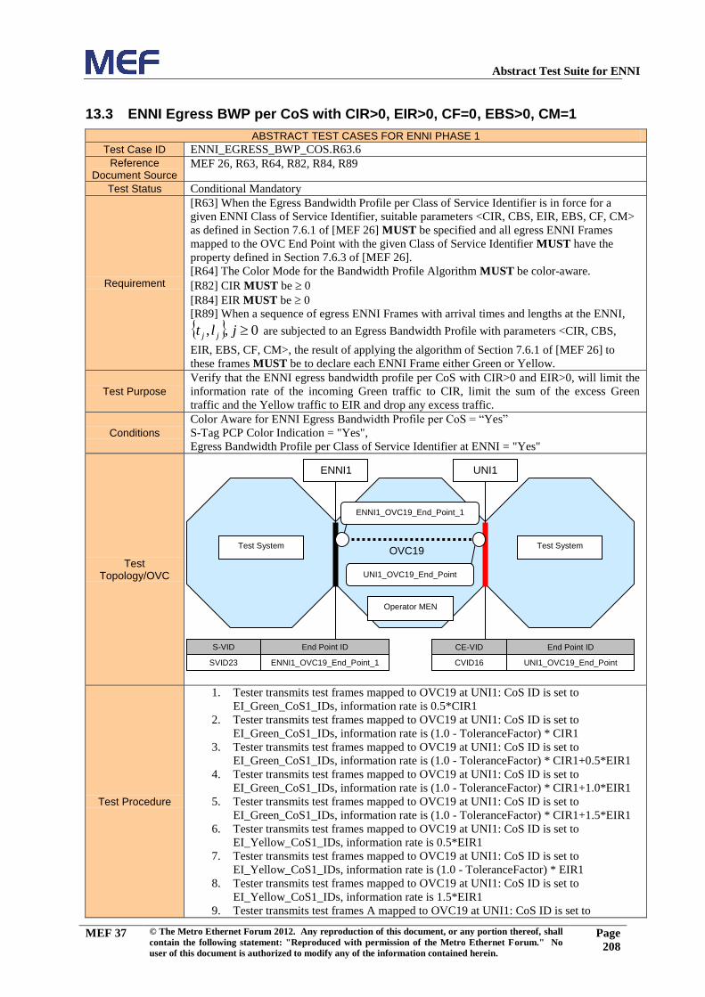
Abstract Test Suite for ENNI
MEF 37 © The Metro Ethernet Forum 2012. Any reproduction of this document, or any portion thereof, shall
contain the following statement: "Reproduced with permission of the Metro Ethernet Forum." No
user of this document is authorized to modify any of the information contained herein.
Page
208
13.3 ENNI Egress BWP per CoS with CIR>0, EIR>0, CF=0, EBS>0, CM=1
ABSTRACT TEST CASES FOR ENNI PHASE 1
Test Case ID ENNI_EGRESS_BWP_COS.R63.6
Reference Document Source
MEF 26, R63, R64, R82, R84, R89
Test Status Conditional Mandatory
Requirement
[R63] When the Egress Bandwidth Profile per Class of Service Identifier is in force for a
given ENNI Class of Service Identifier, suitable parameters <CIR, CBS, EIR, EBS, CF, CM>
as defined in Section 7.6.1 of [MEF 26] MUST be specified and all egress ENNI Frames
mapped to the OVC End Point with the given Class of Service Identifier MUST have the
property defined in Section 7.6.3 of [MEF 26].
[R64] The Color Mode for the Bandwidth Profile Algorithm MUST be color-aware.
[R82] CIR MUST be 0
[R84] EIR MUST be 0
[R89] When a sequence of egress ENNI Frames with arrival times and lengths at the ENNI,
0,, jlt jj are subjected to an Egress Bandwidth Profile with parameters <CIR, CBS,
EIR, EBS, CF, CM>, the result of applying the algorithm of Section 7.6.1 of [MEF 26] to
these frames MUST be to declare each ENNI Frame either Green or Yellow.
Test Purpose
Verify that the ENNI egress bandwidth profile per CoS with CIR>0 and EIR>0, will limit the
information rate of the incoming Green traffic to CIR, limit the sum of the excess Green
traffic and the Yellow traffic to EIR and drop any excess traffic.
Conditions
Color Aware for ENNI Egress Bandwidth Profile per CoS = “Yes”
S-Tag PCP Color Indication = "Yes",
Egress Bandwidth Profile per Class of Service Identifier at ENNI = "Yes"
Test Topology/OVC
Test Procedure
1. Tester transmits test frames mapped to OVC19 at UNI1: CoS ID is set to
EI_Green_CoS1_IDs, information rate is 0.5*CIR1
2. Tester transmits test frames mapped to OVC19 at UNI1: CoS ID is set to
EI_Green_CoS1_IDs, information rate is (1.0 - ToleranceFactor) * CIR1
3. Tester transmits test frames mapped to OVC19 at UNI1: CoS ID is set to
EI_Green_CoS1_IDs, information rate is (1.0 - ToleranceFactor) * CIR1+0.5*EIR1
4. Tester transmits test frames mapped to OVC19 at UNI1: CoS ID is set to
EI_Green_CoS1_IDs, information rate is (1.0 - ToleranceFactor) * CIR1+1.0*EIR1
5. Tester transmits test frames mapped to OVC19 at UNI1: CoS ID is set to
EI_Green_CoS1_IDs, information rate is (1.0 - ToleranceFactor) * CIR1+1.5*EIR1
6. Tester transmits test frames mapped to OVC19 at UNI1: CoS ID is set to
EI_Yellow_CoS1_IDs, information rate is 0.5*EIR1
7. Tester transmits test frames mapped to OVC19 at UNI1: CoS ID is set to
EI_Yellow_CoS1_IDs, information rate is (1.0 - ToleranceFactor) * EIR1
8. Tester transmits test frames mapped to OVC19 at UNI1: CoS ID is set to
EI_Yellow_CoS1_IDs, information rate is 1.5*EIR1
9. Tester transmits test frames A mapped to OVC19 at UNI1: CoS ID is set to
Test System
Operator MEN
S-VID End Point ID
SVID23 ENNI1_OVC19_End_Point_1
CE-VID End Point ID
CVID16 UNI1_OVC19_End_Point
UNI1
Test System
ENNI1
ENNI1_OVC19_End_Point_1
UNI1_OVC19_End_Point
OVC19

Abstract Test Suite for ENNI
MEF 37 © The Metro Ethernet Forum 2012. Any reproduction of this document, or any portion thereof, shall
contain the following statement: "Reproduced with permission of the Metro Ethernet Forum." No
user of this document is authorized to modify any of the information contained herein.
Page
209
EI_Green_CoS1_IDs, information rate is 0.5*CIR1. Tester transmits test frames B
mapped to OVC19 at External Interface not equal to ENNI1: CoS ID is set to
EI_Yellow_CoS1_IDs, information rate is 0.5*EIR1.
10. Tester transmits test frames A mapped to OVC19 at UNI1: CoS ID is set to
EI_Green_CoS1_IDs, information rate is (1.0 - ToleranceFactor) * CIR1. Tester
transmits test frames B mapped to OVC19 at UNI1: CoS ID is set to
EI_Yellow_CoS1_IDs, information rate is (1.0 - ToleranceFactor) EIR1.
11. Tester transmits test frames A mapped to OVC19 at UNI1: CoS ID is set to
EI_Green_CoS1_IDs, information rate is (1.0 - ToleranceFactor) CIR1+0.5*EIR1.
Tester transmits test frames B mapped to OVC19 at UNI1: CoS ID is set to
EI_Yellow_CoS1_IDs, information rate is 0.1*EIR1.
12. Tester transmits test frames A mapped to OVC19 at UNI1: CoS ID is set to
EI_Green_CoS1_IDs, information rate is (1.0 - ToleranceFactor) CIR1+0.5*EIR1.
Tester transmits test frames B mapped to OVC19 at UNI1: CoS ID is set to
EI_Yellow_CoS1_IDs, information rate is 0.5*EIR1.
13. Tester transmits test frames A mapped to OVC19 at UNI1: CoS ID is set to
EI_Green_CoS1_IDs, information rate is (1.0 - ToleranceFactor) CIR1+0.6*EIR1.
Tester transmits test frames B mapped to OVC19 at UNI1: CoS ID is set to
EI_Yellow_CoS1_IDs, information rate is 0.6*EIR1.
14. Tester transmits test frames A mapped to OVC19 at UNI1: CoS ID is set to
EI_Green_CoS1_IDs, information rate is (1.0 - ToleranceFactor) CIR1+1.0*EIR1.
Tester transmits test B frames mapped to OVC19 at UNI1: CoS ID is set to
EI_Yellow_CoS1_IDs, information rate is 0.5*EIR1.
15. Tester transmits test frames A mapped to OVC19 at UNI1: CoS ID is set to
EI_Green_CoS1_IDs, information rate is (1.0 - ToleranceFactor) CIR1+1.5*EIR1.
Tester transmits test frames B mapped to OVC19 at UNI1: CoS ID is set to
EI_Yellow_CoS1_IDs, information rate is 0.5*EIR1.
Expected Results
1. All test frames are received at ENNI1.
2. All test frames are received at ENNI1.
3. All test frames are received at ENNI1.
4. All test frames are received at ENNI1.
5. Test frames are partially received at ENNI1: the information rate of the received test
frames is at least (1.0 - ToleranceFactor) * CIR1.
6. More than zero test frames are received at ENNI1.
7. More than zero test frames are received at ENNI1.
8. More than zero test frames are partially received at ENNI1.
9. All test frames A are received at ENNI1. More than zero test frames B are received at
ENNI1.
10. All test frames A are received at ENNI1. More than zero test frames B are received at
ENNI1.
11. All test frames A are received at ENNI1. More than zero test frames B are received at
ENNI1.
12. All test frames A are received at ENNI1. More than zero test frames B are received at
ENNI1.
13. A number of test frames A representing traffic of least “Flow Transmission
Duration” * (1 - ToleranceFactor) * CIR1 + (CBS1 * 8) are received at ENNI1.
More than zero test frames B are received at ENNI1.
14. Test frames A are partially received at ENNI1: the information rate of the received
test frames is at least (1.0 - ToleranceFactor)*CIR1. More than zero test frames B are
received at ENNI1.
15. Test frames A are partially received at ENNI1: the information rate of the received
test frames is at least (1.0 - ToleranceFactor)*CIR1. More than zero test frames B are
received at ENNI1.
Verdict PASS, FAIL, or INCONCLUSIVE

Abstract Test Suite for ENNI
MEF 37 © The Metro Ethernet Forum 2012. Any reproduction of this document, or any portion thereof, shall
contain the following statement: "Reproduced with permission of the Metro Ethernet Forum." No
user of this document is authorized to modify any of the information contained herein.
Page
210
13.4 ENNI Egress BWP per CoS: Excess Burst Size.
ABSTRACT TEST CASES FOR ENNI PHASE 1
Test Case ID ENNI_EGRESS_BWP_COS.R63.9
Reference Document Source
MEF 26, R63, R85
Test Status Conditional Mandatory
Requirement
[R63] When the Egress Bandwidth Profile per Class of Service Identifier is in force for a
given ENNI Class of Service Identifier, suitable parameters <CIR, CBS, EIR, EBS, CF, CM>
as defined in Section 7.6.1 of [MEF 26] MUST be specified and all egress ENNI Frames
mapped to the OVC End Point with the given Class of Service Identifier MUST have the
property defined in Section 7.6.3 of [MEF 26].
[R85] When EIR > 0, EBS MUST be greater than or equal to the largest Maximum
Transmission Unit size allowed for the ENNI Frames that the Bandwidth Profile applies to.
Test Purpose Verify that ENNI egress bandwidth profile per CoS with CIR>0 will forward bursts of Yellow
traffic of at least MTU size and at most EBS size.
Conditions
Color Aware for ENNI Egress Bandwidth Profile per CoS = “Yes”
S-Tag PCP Color Indication = "Yes",
Egress Bandwidth Profile per Class of Service Identifier at ENNI = "Yes"
Test Topology/OVC
Test Procedure
1. Tester transmits bursts of test frames mapped to OVC17 at UNI1: CoS ID is set to
EI_Yellow_CoS1_IDs, total burst size is 0.5* EBS1 octets, at a rate of 1 burst every
1 second
2. Tester transmits bursts of test frames mapped to OVC17 at UNI1: CoS ID is set to
EI_Yellow_CoS1_IDs, total burst size is 1.0*EBS1 octets rounded down to the next
whole frame, at a rate of 1 burst every 1 second
3. Tester transmits bursts of test frames mapped to OVC17 at UNI1: CoS ID is set to
EI_Yellow_CoS1_IDs, total burst size is (1.25*EBS1 rounded up to the nearest
whole frame) * BIR /(BIR-CIR1), at a rate of 1 burst every 1 second
4. Tester transmits bursts of test frames mapped to OVC17 at UNI1: CoS ID is set to
EI_Yellow_CoS1_IDs. Perform the burst procedure described in section 17.3 in this
document.
Expected Results
1. More than zero test frames are received at ENNI1.
2. More than zero test frames are received at ENNI1.
3. The amount of traffic received at UNI1 is larger than zero frames and upper bound by
NY plus half of the transmitted traffic in excess of NY All green test frames are
received at ENNI1, and more than zero yellow frames are received.
Verdict PASS, FAIL, or INCONCLUSIVE
Test System
Operator MEN
S-VID End Point ID
SVID21 ENNI1_OVC17_End_Point_1
CE-VID End Point ID
CVID14 UNI1_OVC17_End_Point
UNI1
Test System
ENNI1
ENNI1_OVC17_End_Point_1
UNI1_OVC17_End_Point
OVC17

Abstract Test Suite for ENNI
MEF 37 © The Metro Ethernet Forum 2012. Any reproduction of this document, or any portion thereof, shall
contain the following statement: "Reproduced with permission of the Metro Ethernet Forum." No
user of this document is authorized to modify any of the information contained herein.
Page
211
13.5 ENNI Egress BWP per CoS: Commited Burst Size, EBS = 0
ABSTRACT TEST CASES FOR ENNI PHASE 1
Test Case ID ENNI_EGRESS_BWP_COS.R63.8
Reference Document Source
MEF 26, R63, R83
Test Status Conditional Mandatory
Requirement
[R63] When the Egress Bandwidth Profile per Class of Service Identifier is in force for a
given ENNI Class of Service Identifier, suitable parameters <CIR, CBS, EIR, EBS, CF, CM>
as defined in Section 7.6.1 of [MEF 26] MUST be specified and all egress ENNI Frames
mapped to the OVC End Point with the given Class of Service Identifier MUST have the
property defined in Section 7.6.3 of [MEF 26].
[R83] When CIR > 0, CBS MUST be greater than or equal to the largest Maximum
Transmission Unit size allowed for the ENNI Frames that the Bandwidth Profile applies to.
Test Purpose Verify that ENNI egress bandwidth profile per CoS with CIR>0 will forward bursts of Green
traffic of at least MTU size and at most CBS size.
Conditions
Color Aware for ENNI Egress Bandwidth Profile per CoS = “Yes”
S-Tag PCP Color Indication = "Yes",
Egress Bandwidth Profile per Class of Service Identifier at ENNI = "Yes"
Test Topology/OVC
Test Procedure
1. Tester transmits bursts of test frames mapped to OVC14 at UNI1: CoS ID is set to
EI_Green_CoS1_IDs, total burst size is 0.5*CBS1-octets, at a rate of 1 burst every 1
second
2. Tester transmits bursts of test frames mapped to OVC14 at UNI1: CoS ID is set to
EI_Green_CoS1_IDs, total burst size is 1.0*CBS1 octets rounded down to the next
whole frame, at a rate of 1 burst every 1 second
3. Tester transmits bursts of test frames mapped to OVC14 at UNI1: CoS ID is set to
EI_Green_CoS1_IDs, total burst size is (1.25*CBS1 rounded up to the nearest whole
frame) * BIR /(BIR-CIR1), at a rate of 1 burst every 1 second
4. Tester transmits bursts of test frames mapped to OVC14 at interface not equal to
ENNI1: CoS ID is set to EI_Green_CoS1_IDs. Perform the burst procedure
described in section 17.3 in this document.
Expected Results
1. All test frames are received at ENNI1.
2. All test frames are received at ENNI1.
3. The amount of traffic received at UNI1 is lower bound by NG and upper bound by
NG plus half of the transmitted traffic in excess of NG.All expected test frames are
received at ENNI1.
Verdict PASS, FAIL, or INCONCLUSIVE
14 Test Group: UNI Ingress Bandwidth Profile per CoS
Test System
Operator MEN
S-VID End Point ID
SVID18 ENNI1_OVC14_End_Point_1
CE-VID End Point ID
CVID11 UNI1_OVC14_End_Point
UNI1
Test System
ENNI1
ENNI1_OVC14_End_Point_1
Error! Reference source not found.
OVC14
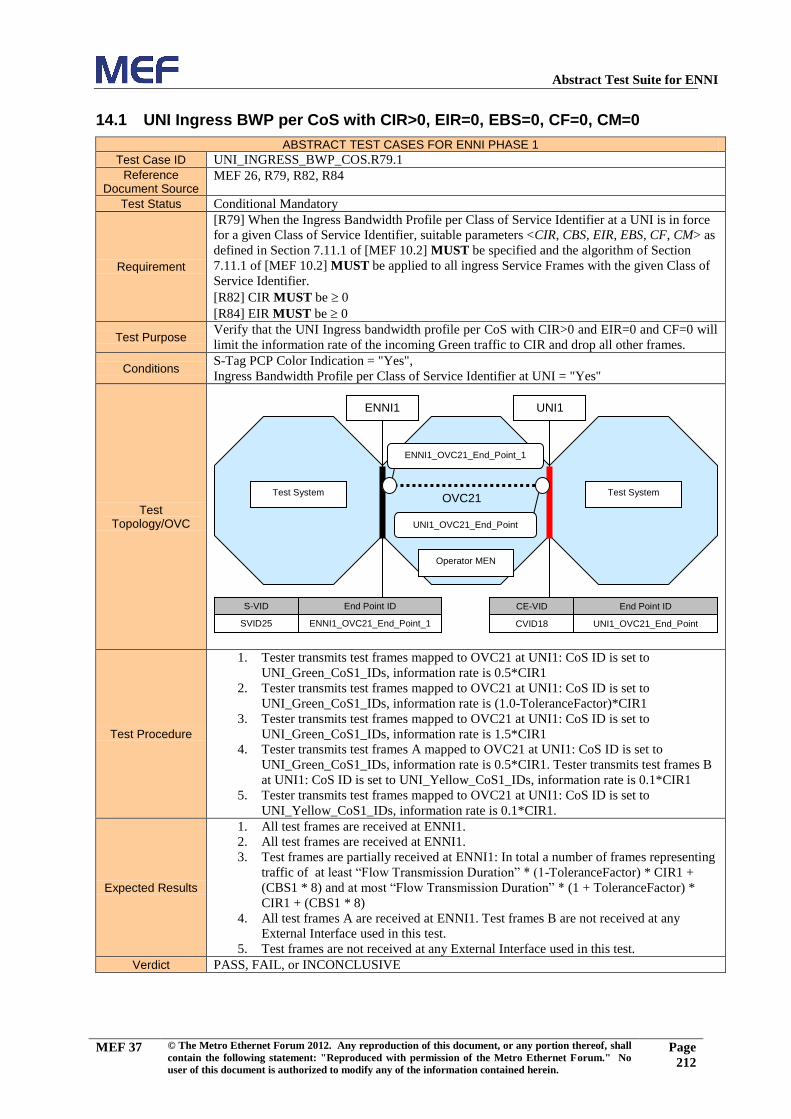
Abstract Test Suite for ENNI
MEF 37 © The Metro Ethernet Forum 2012. Any reproduction of this document, or any portion thereof, shall
contain the following statement: "Reproduced with permission of the Metro Ethernet Forum." No
user of this document is authorized to modify any of the information contained herein.
Page
212
14.1 UNI Ingress BWP per CoS with CIR>0, EIR=0, EBS=0, CF=0, CM=0
ABSTRACT TEST CASES FOR ENNI PHASE 1
Test Case ID UNI_INGRESS_BWP_COS.R79.1
Reference Document Source
MEF 26, R79, R82, R84
Test Status Conditional Mandatory
Requirement
[R79] When the Ingress Bandwidth Profile per Class of Service Identifier at a UNI is in force
for a given Class of Service Identifier, suitable parameters <CIR, CBS, EIR, EBS, CF, CM> as
defined in Section 7.11.1 of [MEF 10.2] MUST be specified and the algorithm of Section
7.11.1 of [MEF 10.2] MUST be applied to all ingress Service Frames with the given Class of
Service Identifier.
[R82] CIR MUST be 0
[R84] EIR MUST be 0
Test Purpose Verify that the UNI Ingress bandwidth profile per CoS with CIR>0 and EIR=0 and CF=0 will
limit the information rate of the incoming Green traffic to CIR and drop all other frames.
Conditions S-Tag PCP Color Indication = "Yes",
Ingress Bandwidth Profile per Class of Service Identifier at UNI = "Yes"
Test Topology/OVC
Test Procedure
1. Tester transmits test frames mapped to OVC21 at UNI1: CoS ID is set to
UNI_Green_CoS1_IDs, information rate is 0.5*CIR1
2. Tester transmits test frames mapped to OVC21 at UNI1: CoS ID is set to
UNI_Green_CoS1_IDs, information rate is (1.0-ToleranceFactor)*CIR1
3. Tester transmits test frames mapped to OVC21 at UNI1: CoS ID is set to
UNI_Green_CoS1_IDs, information rate is 1.5*CIR1
4. Tester transmits test frames A mapped to OVC21 at UNI1: CoS ID is set to
UNI_Green_CoS1_IDs, information rate is 0.5*CIR1. Tester transmits test frames B
at UNI1: CoS ID is set to UNI_Yellow_CoS1_IDs, information rate is 0.1*CIR1
5. Tester transmits test frames mapped to OVC21 at UNI1: CoS ID is set to
UNI_Yellow_CoS1_IDs, information rate is 0.1*CIR1.
Expected Results
1. All test frames are received at ENNI1.
2. All test frames are received at ENNI1.
3. Test frames are partially received at ENNI1: In total a number of frames representing
traffic of at least “Flow Transmission Duration” * (1-ToleranceFactor) * CIR1 +
(CBS1 * 8) and at most “Flow Transmission Duration” * (1 + ToleranceFactor) *
CIR1 + (CBS1 * 8)
4. All test frames A are received at ENNI1. Test frames B are not received at any
External Interface used in this test.
5. Test frames are not received at any External Interface used in this test.
Verdict PASS, FAIL, or INCONCLUSIVE
Test System
Operator MEN
S-VID End Point ID
SVID25 ENNI1_OVC21_End_Point_1
CE-VID End Point ID
CVID18 UNI1_OVC21_End_Point
UNI1
Test System
ENNI1
ENNI1_OVC21_End_Point_1
UNI1_OVC21_End_Point
OVC21
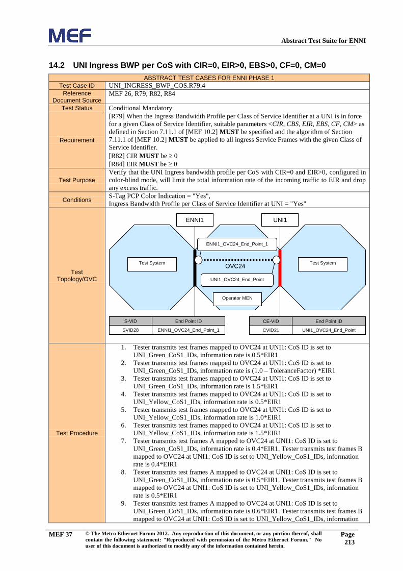
Abstract Test Suite for ENNI
MEF 37 © The Metro Ethernet Forum 2012. Any reproduction of this document, or any portion thereof, shall
contain the following statement: "Reproduced with permission of the Metro Ethernet Forum." No
user of this document is authorized to modify any of the information contained herein.
Page
213
14.2 UNI Ingress BWP per CoS with CIR=0, EIR>0, EBS>0, CF=0, CM=0
ABSTRACT TEST CASES FOR ENNI PHASE 1
Test Case ID UNI_INGRESS_BWP_COS.R79.4
Reference Document Source
MEF 26, R79, R82, R84
Test Status Conditional Mandatory
Requirement
[R79] When the Ingress Bandwidth Profile per Class of Service Identifier at a UNI is in force
for a given Class of Service Identifier, suitable parameters <CIR, CBS, EIR, EBS, CF, CM> as
defined in Section 7.11.1 of [MEF 10.2] MUST be specified and the algorithm of Section
7.11.1 of [MEF 10.2] MUST be applied to all ingress Service Frames with the given Class of
Service Identifier.
[R82] CIR MUST be 0
[R84] EIR MUST be 0
Test Purpose
Verify that the UNI Ingress bandwidth profile per CoS with CIR=0 and EIR>0, configured in
color-blind mode, will limit the total information rate of the incoming traffic to EIR and drop
any excess traffic.
Conditions S-Tag PCP Color Indication = "Yes",
Ingress Bandwidth Profile per Class of Service Identifier at UNI = "Yes"
Test Topology/OVC
Test Procedure
1. Tester transmits test frames mapped to OVC24 at UNI1: CoS ID is set to
UNI_Green_CoS1_IDs, information rate is 0.5*EIR1
2. Tester transmits test frames mapped to OVC24 at UNI1: CoS ID is set to
UNI_Green_CoS1_IDs, information rate is (1.0 – ToleranceFactor) *EIR1
3. Tester transmits test frames mapped to OVC24 at UNI1: CoS ID is set to
UNI_Green_CoS1_IDs, information rate is 1.5*EIR1
4. Tester transmits test frames mapped to OVC24 at UNI1: CoS ID is set to
UNI_Yellow_CoS1_IDs, information rate is 0.5*EIR1
5. Tester transmits test frames mapped to OVC24 at UNI1: CoS ID is set to
UNI_Yellow_CoS1_IDs, information rate is 1.0*EIR1
6. Tester transmits test frames mapped to OVC24 at UNI1: CoS ID is set to
UNI_Yellow_CoS1_IDs, information rate is 1.5*EIR1
7. Tester transmits test frames A mapped to OVC24 at UNI1: CoS ID is set to
UNI_Green_CoS1_IDs, information rate is 0.4*EIR1. Tester transmits test frames B
mapped to OVC24 at UNI1: CoS ID is set to UNI_Yellow_CoS1_IDs, information
rate is 0.4*EIR1
8. Tester transmits test frames A mapped to OVC24 at UNI1: CoS ID is set to
UNI_Green_CoS1_IDs, information rate is 0.5*EIR1. Tester transmits test frames B
mapped to OVC24 at UNI1: CoS ID is set to UNI_Yellow_CoS1_IDs, information
rate is 0.5*EIR1
9. Tester transmits test frames A mapped to OVC24 at UNI1: CoS ID is set to
UNI_Green_CoS1_IDs, information rate is 0.6*EIR1. Tester transmits test frames B
mapped to OVC24 at UNI1: CoS ID is set to UNI_Yellow_CoS1_IDs, information
Test System
Operator MEN
S-VID End Point ID
SVID28 ENNI1_OVC24_End_Point_1
CE-VID End Point ID
CVID21 UNI1_OVC24_End_Point
UNI1
Test System
ENNI1
ENNI1_OVC24_End_Point_1
UNI1_OVC24_End_Point
OVC24

Abstract Test Suite for ENNI
MEF 37 © The Metro Ethernet Forum 2012. Any reproduction of this document, or any portion thereof, shall
contain the following statement: "Reproduced with permission of the Metro Ethernet Forum." No
user of this document is authorized to modify any of the information contained herein.
Page
214
rate is 0.6*EIR1
Expected Results
1. No test frames are received at ENNI1.
2. No test frames are received at ENNI1.
3. No test frames are received at ENNI1: In total a number of frames representing
traffic larger than zero and at most “Flow Transmission Duration” * (1 +
ToleranceFactor) * EIR1 + (EBS1 * 8)
4. More than zero test frames are received at ENNI1.
5. More than zero test frames are received at ENNI1.
6. More than zero test frames are received at ENNI1.
7. No test frames A are received at ENNI1. More than zero test frames B are received at
ENNI1.
8. No test frames A are received at ENNI1. More than zero test frames B are received at
ENNI1.
9. No test frames A are received at ENNI1. More than zero test frames B are received at
ENNI1.
Verdict PASS, FAIL, or INCONCLUSIVE

Abstract Test Suite for ENNI
MEF 37 © The Metro Ethernet Forum 2012. Any reproduction of this document, or any portion thereof, shall
contain the following statement: "Reproduced with permission of the Metro Ethernet Forum." No
user of this document is authorized to modify any of the information contained herein.
Page
215
14.3 UNI Ingress BWP per CoS with CIR>0, EIR>0, CF=0, CM=0
ABSTRACT TEST CASES FOR ENNI PHASE 1
Test Case ID UNI_INGRESS_BWP_COS.R79.6
Reference Document Source
MEF 26, R79, R82, R84
Test Status Conditional Mandatory
Requirement
[R79] When the Ingress Bandwidth Profile per Class of Service Identifier at a UNI is in force
for a given Class of Service Identifier, suitable parameters <CIR, CBS, EIR, EBS, CF, CM> as
defined in Section 7.11.1 of [MEF 10.2] MUST be specified and the algorithm of Section
7.11.1 of [MEF 10.2] MUST be applied to all ingress Service Frames with the given Class of
Service Identifier.
[R82] CIR MUST be 0
[R84] EIR MUST be 0
Test Purpose
Verify that the UNI Ingress bandwidth profile per CoS with CIR>0 and EIR>0, will limit the
information rate of the incoming Green traffic to CIR, limit the sum of the excess Green
traffic and the Yellow traffic to EIR and drop any excess traffic.
Conditions S-Tag PCP Color Indication = "Yes",
Ingress Bandwidth Profile per Class of Service Identifier at UNI = "Yes"
Test Topology/OVC
Test Procedure
1. Tester transmits test frames mapped to OVC26 at UNI1: CoS ID is set to
UNI_Green_CoS1_IDs, information rate is 0.5*CIR1
2. Tester transmits test frames mapped to OVC26 at UNI1: CoS ID is set to
UNI_Green_CoS1_IDs, information rate is (1.0 - ToleranceFactor) CIR1
3. Tester transmits test frames mapped to OVC26 at UNI1: CoS ID is set to
UNI_Green_CoS1_IDs, information rate is (1.0 - ToleranceFactor) CIR1+0.5*EIR1
4. Tester transmits test frames mapped to OVC26 at UNI1: CoS ID is set to
UNI_Green_CoS1_IDs, information rate is (1.0 - ToleranceFactor) CIR1+1.0*EIR1
5. Tester transmits test frames mapped to OVC26 at UNI1: CoS ID is set to
UNI_Green_CoS1_IDs, information rate is (1.0 - ToleranceFactor) CIR1+1.5*EIR1
6. Tester transmits test frames A mapped to OVC26 at UNI1: CoS ID is set to
UNI_Green_CoS1_IDs, information rate is (1.0 - ToleranceFactor) CIR1. Tester
transmits test frames B mapped to OVC26 at UNI1: CoS ID is set to
UNI_Yellow_CoS1_IDs, information rate is (1.0 - ToleranceFactor) EIR1.
7. Tester transmits test frames A mapped to OVC26 at UNI1: CoS ID is set to
UNI_Green_CoS1_IDs, information rate is (1.0 - ToleranceFactor) CIR1+0.5*EIR1.
Tester transmits test frames B mapped to OVC26 at UNI1: CoS ID is set to
UNI_Yellow_CoS1_IDs, information rate is 0.1*EIR1.
8. Tester transmits test frames A mapped to OVC26 at UNI1: CoS ID is set to
UNI_Green_CoS1_IDs, information rate is (1.0 - ToleranceFactor) CIR1+0.5*EIR1.
Tester transmits test frames B mapped to OVC26 at UNI1: CoS ID is set to
UNI_Yellow_CoS1_IDs, information rate is 0.5*EIR1.
9. Tester transmits test frames A mapped to OVC26 at UNI1: CoS ID is set to
Test System
Operator MEN
S-VID End Point ID
SVID30 ENNI1_OVC26_End_Point_1
CE-VID End Point ID
CVID23 UNI1_OVC26_End_Point
UNI1
Test System
ENNI1
ENNI1_OVC26_End_Point_1
UNI1_OVC26_End_Point
OVC26

Abstract Test Suite for ENNI
MEF 37 © The Metro Ethernet Forum 2012. Any reproduction of this document, or any portion thereof, shall
contain the following statement: "Reproduced with permission of the Metro Ethernet Forum." No
user of this document is authorized to modify any of the information contained herein.
Page
216
UNI_Green_CoS1_IDs, information rate is (1.0 - ToleranceFactor) CIR1+0.6*EIR1.
Tester transmits test frames B mapped to OVC26 at UNI1: CoS ID is set to
UNI_Yellow_CoS1_IDs, information rate is 0.6*EIR1.
10. Tester transmits test frames A mapped to OVC26 at UNI1: CoS ID is set to
UNI_Green_CoS1_IDs, information rate is (1.0 - ToleranceFactor) CIR1+1.0*EIR1.
Tester transmits test frames B mapped to OVC26 at UNI1: CoS ID is set to
UNI_Yellow_CoS1_IDs, information rate is 0.5*EIR1.
11. Tester transmits test frames A mapped to OVC26 at UNI1: CoS ID is set to
UNI_Green_CoS1_IDs, information rate is (1.0 - ToleranceFactor) CIR1+1.5*EIR1.
Tester transmits test frames B mapped to OVC26 at UNI1: CoS ID is set to
UNI_Yellow_CoS1_IDs, information rate is 0.5*EIR1.
Expected Results
1. All test frames are received at ENNI1.
2. All test frames are received at ENNI1.
3. All test frames are received at ENNI1.
4. All test frames are received at ENNI1.
5. Test frames are partially received at ENNI1: the information rate of the received test
frames is at least (1.0 - ToleranceFactor) * CIR1.
6. All test frames A are received at ENNI1. More than zero test frames B are received at
ENNI1.
7. A number of test frames A representing traffic of least “Flow Transmission
Duration” * (1 - ToleranceFactor) * CIR1 + (CBS1 * 8)are received at ENNI1. More
than zero test frames B are received at ENNI1.
8. A number of test frames A representing traffic of least “Flow Transmission
Duration” * (1 - ToleranceFactor) * CIR1 + (CBS1 * 8)A are received at ENNI1.
More than zero test frames B are received at ENNI1.
9. A number of test frames A representing traffic of least “Flow Transmission
Duration” * (1 - ToleranceFactor) * CIR1 + (CBS1 * 8)are received at ENNI1. More
than zero test frames B are received at ENNI1.
10. A number of test frames A representing traffic of least “Flow Transmission
Duration” * (1 - ToleranceFactor) * CIR1 + (CBS1 * 8)are received at ENNI1. More
than zero test frames B are received at ENNI1.
11. A number of test frames A representing traffic of least “Flow Transmission
Duration” * (1 - ToleranceFactor) * CIR1 + (CBS1 * 8) are received at ENNI1. More
than zero test frames B are received at ENNI1.
Verdict PASS, FAIL, or INCONCLUSIVE

Abstract Test Suite for ENNI
MEF 37 © The Metro Ethernet Forum 2012. Any reproduction of this document, or any portion thereof, shall
contain the following statement: "Reproduced with permission of the Metro Ethernet Forum." No
user of this document is authorized to modify any of the information contained herein.
Page
217
14.4 UNI Ingress BWP per CoS: Commited Burst Size, EBS = 0.
ABSTRACT TEST CASES FOR ENNI PHASE 1
Test Case ID UNI_INGRESS_BWP_COS.R79.8
Reference Document Source
MEF 26, R79, R83
Test Status Conditional Mandatory
Requirement
[R79] When the Ingress Bandwidth Profile per Class of Service Identifier at a UNI is in force
for a given Class of Service Identifier, suitable parameters <CIR, CBS, EIR, EBS, CF, CM> as
defined in Section 7.11.1 of [MEF 10.2] MUST be specified and the algorithm of Section
7.11.1 of [MEF 10.2] MUST be applied to all ingress Service Frames with the given Class of
Service Identifier.
[R83] When CIR > 0, CBS MUST be greater than or equal to the largest Maximum
Transmission Unit size allowed for the ENNI Frames that the Bandwidth Profile applies to.
Test Purpose Verify that UNI Ingress bandwidth profile per CoS with CIR>0 will forward bursts of Green
traffic of at least MTU size and at most CBS size.
Conditions S-Tag PCP Color Indication = "Yes",
Ingress Bandwidth Profile per Class of Service Identifier at UNI = "Yes"
Test Topology/OVC
Test Procedure
1. Tester transmits bursts of test frames mapped to OVC21 at UNI1: CoS ID is set to
UNI_Green_CoS1_IDs, total burst size is 0.5*CBS1 octets, at a rate of 1 burst every
1 second
2. Tester transmits bursts of test frames mapped to OVC21 at UNI1: CoS ID is set to
UNI_Green_CoS1_IDs, total burst size is 1.0*CBS1 octets rounded down to the next
whole frame, at a rate of 1 burst every 1 second
3. Tester transmits bursts of test frames mapped to OVC21 at UNI1: CoS ID is set to
UNI_Green_CoS1_IDs, total burst size is (1.25*CBS1 rounded up to the nearest
whole frame) * BIR /(BIR-CIR1), at a rate of 1 burst every 1 second
4. Tester transmits bursts of test frames mapped to OVC21 at UNI1: CoS ID is set to
UNI_Green_CoS1_IDs. Perform the burst procedure described in section 17.3 in this
document)
Expected Results
1. All test frames are received at ENNI1.
2. All test frames are received at ENNI1.
3.
4. The amount of traffic received at ENNI1 is lower bound by NG and upper bound by
NG plus half of the transmitted traffic in excess of NG.All expected test frames are
received at ENNI1.
Verdict PASS, FAIL, or INCONCLUSIVE
Test System
Operator MEN
S-VID End Point ID
SVID25 ENNI1_OVC21_End_Point_1
CE-VID End Point ID
CVID18 UNI1_OVC21_End_Point
UNI1
Test System
ENNI1
ENNI1_OVC21_End_Point_1
UNI1_OVC21_End_Point
OVC21

Abstract Test Suite for ENNI
MEF 37 © The Metro Ethernet Forum 2012. Any reproduction of this document, or any portion thereof, shall
contain the following statement: "Reproduced with permission of the Metro Ethernet Forum." No
user of this document is authorized to modify any of the information contained herein.
Page
218
14.5 UNI Ingress BWP per CoS: Excess Burst Size.
ABSTRACT TEST CASES FOR ENNI PHASE 1
Test Case ID UNI_INGRESS_BWP_COS.R79.9
Reference Document Source
MEF 26, R79, R85
Test Status Conditional Mandatory
Requirement
[R79] When the Ingress Bandwidth Profile per Class of Service Identifier at a UNI is in force
for a given Class of Service Identifier, suitable parameters <CIR, CBS, EIR, EBS, CF, CM> as
defined in Section 7.11.1 of [MEF 10.2] MUST be specified and the algorithm of Section
7.11.1 of [MEF 10.2] MUST be applied to all ingress Service Frames with the given Class of
Service Identifier.
[R85] When EIR > 0, EBS MUST be greater than or equal to the largest Maximum
Transmission Unit size allowed for the ENNI Frames that the Bandwidth Profile applies to.
Test Purpose Verify that UNI Ingress bandwidth profile per CoS with CIR>0 will forward bursts of Yellow
traffic of at least MTU size and at most EBS size.
Conditions S-Tag PCP Color Indication = "Yes",
Ingress Bandwidth Profile per Class of Service Identifier at UNI = "Yes"
Test Topology/OVC
Test Procedure
1. Tester transmits bursts of test frames mapped to OVC24 at UNI1: CoS ID is set to
UNI_Yellow_CoS1_IDs, total burst size is 0.5*EBS1 octets, at a rate of 1 burst
every 1 second
2. Tester transmits bursts of test frames mapped to OVC24 at UNI1: CoS ID is set to
UNI_Yellow_CoS1_IDs, total burst size is 1.0*EBS1 octets, at a rate of 1 burst
every 1 second
3. Tester transmits bursts of test frames mapped to OVC24 test frames at UNI1: CoS ID
is set to UNI_Yellow_CoS1_IDs. Perform the burst procedure described in section
17.4 in this document.
Expected Results
1. More than zero test frames are received at ENNI1.
2. More than zero test frames are received at ENNI1.
3. All green test frames are received at ENNI1, and more than zero yellow frames are
received.
Verdict PASS, FAIL, or INCONCLUSIVE
15 Test Group: UNI Egress Bandwidth Profile per CoS
Test System
Operator MEN
S-VID End Point ID
SVID28 ENNI1_OVC24_End_Point_1
CE-VID End Point ID
CVID21 UNI1_OVC24_End_Point
UNI1
Test System
ENNI1
ENNI1_OVC24_End_Point_1
UNI1_OVC24_End_Point
OVC24

Abstract Test Suite for ENNI
MEF 37 © The Metro Ethernet Forum 2012. Any reproduction of this document, or any portion thereof, shall
contain the following statement: "Reproduced with permission of the Metro Ethernet Forum." No
user of this document is authorized to modify any of the information contained herein.
Page
219
15.1 UNI Egress BWP per CoS with CIR>0, EIR=0, EBS= 0, CF=0, CM=0
ABSTRACT TEST CASES FOR ENNI PHASE 1
Test Case ID UNI_EGRESS_BWP_COS.R81.1
Reference Document Source
MEF 26, R81, R82, R84
Test Status Conditional Mandatory
Requirement
[R81] When the Egress Bandwidth Profile per Class of Service Identifier at a UNI is in force
for a given Class of Service Identifier, suitable parameters <CIR, CBS, EIR, EBS, CF, CM>
as defined in Section 7.11.1 of [MEF 10.2] MUST be specified and when the algorithm of
Section 7.11.1 of [MEF 10.2] using these parameters is applied to these egress Service
Frames, the result for each Service Frame MUST be to declare the Service Frame either Green
or Yellow.
[R82] CIR MUST be 0
[R84] EIR MUST be 0
Test Purpose Verify that the UNI Egress bandwidth profile per CoS with CIR>0 and EIR=0 and CF=0 will
limit the information rate of the incoming Green traffic to CIR and drop all other frames.
Conditions S-Tag PCP Color Indication = "Yes",
Egress Bandwidth Profile per Class of Service Identifier at UNI = "Yes"
Test Topology/OVC
Test Procedure
1. Tester transmits test frames at ENNI1 that are mapped to OVC21: CoS ID is set to
ENNI_Green_CoS1_IDs, information rate is 0.5*CIR1
2. Tester transmits test frames at ENNI1 that are mapped to OVC21: CoS ID is set to
ENNI_Green_CoS1_IDs, information rate is 1.0*CIR1
3. Tester transmits test frames at ENNI1 that are mapped to OVC21: CoS ID is set to
ENNI_Green_CoS1_IDs, information rate is 1.5*CIR1
4. Tester transmits test frames A at ENNI1 that are mapped to OVC21: CoS ID is set to
ENNI_Green_CoS1_IDs, information rate is 0.5*CIR1. Tester transmits test frames
B at ENNI1 that are mapped to OVC21: CoS ID is set to ENNI_Yellow_CoS1_IDs,
information rate is 0.1*CIR1
5. Tester transmits test frames at ENNI1 that are mapped to OVC21: CoS ID is set to
ENNI_Yellow_CoS1_IDs, information rate is 0.1*CIR1.
Expected Results
1. All test frames are received at UNI1.
2. All test frames are received at UNI1.
3. Test frames are partially received at UNI1: the information rate of the received test
frames is at least (1.0 - ToleranceFactor) * CIR1.
4. All test frames A are received at UNI1. Test frames B are not received at any
External Interface.
5. Test frames are not received at any External Interface used in this test.
Verdict PASS, FAIL, or INCONCLUSIVE
Test System
Operator MEN
S-VID End Point ID
SVID25 ENNI1_OVC21_End_Point_1
CE-VID End Point ID
CVID18 UNI1_OVC21_End_Point
UNI1
Test System
ENNI1
ENNI1_OVC21_End_Point_1
UNI1_OVC21_End_Point
OVC21

Abstract Test Suite for ENNI
MEF 37 © The Metro Ethernet Forum 2012. Any reproduction of this document, or any portion thereof, shall
contain the following statement: "Reproduced with permission of the Metro Ethernet Forum." No
user of this document is authorized to modify any of the information contained herein.
Page
220
15.2 UNI Egress BWP per CoS with CIR=0, EIR>0, CF=0, CM=0
ABSTRACT TEST CASES FOR ENNI PHASE 1
Test Case ID UNI_EGRESS_BWP_COS.R81.4
Reference Document Source
MEF 26, R81, R82, R84
Test Status Conditional Mandatory
Requirement
[R81] When the Egress Bandwidth Profile per Class of Service Identifier at a UNI is in force
for a given Class of Service Identifier, suitable parameters <CIR, CBS, EIR, EBS, CF, CM>
as defined in Section 7.11.1 of [MEF 10.2] MUST be specified and when the algorithm of
Section 7.11.1 of [MEF 10.2] using these parameters is applied to these egress Service
Frames, the result for each Service Frame MUST be to declare the Service Frame either Green
or Yellow.
[R82] CIR MUST be 0
[R84] EIR MUST be 0
Test Purpose
Verify that the UNI Egress bandwidth profile per CoS with CIR=0 and EIR>0, configured in
color-blind mode, will limit the total information rate of the incoming traffic to EIR and drop
any excess traffic.
Conditions S-Tag PCP Color Indication = "Yes",
Egress Bandwidth Profile per Class of Service Identifier at UNI = "Yes"
Test Topology/OVC
Test Procedure
1. Tester transmits test frames at ENNI1 that are mapped to OVC24: CoS ID is set to
ENNI_Green_CoS1_IDs, information rate is 0.5*EIR1
2. Tester transmits test frames at ENNI1 that are mapped to OVC24: CoS ID is set to
ENNI_Green_CoS1_IDs, information rate is (1.0 - ToleranceFactor) * EIR1
3. Tester transmits test frames at ENNI1 that are mapped to OVC24: CoS ID is set to
ENNI_Green_CoS1_IDs, information rate is 1.5*EIR1
4. Tester transmits test frames at ENNI1 that are mapped to OVC24: CoS ID is set to
ENNI_Yellow_CoS1_IDs, information rate is 0.5*EIR1
5. Tester transmits test frames at ENNI1 that are mapped to OVC24: CoS ID is set to
ENNI_Yellow_CoS1_IDs, information rate is (1.0 - ToleranceFactor) * EIR1
6. Tester transmits test frames at ENNI1 that are mapped to OVC24: CoS ID is set to
ENNI_Yellow_CoS1_IDs, information rate is 1.5*EIR1
7. Tester transmits test frames A at ENNI1 that are mapped to OVC24: CoS ID is set to
ENNI_Green_CoS1_IDs, information rate is 0.4*EIR1. Tester transmits test frames
B at ENNI1 that are mapped to OVC24: CoS ID is set to ENNI_Yellow_CoS1_IDs,
information rate is 0.4*EIR1
8. Tester transmits test frames A at ENNI1 that are mapped to OVC24: CoS ID is set to
ENNI_Green_CoS1_IDs, information rate is 0.5*EIR1. Tester transmits test frames
B at ENNI1 that are mapped to OVC24: CoS ID is set to ENNI_Yellow_CoS1_IDs,
information rate is 0.5*EIR1
9. Tester transmits test frames A at ENNI1 that are mapped to OVC24: CoS ID is set to
ENNI_Green_CoS1_IDs, information rate is 0.6*EIR1. Tester transmits test frames
Test System
Operator MEN
S-VID End Point ID
SVID28 ENNI1_OVC24_End_Point_1
CE-VID End Point ID
CVID21 UNI1_OVC24_End_Point
UNI1
Test System
ENNI1
ENNI1_OVC24_End_Point_1
UNI1_OVC24_End_Point
OVC24

Abstract Test Suite for ENNI
MEF 37 © The Metro Ethernet Forum 2012. Any reproduction of this document, or any portion thereof, shall
contain the following statement: "Reproduced with permission of the Metro Ethernet Forum." No
user of this document is authorized to modify any of the information contained herein.
Page
221
B at ENNI1 that are mapped to OVC24: CoS ID is set to ENNI_Yellow_CoS1_IDs,
information rate is 0.6*EIR1
Expected Results
1. More than zero test frames are received at UNI1.
2. More than zero test frames are received at UNI1.
3. More than zero test frames are received at UNI1.
4. More than zero test frames are received at UNI1.
5. More than zero test frames are received at UNI1.
6. More than zero test frames are received at UNI1.
7. More than zero test frames (A + B) in an arbitrary combination are received at UNI1.
8. More than zero test frames (A + B) in an arbitrary combination are received at UNI1.
9. More than zero test frames (A + B) are received in an arbitrary combination at UNI1.
Verdict PASS, FAIL, or INCONCLUSIVE

Abstract Test Suite for ENNI
MEF 37 © The Metro Ethernet Forum 2012. Any reproduction of this document, or any portion thereof, shall
contain the following statement: "Reproduced with permission of the Metro Ethernet Forum." No
user of this document is authorized to modify any of the information contained herein.
Page
222
15.3 UNI Egress BWP per CoS with CIR>0, EIR>0, CF=0
ABSTRACT TEST CASES FOR ENNI PHASE 1
Test Case ID UNI_EGRESS_BWP_COS.R81.6
Reference Document Source
MEF 26, R81, R82, R84
Test Status Conditional Mandatory
Requirement
[R81] When the Egress Bandwidth Profile per Class of Service Identifier at a UNI is in force
for a given Class of Service Identifier, suitable parameters <CIR, CBS, EIR, EBS, CF, CM>
as defined in Section 7.11.1 of [MEF 10.2] MUST be specified and when the algorithm of
Section 7.11.1 of [MEF 10.2] using these parameters is applied to these egress Service
Frames, the result for each Service Frame MUST be to declare the Service Frame either Green
or Yellow.
[R82] CIR MUST be 0
[R84] EIR MUST be 0
Test Purpose
Verify that the UNI Egress bandwidth profile per CoS with CIR>0 and EIR>0, will limit the
information rate of the incoming Green traffic to CIR, limit the sum of the excess Green
traffic and the Yellow traffic to EIR and drop any excess traffic.
Conditions S-Tag PCP Color Indication = "Yes",
Egress Bandwidth Profile per Class of Service Identifier at UNI = "Yes"
Test Topology/OVC
Test Procedure
1. Tester transmits test frames at ENNI1 that are mapped to OVC26: CoS ID is set to
ENNI_Green_CoS1_IDs, information rate is 0.5*CIR1
2. Tester transmits test frames at ENNI1 that are mapped to OVC26: CoS ID is set to
ENNI_Green_CoS1_IDs, information rate is (1.0 - ToleranceFactor) CIR1
3. Tester transmits test frames at ENNI1 that are mapped to OVC26: CoS ID is set to
ENNI_Green_CoS1_IDs, information rate is (1.0 - ToleranceFactor) CIR1+0.5*EIR1
4. Tester transmits test frames at ENNI1 that are mapped to OVC26: CoS ID is set to
ENNI_Green_CoS1_IDs, information rate is (1.0 - ToleranceFactor) CIR1+1.0*EIR1
5. Tester transmits test frames at ENNI1 that are mapped to OVC26: CoS ID is set to
ENNI_Green_CoS1_IDs, information rate is (1.0 - ToleranceFactor) CIR1+1.5*EIR1
6. Tester transmits test frames A at ENNI1 that are mapped to OVC26: CoS ID is set to
ENNI_Green_CoS1_IDs, information rate is (1.0 - ToleranceFactor) CIR1. Tester
transmits test frames B at ENNI1 that are mapped to OVC26: CoS ID is set to
ENNI_Yellow_CoS1_IDs, information rate is (1.0 - ToleranceFactor) EIR1.
7. Tester transmits test frames A at ENNI1 that are mapped to OVC26: CoS ID is set to
ENNI_Green_CoS1_IDs, information rate is (1.0 - ToleranceFactor)
CIR1+0.5*EIR1. Tester transmits test frames B at ENNI1 that are mapped to
OVC26: CoS ID is set to ENNI_Yellow_CoS1_IDs, information rate is 0.1*EIR1.
8. Tester transmits test frames A at ENNI1 that are mapped to OVC26: CoS ID is set to
ENNI_Green_CoS1_IDs, information rate is (1.0 - ToleranceFactor)
CIR1+0.5*EIR1. Tester transmits test frames B at ENNI1 that are mapped to
OVC26: CoS ID is set to ENNI_Yellow_CoS1_IDs, information rate is 0.5*EIR1.
Test System
Operator MEN
S-VID End Point ID
SVID30 ENNI1_OVC26_End_Point_1
CE-VID End Point ID
CVID23 UNI1_OVC26_End_Point
UNI1
Test System
ENNI1
ENNI1_OVC26_End_Point_1
UNI1_OVC26_End_Point
OVC26

Abstract Test Suite for ENNI
MEF 37 © The Metro Ethernet Forum 2012. Any reproduction of this document, or any portion thereof, shall
contain the following statement: "Reproduced with permission of the Metro Ethernet Forum." No
user of this document is authorized to modify any of the information contained herein.
Page
223
9. Tester transmits test frames A at ENNI1 that are mapped to OVC26: CoS ID is set to
ENNI_Green_CoS1_IDs, information rate is (1.0 - ToleranceFactor)
CIR1+0.6*EIR1. Tester transmits test frames B at ENNI1 that are mapped to
OVC26: CoS ID is set to ENNI_Yellow_CoS1_IDs, information rate is 0.6*EIR1.
10. Tester transmits test frames A at ENNI1 that are mapped to OVC26: CoS ID is set to
ENNI_Green_CoS1_IDs, information rate is (1.0 - ToleranceFactor)
CIR1+1.0*EIR1. Tester transmits test frames A at ENNI1 that are mapped to
OVC26: CoS ID is set to ENNI_Yellow_CoS1_IDs, information rate is 0.5*EIR1.
11. Tester transmits test frames A at ENNI1 that are mapped to OVC26: CoS ID is set to
ENNI_Green_CoS1_IDs, information rate is (1.0 - ToleranceFactor)
CIR1+1.5*EIR1. Tester transmits test frames B at ENNI1 that are mapped to
OVC26: CoS ID is set to ENNI_Yellow_CoS1_IDs, information rate is 0.5*EIR1.
Expected Results
1. All test frames are received at UNI1.
2. All test frames are received at UNI1.
3. All test frames are received at UNI1.
4. All test frames are received at UNI1.
5. Test frames are partially received at UNI1: the information rate of the received test
frames is at least (1.0 - ToleranceFactor) * CIR1.
6. All test frames A are received at UNI1. More than zero test frames B are received at
UNI1.
7. A number of test frames A representing traffic of least “Flow Transmission
Duration” * (1 - ToleranceFactor) * CIR1 + (CBS1 * 8)are received at UNI1. More
than zero test frames B are received at UNI1.
8. A number of test frames A representing traffic of least “Flow Transmission
Duration” * (1 - ToleranceFactor) * CIR1 + (CBS1 * 8) are received at UNI1. More
than zero test frames B are received at UNI1.
9. A number of test frames A representing traffic of least “Flow Transmission
Duration” * (1 - ToleranceFactor) * CIR1 + (CBS1 * 8) are received at UNI1. More
than zero test frames B are received at UNI1.
10. A number of test frames A representing traffic of least “Flow Transmission
Duration” * (1 - ToleranceFactor) * CIR1 + (CBS1 * 8)are received at UNI1. More
than zero test frames B are received at UNI1.
11. A number of test frames A representing traffic of least “Flow Transmission
Duration” * (1 - ToleranceFactor) * CIR1 + (CBS1 * 8)are received at UNI1. More
than zero test frames B are received at UNI1.
Verdict PASS, FAIL, or INCONCLUSIVE

Abstract Test Suite for ENNI
MEF 37 © The Metro Ethernet Forum 2012. Any reproduction of this document, or any portion thereof, shall
contain the following statement: "Reproduced with permission of the Metro Ethernet Forum." No
user of this document is authorized to modify any of the information contained herein.
Page
224
15.4 UNI Egress BWP per CoS: Commited Burst Size, EBS = 0
ABSTRACT TEST CASES FOR ENNI PHASE 1
Test Case ID UNI_EGRESS_BWP_COS.R81.8
Reference Document Source
MEF 26, R81, R83
Test Status Conditional Mandatory
Requirement
[R81] When the Egress Bandwidth Profile per Class of Service Identifier at a UNI is in force
for a given Class of Service Identifier, suitable parameters <CIR, CBS, EIR, EBS, CF, CM>
as defined in Section 7.11.1 of [MEF 10.2] MUST be specified and when the algorithm of
Section 7.11.1 of [MEF 10.2] using these parameters is applied to these egress Service
Frames, the result for each Service Frame MUST be to declare the Service Frame either Green
or Yellow.
[R83] When CIR > 0, CBS MUST be greater than or equal to the largest Maximum
Transmission Unit size allowed for the ENNI Frames that the Bandwidth Profile applies to.
Test Purpose Verify that UNI Egress bandwidth profile per CoS with CIR>0 will forward bursts of Green
traffic of at least MTU size and at most CBS size.
Conditions S-Tag PCP Color Indication = "Yes",
Egress Bandwidth Profile per Class of Service Identifier at UNI = "Yes"
Test Topology/OVC
Test Procedure
1. Tester transmits bursts of test frames at ENNI1 that are mapped to OVC21: CoS ID
is set to ENNI_Green_CoS1_IDs, total burst size is 0.5*CBS1 octets, at a rate of 1
burst every 1 second
2. Tester transmits bursts of test frames at ENNI1 that are mapped to OVC21: CoS ID
is set to ENNI_Green_CoS1_IDs, total burst size is 1.0*CBS1 octets rounded down
to the next whole frame, at a rate of 1 burst every 1 second
3. Tester transmits bursts of test frames at ENNI1 that are mapped to OVC21CoS ID is
set to ENNI_Green_CoS1_IDs, total burst size is (1.25*CBS1 rounded up to the
nearest whole frame) * BIR /(BIR-CIR1), at a rate of 1 burst every 1 second
4. Tester transmits bursts of test frames at ENNI1 that are mapped to OVC21: CoS ID
is set to ENNI_Green_CoS1_IDs. Perform the burst described in section 17.3 in this
document.
Expected Results
1. All test frames are received at UNI1.
2. All test frames are received at UNI1.
3. The amount of traffic received at ENNI1 is lower bound by NG and upper bound by
NG plus half of the transmitted traffic in excess of NG.
4. All expected test frames are received at UNI1.
Verdict PASS, FAIL, or INCONCLUSIVE
Test System
Operator MEN
S-VID End Point ID
SVID25 ENNI1_OVC21_End_Point_1
CE-VID End Point ID
CVID18 UNI1_OVC21_End_Point
UNI1
Test System
ENNI1
ENNI1_OVC21_End_Point_1
UNI1_OVC21_End_Point
OVC21

Abstract Test Suite for ENNI
MEF 37 © The Metro Ethernet Forum 2012. Any reproduction of this document, or any portion thereof, shall
contain the following statement: "Reproduced with permission of the Metro Ethernet Forum." No
user of this document is authorized to modify any of the information contained herein.
Page
225
15.5 UNI Egress BWP per CoS: Excess Burst Size
ABSTRACT TEST CASES FOR ENNI PHASE 1
Test Case ID UNI_EGRESS_BWP_COS.R81.9
Reference Document Source
MEF 26, R81, R85
Test Status Conditional Mandatory
Requirement
[R81] When the Egress Bandwidth Profile per Class of Service Identifier at a UNI is in force
for a given Class of Service Identifier, suitable parameters <CIR, CBS, EIR, EBS, CF, CM>
as defined in Section 7.11.1 of [MEF 10.2] MUST be specified and when the algorithm of
Section 7.11.1 of [MEF 10.2] using these parameters is applied to these egress Service
Frames, the result for each Service Frame MUST be to declare the Service Frame either Green
or Yellow.
[R85] When EIR > 0, EBS MUST be greater than or equal to the largest Maximum
Transmission Unit size allowed for the ENNI Frames that the Bandwidth Profile applies to.
Test Purpose Verify that UNI Egress bandwidth profile per CoS with CIR>0 will forward bursts of Yellow
traffic of at least MTU size and at most EBS size.
Conditions S-Tag PCP Color Indication = "Yes",
Egress Bandwidth Profile per Class of Service Identifier at UNI = "Yes"
Test Topology/OVC
Test Procedure
1. Tester transmits bursts of test frames at ENNI1 that are mapped to OVC24: CoS ID
is set to ENNI_Yellow_CoS1_IDs, total burst size is 0.5*EBS1 octets, at a rate of 1
burst every 1 second
2. Tester transmits bursts of test frames at ENNI1 that are mapped to OVC24: CoS ID
is set to ENNI_Yellow_CoS1_IDs, total burst size is 1.0*EBS1octets, at a rate of 1
burst every 1 second
3. Tester transmits bursts of test frames at ENNI1 that are mapped to OVC24: CoS ID
is set to ENNI_Yellow_CoS1_IDs. Perform the burst procedure described in section
17.4 in this document.
Expected Results
1. More than zero test frames are received at UNI1.
2. More than zero test frames are received at UNI1.
3. All expected green test frames are received at UNI1, and more than zero yellow
frames are received.
Verdict PASS, FAIL, or INCONCLUSIVE
Test System
Operator MEN
S-VID End Point ID
SVID28 ENNI1_OVC24_End_Point_1
CE-VID End Point ID
CVID21 UNI1_OVC24_End_Point
UNI1
Test System
ENNI1
ENNI1_OVC24_End_Point_1
UNI1_OVC24_End_Point
OVC24

Abstract Test Suite for ENNI
MEF 37 © The Metro Ethernet Forum 2012. Any reproduction of this document, or any portion thereof, shall
contain the following statement: "Reproduced with permission of the Metro Ethernet Forum." No
user of this document is authorized to modify any of the information contained herein.
Page
226
16 References
[MEF 26] External Network Network (ENNI) – Phase 1, including MEF26.0.1 and
MEF26.0.2 updates
[MEF 12.1] Carrier Ethernet Network Architecture Framework, Part 2: Ethernet Services
Layer - Base Elements
[802.3 – 2005] IEEE 802.3 – 2005 Information technology – Telecommunications and
information exchange between systems – Local and metropolitan area networks – Specific
requirements – Part 3: Carrier sense multiple access with collision detection (CSMA/CD)
access method and physical layer specifications, 8 December 2005.
[802.1ad – 2005] IEEE 802.1ad – 2005 IEEE Standard for Local and metropolitan Area
Networks – Virtual Bridged Local Area Networks Amendment 4: Provider Bridges, May
2005.
[MEF 10.2] Ethernet Services Attributes Phase 2, MEF 10.2
[MEF 9] Abstract Test Suite for Ethernet Services at the UNI, MEF 9
[MEF 6.1] Ethernet Services Definitions - Phase 2, MEF 6.1
[RFC 2119] "Key words for use in RFCs to Indicate Requirement Levels", S. Bradner,
http://www.ietf.org/rfc/rfc2119.txt (Normative)
[RFC 2285] "Benchmarking Terminology for LAN Switching Devices", R. Mandeville, http://www.ietf.org/rfc/rfc2285.txt [MEF 23] Carrier Ethernet Class of Service – Phase 1, MEF 23
[MEF 17] Service OAM Requirements & Framework – Phase 1, MEF 17
[ISO9646] OSI Conformance testing methodology and framework, ISO/IEC 9646-1
[802.1ag – 2007] IEEE Standard for Local and metropolitan Area Net-works – Virtual
Bridged Local Area Networks Amendment 5: Connectivity Fault Management, December
2007, IEEE Std 802.1ag – 2007
[RFC 2544] Benchmarking Methodology for Network Interconnect Devices, S. Bradner, J.
McQuaid, http://www.ietf.org/rfc/rfc2544.txt
[RFC 2889] Benchmarking Methodology for LAN Switching Devices, R. Mandeville, J.
Perser, http://www.ietf.org/rfc/rfc2889.txt
17 Appendix

Abstract Test Suite for ENNI
MEF 37 © The Metro Ethernet Forum 2012. Any reproduction of this document, or any portion thereof, shall
contain the following statement: "Reproduced with permission of the Metro Ethernet Forum." No
user of this document is authorized to modify any of the information contained herein.
Page
227
17.1 Table of Requirements Derived from the ENNI Specification
The test cases in this document are derived from the requirements of the MEF 26
specification ([MEF 26]). Not every requirement specified in the [MEF 26] can be translated
into test cases, for example, as, some requirements specify contractual obligations. Such
requirements are marked in the table below as not applicable. The table also represents a
creation status of conformance test cases for that requirement ("Done", or "Planned"). The
"Done" status means, that at least one test case is fully specified for the requirement. The
"Planned" status means the requirement is applicable, and there are no test cases specified yet
for that requirement. The creation status and type are only meaningful if the requirement is
applicable.
The Abstract Test Suite for ENNI is split in to two parts: Level 1 and Level 2 ATS. The
column ATS Part identifies the mapping of the requirement to the ENNI ATS part and the
test group. This document includes test cases of Level 1 ATS only.
Table 133: Table of requirements
Req. ID
Requirement
Applicable
Creation Status
ATS Part/ATS Group
R1 When there are two physical links in the ENNI, an ENNI-Ni
MUST be capable of implementing Link Aggregation as in
Clause 43.6.1 of [802.3 – 2005] with one Link Aggregation
Group (LAG) across the ports supporting an instance of
ENNI and with one link in active mode and the other in
standby mode.
Yes Done Level 1/
Protection
R2 When Link Aggregation is used at the ENNI, LACP MUST
be used by each ENNI-Ni per [802.3 – 2005]. Yes Done
Level 1/
Protection
R3 The Operator ENNI Identifier MUST be unique among all
such identifiers for ENNIs supported by the Operator MEN. No Done N/A
R4 The Operator ENNI Identifier MUST contain no more than
45 bytes. No Done N/A
R5 Each link in an ENNI MUST be one of the following physical
layers in full duplex mode as defined in [IEEE 802.3 – 2005]:
1000Base-SX, 1000Base-LX, 1000Base T, 10GBASE-SR,
10GBASE-LX4, 10GBASE-LR, 10GBASE-ER, 10GBASE-
SW, 10GBASE-LW, 10GBASE-EW.
Yes Done Level 1/
Foundation
R6 Each ENNI Frame MUST have the standard Ethernet format
with one of the tag configurations specified in Table 3 of
[MEF 26]. [DA = Destination Address, SA = Source Address,
ET = Ethertype/Length, S-Tag with Tag Protocol
Identification Field (TPID) = 0x88A8, C-Tag with TPID =
0x8100.]
Yes Done Level 1/
Foundation
R7 An S-Tag MUST have the format specified in Sections 9.5
and 9.7 of [IEEE 802.1ad]. Yes Done
Level 1/
Foundation
R8 A C-Tag MUST have the format specified in Sections 9.5 and
9.6 of [IEEE 802.1ad]. Yes Done
Level 1/
Foundation
R9 An ingress ENNI Frame that is invalid as defined in Clause
3.4 of [802.3 – 2005] MUST be discarded by the receiving
Operator MEN.
Yes Done Level 1/
Foundation
R10 An ingress ENNI Frame whose length is less than 64 octets
MUST be discarded by the receiving Operator MEN as per
Clause 4.2.4.2.2 of [802.3 – 2005].
Yes Done Level 1/
Foundation
R11 If the Number of Links is one, then the Protection Mechanism
attribute MUST be set to "none." No Done N/A

Abstract Test Suite for ENNI
MEF 37 © The Metro Ethernet Forum 2012. Any reproduction of this document, or any portion thereof, shall
contain the following statement: "Reproduced with permission of the Metro Ethernet Forum." No
user of this document is authorized to modify any of the information contained herein.
Page
228
Req. ID
Requirement
Applicable
Creation Status
ATS Part/ATS Group
R12 If the Number of Links is 2 and LAG as specified in [R1] is
implemented, then the Protection Mechanism attribute MUST
be set to "Link Aggregation."
No Done N/A
R13 If the conditions specified [R11] and [R12] are not met, then
the Protection Mechanism attribute MUST be set to "other." No Done N/A
R14 The ENNI Maximum Transmission Unit Size MUST be at
least 1526 bytes. Yes Done
Level 1/
Foundation
D1 The ENNI Maximum Transmission Unit Size SHOULD be at
least 2000 bytes. Yes Done
Level 2/
Optional
Requiremetns
R15 When an ENNI Frame is larger than the MTU, the receiving
Operator MEN for this frame MUST discard it, and the frame
may or may not be ignored in the operation of a Bandwidth
Profile that applies to this ENNI Frame.
Yes Done Level 1/
Foundation
R16 For a given S-Tagged ENNI Frame, the End Point to which it
is mapped MUST be determined by the S-VLAN ID value in
the S-Tag.
Yes Done Level 1/
Foundation
R17 An S-VLAN ID value MUST be used in no more than one
row of the map. Yes Done
Level 1/
Foundation
R18 The End Point Type MUST be OVC End Point. No Done N/A
R19 An ingress S-Tagged ENNI Frame that is not mapped to an
existing End Point MUST NOT be forwarded to an External
Interface by the receiving Operator MEN.
Yes Done Level 1/
Foundation
R20 An ENNI Frame without an S-Tag MUST NOT be mapped to
an OVC End Point. Yes Done
Level 1/
Foundation
R21 Consider the OVC that associates an OVC End Point where
more than one S-VLAN ID value map to the OVC End Point
in the End Point Map. This OVC MUST have its S-VLAN ID
Preservation attribute set to Yes. (See Section 7.2.12 of [MEF
26].)
Yes Done Level 2/
Bundling
R22 Consider the OVC that associates an OVC End Point where
more than one S-VLAN ID value map to the OVC End Point
in the End Point Map. This OVC MUST have its CE-VLAN
ID Preservation attribute set to Yes. (See Section 7.2.10 of 0.)
Yes Done Level 2/
Bundling
R23 Consider the OVC that associates an OVC End Point where
more than one S-VLAN ID value map to the OVC End Point
in the End Point Map. This OVC MUST have its CE-VLAN
CoS Preservation attribute set to Yes. (See Section 7.2.11 of
0.)
Yes Done Level 2/
Bundling
R24 Consider the OVC that associates an OVC End Point where
more than one S-VLAN ID value map to the OVC End Point
in the End Point Map. The OVC End Points associated by this
OVC MUST be at an ENNI.
Yes Done Level 2/
Bundling
R25 Consider the OVC that associates an OVC End Point where
more than one S-VLAN ID value map to the OVC End Point
in the End Point Map. This OVC MUST associate exactly
two OVC End Points.
Yes Done Level 2/
Bundling
R26 Consider the OVC that associates an OVC End Point where
more than one S-VLAN ID value map to the OVC End Point
in the End Point Map. Each End Point Map at the other
ENNIs where there is an OVC End Point associated by this
OVC MUST map the same list of S-VLAN ID values to the
OVC End Point associated by the OVC.
Yes Done Level 2/
Bundling

Abstract Test Suite for ENNI
MEF 37 © The Metro Ethernet Forum 2012. Any reproduction of this document, or any portion thereof, shall
contain the following statement: "Reproduced with permission of the Metro Ethernet Forum." No
user of this document is authorized to modify any of the information contained herein.
Page
229
Req. ID
Requirement
Applicable
Creation Status
ATS Part/ATS Group
R27 A given OVC MUST associate at most one OVC End Point at
a given UNI. Yes Done
Level 1/
Foundation
O1 A given OVC MAY associate more than one OVC End Point
at a given ENNI. Yes Done
Level 2/
Optional
Requiremetns
R28 If an egress frame mapped to an OVC End Point results from
an ingress frame mapped to an OVC End Point, there MUST
be an OVC that associates the two OVC End Points. And, the
two OVC End Points MUST be different from each other.
Yes Done Level 1/
Foundation
R29 At least one of the OVC End Points in an OVC MUST be at
an ENNI . Yes Done
Level 1/
Foundation
R30 The OVC Identifier MUST be unique among all such
identifiers for OVCs supported by the Operator MEN. No Done N/A
R31 The OVC Identifier MUST contain no more than 45 bytes. No Done N/A
R32 The OVC Maximum Transmission Unit Size MUST be at
least 1526 bytes. Yes Done
Level 1/
Foundation
D2 The OVC Maximum Transmission Unit Size SHOULD be at
least 2000 bytes. Yes Done
Level 2/
Optional
Requiremetns
R33 When an ENNI Frame or a Service Frame is larger than the
OVC MTU Size for the OVC associating the OVC End Point
to which it is mapped, the receiving Operator for this frame
MUST discard it, and the operation of a Bandwidth Profile
that applies to this frame is not defined.
Yes Done Level 1/
Foundation
R34 The OVC Maximum Transmission Unit Size MUST be less
than or equal to the MTU Size of each UNI where an OVC
End Point exists that is associated by the OVC.
Yes Done Level 1/
Foundation
R35 When an OVC has the CE-VLAN ID Preservation attribute
with a value of Yes and all of the UNIs with an OVC End
Point associated by the OVC are such that all CE-VLAN IDs
map to the OVC End Point (see Section 7.5.2 of 0), then the
relationship between the format of the frame at the ingress
External Interface and the corresponding frame at the egress
External Interface MUST be as specified in Table 5 of 0.
Yes Done
Level 1/ CE-
VLAN ID
Preservation
R36 When an OVC has the CE-VLAN ID Preservation attribute
with a value of Yes and not all of the UNIs with an OVC End
Point associated by the OVC are such that all CE-VLAN IDs
map to the OVC End Point (see Section 7.5.2 of 0), then the
relationships between the format of the frame at the ingress
External Interface and the corresponding frame at the egress
External Interface MUST be as specified in Table 6 of 0.
Yes Done
Level 1/ CE-
VLAN ID
Preservation
R37 When an OVC has the CE-VLAN ID Preservation attribute
with a value of Yes and none of the End Points associated by
the OVC are at UNIs, then the relationships between the
format of the frame at the ingress ENNI and the
corresponding frame at the egress ENNI MUST be as
specified in Table 7 of 0.
Yes Done
Level 1/ CE-
VLAN ID
Preservation
R38 When an OVC has the CE-VLAN CoS Preservation attribute
with a value of Yes the relationship between the format of the
frame at the ingress External Interface and the corresponding
frame at the egress External Interface MUST be as specified
in Table 8 of 0.
Yes Done
Level 1/ CE-
VLAN CoS
Preservation
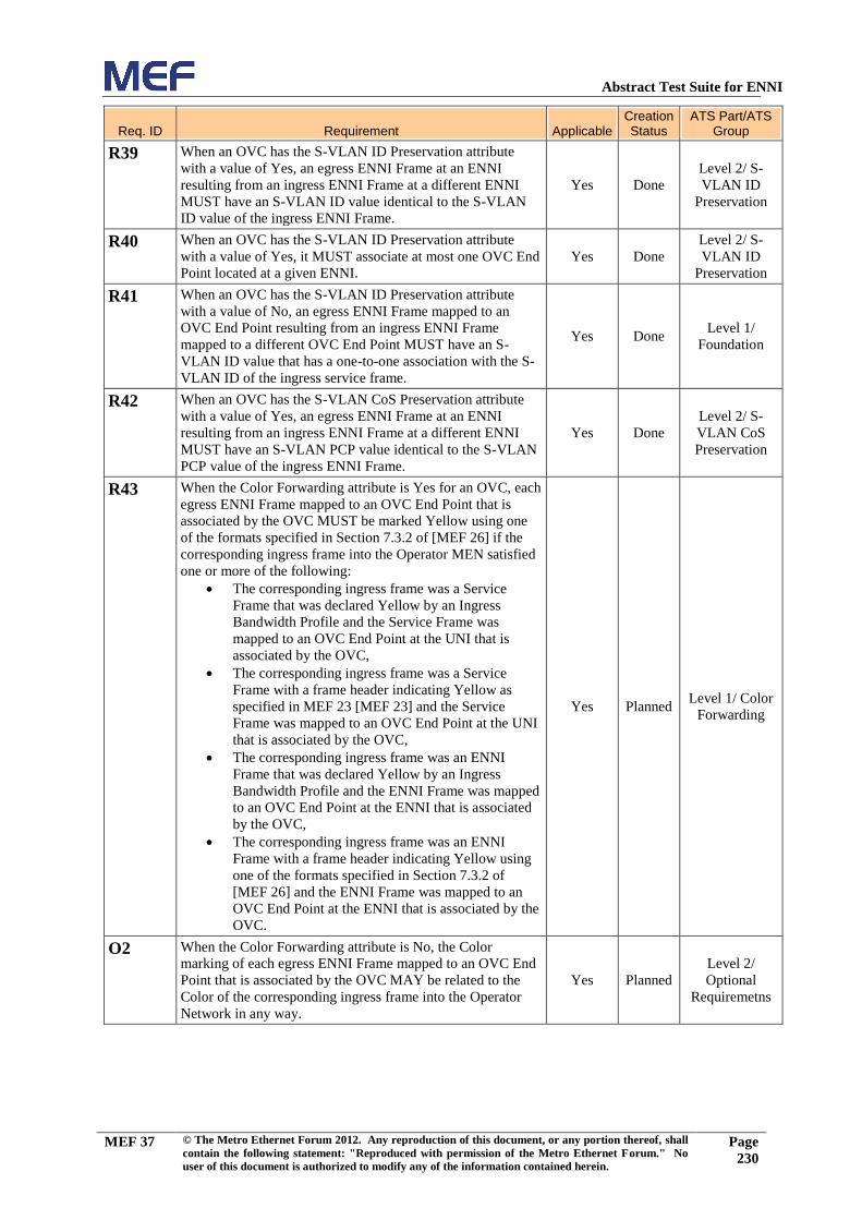
Abstract Test Suite for ENNI
MEF 37 © The Metro Ethernet Forum 2012. Any reproduction of this document, or any portion thereof, shall
contain the following statement: "Reproduced with permission of the Metro Ethernet Forum." No
user of this document is authorized to modify any of the information contained herein.
Page
230
Req. ID
Requirement
Applicable
Creation Status
ATS Part/ATS Group
R39 When an OVC has the S-VLAN ID Preservation attribute
with a value of Yes, an egress ENNI Frame at an ENNI
resulting from an ingress ENNI Frame at a different ENNI
MUST have an S-VLAN ID value identical to the S-VLAN
ID value of the ingress ENNI Frame.
Yes Done
Level 2/ S-
VLAN ID
Preservation
R40 When an OVC has the S-VLAN ID Preservation attribute
with a value of Yes, it MUST associate at most one OVC End
Point located at a given ENNI.
Yes Done
Level 2/ S-
VLAN ID
Preservation
R41 When an OVC has the S-VLAN ID Preservation attribute
with a value of No, an egress ENNI Frame mapped to an
OVC End Point resulting from an ingress ENNI Frame
mapped to a different OVC End Point MUST have an S-
VLAN ID value that has a one-to-one association with the S-
VLAN ID of the ingress service frame.
Yes Done Level 1/
Foundation
R42 When an OVC has the S-VLAN CoS Preservation attribute
with a value of Yes, an egress ENNI Frame at an ENNI
resulting from an ingress ENNI Frame at a different ENNI
MUST have an S-VLAN PCP value identical to the S-VLAN
PCP value of the ingress ENNI Frame.
Yes Done
Level 2/ S-
VLAN CoS
Preservation
R43 When the Color Forwarding attribute is Yes for an OVC, each
egress ENNI Frame mapped to an OVC End Point that is
associated by the OVC MUST be marked Yellow using one
of the formats specified in Section 7.3.2 of [MEF 26] if the
corresponding ingress frame into the Operator MEN satisfied
one or more of the following:
The corresponding ingress frame was a Service
Frame that was declared Yellow by an Ingress
Bandwidth Profile and the Service Frame was
mapped to an OVC End Point at the UNI that is
associated by the OVC,
The corresponding ingress frame was a Service
Frame with a frame header indicating Yellow as
specified in MEF 23 [MEF 23] and the Service
Frame was mapped to an OVC End Point at the UNI
that is associated by the OVC,
The corresponding ingress frame was an ENNI
Frame that was declared Yellow by an Ingress
Bandwidth Profile and the ENNI Frame was mapped
to an OVC End Point at the ENNI that is associated
by the OVC,
The corresponding ingress frame was an ENNI
Frame with a frame header indicating Yellow using
one of the formats specified in Section 7.3.2 of
[MEF 26] and the ENNI Frame was mapped to an
OVC End Point at the ENNI that is associated by the
OVC.
Yes Planned Level 1/ Color
Forwarding
O2 When the Color Forwarding attribute is No, the Color
marking of each egress ENNI Frame mapped to an OVC End
Point that is associated by the OVC MAY be related to the
Color of the corresponding ingress frame into the Operator
Network in any way.
Yes Planned
Level 2/
Optional
Requiremetns

Abstract Test Suite for ENNI
MEF 37 © The Metro Ethernet Forum 2012. Any reproduction of this document, or any portion thereof, shall
contain the following statement: "Reproduced with permission of the Metro Ethernet Forum." No
user of this document is authorized to modify any of the information contained herein.
Page
231
Req. ID
Requirement
Applicable
Creation Status
ATS Part/ATS Group
R44 When the Unicast Frame Delivery is "unconditional," all
properly formatted ingress frames mapped to an OVC End
Point at an External Interface with a unicast destination MAC
address MUST be delivered to all of the other OVC End
Points in the OVC.
NOTE: The MEF26 editors clarified each R44 and R45 are
conditional requirements by themselves.
Yes Done Level 1/
Foundation
R45 When the Unicast Frame Delivery is "conditional," a properly
formatted ingress frame mapped to an OVC End Point at an
External Interface with a unicast destination MAC address is
delivered to all or a subset of all of the other OVC End Points
in the OVC depending on certain conditions being met. When
"conditional" is in force, the conditions for delivery MUST be
specified.
NOTE This requirement is not testable due to lack of specific
conditions specified in MEF26. This is a service
specification/configuration issue.
Yes Done Level 1/
Foundation
R46 When the Multicast Frame Delivery is "unconditional," all
properly formatted ingress frames mapped to an OVC End
Point at an External Interface with a multicast destination
MAC address MUST be delivered to all of the other End
Points associated by the OVC.
Yes Done Level 1/
Foundation
R47 When the Multicast Frame Delivery is "conditional," a
properly formatted ingress frame mapped to an OVC End
Point at an External Interface with a multicast destination
MAC address is delivered to all or a subset of all of the other
OVC End Points associated by the OVC depending on certain
conditions being met. When "conditional" is in force, the
conditions for delivery MUST be specified.
Yes Done Level 1/
Foundation
R48 When the Broadcast Frame Delivery is "unconditional," all
properly formatted ingress frames mapped to an OVC End
Point at an External Interface with the broadcast destination
MAC address MUST be delivered to all of the other OVC
End Points associated by the OVC.
Yes Done Level 1/
Foundation
R49 When the Broadcast Frame Delivery is "conditional," a
properly formatted ingress frame mapped to an OVC End
Point at an External Interface with the broadcast destination
MAC address is delivered to all or a subset of all of the other
OVC End Points associated by the OVC depending on certain
conditions being met. When "conditional" is in force, the
conditions for delivery MUST be specified.
Yes Done Level 1/
Foundation
R50 The OVC End Point Identifier MUST be unique among all
such identifiers for OVC End Points supported by the
Operator MEN.
No Done N/A
R51 The OVC End Point Identifier MUST contain no more than
45 bytes. No Done N/A
R52 For each OVC End Point at an ENNI, each possible S-Tag
PCP value MUST be included in exactly one Class of Service
Identifier.
Yes Planned
Level 1/ Class
of Service
Identifier
O3 One of the Class of Service Identifiers MAY indicate 100%
discard. Yes Planned
Level 2/
Optional
Requiremetns

Abstract Test Suite for ENNI
MEF 37 © The Metro Ethernet Forum 2012. Any reproduction of this document, or any portion thereof, shall
contain the following statement: "Reproduced with permission of the Metro Ethernet Forum." No
user of this document is authorized to modify any of the information contained herein.
Page
232
Req. ID
Requirement
Applicable
Creation Status
ATS Part/ATS Group
R53 At a given ENNI, all OVC End Points associated by the same
OVC MUST have the same Class of Service Identifiers.
NOTE: This requirement is applicable for n > 1 OVC End
Points at a given ENNI in the case of hairpin switching as
covered in O1.
Yes Planned
Level 2/
Optional
Requirements
D3 An Operator MEN SHOULD support the use of different
Class of Service Identifiers attributes for OVC End Points at
an ENNI that are associated by different OVCs.
Yes Planned
Level 2/
Optional
Requiremetns
R54 Color indication for each ENNI Frame MUST conform to
requirements [R3] and [R4] of MEF 23 [MEF 23]. Yes Planned
Level 1/ Class
of Service
Identifier
R55 If the S-Tag PCP field is used to indicate Color for the ENNI
Frame, then the Class of Services attribute MUST map S-Tag
PCP values to L, M, and H as per [R8] of MEF 23 [MEF 23].
Yes Planned
Level 1/ Class
of Service
Identifier
R56 If the DEI bit is used to indicate Color for the ENNI Frame,
then the Class of Services attribute MUST map S-Tag PCP
values to L, M, and H as per [R9] of MEF 23 [MEF 23].
Yes Planned
Level 1/ Class
of Service
Identifier
R57 When the Ingress Bandwidth Profile per OVC End Point is in
force for a given OVC End Point, suitable parameters <CIR,
CBS, EIR, EBS, CF, CM> as defined in Section 7.6.1 of 0
MUST be specified and the algorithm of Section 7.6.1 of 0
MUST be applied to all ingress ENNI Frames that are
mapped to the given OVC End Point.
Yes Planned
Level 2 / ENNI
Ingress OVC
End Point
Bandwidth
Profile
R58 The Color Mode for the Bandwidth Profile Algorithm MUST
be color-aware.
Yes Planned
Level 2 / ENNI
Ingress OVC
End Point
Bandwidth
Profile
R59 When the Egress Bandwidth Profile per OVC End Point is in
force for a given OVC End Point, suitable parameters <CIR,
CBS, EIR, EBS, CF, CM> as defined in Section 7.6.1 of 0
MUST be specified and all egress ENNI Frames mapped to
the given OVC End Point MUST have the property defined in
7.6.3 of 0.
Yes Planned
Level 2 / ENNI
Egress OVC
End Point
Bandwidth
Profile
R60 The Color Mode for the Bandwidth Profile Algorithm MUST
be color-aware.
Yes Planned
Level 2 / ENNI
Egress OVC
End Point
Bandwidth
Profile
R61 When the Ingress Bandwidth Profile per Class of Service
Identifier is in force for a given ENNI Class of Service
Identifier, suitable parameters <CIR, CBS, EIR, EBS, CF,
CM> as defined in Section 7.6.1 of [MEF26] MUST be
specified and the algorithm of Section 7.6.1 of [MEF26]
MUST be applied to all ingress ENNI Frames mapped to the
OVC End Point that have the given ENNI Class of Service
Identifier.
Yes Planned
Level 1 / ENNI
Ingress CoS
Bandwidth
Profile
R62 The Bandwidth Profile Algorithm MUST be color-aware.
Yes Planned
Level 1 / ENNI
Ingress CoS
Bandwidth
Profile

Abstract Test Suite for ENNI
MEF 37 © The Metro Ethernet Forum 2012. Any reproduction of this document, or any portion thereof, shall
contain the following statement: "Reproduced with permission of the Metro Ethernet Forum." No
user of this document is authorized to modify any of the information contained herein.
Page
233
Req. ID
Requirement
Applicable
Creation Status
ATS Part/ATS Group
R63 When the Egress Bandwidth Profile per Class of Service
Identifier is in force for a given ENNI Class of Service
Identifier, suitable parameters <CIR, CBS, EIR, EBS, CF,
CM> as defined in Section 7.6.1 of 0 MUST be specified and
all egress ENNI Frames mapped to the OVC End Point with
the given Class of Service Identifier MUST have the property
defined in Section 7.6.3 of 0.
Yes Planned
Level 1 / ENNI
Egress CoS
Bandwidth
Profile
R64 The Color Mode for the Bandwidth Profile Algorithm MUST
be color-aware. Yes Planned
Level 1 / ENNI
Egress CoS
Bandwidth
Profile
R65 The UNI OVC Identifier MUST be the concatenation of the
UNI Identifier and the OVC Identifier. No Done N/A
R66 The OVC End Point at the UNI for a Service Frame MUST
be identified by the value of CE-VLAN ID of the Service
Frame.
Yes Done Level 1/
Foundation
R67 An ingress Service Frame that is not mapped to an existing
OVC End Point or EVC at the UNI MUST be discarded. Yes Done
Level 1/
Foundation
O4 Multiple CE-VLAN IDs MAY map to a single OVC End
Point. Yes Done
Level 2/
Optional
Requiremetns
R68 Each CE-VLAN ID MUST have one of the following
mutually exclusive properties; 1) it maps to one OVC End
Point, 2) it maps to one EVC that associates UNIs within the
Operator MEN, 3) it does not map to either such an EVC or
an OVC End Point.
Yes Done Level 1/
Foundation
R69 When an OVC associating the OVC End Point to which the
CE-VLAN ID for untagged and priority tagged Service
Frames is mapped does not have the CE-VLAN ID
Preservation attribute in force, egress Service Frames for this
OVC End Point at the given UNI MUST be untagged.
Yes Done Level 1/
Foundation
R70 There MUST be three mutually exclusive ways to determine
the Class of Service Identifier from the content of a given
Service Frame at UNI as described in Sections 7.5.3.1,
7.5.3.2, and 7.5.3.3 of 0.
This requirement is meant to explain that there ARE three
mutually exclusive ways to determine the CoS ID available.
It is not mentioned to mandate the support of all three for any
MEF26-compliant implementation. This requirement is not
testable.
Yes Done Level 1/
Foundation
R71 When the Class of Service Identifier is based on OVC End
Point, all ingress Data Service Frames mapped to the same
OVC End Point at the UNI MUST have the same Class of
Service Identifier.
Yes Done Level 1/
Foundation
R72 The Class of Service Identifier for an ingress Data Service
Frame at the UNI MUST be determined by the OVC End
Point and non-overlapping sets of values of the PCP field in
the C-Tag.
Yes Done Level 1/
Foundation
R73 If the ingress frame does not contain a C-Tag, it MUST have
the same Class of Service Identifier as an ingress frame with
Priority Code Point field = 0 in the C-Tag.
Yes Done Level 1/
Foundation
R74 The union of the sets of PCP field values MUST contain all of
the possible values.
NOTE: Not testable by this ATS.
No Done N/A

Abstract Test Suite for ENNI
MEF 37 © The Metro Ethernet Forum 2012. Any reproduction of this document, or any portion thereof, shall
contain the following statement: "Reproduced with permission of the Metro Ethernet Forum." No
user of this document is authorized to modify any of the information contained herein.
Page
234
Req. ID
Requirement
Applicable
Creation Status
ATS Part/ATS Group
R75 The Class of Service Identifier for an ingress Data Service
Frame at the UNI containing an IP packet MUST be
determined by the OVC End Point and non-overlapping sets
of values of the DSCP.
Yes Done Level 1/
Foundation
R76 The union of the sets of DSCP values MUST contain all of
the possible DSCP values.
NOTE: Not testable by this ATS.
No Done N/A
R77 Each ingress Data Service Frame at the UNI not containing an
IP packet and mapped to a given OVC End Point MUST have
the same Class of Service Identifier with a value agreed upon
by the Operator and the Service Provider.
Yes Done Level 1/
Foundation
R78 When the Ingress Bandwidth Profile per OVC End Point at a
UNI is in force for a given OVC End Point, suitable
parameters <CIR, CBS, EIR, EBS, CF, CM> as defined in
Section 7.11.1 of [MEF 10.2] MUST be specified and the
algorithm of Section 7.11.1 of [MEF 10.2] MUST be applied
to all ingress ENNI Frames that are mapped to the given OVC
End Point.
Yes Planned
Level 2 / UNI
Ingress OVC
End Point
Bandwidth
Profile
R79 When the Ingress Bandwidth Profile per Class of Service
Identifier at a UNI is in force for a given Class of Service
Identifier, suitable parameters <CIR, CBS, EIR, EBS, CF,
CM> as defined in Section 7.11.1 of [MEF 10.2] MUST be
specified and the algorithm of Section 7.11.1 of [MEF 10.2]
MUST be applied to all ingress ENNI Frames with the given
Class of Service Identifier.
Yes Planned
Level 1 / UNI
Ingress CoS
Bandwidth
Profile
R80 When the Egress Bandwidth Profile per OVC End Point at a
UNI is in force for a given OVC End Point, suitable
parameters <CIR, CBS, EIR, EBS, CF, CM> as defined in
Section 7.11.1 of [MEF 10.2] MUST be specified and when
the algorithm of Section 7.11.1 of [MEF 10.2] using these
parameters is applied to these egress Service Frames, the
result for each Service Frame MUST be to declare the Service
Frame either Green or Yellow.
Yes Planned
Level 2 / UNI
Egress OVC
End Point
Bandwidth
Profile
R81 When the Egress Bandwidth Profile per Class of Service
Identifier at a UNI is in force for a given Class of Service
Identifier, suitable parameters <CIR, CBS, EIR, EBS, CF,
CM> as defined in Section 7.11.1 of [MEF 10.2] MUST be
specified and when the algorithm of Section 7.11.1 of [MEF
10.2] using these parameters is applied to these egress Service
Frames, the result for each Service Frame MUST be to
declare the Service Frame either Green or Yellow.
Yes Planned
Level 1 / UNI
Egress CoS
Bandwidth
Profile

Abstract Test Suite for ENNI
MEF 37 © The Metro Ethernet Forum 2012. Any reproduction of this document, or any portion thereof, shall
contain the following statement: "Reproduced with permission of the Metro Ethernet Forum." No
user of this document is authorized to modify any of the information contained herein.
Page
235
Req. ID
Requirement
Applicable
Creation Status
ATS Part/ATS Group
R82 CIR MUST be 0.
Yes Planned
Level 1 / ENNI
Ingress CoS
Bandwidth
Profile, ENNI
Egress CoS
Bandwidth
Profile
Level 2 / ENNI
Ingress OVC
End Point
Bandwidth
Profile, ENNI
Egress OVC
End Point
Bandwidth
Profile
R83 When CIR > 0, CBS MUST be greater than or equal to the
largest Maximum Transmission Unit size allowed for the
ENNI Frames that the Bandwidth Profile applies to.
Yes Planned
Level 1 / ENNI
Ingress CoS
Bandwidth
Profile, ENNI
Egress CoS
Bandwidth
Profile
Level 2 / ENNI
Ingress OVC
End Point
Bandwidth
Profile, ENNI
Egress OVC
End Point
Bandwidth
Profile
R84 EIR MUST be 0.
Yes Planned
Level 1 / ENNI
Ingress CoS
Bandwidth
Profile, ENNI
Egress CoS
Bandwidth
Profile
Level 2 / ENNI
Ingress OVC
End Point
Bandwidth
Profile, ENNI
Egress OVC
End Point
Bandwidth
Profile

Abstract Test Suite for ENNI
MEF 37 © The Metro Ethernet Forum 2012. Any reproduction of this document, or any portion thereof, shall
contain the following statement: "Reproduced with permission of the Metro Ethernet Forum." No
user of this document is authorized to modify any of the information contained herein.
Page
236
Req. ID
Requirement
Applicable
Creation Status
ATS Part/ATS Group
R85 When EIR > 0, EBS MUST be greater than or equal to the
largest Maximum Transmission Unit size allowed for the
ENNI Frames that the Bandwidth Profile applies to.
Yes Planned
Level 1 / ENNI
Ingress CoS
Bandwidth
Profile, ENNI
Egress CoS
Bandwidth
Profile
Level 2 / ENNI
Ingress OVC
End Point
Bandwidth
Profile, ENNI
Egress OVC
End Point
Bandwidth
Profile
R86 For a sequence of ENNI Frames, with arrival times at the
reference point and lengths , the level of compliance color
assigned to each ENNI Frame MUST be defined according to
the algorithm in Figure 10.
Yes Planned
Level 1 / ENNI
Ingress CoS
Bandwidth
Profile
Level 2 / ENNI
Ingress OVC
End Point
Bandwidth
Profile
O5 Multiple models of Ingress Bandwidth Profile application
MAY exist simultaneously at an ENNI. Yes Planned
Level 2/
Optional
Requiremetns
R87 An ENNI MUST be configured such that at most a single
Ingress Bandwidth Profile applies to any given ingress ENNI
Frame.
Yes Planned
Level 1 / ENNI
Ingress CoS
Bandwidth
Profile
Level 2 / ENNI
Ingress OVC
End Point
Bandwidth
Profile
R88 The disposition of each ENNI Frame for delivery to each
egress External Interface MUST be as described in Table 11
of 0.
Yes Planned
Level 1 / ENNI
Ingress CoS
Bandwidth
Profile
Level 2 / ENNI
Ingress OVC
End Point
Bandwidth
Profile
R89 When a sequence of egress ENNI Frames with arrival times
and lengths at the ENNI, are subjected to an Egress
Bandwidth Profile with parameters <CIR, CBS, EIR, EBS,
CF, CM>, the result of applying the algorithm of Section
7.6.1 of 0 to these frames MUST be to declare each ENNI
Frame either Green or Yellow.
Yes Planned
Level 1 / ENNI
Egress CoS
Bandwidth
Profile
Level 2 / ENNI
Egress OVC
End Point
Bandwidth
Profile

Abstract Test Suite for ENNI
MEF 37 © The Metro Ethernet Forum 2012. Any reproduction of this document, or any portion thereof, shall
contain the following statement: "Reproduced with permission of the Metro Ethernet Forum." No
user of this document is authorized to modify any of the information contained herein.
Page
237
Req. ID
Requirement
Applicable
Creation Status
ATS Part/ATS Group
O6 Multiple models of Egress Bandwidth Profile application
MAY exist simultaneously for an egress ENNI. Yes Planned
Level 2/
Optional
Requiremetns
R90 However, an egress ENNI Frame MUST be subject to at most
one Egress Bandwidth Profile.
Yes Planned
Level 1 / ENNI
Egress CoS
Bandwidth
Profile
Level 2 / ENNI
Egress OVC
End Point
Bandwidth
Profile
R91 For each physical link in the ENNI, an ENNI-N MUST be
capable of supporting Active DTE mode capabilities as
specified in clause 57.2.9 of IEEE 802.3 [802.3 – 2005].
Yes Planned Level 2/ Link
OAM
R92 For each physical link in the ENNI, an ENNI-N MUST be
capable of supporting Passive DTE mode capabilities as
specified in clause 57.2.9 of IEEE 802.3 [802.3 – 2005].
Yes Planned Level 2/ Link
OAM
D4 When Link OAM is enabled on an ENNI-N, the loopback
capability SHOULD be disabled. Yes Planned
Level 2/ Link
OAM
D5 When Link OAM is enabled on an ENNI-N, it SHOULD not
advertise its loopback capability, as defined in Section
57.2.11 of IEEE 802.3ah, during the discovery phase if
Loopback is not enabled.
Yes Planned Level 2/ Link
OAM
D6 The ENNI MTU size SHOULD be greater or equal to the
MTU size of :
Each EVC MTU size crossing the ENNI plus 4 bytes
(to accommodate the potential addition, at the ENNI,
of an S-TAG), and
Each OVC which has an OVC End Point at this
ENNI.
Yes Done
Level 2/
Optional
Requiremetns
R93 The OVC MTU size MUST be greater or equal to the EVC
MTU size of each EVC supported by this OVC plus 4 bytes
(to accommodate the potential addition, at the ENNI, of an S-
TAG).
Yes Done Level 1/
Foundation
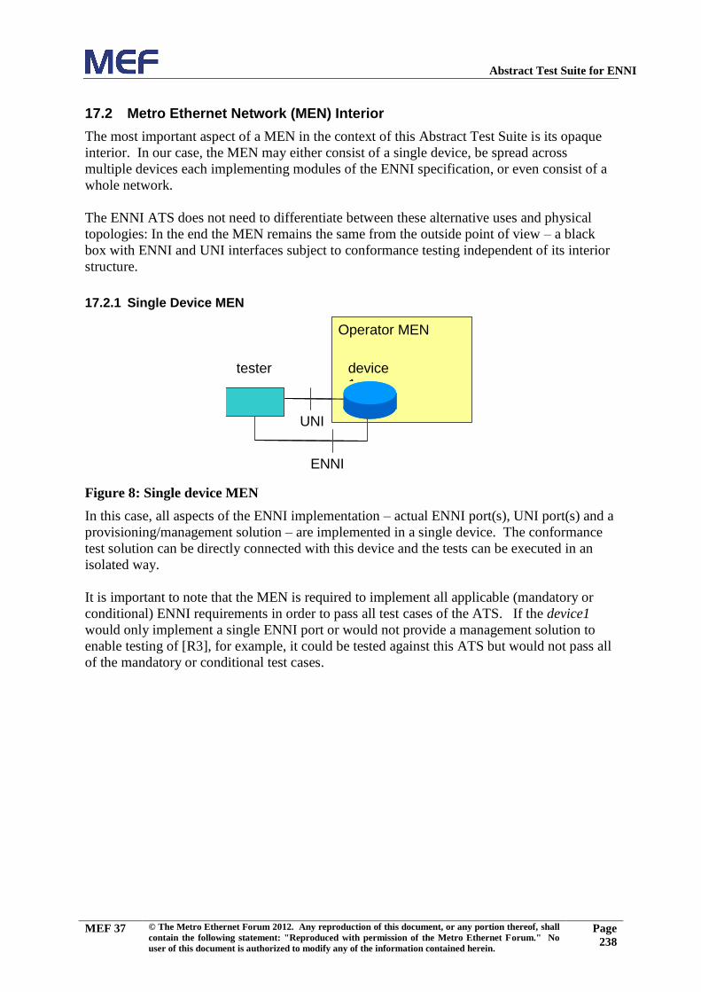
Abstract Test Suite for ENNI
MEF 37 © The Metro Ethernet Forum 2012. Any reproduction of this document, or any portion thereof, shall
contain the following statement: "Reproduced with permission of the Metro Ethernet Forum." No
user of this document is authorized to modify any of the information contained herein.
Page
238
17.2 Metro Ethernet Network (MEN) Interior
The most important aspect of a MEN in the context of this Abstract Test Suite is its opaque
interior. In our case, the MEN may either consist of a single device, be spread across
multiple devices each implementing modules of the ENNI specification, or even consist of a
whole network.
The ENNI ATS does not need to differentiate between these alternative uses and physical
topologies: In the end the MEN remains the same from the outside point of view – a black
box with ENNI and UNI interfaces subject to conformance testing independent of its interior
structure.
17.2.1 Single Device MEN
device1
tester
Operator MEN (SUT)
device1
UNI
ENNI
Operator MEN
Figure 8: Single device MEN
In this case, all aspects of the ENNI implementation – actual ENNI port(s), UNI port(s) and a
provisioning/management solution – are implemented in a single device. The conformance
test solution can be directly connected with this device and the tests can be executed in an
isolated way.
It is important to note that the MEN is required to implement all applicable (mandatory or
conditional) ENNI requirements in order to pass all test cases of the ATS. If the device1
would only implement a single ENNI port or would not provide a management solution to
enable testing of [R3], for example, it could be tested against this ATS but would not pass all
of the mandatory or conditional test cases.
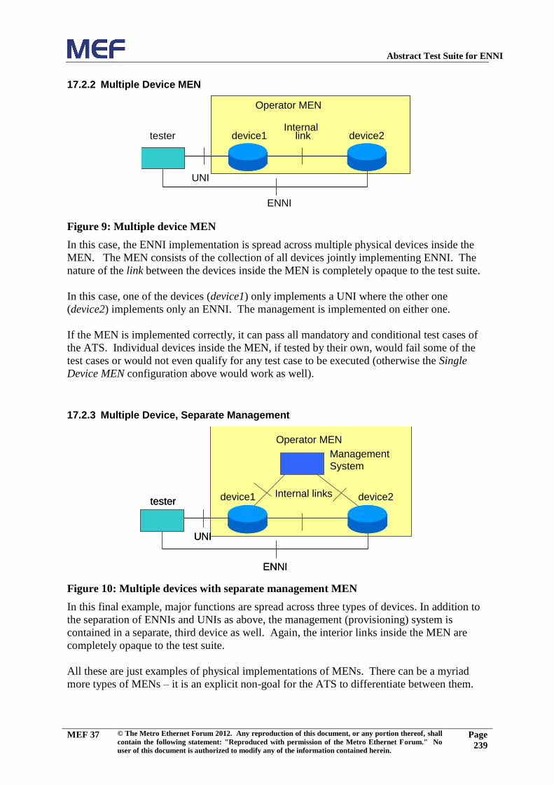
Abstract Test Suite for ENNI
MEF 37 © The Metro Ethernet Forum 2012. Any reproduction of this document, or any portion thereof, shall
contain the following statement: "Reproduced with permission of the Metro Ethernet Forum." No
user of this document is authorized to modify any of the information contained herein.
Page
239
17.2.2 Multiple Device MEN
device1
device2
UNI
Internal ETH lin
k
Operator MEN (SUT)
device1 device2 tester
ENNI
Internal ETH link
Operator MEN (SUT)
Figure 9: Multiple device MEN
In this case, the ENNI implementation is spread across multiple physical devices inside the
MEN. The MEN consists of the collection of all devices jointly implementing ENNI. The
nature of the link between the devices inside the MEN is completely opaque to the test suite.
In this case, one of the devices (device1) only implements a UNI where the other one
(device2) implements only an ENNI. The management is implemented on either one.
If the MEN is implemented correctly, it can pass all mandatory and conditional test cases of
the ATS. Individual devices inside the MEN, if tested by their own, would fail some of the
test cases or would not even qualify for any test case to be executed (otherwise the Single
Device MEN configuration above would work as well).
17.2.3 Multiple Device, Separate Management
device1 device2 tester
UNI
ENNI
Internal ETH link
Management System
Operator MEN (SUT)
device1 device2 tester
UNI
ENNI
Internal links
Management System
Operator MEN
Figure 10: Multiple devices with separate management MEN
In this final example, major functions are spread across three types of devices. In addition to
the separation of ENNIs and UNIs as above, the management (provisioning) system is
contained in a separate, third device as well. Again, the interior links inside the MEN are
completely opaque to the test suite.
All these are just examples of physical implementations of MENs. There can be a myriad
more types of MENs – it is an explicit non-goal for the ATS to differentiate between them.

Abstract Test Suite for ENNI
MEF 37 © The Metro Ethernet Forum 2012. Any reproduction of this document, or any portion thereof, shall
contain the following statement: "Reproduced with permission of the Metro Ethernet Forum." No
user of this document is authorized to modify any of the information contained herein.
Page
240
17.2.4 Vendor vs. Service Provider Testing
Any of the structures above qualify for service provider testing as well as for vendor testing.
Sometimes it seems to be common sense that service provider infrastructure testing must be
large and complex whereas vendors would only submit a single device to a conformance test.
This assumption is wrong with ENNI. As seen above, there are good reasons why vendors
might sometimes want to submit an MEN with ENNI functionality consisting of multiple
devices to a test. On the other hand, a service provider could pass network conformance
testing with a "Single Device" MEN configuration as above, given a suitable implementation.
Whether the result of a single-device service provider test is useful is beyond the scope of this
ATS and needs to be decided by the user (recipient) of the conformance test results.

Abstract Test Suite for ENNI
MEF 37 © The Metro Ethernet Forum 2012. Any reproduction of this document, or any portion thereof, shall
contain the following statement: "Reproduced with permission of the Metro Ethernet Forum." No
user of this document is authorized to modify any of the information contained herein.
Page
241

Abstract Test Suite for ENNI
MEF 37 © The Metro Ethernet Forum 2012. Any reproduction of this document, or any portion thereof, shall
contain the following statement: "Reproduced with permission of the Metro Ethernet Forum." No
user of this document is authorized to modify any of the information contained herein.
Page
242
17.3 CBS Test Procedure
This test procedure has been modeled following ITU-T Y.1564, Appendix I.2 (with
stricter parameters suited to a conformance test scenario). It is applicable for a color-
aware or non-color-aware service with CBS > 0. The variable names in this appendix
reference variables in section 5.
1. The transmitter turns off for the minimum time necessary to fill the token bucketto or
greater than 102% * CBS1*8/CIR1 to initialize the measurement with the Bc CBS
Token Bucket full and has overflown by an amount equal to or greater than 2% *
CBS1.
2. Then the transmitter bursts the largest number of back-to-back (minimum interframe
gap) frames that will draw down the number of remaining bytes in the Bc Token
Bucket to more than or equal to the greatest of5:
a. 0.5% of CBS1
b. 0.5 times ENNI_MTU
c. The lesser of (25%*CBS1) and (0.0003 s *CIR1/8)
(After the last frame of the burst, the transmitter turns off for the smallest amount of
time necessary to refill the CBS Token Bucket to at least 50% full. Then the
transmitter resumes non-bursty transmission at the CIR1. Frames should be
transmitted at constant intervals, e.g. without burstiness or interval variation. The
period T is defined to end when the total number of frames transmitted during the
period is 10 times the number of frames transmitted during the burst. The transmitter
continues to cycle the frame bursting over successive periods of T in this sequence
starting from step 1 until the FlowTransmissionDuration time as defined in section
5.4.8 has passed.
3. Measure the received frames upon egress at the other end of the network. All green
frames shall be received.
5 Note: These numbers represent a tolerance margin for token bucket implementations such that the token
bucket is never completely emptied during the test procedure.

Abstract Test Suite for ENNI
MEF 37 © The Metro Ethernet Forum 2012. Any reproduction of this document, or any portion thereof, shall
contain the following statement: "Reproduced with permission of the Metro Ethernet Forum." No
user of this document is authorized to modify any of the information contained herein.
Page
243
17.4 EBS Test Procedure
This test procedure has been modeled following ITU-T Y.1564, Appendix I.3 (with
stricter parameters suited to a conformance test scenario). It is applicable for a color-
aware service with CIR > 0 and EBS > 0.
In this test there will be two test flows, the first for the Green/CBS test flow and the
second for the Yellow/EBS test flow.
The green cycle has a period of nominal length TG, and the yellow cycle has a period
of nominal length TY both defined later. The green cycle and the yellow cycle run
asynchronously with each other.
1. The green frame transmitter turns off for the minimum time necessary to fill the token
bucket to or greater than 102% * (CBS*8/CIR) to initialize the measurement with the
Bc Token Bucket full and has overflown by at least 2 % * CBS.
At the same time, the yellow frame transmitter turns off for the time equal to or
greater than 102% * (EBS*8/EIR) to initialize the measurement with the Be Token
Bucket full and has overflown by at least 2 % * EBS.
2. Then the transmitter bursts the largest number of green frames that will draw down
the number of remaining bytes in the Bc Token Bucket, to more than or equal to the
greatest of6:
a. 0.5% of the CBS1
b. 0.5 times ENNI_MTU
c. The lesser of (25%*CBS1) and (0.0003 s *CIR1/8)
Likewise, the transmitter bursts the largest number of yellow frames that will draw
down the number of remaining bytes in the Be Token Bucket to more than or equal to
the greatest of:
a. 0.5% of the EBS1
b. 0.5 times ENNI_MTU
c. The lesser of (25%*EBS1) and (0.0003*EIR1/8)
After the last frame of the green frame burst, the transmitter stops transmitting green
frames for the smallest amount of time necessary to refill the CBS Token Bucket to
at least 50% full. Likewise, after the last frame of the yellow frame burst, the
transmitter stops transmitting yellow frames for the smallest amount of time
necessary to refill the EBS Token Bucket to at least 50% full. Then the transmitter
resumes non-bursty green and yellow frame transmission at the CIR1 and EIR1 for
the rest of the periods TG and TY, respectively. Each period is defined to end when
the total number of frames transmitted during that period is 10 times the number of
frames transmitted during the burst. At the end of each period, the cycle is repeated
from the beginning of this step 1 until the FlowTransmissionDuration time as defined
in section 5.4.8 has passed.
6 Note: These numbers represent a tolerance margin for token bucket implementations such that the token
bucket is never completely emptied during the test procedure.

Abstract Test Suite for ENNI
MEF 37 © The Metro Ethernet Forum 2012. Any reproduction of this document, or any portion thereof, shall
contain the following statement: "Reproduced with permission of the Metro Ethernet Forum." No
user of this document is authorized to modify any of the information contained herein.
Page
244
3. Measure the green-colored frames, the yellow-colored frames and the total combined
information rate upon egress at the other end of the network. All green frames shall be
received, and more than zero yellow frames shall be received.
NOTE: The intent of this test procedure is not to test for the yellow portion of the
bandwidth profile; it is only testing whether the implementation allows yellow traffic
to get through at all.
Further Notes (not part of the test procedure):
Note that the bursting may include periods of burst green frames only, burst yellow
frames only, burst green – burst yellow frames combined, and burst frames from one
cycle transmitted during EIR- or CIR-spaced frames from the other cycle. When a
burst frame competes for a transmission time with a spaced frame, the burst frame
shall take precedence if it is the first frame in the burst. If a later frame of the burst
competes with an EIR- or CIR-spaced frame for transmission, then the timing of the
spaced frame shall take precedence, and the burst frame shall wait in queue.
Note that burst frames from one cycle may be transmitted freely at line rate in the
spaced period of the frames from the other cycle transmitting at CIR or EIR. When
burst frames of both cycles compete for the transmitter, the transmitter may be shared
on a pro-rata basis between the bursts, or one burst may be served with preference
while the other stream waits its turn for bursting while continuing to be served at EIR
or CIR. During non-burst periods, if a green frame transmitted at CIR competes for a
transmit time with a yellow frame transmitted at EIR, then the green CIR frame shall
be transmitted at the proper time while the yellow frame is queued. Green CIR
frames may be transmitted during the idle time between yellow frames transmitted at
EIR, and yellow EIR frames may be transmitted during the idle time between green
frames transmitted at CIR.