eniq tgr discussion document
TRANSCRIPT

Institute for Energy and Transport
Luca Gandossi
EUR 25199 EN – 2012
ENIQ TGR DISCUSSION DOCUMENT
Risk-Informed In-Service Inspection:An Overview for the Non-Specialist
ENIQ report No 46

The mission of the JRC-IE is to provide support to Community policies related to both nuclear and non-nuclear energy in order to ensure sustainable, secure and efficient energy production, distribution and use. European Commission Joint Research Centre Institute for Energy and Transport Contact information Address: Westerduinweg 3, NL-1755 LE Petten E-mail: [email protected] Tel.: +31.224.565250 Fax: +31.224.565641 http://iet.jrc.ec.europa.eu/ http://ec.europa.eu/dgs/jrc/index.cfm Legal Notice Neither the European Commission nor any person acting on behalf of the Commission is responsible for the use which might be made of this publication.
Europe Direct is a service to help you find answers to your questions about the European Union
Freephone number (*):
00 800 6 7 8 9 10 11
(*) Certain mobile telephone operators do not allow access to 00 800 numbers or these calls may be billed.
A great deal of additional information on the European Union is available on the Internet. It can be accessed through the Europa server http://europa.eu/ JRC68676 EUR 25199 EN ISBN 978-92-79-23017-2 ISSN 1831-9424 doi:10.2790/42657 Luxembourg: Publications Office of the European Union, 2012 © European Union, 2012 Reproduction is authorised provided the source is acknowledged Printed in The Netherlands.
European Commission Directorate General Joint Research Centre Institute for Energy and Transport Petten, The Netherlands
ENIQ TGR DISCUSSION DOCUMENT
RISK-INFORMED IN-SERVICE INSPECTION:
AN OVERVIEW FOR THE NON-SPECIALIST
April 2012 ENIQ Report nr. 46 EUR 25199 EN

ENIQ, the European Network for Inspection and Qualification, publishes three types of documents: Type 1 — Consensus documents Consensus documents contain harmonised principles, methods, approaches and procedures and emphasize the degree of harmonisation between ENIQ members. Type 2 — Position/Discussion documents Position/discussion documents contain compilations of ideas, express opinions, review practices, draw conclusions and make recommendations for technical projects. Type 3 — Technical reports Technical reports contain results of investigations, compilations of data, reviews and procedures without expressing any specific opinion or evaluation on behalf of ENIQ. This 'ENIQ TGR Discussion Document – Risk-Informed In-Service Inspection: An Overview for the Non-Specialist' (ENIQ Report No 46) is a type 2 document.

5
FOREWORD The present work is the outcome of the activities of the ENIQ Task Group on Risk (TGR). ENIQ, the European Network for Inspection and Qualification, was set up in 1992 in recognition of the importance of the issue of qualification of NDE inspection procedures used in in-service inspection programmes for nuclear power plants. Driven by European nuclear utilities and managed by the European Commission Joint Research Centre (JRC) in Petten, the Netherlands, ENIQ was intended to be a network in which available resources and expertise could be managed at European level. It was also recognised that harmonisation in the field of codes and standards for inspection qualification would be a major advantage for all parties involved, and would ultimately increase the safety of European nuclear power plants. More information on the ENIQ network and its activities can be found at http://safelife.jrc.ec.europa.eu/eniq/. ENIQ activities are carried out by two sub-groups: the Task Group on Qualification (TGQ) focuses on the qualification of in-service inspection (ISI) systems, and the Task Group on Risk (TGR) focuses on risk-informed in-service inspection (RI-ISI) issues. A key achievement of ENIQ TGQ has been the issuing of a European Methodology Document for Inspection Qualification [1], which has been widely adopted across Europe. This document defines an approach to the qualification of inspection procedures, equipment and personnel based on a combination of technical justification and test piece trials. ENIQ TGR has published the European Framework Document for Risk-informed In-service Inspection [2], and works to produce more detailed recommended practices and discussion documents on several RI-ISI-specific issues. The purpose of this document is to provide an overview of the Framework Document and how the process of RI-ISI is commonly applied within Europe and elsewhere. It is intended as a reference source for a wide audience of engineers and technical staff who may not be routinely involved with RI-ISI, but who may benefit from a greater understanding and appreciation of the issues arising when applying risk concepts to the definition of an inspection program. The active members of the ENIQ Task Group on Risk are: R. ALZBUTAS Lithuanian Energy Institute, Lithuania D. COUPLET Tractebel, Belgium O. CRONVALL VTT, Finland T. DAWOOD EDF Energy, United Kingdom P. DILLSTROM Inspecta Oy, Sweden R. FUCHS Leibstadt NPP, Switzerland L. GANDOSSI JRC, European Commission, the Netherlands J. GUNNARS Inspecta Oy, Sweden L. HORACEK NRI, Czech Republic E. KICHEV Kozloduy NPP, Bulgaria P. LAFRENIERE CANDU Owners Group, Canada A. LEIJON Ringhals AB, Sweden P. LUOSTARINEN Fortum Engineering Ltd, Finland O. MARTIN JRC, European Commission, the Netherlands

6
Tobias MEISTER Ringhals AB, Sweden Ilkka MÄNNISTÖ VTT, Finland Patrick O'REGAN EPRI, United States Charles SCHNEIDER The Welding Institute, United Kingdom KAISA SIMOLA VTT, Finland Adam TOFT Serco Assurance, United Kingdom Richard VAN SONSBEEK Applus RTD, The Netherlands Iikka VIRKKUNEN Truflaw, Finland Anthony WALKER Rolls-Royce, United Kingdom The author of this report is L. GANDOSSI (DG-JRC-IET). The voting members of the ENIQ Steering Committee are: J. AHONEN Fortum, Finland T. DAEWOOD British Energy, United Kingdom P. DOMBRET Tractebel, Belgium K. HUKKANEN Teollisuuden Voima OY, Finland P. KOPCIL Dukovany NPP, Czech Republic E. MARTIN EDF, France B. NEUNDORF Vattenfall Europe Nuclear Energy, Germany J. NEUPAUER Slovenské Elektrárne, Slovakia S. PÉREZ Iberdrola, Spain A. RICHNAU Ringhals AB, Sweden, Sweden R. SCHWAMMBERGER Kernkraftwerk Leibstadt, Switzerland D. SZABÓ Paks NPP, Hungary R. VAN BEUSEKOM EPZ, The Netherlands The European Commission representatives in ENIQ are L. GANDOSSI and O. MARTIN.

7
TABLE OF CONTENTS 1 THE ROLE OF IN-SERVICE INSPECTION..............................................................................9
2 RISK CONCEPTS...........................................................................................................................9
3 MAIN STEPS OF THE RI-ISI PROCESS..................................................................................10 3.1 TYPE AND LEVEL OF ANALYSIS ................................................................................................10 3.2 DEFINITION OF RI-ISI PROGRAM SCOPE...................................................................................12 3.3 COLLECTION OF THE REQUIRED INPUT DATA ...........................................................................12 3.4 ANALYSIS OF FAILURE CONSEQUENCE.....................................................................................13
3.4.1 Levels and scope of PSA to be used in RI-ISI .....................................................................13 3.4.2 PSA quality, limitations and uncertainties .........................................................................14 3.4.3 Passive component failure treatment .................................................................................14
3.5 ANALYSIS OF FAILURE PROBABILITY .......................................................................................15 3.5.1 Structural reliability models...............................................................................................16 3.5.2 Estimation from operating experience data .......................................................................16 3.5.3 Use of expert judgement through expert elicitation............................................................17
3.6 RISK RANKING .........................................................................................................................17 3.6.1 Graphical representation of risk ........................................................................................17 3.6.2 Safety-significant sites ........................................................................................................19
3.7 DEFINITION OF THE ISI PROGRAMME.......................................................................................20 3.7.1 Inspection intervals ............................................................................................................21 3.7.2 Inspection qualification ......................................................................................................21
3.8 EVALUATION OF RISK IMPACT OF CHANGES TO INSPECTION PROGRAM ....................................21 3.9 LONG TERM MANAGEMENT OF A RI-ISI PROGRAM ..................................................................21
4 REFERENCES ..............................................................................................................................23

8
This page is intentionally left blank.

9
1 THE ROLE OF IN-SERVICE INSPECTION
In-service inspection (ISI) is an essential element of the defence in depth concept. ISI consists of non-destructive examination as well as pressure and leakage testing. ISI helps to confirm that the basic nuclear safety functions are preserved and that the probability of radioactive materials breaching containment is reduced.
Defence in depth is defined by two principles: accident prevention and accident mitigation. This high level definition of defence in depth has been traditionally broken down further into five levels, the first two being [1]:
1) Prevention of abnormal operation and failures.
2) Control of abnormal operation and detection of failures.
ISI plays an important role in the above-mentioned two levels of defence in depth. It contributes to the prevention of failures by monitoring plant status. Furthermore, it contributes to the control of abnormal operation by detecting degradation in mitigating systems.
Risk-informed in-service inspection (RI-ISI) reflects recent developments in Probabilistic Safety Assessment (PSA) technology, the understanding of degradation mechanisms (e.g. structural reliability modelling, root cause evaluations) and the experience gained from nearly 10,000 reactor years operating experience of NPPs.
RI-ISI aims at rational plant safety management by taking into account the results of plant specific risk analyses. The fundamental idea is to identify high-risk locations where the inspection efforts should be concentrated. The objective is to provide an ongoing improvement in the overall plant safety, measured by risk, together with reduced doses for the inspection teams.
The development of a RI-ISI programme requires expertise from a number of different disciplines including inspection, maintenance, design, materials, chemistry, stress analysis, systems, PSA, operations and safety. It also requires a long-term co-ordinated management commitment through inspection qualification, inspection result analysis and final feedback to the risk analysis, in order to maintain a living ISI programme.
2 RISK CONCEPTS
Risk is defined herein in a common engineering sense, as the product of the consequences of a failure and the probability of that failure occurring:
Risk = {Probability of Failure} x {Consequence of that Failure}
Failure of a structural component is an event involving leakage, rupture or any condition that would disable its ability to perform its intended safety function. For piping, failure usually involves a leak or a rupture, resulting in a reduction or loss of the pressure-retaining capability of the element in question.
In Probability Safety Analysis (PSA), the probability of failure is defined either in terms of failure frequencies or failure probabilities per demand.

10
The precise definition of the consequence of failure is normally a matter of negotiation between the utility and the regulator. Whatever metric is chosen, it must be measured as an outcome that is conditional on the probability of failure as defined above. Typically, Conditional Core Damage Probability (CDDP) or Conditional Core Damage Frequency (CCDF), as defined by a Level-1 PSA, constitute the minimum requirement for consequence evaluation. Because probability is dimensionless, it follows that the metric of risk is the same as the metric of consequence of failure.
3 MAIN STEPS OF THE RI-ISI PROCESS
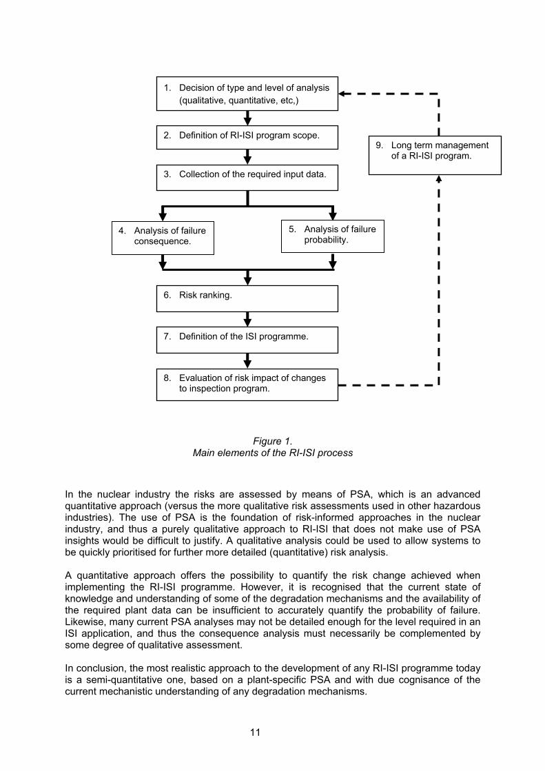
An overview of the fundamental aspects of most RI-ISI methodologies is depicted in Figure 1. This figure reflects the basic technical elements of the risk-informed concept as relevant to developing an ISI program. The following main steps summarize a typical RI-ISI process:
1. Decision of type and level of analysis (qualitative, quantitative, etc,)
2. Definition of RI-ISI program scope.
3. Collection of the required input data.
4. Analysis of failure consequence.
5. Analysis of failure probability.
6. Risk ranking.
7. Definition of the ISI programme.
8. Evaluation of risk impact of changes to inspection program.
9. Long term management of a RI-ISI program.
3.1 Type and level of analysis
Three different approaches to RI-ISI can be envisioned: quantitative, semi-quantitative and qualitative. In a quantitative approach, numerical estimates are determined for Probabilities of Failures (POFs) and Consequences of Failures (COFs). Fully validated and verified Structural Reliability Models (SRM) are used to determine POFs and the plant Probabilistic Safety Assessment is used to calculate COFs. In a qualitative approach, both the POFs and COFs are characterised by qualitative terms, such as very low, low, high, etc. In this framework, expert elicitation is used to rank the POF and COF of individual components. A semi-quantitative approach is one where the COFs are based on PSA results, but the PSA information may be expressed equally well in quantitative or qualitative terms. The failure probabilities may be partly evaluated using fully validated and verified SRM, but partly also using experience data and expert elicitation.
11
Figure 1. Main elements of the RI-ISI process
In the nuclear industry the risks are assessed by means of PSA, which is an advanced quantitative approach (versus the more qualitative risk assessments used in other hazardous industries). The use of PSA is the foundation of risk-informed approaches in the nuclear industry, and thus a purely qualitative approach to RI-ISI that does not make use of PSA insights would be difficult to justify. A qualitative analysis could be used to allow systems to be quickly prioritised for further more detailed (quantitative) risk analysis. A quantitative approach offers the possibility to quantify the risk change achieved when implementing the RI-ISI programme. However, it is recognised that the current state of knowledge and understanding of some of the degradation mechanisms and the availability of the required plant data can be insufficient to accurately quantify the probability of failure. Likewise, many current PSA analyses may not be detailed enough for the level required in an ISI application, and thus the consequence analysis must necessarily be complemented by some degree of qualitative assessment. In conclusion, the most realistic approach to the development of any RI-ISI programme today is a semi-quantitative one, based on a plant-specific PSA and with due cognisance of the current mechanistic understanding of any degradation mechanisms.
6. Risk ranking.
1. Decision of type and level of analysis (qualitative, quantitative, etc,)
2. Definition of RI-ISI program scope.
3. Collection of the required input data.
4. Analysis of failure consequence.
5. Analysis of failure probability.
7. Definition of the ISI programme.
8. Evaluation of risk impact of changes to inspection program.
9. Long term management of a RI-ISI program.

12
The risk assessment in a RI-ISI programme can be carried out either at the element level (e.g. each weld and discontinuity) or for groups of contiguous elements where all relevant conditions are the same.
The advantage of evaluation at element level is that the output will be unique for every element and there will be a clear distinction between elements. However, to reach this distinction between the elements, a rather large amount of detailed input data is needed which might be prohibitive from a cost point of view. Grouping elements with the same conditions (a process termed segmentation) is less time and resource consuming. The initial segmentation is normally based on the postulated direct consequences of a failure, but it is important that indirect consequences are also considered. Piping segments are normally defined at major components such as pumps, heat exchangers, check-valves, remote controlled valves or at pipe size changes.
3.2 Definition of RI-ISI program scope
The scope definition is a step in which the boundary of the programme is clearly identified, that is, which systems and which structural elements (circumferential welds, longitudinal welds, socket welds, attachments, lugs, etc.) are to be included in the programme. The scope of a RI-ISI programme can be either a full scope programme or (for instance when an alternative programme is already in place) a partial scope programme. A full scope programme can be defined as including all passive components and structures, including those relied upon to perform a nuclear safety function during all design-basis plant conditions and those whose failure could compromise the function of safety-related structures, systems, or components or could cause a reactor trip or actuation of a safety-related system. A partial scope programme can be defined as any subset of the systems or functions defining the full scope. A partial scope application is normally justified, for instance, if an alternative (deterministic) programme is in place for the other passive components or piping not addressed by the RI-ISI programme. A full scope RI-ISI programme is superior because it allows the treatment of all systems in a consistent and objective manner. Nonetheless, it is recognised that in the application of RI-ISI, a partial scope programme can be justified.
3.3 Collection of the required input data
Data collection is an essential part of the RI-ISI process, as it constitutes the basis for the whole analysis and decision process. The process of risk-informed inspection planning brings together a large amount of information from many different sources, which needs to be collected and analysed. This information can be classified in the following five categories:
1) Equipment data.
2) Historical plant operating data.
3) General nuclear industry information.
4) Safety Analysis Report and technical specifications.
5) PSA data.

13
The availability and accessibility of this information vary depending on the particular circumstances. Data collection is likely to be a resource-demanding phase in the RI-ISI process but the data gathered should be of considerable value for many safety or reliability related activities, such as periodic safety reviews.
3.4 Analysis of failure consequence
The failure of a passive component in a Nuclear Power Plant (NPP) can basically lead to one of the following classes of events of interest:
1) Initiating event: A pressure boundary failure occurs in an operating system resulting in an initiating event.
2) Loss of mitigating ability (stand-by): A pressure boundary failure occurs in a standby system and does not result in an initiating event, but degrades the mitigating capabilities of a system or train.
3) Loss of mitigating ability (demand): A pressure boundary failure occurs in a standby system when the system/train operation is required by an independent demand.
4) Combination: A pressure boundary failure causes an initiating event with an additional loss of mitigating ability.
The consequence analysis step of the RI-ISI process aims at evaluating the impacts of any of the above-mentioned events on plant risk. The consequence evaluation consists of the following primary steps:
a) A qualitative Failure Modes and Effects Analysis (FMEA) that determines the plant impacts of postulated failures of postulated sizes (e.g. small, medium, complete rupture). This step can consume the largest share of resources.
b) Qualification of the PSA for RI-ISI application.
c) Quantitative analysis with PSA.
PSA techniques have been developed since the 1970s [4] and PSA studies exist today for most types of nuclear power plants and individual power stations. Although the level of details and quality of these studies vary, the PSA methodology has become a well-known and frequently used tool in the analysis of nuclear safety. The following items are considered critical if a robust interface between PSA and RI-ISI is to be developed:
• The levels and scope of PSA to be used in RI-ISI (sub-section 3.4.1). • PSA quality, limitations and uncertainties (sub-section 3.4.2). • Passive component failure treatment (sub-section 3.4.3).
3.4.1 Levels and scope of PSA to be used in RI-ISI PSAs are performed at different levels, dealing with different types of consequences:
Level 1: Assessment of plant failures leading to Core Damage (CD) and the estimation of Core Damage Frequency (CDF).

14
Level 2: Estimation of off-site fission product release. Consequences are usually expressed in terms of Large Early Release Frequency (LERF).
Level 3: Assessment of off-site consequences leading to estimates of the effects of fission product release on human health. Consequences are usually expressed in terms of human fatalities, public radiation doses and environmental pollution.
All modern NPPs have plant-specific PSA studies, usually at Levels 1 and 2. Recent RI-ISI applications have mainly relied on the Level 1 consequence analysis. The use of Level 2 consequence (e.g. large early release) could be important for RI-ISI application, especially for reactors whose complete primary pressure boundary is not fully covered by the containment structure (for instance, RBMK and BWR reactors). In this case it must be borne in mind that Level 2 studies are based on assumptions and hypotheses that can be very difficult to verify in practice and thus are in general subject to higher uncertainties than Level 1 studies (i.e. estimates of core damage). 3.4.2 PSA quality, limitations and uncertainties Due to the small probabilities of failure of passive components in comparison with active components, the former usually only contribute to a small proportion of the total plant risk evaluated in the PSA study. Moreover, because of low probabilities of failure, the data available regarding passive failures is usually limited. This has naturally led to very limited treatment of such failures within PSA studies. Due consideration must be given to this fact and how the passive components should be treated in the consequence analysis. It is important that the PSA analysis employed reflect in a realistic way the actual design, construction, operational practices and operational experiences of the plant. It is a good practice to qualify and/or certify the PSA study for use in RI-ISI application, by fulfilling demands specified by ASME standard or IAEA standards/requirements. The qualification/certification could also be performed by peer review of the PSA for RI-ISI application. The qualification of the PSA should be documented [5-10]. Each PSA analysis is subject to unavoidable uncertainties, such as parameter uncertainties, model uncertainties and completeness uncertainties. Parameter uncertainties related to statistical data are usually quantified and a PSA study provides uncertainty boundaries as a part of its output. Model and completeness uncertainties are normally not included in the PSA study, but they have to be evaluated in the process of PSA qualification. 3.4.3 Passive component failure treatment Pipe breaks are modelled directly as initiating events such as Loss of Coolant Accidents (LOCAs), main steam or feed-water line breaks or flooding. PSA studies may spatially subdivide the pipework into zones and then consider various types of LOCAs occurring within the zone as initiating events but the studies do not normally model initiating events at segment or element level. Furthermore, the components are normally modelled in the PSA with two states: full function or total failure. In the case of piping, these states are ‘no leakage’ and ‘complete pipe break’. Thus, a ‘partly failed’ component (such as a crack or a small leak) that is handled by a manual action is not modelled in the basic PSA. As the modelling of structural components in the base PSA may be coarse and deficient for many systems, additional analysis is required to determine the consequences at the degree

15
of detail needed in RI-ISI. For instance, a complementary FMEA could be conducted in order to define both the direct and indirect impact of failure on plant operation. Indirect effects include failure consequences affecting other systems, components or piping segments, such as pipe whip, jet impingement, flooding, decompression waves, high environmental temperatures, etc. Indirect effects of passive component boundary failures may have a significant influence on the evaluation of core damage frequency. Spatial consequences are determined based on the location of the failure and relative position of important equipment. The base PSA does not usually include models of passive component failures that could result in the loss of mitigating ability (e.g. safety system pipe break). A way to address such situations is to identify basic events or groups of events already modelled in the PSA, whose failure captures the effects of a piping segment failure. This method is sometimes called the ‘surrogate component approach’.
3.5 Analysis of failure probability
The first step in the assessment of the probability of failure of a structural element is the identification of the potential degradation mechanisms. This requires the qualitative evaluation of a range of influential parameters, such as, design and fabrication information, loadings, environmental conditions, and inspection results. This analysis should be supported with a review of operating experience from the plant, its sister units and similar plants as well as insights from world-wide generic data. Ideally, the probability of failure of components or sites that are potentially in need of inspection should be calculated in a quantitative way, implying the use of Structural Reliability Models (SRMs). However, two important facts are recognised concerning the use of SRMs. Firstly, such models do not exist for all the potential degradation mechanisms that currently affect nuclear power plants. Secondly, for degradation mechanisms that do have a viable SRM, there is only a limited acceptance that these estimates can be seen as representing some form of true or absolute value. This implies that the evaluation of the probability of failure for all potential ISI sites will necessarily yield a mixture of quantitative and qualitative assessments. Quantitative values, where they exist, may serve to quantify relative differences in the probability of failure from one site to another. For these reasons, the most likely way failure probabilities can be presently estimated for RI-ISI applications is based on a combination of quantitative and qualitative assessments. Such an approach is referred to as a ‘semi-quantitative’ analysis. A semi-quantitative analysis of the probability of failure can be obtained by:
1) Use of structural reliability models, where they exist, to provide a good estimate of the relative differences in the failure probabilities (see 3.5.1).
2) Statistical estimates based on both plant-specific and global databases in order to provide anchoring points for both the SRM analysis and the expert judgments (see 3.5.2).
3) Use of formal expert judgements using a combination of deterministic structural models and design insights (see 3.5.3).
There is not a single, optimal method for estimating probabilities of failure.
16
3.5.1 Structural reliability models Structural reliability models (SRM) are essential tools in the evaluation of probabilities of failure for components of nuclear power plants, even if it must be recognised that there exist several degradation mechanisms which are not adequately covered with the available analytical tools. A clear advantage offered by SRMs is the possibility to quantify the influence of inspections both in terms of inspection capability and frequency. This is a key factor in RI-ISI since it is desirable to select the most appropriate inspection capability for every risk site. SRMs should be adequately verified and validated. To this end, a number of steps can be defined [11-14]:
1) The basic programming should be shown to have suitable quality assurance documentation.
2) The scope, the analytical assumptions and the limitations of the modelling capability should be well defined.
3) The analytical assumptions should be well grounded and based on theory that is accepted as representative of the situations considered by the given SRM.
4) The model should be capable of reproducing the data on which its analytical assumptions are based. Examples should be provided that can demonstrate its general agreement with the available experimental data.
5) Attempts should be made to show how the model compares with the world or field data, accepting the inherent limitation of this data.
6) The model should be benchmarked against other SRM models within the same field or scope and any differences should be adequately explained.
3.5.2 Estimation from operating experience data Operating experience data provides useful qualitative and quantitative information on the degradation of structural components. For example, Stress Corrosion Cracking (SCC) was discovered from field failures. Operating experience data covers not only leak and rupture data, but also other information on the presence of non-critical levels of degradation, such as small defects and wall thinning. The degradation information can be of considerable value in the development of SRMs and more generally in the assessment of structural failure probabilities. However, when reliability parameters are estimated from structural component failures or degradation databases, the following shortcomings have been identified:
1) Passive components usually have an increasing failure rate (i.e. ageing), and thus the exponential distribution does not correctly model the failure occurrence.
2) The data quality may be insufficient for obtaining reliable estimates due to missing information related to the component population or to uncertainties related to failure mechanisms and root causes.
3) Data is often very scarce. Due to the shortcomings related to the quality and quantity of data, the estimates of passive component failure probabilities are subject to large uncertainties. For RI-ISI applications, probability of failure estimates obtainable from world-wide or generic data may not be sufficient. However, the data can be extremely valuable in establishing prior probabilities.

17
These values can then act as an anchor for either the SRM estimates or expert judgement, using plant-specific information, to identify the distribution of the probability of failure throughout the plant-specific sites. 3.5.3 Use of expert judgement through expert elicitation A possible alternative to employing SRM or operating experience data is to use expert judgement, preferably through the use of formal expert elicitation. Well-structured expert elicitations can be a powerful tool for expanding the range of application of a RI-ISI. Such elicitations support and integrate individual expert judgements to provide an auditable set of probability of failure estimates. However, it is important to ensure that the use of this expert judgement is conducted within a structured expert elicitation process [15]. It is recognised that experts are often not very familiar with probabilities, especially with subjective probability statements, and must therefore be adequately trained. The person leading the structured expert elicitation, usually called "normative expert", must have proper knowledge in decision analysis, probabilities and statistics and has the responsibility to facilitate the process by giving training, conducting the elicitation and aggregating the expert opinions. A discussion on the expert assessment approach within the nuclear industry can be found for example in [15] and [16].
3.6 Risk ranking
Combining the estimates from the probability of failure and the consequence of failure assessments forms the risk ranking. The risk ranking can be carried out at either element level or segment level. (A segment is normally defined as a continuous length of piping with the same degradation mechanism and failure consequence.) 3.6.1 Graphical representation of risk Each segment or element can be ranked from highest to lowest according to its risk. A useful way to evaluate the risk of failure and clearly represent it in a graphical way is to develop a risk plot, a risk matrix or a Pareto risk diagram. In a risk plot, each component is represented as a point on a log-log plot. The consequence of failure is represented on the x-axis. The probability of failure is represented on the y-axis. Figure 2 gives an example of such a risk plot. A risk plot provides a clear picture of how the risk is distributed over the range of consequences. Given the nature of the risk plot, log-log axes, sites of constant risk are identified by straight lines. This fact greatly aids risk visualisation and ranking for the given parameters and assumptions. Parallel lines of constant risk can be drawn at fixed distances, identifying risk bands. In a semi-quantitative approach to risk, probability of failure and consequence of failure are not numerically evaluated in absolute terms, but are ranked using either a qualitative scale such as high, medium, low, or broad categories such as 10-3 to 10-4 etc. In this case, a risk matrix can be used to represent the rankings in the form of subsets as shown in Figure 3.

18
10-8 10-7 10-6 10-5 10-4 10-3 10-210-8
10-7
10-6
10-5
10-4
10-3
10-2
Consequence of Failure
Pro
babi
lity
of F
ailu
re
Figure 2 Risk plot (the plot is purely illustrative)
Conditional Consequence
Very Low Low Medium High Very
High
<10-6 10-6-10-5 10-5-10-4 10-4-10-3 >10-3
Very High >10-4
High 10-5-10-4
Medium 10-6-10-5
Low 10-7-10-6
Pro
babi
lity
of fa
ilure
Very Low <10-7
Figure 3
Risk Matrix (the values used in this table are purely illustrative and should in no way be taken as a requirement).
Risk decade
Lines of constant risk

19
3.6.2 Safety-significant sites The development of a ranking does not in itself identify directly the sites that will be selected for inspection, as discussed below. Further, in addressing this question, it must be borne in mind that in-service inspection leads to radiation exposure to the inspection personnel. Each combination of ISI programme is associated with a certain radiation exposure. In principle, it is possible to develop ISI programmes with the same risk reduction but with different total radiation exposure. Clearly, when faced with such choice, the RI-ISI programme resulting in as little radiation exposure as possible should be chosen. The process of identifying the safety-significant sites to be included in the inspection scope consists, broadly speaking, of two steps. The first step consists in the identification of risk outliers. Risk outliers are sites that have a much higher risk than the overall mean risk level for all sites. Risk outliers, dominating the overall risk, should be treated carefully to avoid giving a skewed view of the risk distribution. The very occurrence of risk outliers should be seen as a situation requiring special treatment. Inspection alone may not be considered sufficient to address the risk from such sites and consideration is normally given to other complementary methods (i.e. continuous monitoring, improved leak rate detection, load reduction, component replacement, etc.), The second step normally consists of identifying the potentially safety-significant sites. This is normally done by defining a risk value, relative to the highest risk (but excluding any outliers) that can be considered as the level separating potentially safety-significant sites from those that can be considered as non safety-significant. Sites falling above this level are considered as potentially safety-significant. The specific risk level chosen depends on many factors, and is a matter of agreement between the utility and the regulatory body. Among such factors are for example the risk distribution of the plant, the definition of risk outliers, the nature of risk associated with each site, and more in general, the ambition the utility has with its RI-ISI programme. An expert panel is then used to review the potentially safety-significant sites that have been identified. This panel is formed by several individuals with expertise in all the relevant technical areas related to the RI-ISI process, and has the task to review the information, analysis and insights that have been used to identify the safety significant sites [15]. More in detail, the expert panel review process can cover: • Verification that the technical basis for defining the scope of the programme is sound. • Verification that the system boundaries are clearly defined and that the delineation of
piping segments can be justified. • Verification that the failure consequences assessed for each segment are accurate
(both direct and indirect). • Verification that the procedures for estimating failure probability have been based on
appropriate databases, analytical methods and/or Structural Reliability Models (SRMs). • Verification that, if SRMs have been used, the limitations in the models and in the key
input parameters have been assessed. • Verification that the estimated failure rates have addressed the limiting failure type
(small leak, disabling leak or break), the relevant failure mechanisms and ageing effects, normal and design-limiting loadings, design and fabrication factors and material properties.
• Verification that the estimated failure rates are consistent with plant operating history.

20
• Verification of the consistency of classification among segments within a system and between systems.
• Verification that uncertainties have been properly considered and treated. • Review of the selected piping segments in order to identify any proposed relaxation in
inspection requirements from prior practices and assess their effect on plant safety. • Consideration of strategies other than inspection.
To summarise, the expert panel determine a ranking of safety significant sites, using qualitative and quantitative information from PSA and failure probability evaluations and in combination with traditional engineering insights and design basis information. This ranking identifies the primary candidates for inclusion in a risk-informed inspection programme. The next step is to make the final selection, i.e. to define the ISI programme.
3.7 Definition of the ISI programme
The overall principle underlying the definition of the RI-ISI programme, e.g. the identification and selection of individual sites for inspection, is that the proposed inspection programme must ensure the maintenance of an adequate level of defence in depth. After having identified a risk ranking of the safety-significant sites, the sub-set to be included in the inspection programme must be determined. In selecting these sites, other criteria than risk are normally considered. Such criteria are, for example, the severity of the degradation mechanisms, radiation doses that the inspectors will receive, ease of accessibility, inspection costs, etc. Sites whose calculated risk is not particularly high in the ranking, but that are characterised by a particularly high value of the failure consequence (and, necessarily, by a low probability of failure) are normally considered for inclusion. Inspecting these sites is typically justified on the ground of defence-in-depth. Due consideration is also given to the reverse situation, i.e. sites characterised by low consequence but high probability of failure sites. Inspecting these sites can contribute to increase plant availability and it can thus make economic sense to include them in the inspection programme. After having established an initial selection of candidate sites based on these criteria, the risk associated with such elements is compared with the risk associated with the sites forming the scope of the current (deterministic) ISI programme. Typically, when moving to a RI-ISI programme from a traditional one, the Regulator demands that a risk reduction is achieved. Risk neutrality, or even a small risk increase (when offset by other advantages, such as a marked reduction of radiation doses to workers) can be acceptable, when agreed between the utility and the Regulator. The risk reduction achieved depends not only on the risk addressed, but also on the capability and frequency (intervals) of the inspections. This is discussed below. The scope of the RI-ISI programme may also need to be completed adding sites which require inspection in order to meet other legal requirements, for instance in relation to the safety protection of workers, etc.

21
3.7.1 Inspection intervals Currently, most in-service inspection intervals are either set by a code, such as ASME section XI [17], by some consensus between the regulator and the utility or by some form of deterministic principle, usually based on design considerations and general technical experience. In principle, optimal inspection intervals could be determined by means of, for example, validated SRMs coupled with the knowledge of Probability of Detection (POD) curves [18]. 3.7.2 Inspection qualification Within Europe, ENIQ has an established methodology for inspection qualification [1]. An essential input to the ENIQ qualification process is the identification of appropriate inspection qualification requirements defining the defects of concern for which highly reliable detection and sizing is to be demonstrated. The ENIQ qualification process, if followed to a successful outcome, provides high confidence that the inspection system can achieve the inspection qualification requirements for defect sizing and detection. The ENIQ qualification process does not provide a quantitative measure of inspection efficiency. Typically, the output statement from the ENIQ qualification process is expressed in linguistic terms such as ‘highly reliable’ or ‘highly efficient’. A model has been proposed to use expert judgement to quantify a qualitative qualification process [19].
3.8 Evaluation of risk impact of changes to inspection program
A quantitative estimate of the risk reduction achieved can only be calculated if a quantitative measure of the inspection capability (for instance, a POD curve) is known. When such a measure of the inspection capability is available, a structural reliability model could be used to quantify the risk reduction. In many cases, this measure is either not available or it would require a disproportionate use of resources to obtain it. To gain confidence that the proposed RI-ISI programme is at least as effective as the current ISI programme in reducing risk, the ISI programmes can be compared by using as input the risk estimates of each site, the inspection intervals, and a hypothetical probability of detection. This assessment should confirm that the initial selection of elements for the RI-ISI programme does not produce an unacceptable risk impact. If an unacceptable risk impact is calculated, then adjustments to the selection of elements to meet the risk acceptance criteria may be carried out.
3.9 Long term management of a RI-ISI program
The risk assessment provides a snapshot of the risk distribution within the ISI boundary at a given point in time. The risk assessment can be kept ‘live’ so that it reflects as accurately as possible the distribution of risk within the ISI boundary. Changes in the calculated risk can arise either from a change in the failure probability or from a change in the consequences of the failure. The main issues with a potential influence on risk ranking are:

22
• Plant changes; • Changes in operating and maintenance procedures; • Changes in input information for failure probability and consequence evaluation, due to,
for example, operating experience; • Changes in models used for failure probability and consequence estimation.
The determination of an effective risk-informed inspection strategy typically requires the development of a feedback procedure based on the idea of updating the risk ranking after plant changes affecting the probabilities of failure or consequences of failure have taken place. The affected portions of the RI-ISI programme are re-evaluated as new information affecting the implementation of the programme becomes available (component system design change, plant PSA changes, plant operating condition changes, industry-wide failure notifications, etc). Also very relevant is the information collected after one inspection programme has been completed, as this increases the knowledge of the plant. This information clearly influences the assessment of the site probability of failure as the uncertainty concerning the presence or absence of a degradation mechanism is changed. This "living" process is one of the strengths of the risk-informed approach, as it leads to an enabling process that is both flexible and responsive to emerging problems. If evidence of significant damage is found by inspection it is assumed that actions are taken to reduce the increased risk. These actions include substitution, repair, or fitness for purpose assessments to justify maintenance in service coupled with prescriptive follow-up inspections of the affected locations at subsequent outages. Even if no evidence of defects is found after the risk-informed ISI programme is completed, it is still important to evaluate the meaning of the result. An important issue then becomes the capability of the inspection technique. ENIQ TGR has developed a discussion document on this issue [20]. Some guidance regarding living probabilistic safety assessment can be found in [21]. Reference [22] provides eight examples of plants that have conducted updates to their RI-ISI programmes.

23
4 References 1. European Methodology for Qualification of Non-Destructive Testing, Issue 3, ENIQ
report No 31, EUR 22906 EN, 2007. 2. European framework document for risk-informed in-service inspection, ENIQ report No
23, EUR 21581 EN, 2005. 3. Defence in Depth in Nuclear Safety, INSAG- 10, IAEA, Vienna, Austria, 1996. 4. WASH-1400 (NUREG-75/014), Reactor Safety Study, An Assessment of Accident
Risks in U.S. Commercial Nuclear Power Plants, U.S. Nuclear Regulatory Commission, October 1975.
5. ASME - Standard for Probabilistic Risk Assessment for Nuclear Power Plant Applications- RA-S-2002.
6. Probabilistic Risk Assessment Peer Review Process Guidance, Revision A3, Nuclear Energy Institute, NEI-00-02, March 2002.
7. A Framework for Quality Assurance Programme for PSA, IAEA TECDOC 1101, 1999. 8. Applications of Probabilistic Safety Assessment (PSA) for nuclear power plants, IAEA-
TECDOC-1200, 2001. 9. Review of Probabilistic Safety Assessments by Regulatory Bodies, Safety Reports
Series No. 25, 2002. 10. Determining the quality of probabilistic safety assessment (PSA) for applications in
nuclear power plants, IAEA-TECDOC-1511, July 2006. 11. O.J.V. Chapman, “Definition of a set of criteria that should be met by a suitable
structural reliability model”, NURBIM report D2, May 2004. 12. B. Brickstad, “WP-4, Review and benchmarking of SRMs and associated software”,
NURBIM report D4, May 2004. 13. H. Schulz, T. Schimpfke, B. Brickstad, O.J.V. Chapman, B. Shepherd, S. Kelly, S.
Olsson, J. Wintle, A. Muhammed, K. Simola, NURBIM Final Report, Fifth Framework of the European Atomic Energy Community (EURATOM), Project: NURBIM, Contract No. FIKS-CT-2001-00172, ftp://ftp.cordis.europa.eu/pub/fp5-euratom/docs/nurbim_projrep_en.pdf
14. ENIQ Recommended Practice 9: Verification and Validation of Structural Reliability Models and Associated Software to Be Used in Risk-Informed In-Service Inspection Programmes, ENIQ report No 30, EUR 22228 EN, 2007.
15. ENIQ Recommended Practice 11: Guidance on Expert Panels in RI-ISI, ENIQ report No 34, EUR 22234 EN, 2008
16. Severe Accident Risks: An Assessment for Five U.S. Nuclear Power Plants, Final Report, US NRC NUREG-1150, Vols. 1-3, December 1990.
17. ASME Boiler and Pressure Vessel Code, Section XI: Rules for In-service Inspection of Nuclear Power Plant Components, Document Number: ASME Section XI, American Society of Mechanical Engineers, 2001.
18. L. Gandossi & C. Annis, ENIQ TGR Technical Document: Probability of Detection Curves - Statistical Best-Practices, ENIQ report No 41, 24429 EN – 2010
19. L. Gandossi & K. Simola, A Bayesian Framework for the Quantitative Modelling of the ENIQ Methodology for Qualification of Non-Destructive Testing, EUR 22675 EN, 2007.
20. ENIQ TGR Discussion Document: Updating of Risk-Informed Inspection Programmes, ENIQ Report No 37, EUR 23929 EN, December 2009.
21. Living Probabilistic Safety Assessment (LPSA), IAEA-TECDOC-1106, 1999. 22. Living Program Guidance To Maintain Risk Informed In-service Inspection Programs
For Nuclear Plant Piping Systems, Nuclear Energy Institute, NEI 04-05, April 2004.

European Commission EUR 25199 EN – Joint Research Centre – Institute for Energy and Transport Title: ISK-INFORMED IN-SERVICE INSPECTION: AN OVERVIEW FOR THE NON-SPECIALIST Author: Luca GANDOSSI (DG-JRC-IET) Luxembourg: Publications Office of the European Union 2012 – 24 pp. – 21 x 29.7 cm EUR – Scientific and Technical Research series – ISSN 1831-9424 ISBN 978-92-79-23017-2 doi:10.2790/42657 Abstract The European Framework Document for Risk-Informed In-Service Inspection (RI-ISI) (ENIQ report 23) was published in 2005, with the goal to provide general guidelines to utilities both for developing RI-ISI approaches and for using pre-established approaches or adapting them to the European nuclear environment, taking into account national regulatory requirements and utility-specific characteristics. The purpose of this document is to provide an overview of the Framework Document and how the process of RI-ISI is commonly applied within Europe and elsewhere. It is intended as a reference source for a wide audience of engineers and technical staff who may not be routinely involved with RI-ISI, but who may benefit from a greater understanding and appreciation of the issues arising when applying risk concepts to the definition of an inspection program.

How to obtain EU publications Our priced publications are available from EU Bookshop (http://bookshop.europa.eu), where you can place an order with the sales agent of your choice. The Publications Office has a worldwide network of sales agents. You can obtain their contact details by sending a fax to (352) 29 29-42758.

The mission of the JRC is to provide customer-driven scientific and technical support for the conception, development, implementation and monitoring of EU policies. As a service of theEuropean Commission, the JRC functions as a reference centre of science and technology for the Union. Close to the policy-making process, it serves the common interest of theMember States, while being independent of special interests, whether private or national.
LD
-NA
-25199-EN-N