enhancing the ok1dfc square septum feed with a …enhancing the ok1dfc square septum feed with a...
TRANSCRIPT

Enhancing the OK1DFC Square Septum Feed With a Choke Ring or Chaparral-style Horn
and A Comparison of some Septum Polarizers
Paul Wade W1GHZ ©2007 [email protected]
A previous investigation1 of the properties of the VE4MA feedhorn2, a circular waveguide horn with a single choke ring, led to the discovery of some combinations of dimensions that can provide significantly enhanced performance. One set of dimensions, which we called the “Super-VE4MA,” showed higher calculated dish efficiency than any other prime-focus feedhorn. These calculated results have been substantiated by sun noise measurements made independently by WD5AGO and others. It seems likely that the OK1DFC septum feed3,4 could also be enhanced by adding a choke ring, as shown in Figure 1, and optimizing the choke dimensions. The results suggest that there is a set of choke dimensions which can provide calculated efficiency for circular polarization nearly as high as the Super-VE4MA feed. However, the tolerance on dimensions for good performance is more limited than with the circular waveguide, making it more difficult to utilize available materials. The results for the enhanced OK1DFC septum feed have not yet been substantiated by measurement.
Figure 1 Septum feed with choke ring (from WA5WCP)
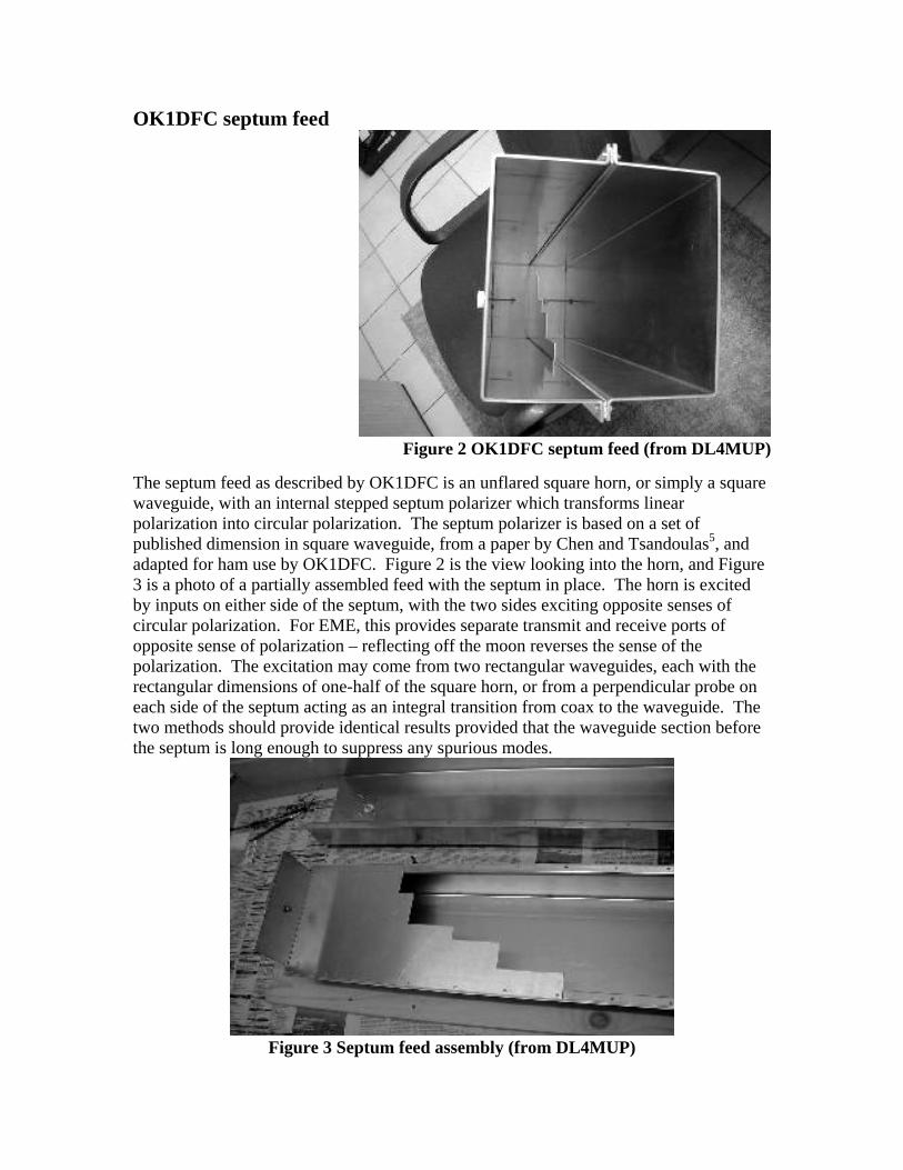
OK1DFC septum feed
Figure 2 OK1DFC septum feed (from DL4MUP)
The septum feed as described by OK1DFC is an unflared square horn, or simply a square waveguide, with an internal stepped septum polarizer which transforms linear polarization into circular polarization. The septum polarizer is based on a set of published dimension in square waveguide, from a paper by Chen and Tsandoulas5, and adapted for ham use by OK1DFC. Figure 2 is the view looking into the horn, and Figure 3 is a photo of a partially assembled feed with the septum in place. The horn is excited by inputs on either side of the septum, with the two sides exciting opposite senses of circular polarization. For EME, this provides separate transmit and receive ports of opposite sense of polarization – reflecting off the moon reverses the sense of the polarization. The excitation may come from two rectangular waveguides, each with the rectangular dimensions of one-half of the square horn, or from a perpendicular probe on each side of the septum acting as an integral transition from coax to the waveguide. The two methods should provide identical results provided that the waveguide section before the septum is long enough to suppress any spurious modes.
Figure 3 Septum feed assembly (from DL4MUP)
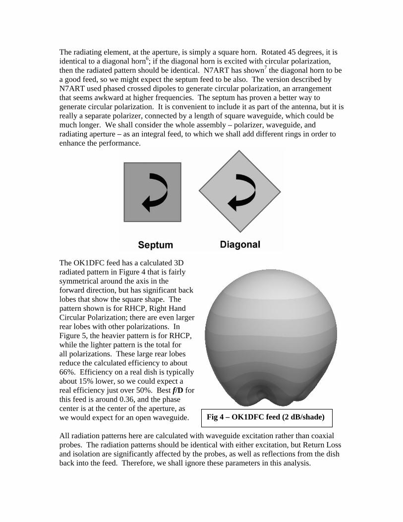
The radiating element, at the aperture, is simply a square horn. Rotated 45 degrees, it is identical to a diagonal horn6; if the diagonal horn is excited with circular polarization, then the radiated pattern should be identical. N7ART has shown7 the diagonal horn to be a good feed, so we might expect the septum feed to be also. The version described by N7ART used phased crossed dipoles to generate circular polarization, an arrangement that seems awkward at higher frequencies. The septum has proven a better way to generate circular polarization. It is convenient to include it as part of the antenna, but it is really a separate polarizer, connected by a length of square waveguide, which could be much longer. We shall consider the whole assembly – polarizer, waveguide, and radiating aperture – as an integral feed, to which we shall add different rings in order to enhance the performance.
The OK1DFC feed has a calculated 3D radiated pattern in Figure 4 that is fairly symmetrical around the axis in the forward direction, but has significant back lobes that show the square shape. The pattern shown is for RHCP, Right Hand Circular Polarization; there are even larger rear lobes with other polarizations. In Figure 5, the heavier pattern is for RHCP, while the lighter pattern is the total for all polarizations. These large rear lobes reduce the calculated efficiency to about 66%. Efficiency on a real dish is typically about 15% lower, so we could expect a real efficiency just over 50%. Best f/D for this feed is around 0.36, and the phase center is at the center of the aperture, as we would expect for an open waveguide. Fig 4 – OK1DFC feed (2 dB/shade) All radiation patterns here are calculated with waveguide excitation rather than coaxial probes. The radiation patterns should be identical with either excitation, but Return Loss and isolation are significantly affected by the probes, as well as reflections from the dish back into the feed. Therefore, we shall ignore these parameters in this analysis.

OK1DFC Square Septum Feed without choke ring
Figure 5
Dish diameter = 20 λ Feed diameter = 1.7 λ
E&H-planes
45° plane
0 dB -10 -20 -30
Fee
d R
adia
tio
n P
atte
rn
W1GHZ 2007
0 10 20 30 40 50 60 70 80 90-90
-67.5
-45
-22.5
0
22.5
45
67.5
90
Rotation Angle aroundF
eed
Ph
ase
An
gle
E-plane
H-plane
specifiedPhase Center = 0 λ beyond aperture
0.3 0.4 0.5 0.6 0.7 0.8 0.90.25 1.0
10
20
30
40
50
60
70
80
90
1 dB
2 dB
3 dB
4 dB
5 dB
6 dB
7 dB8 dB
MAX Possible Efficiency with XPOL loss & Phase error
REAL WORLD at least 15% lower
MAX Possible Efficiency without XPOL or Phase error
MAX Efficiency with phase error ONLYIllumination
Spillover
AFTER LOSSES:
Feed Blockage
Parabolic Dish f/D
Par
abo
lic D
ish
Eff
icie
ncy
%

Dish illumination review The ideal illumination for a parabolic dish antenna would provide uniform energy over the reflector surface, with no spillover energy missing the dish. Real feed antennas do not provide this ideal distribution. Figure 6, from the W1GHZ Microwave Antenna Book – Online8, shows the desired illumination vs. a typical (idealized) feed pattern. The typical pattern energy decreases from the central peak, while the desired pattern energy increases toward the edges to compensate for space attenuation – the edge of the dish is farther from the feed than the center of the dish. The typical feed pattern also has spillover energy which misses the reflector, and real feeds have sidelobes and backlobes which also waste energy. For simple feeds, it has been found that the tradeoff between illumination and spillover yielding best efficiency occurs when the illumination (not the feed pattern – we must account for space attenuation) is about 10 dB down at the edge of the dish. This 10 dB illumination taper is just a rule-of-thumb; for accurate analysis, we use pattern integration9,10, calculating the efficiency for the full three-dimensional feed pattern. For well behaved feeds, only a few cuts through the 3D pattern, typically the E- and H-plane cuts, are necessary, but for these square feeds, the 45-degree cuts can be significantly different and must be included. Note: all efficiency calculations here are for an arbitrary 20λ dish diameter and a 1.7λ feed diameter, or a constant blockage ratio of 0.085, so that we are comparing apples to apples. For small dishes, the actual blockage is more significant and efficiency should be recalculated. Also, the numbers cited here may differ slightly from those previously published11, as antenna modeling and efficiency calculations have both improved. Choke Ring The VE4MA feed2 adds a single ring, often referred to as a choke ring, around an open circular waveguide horn. This ring reduces side and back lobes, thus increasing efficiency by putting more of the energy on the reflector and reducing spillover. Certain combinations of ring dimensions also shape the radiation pattern distribution on the reflector to better approximate our desired dish illumination in Figure 6, with more of the energy toward the rim of the dish. Note that the common rule-of-thumb, a 10 dB illumination taper, is not valid for these enhanced feed patterns – we must calculate or measure radiation patterns, then integrate the patterns over the reflector surface to calculate efficiency. Radiation patterns for these horns are calculated using Ansoft12 HFSS electromagnetic-field simulation software. The septum feed was simulated with a range of ring dimensions and positions, calculating dish efficiency for each and looking for combinations which provide enhanced efficiency. For the VE4MA feed, the originally published ring size was ½ λ wide and ½ λ deep, while the ring size which provides best dish efficiency1, the “Super-VE4MA,” is about 0.6λ wide and 0.45λ deep. The ring width rather than diameter is specified since the diameter of the circular waveguide in the

f/D = 0.4
Illumination taper = 10 dB
Figure 6. Typical vs. Desired Dish Illumination
N1BWT 1994
0 dB -10 dB -20 dB
Spillover loss
Illumination loss
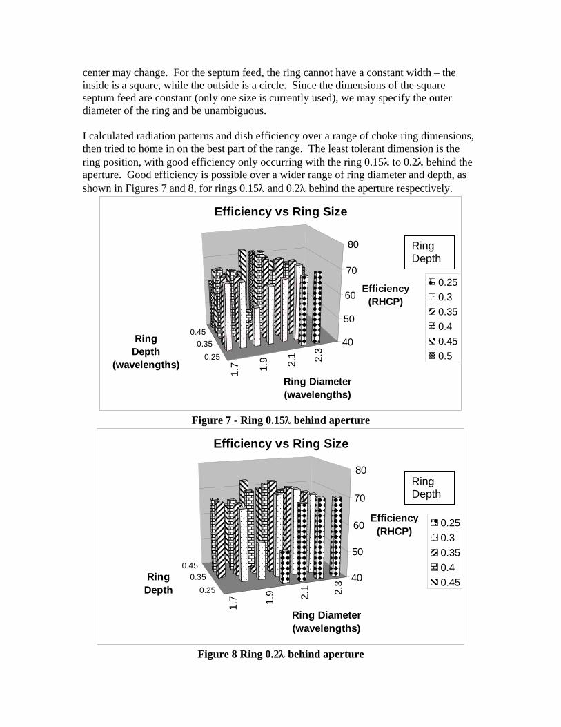
center may change. For the septum feed, the ring cannot have a constant width – the inside is a square, while the outside is a circle. Since the dimensions of the square septum feed are constant (only one size is currently used), we may specify the outer diameter of the ring and be unambiguous. I calculated radiation patterns and dish efficiency over a range of choke ring dimensions, then tried to home in on the best part of the range. The least tolerant dimension is the ring position, with good efficiency only occurring with the ring 0.15λ to 0.2λ behind the aperture. Good efficiency is possible over a wider range of ring diameter and depth, as shown in Figures 7 and 8, for rings 0.15λ and 0.2λ behind the aperture respectively.
1.7 1.9 2.1 2.3
0.250.35
0.4540
50
60
70
80
Efficiency (RHCP)
Ring Diameter(wavelengths)
Ring Depth
(wavelengths)
Efficiency vs Ring Size
0.250.30.350.40.450.5
Ring Depth
Figure 7 - Ring 0.15λ behind aperture
1.7 1.9 2.1 2.3
0.250.35
0.4540
50
60
70
80
Efficiency (RHCP)
Ring Diameter(wavelengths)
Ring Depth
Efficiency vs Ring Size
0.250.30.350.40.45
Ring Depth
Figure 8 Ring 0.2λ behind aperture

When we plot efficiency vs ring diameter, in Figures 9 and 10 for rings 0.15λ and 0.2λ behind the aperture respectively, it is quite apparent that the best ring diameter is about 2.0λ, and the best depth is in the 0.3λ to 0.4λ range. A slightly smaller diameter, 1.9λ, provides very poor efficiency with some ring depths, so it is best to err on the larger side.
Square Septum Feed - Ring variations
404550556065707580
1.5 1.7 1.9 2.1 2.3 2.5
Ring Diameter
Dis
h Ef
ficie
ncy 0.25
0.30.350.40.450.5
Ring Depth
Figure 9 – Efficiency vs Ring dimensions with ring 0.15λ behind aperture
Square Septum Feed - Ring variations
404550556065707580
1.7 1.8 1.9 2.0 2.1 2.2 2.3
Ring Diameter
Dis
h Ef
ficie
ncy 0.25
0.30.350.40.45
Ring Depth
Figure 10 – Efficiency vs Ring dimensions with ring 0.2λ behind aperture
OK1DFC Septum with Ring 2.0 lambda Diameter
62
64
66
68
70
72
74
76
0.05 0.15 0.25 0.35 0.45
Ring position behind rim
Dis
h Ef
ficie
ncy
0.32
0.34
0.36
0.38
0.4
0.42
0.44
0.46
f/D
Efficiency 0.3 deepEfficiency 0.35 deepEfficiency 0.4 deepf/D 0.3 deepf/D 0.35 deepf/D 0.4 deep
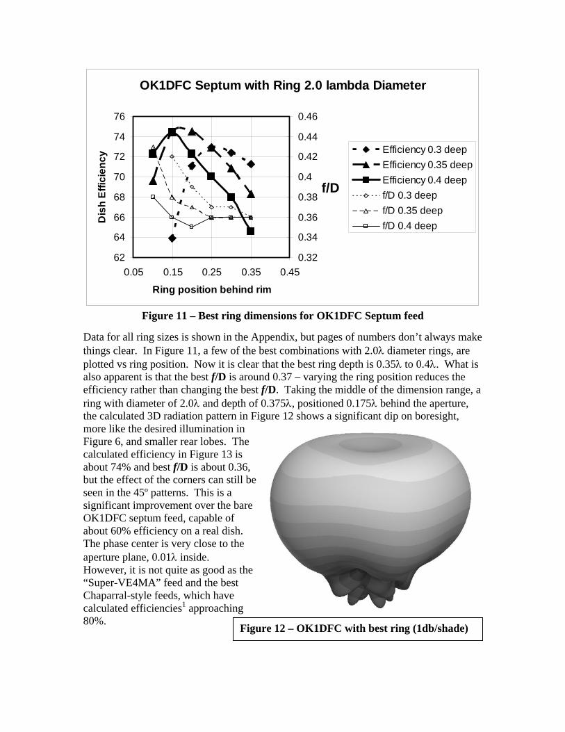
Figure 11 – Best ring dimensions for OK1DFC Septum feed
Data for all ring sizes is shown in the Appendix, but pages of numbers don’t always make things clear. In Figure 11, a few of the best combinations with 2.0λ diameter rings, are plotted vs ring position. Now it is clear that the best ring depth is 0.35λ to 0.4λ. What is also apparent is that the best f/D is around 0.37 – varying the ring position reduces the efficiency rather than changing the best f/D. Taking the middle of the dimension range, a ring with diameter of 2.0λ and depth of 0.375λ, positioned 0.175λ behind the aperture, the calculated 3D radiation pattern in Figure 12 shows a significant dip on boresight, more like the desired illumination in Figure 6, and smaller rear lobes. The calculated efficiency in Figure 13 is about 74% and best f/D is about 0.36, but the effect of the corners can still be seen in the 45º patterns. This is a significant improvement over the bare OK1DFC septum feed, capable of about 60% efficiency on a real dish. The phase center is very close to the aperture plane, 0.01λ inside. However, it is not quite as good as the “Super-VE4MA” feed and the best Chaparral-style feeds, which have calculated efficiencies1 approaching 80%.
Figure 12 – OK1DFC with best ring (1db/shade)
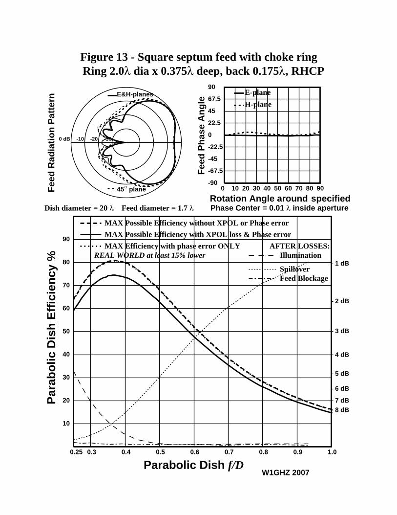
Figure 13 - Square septum feed with choke ring Ring 2.0λ dia x 0.375λ deep, back 0.175λ, RHCP
Dish diameter = 20 λ Feed diameter = 1.7 λ
E&H-planes
45° plane
0 dB -10 -20 -30
Fee
d R
adia
tio
n P
atte
rn
W1GHZ 2007
0 10 20 30 40 50 60 70 80 90-90
-67.5
-45
-22.5
0
22.5
45
67.5
90
Rotation Angle aroundF
eed
Ph
ase
An
gle
E-plane
H-plane
specifiedPhase Center = 0.01 λ inside aperture
0.3 0.4 0.5 0.6 0.7 0.8 0.90.25 1.0
10
20
30
40
50
60
70
80
90
1 dB
2 dB
3 dB
4 dB
5 dB
6 dB
7 dB8 dB
MAX Possible Efficiency with XPOL loss & Phase error
REAL WORLD at least 15% lower
MAX Possible Efficiency without XPOL or Phase error
MAX Efficiency with phase error ONLYIllumination
Spillover
AFTER LOSSES:
Feed Blockage
Parabolic Dish f/D
Par
abo
lic D
ish
Eff
icie
ncy
%

Other f/D The ring dimensions above provide best performance for an f/D around 0.36, the same as the bare OK1DFC septum feed. However, many dishes have different f/D, larger or smaller. The data in the Appendix shows some other combinations of dimensions that do not provide quite as high efficiency, but still provide significant enhancement for other f/D ranges. For shallower dishes, a larger ring with diameter of 2.1λ and depth of 0.3λ to 0.35λ can provide good performance for f/D ranging from 0.35 to 0.43 by varying the ring position, as shown in Figure 14.
OK1DFC Septum, Ring 2.1 dia x 0.35 deep
676869
70717273
7475
0 0.1 0.2 0.3
Ring position behind rim
Dis
h Ef
ficie
ncy
-0.3-0.2-0.1
00.10.20.3
0.40.5
f/DEfficiency
f/D
Phase Center
Figure 14 – Larger ring for f/D > 0.35
For deeper dishes, a smaller ring with diameter of 1.7 to 1.8λ and depth of 0.4λ can provide good performance for f/D as low as 0.3, shown in Figure 15.
OK1DFC Septum, Ring 1.8 dia x 0.4 deep
62
63
64
65
66
67
68
0.05 0.15 0.25 0.35
Ring position behind rim
Dis
h Ef
ficie
ncy
-0.2
-0.1
0
0.1
0.2
0.3
0.4
f/DEfficiency
f/D
Phase Center
Figure 15 – Smaller ring for f/D < 0.35
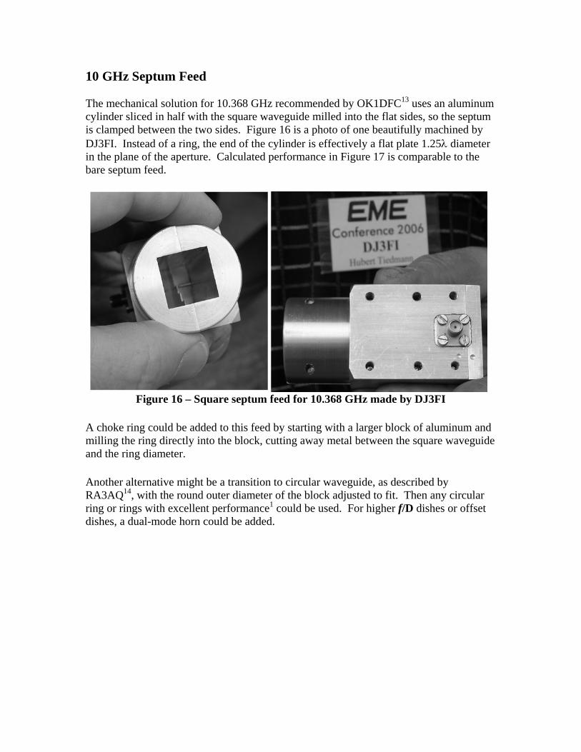
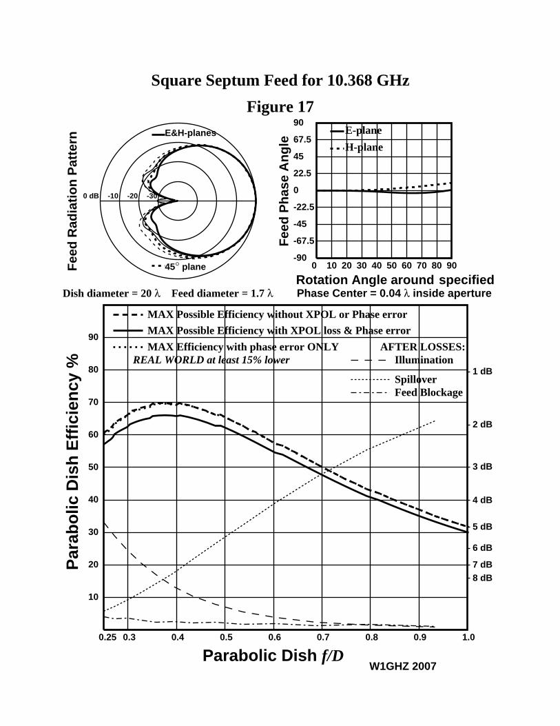
10 GHz Septum Feed The mechanical solution for 10.368 GHz recommended by OK1DFC13 uses an aluminum cylinder sliced in half with the square waveguide milled into the flat sides, so the septum is clamped between the two sides. Figure 16 is a photo of one beautifully machined by DJ3FI. Instead of a ring, the end of the cylinder is effectively a flat plate 1.25λ diameter in the plane of the aperture. Calculated performance in Figure 17 is comparable to the bare septum feed.
Figure 16 – Square septum feed for 10.368 GHz made by DJ3FI
A choke ring could be added to this feed by starting with a larger block of aluminum and milling the ring directly into the block, cutting away metal between the square waveguide and the ring diameter. Another alternative might be a transition to circular waveguide, as described by RA3AQ14, with the round outer diameter of the block adjusted to fit. Then any circular ring or rings with excellent performance1 could be used. For higher f/D dishes or offset dishes, a dual-mode horn could be added.
Square Septum Feed for 10.368 GHz
Figure 17
Dish diameter = 20 λ Feed diameter = 1.7 λ
E&H-planes
45° plane
0 dB -10 -20 -30
Fee
d R
adia
tio
n P
atte
rn
W1GHZ 2007
0 10 20 30 40 50 60 70 80 90-90
-67.5
-45
-22.5
0
22.5
45
67.5
90
Rotation Angle aroundF
eed
Ph
ase
An
gle
E-plane
H-plane
specifiedPhase Center = 0.04 λ inside aperture
0.3 0.4 0.5 0.6 0.7 0.8 0.90.25 1.0
10
20
30
40
50
60
70
80
90
1 dB
2 dB
3 dB
4 dB
5 dB
6 dB
7 dB8 dB
MAX Possible Efficiency with XPOL loss & Phase error
REAL WORLD at least 15% lower
MAX Possible Efficiency without XPOL or Phase error
MAX Efficiency with phase error ONLYIllumination
Spillover
AFTER LOSSES:
Feed Blockage
Parabolic Dish f/D
Par
abo
lic D
ish
Eff
icie
ncy
%

Chaparral-style Square Septum Feed For linear polarization, Chaparral-style feed with multiple choke rings provide very good performance over a wide range of f/D. There are many combinations to choose from – so many that I chose not to start an investigation. Instead, I examined one described by OM6AA15, a square septum with three rings, each 0.225λ wide and 0.31λ deep, for a total blockage diameter of 1.98λ. These dimensions are close to dimensions which work well for linear polarization. The septum used the OK1DFC dimensions.
OM6AA photo
Performance of this feed is quite good over a wide range of f/D, from about 0.32 to 0.52, with the appropriate ring position, as shown in Figure 19. At the best position, the feed radiation pattern in Figure 18 has a dip in the middle like our ideal feed, and the calculated dish efficiency is plotted in Figure 20. Some XPOL loss is apparent – the polarization efficiency is about 95%. As the ring is moved back, exposing the square waveguide aperture, the pattern also becomes more square and CP efficiency decreases.
Fig 18 - 2 dB / shade
OK1DFC Square Septum with OM6AA 3-Ring Chaparral1.98 dia, 3 rings 0.225 wide x 0.31 deep
66676869707172737475
0 0.1 0.2 0.3
Ring position behind rim
Dish
Effi
cien
cy
-0.3-0.2-0.100.10.20.30.40.50.6
f/DEfficiencyf/DPhase Center
Figure 19 – Square Septum Chaparral – efficiency vs. ring position

Figure 20 - OM6AA Chaparral on OK1DFC Square SeptumThree Rings 0.225λ wide x 0.31λ deep, back 0.25λ, RHCP
Dish diameter = 20 λ Feed diameter = 1.7 λ
E&H-plane
45° plane
0 dB -10 -20 -30
Fee
d R
adia
tio
n P
atte
rn
W1GHZ 2007
0 10 20 30 40 50 60 70 80 90-90
-67.5
-45
-22.5
0
22.5
45
67.5
90
Rotation Angle aroundF
eed
Ph
ase
An
gle
E-plane
H-plane
specifiedPhase Center = 0.17 λ inside aperture
0.3 0.4 0.5 0.6 0.7 0.8 0.90.25
10
20
30
40
50
60
70
80
90
1 dB
2 dB
3 dB
4 dB
5 dB
6 dB
7 dB8 dB
MAX Possible Efficiency with XPOL loss & Phase error
REAL WORLD at least 15% lower
MAX Possible Efficiency without XPOL or Phase error
MAX Efficiency with phase error ONLYIllumination
Spillover
AFTER LOSSES:
Feed Blockage
Parabolic Dish f/D
Par
abo
lic D
ish
Eff
icie
ncy
%

Small dishes The best choke ring has a diameter of two wavelengths, so the blockage is much greater than a bare septum feed. Is the enhancement provided by the ring enough to overcome the additional blockage loss? In Figure 21, we can see that the calculated efficiency with the ring is reduced to about 68%, not too much better than 66% for the bare feed. So, for very small dishes, the addition of a choke ring hardly seems worthwhile. However, most of the photos of actual installations have mounting hardware, preamps, and relays that increase the blockage shadow. With careful planning, much of this hardware could be hidden behind the ring, so that the actual enhancement provided by the ring would be larger.
Circular Polarization and Cross-polarization losses Since circular polarization appears to present some additional difficulties with antenna performance and evaluation, perhaps a slightly deeper discussion would help our understanding. A good way to evaluate the performance of a dish antenna is by sun noise measurement, comparing the noise power received from the sun with the noise power received from cold sky. However, this does not evaluate the quality of circular polarization – noise is randomly polarized in both instances, so we may expect the same results as we measure for linear polarization. There are no celestial sources with well-defined polarization, so far-field polarization measurements for good-sized antennas are difficult unless a large anechoic chamber is available. A ground-reflection range of the type typically used for amateur antenna measurements is unsuitable for circular polarization; according to Hanson16, “on a ground reflection antenna test range, the antenna under test must be rotated, or tedious calibration procedures must be employed to account for the difference in the reflection coefficients of the range surface for the horizontal and vertical components of the field.” So we are at least partly dependent on simulations for evaluation of circularly-polarized antennas. We saw above that the dish efficiency of circularly-polarized feeds is not as good for deep dishes, with smaller f/D. Apparently, the circular polarization is not as good at the wider illumination angles (theta) needed for deep dishes. Frequently, the circularity of a CP antenna is given, or adjusted, by measurement of axial ratio for the feed boresight, but this is not as important for a prime-focus feed – the feed boresight is usually blocked. A CP feed must provide good circular polarization over the whole reflector, not just on boresight. Axial ratio Usually, circularity is measured and quantified by the axial ratio, the ratio of the strongest and weakest directions of polarization. Axial ratio on boresight is measured by rotating the antenna with linear polarization at the other end of a range, to find the strongest and weakest polarization components. For perfect circular polarization, the components are equal, the axial ratio is 0dB – it doesn’t matter how the linear antenna is oriented. The larger the axial ratio, the less circular and more elliptical is the polarization. For perfect linear polarization, the axial ratio is infinite. On most antenna ranges, ground reflections vary with different polarizations, as noted by Hanson above. Measurement of the axial ratio with several linear orientations and averaging may reduce the error.
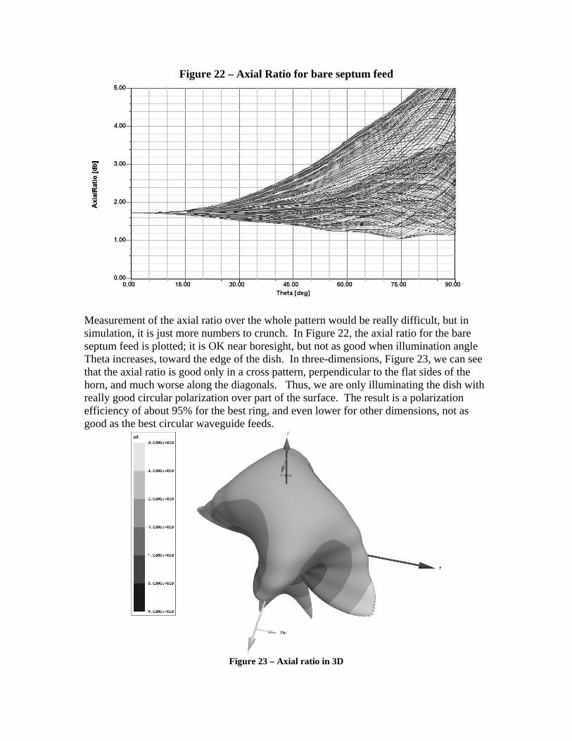
Figure 22 – Axial Ratio for bare septum feed
Measurement of the axial ratio over the whole pattern would be really difficult, but in simulation, it is just more numbers to crunch. In Figure 22, the axial ratio for the bare septum feed is plotted; it is OK near boresight, but not as good when illumination angle Theta increases, toward the edge of the dish. In three-dimensions, Figure 23, we can see that the axial ratio is good only in a cross pattern, perpendicular to the flat sides of the horn, and much worse along the diagonals. Thus, we are only illuminating the dish with really good circular polarization over part of the surface. The result is a polarization efficiency of about 95% for the best ring, and even lower for other dimensions, not as good as the best circular waveguide feeds.
Figure 23 – Axial ratio in 3D

When a ring is added to the septum feed, the axial ratio changes. Figure 24 is the axial ratio with the best ring from Figure 13, with a diameter of 2.0λ and depth of 0.375λ, positioned 0.175λ behind the aperture while Figure 25 is the smaller ring from Figure 15 providing better performance for very deep dishes. This smaller ring is 1.8λ in diameter and 0.4λ deep, positioned 0.2λ behind the aperture. The axial ratio shows even more variation with a ring than with the plain square septum.
Figure 24
Figure 25
Polarization Phase Shift Angle Most antennas radiate linear polarization; most communication antennas use either horizontal or vertical linear polarization. Only a few types, like the helical antenna, have inherent circular polarization. Polarization is defined as the plane in which the electric field, the E-field, has maximum amplitude. For example, a vertically-polarized antenna, like a vertical dipole, has an electric field which at one instant might be positive at the top and negative at the bottom; half a cycle later, it would reverse direction, to be positive at the bottom. In between, a quarter-cycle from the peaks, it would instantaneously pass through zero. In other polarization planes, the amplitude of the field would be smaller. To generate circular polarization with linearly-polarized antennas, we must add a second radiator perpendicular to the first, and excite it an electrical quarter-cycle (90°) later than the first, so that the electric field of the second radiator reaches a peak as the first passes through zero, and vice-versa. Thus, the positive end of the electric field travels in a circle rather than just reversing along a line. Since the field is also radiating from the antenna at the speed of light as it travels in a circle, we might visualize the positive end as travelling along a corkscrew. Circular polarization is characterized by the direction of travel – right-hand (RHCP) or left-hand (LHCP), like the threads on a machine screw. One way to excite the second radiator a quarter-cycle later is to add an electrical λ/4 delay; choosing which linear polarization is delayed controls the direction of circular rotation. Another common method for producing the delay is the use of a quadrature hybrid – a directional coupler with two outputs of equal amplitude but 90° phase difference. In waveguide, a thin dielectric sheet or card will delay energy polarized parallel to the plane of the sheet, but not perpendicularly polarized energy; the length of the sheet may be chosen to provide a quarter-wavelength of delay. A circular waveguide linearly excited at a 45° angle to a card with ¼λ delay will generate circular polarization. The 45° excitation is mathematically equivalent to two orthogonal components, but only the component parallel to the dielectric is delayed. The dielectric may be a material, like Teflon, or an artificial dielectric, for instance, a septum or a row of screws17 in the waveguide, adjusted to provide the desired delay for circular polarization. However the circular polarization is generated, the essential concept is that the polarization vector, the direction of the electric field, rotates 360º for each cycle of RF frequency. In free space, traveling at the speed of light, it also propagates one wavelength, or 360 electrical degrees, in this amount of time. Thus, each degree of physical rotation is also one degree of phase shift; if we consider two orthogonal components of the radiation, the polarization phase shift angle18 should also be 90º. What happens if we measure the extra quarter-wavelength of transmission line incorrectly, or change the frequency? Then we have two radiation components that do not have a 90º phase difference, and the resulting electric field will have reduced amplitude, by the sine of the angle, and a phase error. The resulting polarization will no longer be circular, but somewhat elliptical – some polarization directions are better than others. We characterize this error as circularity, or axial ratio, or polarization ratio. A

difference in amplitude for the two components can also cause the same error in circularity. A septum or dielectric polarizer of incorrect electrical length can also produce a phase difference other than 90º, resulting in imperfect circular polarization. The polarization vector may be resolved into two components with a phase difference, but measuring this difference in a radiated field is difficult (perhaps impossible). However, in software, this is easy – the components are just numbers. Since I was using Ansoft HFSS software12 to calculate the antenna patterns, it was easy to also look at the individual components, once I realized that this could provide insight into septum performance. Let’s examine the plain OK1DFC square septum feed. In Figure 26, we plot the polarization phase shift angle, the angle between the two components, vs Theta, the illumination angle of the feed (Theta = 0º on boresight). The polarization phase shift is about 78º over the whole forward hemisphere of the pattern, suggesting that the septum provides 78º rather than 90º of polarization phase shift. Is this a disaster? No, the sine of 78º is 0.978, or about -0.2 dB. Only a small loss, and we know that this feed provides good results for many EME stations.
OK1DFC Septum Feed
0
30
60
90
120
0 15 30 45 60 75 9
Theta
Pola
rizat
ion
Phas
e Sh
ift A
ngle
0
Figure 26

We can also examine the same septum polarizer in circular waveguide. In Figure 27, for a plain feed with no rings, the polarization phase shift is about 85º on boresight, becoming slightly worse as the illumination angle Theta increases. More interesting is that the polarization phase shift is not very frequency dependent – curves for frequencies from 2.1 to 2.5 GHz are almost identical. The polarization phase shift error is a function of the polarizer design, not the operating frequency. By coincidence, the septum designed for square waveguide actually works better in circular guide.
Figure 27
Does adding a ring to the feed affect the polarization phase shift angle? In Figure 28, we can see the variation. The best ring, from Figure 13, improves the polarization phase shift angle to near 90º over much of the illumination angle, while the smaller ring for deep dishes, from Figure 13, varies the angle around the original starting point.
OK1DFC Septum Feed - Effect of Ring
0
30
60
90
120
0 15 30 45 60 75 90
Theta
Pola
rizat
ion
Phas
e Sh
ift A
ngle
No RingBest RingDeep Dish
Figure 28

Another way of separating the effect of the ring is to excite a plain horn with perfect circular polarization – easy in software. In Figure 29, we can see that a plain circular waveguide horn and a diagonal horn (equivalent to a septum feed) feed with perfect circular polarization have a perfect polarization phase shift angle out to an illumination angle Theta of about 45º, beyond which they diverge. This may give us a clue why it the calculated efficiency of deep dishes is not as good with circular polarization – the feeds do not provide good CP over the full surface. We can also see that the ring of the Super-VE4MA feed distorts the polarization phase shift angle even with perfect circular polarization.
Feeds with perfect Circular Polarization
0
30
60
90
120
0 15 30 45 60 75 90
Theta
Pola
rizat
ion
Phas
e Sh
ift A
ngle
DiagonalRoundSuper VE4MA
Figure 29
We can also adjust the polarization phase shift in software to angles other than 90º, to find the relation between polarization phase shift angle and axial ratio. This is plotted in Figure 30 from simulations – there is probably a formula, but I didn’t look it up. Polarization ratio is also plotted; this is the ratio of desired CP to the opposite sense. Polarization ratio is even harder to measure accurately than axial ratio, since a pure source of circular polarization is required.
Axial and Polarization Ratiosvs Polarization Phase Shift Error
0
0.5
1
1.5
2
75 80 85 90 95 100 105
Polarization Phase Shift Angle
Axi
al R
atio
(dB
)
0
10
20
30
40
50
60
Pola
rizat
ion
Rat
io (d
B)
AxialPolarization
Figure 30

Other Septum Polarizers The OK1DFC septum dimensions are based on a paper by Chen and Tsandoulas5. A few other septum dimensions have been published, and we may compare them by looking at the polarization phase shift angle. The only other version with dimensions in the professional literature is by Bornemann19. Examples are given with different septum thicknesses. In Figure 31, we can see that the polarization phase shift angle increases with increasing septum thickness; at 2304 MHz, the optimum thickness is about ¼ inch, but it doesn’t appear to be critical. At higher frequencies, a thick septum might make fabrication easier, allowing the feed to be machined from a solid block of aluminum.
Bornemann Square Septum Feed Thick Septum (2304 MHz)
0
30
60
90
120
0 15 30 45 60 75 90
Theta
Pola
rizat
ion
Phas
e Sh
ift A
ngle
14.3mm thick9.2mm thick6.35mm thick1.04mm thick
Figure 31
The OK1DFC dimensions are for a thin septum; will increasing the thickness make the polarization phase shift angle closer to 90º? In Figure 32, the improvement is small, and never reaches 90º. More important is that the septum thickness is not critical, at least for circular polarization; the effect on isolation is larger.
OK1DFC Square Septum Feed Thick Septum (2304 MHz)
0
30
60
90
120
0 15 30 45 60 75 90
Theta
Pola
rizat
ion
Phas
e Sh
ift A
ngle
20mm thick15mm thick10mm thick1.04mm thick
Figure 32
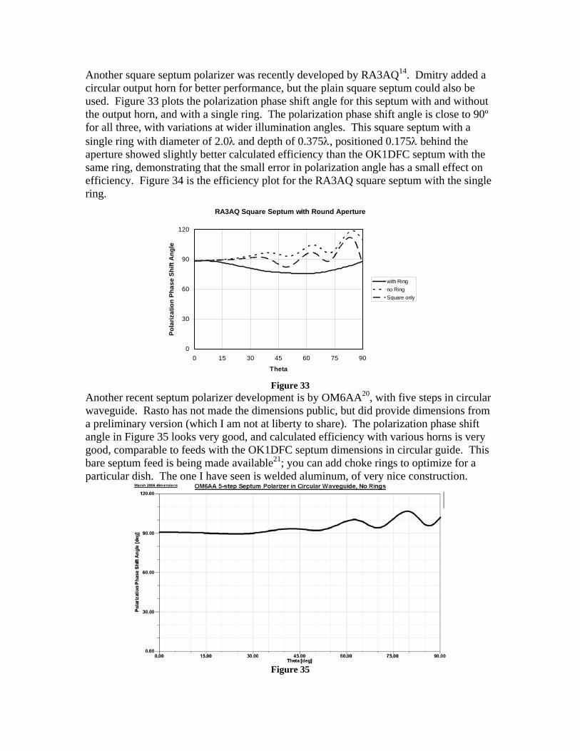
Another square septum polarizer was recently developed by RA3AQ14. Dmitry added a circular output horn for better performance, but the plain square septum could also be used. Figure 33 plots the polarization phase shift angle for this septum with and without the output horn, and with a single ring. The polarization phase shift angle is close to 90º for all three, with variations at wider illumination angles. This square septum with a single ring with diameter of 2.0λ and depth of 0.375λ, positioned 0.175λ behind the aperture showed slightly better calculated efficiency than the OK1DFC septum with the same ring, demonstrating that the small error in polarization angle has a small effect on efficiency. Figure 34 is the efficiency plot for the RA3AQ square septum with the single ring.
RA3AQ Square Septum with Round Aperture
0
30
60
90
120
0 15 30 45 60 75 90
Theta
Pola
rizat
ion
Phas
e Sh
ift A
ngle
with Ringno RingSquare only
Figure 33
Another recent septum polarizer development is by OM6AA20, with five steps in circular waveguide. Rasto has not made the dimensions public, but did provide dimensions from a preliminary version (which I am not at liberty to share). The polarization phase shift angle in Figure 35 looks very good, and calculated efficiency with various horns is very good, comparable to feeds with the OK1DFC septum dimensions in circular guide. This bare septum feed is being made available21; you can add choke rings to optimize for a particular dish. The one I have seen is welded aluminum, of very nice construction.
Figure 35

Figure 34 - Square septum feed, RA3AQ septum dimensions
with choke ring 2.0λ dia x 0.375λ deep, back 0.175λ, RHCP
Dish diameter = 20 λ Feed diameter = 1.7 λ
E&H-plane
45° plane
0 dB -10 -20 -30
Fee
d R
adia
tio
n P
atte
rn
W1GHZ 2007
0 10 20 30 40 50 60 70 80 90-90
-67.5
-45
-22.5
0
22.5
45
67.5
90
Rotation Angle aroundF
eed
Ph
ase
An
gle
E-plane
H-plane
specifiedPhase Center = 0 λ beyond aperture
0.3 0.4 0.5 0.6 0.7 0.8 0.90.25
10
20
30
40
50
60
70
80
90
1 dB
2 dB
3 dB
4 dB
5 dB
6 dB
7 dB8 dB
MAX Possible Efficiency with XPOL loss & Phase error
REAL WORLD at least 15% lower
MAX Possible Efficiency without XPOL or Phase error
MAX Efficiency with phase error ONLYIllumination
Spillover
AFTER LOSSES:
Feed Blockage
Parabolic Dish f/D
Par
abo
lic D
ish
Eff
icie
ncy
%

Both RA3AQ and OM6AA have access to modern electromagnetic simulation software like Ansoft HFSS, and were able to use it to analyze and optimize septum polarizers. They have achieved good circular polarization with improved isolation. At the same time, WD5AGO has been attempting to optimize a septum polarizer empirically – he is only able to measure return loss and optimization. The result is a polarizer with improved isolation but not very good polarization phase shift angle, as shown in Figure 36. Even so, the calculated dish efficiency is still good – the loss from polarization error is not huge.
WD5AGO round septum Chaparral feed for 5760 MHz
0
30
60
90
120
150
0 15 30 45 60 75 90
Theta
Pola
rizat
ion
Phas
e Sh
ift A
ngle
4 steps5 steps
Figure 36
The point of examining polarization phase shift angle is not that it is critical, but that it offers a clear comparison of different septum polarizers. Before, there was only one choice; now there are five good septum choices:
1. OK1DFC in square waveguide – proven performance, but imperfect circular polarization.
2. OK1DFC in circular waveguide – proven performance, good circular polarization. 3. Bornemann in square waveguide – excellent circular polarization with thicker
septum. 4. RA3AQ in square waveguide – excellent circular polarization with improved
isolation. Transition to circular waveguide makes it usable with better horns, and with dual-mode horn for higher f/D.
5. OM6AA in round waveguide – excellent circular polarization with improved isolation.
For those who lack the facilities or inclination to build their own feed, OK1DFC and OM6AA both offer feeds for several bands.

Choke Ring Position Whichever polarizer we choose, a choke ring or multiple rings can improve performance. The single super-VE4MA ring works well for f/D around 0.37, but not for deeper dishes. Other choices are degraded at ring positions favoring smaller f/D. OM6AA also noted18 the effect of ring position on circularity. We shall examine Rasto’s Chaparral-style horn since it seems to offer good performance over a wider f/D range than most, as we saw in Figure 18. In Figure 37, the effect of ring position on the polarization phase shift angle is small until the rings are more than 0.25λ behind the rim – and the efficiency starts dropping at this point also.
OK1DFC Square Septum with OM6AA 3-Ring ChaparralPolarization Rotation Angle vs Ring Position
0
30
60
90
120
0 15 30 45 60 75 90
Theta (deg)
Pol
ariz
atio
n Ro
tatio
n A
ngle
(deg
)
Flush
Back 0.050
Back 0.150
Back 0.250
Back 0.300
Back 0.350
Figure 37

Summary Addition of a choke ring to the popular OK1DFC square septum feed can improve dish efficiency significantly. Many copies of this feed are in use already, so adding a choke ring could enhance the performance of these EME stations – circular polarization is an advantage for EME, but not for most other communications. The feed performance is not quite as good as the round septum feeds, the “Super-VE4MA” feed and the best Chaparral-style feeds. For very deep dishes, a Chaparral-style horn with multiple rings is better than a single ring. For a new feedhorn, several good choices are available for septum polarizers, both square and round. Some are available already built. For homebrewing one, we have shown that the polarizer is reasonably broadband, so dimensions may be adjusted slightly to fit available materials, as long as all dimensions are scaled. Also, the septum thickness is not critical. Then a choke ring or rings may be added and adjusted to optimize performance for a particular dish. We have also seen that good circular polarization is harder to realize over the wide illumination angles needed for very deep dishes – best efficiency is realized for f/D ≥ 0.37. However, if you already have a deeper dish operational, there is no reason not to use it and have good results. A final reminder is in order about the need for good contact between the choke ring and the horn. Both WD5AGO and OM6AA stress this point; Tommy states that at least six contact points are needed on a circular horn, while Rasto uses a spring contact. For the square horn, contacts at all four corners and all four sides are probably in order.
References
1. Paul Wade, W1GHZ, & Tommy Henderson, WD5AGO, “High-Efficiency Feeds for Prime-focus Dishes,” Proceedings of Microwave Update 2006, ARRL, 2006, pp. 102-155.
2. B.W. Malowanchuk,VE4MA, “Selection of an Optimum Dish Feed,” Proceedings of the 23rd Conference of the Central States VHF Society, ARRL, 1989, pp. 35-43.
3. Zdenek Samek, OK1DFC, “Feed for Parabolic Dish with Circular Polarization,” 10th International EME Conference 2002, Prague, 2002. www.qsl.net/ok1dfc
4. Zdenek Samek, OK1DFC , “Information and practical hints for the construction of a septum feed,” DUBUS, 1/2003, pp. 39-47.
5. Ming Hui Chen, G. N. Tsandoulas; A wide-band square-waveguide array polarizer, IEEE Transactions on Antennas and Propagation, vol. 21, pp. 389-391, May 1973.

6. A.W. Love, “The Diagonal Horn Antenna,” Microwave Journal, March 1962, pp. 117-122. (reprinted in A.W. Love, Electromagnetic Horn Antennas, IEEE, 1976, pp. 189-194.)
7. R. Miller, N7ART, “A 23cm Diagonal Waveguide Feed,” DUBUS, 2/1997, pp. 5-14.
8. P. Wade, W1GHZ, The W1GHZ Microwave Antenna Book – Online, Section 6.5.3, www.w1ghz.org
9. C.C. Cutler, “Parabolic-Antenna Design for Microwaves, Proceedings of the IRE, Nov. 1947, pp. 1284-1294. (reprinted in A.W. Love, Reflector Antennas, IEEE, 1978, pp. 16-26.)
10. B. Larkin, W7PUA, “Dipole-Reflector Parabolic Dish Feeds for f/D of 0.2-0.4,” QEX, February 1996, pp. 3-11.
11. P. Wade, W1GHZ, “Analysis of the OK1DFC Septum Feed,” DUBUS, 1/2003, pp. 22-38.
12. www.ansoft.com 13. www.ok1dfc.com/eme/Technic/septum/3cmsept.pdf 14. Dmitry Dmitriev, RA3AQ, “Improved Septum with Dual Mode Horn”
http://www.ok1dfc.com/EME/technic/septum/ra3aq-23-13.pdf http://www.ok1dfc.com/EME/technic/septum/ra3aq.pdf
http://www.vhfdx.ru (in Russian) 15. Rastislav Galuscak, OM6AA, “Septum Feed Revisited,” DUBUS, 4/2004, pp.
11-30. http://www.attplus.cz/hamradio/projekty/article/Septum_feed_revisited.pdf
16. J.S. Hollis, T.J. Lyon, & L. Clayton, Jr., “Microwave Antenna Measurements,” Scientific-Atlanta, July, 1970, p. 10-13.
17. D. Turrin, W2IMU, “A Circularly Polarized Feed Antenna for 1296 mc/s,” Crawford Hill Technical Report #9, December 1971. (reprinted in Proceedings of Microwave Update ’99, ARRL, 1999, pp. 487-491.)
18. Rastislav Galuscak – OM6AA, & Pavel Hazdra, “Circular Polarization and Polarization Losses,” DUBUS, 4/2006, pp. 8-23. http://www.attplus.cz/hamradio/projekty/article/cppl_b.pdf
19. J. Bornemann & V.A. Labay, “Ridge Waveguide Polarizer with Finite and Stepped-Thickness Septum,” IEEE Transactions on Microwave Theory and Techniques, August 1995, pp. 1782-1787.
20. Rastislav Galuscak – OM6AA, & Pavel Hazdra, “Prime-focus circular waveguide feed with septum polarization transformer,” DUBUS, 1/2007, pp. 8-32.
21. http://www.attplus.cz/pdf/en/sf/sf23aaeng.pdf

Appendix
OK1DFC Square septum feed with round choke ringRing 0.05 wavelengths behind aperture
EfficiencyDIA 1.5 1.7 1.9 2.0 2.1 2.2 2.3 2.5
DEEP0.2
0.250.3 67.4 68.6
0.35 64.6 69.9 70.10.4 66.8 46.3
0.450.5
f/DDIA 1.5 1.7 1.9 2.0 2.1 2.2 2.3 2.5
DEEP0.2
0.250.3 0.44 0.44
0.35 0.43 0.43 0.430.4 0.41 0.27
0.450.5
Phase CenterDIA 1.5 1.7 1.9 2.0 2.1 2.2 2.3 2.5
DEEP0.2
0.250.3 -0.26 -0.25
0.35 -0.39 -0.27 -0.230.4 -0.23 -0.05
0.450.5

Appendix
OK1DFC Square septum feed with round choke ringRing 0.10 wavelengths behind aperture
EfficiencyDIA 1.5 1.7 1.8 1.9 2.0 2.1 2.2 2.3
DEEP0.2
0.250.3 70.3
0.35 69.6 72.8 71 70.60.4 67 67 72.3
0.450.5
f/DDIA 1.5 1.7 1.8 1.9 2.0 2.1 2.2 2.3
DEEP0.2
0.250.3 0.42
0.35 0.43 0.42 0.41 0.420.4 0.38 0.37 0.38
0.450.5
Phase Center
DIA 1.5 1.7 1.8 1.9 2.0 2.1 2.2 2.3DEEP
0.20.25
0.3 -0.190.35 -0.37 -0.22 -0.16 -0.11
0.4 -0.21 -0.21 -0.270.45
0.5

Appendix
OK1DFC Square septum feed with round choke ringRing 0.15 wavelengths behind aperture
EfficiencyDIA 1.5 1.7 1.8 1.9 2.0 2.1 2.2 2.3
DEEP0.2
0.25 68.5 69.20.3 66.8 67.2 67 56 63.9 66.2 71.1 69.6
0.35 67.9 67.4 47.7 73.1 72.6 71 70.10.4 64 69.1 67.7 50.1 74.4 65.8 68.8 67.1
0.45 66.8 66.3 73.9 71.7 68.10.5 60.4 62.9 50.5 66.4 62.1
f/DDIA 1.5 1.7 1.8 1.9 2.0 2.1 2.2 2.3
DEEP0.2
0.25 0.43 0.430.3 0.41 0.36 0.37 0.36 0.42 0.42 0.41 0.42
0.35 0.37 0.36 0.27 0.38 0.38 0.42 0.410.4 0.35 0.35 0.33 0.38 0.36 0.36 0.38 0.41
0.45 0.32 0.31 0.35 0.36 0.370.5 0.3 0.32 0.36 0.36 0.38
Phase CenterDIA 1.5 1.7 1.8 1.9 2.0 2.1 2.2 2.3
DEEP0.2
0.25 -0.21 -0.190.3 -0.16 -0.18 -0.14 -0.13 -0.4 -0.23 -0.13 -0.1
0.35 -0.18 -0.18 -0.17 -0.22 -0.1 -0.06 00.4 -0.17 -0.18 0.03 -0.48 -0.05 0.13 0.05 0.13
0.45 -0.14 -0.16 0.11 0.2 0.270.5 -0.03 0.085 0.3 0.38 0.3

Appendix
OK1DFC Square septum feed with round choke ringRing 0.20 wavelengths behind aperture
EfficiencyDIA 1.5 1.7 1.8 1.9 2.0 2.1 2.2 2.3
DEEP
0.20.25 51.9 68.7 70.1 69.8
0.3 67 53.9 71.1 72.4 700.35 68.2 67.2 42.1 74.5 71.8 69.5
0.4 67.9 67.1 70 72.3 69.5 67.10.45 72.7 69.4
0.5
f/DDIA 1.5 1.7 1.8 1.9 2.0 2.1 2.2 2.3
DEEP0.2
0.25 0.42 0.42 0.41 0.420.3 0.35 0.3 0.39 0.38 0.41
0.35 0.36 0.32 0.32 0.37 0.37 0.380.4 0.32 0.3 0.37 0.35 0.36 0.37
0.45 0.36 0.350.5
Phase Center
DIA 1.5 1.7 1.8 1.9 2.0 2.1 2.2 2.3DEEP
0.20.25 -0.35 -0.21 -0.14 -0.13
0.3 -0.14 -0.15 -0.19 -0.07 -0.050.35 -0.16 -0.17 -0.37 0.01 0.05 0.05
0.4 -0.12 -0.11 0.26 0.19 0.18 0.180.45 0.27 0.3
0.5

Appendix
OK1DFC Square septum feed with round choke ringRing 0.25 wavelengths behind aperture
EfficiencyDIA 1.5 1.7 1.8 1.9 2.0 2.1 2.2 2.3
DEEP0.2 48 60.5
0.25 57.2 59.4 70.6 70.20.3 67.2 66.9 49.9 72.9 70.3 70.2 67.8
0.35 67.1 59.6 72.9 70.2 68.40.4 65.2 64.4 70.2 70 64.9 66 62.6
0.450.5 61.2 65.8 59.7 58.2
f/DDIA 1.5 1.7 1.9 2 2.1 2.2 2.3
DEEP0.2 0.36 0.42
0.25 0.3 0.41 0.4 0.390.3 0.32 0.32 0.27 0.37 0.36 0.36 0.38
0.35 0.3 0.36 0.36 0.36 0.360.4 0.3 0.29 0.37 0.36 0.36 0.35 0.35
0.450.5 0.35 0.35 0.37 0.35
Phase Center
DIA 1.5 1.7 1.9 2 2.1 2.2 2.3DEEP
0.2 -0.14 -0.19 -0.270.25 -0.3 -0.1 -0.07
0.3 -0.14 -0.14 -0.24 0.04 0.08 0.03 0.040.35 -0.09 0.34 0.17 0.15 0.12
0.4 0.1 0.15 0.3 0.22 0.27 0.2 0.210.45
0.5 0.18 0.26 0.27 0.16
Appendix
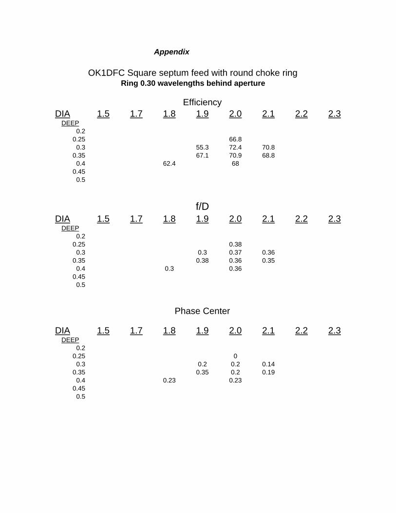
OK1DFC Square septum feed with round choke ringRing 0.30 wavelengths behind aperture
EfficiencyDIA 1.5 1.7 1.8 1.9 2.0 2.1 2.2 2.3
DEEP0.2
0.25 66.80.3 55.3 72.4 70.8
0.35 67.1 70.9 68.80.4 62.4 68
0.450.5
f/DDIA 1.5 1.7 1.8 1.9 2.0 2.1 2.2 2.3
DEEP0.2
0.25 0.380.3 0.3 0.37 0.36
0.35 0.38 0.36 0.350.4 0.3 0.36
0.450.5
Phase Center
DIA 1.5 1.7 1.8 1.9 2.0 2.1 2.2 2.3DEEP
0.20.25 0
0.3 0.2 0.2 0.140.35 0.35 0.2 0.19
0.4 0.23 0.230.45
0.5

Appendix
OK1DFC Square septum feed with round choke ringRing 0.35 wavelengths behind aperture
EfficiencyDIA 1.5 1.7 1.8 1.9 2.0 2.1 2.2 2.3
DEEP
0.20.25 69.9
0.3 71.3 68.2 68.40.35 68.3
0.4 65.7 64.60.45
0.5
f/DDIA 1.5 1.7 1.8 1.9 2.0 2.1 2.2 2.3
DEEP0.2
0.25 0.370.3 0.36 0.35 0.36
0.35 0.360.4 0.36 0.36
0.450.5
Phase Center
DIA 1.5 1.7 1.8 1.9 2.0 2.1 2.2 2.3DEEP
0.20.25 0.09
0.3 0.18 0.17 0.130.35 0.22
0.4 0.18 0.190.45
0.5