enhancing shear and bearing strength of wood i-joists ... · enhancing shear and bearing strengths...
TRANSCRIPT

Enhancing Shear and Bearing Strength of Wood I-joists
Project No. UNB3
Value to Wood No. UNB3
Research Report 2005
by
Y. H. Chui Director and Professor
Ghulam Pirzada
Post-doctoral Scientist
and
Shouyong Lai Graduate Research Assistant
Wood Science and Technology Centre
Faculty of Forestry and Environmental Management University of New Brunswick
April 2005
This report was produced as part of the Value to Wood Program, funded by Natural Resources Canada

Project No. UNB3
Value to Wood No. 3
Research Report 2005
Enhancing Shear and Bearing Strength of Wood I-joists
by
Y. H. Chui Director and Professor
Ghulam Pirzada
Post-doctoral Scientist
and
Shouyong Lai Graduate Research Assistant
Wood Science and Technology Centre
Faculty of Forestry and Environmental Management University of New Brunswick
April 2005
Project Leader Reviewed by Department Manager

Enhancing shear and bearing strengths of wood I-joists
Notice This report was prepared with financial assistance from the Canadian Forest Service, Natural Resources Canada. No part of this report may be reproduced, stored in a retrieval system or transmitted, in any form or by any means, without the prior written consent of the University of New Brunswick If cited in whole or in part, acknowledgement of the source and the authors would be appreciated. Neither the University of New Brunswick nor the authors (or any other persons acting on their behalf) make any warranty, express or implied, or assume any legal responsibility or liability for the completeness of any information, apparatus, product or process disclosed, or represent that the use of the disclosed information would not infringe upon privately owned rights, or represent that the disclosed information is fit for a particular purpose. Any reference in this report to any specific commercial product, process or service by trade name, trade mark, manufacturer or otherwise does not constitute or imply its endorsement by the University of New Brunswick. This report is designed to provide accurate, authoritative information but it is not intended to provide professional advice. If such advice is sought, then services of University of New Brunswick professional could be retained. © 2003, 2004 University of New Brunswick All rights reserved.

Enhancing shear and bearing strengths of wood I-joists
1 of 78
Abstract This project studies the influence of component geometry and properties on bearing failure (knife-through) in flange of wood I-joist and load-carrying capacity of wood I-joist with a web hole. The project goal was achieved by a combination of numerical modelling and experiments. Experimental work included testing of wood I-joist specimens under bearing, testing of full-size I-joist with single and double web holes and testing of I-joist component materials (lumber and oriented strand board) to develop a material property data base. Finite element models were developed for calculating the stresses in the component materials of wood I-joists when loaded under bearing and under transverse loading with holes in the web. A fracture mechanics based approach was adopted to predict failure load under these loading conditions. It was found that the proposed modelling approach provides fairly accurate predictions of knife-through failure load. Modelling results show that there is an optimum flange-web joint profile that maximizes the resistance against knife-through failure. Growth ring orientation in flange lumber was also found to influence knife-through failure. For the investigation on strength of wood I-joist with web holes, it was found that the proposed modelling approach produces accurate prediction of failure load for I-joist with a square hole but under-estimates that for I-joist with a circular hole. It was shown that the model can be a useful tool to investigate the relative influence of component properties and geometry on load-carrying capacity wood I-joist, leading to recommendations on reducing the testing requirements during product qualification. Test results revealed that the influence of bending moment needs to be accounted for when evaluating the safe size or location of a web hole. A designer useable method was also developed which, with further calibration and simplification, can be adopted as a useful design tool.
Key words : Wood I-joist, bearing strength, shear strength, flange-web joint, web opening, finite element modelling, fracture mechanics

Enhancing shear and bearing strengths of wood I-joists
2 of 78
Acknowledgements The University of New Brunswick wishes to acknowledge the financial support of Natural Resources Canada to this research project. Thanks are also due to industry liaisons, Pierre Audet, Boise Cascade AllJoist and Darian Wentland and Ken Koo of Jager Building Systems, for their support and technical advice. The following companies assisted with fabrication of I-joists:
- Boise Cascade AllJoist, St Jacques, New Brunswick - Norbord Inc. (I-joists), Juniper, New Brunswick
The contribution of processing and staff time to this project from these companies is gratefully acknowledged. Staff
- Dr. Y. H. Chui, Project Leader - Ghulam Pirzada, Postdoctoral Scientist - Shouyong Lai, Graduate Research Assistant - Andrew Sutherland, Equipment Officer - Dean McCarthy, Technician - Donny Johnson, Technician - Corey Arbreau, Technician - Dave Doherty, Technician

Enhancing shear and bearing strengths of wood I-joists
3 of 78
Table of contents Abstract .........................................................................................................................................................1 Acknowledgements........................................................................................................................................2 Staff ...............................................................................................................................................................2 Table of contents ...........................................................................................................................................3 1 Objectives ...............................................................................................................................................5 2 Introduction .............................................................................................................................................5 3 Bearing Strength of Wood I-Joist ............................................................................................................6
3.1 Objectives .......................................................................................................................................6 3.2 Literature review .............................................................................................................................6
3.2.1 Material properties of typical flange, web and glue and prediction of material failure.........6 3.2.2 Flange-glue-web interaction...............................................................................................8 3.2.3 Summary of literature review .............................................................................................9
3.3 Survey of the industry of flange-web profile ....................................................................................9 3.4 Development of finite element model ..............................................................................................9 3.5 Material test program ....................................................................................................................13
3.5.1 Lumber properties............................................................................................................13 3.5.2 OSB properties ................................................................................................................15
3.5.2.1 Vibration test to determine edgewise bending and shear moduli of OSB ...........16 3.5.2.2 Flatwise bending test ..........................................................................................17 3.5.2.3 Tension test ........................................................................................................17 3.5.2.4 Compression test ................................................................................................18 3.5.2.5 Two-rail shear .....................................................................................................19 3.5.2.6 Fracture energy test............................................................................................19
3.6 Wood I-joist bearing tests..............................................................................................................21 3.7 Application of fracture mechanics approach to predict knife-through failure .................................25 3.8 Sensitivity analysis and selection of an optimum flange-web joint profile......................................27 3.9 Discussion of modeling techniques and future work .....................................................................29
4 Analysis of Wood I-joist With Web Holes ..............................................................................................31 4.1 Objectives .....................................................................................................................................31 4.2 Literature review ...........................................................................................................................31
4.2.1 Standards documents for wood I-joist ..............................................................................31 4.2.2 Research studies on wood I-joists with web holes..............................................................32 4.2.3 Non-wood I-joists with web holes.....................................................................................37 4.2.4 Summary of literature review ...........................................................................................38
4.3 Testing of wood I-joists with web holes .........................................................................................39 4.3.1 Effect of hole shape and size...........................................................................................39 4.3.2 Effect of bending (specimen length).................................................................................40 4.3.3 Effect of distance between adjacent web holes ...............................................................41
4.4 Test Results and Discussion.........................................................................................................42 4.4.1 Effect of web hole size and shape ...................................................................................42

Enhancing shear and bearing strengths of wood I-joists
4 of 78
4.4.2 Effect of bending moment ................................................................................................45 4.4.3 Interaction of web holes in I-joists containing two web holes ...........................................47
4.5 Material test program ....................................................................................................................49 4.6 Development of simplified calculation procedure for peak stress at the boundary of a web hole..49 4.7 Development of finite element models for calculating stresses at boundary of web hole..............52
4.7.1 Finite element model for web with a circular hole ............................................................52 4.7.2 Finite element model for web with a square hole ...............................................................52
4.8 Application of FAM to predict fracture load ...................................................................................53 4.9 Verification of proposed strength prediction methods ...................................................................55 4.10 Sensitivity analysis ........................................................................................................................59
4.10.1 Influence of flange MOE on failure load ...........................................................................59 4.10.2 Influence of web MOE on failure load of I-joist with a web hole .......................................62 4.10.3 Influence of spacing between adjacent holes - double hole analysis ...............................64
5 Conclusions ..........................................................................................................................................67 6 Next Steps ............................................................................................................................................68 7 References............................................................................................................................................68 Appendix I - COMMERCIAL FLANGE-WEB JOINT PROFILE GEOMETRIES ...........................................72

Enhancing shear and bearing strengths of wood I-joists
5 of 78
1 Objectives The ultimate goal of this project is to improve the design of a value-added wood product leading to enhanced performance in service, thereby allowing the wood I-joist industry to maintain its growth and expand its market share. Specific objectives of the project are: • To understand the influence of web-flange joint profile on bearing strength of I-joist, leading
to optimum profile and material selection. • To evaluate the influence of web hole shape and size, and component properties on strengths
of I-joist with a web hole. • To develop a model for predicting strength of I-joist with a web hole. 2 Introduction The wood I-joist industry is one of the fastest growing sectors in forestry in the past few years. Over 80% of the current production is used in residential floor construction, and it is estimated that the current share of the residential floor construction market in North America is about 50% (Shuler and Adair 2003). The industry feels that the product has somewhat reached maturity in the residential construction market. Future expansion of the industry will likely hinge on its ability to penetrate into the non-residential floor construction market, for which design loads are generally higher. For residential construction, the critical joist properties are bending strength and stiffness. For non-residential construction however, other properties such as shear and bearing strengths may be the controlling property due to the higher loading. Tests have shown that premature bearing failure at a joist end could occur due to ‘cutting’ of the web through the bottom flange. It is felt that higher bearing capacity could be achieved by suppressing this type of failure. In addition, openings in the web of a joist are often made at building sites to provide passage for service ducts and pipes. The impact of web opening on strength properties of wood I-joist is not fully understood and current design specifications dealing with web openings are empirical in nature. This project will lead to a better understanding of the influence of material properties and component geometry on bearing and shear strengths of I-joists, leading to improved design properties for wood I-joists. This project comprises two sub-projects dealing with bearing strength and influence of web hole on strength properties of I-joist respectively. Research approach for each sub-project is summarized below. Bearing strength
1. Survey of industry of common flange-web joint profiles. 1 Development of a finite element model for predicting knife-through failure of I-joist
under bearing load.

Enhancing shear and bearing strengths of wood I-joists
6 of 78
2 Testing of component materials and wood I-joists to verify the predictive capability of the model.
3 Identification of optimum flange-web joint profile that provides maximum resistance to knife-through failure.
Influence of web opening
1. Development of a simplified design model and finite element model to predict strength of wood I-joists with circular or square web hole.
2. Testing of wood I-joists with single and double web hole to verify the developed models.
3. Sensitivity analysis to evaluate the influence of web hole size, distance between web holess and component properties on strength strengths of I-joists.
3 Bearing Strength of Wood I-Joist 3.1 Objectives For wood I-joists made with solid sawn lumber flanges, particularly with low wood density, the so-called knife through failure under bearing is often the dominant bearing failure mode at the support. This action results in the web cutting through the flange material perpendicular to the grain. The present study seeks to explore the mechanism of fracture process of the flange material and quantify the knife-through failure load. The key objectives of this part of the study are to:
• Develop a reliable finite element model for predicting stress distribution under loads • Recommend an optimal flange-web joint profile reflecting the appropriate material
properties 3.2 Literature review The research team has not been able to identify literature directly dealing with knife-through failure. However a literature review was performed on two related aspects:
• Material properties of typical flange, web and glue materials and prediction of failure in these materials;
• Interaction behaviour between flange, web and glue. 3.2.1 Material properties of typical flange, web and glue
and prediction of material failure The type of I-joist that is of interest here is made of solid lumber flanges since it is known that knife-through failure rarely occurs in I-joists with laminated veneer lumber (LVL) flanges. The properties of lumber flange material are influenced by the wood structure. Wood itself is a

Enhancing shear and bearing strengths of wood I-joists
7 of 78
natural cellular, polymeric composite with a microstructure of biological origin. The complex and heterogeneous structure of wood may be represented by three principal directions, namely longitudinal (L), radial (R) and tangential (T). The modulus of elasticity along the grain, EL, has the highest value and the ratios ET/EL and ER/EL are respectively 0.041and 0.074 (Gerald et al 1991, Smith et al 2003). In practice, however, solid wood products often contain growth rings which do not align perfectly parallel to either tangential or radial direction (Bodig and Jayne 1982, Forest Products Laboratory 1999).
Since the interest in this study is to predict the so-called knife-through failure in lumber flange of I-joists, a review on papers dealing with failure prediction of wood material is presented here. In general failure of wood is a complex phenomenon. Not only does the L-R-T orientations to a large extent dictate the response of lumber under the action of a load, the presence of growth defects, such as knots, checks and shakes, steers the material response away from known standard conclusions. It is this difficulty that an array of stress-strain relationships (Gerald et al 1991) was suggested to represent the material behaviour in the past, but with varying degrees of success. This presents extreme difficulties when attempting to predict failure load of a material or system that causes fracture of the material.
In the last few decades more rational approaches for predicting material failure in solid wood have emerged in the literature (Bodig and Jayne 1982, Forest Products Laboratory 1999, Bostrom 1992, Davids et al 2003). Two methodologies were adopted from studies dealing with other materials for predicting failure load and after-fracture behaviour of a material. In one approach the concepts of linear or non-linear elasticity and linear-elastic fracture mechanics are blended (Bostrom 1992). In the other approach, lattice models are used (Davids et al 2003). In the lattice material model, the material is represented by an array or lattice of interconnected discrete bar elements. Element properties are assigned based on a calibration to the micro-structural properties of the wood. Through the application of the lattice model, Davids et al (2003) was able to demonstrate that reliable prediction of the fracture process of a wood specimen can be achieved.
The web in wood I-joists is commonly made of oriented strand board (OSB). OSB is an engineered structural panel composed of flakes or strands sliced from logs. The Structural Board Association (SBA) has published strength and stiffness properties of OSB conforming to CSA O437 (CSA 2001). The published values of moduli of elasticity in the major and minor axes are 5500 MPa and 1500 MPa respectively (SBA 2002). Data on edgewise modulus of elasticity is not included in any CSA standard (CSA 2001) nor the SBA Technical Bulletin (SBA 2002), and yet this information is critical for evaluating the bearing and shear strengths of wood I-joists as will be discussed later. However through-thickness shear modulus information is available in Smith et al (2003), which gives shear modulus through-thickness (edgewise) as 1240 - 2000 MPa. Wang and Cheng (1995) also found similar shear modulus value. Morris et al (1996) conducted tests to determine fracture energy of OSB, which appears to be the only information of its kind in the literature. These tests were part of a material test program to determine material

Enhancing shear and bearing strengths of wood I-joists
8 of 78
properties for predicting failure load of I-joist with a web hole. They found that the fracture energy Gf for a 12.5mm thick OSB is 5119 J/m2 and 3964 J/m2 parallel and perpendicular to the major axis respectively.
Glue, as an adhesive bonding material, has been used to join substances since the start of early civilization. In the present context, the wood industry is one of the major users of this material. A wide range of glues have been developed and are being used today that meet different levels of in-service performance requirement. From a structural standpoint, in addition to strength and stiffness, the ductility of a glue is also a critical property. Commonly used industrial adhesives like PRF (Phenol-resorcinol-formaldehyde), PUR (Polyurethane) and PVAc (Polyvinyl acetate-based) are known to cover a range of strength and ductility. The modulus of elasticity values for polymer adhesives like epoxy and phenolics are listed as 2410 MPa and 2760 - 4830 MPa respectively (Callister 2003). It would therefore be reasonable to assume a value of 3000 - 3500 MPa for structural adhesives. It should be realized that test methods for determining glue elastic properties are not yet fully standardized (Edogan and Ratwani 1971) and therefore it is unclear if published mechanical properties for various glue materials are reliable.
3.2.2 Flange-glue-web interaction ASTM D5055 (2003a) provides guidelines for performing tests on wood I-joists to determine design bearing strength of wood I-joists. Under this test a number of failure modes are possible. Experience of the authors is that certain I-joist manufacturers tend to have predominantly knife-through failure whereas others do not. The mode of failure is likely linked to the web-flange profile and component properties. A parallel search on glued wood joint has resulted in two principal papers by Milner and Yeoh (1991) and Jauslin et al (1995) on stress analysis of bonded wood joints. These studies showed that high stress concentration occurs at regions of abrupt discontinuity such as the tip in a finger joint and that the tip width has a greater effect on strength than the total glued area. Concepts of linear and non-linear elasticity and a blend of linear elastic fracture mechanics or nonlinear fracture mechanics have been applied to predict failure loads for glued lumber (Bostrom 1992, Wernersson 1994, Serrano 1997, 2000). These studies were mainly related to softening behaviour of solid wood and fracture energy evaluations and in the application of the fracture mechanics principles. Some reliability-based work related to behaviour of wood I-joists under bending has also been performed (Foschi and Yao 1993, Sharp et al 2000). Sharp et al (2000) applied the Weibull weakest link theory to compute the effect of length on moment capacity of wood I-joists. A reliability-based analysis of wood I-joists that takes into account multiple failure modes was conducted by Foschi and Yao (1993). Foschi and Yao (1993) concluded that the flange-to-web and web shear failure modes were more critical than other modes of failure. For prediction of knife-through failure in lumber, it is expected that the use of fracture mechanics approach can provide acceptable solutions. This will be attempted in this study. Landelius (1989) has proposed an approach, known as the finite area method (FAM), to predict fracture behaviour in wood, which appears to be suited to predict knife-through failure mode. The finite area

Enhancing shear and bearing strengths of wood I-joists
9 of 78
method incorporates the principles of linear elastic fracture mechanics (LEFM) and mean stress theory.
3.2.3 Summary of literature review It is clear from the literature review that no prior research study has been conducted on evaluating bearing failure of wood I-joists. Since this project will attempt to apply fracture mechanics to predict knife-through failure in lumber flanges of wood I-joists under bearing load, some of the previous research on applying fracture mechanics approach to predict failure of wood components was reviewed. Generally it has been shown that the application of fracture mechanics principle to predict failure of glued wood products has provided reasonable prediction of load-carrying capacity of engineered wood products. In this study therefore models will be developed to predict knife-through failure in flange material of a wood I-joist. 3.3 Survey of the industry of flange-web profile
To obtain information on typical flange-web joint profile used by the I-joist industry, a number of companies and research organizations were contacted and replies from one research organization and 3 manufacturers were received. These contacts have revealed that the types of flange-web profile fall into two categories: single-tip and two-prong. The survey yielded 3 single-tip and 2 two-prong flange-web joint profiles. The three single-tip profiles were similar and are shown in Appendix I as WF-PROF1, WF-PROF2 and WF-PROF3 respectively. A two-prong profile was developed by Forintek Canada Corp, and a second one is currently used by a manufacturer. The Forintek profile however has not been used in commercial production. A simplified version of the two-prong profile, which was analyzed in an earlier study is presented as TWF-PROF in Appendix I. This simplified version was used to get a preliminary indication as to whether there are significant differences in stress distributions between single-tip and two-prong profiles. It can be concluded from this survey and from general observations that the predominant commercial profiles belong to the single-tip category. Discussion with one manufacturer who currently uses a two-prong profile has revealed that the two-prong profile was initially developed to allow manual handling of assembled I-joists in a manufacturing facility prior to curing of glue. This factor was important when the industry was not as automated as in most contemporary manufacturing systems. It is likely that the two-prong profiles will be gradually phased out in the future as more automation and fast-curing adhesives are adopted by the industry. 3.4 Development of finite element model An I-joist with a vertical load applied at a support can be modeled as a two-dimensional cross section as shown in Figure 3.1. Because of symmetry, only the shaded region needs to be considered in the analysis.

Enhancing shear and bearing strengths of wood I-joists
. The shaded part in Figdistribution using a finSAP2000 commercial joint profile is presentewidth and web projectwidth at the bearing suby discretizing the planThe quadrilateral elemeA typical four-node ele
Figure 3.1 I-joist cross-section under a vertical load
ure 3.1 is discretized into a suitable mesh for the determination of stress ite element program. The finite element modeling is performed using
finite element programming package. A detailed view of the flange-web d in Figure 3.2, where WB, WT and WP denote web tip width, web top ion into flange respectively. WF and HF denote respectively the flange pport and the height of the flange. Mesh generation is then accomplished e area bounded by the blue lines in Figure 3.2 into quadrilateral elements. nt used is a 4-noded element with three degrees-of-freedom at each node. ment with direction of stresses acting on it is presented in Figure 3.3.
WT
WB
WP
WF
HF
.
Figure 3.2 Flange-web joint profile – definition of symbols10 of 78

Enhancing shear and bearing strengths of wood I-joists
Node
σ x X
Y σ y τxy
4-noded
F
In Figure 3.3 tangential (shethis study:
(a) A meshstresseformul
(b) A finerof re-eelemen
The mesh fodistribution at
igure 3.3 A four-node finite element and sign convention for stressesacting on it.
11 of 78
σx and σy are normal stresses in X and Y directions respectively while τxy is a ar) stress in X-Y plane. Two schemes of finite element discretization are used in
in which stress concentration at a re-entrant corner is ignored. In this case the s converge elsewhere and approximately 4000 elements are used in this ation. mesh is used in this case to account for sudden jumps in stresses at the locations ntrant corners and other critical locations. This formulation, using about 12000 ts, is adopted to compute stresses for fracture modeling.
r scheme (b) is illustrated in Figure 3.4 and typical principal tensile stress the location of bottom flange-groove re-entrant is shown in Figure 3.5.

Enhancing shear and bearing strengths of wood I-joists
12 of 78
Figure 3.4 Model showing mesh generation of scheme (b).
Figure 3.5 Typical principal tensile stress distribution at the
bottom of flange groove re-entrant corner.

Enhancing shear and bearing strengths of wood I-joists
3.5 Material test program In order to evaluate the validity of the developed finite element model, a comparison of the model prediction with the test results is imperative. This requires the generation of material properties to be used as input into the finite element model. The tests were performed for the two principal materials namely lumber and OSB. Some of the material properties discussed in this section were also used in the analysis for I-joist with web holes, as described in Section 4.
3.5.1 Lumber properties Lumber property evaluation focused on the determination of mechanical properties in the radial and tangential directions. This was done mainly due to two principal reasons:
(a) The behaviour of bearing is generally marked by two distinct failure modes: • a gradual failure when growth rings are perpendicular to loading direction (Figure
3.6), and ultimately fracture with the crack running perpendicular to the growth ring (Figure 3.7, right).
• an abrupt failure when growth rings are parallel to the loading direction, with the crack running parallel to the growth and along the boundary between latewood and earlywood (Figure 3.7, left).
(b) Anticipated application of fracture mechanics principles to assess and predict bearing failure requires the determination of fracture energy information of the lumber in strictly radial or tangential direction.
Crushing of earlywood
F
igure 3.6 Bearing failure in the earlywood at the re-entrantcorner.13 of 78

Enhancing shear and bearing strengths of wood I-joists
F
The lumber testto fabricate I-jverification purto producing kn3.1. The tests cobending and fra
Table 3.1 – Lum
Properties
Tension perpendicular t
grain Compression
perpendicular tgrain
Bending
Shear strength
Fracture energ
igure 3.7 Cracking pattern of tangential (left) and radial (right)specimens under bearing load through web.
14 of 78
ed in the material test program was red pine lumber. This same material was used oist specimens, which were tested to provide bearing strength data for model poses. Red pine was chosen because of its low wood density which is more prone ife-through failure than denser wood. The lumber test program is shown in Table nducted were tension perpendicular to grain, compression perpendicular to grain,
cture energy. The test results are presented in Tables 3.2 through to 3.6.
ber property test program.
Test method Growth ring orientation Size (mm) Number of
specimens
o ASTM D143 Radial Tangential 50 x 64 x 50 10
10
o ASTM D143 Radial
Tangential 50 x 50 x150 10 10
ASTM D143 Radial Tangential 25 x 25 x 410 10
10
ASTM D143 Radial Tangential 50 x 64 x 150 10
10
y Fracture
energy test method
Radial Tangential 200 x 60 x 60 10
10

Enhancing shear and bearing strengths of wood I-joists
15 of 78
Table 3.2 – Lumber tension test results.
Property Growth Ring Orientation Strength* (MPa) Moisture
content Tensile strength perpendicular
to grain Radial
Tangential 3.34 (0.84) 2.93 (0.6) 12.1%
* Values in parentheses are standard deviations. Table 3.3 – Lumber compression test results.
Property Growth ring orientation Strength* (MPa)
MOE* (MPa)
Moisture content
Compression perpendicular to
grain
Radial Tangential
3.48 (0.9) 3.91 (0.18)
229.9 (48.16) 171.7 (24.42) 12.2%
* Values in parentheses are standard deviations. Table 3.4 – Lumber bending test results.
Property Growth ring orientation
Strength* (MPa) MOE* (MPa) Moisture content
Bending Radial Tangential
66.5 (11.5) 74.8 (11.7)
7952 (1608) 8895 (2311) 11.65%
* Values in parentheses are standard deviations.
Table 3.5 – Lumber shear test results. Property Growth ring orientation Strength* (MPa) Moisture Content
Shear Radial Tangential
6.45 (0.86) 8.64 (0.98) 11.25%
* Values in parentheses are standard deviations. Table 3.6 – Lumber fracture energy test results.
Property Growth ring orientation Fracture energy* (J/m2) Moisture content
Fracture energy
Radial Tangential
240.8 (87) 513.3 (91) 11.9%
* Values in parentheses are standard deviations. From Tables 3.2 to 3.6, it is inconclusive if there is a clear difference between mechanical properties of red pine in the radial and tangential directions. However appropriate mechanical property values for each direction will be used in the modelling.
3.5.2 OSB properties An experimental program for the OSB material was also initiated similar to the lumber test program presented above. The tests performed were as follows:

Enhancing shear and bearing strengths of wood I-joists
16 of 78
1. Edgewise bending and shear moduli in the two principal axes. 2. Shear strengths in the two principal axes. 3. Tensile strength in the two principal axes. 4. Compressive strength in the stronger axis. 5. Fracture energy in the two principal axes.
3.5.2.1 Vibration test to determine edgewise bending and shear
moduli of OSB The vibration test technique developed by Chui and Smith (1990) was used to evaluate bending and shear moduli of web OSB. In this test the beam test specimen is suspended by two springs as shown in Figure 3.8. The specimen is then vibrated by impacting it with an instrumented hammer. The vibration of the beam is recorded by an accelerometer. In this project the hammer impact and vibration signals were recorded and analysed by a spectrum analyzer. The test method is based on the measurement of the first and second natural frequencies of a wooden beam under free vibration. From the first and second natural frequencies, the bending and shear moduli are calculated (Chui and Smith 1990). The thickness of the OSB tested was 9.5mm. OSB specimens were cut from web stock obtained from the wood I-joist manufacturer. The OSB test specimen size was 1200mm x 75mm x 9.5mm. The moisture content of the OSB specimens was about 8.5%. Ten replicates were tested for each of the two face strand orientation groups. Table 3.7 shows the test results for the OSB specimens. Table 3.7 – Summary results of OSB property tests using vibration technique. Face strand orientation MOE (MPa) Shear modulus (MPa) Parallel 5787 (372) 1402 (424) Perpendicular 3101 (113) 1074 (527) * Values in parentheses are standard deviations.
Instrumented hammer Spring
Accelerometer
Spectrum Analyzer
Beam
Figure 3.8 Vibration test set-up.

Enhancing shear and bearing strengths of wood I-joists
17 of 78
3.5.2.2 Flatwise bending test Flatwise bending tests were conducted on OSB specimens to determine their modulus of elasticity and modulus of rupture (MOR). Tests were performed according to method B of ASTM D3043 (2003b). Eight replicates, of dimensions 1200mm x 75mm x 9.5mm, were used for each face strand orientation. Average moisture content of each group was 8.4%. Test results are shown in Table 3.8. Table 3.8 – Summary results of OSB property tests using flatwise bending. Face strand orientation MOE (MPa) MOR (MPa) Parallel 5281 (223) 29.61 (4.51) Perpendicular 3020 (337) 14.87 (1.18) * Values in parentheses are standard deviations. 3.5.2.3 Tension test Tension tests were conducted to estimate the tensile strength of OSB parallel and perpendicular to the face strand direction. The test set-up is illustrated in Figure 3.9. The test procedure followed method B of ASTM D3500 (2003c). Specimen dimensions were 500mm x 50mm x 9.5mm. Ten replicates were used for each face strand direction. A LVDT was used to measure the elongation of the specimen over a gauge length. From the measured load and elongation data, the tensile strength and MOE in tension were calculated. Table 3.9 presents the test results. Average moisture content of the test specimens was about 8.4%. The tension MOE values are similar to those determined above using other techniques. The MOE values are used in determining stress distribution in the joist. Tensile strength data is required for the prediction of failure load using strength theory approaches. It can be noted from Table 3.9 that tensile strength parallel to face strand is about three times that perpendicular to face strand. Figure 3.9 OSB tension test set-up.

Enhancing shear and bearing strengths of wood I-joists
18 of 78
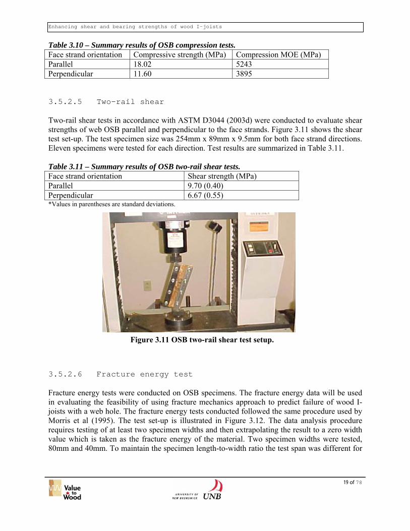
Table 3.9 – Summary results of OSB tension tests. Face strand orientation Tensile strength (MPa) Tension MOE (MPa) Parallel 15.87 (2.68) 5201 (686) Perpendicular 4.47 (0.59) 3459 (306) * Values in parentheses are standard deviations. 3.5.2.4 Compression test As stated above this project evaluates the feasibility of using strength theory to predict failure load. The application of strength theory generally requires a number of strength properties to be known, including shear, tension and compression. Compression tests were conducted to estimate the compressive strength of OSB parallel and perpendicular to the face strand direction. The test set-up is illustrated in Figure 3.10. Test specimens were fabricated by gluing three pieces of OSB pieces to form a specimen of dimensions 177mm x 46mm x 29mm in both directions, parallel and perpendicular to the face strands. This was done to avoid buckling of specimens during testing. Two LVDTs were attached to both sides of a test specimen to measure the deformation. Four built-up replicates were used for each face strand direction. From the measured load and deformation data, the compressive strength and MOE in compression were calculated. Table 3.10 presents the test results. Moisture content of the test specimens was about 8.4%. Reviewing the results in Table 3.10 and those presented in Tables 3.7 to 3.9 shows that the four methods, vibration edgewise, bending flatwise, tension and compression, provide similar MOE values for each face strand direction. For modeling purposes, it appears that MOE values of 5200 MPa and 3400 MPa are appropriate for parallel and perpendicular to face strand direction respectively. The compressive strength parallel to face strand is also substantially higher than that of perpendicular to face strand, although the difference between the two directions is not as large as for tensile strength.
Figure 3.10 OSB compression test set-up.
Enhancing shear and bearing strengths of wood I-joists
19 of 78
Table 3.10 – Summary results of OSB compression tests. Face strand orientation Compressive strength (MPa) Compression MOE (MPa) Parallel 18.02 5243 Perpendicular 11.60 3895 3.5.2.5 Two-rail shear Two-rail shear tests in accordance with ASTM D3044 (2003d) were conducted to evaluate shear strengths of web OSB parallel and perpendicular to the face strands. Figure 3.11 shows the shear test set-up. The test specimen size was 254mm x 89mm x 9.5mm for both face strand directions. Eleven specimens were tested for each direction. Test results are summarized in Table 3.11. Table 3.11 – Summary results of OSB two-rail shear tests. Face strand orientation Shear strength (MPa) Parallel 9.70 (0.40) Perpendicular 6.67 (0.55) *Values in parentheses are standard deviations.
Figure 3.11 OSB two-rail shear test setup. 3.5.2.6 Fracture energy test Fracture energy tests were conducted on OSB specimens. The fracture energy data will be used in evaluating the feasibility of using fracture mechanics approach to predict failure of wood I-joists with a web hole. The fracture energy tests conducted followed the same procedure used by Morris et al (1995). The test set-up is illustrated in Figure 3.12. The data analysis procedure requires testing of at least two specimen widths and then extrapolating the result to a zero width value which is taken as the fracture energy of the material. Two specimen widths were tested, 80mm and 40mm. To maintain the specimen length-to-width ratio the test span was different for

Enhancing shear and bearing strengths of wood I-joists
20 of 78
the two widths. Accordingly, the corresponding specimen sizes were 480mm x 80mm x 9.5mm and 240mm x 40mm x 9.5mm for three face strand orientations, namely parallel to face strands, perpendicular to face strands and at 45° to face strands. Five replicates were tested for each group.
Figure 3.12 Fracture energy test set-up. A typical load versus deformation (cross-head movement) plot is given in Figure 3.13. The fracture energy is calculated from the area under the curve as illustrated in the figure. Test results are summarized in Table 3.12. It can be seen that fracture energy decreases with increasing face strand angle. The fracture energy results for the web stock OSB tested in this study compare well with those (5119 and 3964 J/m2) obtained by Morris et al (1995) for 12mm thick OSB.
-0.05
0
0.05
0.1
0.15
0.2
0.25
0.3
0.35
0 2 4 6 8 10 12 14 16
deformation (mm)
load
(kN
)
∫0
0Pd
δδ
Figure 3.13 Calculation of fracture energy.

Enhancing shear and bearing strengths of wood I-joists
21 of 78
Table 3.12 – Summary results of fracture energy tests.
Fracture energy (J/m2) Face strand orientation Width = 80mm Width = 40mm Width= 0mm
Parallel 5949 5480 5011 Perpendicular 4533 4075 3616 45° 5402 4749 4097 3.6 Wood I-joist bearing tests Wood I-joists were fabricated using an OSB web and red pine lumber flanges at a commercial I-joist plant. Red pine lumber was used because its low density was thought to facilitate knife-through failure under bearing load. The lumber was selected to ensure there was a mixture of flat-sawn and quarter-sawn lumber such that the influence of growth ring orientation on knife-through failure can be evaluated. The depth of the wood I-joist was 302mm (11-7/8 in.). Cross sectional size for the flange was 38mm x 63mm (nominal 2 in. by 3 in.) and the thickness of the web was 9.5 mm. The OSB and lumber materials have already been tested to obtain elastic, strength and fracture properties for the purpose of verifying the predictive models. The wood I-joists were fabricated at an I-joist company in New Brunswick. Full length I-joists were manufactured (14.63 m or 48 ft). This full-length was cut into shorter blocks of 0.1m length. Initially a test set-up using the 0.1m length block, as shown in Figure 3.14 was used. However it was found that, possibly due to twisting of the specimen, bearing failure was not obtained with the test set-up. Instead, web failure in the ‘necking’ region of the web just above the bottom flange occurred.
Stiffener
Clip gauge location
Figure 3.14 Initial bearing test set-up that produces web necking failure.
In order to prevent the unintended failure mode due to possible twisting and out-of-plane deformation, the test set-up was modified. In the modified set-up, each I-joist short block was

Enhancing shear and bearing strengths of wood I-joists
cross-cut at a point approximately 6mm above the flange-web joint to obtain a short test specimen. Figure 3.15 shows the dimensions of the modified bearing test specimen. The web projection was about 6mm and the specimen was reduced to a 42mm width. Figure 3.16 depicts the experimental setup. A universal test machine applied the compressive load. Two clip gauges were mounted on opposite sides of the specimen to record displacements and detect crack initiation. The top of the web tip was coated with an adhesive to prevent crushing of the material under load. The load was applied at a rate of cross-head movement of 0.25 mm/min. The load and the clip gauge readings were recorded by a computer. Two groups of specimens having growth rings oriented parallel and perpendicular to loading direction
ively were tested. respect
64 mm
12 mm
6 mm
38 mm
9.5 mm
6.5 mm
web
flange
Figure 3.15 Dimensions of bearing test specimen.
F
22 of 78
igure 3.16 Modified bearing test set-up.

Enhancing shear and bearing strengths of wood I-joists
23 of 78
For each test group, fifteen specimens were tested. However, only five test specimen of radial orientation and five of the tangential orientation exhibited knife-through failure. Typical failure modes for radial and tangential specimens are illustrated in Figure 3.17 and 3.18 respectively.
Figure 3.17 Radial test specimen after failure.
Figure 3.18 Tangential test specimen after failure.

Enhancing shear and bearing strengths of wood I-joists
24 of 78
The load versus clip displacement plots of the selected radial and the tangential test specimens are shown below in Figures 3.19 and 3.20 respectively. The load at which the load-displacement response starts to deviate from a linear relationship was estimated from each curve. This interpretation of the test data was based on a separate test employing real-time microscopic observation of the failure area. It was noted during that test that the first crack initiated from the re-entrant corner of the flange groove and that the crack initiation roughly coincides with the deviation of the load-displacement response from a linear relationship. The non-linear relationship between load and displacement is related to the softening behaviour (Bostrom 1992) of the flange material. Since the analysis is concerned with the determination of first failure i.e. elastic crack initiation, the exclusion of the softening part is justified. The first crack initiation load is plotted as a horizontal line on each graph. The average measured fracture load is 5.3 kN (standard deviation = 0.2 kN) and 4.8 kN (standard deviation = 0.25 kN) respectively for radial and tangential test specimens. These results are for a specimen width of 42 mm.
Radial Tests
0
1
2
3
4
5
6
7
8
9
0 1 2 3 4 5Displacement (mm)
Load
(kN
)
RBT-1
RBT-2
RBT-3
RBT-4
RBT-5
Avg. fractureload
Figure 3.19 Load-displacement responses of radial test specimens.

Enhancing shear and bearing strengths of wood I-joists
25 of 78
TANGENTIAL TESTS
0
1
2
3
4
5
6
7
8
0 0.5 1 1.5 2 2.5 3 3.5 4Displacement (mm)
Load
(kN
)
TBT-1
TBT-2
TBT-3
TBT-4
TBT-5
Avg.fractureload
Figure 3.20 Load-displacement responses of tangential test specimens.
From these tests it appears that the knife-through failure resistance of red pine lumber flange is higher when the load is applied perpendicular to the growth ring (radial) than when the load is applied parallel to (tangential). The fracture is also different in the two directions. When the load is applied in the radial direction, the fracture direction is radial to the growth rings, possibly due to presence of rays. Fracture is along the boundary between latewood and earlywood when the load is applied in the tangential direction. This is possibly related to the cell wall thickness being thinner at the boundary between latewood and earlywood as was found by Tabarsa (1999). These test results will be used to evaluate the predictive capability of the linear elastic fracture mechanics approach for calculating knife-through failure load based on finite area method (FAM). The application of the FAM approach to predict knife-through failure in wood is presented next. 3.7 Application of fracture mechanics approach to
predict knife-through failure Preliminary evaluation of various linear elastic fracture mechanics methods has led to the conclusion that the finite area method (FAM) appears to be the most promising (Landelius 1989). FAM is essentially a modified version of the “Mean Stress Approach” incorporating mode-I fracture that has been commonly adopted in linear elastic fracture mechanics (LEFM) studies. In contrast to the classical LEFM approach, which requires the presence of an initial crack, the presence of an initial crack is not an essential condition for FAM to be applied. Since there are no visible cracks at the macro-level at the flange-web interactions, therefore the use of

Enhancing shear and bearing strengths of wood I-joists
26 of 78
the FAM in predicting knife-through failure under bearing was considered to be a more suitable choice. Among the parameters required for its application is the specific fracture energy, Gc, of the material under consideration. Accordingly, the Gc values for both the radial and the tangential growth ring orientations were evaluated from Gf values presented in Table 3.12. Gc values were estimated at be about 50% of the Gf values. The pertinent expression for calculating the fracture load is given in Equation [1].
actualactual
fracfailure P
FF
P = [1]
where Pfailure = load at which failure initiates, Ffrac = resistance load predicted by the FAM model, Factual = nodal reaction force and Pactual = reaction load due to nodal displacement. Both Pactual and Factual are obtained by finite element stress analysis using material properties presented above. The modulus of elasticity for the adhesive was assumed to be 3000 MPa. Ffrac is a function of the material property and is calculated using Equation [2],
oc
frac xGE
BFπ2
2*
= [2]
where 2
*
02
t
C
fGE
xπ
=
E* = equivalent modulus of elasticity of moduli of elasticity in the radial and tangential directions xo = length of the finite small area over which Factual is computed, ft = tensile strength B = breadth of specimen For detailed information about these pertinent expressions and other aspects of FAM method, the readers are referred to Landelius (1989). The length xo is a material characteristic, and is dependent upon the total tensile stress regime which is well behaved; that is having a peak value in the vicinity of the re-entrant corner of the groove and is decreasing as the distance from the corner increases. Over this length the total contribution of the nodal reactions Factual is computed. In the present study, xo is located along the sloping side up from the re-entrant corner. As was discussed in Section 3.5 above, the knife-through failure loads obtained from testing for both the radial and tangential growth ring directions are respectively 5.3 kN and 4.8 kN. The FAM predicts the radial failure load of 4.1 kN and a tangential failure load of 5.71 kN. Although the sensitivity of predicted failure load to growth ring orientation is opposite to that detected from the tests, the predictions are in good agreement with the measured values. This could be due to the small number of material and I-joist bearing test specimens. Nonetheless, it is felt that the proposed approach in predicting knife-through failure is sufficient accurately enough for performing sensitivity studies to identify the optimum flange-web joint profile for minimizing knife-through failure.

Enhancing shear and bearing strengths of wood I-joists
27 of 78
3.8 Sensitivity analysis and selection of an optimum flange-web joint profile
An ultimate goal of this study is to identify a flange-web joint profile that has a higher resistance to knife-through failure than the one achievable with current common profiles. This is achieved by first conducting a sensitivity analysis. Based on the sensitivity of knife-through failure load to changes in various parameters, an optimum profile can then be selected. To that end sensitivity analyses using the developed predictive method were conducted. The same material properties presented in Section 3.5 were used. The flange-web joint profile dimensions, web projection (WP) and web tip (WB) were varied in the sensitivity analysis within the following range:
- Length of projected web into flange (WP) - 10 mm to 30mm - Web tip width (WB) – 3mm to 6 mm
Symbols above are already explained in Figure 3.2. Fracture loads for a 42mm wide bearing surface, computed based on FAM with respect to changing WP and WB are presented in Figures 3.21 to 3.24.
Figure 3.21 Web projection versus fracture load with WB = 3 mm for radial direction.
Radial loading WB=3mm (42 mm width)
3.9
4
4.1
4.2
4.3
4.4
0 5 10 15 20 25 30 35
Web Projection WP (mm)
Frac
ture
load
(kN
)

Enhancing shear and bearing strengths of wood I-joists
Radial loading WB=6mm (42 mm width)
4.1
4.2
4.3
4.4
4.5
4.6
4.7
4.8
4.9
5 10 15 20 25 30 35
Web Projection WP (mm)
Frac
ture
load
(kN
)
0
Figure 3.22 Web projection versus fracture load with WB= 6 mm for radial direction.
Tangential loading WB=3mm (42 mm width)
3.7
3.8
3.9
4
4.1
4.2
4.3
4.4
0 5 10 15 20 25 30 35
Web Projection WP (mm)
Frac
ture
load
(kN
)
F
igure 3.23 Web projection versus fracture load withWB=3mm for tangential direction.28 of 78

Enhancing shear and bearing strengths of wood I-joists
29 of 78
Tangential loading WB=6mm (42 mm width)
3.5
3.7
3.9
4.1
4.3
4.5
4.7
4.9
5.1
5.3
0 5 10 15 20 25 30 35
Web Projection WP (mm)
Frac
ture
load
(kN
)
Figure 3.24 Web projection versus fracture load with WB=6mm for tangential direction.
It can be observed from Figures 3.21 to 3.24 that as the web projection WP increases from a small value of 10mm, the fracture resistance increases. The resistance reaches a peak value in all cases when WP reaches a value of between 15mm to 20mm. After this peak the resistance decreases. Although in one case (Figure 3.21) the resistance reaches another peak at a WP value of 30mm, this depth is impractical as the depth of the flange was 38mm and with such a web projection other problems such as splitting due to drying may occur. Based on these analyses, it appears that for 9.5mm web thickness the optimum profile is WP=20mm and WB=6mm. It should be mentioned that, as shown in Appendix I, the commercial flange-web joint profiles already have a web tip width of about 6mm but the web projection into the flange is smaller than the estimated optimum value of 20mm. 3.9 Discussion of modeling techniques and future work In this study, fracture mechanics based FAM theory produces predictions that show a good agreement with test results. Since in the vicinity of the re-entrant corner, in the flange-web profile at the bottom groove, a highly complex stress state exists, direction of initiation of a crack is a rather random phenomenon. It has also been noted that there is a significant influence of mesh selection on the outcome of the predicted fracture loads; this influence being more pronounced in case of radial specimens. The property xo used in FAM has an important influence on the prediction of failure load and accordingly it should be estimated in a careful manner. Since this property is directly influenced by the tensile strength, modulus of elasticity and fracture energy, having accurate values for these properties is critical to the accuracy of the predicted resistance. Integration of stresses over length xo in the presence of a large number of stress elements in the finite element model is a very difficult task. Using exponential stress distribution function minimizes this problem.

Enhancing shear and bearing strengths of wood I-joists
30 of 78
As the above analysis was based on red pine properties, an extended application of the developed method to other species such as spruce is strongly recommended. It is believed that if the consistent results from other species show similar trend to red pine, the need for testing of different end bearing lengths for establishing reaction capacities for prefabricated wood I-joist can be minimized. To achieve this requires the development of a material data base of commercially important species used in manufacturing wood I-joists.

Enhancing shear and bearing strengths of wood I-joists
31 of 78
4 Analysis of Wood I-joist With Web Holes
4.1 Objectives The objectives of this part of the project were to:
• Gain an understanding of the influence of web hole size and shape, and of component properties on load-carrying capacity of wood I-joist with web holes.
• Develop a simplified calculation procedure for predicting strength of I-joists with a web hole.
• Derive recommendations for reducing the qualification testing requirements for I-joists with web holes.
4.2 Literature review This section reviews standard documents governing the production, qualification and quality control of wood I-joists and research papers studying the performance of wood I-joist and steel I-beams with web holes. 4.2.1 Standards documents for wood I-joist In North America, the standard governing the qualification of a wood I-joist product is ASTM D5055 (ASTM 2003a). This standard gives procedures for establishing, monitoring and evaluating structural capacities such as bearing, shear, moment and bending stiffness. The moment capacity is developed by incorporating the maximum permissible web opening size in either the calculation or testing procedure adopted to develop such capacity. Therefore testing is only required to determine the influence of web hole on shear capacity for product qualification. The standard states that shear strength reduction due to the hole must be determined empirically from numerous performance tests representing the whole product range with different web opening geometries. Manufacturers use this data to specify where the maximum size holes can be located in the web without affecting the load-carrying capacities of the joist. ASTM D5055 does not provide sufficient details for testing wood I-joist with web holes, and testing to determine shear capacity of wood I-joists with web holes was extremely varied across the industry. In view of this, the Wood I-Joist Manufacturers Association (WIJMA) publishes guidelines to supplement the D5055 provisions (WIJMA 1999). The document indicates that joist capacity at a hole is influenced by a number of factors. The obvious factors are the size and shape of the hole, with a rectangular or square hole having sharp corners yielding a lower capacity compared with a circular hole of a similar size. The WIJMA document also lists other factors that could impact joist capacity with a web hole: flange stiffness, web properties (thickness, stiffness and shear strength), web-to-flange joint, web-to-web joint, location of a hole

Enhancing shear and bearing strengths of wood I-joists
32 of 78
in relation to the applied load and another web hole, if present. For deflection, although web holes do contribute somewhat to increased deflection and the larger the hole the larger the contribution, the guideline recommends that if there are less than three holes involved, the contribution of the additional deflection due to the web holes is negligible. For large hole however, the shear capacity of joist with web hole may be controlled by the differential deformation (3/16”) measured across a hole during testing. Both ASTM D5055 and the WIJMA document are silent on the specimen length used in the shear test to determine capacity of I-joists with a web hole. A simple statement ‘specimen length shall be that which usually produces failures in shear’ is the only guidance given. More details are given in WIJMA document which specifies that the distance between face of a hole and load or support pad must be a minimum of 6” and that the recommended distance between outside face of support and face of hole is 24”. The length of these specimens could be relatively long which means influence of bending on failure in the web could be dominant. Since failure of web material in an I-joist with a relatively large web hole is typically caused by the tensile or compressive stress at the corners of the web hole rather than shear failure, there may be a need to investigate the effect of specimen length on ‘shear’ capacity of I-joist with a web hole as determined by the WIJMA test procedure. The issue of multiple holes is addressed in the WIJMA document by requiring manufacturers to verify their minimum spacing requirement through testing. It seems that it may be useful to develop some guidance on the influence of hole spacing on the degree of interaction between holes for various joist depths. Other interesting observations given in the WIJMA document regarding influence of various factors on capacity of I-joists are:
• If the hole size is less than one-third of the vertical web depth and has a length equal to or less than hole height, then the web properties and web joint characteristics govern. For larger holes, the flange material and web-to-flange joint usually become critical.
• Circular holes that can be inscribed in a rectangular holes are permitted to be assigned the same design value as the rectangular hole
4.2.2 Research studies on wood I-joists with web holes Fergus (1979) studied the influence of circular web hole on performance of wood I-joist with different web materials, plywood and OSB. It was pointed out that when 70% of the depth of the web was removed in the form of a circular hole, no significant difference in behaviour was noted. It was found that, for a moment critical wood I-joist (24 feet long bending moment testing), both deflection and ultimate load were linked directly to the stiffness and strength of the flange material rather than the web, even with 70% of the depth of the web removed as a circular hole. However, for square or rectangular web holes, it was recommended that the effects of the spacing between holes. Although the out-of-plane web buckling was measured by using dial gauges on trial beams, the results showed that for the thickness of web material used buckling would only occur in plywood-web joists in the vicinity of the hole. The experimental web buckling shear stress with holes in the web was approximately one-half of the theoretical web buckling shear stress without web hole. The buckling of the plywood web at the hole confounded the failure mode providing

Enhancing shear and bearing strengths of wood I-joists
33 of 78
an apparent stress concentration that was lower than stress concentration for the OSB web I-joists which did not buckle. Maley (1987) discussed some design considerations for of wood I-joists with a web hole. These considerations are:
• Holes reduce shear strength and can decrease stiffness; • Large holes should be located in areas of low shear; • Square and rectangular holes generally affect performance more than round holes of
equal area, because the stresses are accentuated by the sharp corners of square and rectangular holes.
Leichti et al (1990) pointed out that placement of holes and restrictions on web material differ for different hole style and size. For example, there is more severe restriction associated with rectangular hole than round hole due to the stress concentration at the hole corners; small holes (<1.5 inch) may be placed anywhere in the web, but large holes should have specified minimum distances from supports and flange edge. It was mentioned that notched or cut flanges should not be recommended. Wang and Cheng (1995) summarized their research on the effects of web hole on the shear strength of OSB-webbed I-joists. They presented a design model, which is based on the Vierendeel truss analysis procedure described by Bower (1966a). They compared the effects of different hole sizes on the strengths of four wood I-joists with different depths. Several results and conclusions are listed below.
• The total normal stress at any corner of a web hole is calculated as
n
t
t
tx
IyM
IyxV σ ⋅+
⋅⋅=
where: σx = total normal stress at any corner It = moment of inertia of one “T” section about its centroidal axis In = moment of inertia of the net cross section (hole removed about its centroidal axis) x = horizontal distance from the corner to the centre of the web hole yt = vertical distance from the corner to the centroidal axis of the “T” section y = vertical distance from the corner to the centroidal axis of the joist Fig 4.1 defines the above symbols.
• The second order moment affects the shear strength of I-joists with a web hole. The
larger the web hole, the higher the second order moment at the corners of the hole. • The effects of increasing shear span on the shear strength of I-joists with rectangular
holes appear to be minimal. • Of the OSB web stiffener arrangements tested, the full web stiffener was successful in
shifting the critical stress from the web hole to the bottom flange at the point of maximum moment.
• Corner radius and small overcuts do not have a significant effect on ultimate shear capacity of OSB web I-joist with rectangular web holes.

Enhancing shear and bearing strengths of wood I-joists
• The predicted failure load using the proposed failure criteria was in good agreement with the ultimate shear test capacities of the joists; test to predicted strength ratios ranged from 0.86 to1.21 with an average of 1.10.
It should be cautioned that these authors calibrated the predicted failure loads to the test results. The aforementioned excellent comparison between test and predicted failure load was achieved by assuming that failure occurs when two of the four hole corners reached either the compressive or tensile strength of the web material. Therefore, strictly speaking the proposed method is a semi-empirical approach and requires further verification before it can be adopted as a general design method. Moreover the web holes in their study all had rounded corners, which are not common in practice.
x yt y
“T” section centroidal
axis I-joist centroidal
axis
yt x y
F .
Hilson andin web of wreduction potential lothat their jdepth overextremely
igure 4.1 Definition of symbols used Wang and Cheng (1995)
34 of 78
w
b/2 t b/2
a d a
C l T
z
T C
Figure 4.2 I-joist with web holes tested by Hilson and Rodd (1984).
Rodd (1984) determined, from an experimental study, the position for service holes ood I-joists made with lumber flanges and a hardboard web that would minimize the
in beam shear strength. They presented an empirical method for estimating the ss of strength. The I-joist with web holes used in testing is shown in Fig 4.2. Note
oists contained web stiffeners at regular spacing (l). For a given aspect ratio of web stiffener spacing (d/l), the distribution of diagonal tensile strain changes from an peaked to a more uniform pattern as the hole size increases. Conversely as the hole

Enhancing shear and bearing strengths of wood I-joists
size increases the diagonal tensile stress increases because the area of hardboard available to resist the diagonal tension becomes smaller. The authors speculated that these two effects are likely to interact to produce an optimum hole size where the diagonal tensile stress is a minimum. Hilson and Rodd used strength ratio R to describe the reduction in strength, where
holeout joist with-I ofStrength hole joist with-I ofStrength R = . As the hole size
increases, the ratio R is reduced i.e. strength decreases. R can be calculated from d (the depth of the web), t (the thickness of the web), and w (residual tension band). The equations for calculating R for various d/t and w/d ratios are shown below:
a d a
C l T .
z T C
.
dw0.5 0.3 R += when 70
td≥ and 3.0
dw
≥
dw
21 R = when 70
td< and 3.0
dw
≥
The above equations show that the ratio R depenstiffeners, the web slenderness and the size of the websuggested that holes relieved diagonal compression distributions and reduced buckling. With a pair of ciwithin the triangles instead of the cut-out as shown effect of position of the circular hole on the value of R Morris et al (1995) conducted research on wood I-jo(HDFB) or Oriented Strand Board (OSB) web, andLaminated Veneer Lumber (LVL). The objective opredicting strength of wood I-joists with a circulaconsidered as an isotropic material and OSB was coelement analysis, combined with linear elastic fractutheory, was used to predict the shear capacity of conducted to evaluate the accuracy of predicted caapproaches. Acoustic emission technique was used dfailure for I-joist with web hole. Web and flange matthe web material, fracture energy, modulus of elasticFor flange material, modulus of elasticity was tested. for predicting failure of web material that considersstresses. The Tsai-Hill criterion used is as described b
Figure 4.3 I-joist with a pair of circular holes
35 of 78
ds highly on the distance between web holes. For very slender beams, the authors stresses, resulting in more uniform strain
rcular holes (Fig 4.3) in different positions in Fig 4.2, the test results indicate that the is very small.
ists made with High Density Fiber Board with the flanges made of solid wood or f their study was to develop a model for r web hole. In their paper, HDFB was nsidered as an orthotropic material. Finite re mechanics (LEFM) theory and strength I-joists with a circular hole. Tests were pacities using LEFM and strength theory uring experiments to identify the onset of erial properties were tested separately. For ity, and tensile strength were determined. The Tsai-Hill criterion was used as a basis the interaction between tensile and shear elow.

Enhancing shear and bearing strengths of wood I-joists
36 of 78
0.1
222
90,0,
900
90,
90
0,
0=⎟
⎠⎞
⎜⎝⎛+−⎟⎟
⎠
⎞⎜⎜⎝
⎛+⎟⎟
⎠
⎞⎜⎜⎝
⎛ftttt ffff ττσσσσ
where τf = shear strength ft = tensile strength σ = stress
Subscript 0 or 90 indicates the angle between direction of stress and the horizontal axis of web material. For I-joist with or without a web hole, web material fracture, web buckling, and debonding of web-to-flange adhesive joint are the three major fracture modes. However, the tests showed that the web material fracture is the main mode to identify the shear capacity since the effect of web buckling and adhesive joint fracture can be suppressed when glue line between web and flange of I-joist is strong enough and the web board is thick enough. For this reason, the work by Morris et al (1995) focused on fracture in the web. Three methods were evaluated by Morris et al (1995) to assess their suitability to predict failure load of wood I-joist with a circular web hole:
1. Point stress criterion - This is the stress component in the most stressed point of the material. By using the finite element analysis, it was found that the point at which maximum effective stress occurred at about 45° off the I-joist horizontal axis in the upper part near the 45°-axis except for the I-joist with HDFB web and LVL flanges for which the location was 45° off the I-joist axis in the lower part.
2. Mean stress criterion - This is the mean value of the stress components along a certain length of the potential fracture plane. In the paper, the mean stress is calculated from
a length of 2
2
t
f
fEG
π from the point of maximum effective stress through the FE
model, where E is the modulus of elasticity, Gf is facture energy and ft is tensile strength.
3. Initial crack criterion – This is based on crack propagation energy release rate for a crack with a certain length and located along the potential fracture plane.
Morris et al (1995) concluded that for HDFB, which is considered an isotropic material, all three methods provided reasonable predictions of the failure load. For OSB, which is considered orthotropic, the point stress criterion method grossly underestimated the failure load whereas the other two methods yielded slight higher failure load than the test value. Zhu (2003) modelled the behaviour of wood I-joists with and without web opening using a commercial finite element program. Failure load was predicted using a modified Tsai-Hill strength criterion proposed by Wang (1990). In general, the model produces accurate stiffness property of an I-joist without web opening, with a circular hole and with a square hole. However the model significantly under-estimates the failure load of a joist with a web opening. The author

Enhancing shear and bearing strengths of wood I-joists
37 of 78
attributed this to the fact that model predicts first crack in the web, which was difficult to identify during testing. Zhu extended his model to predict buckling load of I-joists with and without web openings. Using the model, Zhu evaluated the impact of interaction between adjacent web holes and found that for a 400mm deep I-joist with two web openings with size equalling to half of the web depth, there is negligible interaction between the two web holes if the centre-to-centre distance between the two holes is greater than about three times the size of the hole. 4.2.3 Non-wood I-joists with web holes
Bower (1996a) develop an analytical procedure to calculate normal and shear stress distributions around an elliptic web hole of a wide-flange steel I beam. Computational procedures are complex and require the use of a computer. His approach accounts for stress concentration around a web hole. The appropriateness of the approach was assessed by checking the equality between internal moment computed from the total stresses and the applied moment, and the equality between internal shear force computed from the internal shear stresses and the applied shear force. Based on these equality criteria, Bower concluded that the analytical procedure is only appropriate for a certain range of beam depth-to-hole diameter ratio, depending on the shear-to-moment ratio. No proper experimental verification was provided by Bower (1996a). Recognizing the need to simplify the analytical procedure and provide experimental verification of the developed analytical procedures, Bower (1966b) presented another study that included a test program and a simplified calculation procedure based on the ‘Vierendeel’ mechanism. The Vierendeel mechanism is related to the secondary moment created by the transfer of shear force across a web opening. The Vierendeel method was used by Wang and Cheng (1995) to analyze wood I-joist with a rectangular hole. Tests were conducted on simply supported steel I beams having circular and rectangular holes and loaded by concentrated loads. For a beam with a circular web hole, the experimental stresses, measured by strain gauges, around the hole were compared with the theoretical stresses calculated by the Vierendeel method and a complex analytical procedure. The test results show that the complex method adequately predicts the tangential stresses at the boundary of the circular hole for all bending/shear stress ratios tested when the diameter of the hole is equal to one-half the I-joist depth, and the experimental bending stresses are also in good agreement with the predictions. However, the experimental octahedral shear stresses are not in good agreement with the theoretical shear stresses, and they were found to be generally greater than those predicted by the method. For rectangular holes, the complex method predicts a roughly nonlinear bending stress distribution in the web of the I-beam and high stress concentrations along the boundary of the hole, especially at the corners. The Vierendeel analysis, unlike the complex analysis method, predicts linear bending stresses and does not account for stress concentrations. There is a good agreement between the experimental stress concentrations at the corners of the hole and the stress concentrations predicted by the complex method. It was pointed out that the Vierendeel analysis provides a reasonably accurate prediction of the stresses in the vicinity of a rectangular hole, except for local stress

Enhancing shear and bearing strengths of wood I-joists
38 of 78
concentrations, and therefore is a useful design tool for applications in which local stress concentrations can be tolerated. Chan and Redwood (1974) proposed two approaches to calculate the stress at the edge of a circular web hole in a steel I-beam. They suggested that solution based on classical theory of elasticity is adequate for small web holes (hole diameter over beam depth ratio is less than 0.5) and large shear-to-moment ratio, whereas for large web hole and small shear-to-moment ratio the curved beam theory is more suitable. The curved beam analysis provides more accurate prediction for large web holes because it can account for stress concentration at a hole edge. Chan and Redwood (1974) also showed how the curved beam analysis can be applied to analyse situation where the web hole is eccentric with respect to beam depth. Limited experimental verification using test set-up where the stresses in I-beams were measured with strain gauges showed good agreement between measured and predicted stresses using curved beam method. The authors concluded that a more extensive verification covering a wider range of shear-to-moment ratio and hole size is required. Chung et al (2001, 2003), and Liu and Chung (2003) presented a series of papers on the development of design tools to predict failure of steel I-beams with web openings. With the use of a finite element model, they developed a simple shear-moment interaction diagram for predicting failure of I-beam with web openings as shown below. In general, their approach under-estimates the actual failure load.
15.2
,
5.2
,
≤⎟⎟⎠
⎞⎜⎜⎝
⎛+⎟
⎟⎠
⎞⎜⎜⎝
⎛
Rdo
Sd
Rdo
Sd
MM
VV
where VSd = global shear force MSd = global bending moment Vo,Sd = shear capacity of the perforated section Mo,Sd = moment capacity of the perforated section 4.2.4 Summary of literature review As can be noted from the above only a few studies have been conducted on performance of wood I-joists with web holes. Most of the studies focused on development of modelling approaches for predicting load-carrying capacity with limited experimental verification. Surprisingly, the authors are not able to find any publications in the public domain that describe extensive experimental studies on evaluation of the influence of joist and web hole parameters on load-carrying capacity of wood I-joists. Analytical models studied by researchers were largely adopted from those developed earlier for steel I-beams. The following conclusions can be drawn from the literature review.
1. A web hole with sharp corners (eg. square) has a bigger negative impact on strength than circular hole of a similar size.
2. Possible failure modes of wood I-joist with a web hole are shear of web due to reduced web material, fracture of web due to stress concentration or buckling of web.

Enhancing shear and bearing strengths of wood I-joists
39 of 78
For small hole size to web depth ratios, web shear is the dominant failure mode whereas for large hole size to web depth ratios web buckling dominates.
3. For multiple web holes, limited work shows that the interaction between adjacent holes is negligible if the centre-to-centre distance is greater than three times the size of the web hole. Further work is necessary to evaluate if this is applicable to a broad range of commonly used I-joist size and web hole size.
4. The use of fracture mechanics or strength theory coupled with numerical analysis procedure such as finite element method to predict failure of wood I-joist tends to under-estimate load-carrying capacity of I-joist with a web hole.
5. Analytical solutions based on elastic theory that do not account for stress concentration around a web hole produce gross under-estimation of load-carrying capacity of wood I-joist with a web hole. Better predictions are obtained with analytical procedures that accounts for stress concentration e.g. curved beam theory. With some simplification the latter group of analytical procedures can be used as design tools for analyzing wood I-joists with web holes. As well, it appears that in order to predict all failure modes, a solution that accounts for web buckling failure in I-joists with large web hole may be required.
6. Studies on steel I-beams have suggested that the shear-to-moment ratio affect load-carrying capacity. In the wood I-joist industry the influence of bending on fracture behaviour of web with a web hole is generally ignored. The ‘shear strength’ of I-joist is routinely determined from short-span three-point bending test which produces a high shear-to-moment ratio. It is unclear if the ‘shear strength’ of the I-joist with a web hole is still maintained if the span of the joist is longer than that tested in the web hole qualification tests.
7. Although the WIJMA document (WIJMA 1999) suggests that flange and web properties influence the performance of wood I-joist with a web hole, there is limited information on how the I-joist component mechanical properties interact with web hole to impact on load-carrying capacity of I-joists.
4.3 Testing of wood I-joists with web holes The main purpose of this test program is to experimentally evaluate the influence of some variables such as joist depth, web hole size and shape, and distance between adjacent holes. Another objective is to provide experimental data to verify the prediction models developed in this study. Two depths of wood I-joists were tested, 302mm (11 f in) and 406mm (16 in). These joists were provided by an I-joist producer in New Brunswick. The joists had a 9.5mm thick OSB web and 38mm x 63mm (2x3) lumber flanges. The provisions of ASTM D5055 (ASTM 2003a) and WIJMA (1999) documents were largely followed when selecting the test set-up and specimen dimensions. 4.3.1 Effect of hole shape and size Wood I-joist specimens with square and circular holes were tested. For the 302mm deep joist four web hole sizes were tested, 25%, 50%, 75% and 100% of web depth. For 406mm deep joist,
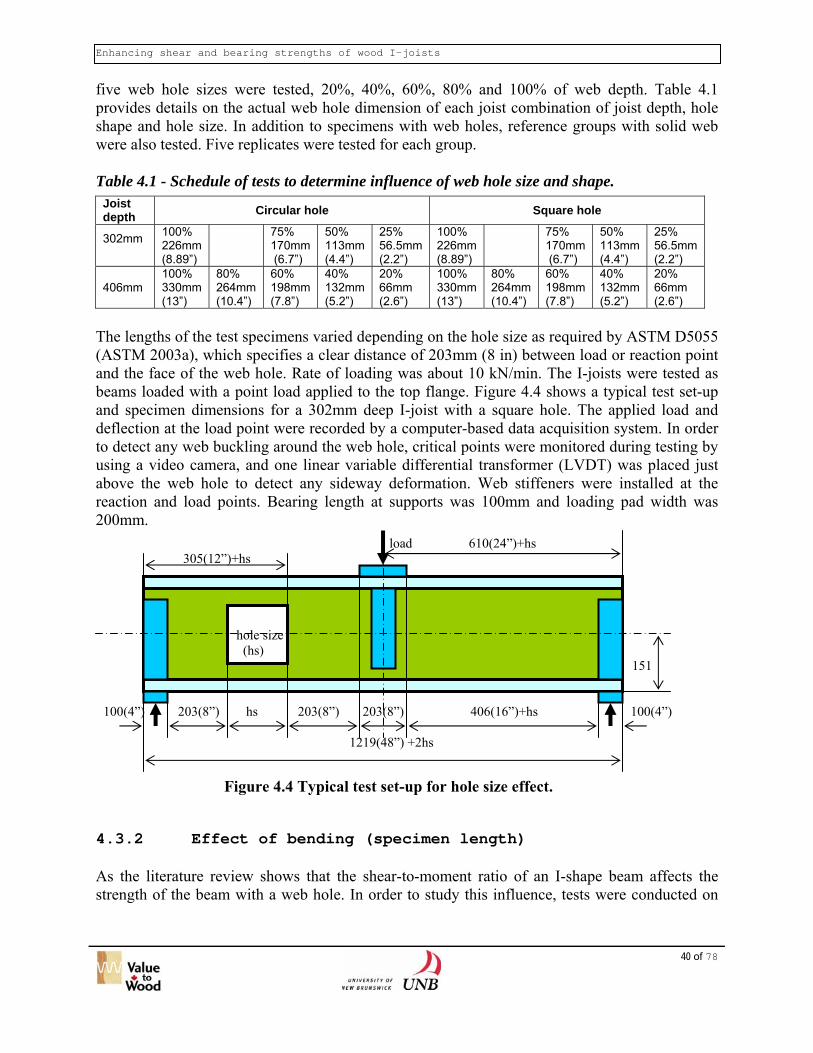
Enhancing shear and bearing strengths of wood I-joists
40 of 78
five web hole sizes were tested, 20%, 40%, 60%, 80% and 100% of web depth. Table 4.1 provides details on the actual web hole dimension of each joist combination of joist depth, hole shape and hole size. In addition to specimens with web holes, reference groups with solid web were also tested. Five replicates were tested for each group. Table 4.1 - Schedule of tests to determine influence of web hole size and shape.
Joist depth Circular hole Square hole
302mm
100% 226mm (8.89”)
75% 170mm (6.7”)
50% 113mm (4.4”)
25% 56.5mm (2.2”)
100% 226mm (8.89”)
75% 170mm (6.7”)
50% 113mm (4.4”)
25% 56.5mm (2.2”)
406mm 100% 330mm (13”)
80% 264mm (10.4”)
60% 198mm (7.8”)
40% 132mm (5.2”)
20% 66mm (2.6”)
100% 330mm (13”)
80% 264mm (10.4”)
60% 198mm (7.8”)
40% 132mm (5.2”)
20% 66mm (2.6”)
The lengths of the test specimens varied depending on the hole size as required by ASTM D5055 (ASTM 2003a), which specifies a clear distance of 203mm (8 in) between load or reaction point and the face of the web hole. Rate of loading was about 10 kN/min. The I-joists were tested as beams loaded with a point load applied to the top flange. Figure 4.4 shows a typical test set-up and specimen dimensions for a 302mm deep I-joist with a square hole. The applied load and deflection at the load point were recorded by a computer-based data acquisition system. In order to detect any web buckling around the web hole, critical points were monitored during testing by using a video camera, and one linear variable differential transformer (LVDT) was placed just above the web hole to detect any sideway deformation. Web stiffeners were installed at the reaction and load points. Bearing length at supports was 100mm and loading pad width was 200mm.
load 610(24”)+hs 305(12”)+hs hole size (hs) 151 100(4”) 203(8”) hs 203(8”) 203(8”) 406(16”)+hs 100(4”) 1219(48”) +2hs
Figure 4.4 Typical test set-up for hole size effect.
4.3.2 Effect of bending (specimen length) As the literature review shows that the shear-to-moment ratio of an I-shape beam affects the strength of the beam with a web hole. In order to study this influence, tests were conducted on
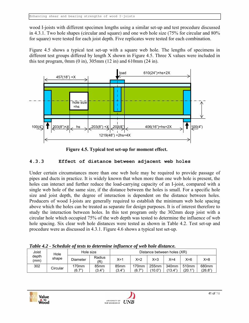
Enhancing shear and bearing strengths of wood I-joists
wood I-joists with different specimen lengths using a similar set-up and test procedure discussed in 4.3.1. Two hole shapes (circular and square) and one web hole size (75% for circular and 80% for square) were tested for each joist depth. Five replicates were tested for each combination. Figure 4.5 shows a typical test set-up with a square web hole. The lengths of specimens in different test groups differed by length X shown in Figure 4.5. Three X values were included in this test program, 0mm (0 in), 305mm (12 in) and 610mm (24 in).
load 610(24”)+hs+2X 457(18”) +X hole size =hs 100(4”) 203(8”)+X hs 203(8”) +X 203(8”) 406(16”)+hs+2X 100(4”) 1219(48”) +2hs+4X
F .
4.3.3 Eff Under certain circpipes and ducts in holes can interact single web hole ofsize and joist depProducers of woodabove which the hostudy the interacticircular hole whichhole spacing. Six cprocedure were as Table 4.2 - Schedu
Joist depth (mm)
Hole shape
302 Circular
igure 4.5. Typical test set-up for moment effect
41 of 78
ect of distance between adjacent web holes
umstances more than one web hole may be required to provide passage of practice. It is widely known that when more than one web hole is present, the and further reduce the load-carrying capacity of an I-joist, compared with a the same size, if the distance between the holes is small. For a specific hole th, the degree of interaction is dependent on the distance between holes. I-joists are generally required to establish the minimum web hole spacing les can be treated as separate for design purposes. It is of interest therefore to
on between holes. In this test program only the 302mm deep joist with a occupied 75% of the web depth was tested to determine the influence of web lear web hole distances were tested as shown in Table 4.2. Test set-up and
discussed in 4.3.1. Figure 4.6 shows a typical test set-up.
le of tests to determine influence of web hole distance. Hole size Distance between holes (XR)
Diameter Radius (R) X=1 X=2 X=3 X=4 X=6 X=8
170mm (6.7”)
85mm (3.4”)
85mm (3.4”)
170mm (6.7”)
255mm (10.0”)
340mm (13.4”)
510mm (20.1”)
680mm (26.8”)

Enhancing shear and bearing strengths of wood I-joists
42 of 78
305(12”) + (3+X)R load 508(24”) +(4+X)R 305(12”)+R 102(4”) 203 151
100(4”) 203(8”) 2R XR 2R 203(8”) 203(8”) 508(16”) +(4+X)R 100(4”)
1219(48”) + (8+2X)R
Figure 4.6 Typical test set-up with double circular hole. 4.4 Test Results and Discussion 4.4.1 Effect of web hole size and shape Table 4.3 shows the mean total failure load and angle of fracture line relative to the centre of the web hole (2) for each group. Figure 4.7 presents the normalized strength (strength of joist with a web hole over that of joist with a solid web) versus the ratio of web hole size over web depth. From Figure 4.7 it can be noted that for circular hole the percent reduction in strength is relatively independent of joist depth and the relationship between strength ratio and web hole size appears fairly linear. When the diameter of the circular web hole is equal to the web depth, the strength reduces to about 30% of the solid web strength. As was expected, square web hole has a bigger negative impact on strength than a circular hole of the same web hole ratio. The WIJMA document (1999) on web hole suggests that ‘a circular hole that can be inscribed in a rectangular hole are permitted to be assigned the same design value as the rectangular hole’. Clearly Figure 4.7 shows that it is conservative to use this approach for circular hole. With the developed test data it would be of interest to see if one can assign a circular web hole the same design value as a square hole which can be inscribed in that circle. The results are plotted in Figures 4.8 and 4.9 for 302mm (11-7/8 in) and 406mm (16 in) deep joists respectively. As can be noted from these figures the inscribed curve follows the square web hole relationship, indicating that this approach of assigning strength value is acceptable. The implication of this is that it may be sufficient for an I-joist manufacturer to test only, say, square web hole when qualifying a new product, and use this principle to assign design values for I-joists with a circular hole without the need to conduct another set of shear tests with a circular web hole.

Enhancing shear and bearing strengths of wood I-joists
0
0.1
0.2
0.3
0.4
0.5
0.6
0.7
0.8
0.9
1
0 0.2 0.4 0.6 0.8 1Hole size / Web depth
Stre
ngth
ratio Circular 16"
Square 16"Circular 12"Square 12"
. Table 4.3 - M
Sample No. Solid Shc-16-66 Shc-16-132 Shc-16-198 Shc-16-264 Shc-16-330 Solid Shs-16-66 Shs-16-132 Shs-16-198 Shs-16-264 Shs-16-330 Solid Shc-12-56 Shc-12-113 Shc-12-170 Shc-12-226 Solid Shs-12-56 Shs-12-113 Shs-12-170 Shs-12-226
Figure 4.7 Strength ratio versus ratio of hole size over web depth
43 of 78
easured failure load and failure angle for various web hole sizes. Joist depth (mm)
Hole shape
Hole size (mm)
Hole size / Web depth
Total failure load (kN)
Measured failure angle, θ (º)
406 0 0% 55.0 406 Circular 66 20% 53.76 323406 Circular 132 40% 42.79 324406 Circular 198 60% 30.99 321406 Circular 264 80% 22.00 321406 Circular 330 100% 15.50 318406 0 0% 55.02 406 Square 66 20% 50.99 315406 Square 132 40% 32.97 315406 Square 198 60% 19.58 315406 Square 264 80% 13.53 315406 Square 330 100% 9.82 315302 0 0% 46.62 302 Circular 56 25% 42.57 325302 Circular 113 50% 30.22 323302 Circular 170 75% 21.32 316302 Circular 226 100% 14.43 309302 0 0% 46.62 302 Square 56 25% 40.30 315302 Square 113 50% 24.04 315302 Square 170 75% 15.11 315302 Square 226 100% 12.44 315

Enhancing shear and bearing strengths of wood I-joists
12 in deep joists
0
0.1
0.2
0.3
0.4
0.5
0.6
0.7
0.8
0.9
1
0 0.2 0.4 0.6 0.8 1
Web hole size / Web depth
Stre
ngth
ratio
Square Circular hole inscribing a square
F
Figure 4.8 Comparison of strength ratio of square web hole and circular webhole inscribing a square - 12 inch deep joists.
16 in deep joists
0
0.1
0.2
0.3
0.4
0.5
0.6
0.7
0.8
0.9
1
0 0.1 0.2 0.3 0.4 0.5 0.6 0.7 0.8 0.9 1
Web hole size / Web depth
Stre
ngth
ratio
Square Circular hole inscribing a squareigure 4.9 Comparison of strength ratio of a square web hole and a circular webhole inscribing a square - 16 inch deep joists.44 of 78
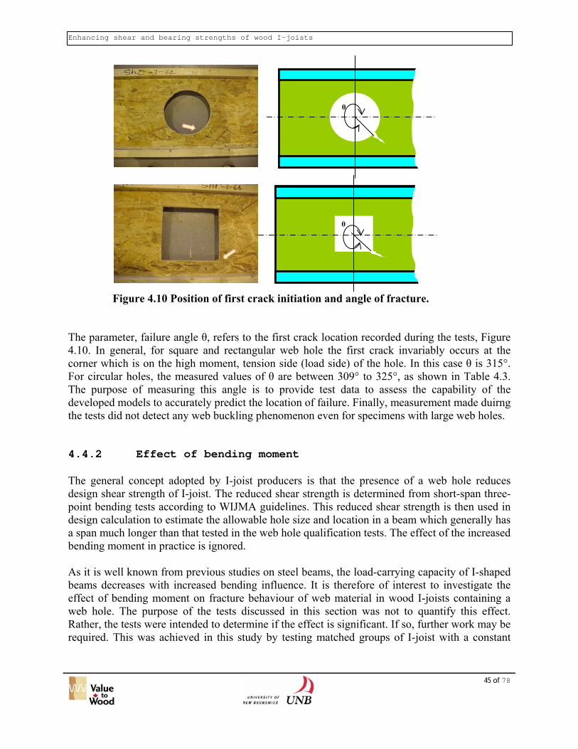
Enhancing shear and bearing strengths of wood I-joists
θ
θ
F
The param4.10. In gcorner whFor circulThe purpodevelopedthe tests di 4.4.2 The generdesign shepoint benddesign cala span mubending m As it is webeams deceffect of bweb hole.Rather, therequired. T
igure 4.10 Position of first crack initiation and angle of fracture.
45 of 78
eter, failure angle θ, refers to the first crack location recorded during the tests, Figure eneral, for square and rectangular web hole the first crack invariably occurs at the ich is on the high moment, tension side (load side) of the hole. In this case θ is 315°. ar holes, the measured values of θ are between 309° to 325°, as shown in Table 4.3. se of measuring this angle is to provide test data to assess the capability of the
models to accurately predict the location of failure. Finally, measurement made duirng d not detect any web buckling phenomenon even for specimens with large web holes.
Effect of bending moment
al concept adopted by I-joist producers is that the presence of a web hole reduces ar strength of I-joist. The reduced shear strength is determined from short-span three-ing tests according to WIJMA guidelines. This reduced shear strength is then used in
culation to estimate the allowable hole size and location in a beam which generally has ch longer than that tested in the web hole qualification tests. The effect of the increased oment in practice is ignored.
ll known from previous studies on steel beams, the load-carrying capacity of I-shaped reases with increased bending influence. It is therefore of interest to investigate the ending moment on fracture behaviour of web material in wood I-joists containing a
The purpose of the tests discussed in this section was not to quantify this effect. tests were intended to determine if the effect is significant. If so, further work may be his was achieved in this study by testing matched groups of I-joist with a constant

Enhancing shear and bearing strengths of wood I-joists
web hole size but with varied length such that the shear-to-moment ratio decreases with increasing specimen length. The test results are summarized in Table 4.4. Table 4.4 - Measured failure load and failure angle for various specimen length.
Sample No. Joist depth (mm)
Hole shape Length of I-joist (mm)
Hole size / web depth
Measured failure load (kN)
Measured critical
point θ (º) Shc-16-264-0 406 Circular 1747 80% 22.47 321 Shc-16-264-18 406 Circular 3576 80% 20.46 319 Shc-16-264-32 406 Circular 4998 80% Insufficient sample length Shs-16-264-0 406 Square 1747 80% 13.53 315 Shs-16-264-16 406 Square 3576 80% 12.33 315 Shs-16-264-32 406 Square 4998 80% Insufficient sample length Shc-12-170-0 302 Circular 1559 75% 21.32 316 Shc-12-170-12 302 Circular 2778 75% 20.14 321 Shc-12-170-24 302 Circular 3997 75% 18.55 320 Shs-12-170-0 302 Square 1559 75% 16.36 315 Shs-12-170-12 302 Square 2778 75% 14.95 315 Shs-12-170-24 302 Square 3997 75% 13.68 315
0.8
0.82
0.84
0.86
0.88
0.9
0.92
0.94
0.96
0.98
1
0 2 4 6 8 10 12 14
Span to depth ratio
Stre
ngth
ratio
rela
tive
to W
IJM
A te
st le
ngth
Circular 16 in Square 16 in Circular 12 in Square 12 in
F
It canmaximreduc15%
igure 4.11 Effect of span-to-depth ratio on load-carrying capacity of I-joist with aweb hole.
46 of 78
be noted from Figure 4.11 that the influence of bending moment can be significant. The um span-to-depth ratio tested in this study was just over 13. At this span-to-depth ratio the
tion in strength compared with the joist tested at the WIJMA recommended length is about for the particular location of web hole evaluated in this study. In practice, the span-to-depth

Enhancing shear and bearing strengths of wood I-joists
47 of 78
ratio is typically greater than 18. The limited tests conducted here indicate that further study is necessary to quantify the influence of shear-to-moment ratio on load-carrying capacity of wood I-joist with a web hole. 4.4.3 Interaction of web holes in I-joists containing two
web holes Tests were conducted on 302mm deep I-joist to provide a preliminary indication of the influence of distance between adjacent web holes on strength of I-joists. Only one joist depth and one circular hole size was tested. Table 4.5 and Figure 4.12 present the test results. The strength of I-joist with a single hole is also shown in Table 4.5 and Figure 4.12. It can be noted in Figure 4.12 that the strengths of all double-hole specimens are all smaller than the strength of single hole specimen (X=0). For small hole spacing the reduced strength is obviously due to the interaction between web holes. The strength reduction for large web hole spacings is due to the influence of bending as was discussed in 4.4.2. In view of this the test results have been adjusted using the data obtained in Section 4.4.2 for 302mm deep joist with a circular hole to remove the influence of bending. The adjusted results are also shown in Figure 4.12. A clear trend emerges after this adjustment. It appears that the minimum clear distance between holes beyond which no interaction occurs is 4 time the radius i.e. twice the web hole diameter. This finding agrees with the recommendation by Zhu (2003). Further work is necessary to identify critical distance for other joist depth and hole shape. Table 4.5 - Measured failure load for test specimens containing two web holes.
Sample No. Holes shape Holes size ratio
Length (mm)
Clear distance between two holes
(XR) (mm)
Measured failure load
(kN)
Shc-12-170-0 Single circular 75% 1559 0 21.32
Dhc-12-170-R Double circular 75% 2069 1R = 85 13.29
Dhc-12-170-2R Double circular 75% 2239 2R = 170 17.80
Dhc-12-170-3R Double circular 75% 2409 3R = 255 19.19
Dhc-12-170-4R Double circular 75% 2579 4R = 340 19.61
Dhc-12-170-6R Double circular 75% 2919 6R = 510 19.38
Dhc-12-170-8R Double circular 75% 3259 8R = 680 18.92

Enhancing shear and bearing strengths of wood I-joists
0
5
10
15
20
25
0 1 2 3 4 5 6 7 8 9
No. of half diameter between holes
Stre
ngth
(kN
)
Test results Adjusted results
Figure 4.12 Influence of clear web hole spacing on strength of I-joist.
Figure 4.13 shows the test set-up and Figure 4.14 presents a typical failure pattern of a test specimen with double holes after test. It is noted that the first crack occurs at the lower tension side of web hole that is subjected to a higher bending moment. Depending on the web hole spacing, the crack propagates to the other hole or to the flange-web boundary. .
Figure 4.13 Set-up for double-hole test
48 of 78

Enhancing shear and bearing strengths of wood I-joists
49 of 78
First crack
Figure 4.14 Failure pattern of double-hole specimen Dhc-12-
170-3R. 4.5 Material test program One of the objectives of this project was to develop models that can be used to predict the load-carrying capacity of a wood I-joist with one or multiple web holes. To evaluate the appropriateness of these models and the accuracy of their predictions, the test results presented above will be compared with model predictions. In order to provide material properties for input into the predictive models, a test program was conducted to determine the mechanical properties of OSB. Flange mechanical properties were obtained from the manufacturers and therefore no tests were conducted on the flange lumber. The OSB test specimens were obtained from the manufacturer of the I-joists that were tested in this project and discussed in Section 4.4. The test methods and results of the OSB material tests have been presented in Section 3.5.2. 4.6 Development of simplified calculation procedure for peak stress at the boundary of a web hole Although wood I-joist producers generally publish diagrams and charts that provide information on allowable web hole size and location for their products. The published information is generally based on results from empirical test programs specified by ASTM D5055 (ASTM 2003a) and WIJMA document (1999). Strictly the information is derived from specific test length and loading conditions, and its applicability to other condition needs to be evaluated as has been discussed in Section 4.4.2. Therefore it would be useful if a simplified design

Enhancing shear and bearing strengths of wood I-joists
50 of 78
procedure, based on mechanics principles, is developed that can be used by design engineers to estimate the load-carrying capacity of an I-joist with a web hole under any loading conditions and spans. As stated in 4.2.2, a simplified calculation procedure, based on the Vierendeel method, has been proposed by Wang and Cheng (1995) for predicting the load-carrying capacity of a wood I-joist with a rectangular web hole. This method could not account for stress concentration and is only applicable to rectangular web hole. The validity of the Wang and Cheng method is questionable since they proposed to use a criterion where two of the web hole corners reach the material strength. It seems that an alterative method is required that can account for stress concentration around web hole is more desirable. To that end the curved beam analysis method proposed by Chan and Redwood (1974) appears to deserve an evaluation to determine if it can be applied to wood-based I-joist. The limitation is that the curved beam method only applies to I-joist with a circular hole. The purpose of this section is to present a summary of the curved beam theory and provide a preliminary evaluation of the method. According to Chan and Redwood (1974), the parts of the beam near the hole can be treated as individual structural members, and analyzed using established structural mechanics methods. Consider the cross section shown in Figure 4.15. The resultant force Nф and moment Mф, acting at any cross section radiating from the centre of the web hole, can be calculated using simple flexure formula. Chan and Redwood (1974) showed that the normal stress due to bending at the edge of the web hole is given by Equation [3].
⎟⎟⎠
⎞⎜⎜⎝
⎛ −−
−+=
rZum
umrAM
b 1)(
φσ [3]
in which
dAyumr
yA
Zarea∫ +−+
−=)(
1
A = area of the inclined T-section defined by the angle, ф ; m – u = the distance from the hole edge to the centroid of the inclined tee-section as defined in Figure 4.16; y = coordinate measured from the centroid of the inclined T-section; r = web hole radius For the T-section shown in Figure 4.16, Z can be calculated using Equation [4].
( ) ( ) ( )[ ]rbuumrcbyumrcA
umrZ lnlnln1 1 −+−+−++−+−+
+−= ( ) [4]
At angle ф, the tangential stress at the edge of the hole can be calculated from Equation [5]
( )⎟⎟⎠
⎞⎜⎜⎝
⎛ −+=
Tt I
umMA
NK φφσ [5]
where K is the stress concentration factor and can be calculated using Equation [6]

Enhancing shear and bearing strengths of wood I-joists
51 of 78
( )( )
( )( )ZrumumrAumZrI
IumM
Zrum1
)umr(AM
K T
T
−−++−−
=−−
⎟⎠⎞
⎜⎝⎛ −
−−+
=φ
φ
[6]
in which IT = the moment of inertia of the inclined tee-section about its centroid.
Figure 4.16 Typical inclined T-section.
Hole center
C.G y1
u
c
m m-u
r b
a
V
N Nф
C.G Mф
The above calculation is repeated for various values of ф until a maximum value of σt is reached. Prediction of failure can be achieved by comparing the calculated maximum tangential stress with a failure criterion.
V/2
ф
Figure 4.15 Curved beam idealization.

Enhancing shear and bearing strengths of wood I-joists
52 of 78
4.7 Development of finite element models for
calculating stresses at boundary of web hole The SAP2000 finite element program is used in this study to carry out the computation of stresses for both circular and square web holes. The main features of the finite element analysis have been described in Section 3.4. Only more pertinent aspects of the FE analysis as related to wood I-joist with a web hole will be discussed below. 4.7.1 Finite element model for web with a circular hole Stress analysis around the web hole in an I-joist under applied loads is performed using SAP2000 commercial finite element program. A linear elastic two-dimensional plane stress approach is chosen for this analysis. Two-dimensional quadrilateral finite elements with three degrees-of-freedom (dof) at each node are chosen for the meshing scheme. In order to generate accurate stress values around the web hole, a large number of elements is placed around the boundary of the web-hole, with the meshing density gradually decreases as the distance from the hole increases. For circular web holes, the hole boundary is divided into 50 units about the centre of the circle, in order to make the web hole contour as close as possible to a circular shape. A typical web hole finite element mesh and stress contour is shown in Figure 4.17.
Figure 4.17 Finite element mesh (left) and stress contour (right) for 302mm depth I-joist
with 170mm diameter hole (stress in MPa). 4.7.2 Finite element model for web with a square hole The meshing scheme for a square hole is essentially similar to a circular hole. The only difference is that at a square hole corner, extremely fine meshes are constructed to achieve convergence in the peak stresses. A typical corner stress contour for a square hole is shown in Figure 4.18. One can note the high stresses at the corner compared with Figure 4.17.

Enhancing shear and bearing strengths of wood I-joists
53 of 78
Figure 4.18 Stress contour for 302mm depth I-joist with 170mm square hole (stress in MPa).
4.8 Application of FAM to predict fracture load Prediction of failure loads for wood I-joists with web holes is presented here. A fracture mechanics based approach in combination with finite element and curved beam theory is considered. Finite element method and curved beam theory are used to identify the location and calculate the magnitude of the critical tensile stress causing fracture in the tension zone at the hole boundary. Prediction of failure of loads based on calculated stresses and application of strength theories, such as Tsai-Wu, modified Tsai-Wu and Von Mises, was also attempted. However, the strength theories significantly under-estimated the failure loads and they are not presented in this report. The basis of the failure load prediction is the finite area method (FAM). A general introduction of the application of FAM, and the principal expressions describing application of the method to predict failure loads have already been presented in Section 3.6. Pertinent features of FAM has been presented above, however a detailed description of its application for predicting fracture load of I-joist with a web hole is given here. Once the magnitude of the peak tensile stress, σt, at hole boundary is determined through either finite element analysis or curved beam theory, it can be used to predict failure load through FAM. The application of FAM requires integration of stresses over a length xo, which is a function of the properties of the web material as is explained below, to estimate the resultant force applied over this length. A schematic illustration of stress distribution over xo is shown in Figure 4.19 for a circular hole, where the peak tensile stress occurs at an angle of θ = 35° to 45°. For square hole, the peak stress occurs at an angle of 45°, as illustrated in Figure 4.20.

Enhancing shear and bearing strengths of wood I-joists
σt
x0
. The predicted Equation [7]. I
where σt = calculated
Figure 4.19 Stress distribution over length x for a circular hole
0450
x0
σt
failn th
fP
pe
Figure 4.20 Stress distribution over length x for a square hole.
54 of 78
0
ure load of a joist with a web hole, Pfailure, can be calculated through the use of is equation the calculated peak stress is caused by an applied load, Papplied.
appliedtc
ailure PxfGEx
),(2
2 0
*0 σπ
= [7]
ak tensile stress at hole boundary using finite element or curved beam theory

Enhancing shear and bearing strengths of wood I-joists
55 of 78
2
*
02
t
c
fGE
xπ
= , length over which stress integration is performed
[ ])1(2),( 00 −= xxf tt σσ , for square hole
[ ])25(),( 00 πσσ −= xxf tt , for circular hole Other terms in Equation [7] are defined in section 3.6. 4.9 Verification of proposed strength prediction
methods Fracture loads based on FAM method were calculated for the two groups of I-joists tested in this study, namely 302mm and 406mm deep joists with 2x3 lumber flanges. The analysed joists had the same web holes as was discussed in Section 4.3. For circular web hole, the comparison of predicted and test fracture loads is presented in Figure 4.21 and 4.22 respectively for 302mm and 406mm deep joists. Also presented in Figures 4.21 and 4.22 are the predicted fracture loads using curved beam theory. It can be noted that for circular holes, the models grossly under-estimate the failure load especially for small web holes. The difference between predicted and test loads decreases as hole size increases. It was found that both curved beam analysis and finite element method provide similar peak load predictions. Hence it is not surprising that the fracture loads predicted by both models are similar as illustrated in Figures 4.21 and 4.22. In general the proposed FAM approach provides good predictions of the sensitivity of strength to changes in web hole size.

Enhancing shear and bearing strengths of wood I-joists
56 of 78
Circular web hole - 302mm deep joist
05
1015202530354045
0 0.2 0.4 0.6 0.8
Hole size / Web depth ratio
Failu
re lo
ad (k
N)
Test Curved beam Finite element
Figure 4.21 Comparison of predicted and test fracture load for 302mm depth I-joist with a circular web hole.
Circular web hole - 406mm deep joist
0
10
20
30
40
50
60
0 0.1 0.2 0.3 0.4 0.5 0.6 0.7
Hole size / Web depth ratio
Failu
re lo
ad (k
N)
Test Curved beam Finite element
Figure 4.22 Comparison of predicted and test fracture load for 406mm deep I-joist with a circular hole.
The comparison of predicted and test failure loads for I-joists with a square web hole is presented in Figures 4.23 and 4.24 for 302mm and 406mm deep joist respectively. It can be noted that, in contrast to the analyses for I-joists with a circular web hole, there is an excellent agreement between predicted and test failure loads and a tendency for the model to over-estimate the failure load. As in the case of circular web hole the agreement between predicted and test failure loads is better for larger web holes.

Enhancing shear and bearing strengths of wood I-joists
57 of 78
Square web hole - 302mm deep joist
0
10
20
30
40
50
60
0 0.1 0.2 0.3 0.4 0.5 0.6 0.7 0.8
Hole size / Web depth ratio
Failu
re lo
ad (k
N)
Test Finite element
Figure 4.23 Comparison of predicted and test fracture load for 302mm deep I-joist with a square hole.
Square web hole - 406mm deep joist
0
10
20
30
40
50
60
70
80
0 0.2 0.4 0.6 0.8
Hole size / web depth ratio
Failu
re lo
ad (k
N)
Test Finite element
Figure 4.24 Comparison of predicted and test fracture load for 406mm deep I-joist with a square hole.
As stated above the peak stresses predicted by curved beam analysis are generally in close agreement with the FE predictions. The minor difference between predictions from the two models can be attributed to the fact that FE discretization results in angular segments along the circular hole boundary. The presence of re-entrant corner, as a result of the straight line segmentation of the circular hole boundary results in increased stress concentration.

Enhancing shear and bearing strengths of wood I-joists
58 of 78
In addition to evaluating the capability of the model to predict failure load of I-joist with a single web hole, work was conducted to evaluate the capability of the finite element model in analyzing I-joist with two web holes. The same joist characteristics and dimensions tested in this project and described in Section 4.3.3 were analysed and the failure loads predicted using the finite element and FAM method. Only 302 mm deep I-joist with a 75% circular web hole was tested in this project and verification is therefore limited to this size of joist and web hole. A major difference between modeling approaches for single hole and double hole lies with the meshing scheme around the location of maximum stress. In the case of single hole, a finer mesh is generally provided between 35°- 45°orientation (with respect to vertical diameter of a hole). In the case of double hole, hole spacing has a significant influence on placing of the finer mesh. For close spacing, maximum stress tends to occur at an orientation greater than 45°. Therefore for double hole analysis the optimum location of finer mesh placement needs to be identified for each hole spacing. A comparison of the test and predicted failure loads is presented in Figure 4.25. From Figure 4.25 it is revealed that predicted failure loads are within the range of 68% - 75% of the test loads. This is similar to the single hole analysis results for circular hole. However the sensitivity of failure load to hole spacing is predicted well.
0
5
10
15
20
25
0 1 2 3 4
No. of clear hole radius between holes
Failu
re lo
ad (k
N)
Test FE prediction
Figure 4.25 Comparison of predicted and test failure load for 302mm deep I-joist with a
circular hole (75%). The stress analysis techniques presented above are based on linear-elastic material behaviour. They are found to be adequate for predicting first fracture load. For prediction of post-fracture load, non-linear inelastic analysis techniques are required. A more comprehensive material data base is required if more extensive verification and application of he models is desired. The curved beam analysis has been shown to provide conservative estimates of failure load. In general it provides a more accurate estimate of failure load for large web holes than small web

Enhancing shear and bearing strengths of wood I-joists
59 of 78
holes. In comparison with other possible design approaches such as Vierendeel method (Wang and Cheng 1995), the curved beam theory appears to provide better results. With some modifications it is possible to adopt it as a design tool. Based on the above comparisons, we can conclude that the proposed finite element based approach is suitable for use in performing sensitivity analysis to identify component properties that are important in governing the load-carrying capacities of wood I-joist with a web hole. The sensitivity analysis results are discussed in Section 4.9 below. 4.10 Sensitivity analysis As a demonstration of the application of the develop models, in this section the influence of material properties on predicted failure loads is examined. In particular the influence of moduli of elasticity (MOE) of both the flange and web material will be discussed. All analyses are applicable to joist sizes and characteristics that were tested in this project i.e. the flange was 2x3 lumber and web was 9.5mm thick OSB. 4.10.1 Influence of flange MOE on failure load Influence of flange MOE on fracture load in web of wood I-joist containing a circular web hole is presented in Figures 4.26 and 4.27 respectively for 302mm and 406mm deep joist. Corresponding influence for square web hole is shown in Figures 4.28 and 4.29. In each case the flange MOE is varied between 6000 MPa to 13000 MPa. The practical range for flange MOE is likely to be between 8500 MPa and 13000 MPa. It is noted that the increase in failure load is about 3% - 4% in each figure when MOE is increased from 8500 MPa to 13000 MPa. There is no clear difference in sensitivity between the two hole shapes studied. These results show that any change in flange MOE does not significantly affect web fracture around a web hole. Circular hole - 302mm deep joist
10
12
14
16
18
20
22
24
4000 6000 8000 10000 12000 14000
Flange MOE (MPa)
Failu
re lo
ad (k
N)
25% 50% 75%
Figure 4.26 Failure load vs. flange MOE for 302 mm deep joist with a circular web hole.

Enhancing shear and bearing strengths of wood I-joists
60 of 78
Circular hole - 406mm deep joist
10
15
20
25
30
5000 7000 9000 11000 13000 15000
Flange MOE (MPa)
Failu
re lo
ad (k
N)
40% 60% 80%
Figure 4.27 Failure load vs. flange MOE for 406 mm deep joist with a circular web hole.

Enhancing shear and bearing strengths of wood I-joists
61 of 78
Square web hole - 302mm deep joist
0
10
20
30
40
50
60
5000 7000 9000 11000 13000 15000
Flange MOE (MPa)
Failu
re lo
ad (k
N)
25% 50% 75%
Figure 4.28 Failure load vs. flange MOE for 302 mm deep joist with a square web hole.
Square hole - 406mm deep joist
01020304050607080
5000 7000 9000 11000 13000 15000
Flange MOE (MPa)
Failu
re lo
ad (k
N)
40% 60% 80%
Figure 4.29 Failure load vs. flange MOE for 406 mm deep joist with a square web hole.

Enhancing shear and bearing strengths of wood I-joists
62 of 78
4.10.2 Influence of web MOE on failure load of I-joist with a web hole
Influence of web MOE on fracture load in web of wood I-joist containing a circular web hole is presented in Figures 4.30 and 4.31 respectively for 302mm and 406mm deep joist. Corresponding influence for square web hole is shown in Figures 4.32 and 4.33. In each case the web MOE is varied between 3000 MPa to 10000 MPa. The practical range for web MOE is likely to be between 3000 MPa and 8000 MPa. It is noted that the increase in failure load is about 6% - 8% in each figure when MOE is increased from 3000 MPa to 8000 MPa. This sensitivity is higher than that for flange MOE. It should be mentioned that in these analyses the strength properties and fracture energy of the web material are maintained as constant for all web MOE values although web shear modulus is varied with web MOE. This assumption is unlikely to be true because strength and fracture properties are usually positively related to MOE for wood-based material. Therefore it can be concluded that the sensitivity of failure load to changes in web MOE is higher than the 6% - 8% range.

Enhancing shear and bearing strengths of wood I-joists
63 of 78
C irc u la r h o le - 3 0 2 m m d e e p jo is t
1 0
1 2
1 4
1 6
1 8
2 0
2 2
2 4
2 6
0 2 0 0 0 4 0 0 0 6 0 0 0 8 0 0 0 1 0 0 0 0 1 2 0 0 0
F la n g e M O E (M P a )
Failu
re lo
ad (k
N)
2 5 % 5 0 % 7 5 %
Figure 4.30 Failure load vs. web MOE for 302 mm deep joist with a circular web hole.
Circular hole - 406mm deep joist
10
15
20
25
30
35
0 2000 4000 6000 8000 10000 12000
Flange MOE (MPa)
Failu
re lo
ad (k
N)
40% 60% 80%
Figure 4.31 Failure load vs. web MOE for 406 mm deep joist with a circular web hole.

Enhancing shear and bearing strengths of wood I-joists
64 of 78
Square hole - 302mm deep
0
10
20
30
40
50
60
0 2000 4000 6000 8000 10000 12000
Flange MOE (MPa)
Failu
re lo
ad (k
N)
25% 50% 75%
Figure 4.32 Failure load vs. web MOE for 302 mm deep joist with a square web hole.
Square hole - 406mm deep joist
10
15
20
25
30
35
0 2000 4000 6000 8000 10000 12000
Flange MOE (MPa)
Failu
re lo
ad (k
N)
40% 60% 80%
Figure 4.33 Failure load vs. web MOE for 406 mm deep joist with a square web hole. 4.10.3 Influence of spacing between adjacent holes - double
hole analysis In Section 4.4.3 it was determined for one joist size and one hole size that the minimum clear distance between adjacent holes without stress interaction is 4 x hole radius. It is of interest to evaluate if the same conclusion also applies to other joist size. To this end stress analyses were performed to generate stress contours to compare the stress distributions for 302mm deep joist with a 75% circular web hole and 406mm deep joist with a 50% circular web hole. Selected results are summarized in Figure 4.34 and 4.35 respectively for 302mm and 406mm deep joists.

Enhancing shear and bearing strengths of wood I-joists
65 of 78
(a) 1 x R (b) 2 x R
(c) 4 x R (d) 4 x R (left hole)
(e) Single hole
Figure 4.34 Comparison of stress contour for 302mm deep joist with a 75% circular web hole.

Enhancing shear and bearing strengths of wood I-joists
66 of 78
(a) 1 x R (b) 2 x R
(c) 4 x R (d) 4 x R (left hole)
(e) Single hole
(a) 1 x R (b) 2 x R
(c) 4 x R (d) 4 x R (left hole)
(e) Single hole
Figure 4.35 Comparison of stress distribution of 406mm deep I-joist with a 50% circular web hole.

Enhancing shear and bearing strengths of wood I-joists
67 of 78
As expected, the peak stress decreases with increasing hole spacing for both depths. Note that the blue colour signifies the highest stress. The stress contour results in Figure 4.34 support the test results discussed in Section 4.4.2 that the minimum clear web hole spacing without significant stress interaction is about 4 times the hole radius for 302mm deep joist, since the stress distributions for single hole (Figure 4.34(e)) and double hole at 4 x radius spacing (Figure 4.34(d)) are almost identical. For the 406mm deep joist the predicted trend is similar to that for 302mm deep joist, as shown in Figure 4.35. In this case the stresses are generally lower than the 302mm deep joist because the hole size relative to web depth is smaller (50% vs 75%). Comparison of Figure 4.35(d) and (e) confirms that the critical spacing of 4 x hole radius also applies to this case. Further analyses are required to estimate the critical hole spacings for a broader range of hole sizes and shapes. 5 Conclusions Based on work performed in this project the following conclusions can be drawn. 1. Knife-through resistance of lumber flange is lower for load applied parallel to growth
rings than across. 2. An optimum web projection value exists for maximizing the resistance to knife-through
failure in flange. 3. For each hole shape, the relationship between percent reduction in failure load and the
ratio of web hole size to web depth appears to be independent of joist depth. 4. For the purpose of assigning load-carrying capacity, a square web hole can be treated the
same as a circular web hole which inscribes the square hole. 5. The effect of bending moment should be accounted for when evaluating the safe location
of a web hole. 6. For circular web holes, the critical clear distance between holes with negligible stress
interaction appears to be 4 times hole radius. 7. Fracture mechanics-based method provides accurate predictions of knife-through fracture
load and strength of I-joist with a square hole. 8. Simplified calculation procedure based on the curved beam theory provides conservative
estimates of failure load for I-joist with a circular web hole. 9. Effect of flange MOE on strength of I-joist with web hole is negligible within the
practical range.

Enhancing shear and bearing strengths of wood I-joists
68 of 78
6 Next Steps 1. Refine proposed optimum flange-web joint profile using modelling and testing, and
evaluate its validity for other flange geometry and properties. 2. Use developed model to derive substantiated recommendations for reducing testing
requirements for I-joists with web holes – spacing between holes, influence of flange quality, influence of web hole shape and size.
3. Develop a procedure to account for the influence of bending moment on strength of I-joist
with web holes, possibly using the curved beam theory as a basis.
7 References ASTM. 2003a. Standard specification for establishing and monitoring structural capacities of prefabricated wood I-joists. Designation D5055. American Society for Testing and Materials, West Conshohocken, PA. ASTM. 2003b. Standard Test Methods for Testing Structural Panels in Flexure. Designation D3043-00e1. American Society for Testing and Materials, West Conshohocken, PA. ASTM. 2003c. Standard Test Methods for Structural Panels in Tension. Designation D3500-90. American Society for Testing and Materials, West Conshohocken, PA. ASTM. 2003d. Standard Test Method for Shear Modulus of Wood-Based Structural Panels. Designation D3044-94. American Society for Testing and Materials, West Conshohocken, PA. Bodig, J. and Jayne, B.A. 1982. Mechanics of wood and wood composites. Van Nostrand Reinhold Company, New York, N.Y.
Bostrom, L. 1992. Method for determination of the softening behavior of wood and the applicability of a nonlinear fracture mechanics. Doctoral Thesis, Report TVBM-1012, Lund, Sweden. Bower, J.E. 1966a. Elastic Stresses Around Holes in Wide-Flange Beam. Journal of the Structural Division, ASCE, 92(2):85-101 Bower, J.E. 1966b. Experimental Stresses in Wide-Flange Beam with Holes. Journal of the Structural Division, ASCE, 92(5):167-186 Callister Jr., W. D. 2003. Material science and engineering an introduction. John Wiley and Sons, Inc. New York, N.Y.

Enhancing shear and bearing strengths of wood I-joists
69 of 78
Chan, P.W. and Redwood R.G. 1974. Stresses in Beams with Circular Eccentric Web Hole. Journal of the Structural Division, ASCE, 100(1):231-248. Chui, Y. H. and Smith, I. 1990. Influence of rotatory inertia, shear deformation and support condition on natural frequencies of wooden beams. Wood Science and Technology, 24, 233-245. Chung, K. F., Liu, T. C. H. and Ko, A.C.H. 2001. Investigation on Vierendeel mechanism in steel beams with circular web openings. Journal of Constructional Steel Research, 57:467-490. Chung, K.F., Liu, C.H. and Ko, A.C.H. 2003. Steel beams with large web openings of various shapes and sizes: an empirical design method using a generalized moment-shear interaction curve. Journal of Constructional Steel Research, 59:1177-1200. CSA. 2001. Standards on OSB and Waferboard. CSA O437 Series-93. Canadian Standards Association, Toronto. ON.
Davids, W. J., Landis E.N. and Vasic, S. 2003. Lattice models for the prediction of load-induced failure and damage in wood. Wood and Fiber Science, 35(1), 120-134. Erdogan, F. and Ratwani, M. 1971. Stress distribution in bonded joints. J. of Composite Materials, Vol. 5, 378-393. Forest Products Laboratory. 1999. Wood handbook – Wood as an engineering material. General Technical Report FPL-GTR-113. United States Department of Agriculture, Forest Service, Forest Products Laboratory, Madison, WI. Foschi, R. O., Yao, F. Z. 1993. Reliability analysis of wood I-joists. Can. J. Civ. Eng. 20, 564-573. Fergus, D.A. 1979. Effect of web voids and stiffeners on structural performance of composite I-beam, PhD Thesis. Purdue University, West Lafayette, IN. Gerald, H. V., Bostrom, L., Gustafsson, P. J., Raunta-Maunus, A., and Gowda, S. 1991. Application of fracture mechanics to timber structures: RILEM state-of-the-art report. Research Notes 1262, Technical Research Centre of Finland, Helsinki, Finland.
Hilson, B.O. and Rodd P.D. 1984. The Effect of Web Holes on the Behaviour and Ultimate Shearing Strength of Timber I-beams with Hardboard Webs. The Structural Engineer, 62B(4):69-78. Jauslin, C., Pellicane, P. J. and Gutkowski, R.M. 1995. Finite element analysis of wood joints. Journal of Materials in Civil Engineering, ASCE, 7(1):50-58.

Enhancing shear and bearing strengths of wood I-joists
70 of 78
Landelius, J. 1989. Finite area method. Report TVSM (in Swedish) -5043, Division of Structural Mechanics, Lund University, Lund, Sweden Liu, T.C.H. and Chung, K.F. 2003. Steel beams with large web openings of various shapes and sizes: finite element investigation. Journal of Constructional Steel Research, 59:1159-1176. Leichti, R. J., Falk, R. H. and Laufenberg, T. L. 1990. Prefabricated wood COMPOSITR I-BEAMS: a literature review, Wood and Fiber Science, 22(1): 62-79. Maley, J. D. 1987. Wood I-joists: a closer look. Proceedings of Structures Congress/87, Building Structures, American Society of Civil Engineers, New York, 221-235.
Milner, H. R. and Yeoh, E. 1991. Finite element analysis of glued timber finger joints. J. Struct. Engrg. ASCE, 117(3), 755-766. Morris, V., Gustafsson, P.J. and Serrano, E. (1996) “The shear strength of light-weight beams with and without a hole – A preliminary study”. Proceedings of Workshop on Mechanical Properties of Panel Products. Building Research Establishment, Watford, UK. SBA. 2002. Oriented strandboard and waferboard. Technical Bulletin, Structural Board Association, Toronto, ON. Schuler, A. and Adair, C. 2003. Engineered Wood Products – an Opportunity to “Grow the Pie”. Presentation at 37th International Wood Composites Materials Symposium, Washington State University, Pullman, WA. Serrano, E. 2000. On the mechanical behaviour of test specimens for wood-adhesive bonds. Report TVSM-3063. Lund University, Lund, Sweden. Sharp, D. J., Suddarth, S. K. and Beaulieu, C. 2000. Length effect in prefabricated wood I-joists. Forest Product Journal, 50(5): 29-42 Smith, I., Landis, E. and Gong, M. 2003. Fracture and fatigue in wood. 1st Edition, John Wiley and Sons, Chichester.
Tabarsa, T. 1999. Compression perpendicular-to-grain bebaviour of wood. Ph.D. Thesis, University of New Brunswick, Fredericton, NB. Wang, Z. M. 1990. Composite mechanics and composite structural mechanics. China Mechanical Industry Press (In Chinese). Wang, A. and Cheng, J.J.R. 1995. Shear behaviour of OSB wood composite I-beams with web opening. Report submitted to Canadian Forest Service, Department of Civil Engineering, University of Alberta, Edmonton, AL.

Enhancing shear and bearing strengths of wood I-joists
71 of 78
Wernersson, H. 1994. Fracture characterization of wood adhesive joints. Report TVSM-1006, Division of Structural Mechanics, Lund University, Lund, Sweden. WIJMA. 1999. Establishing shear capacities for prefabricated wood I-joists with hole. The Wood I-Joist Manufacturers Association. Zhu, E. C. 2003. Modelling the structural behaviour of OSB webbed timber I-beams. PhD Thesis, University of Brighton, Brighton, UK.

Enhancing shear and bearing strengths of wood I-joists
72 of 78
Appendix I - COMMERCIAL FLANGE-WEB JOINT PROFILE GEOMETRIES

Enhancing shear and bearing strengths of wood I-joists
73 of 78
WF-PROF1
Flange
Web
8.5 mm
6.3 mm
12.7 mm
9.5mm WF-PROF2
Flange
Web
9.5 mm
6.3 mm
12.7 mm
9.5mm

Enhancing shear and bearing strengths of wood I-joists
74 of 78
WF-PROF3
Flange
Web
7.2 mm
6.2 mm
13.2 mm
9.5mm
TWF-PROF
8.0 mm Flange
Web
7.2 mm
6.2 mm
13.5 mm
9.5mm

Enhancing shear and bearing strengths of wood I-joists
75 of 78