enhancement of power quality for distance relays on shunt ... · pdf filerelays on shunt-facts...
TRANSCRIPT

International Journal of Scientific & Engineering Research, Volume 5, Issue 5, May-2014 50 ISSN 2229-5518
IJSER © 2014 http://www.ijser.org
Enhancement of Power Quality for Distance Relays on Shunt-FACTS Compensated
Transmission Lines Dr.K.S.Srikanth, Dr.L.V.Narasimha Rao, K.Naresh, Ch.Punya Sekhar, V.Ramesh, P.Anjappa
Abstract—: In transmission lines we come across different types of faults. Some are severe which LG faults (short circuit faults) are. These faults cause a great disturbance to the consumers. So there is a need to clear these type of disturbances. The technique used to correct these disturbances is using distance relays. By using these distance relays we can clear the disturbances under severe faults that occur. But the major disadvantage associated with this distance relay is during sub synchronous condition the relay may misoperate. In order to overcome this disadvantage here in this paper the shunt FACTS devices (SVC & STATCOM) are introduced which are connected in long transmission lines. These Shunt FACTS devices stabilize the system voltage and current under fault conditions. Here In order to give gate pulses to the thyristors present in these shunt FACTS devices, we use neural networks. By using these neural networks we can maintain the relay current stable under fault condition through which we can eliminate the sub synchronous condition.
Index Terms— Distance protection relay, flexible ac transmission system (FACTS), DVR, series compensation, shunt compensationstaticSynchronouscompensators (STATCOM), staticvarcompensator (SVC) andNeuralNetwork
—————————— ——————————
1 INTRODUCTION ontinuous efforts are made to improve power system more efficient and reliable have seen increased use of FACTS devices in transmission systems. Most of the
FACTS devices are installed on existing transmission lines to enhance their capacity and performance [1]-[8]. Distance protection relays have been widely applied for protecting transmission lines [1]-[4]. Thus there is a very high probability that the transmission line where the FACTS device is being installed is protected by distance relay. This scenario brings up the question, “will the existing distance protection relay perform well with the new FACTS device in the transmission line?”. The objective of this paper is to find an answer to this question and also bring out important issues that could possibly affect the performance of the distance relay when protecting the shunt compensated line. The shunt FACTS devices (SVC and STATCOM) have fast response time, it is very important to consider the Reaction if the FACTS device to the fault when studying the effect on the distance relay measurements. This thesis considers elaborate models of the FACTS devices along with their control systems. Static var composters (SVC) are widely used in shunt compensation of transmission lines. With the acceptability of Gate Turn Off thyristors (GTO) among the utilities, static synchronous compensators (STATCOM) are also becoming popular [2].the location if shunt FACTS devices depends on the application for which it is installed. Shunt compensation FACTS devices are installed at the end points of the transmission line (buses) when used for applications, such as, improving system stability, improving HVDC link performance etc. however, for controlling the power flow or increasing the power transfer capability of very long transmission line mid-point of the lines is the best location for shunt connected FACTS devices. in this paper, the performance of distance relays on mid-point compensated line is studied. The neural networks controller is used to give triggering pulses to the power electronic based
thyristors in the shunt FACTS devices (SVC&STATCOM). By connecting neural networks in FACTS devices is to stabilizing the relay voltage relay current under fault condition in the long transmission lines and overcome the sub synchronous condition. The neural networks give fast time rate of pulses to the bidirectional thyristor switches in the shunt FACTS devices (SVC & STATCOM). SVC→ Static Var Compensator STATCOM→staticSynchronous Compensator
2 FACTS DEVICES Over the last decade FACTS devices have become popular and are tuning out to be a very effective solution for many power system transmission problems. FACTS devices can be broadly classified into 3 types,(a) shunt (b) series (c) composite series and shunt. FACTS devices are being presently employed for various applications, as follows: 1Increasing power transmission capacity of existing lines 2 Improving the steady state and dynamic stability limits. 3 Improving damping of different types of power oscillations. 4 Improving voltage stability. 5 Reducing the problem of sub-synchronous resonance
Fig 1: V-I characteristics of an SVC and STATCOM
C
IJSER
International Journal of Scientific & Engineering Research, Volume 5, Issue 5, May-2014 51 ISSN 2229-5518
IJSER © 2014 http://www.ijser.org
Shunt compensating FACTS devices are used for increasing the power transfer capability of a line by regulating the mid-point voltage of a transmission line around a set point, [1] and [2] give a good explanation on the principle of operation of FACTS devices and their controllers. Characteristics of SVC and STATCOM, which can potentially affect the relay perfor-mance, Rae discussed below
2.1Static Var Compensator (SVC) The SVC comprises the thyristor switched capacitor (TSC) and thyristor controlled reactor (TCR) connected in parallel to the connected in parallel to the compensation point of the system. With proper co-ordination of the capacitor switching and reac-tor control, the reactive output can be varied continuously between the capacitive and inductive ratings. Fig 1 Shows the voltage-current V-I characteristics of an SVC. Depending on the operating point of the SVC, its reactance varies (the slope of the line connecting of the operating point and origin in Fig 1 give the reactance value). Once the maximum capacitive out-put limit of the SVC is reached, the SVC operates as a fixed capacitor. At this condition, the maximum obtainable capaci-tive current decreases linearly and the generated reactive power decreases as a square of the system voltage [1]–[3]. Thus the minimum value of the capacitive reactance is when the SVC reaches its maximum capacitive rating limit. Any fur-ther reduction in voltage will only reduce the output rating retaining a constant reactance.
2.2 Static Synchronous Condenser (STATCOM) STATCOM provides a desired reactive power generation and absorption entirely by means of electronic processing of the voltage and current wave forms in a voltage source converter (VSC)Fig 2 shows the V-I Characteristics of STATCOM. The STATCOM is able to independently control its output current over the rated maximum capacitive or inductive range irre-spective of the amount of ac-system voltage. Unlike the SVC, the STATCOM can Provide full capacitive reactive current independent of the system voltage up to a system voltage of 0.15pu [1]-[3]. This would mean that the capacitive reactance of a STATCOM could go to a very low value. This would mean that the capacitive reactance of a STATCOM could go to a very low value.
Fig 2: V-I characteristics of a statcom
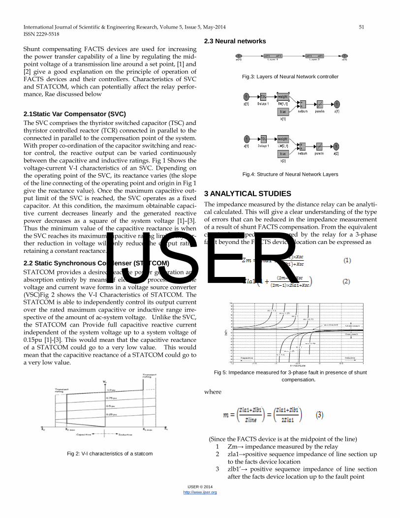
2.3 Neural networks
Fig.3: Layers of Neural Network controller
Fig.4: Structure of Neural Network Layers
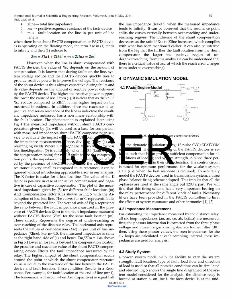
3 ANALYTICAL STUDIES The impedance measured by the distance relay can be analyti-cal calculated. This will give a clear understanding of the type of errors that can be reduced in the impedance measurement of a result of shunt FACTS compensation. From the equivalent circuit, the impedance measured by the relay for a 3-phase fault beyond the FACTS devices location can be expressed as
Fig 5: Impedance measured for 3-phase fault in presence of shunt compensation.
where
(Since the FACTS device is at the midpoint of the line)
1 Zm→ impedance measured by the relay 2 zla1→positive sequence impedance of line section up
to the facts device location 3 zlb1’→ positive sequence impedance of line section
after the facts device location up to the fault point
IJSER
International Journal of Scientific & Engineering Research, Volume 5, Issue 5, May-2014 52 ISSN 2229-5518
IJSER © 2014 http://www.ijser.org
4 zline→ total line impedance 5 xsc → positive sequence reactance of the facts device 6 m→ fault location on the line in per unit of line
length when there is no shunt FACTS compensation or FACTS devic-es is operating on the floating mode, the term Xsc in (1) tends to infinity and then (1) reduces to
However, when the line is shunt compensated with FACTS devices, the value of Xsc depends on the amount of compensation. It is known that during faults on the line, sys-tem voltage reduce and the FACTS devices quickly tries to provide reactive power to improve the voltage. The reactance of the shunt device is thus always capacitive during faults and its value depends on the amount of reactive power delivered by the FACTS device. The higher the reactive power support, the lower the value of Xsc. From (1), it is clear that as the value Xsc reduce compared to Zlb1’, it has higher impact on the measured impudence. In addition, since the reactance is ca-pacitive and series reactance of the line is inductive the result-ant impedance measured has a non linear relationship with the fault location. The phenomenon is explained later using Fig 4.The measured impedance without shunt FACTS com-pensator, given by (4), will be used as a base for comparison with measured impedances shunt FACTS compensator in ser-vice to evaluate the impact of shunt FACTS compensation on the impedance measurement. Hence, dividing (2) by (4) and rearranging yields Where K = Xsc/Zline = Xsc/Xline (for loss less line).Equation (5) is valid only when m>0.5 (fault beyond the compensation point) for m<0.5 fault before the compensa-tion point), the impedance measured by the relay is not affect-ed by the presence of FACTS device. Since the value of line resistance is very small as compared to its reactance, it can be ignored without introducing appreciable error in our analysis. The K factor is scalar for a loss less line. The value of the K factor is positive in case of inductive compensation and nega-tive in case of capacitive compensation. The plot of the meas-ured impedance given by (5) for different fault locations (m) And Compensation factor K is shown in Fig 5 with the As-sumption of loss less line. The curves for m>1 represents faults beyond the protected line. The vertical axis of Fig 4 represents the ratio between the fault impedance measured in the pres-ence of FACTS devices (Zm) to the fault impedance measured without FACTS device (Z’m) for the same fault location (m). These directly Represents the degree of under-reaching or over-reaching of the distance relay. The horizontal axis repre-sents the values of compensation (Xsc) in per unit of line im-pedance (Xline). For m<0.5, the measured impedance is same as the right hand side of (4) and hence Zm/Z’m = 1 as shown in Fig 5 However, for faults beyond the compensation location the presence and reactance value of the shunt FACTS compen-sating device Effects the fault impedance measured by the relay. The highest impact of the shunt compensation occurs around the point at which the shunt compensator reactance value is equal to the reactance of the line between the FACTS device and fault location. These condition Results in a Reso-nance. For example, for fault location at the end of line (m=1), The Resonance will occur when Xsc (capacitive) is equal half
the line impedance (K=-0.5) when the measured impedance tends to infinity. It can be observed that the resonance point splits the curves vertically between over-reaching and under-reaching regions. The influence of the shunt compensation decreases as the ratio if Xsc to Zline increases, which compiles with what has been mentioned earlier. It can also be inferred from the Fig that the further the fault location from the shunt compensator the larger the positive region of un-der/overreaching. from this analysis it can be understood that there is a critical value of xsc, at which the reach error changes from under to overreaching).
4 DYNAMIC SIMULATION MODEL
4.1 FActs Device Model
Fig.6: single line diagram system considered
For the dynamic simulation study, 12 pulse SVC/STATCOM is considered. The power rating of the FACTS devices is se-lected such that is can provide sufficient compensation for all conditions of loading and system strength. A slope three per-centage is employed in their characteristics. The control circuit is tuned for optimum performance for the weakest system state (i. e. when the best response is required). To accurately model the FACTS devices used in transmission system, a three phase balance firing scheme adopted. This implies that all the 3-phases are fired at the same angle but 1200 a part. We will find that this firing scheme has a very important bearing on the relay performance for different kinds of faults. Necessary filters have been provided in the FACTS controllers to limit the effects of system resonance and other harmonics [1], [2]
4.2 Impedance Measurement For estimating the impedance measured by the distance relay, all six loop impedances (an, an, cn, ab, bc&ca) are measured. first, the phasors information is extracted from the three phase voltage and current signals using discrete fourier filter (dft). then, using these phasor values, the seen impedances for the six loops are calculated at each sampling interval. these im-pedances are used for analysis.
4.3 Study System a power system model with the facility to vary the system strength, fault location, type of fault, load flow and direction of load is used so that all possible conditions can be simulated and studied. fig 5 shows the single line diagramed of the sys-tem model considered for the analysis. the distance relay is located at station a, on line i. the facts device is at the mid-
IJSER

International Journal of Scientific & Engineering Research, Volume 5, Issue 5, May-2014 53 ISSN 2229-5518
IJSER © 2014 http://www.ijser.org
point of the transmission line. the test cases have been selected so that all possible faults conditions are studied.
5 DYNAMIC SIMULATION STUDY
The power system and facts models discussed in the earlier section were built in the MATLAB software. Most of the simu-lation results obtained with both SVC and STATCOM are in arrangement with the analytical studies discussed in section III. However, there are additional insights obtained during the dynamic simulation study, which are mentioned in the follow-ing sections.
5.1 Facts response for unbalanced faults Since the FACTS devices (both SVC and STATCOM) were used for voltage control application, a balanced 3-phase firing was employed [2], FACTS devices control system acts on a DC voltage equivalent to the 3-phase system. Thus for unsymmet-rical faults in which faulty phases experience a serve under-voltage compared to the healthy phases, the FACTS devices would provide equal compensation for all the three phases. This means that healthy phases (s) voltages can increases due to this equal compensation. In addition, this in turn results in a reduced compensation, as the equivalent voltage will not be a true representation of the faulted phase. Thus for unsymmet-rical faults, the value of capacitive reactance of the FACTS de-vice depends on factors like, pre-fault load (load angle) and phases involved in the fault in addition to (also) applicable to symmetrical faults) the system strength and fault location. This effect can results in incorrect impedance measurements as will be shown in the simulation results presented in the next section. In addition, the over compensation of the healthy phases can result in an increased reactive current in healthy phases. This increases the possibility of incorrect phase sec-tion, particularly if the relay installed uses current based phase section. The result obtained from testing a commercial relay using RTDS, conform this point and are reported in section VII of this thesis. But we are not using the RTDS software, so we cannot observe these type test results.
5.2 Characteristics of SVC & STATCOM
The difference in the V-I characteristics SVC and STATCOM in the capacitive region (Fig1&2) has an influence on the imped-ance measured during faults. In case of an SVC, the shunt ca-pacitive reactance decreases as its reactive power compensa-tion (MVAR) increases. Once the capacitive compensation lim-it is reached, the SVC behaves as constant capacitive reactance during which its shunt reactance is minimum and a further reduction in voltage leads to a corresponding reduction in reactive power compensation. In the case of a STATCOM, it has the capability to provide full capacitive output current at any system voltage down to 0.15pu, in contract to SVC which can supply only diminishing output current with decreasing system voltage as determined by its minimum capacitive reac-tance. this means that once the STATCOM reaches its maxi-mum capacitive current while the voltage continuous fall in down, the STATCOM shunt capacitive reactance will continue
to reduce maintain the output current constant as its maxi-mum limit. their behavior.
5.3 RESONANCE CONDITION FOR THREE PHASES FAULTS For three phase faults there us a particular location of the fault at which the measured impedance tends to infinity. When a three phase fault occurs are around this location, It results in a highly modulated fault current and voltage waveform. As a result, the fault impedance can take a very long time to con-verge. This can even lead other relays in the system to see this as a power swing. Fig 6 shows the fault voltage and current of one such condition obtained during the simulation tests for STACOM. Fig 7 shows the voltage at the FACTS location (mid-point of the line) for the same case. At the STACOM ex-hibits a much lower maximum capacitive reactance compared to that of an SVC such resonance problem is more likely to occurs in case of STATCOM than SVC for faults within the protected line. This depends on the combination of the length of the line, the minimum capacitive reactance of the FACTS device, and the fault location.
6 SIMULATION RESULT
Fig.7: MATLAB circuit for SVC (FACTS device) connected long transmission line
Fig.8: Operational circuit of relay in the Long transmission line.
IJSER

International Journal of Scientific & Engineering Research, Volume 5, Issue 5, May-2014 54 ISSN 2229-5518
IJSER © 2014 http://www.ijser.org
Fig.9: MATLAB circuit for the FACTS (STATCOM) Long Transmission line.
Fig.10: Impedance plane Diagram for Long transmission line under 3-phase Fault.
Fig.11: Fault current and voltage seen by the relay for a fault close to the resonance location.
Fig.12: Fault current and voltage seen by the relay for a fault close to the resonance location under the connection of FACTS devices (Neural networks controller).
Fig.13: Stabilized 3-phase RMS voltage at the midpoint line (FACTS device).
6.1. Effect on Operating Time The transient response of the FACTS controllers during faults causes its shunt reactance to transiently vary from the pre-fault value to the steady state value. This phenomenon causes
the impedance locus seen by a relay to longer time to converge to the steady state value. Most of the distance relays use con-vergence algorithm to determine the zone of fault (e.g, the fault impedance measured does not change more than 5% for few conceptive samples) and these moving locus of the im-pedance can delay the operating time of the relay considera-bly.
7 DYNAMIC SIMULATION RESULTS The results of the dynamic simulation are shown in fig 11 & fig 12. The fig 11 shows the Fault current and voltage seen by the relay for a fault close to the resonance location and the fig 12 shows the Fault current And voltage seen by the relay for a fault close to the resonance location under the connection of FACTS devices (Neural Networks).From the fig 10 shows the impedance plane Diagram for Long transmission line under 3-phase Fault. Generally the entry with in brackets in some cells shows the load angle and direction are flow for which the maximum error was noted. Where there is no mentioned of load or direction, the error was same regardless of the load flow and direction. The above things are shown diagrammati-cally in fig 14.
7.1 Fault Type and Load The amount of pre-fault load has an influence on the error only for unbalanced fault. This is due to the balanced response of FACTS device even for unbalanced faults. A minimum amount of error variation with respective pre –fault loading was observed for the phase faults. In case SVC the maximum error was observed for 1-phase to ground Faults. Whereas STATCOM, Highest error was observed for 3-phase faults
7.2 Fault Location The amount error was observed to be higher for faults at the end of the line. This is in accordance with the analytical re-sults, that higher errors are expected when the ratio of shunt compensating reactance to the line is lower. In contrast, there are no effects of FACTS on the measured impedance for fault location up to the FACTS point.
7.3 System strength The effect on the impedance measurement was found to be higher for a weak system. Fault voltages are lower in weak system as compared to a strong one. In case of STATCOM, the over-reaching conditions occur only when the system is weak. On the other hand, their was no case of over-reaching noted for SVC. However, over-reaching might be possible for very long transmission lines or faults in the adjacent lines. Fig 10 shows some of the test results plotted on an impedance plane. This Fig 10 shows the direction of the load flow in load angles. The results are obtained by using the MATLAB software. In the legend:The first two digits numeral represents the load angle.The next two letters (A&B) represent the direction of load flow, “AB” means on the protected line is form section A to section B. “BA” means load is from section B to section A. The last set of letters “s” or “ns” denotes if the line is compen-sated or not respectively.The letters “XX” means that it repre-sents all load flow and load direction.The relay characteristics
IJSER

International Journal of Scientific & Engineering Research, Volume 5, Issue 5, May-2014 55 ISSN 2229-5518
IJSER © 2014 http://www.ijser.org
is shown as a circle (mho characteristics), set to cover 100% of the protected line, which is an effective way of representing the line. Faults are applied at 25%, 50%, 75% and 100% of the transmission line. The marking on the line represent the measured impedance at each of the four fault locations. Fig 10 shows the result obtained for a weak system with SVC under 1-phase to ground faults. It can be clearly seen that the amount of load and direction of load flow has a greater influence of the measured impedance. For a strong system, the result ob-tained had similar pattern. Fig (10) Show the results for a weak system with STATCOM for AN and ABC faults respec-tively. As mentioned earlier, the chances of the compensating reactance becoming lesser than the critical value are more in case of STATCOM.
8 INFERENCES From the above studies, the effect of mid-point shunt FACTS compensation on distance really can be inferred as follows: In long transmission lines we came across different types of faults. The line ground faults are much severe to the consum-er. Under fault situation the consumer face dangerous condi-tions. i.e consumers systems are shutting down completely or collapsed. Then these faults cause great disturbances to the consumers. So there is a need to clear these type of disturb-ances. One such technique to correct these disturbances is us-ing distance relays. The distance relays consists of circuit breaker, AND logical operator, current measurements and Trip circuit. The current measurements are used to measure the transmission line current under fault condition. This measured current flows through the AND logical operator. By using these distance relays we can clear the disturbances un-der severe faults that occur. But the major disadvantage asso-ciated with this distance relay is during sub synchronous con-dition the relay may mis operate. i.e in sub synchronous con-dition, highly modulated voltages and currents are drawn. At this condition the fault impedance tends to infinity. Then realy mis operating condition obtained (do not locate position of the fault). From the Fig 11 shows the Fault current and voltage seen by the relay for a fault close to the resonance location. This AND logical operator gives signal to the trip circuit. The AND logical operator is used to control all the 3-phases if fault occur in any phase. The trip circuit gives the trip signal to the circuit breaker. i.e in the long transmission line the distance relays are used to isolate the fault section from the healthy section. Fault Impedance=Infinity[Fault current zero condi-tion]In order to overcome this disadvantage here in this thesis we are shunt FACTS devices (SVC & STATCOM) which are connected in long transmission lines. These shunt FACTS de-vices (SVC&STATCOM) stabilizes the system voltage and cur-rent under fault conditionsHere In order to give gate pulses to the thyristors present in these shunt FACTS devices, we use neural networks. By using these neural networks we can maintain the relay current stable under fault condition through which we can eliminate the sub synchronous condi-tion. From the Fig 12 shows the Fault current and voltage seen by the relay for a fault close to the resonance location under the connection of FACTS devices(Neural networks controller). The comparison of Fig 11 and Fig 12, the relay current not
tends to zero in the presence of shunt FACTS devices under the connection of neural networks
Fig 14: Legend used for representing the measured impedance for different system conditions in the impedance plane.
Then the relay cannot mis operate and the distance relay lo-cates the fault position under reducing sub synchronous con-dition.
9 CONCLUSION To overcome the sub synchronous condition in long transmis-sion lines, here we used shunt FACTS devices SVC (static var compensator) and STATCOM (Static synchronous compensa-tor). By using the neural networks based shunt FACTS devic-es; we can stabilize the system’s voltage and current as well as relay’s voltage and current under fault conditions. The results can be obtained using simulink and are verified successfully.
REFERENCES [1] “Performance of Distance Relays on Shunt—FACTS Compensated Transmission Lines” Tarlochan Singh Sidhu, Fellow, IEEE, Rajiv K. Varma, Member, IEEE, Pradeep Kumar Gangadharan, Student Member, IEEE, Fadhel Abbas Albasri, Student Member, IEEE, and German Rosas Ortiz, Student Member, IEEE TRANSACTIONS ON POWER DELIVERY, VOL. 20, NO. 3, JULY 2005 [2] N.G.HINGORONI and L.GYUGYI, understanding FACTS: concepts & technology of Flexible AC transmission systems Newyork: wiley, NOV. 1993. [3] R.K.VARMA and R.M.MADHUR, thyristor-based FACTS controller for electrical transmission system: wiley/IEEE press, FEB.2002. [4] L.GYUGYI, “converter-based FACTS controllers,” in Inst. ELEECT.ENG.colloq.flexible AC transmission system-the FACTS, NOV.23, 1998. [5] P.MOORE and P.ASHMOLE, “flexible AC transmission systems,” in inst ELECT.ENG.power engineering.J.vol.9, no.6, pp.282-286, DEC.1995. [6] “flexible AC transmission systems.II.methods of transmission line compensation,” proc. Inst. Elect.Engg.Power Engg.J.,VOL.10 no.6, pp.273-278, DEC.1996. [7] “flexible AC transmission systems.III, conventional FACTS controllers,” proc. Inst. Elect. Engg. Power engg.J., VOL.11,no.4 pp.177-183,AUG.1997. [8] ”flexible AC transmission systems, IV. Advanced FACTS
XX_XX_ns 20_AB_s 20_BA_s 40_AB_s 40_BA_s
60_AB_s 60_BA_s
IJSER

International Journal of Scientific & Engineering Research, Volume 5, Issue 5, May-2014 56 ISSN 2229-5518
IJSER © 2014 http://www.ijser.org
controllers,” proc.inst.Elect.Engg. power engg.j.vol.12, no.2,pp.95-100,APR.1998. [9] IEEE guide for a detailed functional specification and application of static VAR compensators, IEEE std.1031- 1991, MAR.26,1992. [10] Network protection and automation guide, 3rd ed.. alstom,2002. [11] D.novosel, A.phadke, M.M.SAHA, and S.lindahl,” problems and solutions for micro processor protection of series compensated lines,” proc.inst. Elct.Engg. conf.devolepment powersystem protection, pp.18-23, MAR.25-27,1997.
IJSER