enhanced teletext specification etsi · 2000-02-02 · 9.8 broadcast service data packets..... 48...
TRANSCRIPT

EUROPEAN ETS 300 706
TELECOMMUNICATION May 1997
STANDARD
Source: EBU/CENELEC/ETSI JTC Reference: DE/JTC-TTEXT-EACEM
ICS: 33.020
Key words: Broadcasting, data, transmission, Teletext, TV
European Broadcasting Union Union Européenne de Radio-Télévision
Enhanced Teletext specification
ETSI
European Telecommunications Standards Institute
ETSI Secretariat
Postal address: F-06921 Sophia Antipolis CEDEX - FRANCEOffice address: 650 Route des Lucioles - Sophia Antipolis - Valbonne - FRANCEX.400: c=fr, a=atlas, p=etsi, s=secretariat - Internet: [email protected]
Tel.: +33 4 92 94 42 00 - Fax: +33 4 93 65 47 16
Copyright Notification: No part may be reproduced except as authorized by written permission. The copyright and theforegoing restriction extend to reproduction in all media.
© European Telecommunications Standards Institute 1997.© European Broadcasting Union 1997. All rights reserved.

Page 2ETS 300 706: May 1997
Whilst every care has been taken in the preparation and publication of this document, errors in content,typographical or otherwise, may occur. If you have comments concerning its accuracy, please write to"ETSI Editing and Committee Support Dept." at the address shown on the title page.

Page 3ETS 300 706: May 1997
Contents
Foreword .......................................................................................................................................................9
1 Scope ................................................................................................................................................11
2 Normative references........................................................................................................................12
3 Definitions, symbols and abbreviations .............................................................................................123.1 Definitions ..........................................................................................................................123.2 Symbols .............................................................................................................................133.3 Abbreviations .....................................................................................................................13
4 TV lines usable as data lines.............................................................................................................144.1 When multiplexed with a composite video signal ..............................................................144.2 When not multiplexed with a composite video signal ........................................................14
5 Signalling characteristics...................................................................................................................155.1 Signalling method ..............................................................................................................155.2 Data Signal Levels .............................................................................................................155.3 Bit Rate ..............................................................................................................................155.4 Spectrum of data pulses ....................................................................................................15
6 Teletext packet identification.............................................................................................................156.1 Clock run-in........................................................................................................................156.2 Framing code.....................................................................................................................166.3 Timing reference................................................................................................................16
7 Organization of Teletext data elements ............................................................................................177.1 Elements of a Teletext packet ...........................................................................................17
7.1.1 Synchronization sequence ............................................................................177.1.2 Packet address..............................................................................................177.1.3 Data bytes .....................................................................................................177.1.4 Packet types..................................................................................................17
7.2 Elements of a page............................................................................................................187.2.1 Definition of a page .......................................................................................187.2.2 Page header packet ......................................................................................197.2.3 The body of a page .......................................................................................19
7.3 Elements of a magazine ....................................................................................................197.4 Elements of the service ..................................................................................................... 20
8 Byte coding and error protection .......................................................................................................218.1 Odd parity ..........................................................................................................................218.2 Hamming 8/4 .....................................................................................................................218.3 Hamming 24/18 .................................................................................................................22
9 Coding of data packets .....................................................................................................................239.1 Overview of packet types...................................................................................................239.2 Reserved bits .....................................................................................................................269.3 Directly displayable data packets.......................................................................................26
9.3.1 Page header..................................................................................................269.3.1.1 Page number .......................................................................279.3.1.2 Page sub-code.....................................................................279.3.1.3 Control bits...........................................................................279.3.1.4 Data bytes............................................................................28
9.3.2 Packets X/1 to X/25.......................................................................................299.4 Page enhancement data packets ......................................................................................29
9.4.1 Packet X/26 ...................................................................................................30

Page 4ETS 300 706: May 1997
9.4.2 Packet X/28/0 Format 1................................................................................ 309.4.2.1 Page Function and Page Coding ........................................ 309.4.2.2 Coding for basic Level 1 Teletext pages............................. 319.4.2.3 Coding for data broadcasting pages ................................... 349.4.2.4 Coding for other types of page............................................ 34
9.4.3 Packet X/28/0 - Format 2.............................................................................. 349.4.4 Packet X/28/1 ............................................................................................... 359.4.5 Packet X/28/2 ............................................................................................... 369.4.6 Packet X/28/3 ............................................................................................... 369.4.7 Packet X/28/4 ............................................................................................... 37
9.5 Magazine-Related Page Enhancement Data Packets ...................................................... 389.5.1 Packet M/29/0............................................................................................... 389.5.2 Packet M/29/1............................................................................................... 399.5.3 Packet M/29/4............................................................................................... 40
9.6 Packets for Page Linking .................................................................................................. 419.6.1 Packets X/27/0 to X/27/3 for Editorial Linking .............................................. 419.6.2 Packets X/27/4 and X/27/5 - Format 1 - for compositional linking in
presentation enhancement applications ....................................................... 439.6.3 Packets X/27/4 to X/27/7 - Format 2 - for compositional linking in data
broadcasting applications ............................................................................. 469.7 General Coding of packets 30 and 31............................................................................... 479.8 Broadcast Service Data Packets....................................................................................... 48
9.8.1 Packet 8/30 Format 1 ................................................................................... 489.8.2 Packet 8/30 Format 2 ................................................................................... 50
10 System Components for Presentation.............................................................................................. 5110.1 Basic Teletext - Presentation Levels 1 and 1.5................................................................. 5110.2 Enhanced Teletext - Presentation Levels 2.5 and 3.5 ...................................................... 5210.3 Page Specific Enhancement Data .................................................................................... 52
10.3.1 Enhancements via X/26/0 - 15...................................................................... 5310.3.2 Enhancements via X/28/0 Format 1 ............................................................. 5310.3.3 Enhancements via X/28/1............................................................................. 5310.3.4 Enhancements via X/28/4............................................................................. 53
10.4 Magazine Specific Enhancement Data ............................................................................. 5310.5 Public Enhancement Data................................................................................................. 54
10.5.1 Object Definition Pages ................................................................................ 5410.5.1.1 Page Format ....................................................................... 5410.5.1.2 Pointer Table....................................................................... 5410.5.1.3 Object Definition Area ......................................................... 5510.5.1.4 Page Number Identification................................................. 56
10.5.2 DRCS Downloading Pages........................................................................... 5610.5.2.1 Page Format ....................................................................... 5610.5.2.2 Page Number Identification................................................. 56
10.6 Magazine Organization Table ........................................................................................... 5610.6.1 Page Format ................................................................................................. 5610.6.2 Object Page Association............................................................................... 5810.6.3 DRCS Page Association............................................................................... 5810.6.4 Object Links.................................................................................................. 58
10.6.4.1 Default Objection Invocation ............................................... 5910.6.5 DRCS Links .................................................................................................. 6010.6.6 Number of Enhancement Pages .................................................................. 61
10.7 Links between Enhanced System Components................................................................ 6210.7.1 Linking to Object and DRCS Pages via the MOT......................................... 6210.7.2 Linking to Object and DRCS Pages via Packets X/27/4 and X/27/5 ............ 63
11 System Components for Navigation ................................................................................................. 6411.1 Navigation via FLOF.......................................................................................................... 64
11.1.1 Principles ...................................................................................................... 6411.1.2 Additional components ................................................................................. 64
11.2 Navigation via TOP ........................................................................................................... 6511.2.1 Principles ...................................................................................................... 6511.2.2 Additional components ................................................................................. 66
11.3 Magazine Inventory Page.................................................................................................. 67

Page 5ETS 300 706: May 1997
11.3.1 Principles.......................................................................................................6711.3.2 Format of the Magazine Inventory Page .......................................................6711.3.3 Page Function Coding...................................................................................6811.3.4 Sub-page range.............................................................................................71
12 Presentation Levels...........................................................................................................................7112.1 Display Components..........................................................................................................7212.2 Spacing attributes ..............................................................................................................7612.3 Non-spacing attributes and additional characters..............................................................80
12.3.1 Use of Packets X/26......................................................................................8012.3.2 Active Position...............................................................................................8212.3.3 Row Address triplets .....................................................................................8212.3.4 Column Address triplets ................................................................................89
12.4 Colour Map ........................................................................................................................9612.5 Side Panels........................................................................................................................96
12.5.1 Panel position................................................................................................9712.5.2 Panel size ......................................................................................................9712.5.3 Data transmission and addressing................................................................9712.5.4 Display rules ..................................................................................................98
13 Objects ..............................................................................................................................................9813.1 Object definitions ...............................................................................................................9813.2 Display priority order ..........................................................................................................9913.3 Active Objects ....................................................................................................................9913.4 Adaptive Objects................................................................................................................9913.5 Passive Objects ...............................................................................................................10013.6 Object invocation .............................................................................................................10013.7 Screen position of Object elements .................................................................................10113.8 Default Objects ................................................................................................................10113.9 Object example................................................................................................................102
14 Dynamically Re-definable Characters .............................................................................................10314.1 Downloading pages .........................................................................................................10314.2 DRCS Character Modes ..................................................................................................104
14.2.1 Mode 0 - 12x10x1........................................................................................10414.2.2 Mode 1 - 12x10x2........................................................................................10414.2.3 Mode 2 - 12x10x4........................................................................................10414.2.4 Mode 3 - 6x5x4............................................................................................105
14.3 Flashing DRCS ................................................................................................................10514.3.1 Mode 0 ........................................................................................................10514.3.2 Modes 1, 2 and 3.........................................................................................105
14.4 DRCS availability .............................................................................................................10514.4.1 Level 2.5......................................................................................................10514.4.2 Level 3.5......................................................................................................106
15 Character sets and their designation...............................................................................................10815.1 Overview of designation requirements ............................................................................10815.2 Designation of default G0 and G2 sets and national option sub-sets..............................10815.3 Second G0 Set Designation and National Option Set Selection......................................11015.4 Modified G0 and G2 Character Set Designation .............................................................11215.5 Spacing attributes ............................................................................................................11315.6 Alphanumeric Character Sets..........................................................................................113
15.6.1 Latin G0 Set ................................................................................................11415.6.2 Latin National Option Sub-Sets ...................................................................11515.6.3 Latin G2 Set ................................................................................................11615.6.4 Cyrillic G0 Set - Option 1 - Serbian/Croatian...............................................11715.6.5 Cyrillic G0 Set - Option 2 - Russian/Bulgarian.............................................11815.6.6 Cyrillic G0 Set - Option 3 - Ukrainian ..........................................................11915.6.7 Cyrillic G2 Set..............................................................................................12015.6.8 Greek G0 Set ..............................................................................................12115.6.9 Greek G2 Set ..............................................................................................12215.6.10 Arabic G0 Set ..............................................................................................12315.6.11 Arabic G2 Set ..............................................................................................124

Page 6ETS 300 706: May 1997
15.6.12 Hebrew G0 Set ........................................................................................... 12515.7 Graphics Character Sets................................................................................................. 126
15.7.1 G1 Block Mosaics Set................................................................................. 12615.7.2 G3 Smooth Mosaics and Line Drawing Set ................................................ 127
Annex A (normative): Encoding Rules................................................................................................ 128
A.1 Page numbering ............................................................................................................................. 128
A.2 Use of control bits C4 (Erase Page) and C8 (Update Indicator)..................................................... 129
A.3 Backwards compatibility in X/26 addressing................................................................................... 129
A.4 Addressing order for enhancement triplets..................................................................................... 129
A.5 Rules for row and screen colours ................................................................................................... 130
A.6 Object definition pages ................................................................................................................... 130
A.7 Rules for the overlapping and interleaving of objects ..................................................................... 130A.7.1 Overlapping rules ............................................................................................................ 130A.7.2 Interleaving rules ............................................................................................................. 131
A.8 Number of objects per page ........................................................................................................... 131
A.9 Coding of packets 8/30, Formats 1 and 2....................................................................................... 132
Annex B (normative): Transmission Rules ......................................................................................... 133
B.1 Transmission of basic Teletext pages with a page erasure interval ............................................... 133
B.2 Transmission order of packets with Y = 26, 27 and 28 .................................................................. 133
B.3 Serial mode transmission ............................................................................................................... 133
B.4 Parallel mode transmission ............................................................................................................ 134
B.5 Transmission of packets 8/30......................................................................................................... 134
B.6 Rules for the transmission of presentation enhancement data ...................................................... 134
B.7 Transmission sequence of enhancement data for page updates................................................... 135
B.8 Rules for the transmission of Magazine Inventory Pages (MIP)..................................................... 135
Annex C (normative): Decoding Rules................................................................................................ 136
C.1 Relationship between the display planes........................................................................................ 136
C.2 Rules for determining priorities of spacing and non-spacing attributes.......................................... 136
C.3 Rules applying to the size attributes ............................................................................................... 137
C.4 Interpretation of character set and DRCS table changes at enhanced levels ................................ 138
Annex D (normative): Default operation of decoders.......................................................................... 139
D.1 Page level ....................................................................................................................................... 139D.1.1 Missing packets X/1 to X/25............................................................................................ 139D.1.2 No packets X/26.............................................................................................................. 139D.1.3 Packets X/26 with non-sequential designation codes ..................................................... 139D.1.4 No packet X/27/4............................................................................................................. 139

Page 7ETS 300 706: May 1997
D.1.5 No packet X/28/0 Format 1..............................................................................................140D.1.6 No packet X/28/1 .............................................................................................................140D.1.7 No packet X/28/3 .............................................................................................................140D.1.8 No packet X/28/4 .............................................................................................................140
D.2 Magazine level.................................................................................................................................140D.2.1 No packet M/29/0.............................................................................................................140D.2.2 No packet M/29/1.............................................................................................................141D.2.3 No packet M/29/4.............................................................................................................141
D.3 Service level ....................................................................................................................................141
Annex E (informative): Encoding aspects .............................................................................................142
E.1 Page numbers for object definition and DRCS data pages.............................................................142
E.2 Page Time-Code .............................................................................................................................142
E.3 Use of packets X/26 in Level 1.5 transmissions .............................................................................142
E.4 Preferred use of packets X/27/4 and X/27/5 ...................................................................................142
E.5 Character set designation ...............................................................................................................142
E.6 Use of DRCS characters within objects ..........................................................................................143
E.7 Objects in row 24.............................................................................................................................143
E.8 Limits for global enhancement data ................................................................................................143
E.9 Selection of national option sub-sets...............................................................................................143
E.10 Characters including diacritical marks.............................................................................................143
E.11 Invocation of default objects............................................................................................................144
Annex F (informative): Transmission aspects.......................................................................................145
F.1 Cycle Times.....................................................................................................................................145F.1.1 Serial transmissions.........................................................................................................145F.1.2 Parallel transmissions......................................................................................................145F.1.3 Complex systems ............................................................................................................145
F.2 Interrupted pages ............................................................................................................................145
F.3 Packets M/29...................................................................................................................................145
F.4 Allocation of Teletext packets to VBI lines ......................................................................................145
F.5 Use of lines 22 and 335...................................................................................................................145
F.6 Teletext transmissions outside of the VBI .......................................................................................145
Annex G (informative): Decoding aspects.............................................................................................147
G.1 Mixed mode operation of decoders.................................................................................................147
G.2 Character displays...........................................................................................................................147
G.3 Behaviour of display attributes ........................................................................................................147G.3.1 Start Box and End Box.....................................................................................................147G.3.2 Separated Mosaic Graphics ............................................................................................147

Page 8ETS 300 706: May 1997
G.3.3 Hold Mosaics, Release Mosaics and Separated Mosaic Graphics................................. 147
G.4 Minimum decoder configurations.................................................................................................... 148
Annex H (informative): Code of Practice for navigation via FLOF........................................................ 149
H.1 Objectives ....................................................................................................................................... 149
H.2 Packets with Y = 27 for automatic page acquisition ....................................................................... 149H.2.1 Coloured keys - prompt mode......................................................................................... 149H.2.2 Link address number 4.................................................................................................... 149H.2.3 Link address number 5.................................................................................................... 149H.2.4 Link Control Byte ............................................................................................................. 149H.2.5 Basic page check word ................................................................................................... 149
H.3 Packets with Y = 24 ........................................................................................................................ 150
H.4 Fall-back conditions........................................................................................................................ 150H.4.1 No packet 8/30 ................................................................................................................ 150H.4.2 No packet with Y = 27 and no packet with Y = 24........................................................... 150H.4.3 Packet with Y = 27 but no packet with Y = 24 ................................................................. 150H.4.4 Packet with Y = 24 included, other than for prompts in conformity with this Code of
Practice ........................................................................................................................... 150
Annex I (informative): Navigation via Table Of Pages (TOP) ............................................................. 151
I.1 Objectives ....................................................................................................................................... 151
I.2 Main principles................................................................................................................................ 151I.2.1 User-controlled selection of pages.................................................................................. 151I.2.2 Direct page access.......................................................................................................... 152I.2.3 Additional features........................................................................................................... 152
Annex J (informative): Magazine Inventory Pages (MIP).................................................................... 153
Annex K (informative): VCR programming and control via Teletext..................................................... 155
Annex L (informative): Use of Teletext Data for Automatic Channel Installation ................................. 156
Annex M (informative): Data transmission via Teletext......................................................................... 157
Annex N (informative): Data broadcasting services ............................................................................. 158
N.1 Electronic Programme Guide (EPG) .............................................................................................. 158
Annex O (informative): Relationship to earlier specifications................................................................ 159
Annex P (informative): Non-Teletext signals in the VBI....................................................................... 160
Annex Q (informative): Bibliography ..................................................................................................... 161
History ....................................................................................................................................................... 162

Page 9ETS 300 706: May 1997
Foreword
This European Telecommunication Standard (ETS) has been produced by the Joint Technical Committee(JTC) of the European Broadcasting Union (EBU), Comité Européen de Normalisation ELECtrotechnique(CENELEC) and the European Telecommunications Standards Institute (ETSI).
NOTE: The EBU/ETSI JTC was established in 1990 to co-ordinate the drafting of ETSs in thespecific field of broadcasting and related fields. Since 1995 the JTC became a tripartitebody by including in the Memorandum of Understanding also CENELEC, which isresponsible for the standardization of radio and television receivers.
The EBU is a professional association of broadcasting organizations whose workincludes the co-ordination of its Members' activities in the technical, legal, programme-making and programme-exchange domains. The EBU has Active Members in about60 countries in the European Broadcasting Area; its headquarters is in Geneva *.
* European Broadcasting UnionCase Postale 67CH-1218 GRAND SACONNEX (Geneva)Switzerland
Tel: +41 22 717 21 11Fax: +41 22 717 24 81
Transposition dates
Date of adoption: 7 March 1997
Date of latest announcement of this ETS (doa): 31 August 1997
Date of latest publication of new National Standardor endorsement of this ETS (dop/e): 28 February 1998
Date of withdrawal of any conflicting National Standard (dow): 28 February 1998

Page 10ETS 300 706: May 1997
Blank page

Page 11ETS 300 706: May 1997
1 Scope
This European Telecommunication Standard (ETS) defines the application of CCIR Teletext System B toCCIR 625 Line 50 field Television Systems B, D, G, H, I, K and L. The System is optimised for broadcastmedia using cable, terrestrial and satellite transmission and the associated service and productenvironment. Reliable reception of data is ensured, since there is a good match between the service areadefined for vision and sound reception and that provided for Teletext data broadcasting.
The data is organized in a manner optimum for broadcast media by using the rigid timing framework of thetelevision signal. When multiplexed with a video waveform, this permits a fixed relationship to be providedbetween the data bytes on a television signal data line and locations in the decoder memory. Using thisrelationship, error identification and correction are available, matched to the statistical occurrence of biterrors. Critical control data and addressing information are protected by Hamming coding. Basic data isprotected by using parity checks.
Teletext data packets are normally grouped together to form "pages" of information, although some havea "stand-alone" function. The range of presentation and application features are arranged to be downwardcompatible. This permits initial services to be defined and existing services to be upgraded, withoutrendering obsolete equipment already in the field.
Four presentation Levels are defined:
Level 1: - Alphamosaic characters
- spacing attributes
- fixed colour palette
- 24 rows of 40 columns
Level 1.5: - Extends the character repertoire
Level 2.5: - Extends the language repertoire
- increases the colour palette with re-definable colours
- introduces non-spacing attributes
- allows a number of simple re-definable characters
- provides side panels for additional text or graphics
Level 3.5: - Extends the number of re-definable characters and their complexity
- introduces different font styles and proportional spacing
Levels 2.5 and 3.5 are intended to replace Levels 2 and 3 respectively as defined in earlier specifications.The new Levels offer more display features and can be transmitted more efficiently. Level 1.5 has evolvedin the field due to the language requirements in certain countries and is documented here for the first time.
The facility to invoke the presentation of characters of any writing system or language, or a mixture ofsuch systems is included. This ETS includes the coding for Arabic, Cyrillic, Greek, Hebrew and Latinalphabets. Where appropriate the character repertoires and coding structures of the ISO are used.
In addition to the basic text and graphics display presentation, a wide range of other applications can besupported. Protocols for user-friendly navigation techniques also exist. These topics are covered in thereference documents and the other documents listed in annex Q.

Page 12ETS 300 706: May 1997
2 Normative references
This ETS incorporates by dated and undated reference, provisions from other publications. Thesenormative references are cited at the appropriate places in the text and the publications are listedhereafter. For dated references, subsequent amendments to or revisions of any of these publicationsapply to this ETS only when incorporated in it by amendment or revision. For undated references the latestedition of the publication referred to applies.
[1] ETS 300 231: "Television Systems; Specification of the domestic videoProgramme Delivery Control system (PDC)".
[2] ETS 300 708: "Data transmission within Teletext".
[3] ETS 300 707: "Electronic Programme Guide (EPG); Protocol for a TV-Guideusing electronic data transmission".
[4] ISO 6937/2 (1983) + Addendum 1 (1989): "Information processing - Codedcharacter sets for text communication - Part 2: Latin alphabet and non-alphabetgraphic characters".
[5] ETR 287: "Code of Practice for Enhanced Teletext".
[6] TR 101 231: "Register of Country and Network Identification codes for Teletextbased systems".
[7] prTR 101 233: "Television systems; Code of Practice for allocation of services inthe Vertical Blanking Interval (VBI)."
3 Definitions, symbols and abbreviations
3.1 Definitions
For the purposes of this ETS, the following definitions apply:
Active position: The active position is defined by row and column co-ordinates and is a reference to ascreen location within the normal page area. It is used to position enhancement data when overwriting abasic Level 1 Teletext page.
Bit numbering within bytes: The bits of Teletext data bytes are numbered 1 to 8 (LSB to MSB).
Designation code: A data byte used as a packet address extender. It is used to differentiate betweeninstances of the packet X/Y/n. The designation code is the byte after the magazine and packet addressand is 8/4 Hamming coded.
Magazine number 8: A packet with a magazine value of 0 is referred to as belonging to magazine 8.
Packet: A sequence of data bits transmitted as a single entity on one TV line. The packet includeselements to establish synchronization within a decoder plus address and information data bits.
Page address: A page address is shown as page number plus sub-code - M Pt Pu: S4 S3 S2 S1
Page Format - CA: A method of data broadcasting defined in ETS 300 708 [2] clause 5 where the data istransmitted within Teletext pages. Conditional access and scrambling techniques may be used at thetransport layer.
Page Format - Clear: A method of data broadcasting defined in ETS 300 708 [2] clause 4 where the datais transmitted within Teletext pages but without the possibility of applying conditional access andscrambling techniques at the transport layer.

Page 13ETS 300 706: May 1997
Page number: A page number is shown as M Pt Pu , where
M = magazine (range 1 - 8)Pt = page number tens (range 0 - F)Pu = page number units (range 0 - F)
Prefix: The sequence of clock run-in, framing code and packet address bytes at the start of every Teletextpacket.
Sub-code: A page sub-code is shown as S4 S3 S2 S1, where
S1 = LSB digit (range 0 - F)S2 = LSB+1 digit (range 0 - 7)S3 = LSB+2 digit (range 0 - F)S4 = MSB digit (range 0 - 3)
Time filling headers: Page header packets with the page number FF which are inserted into thetransmission for the sole reason of maintaining a real-time clock display.
Transmission bit order: The bits of a Teletext data byte are transmitted least significant bit first.
3.2 Symbols
For the purposes of this ETS, the following symbols apply:
Character code r/c The character in row r, column c of a given character set.Cn Control bit n.Dn Data bit n.fH Nominal TV line frequency.Packet M/yy Magazine related packet, packet number = yy, from any magazine M and with
any designation code value.Packet M/yy/nn Magazine related packet, packet number = yy, from any magazine M and with a
designation code value of nn.Packet X/yy Page related packet, packet number = yy, forming part of a Teletext page and
thus having the same magazine address value, X, as the page header packet ofthat page. If applicable, the precise designation code value is not relevant.
Packet X/yy/nn Page related packet, packet number = yy and designation code value = nn,forming part of a Teletext page and thus having the same magazine addressvalue, X, as the page header packet of that page.
Pn Protection bit n.Y = nn Packet number = nn.⊕ Logical exclusive-OR function.{ Feature not available.~ Feature available.
3.3 Abbreviations
For the purposes of this ETS, the following abbreviations apply:
ACI Automatic Channel InstallationAIT Additional Information TableBCD Binary Coded DecimalBTT Basic TOP TableCA Conditional AccessCCIR International Radio Consultative CommitteeCLUT Colour Look-up TableCRC Cyclic Redundancy CheckCVBS Composite Video and Blanking SignalDCLUT Colour Look-up Table for Dynamically Re-definable Character SetsDRCS Dynamically Re-definable Character SetEACEM European Association of Consumer Electronic ManufacturersEBU European Broadcasting Union

Page 14ETS 300 706: May 1997
EPG Electronic Programme GuideFLOF Full Level One FacilitiesGDRCS Global Dynamically Re-definable Character SetGPOP Global Public Object PageIDL Independent Data LineISO International Standards OrganizationLOP Level One PageLSB Least Significant BitMIP Magazine Inventory PageMJD Modified Julian DateMOT Magazine Organization TableMPT Multi-Page TableMPT-EX Multi-Page Extension TableMSB Most Significant BitNI Network IdentificationPDC Programme Delivery ControlPOP Public Object PagePTU Pattern Transfer UnitTOP Table Of PagesTV Television (set)UTC Universal Time Co-ordinatedVBI Vertical Blanking IntervalVCR Video Cassette RecorderVPS Video Programming SystemVPT Video Programming by Teletext
4 TV lines usable as data lines
4.1 When multiplexed with a composite video signal
Subject to availability, Lines 6 to 22 and 318 to 335 may be used to carry Teletext data packets. Refer toannex F.4 for practical considerations.
6 7 8 9 1 0 1 1 1 2 13 1 4 1 5 1 6 1 7 1 8 1 9 2 0 2 1 2 3 2 46 2 2
3 1 0 3 1 8 3 19 3 2 0 3 2 1 3 2 2 3 2 3 32 4 3 2 5 3 2 6 3 2 7 32 8 32 9 3 3 0 3 3 1 3 3 2 3 3 3 3 34 3 3 5
2 2
fie ld-b lank ing In te rva l (25 lines)
poss ib le Te le text D ata-L ines (VB I)
M ultip lexed M ode
Figure 1: Usable TV lines, when multiplexed with a CVBS signal
4.2 When not multiplexed with a composite video signal
Subject to availability, all lines may be used to carry Teletext data packets except those occurring duringthe field synchronization and equalizing pulse periods.
Refer to annex F.6 for practical considerations.

Page 15ETS 300 706: May 1997
5 Signalling characteristics
5.1 Signalling method
Binary non-return-to-zero (NRZ).
5.2 Data Signal Levels
Data signal Levels in negative modulation systems:
0 Level: Black Level ± 2 %.
1 Level: 66 ± 6 % of the difference between Black Level and Peak White Level.
5.3 Bit Rate
444 × nominal fH (6,9375 Mbit/s ± 25 ppm).
5.4 Spectrum of data pulses
Skew symmetrical about 0,5 × bit rate, substantially zero by 5 MHz, as shown in figures 2 and 3.
0
1,0
0 ,5
1 2-1-2
BIT P ER IODS(units of ap prox .144 ns) 0
0,5
1,0
1 2 3 4 5 6 7FREQUENCY MHz
centre ofskew-symmetry
shape determinedby transmissionfilters
Rel
ativ
e A
mpl
itude
Figure 2: Approximate one bit data pulse Figure 3: Approximate spectrum of datapulse
6 Teletext packet identification
A Teletext data packet occupies one TV line. Each packet starts with a clock run-in and framing codesequence for establishing bit and byte synchronization within the decoder. The framing code has a fixedtiming relationship to the line synchronization pulses of the video signal.
6.1 Clock run-in
The clock run-in is used for bit synchronization within a decoder.
The bit pattern in transmission order is: 1010101010101010. (This sequence has even parity.)
NOTE: The clock run-in does not in itself identify a Teletext data line. Under some conditions,the two leading data "ones" may be absent or reduced in amplitude compared to thesubsequent data.

Page 16ETS 300 706: May 1997
6.2 Framing code
The framing code is used for identification of a Teletext data line and for byte synchronization within adecoder. Following the detection of the framing code sequence, a decoder should partition the remainingdata bits of the packet into 8-bit bytes.
The bit pattern in transmission order is: 11100100. (This sequence has even parity.)
NOTE: Other framing code sequences may be used when the data packets are not intendedfor reception by decoders conforming to this ETS.
6.3 Timing reference
The timing reference is measured from the half amplitude point of the leading edge of the linesynchronizing pulse to the mid point of the penultimate '1' of the clock run in, as shown in figure 4.
66 ± 6 %
of Peak WhiteLevel
BlackLevel
±2 %
L in eS yn cP u ls e C o lo u r B u r s t F r a m in g
C o deC lo c k R u n - in
L I N ET IM IN GR E F E R E N C E
D A T AT IM I N GR E F E R E N C E
1 2 µ s+0,4-1,0
NOTE: Nominally, the data is inserted with the point of reference at 12,0 µs after the half-amplitudepoint of the leading edge of the line synchronizing pulse. However, it may be necessary todepart from this to allow for the re-timing of the synchronizing pulses on some networks,particularly as a result of sync reprocessing in some transmitters, so as to ensure that thetiming of the data as transmitted is always within the allowable tolerance range.
Figure 4: Clock run-in, framing code and timing reference

Page 17ETS 300 706: May 1997
7 Organization of Teletext data elements
7.1 Elements of a Teletext packet
A Teletext packet comprises 360 bits organized as 45 bytes, numbered 1 to 45. In each byte, the bits arenumbered 1 to 8 (LSB to MSB), and are normally transmitted LSB first.
7.1.1 Synchronization sequence
Bytes 1, 2 and 3, the clock run-in and framing codes sequences, enable Teletext packets to be identifiedand synchronization to be established within the decoder, as described in subclauses 6.1 and 6.2.
7.1.2 Packet address
The packet address is defined by bytes 4 and 5, both Hamming 8/4 coded. The packet address comprisesmagazine and packet number elements:
Function Byte Data Bits Weighting RangeMagazine(X/ or M/) 4
246
20
21
220 - 7
8 20
PacketNumber
(Y)5
2468
21
22
23
24
0 - 31
NOTE: Odd numbered data bits carry the Hamming 8/4 protection bits.
Packets with Y = 26 to 31 may also use byte 6 to extend the packet address range. Byte 6 is thenHamming 8/4 coded and is referred to as the Designation Code.
7.1.3 Data bytes
Bytes 6 to 45 carry address, control, character or data information depending on the address of thepacket. Data bytes are normally coded with odd parity, though there are exceptions in certain datatransmissions. Critical address and control data is normally transmitted using Hamming 8/4 coding,though for greater efficiency some control data is coded Hamming 24/18.
7.1.4 Packet types
There are three main types of Teletext packet, distinguished by their packet number Y. As shown infigure 5, the three types are:
- the page header (Y = 0);- normal packets intended for direct display (Y = 1 to 25;- non-displayable packets (Y = 26 to 31).
The last type uses a designation code to extend the packet address range.

Page 18ETS 300 706: May 1997
M agazine + Row No
1 840 By tes
45 B ytes
32 Bytes2 2 12 2
45 Bytes
Fram ing CodeClock Run in
M agazine + Row N oFram ing CodeClock Run in
Page No, Sub-code,Control b its
4 0 character-orc ontrol codes
32 character-orcontrol codes
Normal Packet (Y = 1 to 25) Page Header Packet (Y = 0)
M agazine + Row No
1 Bytes
45 B ytes
2 2
Fram ing CodeClock Run in
D e sign a tio n C od e
3 91
39 b ytes w ith various fu nc tio n s
Non-Displayable Packet (Y = 26 to 31)
Figure 5: Elements of Teletext packets
7.2 Elements of a page
7.2.1 Definition of a page
Packets with Y = 0 are referred to as page header packets. They contain unique information for a pageincluding the page address.
Following the page header packet of a page, all subsequent packets with Y = 1 to Y = 28 inclusive, fromthe same magazine, relate to that page.
The transmission of a given page begins with, and includes, its page header packet. It is terminated byand excludes the next page header packet having the same magazine address in parallel transmissionmode, or any magazine address in serial transmission mode.

Page 19ETS 300 706: May 1997
7.2.2 Page header packet
Page header packets (Y = 0) comprises three main elements: page address, control bits and datanormally intended for display as described in subclause 9.3.1.
The Page Address consists of a Page Number (see subclause 9.3.1.1) and a Page Sub-code(see subclause 9.3.1.2). The Page Address may take any value except: Page Number = FF and Sub–code = 3F7F. The address XFF:3F7F is reserved as a null page address.
7.2.3 The body of a page
As shown in figure 6, the body of a page normally consists of one or more directly displayable packets inthe range X/1 to X/24, and optional extension or non-display packets in the range X/25 to X/28. The lattermay require additional processing to modify the appearance of the page or characters within it. Thefunction and coding of each packet depends upon its packet number.
Packets containing no information do not need to be transmitted.
X/2 7 /0 -15
H ea derX/1
X/23
D isp lay ableP ac ke ts
X/0 to X /24
X/24
E xtens ionP ackets
X/0
page relatedX/25
X/2 8 /0 -15
X/2 6 /0 -15
Figure 6: The body of a page
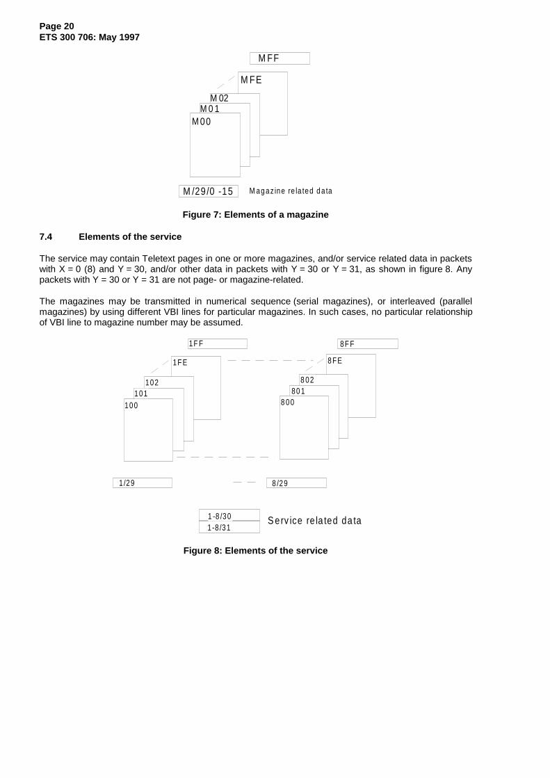
7.3 Elements of a magazine
A magazine consists of one or more pages, normally repeatedly transmitted in numerical sequence, asshown in figure 7. For editorial reasons, some pages may not be in sequence and are marked as suchusing the control bit C9 in the page header packet.
If a magazine has only one displayable page (and in some other circumstances), it may be necessary toindicate the completion of the transmission of that page by closing it with another page header packet.Headers with pages addresses in the range XFF:0000 to XFF:3F7E are defined for use for this purpose.These headers may be referred to as "Time Filling Headers", when they are used to keep the real-timeclock field updated in a magazine in parallel transmission mode.
The magazine may also contain data in packets with Y = 29. The data relates to all pages with theincluded magazine address and not to any one specific page. The data contained in such packets may beover-ridden by data contained in each page. Packets with Y = 29 are normally transmitted at least once ineach cycle of the magazine, i.e. the period after which, the numerical sequence of pages in a magazine,repeats.
Page 20ETS 300 706: May 1997
M 00M 0 1
M 02
M FF
M FE
M /29/0 -15 M ag az ine re la ted d a ta
Figure 7: Elements of a magazine
7.4 Elements of the service
The service may contain Teletext pages in one or more magazines, and/or service related data in packetswith X = 0 (8) and Y = 30, and/or other data in packets with Y = 30 or Y = 31, as shown in figure 8. Anypackets with Y = 30 or Y = 31 are not page- or magazine-related.
The magazines may be transmitted in numerical sequence (serial magazines), or interleaved (parallelmagazines) by using different VBI lines for particular magazines. In such cases, no particular relationshipof VBI line to magazine number may be assumed.
8F F
S erv ice re la ted da ta
8 /291 /29
8 02
8 00100101
10280 1
1F E
1F F
8 FE
1 -8 /301 -8 /31
Figure 8: Elements of the service

Page 21ETS 300 706: May 1997
8 Byte coding and error protection
The 8-bit bytes of data packets may be coded using one of four methods:
- 7 data bits plus one bit odd parity (see subclause 8.1).- 4 data bits plus 4 bits Hamming protection (see subclause 8.2).- 18 data bits plus 6 bits Hamming protection over 3 consecutive bytes (see subclause 8.3).- 8-bit data.
Unless otherwise stated, bytes are transmitted least significant bit first.
8.1 Odd parity
In a single 8-bit byte, bit 8 is the parity bit (P) and bits 1 to 7 carry the data bits (D). Bit 8 is set so thatthere is an odd number of bits with the value '1' in the byte. Single bit errors can be detected.
Bit 1 2 3 4 5 6 7 8D1 D2 D3 D4 D5 D6 D7 P NOTE: Bits shown in transmission order
For encoding: P = 1 ⊕ D1 ⊕ D2 ⊕ D3 ⊕ D4 ⊕ D5 ⊕ D6 ⊕ D7
For decoding: if D1 ⊕ D2 ⊕ D3 ⊕ D4 ⊕ D5 ⊕ D6 ⊕ D7 ⊕ P = 1, accept data bits
8.2 Hamming 8/4
In a single 8-bit byte, bits 1, 3, 5 and 7 are the protection bits and bits 2, 4, 6 and 8 carry the data.Single bit errors can be identified and corrected. Double bit errors can be detected.
Bit 1 2 3 4 5 6 7 8P1 D1 P2 D2 P3 D3 P4 D4 NOTE: Bits shown in transmission order
For encoding: P1 = 1 ⊕ D1 ⊕ D3 ⊕ D4
P2 = 1 ⊕ D1 ⊕ D2 ⊕ D4
P3 = 1 ⊕ D1 ⊕ D2 ⊕ D3
P4 = 1 ⊕ P1 ⊕ D1 ⊕ P2 ⊕ D2 ⊕ P3 ⊕ D3 ⊕ D4
For decoding: Four odd parity tests (A - D) on bits marked •
Parity Tests P1 D1 P2 D2 P3 D3 P4 D4A • • • •B • • • •C • • • •D • • • • • • • •
Results of Odd Parity Tests Inference ActionA, B, C D
All correct Correct No errors Accept data bitsAll correct Not correct Error in P4 Accept data bits
Not all correct Correct Double error Reject data bits
Not all correct Not correct Single error Refer to previous table to identify bitin error. Correct error if in data bit.

Page 22ETS 300 706: May 1997
8.3 Hamming 24/18
Over three consecutive 8-bit bytes, bits 1, 2, 4, 8, 16, 24 are the protection bits and the remaining bitscarry the data. Single bit errors can be identified and corrected. Double bit errors can be detected. A groupof three consecutive bytes coded in this manner is referred to as a triplet.
Byte N Byte N + 1 Byte N + 21 2 3 4 5 6 7 8 9 10 11 12 13 14 15 16 17 18 19 20 21 22 23 24
P1 P2 D1 P3 D2 D3 D4 P4 D5 D6 D7 D8 D9 D10 D11 P5 D12 D13 D14 D15 D16 D17 D18 P6
NOTE: Bits shown in transmission order.
For encoding: P1 = 1 ⊕ D1 ⊕ D2 ⊕ D4 ⊕ D5 ⊕ D7 ⊕ D9 ⊕ D11 ⊕ D12 ⊕ D14 ⊕ D16 ⊕ D18
P2 = 1 ⊕ D1 ⊕ D3 ⊕ D4 ⊕ D6 ⊕ D7 ⊕ D10 ⊕ D11 ⊕ D13 ⊕ D14 ⊕ D17 ⊕ D18
P3 = 1 ⊕ D2 ⊕ D3 ⊕ D4 ⊕ D8 ⊕ D9 ⊕ D10 ⊕ D11 ⊕ D15 ⊕ D16 ⊕ D17 ⊕ D18
P4 = 1 ⊕ D5 ⊕ D6 ⊕ D7 ⊕ D8 ⊕ D9 ⊕ D10 ⊕ D11
P5 = 1 ⊕ D12 ⊕ D13 ⊕ D14 ⊕ D15 ⊕ D16 ⊕ D17 ⊕ D18
P6 =1 ⊕ P1 ⊕ P2 ⊕ D1 ⊕ P3 ⊕ D2 ⊕ D3 ⊕ D4 ⊕ P4 ⊕ D5 ⊕ D6 ⊕ D7 ⊕ D8 ⊕ D9⊕ D10 ⊕ D11 ⊕ P5 ⊕ D12 ⊕ D13 ⊕ D14 ⊕ D15 ⊕ D16 ⊕ D17 ⊕ D18
For decoding: Six odd parity tests (A - F) on bits marked •.
Byte N Byte N + 1 Byte N + 21 2 3 4 5 6 7 8 9 10 11 12 13 14 15 16 17 18 19 20 21 22 23 24P1 P2 D1 P3 D2 D3 D4 P4 D5 D6 D7 D8 D9 D10 D11 P5 D12 D13 D14 D15 D16 D17 D18 P6
A • • • • • • • • • • • •B • • • • • • • • • • • •C • • • • • • • • • • • •D • • • • • • • •E • • • • • • • •F • • • • • • • • • • • • • • • • • • • • • • • •
Results of Odd Parity Tests Inference ActionA, B, C, D, E F
All correct Correct No errors Accept data bitsAll correct Not correct Error in P6 Accept data bits
Not all correct Correct Double error Reject data bits
Not all correct Not correct Single error Complement bit in error,see note
NOTE: The position of the bit in error is calculated from:
24 × Test E result + 23 × Test D result + 22 × Test C result + 21 × Test B result + 20 × Test A result
where A Test result = "1" if the odd parity test is failed.

Page 23ETS 300 706: May 1997
9 Coding of data packets
9.1 Overview of packet types
Table 1 summarizes the function of each type of data packet and the presentation Levels at which it isused.
Table 1: Summary of packet types, their function and application
Packet Function and application
PresentationLevel
1 1.5 2.5 3.5
X/0
(Pageheader)
Acts as both a page identifier and a page terminating packet. Decodersshould respond to packets X/0 for ALL possible page numbers and sub-codes, including those with hexadecimal elements in their address. Anypacket X/0 may be used for both time filling and page terminatingapplications.
NOTE: It is not intended that the viewer should be provided with themeans to select directly pages with hexadecimal elements in theiraddress.
~ ~ ~ ~
X/1 toX/23
(note 1)
These packets carry the display data of basic Teletext pages, coded 7data bits plus 1 odd parity bit. Other forms of coding may be used whenthe page does not carry data intended for direct display.
~ ~ ~ ~
Used for navigational purposes in the TOP Code of Practice,(see subclause 11.2).
~ ~ ~ ~
Used for pages carrying enhancement data not intended for direct display,e.g. objects definitions and DRCS data.
{ { ~ ~
X/24(note 1)
Used for navigational purposes in the FLOF Code of Practice,(see subclause 11.1).
~ ~ ~ ~
Used for pages carrying enhancement data not intended for direct display,e.g. objects definitions and DRCS data.
{ { ~ ~
X/25(note 1)
As part of a basic Teletext display page, the packet carries a number ofdisplayable labels relating to the data in the page for key-word searchapplications.
~ ~ ~ ~
Used for pages carrying enhancement data not intended for direct display,e.g. objects definitions.
{ { ~ ~
X/26/0 - 14(note 1)
Used to carry codes for programming ancillary equipment such as videorecorders, ETS 300 231 [1].
~ ~ ~ ~
Used to address character locations within a page and define newcharacters to be written to these locations. This has the action ofoverwriting the character defined for this location on the Level 1 page. ALevel 1.5 decoder may respond to some or all of the column addressgroup triplets (see subclause 12.3.4) which access the G0, G2 and G3character sets.
{ ~ { {
(continued)

Page 24ETS 300 706: May 1997
Table 1 (continued): Summary of packet types, their function and application
Packet Function and application
PresentationLevel
1 1.5 2.5 3.5
X/26/0 - 15(note 1)
Used to address character locations within a page including any side-panels. They can select and place alphanumeric and mosaics charactersfrom the G0, G1, G2 and G3 sets, redefinable characters, non-spacingattributes and objects.
{ { ~ ~
Used for object definition pages. { { ~ ~
X/27/0 Used for editorial page linking. An example of their use is the FLOF Codeof Practice, (see subclause 11.1).
~ ~ ~ ~
X/27/1 - 3 Provide additional links to editorial pages. (note 2)
X/27/4Format 1
Used for compositional page linking to objection definition and DRCSpages.
{ { ~ ~
X/27/5Format 1
Used for compositional page linking to objection definition and DRCSpages.
{ { { ~
X/27/6 - 7Format 1
Provide additional compositional links. (note 2)
X/27/4 - 7Format 2
Used for compositional page linking in data broadcasting applications { { { {
X/27/8 - 15 Use not currently defined.
X/28/0Format 1
Page specific data:
Page functionPage coding
~ ~ ~ ~
(note 3)
X/28/0Format 1
Page specific data (presentation related):
Character set designationSize and position of side-panelsColour Map (CLUTs 2 and 3)Default screen colourDefault row colourBlack background substitution by row colourColour table re-mapping of the foreground and background colours
of the Level 1 page.
{ { ~ ~
X/28/0Format 2
Page specific data for Page Format - CA type data broadcasting pagesdefined according to ETS 300 708 [2] clause 5.
{ { { {
X/28/1 Page specific data (presentation related):
Character set designation (according to earlier specifications, note 4)
{ ~ { {
(continued)

Page 25ETS 300 706: May 1997
Table 1 (continued): Summary of packet types, their function and application
Packet Function and application
PresentationLevel
1 1.5 2.5 3.5
X/28/1 Page specific data (presentation related):
DCLUT4 for global 12x10x2 DRCS mode charactersDCLUT4 for normal 12x10x2 DRCS mode charactersDCLUT16 for global 12x10x4 and 6x5x4 DRCS modes charactersDCLUT16 for normal 12x10x4 and 6x5x4 DRCS modes characters.
{ { { ~
X/28/2 Contains a Page Key for the descrambling of the encrypted datacontained in packets X/1 - X/25 of the associated data broadcastingpage. See ETS 300 708 [2].
{ { { {
X/28/3 Page specific data (related to DRCS downloading pages):
Page functionPage codingDRCS downloading mode invocation.
{ { ~ ~
X/28/4 Page specific data (presentation related):
Page functionPage codingCharacter set designationSize and position of side-panelsColour Map (CLUTs 0 and 1)Default screen colourDefault row colourBlack background substitution by row colourColour table re-mapping of the foreground and background colours
of the Level 1 page.
{ { { ~
X/28/5 - 15 Use not currently defined.
M/29/0 Same functions (apart from page function and coding) as defined forpackets X/28/0 Format 1 except that the information applies to all pagesin magazine M unless overridden for a particular page by a packet X/28/0Format 1.
{ { ~ ~
M/29/1 Character set designation (according to earlier specifications). Applies toall pages in magazine M unless overridden for a particular page by apacket X/28/1.
{ ~ { {(note 4)
M/29/2 - 3 Use not currently defined.
M/29/4 Same functions (apart from page function and coding) as defined forpackets X/28/4 except that the information applies to all pages inmagazine M unless overridden for a particular page by a packet X/28/4.
{ { { ~
M/29/5 - 15 Use not currently defined.
1 - 3/305 - 7/30
Use not currently defined, though in some countries these packets maybe in use for independent data services.
4/30 Proposed use: Audio description data for the visually impaired.
(continued)

Page 26ETS 300 706: May 1997
Table 1 (concluded): Summary of packet types, their function and application
Packet Function and application
PresentationLevel
1 1.5 2.5 3.5
8/30/0 - 1 Broadcast service data packet, Format 1. Includes multiplexed operationflag, the page number of a suitable initial page, the current time and date,network identification codes, and a text message.
~ ~ ~ ~
8/30/2 - 3 Broadcast service data packet, Format 2. Includes multiplexed operationflag, the page number of a suitable initial page, programme identificationcodes and control data for video recorders, and a text message.
~ ~ ~ ~
8/30/4 - 15 Use not currently defined.
8/31 - 3/31 Independent data services. ~ ~ ~ ~
4/31 - 7/31 Use not currently defined.
NOTE 1: Where a packet has more than one entry in this table, the precise function and coding of agiven packet is determined from the type of page to which it belongs. This may beascertained from a packet X/28/0 Format 1, if transmitted, or by the context in which thepage was referenced, e.g. a MOT entry pointing to an object definition page, or by a Codeof Practice, e.g. TOP.
NOTE 2: Application not currently defined.NOTE 3: Can form part of any page at any presentation Level to define its function and coding but
its transmission is not mandatory.NOTE 4: Function superseded by this ETS.
9.2 Reserved bits
Decoders should ignore bits and bytes which are indicated as being reserved for future use.
9.3 Directly displayable data packets
9.3.1 Page header
Page header packets (Y = 0) comprises three main elements: page address, control bits and datanormally intended for display, as shown in figure 9. The page address consists of a page number and apage sub-code.
Byte 6 7 8 9 10 11 12 13
Bytes 1 - 5 6 - 13 14 - 45
ControlBits
C11 - C14
PageNumber
Units
PageNumber
Tens
SubcodeS1
SubcodeS2
+ C4
SubcodeS4
+ C5, C6
SubcodeS3
ControlBits
C7 - C10
Page Address & Control BitsPrefix 32 Data Bytes (odd parity coded)X/0
MagazineNumber
Bytes 1 - 2 3 4 5
PacketNumber
(0)
Clock Run-InFraming
CodePacket Address
Figure 9: Format of the page header packet (X/0)

Page 27ETS 300 706: May 1997
9.3.1.1 Page number
The page number is defined by bytes 6 and 7, both Hamming 8/4 protected. The page number comprisespage units and page tens elements:
Function Byte Data Bit Weighting Range
PageUnits
62468
20
21
22
23
0 - F
PageTens
72468
20
21
22
23
0 - F
NOTE: Odd numbered data bits carry the Hamming 8/4 protection bits.
9.3.1.2 Page sub-code
The page sub-code is defined by byte 8, part of byte 9, byte 10 and part of byte 11, all Hamming 8/4protected. The page sub-code comprises four elements S1, S2, S3 and S4:
Function Byte Data Bit Weighting Range
S1(least
significant)8
2468
20
21
22
23
0 - F
S2 9246
20
21
220 - 7
S3 102468
20
21
22
23
0 - F
S4 (mostsignificant)
11 24
20
210 - 3
NOTE: Odd numbered data bits carry the Hamming 8/4 protection bits.
9.3.1.3 Control bits
The page control bits, C4 to C14, are described in table 2. They are transmitted in bytes 9, 11, 12 and 13of the page header packet and are all Hamming 8/4 protected. The control bits are active on being set to'1'.

Page 28ETS 300 706: May 1997
Table 2: Control bits in the page header
Control Bit Location Function
C4Erase Page
Byte 9, bit 8 Packets X/1 to X/28 belonging to a previous transmission of the page shouldbe erased from the decoder's memory before packets belonging to theassociated page are stored.
C5Newsflash
Byte 11, bit6
When set to '1' this bit indicates that the associated page is a Newsflashpage. All information intended for display on such a page will be boxed andwill be displayed inset into the normal video picture.
C6Subtitle
Byte 11, bit8
When set to '1' this bit indicates that the associated page is a subtitle page.All information intended for display on such a page will be boxed and will bedisplayed inset into the normal video picture.
C7SuppressHeader
Byte 12, bit2
Data addressed to row 0 is not to be displayed.
C8Update
Indicator
Byte 12, bit4
Data within packets X/1 to X/28 of the associated page has been changedsince the previous transmission. The setting of this bit is under editorialcontrol.
C9InterruptedSequence
Byte 12, bit6
The associated page is not in numerical order of page sequence, allowingthe header to be excluded from a rolling header display to avoiddiscontinuities.
C10Inhibit Display
Byte 12, bit8
Data addressed to rows 1 to 24 is not to be displayed.
C11Magazine Serial
Byte 13, bit2
When set to '1' the service is designated to be in Serial mode and thetransmission of a page is terminated by the next page header with a differentpage number.
When set to '0' the service is designated to be in Parallel mode and thetransmission of a page is terminated by the next page header with a differentpage number but the same magazine number.
The same setting shall be used for all page headers in the service.
C12, C13, C14National Option
CharacterSubset
Byte13, bits 4, 6
and 8
Where the decoder is capable of displaying text in more than one languagethese control bits are used to select G0 character set options, (seesubclause 15.2). The response to these control bits may be modified bypackets X/28/0 Format 1, X/28/4, M/29/0 and M/29/4.
9.3.1.4 Data bytes
Bytes 14 to 45 in page header packets carry 32 character or display control codes, coded 7 data bits plusone bit odd parity. They are normally intended for display. Bytes 38 to 45 are usually coded to represent areal-time clock.

Page 29ETS 300 706: May 1997
9.3.2 Packets X/1 to X/25
Packets X/1 to X/25 intended for direct display are coded according to figure 10.
Bytes 1 - 5 6 - 45
Prefix 40 Data Bytes (odd parity coded)X/1 - 25
MagazineNumber
Bytes 1 - 2 3 4 5
PacketNumber(1 - 25)
Clock Run-InFraming
CodePacket Address
Figure 10: Format of packets X/1 to X/25 for direct display
The same coding is used for the packets X/1 to X/24 of DRCS data pages. Different coding schemes areused for packets X/1 to X/25 when they form part of pages not intended for direct display such as Objectdefinition pages (see subclause 10.5.1), magazine inventory pages (see subclause 11.3), the additionaldata pages used in the "TOP" system (see subclause 11.2), and for data broadcasting, ETS 300 708 [2].
9.4 Page enhancement data packets
Packets X/26, X/28 and M/29 can carry data to enhance a basic Level 1 Teletext page. The generalcoding scheme is shown in figure 11. Byte 6 is used as an additional address byte (designation code),coded Hamming 8/4. This allows up to 16 versions of each packet type. The remaining 39 bytes areHamming 24/18 coded, grouped as 13 triplets.
Bytes 1 - 5 6 7 - 9 10 - 12 43 - 45X/26X/28M/29
Prefix
Byte 6
DesignationCode
Byte 3N + 4 3N + 5 3N + 6
Triplet N (N = 1 to 13) Hamming 24/18 coded
Triplet 1 Triplet 2 Triplet 13Triplet NDC
MagazineNumber
Bytes 1 - 2 3 4 5
PacketNumber
Clock Run-InFraming
Code Packet Address
Figure 11: Format of packets X/26, X/28 and M/29
NOTE: Packets X/1 to X/25 of POPs and GPOPs use the same coding scheme for bytes 7 to45. Byte 6 is Hamming 8/4 coded but does not have the function of a designation code(see subclauses 10.5.1.2 and 10.5.1.3).

Page 30ETS 300 706: May 1997
9.4.1 Packet X/26
Packets X/26 are used for:
- at presentation Levels 1.5, 2.5, 3.5: addressing a character location and overwriting the existingcharacter defined on the Level 1 page;
- at presentation Levels 2.5, 3.5: modifying existing display attributes and for object definitions;
- at all presentation Levels:VCR programming, see ETS 300 231 [1].
Designation code values 0000 to 1111 allow up to 16 packets with Y = 26 to be associated with a givenpage.
Unlike other page enhancement packets, the function of a data bit within a packet X/26 is not determinedby its overall position within the packet. The coding and function of the data bits of packets X/26 isdescribed in subclause 12.3.
9.4.2 Packet X/28/0 Format 1
9.4.2.1 Page Function and Page Coding
A Format 1 packet X/28 with a designation code value of 0000 may be transmitted as part of any page atany presentation level. The first 7 data bits of the packet define the function and the coding of packets X/1to X/25 of the associated page, as shown in table 3. This coding scheme is also used for the first 7data bits of packets X/28/3 and X/28/4.
Table 3: Page function and page coding bits (packets X/28/0 Format 1, X/28/3 and X/28/4)
Triplet Bits Function
1 1-4 Page Function
These bits define the function of the data in packets X/1 to X/25 of the associated page.
Bit4 3 2 1 Page Function
0 0 0 0 Basic Level 1 Teletext page (LOP)
0 0 0 1 Data broadcasting page coded according to ETS 300 708 [2] clause 4
0 0 1 0 Global Object definition page (GPOP) - (see subclause 10.5.1)
0 0 1 1 Normal Object definition page (POP) - (see subclause 10.5.1)
0 1 0 0 Global DRCS downloading page (GDRCS) - (see subclause 10.5.2)
0 1 0 1 Normal DRCS downloading page (DRCS) - (see subclause 10.5.2)
0 1 1 0 Magazine Organization table (MOT) - (see subclause 10.6)
0 1 1 1 Magazine Inventory page (MIP) - (see subclause 11.3)
1 0 0 0 Basic TOP table (BTT) }
1 0 0 1 Additional Information Table (AIT) } (see subclause 11.2)
1 0 1 0 Multi-page table (MPT) }
1 0 1 1 Multi-page extension table (MPT-EX) }
Other combinations are reserved for future use.
(continued)

Page 31ETS 300 706: May 1997
Table 3 (concluded): Page function and page coding bits (packets X/28/0 Format 1,X/28/3 and X/28/4)
Triplet Bits Function
1 5-7 Page Coding
These bits define the coding of packets X/1 to X/25 of the associated page.
Bit
7 6 5 Page Coding
0 0 0 All 8-bit bytes, each comprising 7 data bits and 1 odd parity bit.
0 0 1 All 8-bit bytes, each comprising 8 data bits.
0 1 0 Per packet: One 8-bit byte coded Hamming 8/4, followed by thirteengroups of three 8-bit bytes coded Hamming 24/18. All packets coded inthis way.
0 1 1 All 8-bit bytes, each code Hamming 8/4.
1 0 0 Per packet: Eight 8-bit bytes coded Hamming 8/4, followed by twelve 8-bit bytes coded 7 data bits and 1 odd parity bit. This sequence is thenrepeated for the remaining 20 bytes. All packets coded in this way.
1 0 1 Per packet: First 8-bit byte coded Hamming 8/4. The data bits fromthis byte define the coding of the remaining 39 bytes of this packet only,according to the first five entries in this table.
Other combinations are reserved for future use.
9.4.2.2 Coding for basic Level 1 Teletext pages
When the Page Function bits (triplet 1, bits 1 to 4) indicate a basic Level 1 Teletext page (code 0000), theremaining bits of the packet define the following Level 2.5 and 3.5 presentation related data:
- Default character sets;- Size and position of any side-panels;- Colour map entry coding for CLUTs 2 and 3;- Default screen and row colours;- Colour table re-mapping of the foreground and background colours of the basic Level 1 page.
The coding is shown in table 4. The same coding also applies to packets X/28/4 except that they redefineCLUTs 0 and 1 instead of CLUTs 2 and 3.
Where packets 28/0 and 28/4 are both transmitted as part of a page, packet 28/0 takes precedence over28/4 for all but the colour map entry coding.

Page 32ETS 300 706: May 1997
Table 4: Coding of packet X/28/0 Format 1 for basic Level 1 pages
Triplet Bits Function
1 1-4 Page Function = Basic Level 1 Teletext page (see subclause 9.4.2.1).
1 5-7 Page Coding = All 8-bit bytes, each comprising 7 bits data and 1 odd parity bit(see subclause 9.4.2.1).
1 8-14 Default G0 and G2 Character Set Designation and National Option Selection
Default G0 primary and G2 supplementary character sets plus national option charactersub-sets are designated. The 7-bit value is used to select an entry in table 32.
NOTE: The default character sets at the start of each row are the default G0 andG2 sets. In some transmissions, each "ESC" control character (code 1/B)on the Level 1 page toggles the G0 set between the default and second G0sets for the subsequent G0 characters of the row.
1
2
15-18
1-3
Second G0 Set Designation and National Option Selection
A second G0 character set and a national option sub-set are designated. The 7-bit value isused to select an entry in table 33. See previous note.
2 4 Left Side Panel
0 = No left side panel is to be displayed; 1 = Left side panel is to be displayed.
2 5 Right Side Panel
0 = No right side panel is to be displayed; 1 = Right side panel is to be displayed.
2 6 Side Panel Status Flag
0 = Side panel(s) required at Level 3.5 only; 1 = Side panel(s) required at Levels 2.5 & 3.5.
2 7-10 Number of Columns in Side Panels
Bits 7 to 10 (LSB to MSB) define the number of columns in the left side panel. If the rightside-panel is to be displayed, its width (in columns) is 16 minus this value. When only oneside panel is in use, a value of 0 indicates a side panel of 16 columns.
2
3-12
13
11-18
1-18
1-4
Colour Map Entry Coding for CLUTs 2 and 3
The bits are organized as 16 data words, each of 12 bits. Each word defines an entry inthe Colour Map of subclause 12.4, proceeding in transmission order from CLUT 2, entry 0to CLUT 3, entry 7. Each 12-bit data word contains 4 bits for each primary colour (Red,Green and Blue), in the transmission order: RRRRGGGGBBBB, with ascending orderof bit significance within each 4 bits.
13 5-9 Default Screen Colour
Selects an entry in the Colour Map of subclause 12.4 to be applied to the screen areaabove display row 0 and below row 23, or 24 if used. Screen colour selection via a packetX/26 takes priority over this value.
13 10-14 Default Row Colour
Selects an entry in the Colour Map of subclause 12.4 to be applied to rows 0 to 23, and 24where used. Row colour selection via a packet X/26 takes priority over this value.
(continued)
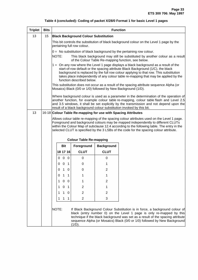
Page 33ETS 300 706: May 1997
Table 4 (concluded): Coding of packet X/28/0 Format 1 for basic Level 1 pages
Triplet Bits Function
13 15 Black Background Colour Substitution
This bit controls the substitution of black background colour on the Level 1 page by thepertaining full row colour.
0 = No substitution of black background by the pertaining row colour.
NOTE: This black background may still be substituted by another colour as a resultof the Colour Table Re-mapping function, see below.
1 = On any row where the Level 1 page displays a black background as a result of thestart-of-row default or the spacing attribute Black Background (1/C), the blackbackground is replaced by the full row colour applying to that row. This substitutiontakes place independently of any colour table re-mapping that may be applied by thefunction described below.
This substitution does not occur as a result of the spacing attribute sequence Alpha (orMosaics) Black (0/0 or 1/0) followed by New Background (1/D).
Where background colour is used as a parameter in the determination of the operation ofanother function, for example colour table re-mapping, colour table flash and Level 2.5and 3.5 windows, it shall be set explicitly by the transmission and not depend upon theresult of a black background colour substitution invoked by this bit.
13 16-18 Colour Table Re-mapping for use with Spacing Attributes
Allows colour table re-mapping of the spacing colour attributes used on the Level 1 page.Foreground and background colours may be mapped independently to different CLUTswithin the Colour Map of subclause 12.4 according to the following table. The entry in theselected CLUT is specified by the 3 LSBs of the code for the spacing colour attribute.
Colour Table Re-mapping
Bit Foreground Background
18 17 16 CLUT CLUT
0 0 0 0 0
0 0 1 0 1
0 1 0 0 2
0 1 1 1 1
1 0 0 1 2
1 0 1 2 1
1 1 0 2 2
1 1 1 2 3
NOTE: If Black Background Colour Substitution is in force, a background colour ofblack (entry number 0) on the Level 1 page is only re-mapped by thistechnique if the black background was set as a result of the spacing attributesequence Alpha (or Mosaics) Black (0/0 or 1/0) followed by New Background(1/D).

Page 34ETS 300 706: May 1997
9.4.2.3 Coding for data broadcasting pages
The coding of table 5 applies to the data bits of a packet X/28/0 Format 1 when the Page Function bitsindicate a page a data broadcasting page (code 0001).
Table 5: Coding of Packet X/28/0 Format 1 for Data Broadcasting Pages
Triplet Bits Function
1 1-4 Page Function = Data broadcasting page (see subclause 9.4.2.1).
1 5-7 Page Coding - defined according to subclause 9.4.2.1.
1 8-18 Set to 11111111100 (bits 8 to 18). This value is chosen to ensure existing databroadcasting decoders, designed according to ETS 300 708 [2], ignore this type of page.
2-13 1-18 Define by the data broadcasting application.
9.4.2.4 Coding for other types of page
The coding of table 6 applies to the data bits of a packet X/28/0 Format 1 when the Page Function bitsindicate a page other than a basic Level 1 Teletext page (code 0000) or a data broadcasting page(code 0001).
Table 6: Coding of Packet X/28/0 Format 1 for other types of pages
Triplet Bits Function
1 1-4 Page Function - defined according to subclause 9.4.2.1.
1 5-7 Page Coding - defined according to subclause 9.4.2.1.
1 8-18 Set to 11111111100 (bits 8 to 18). This value is chosen to ensure existing databroadcasting decoders, designed according to ETS 300 708 [2], ignore this type of page.
2-13 1-18 Reserved for future use.
9.4.3 Packet X/28/0 - Format 2
A packet X/28/0 Format 2 is used in data broadcasting applications as part of the Page Format - CAprotocol defined in ETS 300 708 [2] clause 5. The first 8 data bits of the packet define the function of theassociated page, and bits 15 to 18 define the coding of packets X/1 to X/25, as shown in table 7. Thiscoding scheme is also used for the first triplet of packets X/28/2.
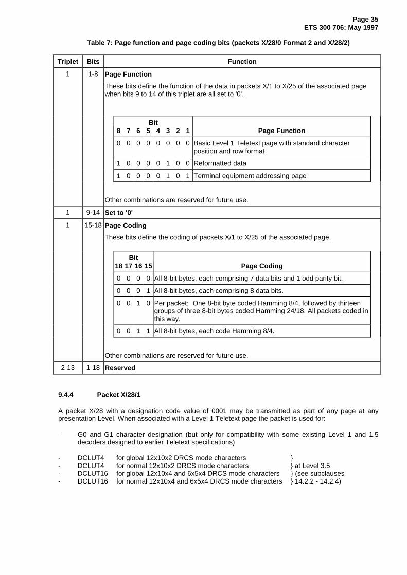
Page 35ETS 300 706: May 1997
Table 7: Page function and page coding bits (packets X/28/0 Format 2 and X/28/2)
Triplet Bits Function
1 1-8 Page Function
These bits define the function of the data in packets X/1 to X/25 of the associated pagewhen bits 9 to 14 of this triplet are all set to '0'.
Bit8 7 6 5 4 3 2 1 Page Function
0 0 0 0 0 0 0 0 Basic Level 1 Teletext page with standard characterposition and row format
1 0 0 0 0 1 0 0 Reformatted data
1 0 0 0 0 1 0 1 Terminal equipment addressing page
Other combinations are reserved for future use.
1 9-14 Set to '0'
1 15-18 Page Coding
These bits define the coding of packets X/1 to X/25 of the associated page.
Bit18 17 16 15 Page Coding
0 0 0 0 All 8-bit bytes, each comprising 7 data bits and 1 odd parity bit.
0 0 0 1 All 8-bit bytes, each comprising 8 data bits.
0 0 1 0 Per packet: One 8-bit byte coded Hamming 8/4, followed by thirteengroups of three 8-bit bytes coded Hamming 24/18. All packets coded inthis way.
0 0 1 1 All 8-bit bytes, each code Hamming 8/4.
Other combinations are reserved for future use.
2-13 1-18 Reserved
9.4.4 Packet X/28/1
A packet X/28 with a designation code value of 0001 may be transmitted as part of any page at anypresentation Level. When associated with a Level 1 Teletext page the packet is used for:
- G0 and G1 character designation (but only for compatibility with some existing Level 1 and 1.5decoders designed to earlier Teletext specifications)
- DCLUT4 for global 12x10x2 DRCS mode characters }- DCLUT4 for normal 12x10x2 DRCS mode characters } at Level 3.5- DCLUT16 for global 12x10x4 and 6x5x4 DRCS mode characters } (see subclauses- DCLUT16 for normal 12x10x4 and 6x5x4 DRCS mode characters } 14.2.2 - 14.2.4)

Page 36ETS 300 706: May 1997
The coding shown in table 8 applies when the packet forms part of a basic Level 1 page.
Table 8: Coding of Packet X/28/1
Triplet Bits Function
1 1-2 Set to '00'. (note)
1 3-9 Character Set Code for G0 Table. (note)
1 10 Set to '0'. (note)
1 11-17 Character Set Code for G1 Table. (note)
1 18 Set to '0'. (note)
2
3
1-18
1-2
DCLUT4 for Global 12x10x2 DRCS Mode Characters
4 data words of 5 bits each to define the DCLUT for use with global 12x10x2 DRCS.
The transmission order is least significant bit first.
3
4
3-18
1-4
DCLUT4 for Normal 12x10x2 DRCS Mode Characters
4 data words of 5 bits each to define the DCLUT for use with normal 12x10x2 DRCS.
The transmission order is least significant bit first.
4
5-7
8
5-18
1-18
1-12
DCLUT16 for Global 12x10x4 and 6x5x4 DRCS Mode Characters
16 data words of 5 bits each to define the DCLUT for use with global 12x10x4 and 6x5x4DRCS. The transmission order is least significant bit first.
8
9-12
13
13-18
1-18
1-2
DCLUT16 for Normal 12x10x4 and 6x5x4 DRCS Mode Characters
16 data words of 5 bits each to define the DCLUT for use with global 12x10x4 and 6x5x4DRCS. The transmission order is least significant bit first.
13 3-18 Reserved for future use
NOTE: The function of these bits is defined by earlier specifications and is retained for compatibilitywith existing Level 1 and 1.5 decoders designed to them. They are not intended for use byLevel 2.5 and 3.5 decoders designed to this ETS.
9.4.5 Packet X/28/2
A packet X/28 with a designation code value of 0010 may be transmitted as part of any page at anypresentation Level. It is used to carry a Page Key for descrambling purposes in certain data broadcastingapplications, (see ETS 300 708 [2], subclause 5.4.2). The first triplet is coded in an identical manner to apacket X/28/0 Format 2, as shown in table 7.
9.4.6 Packet X/28/3
A packet X/28 with a designation code value of 0011 may be transmitted as part of a DRCS downloadingpage at presentation Levels 2.5 and 3.5. The first 7 data bits of the packet define the function and thecoding of packets X/1 to X/25 of the associated page according to subclause 9.4.2.1.
The coding of table 9 applies to the remaining data bits of the packet when the Page Function bits (triplet1, bits 1 to 4) indicate a global or normal DRCS downloading page (codes 0100 and 0101). The type ofDRCS character defined by each pattern transfer unit (PTU) transmitted via packets X/1 to X/24 isspecified.

Page 37ETS 300 706: May 1997
Table 9: Coding of Packet X/28/3 for DRCS Downloading Pages
Triplet Bits Function
1 1-7 Coded according to subclause 9.4.2.1.
Page Function = 0100 or 0101 (Global or normal DRCS downloading page)
Page Coding = 000 (7 bits plus odd parity)
1 8-18 Reserved for future use.
2-11
12
1-18
1-12
DRCS Downloading Mode Invocation
The downloading mode of DRCS characters at Level 3.5 are specified individually foreach character. These 192 data bits are used to transmit 48 Mode Identification codes,each comprising 4 bits. One value is assigned to each Pattern Transfer Unit (PTU) of20 bytes.
Bits DRCS(MSB LSB) Mode Resolution or Function
0 0 0 0 0 12 x 10 x 1
0 0 0 1 1 12 x 10 x 2
0 0 1 0 2 12 x 10 x 4
0 0 1 1 3 6 x 5 x 4
1 1 1 0 Subsequent PTU of a Mode 1 or 2 character
1 1 1 1 No data for the corresponding character
Other values are reserved.
Where a DRCS character is defined by more than one PTU, the appropriate mode valueis used for the first PTU and subsequent PTUs are coded 1110.
12
13
13-18
1-18
Reserved for future use
9.4.7 Packet X/28/4
A packet X/28 with a designation code value of 0100 may be transmitted as part of any page atpresentation Level 3.5. The first 7 data bits of the packet define the function and the coding of packets X/1to X/25 of the associated page according to subclause 9.4.2.1.
When the Page Function bits (triplet 1, bits 1 to 4) indicate a Level 1 Teletext page (code 0000), theremaining bits of the packet define the following Level 2.5 and 3.5 presentation related data:
- Default character sets;- Size and position of any side-panels;- Colour map entry coding for CLUTs 0 and 1;- Default screen and row colours;
Colour table re-mapping of the foreground and background colours of the Level 1 page.The coding is shown in table 10. It is identical to packets X/28/0 Format 1 except that it redefines CLUTs 2and 3 instead of CLUTs 0 and 1.
Where packets 28/0 and 28/4 are both transmitted as part of a page, packet 28/0 takes precedence over28/4 for all but the colour map entry coding.

Page 38ETS 300 706: May 1997
Table 10: Coding of packet X/28/4 for basic Level 1 pages
Triplet Bits Function
1 1-7 Page Function and Page Coding. As subclause 9.4.2.1.
1 8-14 Default G0 and G2 Character Set Designation and National Option Selection
As subclause 9.4.2.2.
1
2
15-18
1-3
Second G0 Set Designation and National Option Selection. As subclause 9.4.2.2.
2 4 Left Side Panel. As subclause 9.4.2.2.
2 5 Right Side Panel. As subclause 9.4.2.2.
2 6 Side Panel Status Flag. As subclause 9.4.2.2.
2 7-10 Number of Columns in Side Panels. As subclause 9.4.2.2.
2
3-12
13
11-18
1-18
1-4
Colour Map Entry Coding for CLUTs 0 and 1
The bits are organized as 16 data words, each of 12 bits. Each word defines an entry inthe Colour Map of subclause 12.4, proceeding in transmission order from CLUT 0, entry 0to CLUT 1, entry 7. Each 12 bit data word contains 4 bits for each primary colour (Red,Green and Blue), in the transmission order: RRRRGGGGBBBB, with ascending orderof bit significance within each 4 bits.
CLUT 1, entry 0 is always "transparent". The corresponding bits for this entry should beignored by decoders.
13 5-9 Default Screen Colour. As subclause 9.4.2.2.
13 10-14 Default Row Colour. As subclause 9.4.2.2.
13 15 Black Background Colour Substitution. As subclause 9.4.2.2.
13 16-18 Colour Table Re-mapping for use with Spacing Attributes. As subclause 9.4.2.2.
9.5 Magazine-Related Page Enhancement Data Packets
9.5.1 Packet M/29/0
The coding of the bits applicable to character set designation, side-panels, the CLUT, default row andscreen colours, colour table re-mapping and black background substitution in packets X/28/0 Format 1 isalso used in packets M/29/0. This data applies to all basic Level 1 pages in magazine M but is overriddenfor a particular page if a packet X/28/0 Format 1 exists for that page. Where M/29/0 and M/29/4 aretransmitted for the same magazine, M/29/0 takes precedence over M/29/4.

Page 39ETS 300 706: May 1997
Table 11: Coding of Packet M/29/0
Triplet Bits Function
1 1-7 Packet Function
These bits define the application and scope of the data bits in the remainder of thispacket.
Bits7 6 5 4 3 2 1 Packet Function
0 0 0 0 0 0 0 The remaining data bits have an identical coding andfunction to those of packet X/28/0 Format 1(see subclause 9.4.2) except that here the data applies to allpages in magazine M.
All other values are reserved for future use.
1 8-14 Default G0 and G2 Character Set Designation and National Option Selection
As subclause 9.4.2.2.
1
2
15-18
1-3
Second G0 Set Designation and National Option Selection. As subclause 9.4.2.2.
2 4 Left Side Panel. As subclause 9.4.2.2.
2 5 Right Side Panel. As subclause 9.4.2.2.
2 6 Side Panel Status Flag. As subclause 9.4.2.2.
2 7-10 Number of Columns in Side Panels. As subclause 9.4.2.2.
2
3-12
13
11-18
1-18
1-4
Colour Map Entry Coding for CLUTs 2 and 3. As subclause 9.4.2.2.
13 5-9 Default Screen Colour. As subclause 9.4.2.2.
13 10-14 Default Row Colour. As subclause 9.4.2.2.
13 15 Black Background Colour Substitution. As subclause 9.4.2.2.
13 16-18 Colour Table Re-mapping for use with Spacing Attributes. As subclause 9.4.2.2.
9.5.2 Packet M/29/1
The coding used for X/28/1 is also used for packets M/29/1. This data applies to all Level 1 pages inmagazine M but is overridden for a particular page if a packet X/28/1 exists for that page.

Page 40ETS 300 706: May 1997
Table 12: Coding of Packet M/29/1
Triplet Bits Function
1 1-18 Character Set Codes for G0 and G1 Tables. As subclause 9.4.4.
2
3
1-18
1-2
DCLUT4 for Global 12x10x2 DRCS Mode Characters.
As subclause 9.4.4.
3
4
3-18
1-4
DCLUT4 for Normal 12x10x2 DRCS Mode Characters.
As subclause 9.4.4.
4
5-7
8
5-18
1-18
1-12
DCLUT16 for Global 12x10x4 and 6x5x4 DRCS Mode Characters. As subclause 9.4.4.
8
9-12
13
13-18
1-18
1-2
DCLUT16 for Normal 12x10x4 and 6x5x4 DRCS Mode Characters. As subclause 9.4.4.
13 3-18 Reserved for future use
9.5.3 Packet M/29/4
The coding of the bits applicable to character set designation, side-panels, the CLUT, default row andscreen colours, colour table re-mapping and black background substitution in packets X/28/4 is also usedin packets M/29/4. This data applies to all basic Level 1 pages in magazine M but is overridden for aparticular page if a packet X/28/4 exists for that page. Where M/29/0 and M/29/4 are transmitted for thesame magazine, M/29/0 takes precedence over M/29/4.
Table 13: Coding of Packet M/29/4
Triplet Bits Function
1 1-7 Packet Function
These bits define the application and scope of the data bits in the remainder of thispacket.
Bit7 6 5 4 3 2 1 Packet Function
0 0 0 0 0 0 0 The remaining data bits of this packet have an identicalcoding and function to those of packet X/28/4(see subclause 9.4.7) except that here the data applies toall pages in magazine M.
All other values are reserved for future use.
1 8-14 Default G0 and G2 Character Set Designation and National Option Selection
As subclause 9.4.2.2.
1
2
15-18
1-3
Second G0 Set Designation and National Option Selection. As subclause 9.4.2.2.
(continued)

Page 41ETS 300 706: May 1997
Table 13 (concluded): Coding of Packet M/29/4
Triplet Bits Function
2 4 Left Side Panel. As subclause 9.4.2.2.
2 5 Right Side Panel. As subclause 9.4.2.2.
2 6 Side Panel Status Flag. As subclause 9.4.2.2.
2 7-10 Number of Columns in Side Panels. As subclause 9.4.2.2.
2
3-12
13
11-18
1-18
1-4
Colour Map Entry Coding for CLUTs 0 and 1
The bits are organized as 16 data words, each of 12 bits. Each word defines an entryin the Colour Map of subclause 12.4, proceeding in transmission order from CLUT 0,entry 0 to CLUT 1, entry 7. Each 12 bit data word contains 4 bits for each primarycolour (Red, Green and Blue), in the transmission order: RRRRGGGGBBBB, withascending order of bit significance within each 4 bits.
CLUT 1, entry 0 is always "transparent". The corresponding bits for this entry shouldbe ignored by decoders.
13 5-9 Default Screen Colour. As subclause 9.4.2.2.
13 10-14 Default Row Colour. As subclause 9.4.2.2.
13 15 Black Background Colour Substitution. As subclause 9.4.2.2.
13 16-18 Colour Table Re-mapping for use with Spacing Attributes. As subclause 9.4.2.2.
9.6 Packets for Page Linking
9.6.1 Packets X/27/0 to X/27/3 for Editorial Linking
Packets X/27 with designation codes in the range 0000 to 0011 define editorially linked pages. Codes ofPractice exist for user-friendly page access methods. To support certain methods, a decoder is requiredto respond to the linked page data in packets X/27/0 and the display data in packets X/24(see subclause 11.1).
The structure of packets X/27/0 - 3 is shown in figure 12.
Bytes 1 - 5 6 7 - 12 13 - 18 19 - 24 25 - 30 31 - 36 37 - 42 43 44 - 45
PrefixX/27/0 - 3
Byte 6N + 7 6N + 8 6N + 9 6N + 10 6N + 11 6N + 12
PageNumber
Units
PageNumber
Tens
SubcodeS1
SubcodeS2
+ M1
SubcodeS4
+ M2, M3
SubcodeS3
Byte 6
DesignationCode (0 - 3)
DC
Link 1Link 0 Link 2 Link 3 Link 4 Link 5 CRCLC
LinkControl
Link N (N = 0 to 5)
MagazineNumber
Bytes 1 - 2 3 4 5
PacketNumber
(27)
Clock Run-InFraming
CodePacket Address
Figure 12: Format of packets X/27/0-3 for editorial links
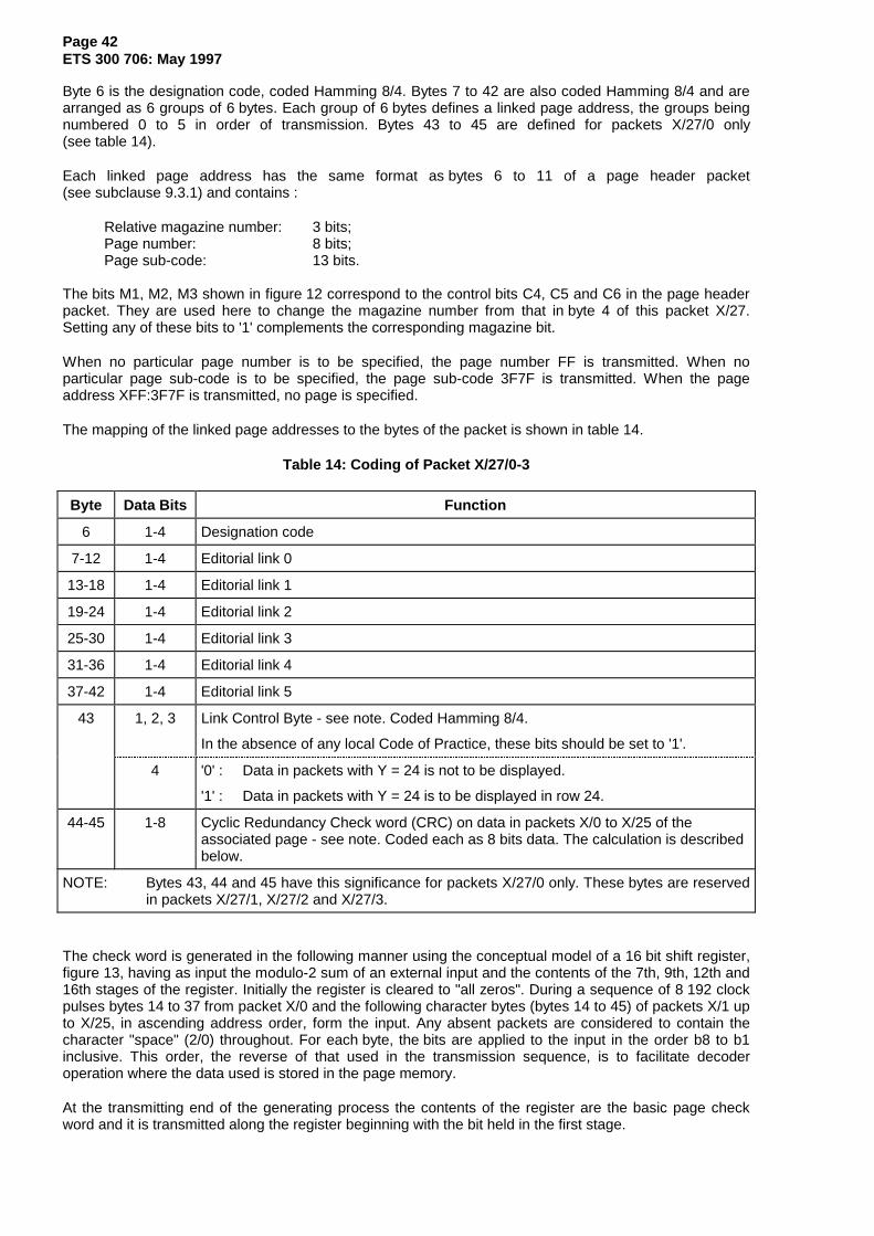
Page 42ETS 300 706: May 1997
Byte 6 is the designation code, coded Hamming 8/4. Bytes 7 to 42 are also coded Hamming 8/4 and arearranged as 6 groups of 6 bytes. Each group of 6 bytes defines a linked page address, the groups beingnumbered 0 to 5 in order of transmission. Bytes 43 to 45 are defined for packets X/27/0 only(see table 14).
Each linked page address has the same format as bytes 6 to 11 of a page header packet(see subclause 9.3.1) and contains :
Relative magazine number: 3 bits;Page number: 8 bits;Page sub-code: 13 bits.
The bits M1, M2, M3 shown in figure 12 correspond to the control bits C4, C5 and C6 in the page headerpacket. They are used here to change the magazine number from that in byte 4 of this packet X/27.Setting any of these bits to '1' complements the corresponding magazine bit.
When no particular page number is to be specified, the page number FF is transmitted. When noparticular page sub-code is to be specified, the page sub-code 3F7F is transmitted. When the pageaddress XFF:3F7F is transmitted, no page is specified.
The mapping of the linked page addresses to the bytes of the packet is shown in table 14.
Table 14: Coding of Packet X/27/0-3
Byte Data Bits Function
6 1-4 Designation code
7-12 1-4 Editorial link 0
13-18 1-4 Editorial link 1
19-24 1-4 Editorial link 2
25-30 1-4 Editorial link 3
31-36 1-4 Editorial link 4
37-42 1-4 Editorial link 5
43 1, 2, 3 Link Control Byte - see note. Coded Hamming 8/4.
In the absence of any local Code of Practice, these bits should be set to '1'.
4 '0' : Data in packets with Y = 24 is not to be displayed.
'1' : Data in packets with Y = 24 is to be displayed in row 24.
44-45 1-8 Cyclic Redundancy Check word (CRC) on data in packets X/0 to X/25 of theassociated page - see note. Coded each as 8 bits data. The calculation is describedbelow.
NOTE: Bytes 43, 44 and 45 have this significance for packets X/27/0 only. These bytes are reservedin packets X/27/1, X/27/2 and X/27/3.
The check word is generated in the following manner using the conceptual model of a 16 bit shift register,figure 13, having as input the modulo-2 sum of an external input and the contents of the 7th, 9th, 12th and16th stages of the register. Initially the register is cleared to "all zeros". During a sequence of 8 192 clockpulses bytes 14 to 37 from packet X/0 and the following character bytes (bytes 14 to 45) of packets X/1 upto X/25, in ascending address order, form the input. Any absent packets are considered to contain thecharacter "space" (2/0) throughout. For each byte, the bits are applied to the input in the order b8 to b1inclusive. This order, the reverse of that used in the transmission sequence, is to facilitate decoderoperation where the data used is stored in the page memory.
At the transmitting end of the generating process the contents of the register are the basic page checkword and it is transmitted along the register beginning with the bit held in the first stage.

Page 43ETS 300 706: May 1997
The transmission order for the two byte group resulting from the 16-bit cyclic redundancy check on thepage is bits 9 to 16 followed by bits 1 to 8 inclusive.
16-bit shift register
1 2 3 4 5 6 7 8 9 10 11 12 13 14 15 16
Modulo 2 Adder
Externalinput
Output
Clear
Clock
Figure 13: Check word generation
9.6.2 Packets X/27/4 and X/27/5 - Format 1 - for compositional linking in presentationenhancement applications
Format 1 packets X/27 have valid designation codes of 0100 and 0101. The packets define compositionallinks to enhancement data pages (i.e. DRCS downloading pages and object definition pages) at Levels2.5 and 3.5.
The structure of Format 1 packets X/27/4 and X/27/5 is shown in figure 14.
Bytes 1 - 5 6 7 - 9 10 - 12 13 - 15 16 - 18 43 - 45
X/27/4X/27/5
Prefix
Byte 6
DesignationCode
ReservedTriplet 13
Byte 3N + 4 3N + 5 3N + 6
Triplet N (N = 1 to 13) Hamming (24/18) coded
DC
Link 0Triplet 1 Triplet 2 Triplet 3 Triplet 4
Link 1
MagazineNumber
Bytes 1 - 2 3 4 5
PacketNumber
(27)
Clock Run-InFraming
Code Packet Address
Triplet N Triplet N+1Link M
Figure 14: Format of Format 1 packets X/27/4 and X/27/5 for compositional linking
Byte 6 is the designation code, coded Hamming 8/4. Bytes 7 to 42 are arranged as 6 groups of3 + 3 bytes, each sub-group of 3 bytes being one Hamming 24/18 coded triplet. Each group of 6 bytesdefines a linked page address, the groups being numbered 0 to 5 in order of transmission. Bytes 43 to 45are also Hamming 24/18 coded but the data bits are reserved for future use.
Each linked page address of 3 + 3 bytes contains 36 data bits:
Relative magazine number: 3 bits;Page number: 8 bits;Page sub-code flags: 16 bits;Link function flags: 4 bits;Compatibility bits 2 bits;Reserved: 3 bits.
The mapping of these functions within a two triplet group, and the allocation of links to triplets, is shown intable 15.

Page 44ETS 300 706: May 1997
Table 15: Coding of Packets X/27/4 and X/27/5, Format 1
Triplet Data Bits Function
1-2 1-18 Link 0
1 1-2 Link Function
These bits define the type of page being linked.
Bit 2 Bit 1 Link Function
0 0 Link to GPOP
0 1 Link to POP
1 0 Link to GDRCS
1 1 Link to DRCS
1 3-4 Page Validity
These bits define the presentation Levels requiring the linked page.
Bit 4 Bit 3 Page Validity
0 0 Reserved for future use
0 1 Page required at Level 2.5 only
1 0 Page required at Level 3.5 only
1 1 Page required at both Level 2.5 and 3.5
1 5-6 Reserved for future use
1 7-10 Page Number Units (LSB - MSB)
1 11 Set to '1' (for compatibility with Format 2 packets X/27/4-7)
1 12-14 Relative Magazine Number (LSB - MSB).
These bits change the magazine number from that in byte 4 of this packet X/27.Setting any of these bits to '1' complements the corresponding magazine bit.
1 15-18 Page Number Tens (LSB - MSB)
(continued)

Page 45ETS 300 706: May 1997
Table 15 (concluded): Coding of Packets X/27/4 and X/27/5, Format 1
Triplet Data Bits Function
2 1 Set to '0' (for compatibility with Format 2 packets X/27/4-7)
2 2 Reserved for future use
2 3-18 Page Sub-code Flags
These bits indicate the specific sub-pages required:
'0' = Not required; '1' = Required.
Data bits 3 4 5 6 7 8 9 10 11 12 13 14 15 16 17 18S1 sub-code value 0 1 2 3 4 5 6 7 8 9 10 11 12 13 14 15
3-4 1-18 Link 1 , coded the same as triplets 1 and 2.
5-6 1-18 Link 2 , coded the same as triplets 1 and 2.
7-8 1-18 Link 3 , coded the same as triplets 1 and 2.
9-10 1-18 Link 4 , coded the same as triplets 1 and 2.
11-12 1-18 Link 5 , coded the same as triplets 1 and 2.
13 1-18 Reserved for future use
When no particular page number is to be specified, the page number FF is transmitted and all thesub-code flags are set to '1'.
The function of first four links in a packet X/27/4 with the link coding of table 15 is fixed for Level 2.5, asshown in table 16. The Page Validity bits may also indicate their use at Level 3.5. The function of theremaining two links in a packet X/27/4 and the first two links in a packet X/27/5 is defined by the LinkFunction and Page Validity bits. These links do not contain information relevant to a Level 2.5 decoder.
Table 16: Fixed Link Functions of Packets X/27/4 and X/27/5
Packet Link Function Fixed Usage Optional Usage
0 GPOP (Global Public Object Page) Level 2.5 Level 3.5
1 POP (Public Object Page) Level 2.5 Level 3.5
X/27/4 2 GDRCS (Global DRCS Page) Level 2.5 Level 3.5
3 DRCS (Normal DRCS Page) Level 2.5 Level 3.5
4 Defined by Link Function bits Level 3.5
5 Defined by Link Function bits Level 3.5
0 Defined by Link Function bits Level 3.5
1 Defined by Link Function bits Level 3.5
X/27/5 2 Reserved
3 Reserved
4 Reserved
5 Reserved
NOTE: Duplicate settings are invalid, i.e. two GPOP links cannot be specified.

Page 46ETS 300 706: May 1997
9.6.3 Packets X/27/4 to X/27/7 - Format 2 - for compositional linking in data broadcastingapplications
Format 2 packets X/27 have valid designation codes of 0100 and 0111. The packets define compositionallinks in Page Format - CA data broadcasting applications according to ETS 300 708 [2] clause 5.
The overall structure of Format 2 packets is the same as that shown for Format 1 in figure 14, but thedetailed coding is different.
Byte 6 is the designation code, coded Hamming 8/4. Bytes 7 to 42 are arranged as 6 groups of3 + 3 bytes, each sub-group of 3 bytes being one Hamming 24/18 coded triplet. Each group of 6 bytesdefines a linked page address, the groups being numbered 0 to 5 in order of transmission. Bytes 43 to 45are also Hamming 24/18 coded but the data bits are all set to '0'.
Each linked page address of 3 + 3 bytes contains 36 data bits:
Relative magazine number: 3 bits;Page number: 8 bits;Page sub-code: 13 bits;Link control data: 12 bits.
The mapping of these functions within a two triplet group, and the allocation of links to triplets, is shown intable 17.
Table 17: Coding of Format 2 packets X/27/4 - X/27/7
Triplet Data Bits Function
1-2 1-18 Link 0
1 1-10 Link Control Data (part 1)
If bit 1 of triplet 2 = 1 or bit 11 of triplet 1 = 1, the function of bits 1 - 10 is reservedfor future use.If bit 1 of triplet 2 = 0 and bit 11 of this triplet = 0, the following interpretationapplies to these bits:
Bit 10 Bit 9 Link Type
0 0 Linked pages, not chained
0 1 Linked pages, chained, start of chain
1 0 Linked pages, chained, end of chain
1 1 Linked pages, chained, within a chain
Bit 8 Bit 7 Page Coding
0 0 Linked page data format, 7 bits plus odd parity
0 1 Interpretation reserved, bits 1 to 6 are also reserved
1 0 Interpretation reserved, bits 1 to 6 are also reserved
1 1 Linked page contains data in 8 bit format
(continued)

Page 47ETS 300 706: May 1997
Table 17 (concluded): Coding of Format 2 packets X/27/4 - X/27/7
Triplet Data Bits Function
1 1-10 Bit Page Function(continued) 6 5 4 3 2 1
0 0 0 0 0 0 Page in standard format
0 0 0 1 0 1 Pseudo page for reformatted data
0 0 0 1 1 0 Pseudo page for page format extension
1 1 1 1 1 1 No linked page; page address FF:3F7F transmitted
Other values are reserved
1 11 Link Control Data (part 2)
When set to '0', bits 1-10 have the functions described above
When set to '1', the interpretation of bits 1-10 is reserved for future use
1 12-14 Relative Magazine Number (LSB - MSB).
These bits change the magazine number from that in byte 4 of this packet X/27.Setting any of these bits to '1' complements the corresponding magazine bit.
1 15-18 Page Number Tens (LSB - MSB)
2 1 Link Control Data (part 3)
When set to '0', bits 1- 11 of triplet 1 have the functions described above.When set to '1', the interpretation of bits 1-11 of triplet 1 is reserved
2 2-5 Page Number Units (LSB - MSB)
2 6-7 Page sub-code - S4 (LSB - MSB)
2 8-11 Page sub-code - S3 (LSB - MSB)
2 12-14 Page sub-code - S2 (LSB - MSB)
2 15-18 Page sub-code - S1 (LSB - MSB)
3-4 1-18 Link 1, coded the same as triplets 1 and 2.
5-6 1-18 Link 2, coded the same as triplets 1 and 2.
7-8 1-18 Link 3, coded the same as triplets 1 and 2.
9-10 1-18 Link 4, coded the same as triplets 1 and 2.
11-12 1-18 Link 5, coded the same as triplets 1 and 2.
13 1-18 Set to '0'
When no particular page number is to be specified, the page number FF is transmitted. When noparticular page sub-code is to be specified, the page sub-code 3F7F is transmitted. When the pageaddress FF:3F7F is transmitted, no page is specified and the link control data bits are set to '1'.
9.7 General Coding of packets 30 and 31
For packets with addresses 30 and 31, the magazine value represents an additional channel identifier.
These packets can be used to carry information unrelated to, and completely independent of, anyaccompanying service organized as magazines of pages. They can be inserted at any point within thetransmission. Details on their use to provide independent data services are given in ETS 300 708 [2]clauses 6 and 7.

Page 48ETS 300 706: May 1997
9.8 Broadcast Service Data Packets
9.8.1 Packet 8/30 Format 1
Packets 8/30 Format 1 have designation code values of 0000 or 0001. They carry broadcast service datarelating to the TV channel, including:
- multiplexed transmission flag;- initial Teletext page number;- network identification;- current time and date;- status display.
Bytes 1 - 5 6 7 - 12 13 - 14 15 16 - 18 19 - 21 22 - 25 26 - 45
Byte 7 8 9 10 11 12
PageNumber
Units
PageNumber
Tens
SubcodeS1
SubcodeS2
+ M1
SubcodeS4
+ M2, M3
SubcodeS3
Byte 6
DesignationCode (0, 1)
8/30format 1
Status DisplayRes-erved
UTCMJDTimeOffset
NetworkIdent
Initial PageDC
Prefix
MagazineNumber (8)
Bytes 1 - 2 3 4 5
PacketNumber
(30)
Clock Run-InFraming
Code Packet Address
Figure 15: Coding of Packet 8/30 Format 1
The coding of bytes 7 to 45 shown in table 18 applies when the designation value is 0000 or 0001.
Table 18: Coding of Packet 8/30 Format 1
Bytes Bits Function
6
6
1-4
1
Designation code (Hamming 8/4 coded)
'0' = Multiplexed function as defined in subclause 4.1 (note 1)
'1' = Non-multiplexed function as defined in subclause 4.2 (note 1)
6 2-4 When set to 000, bytes 7 to 45 have the functions designated in this table.
7-12
7 1-4
Initial Teletext Page (for storage by a decoder without user action)
(All bytes Hamming 8/4 coded.) (see notes 1 and 2)
Page Units (LSB - MSB)
8 1-4 Page Tens (LSB - MSB)
9 1-4 Sub-code value S1 (LSB - MSB)
10 1-3 Sub-code value S2 (LSB - MSB)
(continued)

Page 49ETS 300 706: May 1997
Table 18 (continued): Coding of Packet 8/30 Format 1
Bytes Bits Function
10 4 (Absolute) Magazine address bit, weight 20
11 1-4 Sub-code value S3 (LSB - MSB)
12 1-2 Sub-code value S4 (LSB - MSB)
12 3-4 (Absolute) Magazine address bits, weight 21 and 22 respectively
13-14 Network Identification Code (coded 8 bits data)
This permanently assigned code uniquely defines the network. The allocation of NI codes tonetworks is defined in TR 101 231 [6].
NOTE: The 16 bit NI value is transmitted most significant bit first. Thus the MSBis mapped to byte 13, bit 1 and the LSB to byte 14, bit 8.
15
15 1
Time Offset Code (coded 8 bits data)
Reserved for future use.
15 2-6 Defines an offset, in half hour units, between local time and Co-ordinated Universal Time(UTC).
Bit: 2 3 4 5 6
Weighting: 2-1 20 21 22 23
15 7 Offset polarity. Negative offsets are west of Greenwich.
'0' = positive offset
'1' = negative offset
15 8 Reserved for future use.
16-18 Modified Julian Date (coded 8 bits data)
A 5-digit (decimal) number defining Modified Julian Date (MJD), incrementing daily atmidnight UTC. Reference point is 31 January 1982, MJD 45000. Each digit is incrementedby one prior to transmission. Pairs of 4-bit values are assembled into bytes and the bytesare transmitted least significant bit first.
16
17
18
5-81-45-81-45-81-4
Reserved104 (LSB - MSB)103 (LSB - MSB)102 (LSB - MSB)101 (LSB - MSB)100 (LSB - MSB)
19-21 Universal Time Co-ordinated (coded 8 bits data)
6-digit number defining Universal Time Co-ordinated(UTC). The transmission relates to thenext following second. Each digit is incremented by one prior to transmission.
191920202121
5-81-45-81-45-81-4
Hours Tens (LSB - MSB)Hours Units (LSB - MSB)Minutes Tens (LSB - MSB)Minutes Units (LSB - MSB)Seconds Tens (LSB - MSB)Seconds Units (LSB - MSB)
(continued)

Page 50ETS 300 706: May 1997
Table 18 (concluded): Coding of Packet 8/30 Format 1
Bytes Bits Function
22-25 Reserved
26-45 Status Display (coded 7 bits plus odd parity). (note 1)
These bytes are coded with odd parity characters from the default G0 character set and,where appropriate, using the characters common to the range of options. The use ofnational option characters is not recommended. It is intended to display a transmissionstatus message, e.g. the programme title.
NOTE 1: When packets 8/30 Format 2 are also present in a given transmission, the multiplexedoperation flag in the designation code and the data in bytes 7 to 12 and 26 to 45 should bethe same for both formats.
NOTE 2: When no particular page number is to be specified, the page number FF is transmitted.When no particular page sub-code is to be specified the page sub-code 3F7F is transmitted.When the page address FF:3F7F is transmitted, no page is specified.
9.8.2 Packet 8/30 Format 2
Packets 8/30 Format 2 have designation code values of 0010 or 0011. They carry broadcast service datarelating to the TV channel, including:
- multiplexed transmission flag;- initial Teletext page number;- TV programme identification data for VCR control;- status display.
Bytes 1 - 5 6 7 - 12 13 - 25 26 - 45
- 1
Byte 7 8 9 10 11 12
PageNumber
Units
PageNumber
Tens
SubcodeS1
SubcodeS2
+ M1
SubcodeS4
+ M2, M3
SubcodeS3
Byte 6
DesignationCode (2, 3)
8/30format 2
Status DisplayProgramme Identification DataInitial PageDC
Prefix
MagazineNumber (8)
Bytes 1 - 2 3 4 5
PacketNumber
(30)
Clock Run-InFraming
CodePacket Address
Figure 16: Coding of Packet 8/30 Format 2
The coding of bytes 7 to 45 shown in table 19 applies when the designation value is 0010 or 0011. SeeETS 300 231 [1] for the specification of the Programme Identification Data transmitted in this packet.

Page 51ETS 300 706: May 1997
Table 19: Coding of Packet 8/30 Format 2
Bytes Bits Function
6
6 1
Designation code (Hamming 8/4 coded)
'0' = Multiplexed function as defined in subclause 4.1 (note 1)
'1' = Non-multiplexed function as defined in subclause 4.2 (note 1)
6 2-4 When set to 100, bytes 7 to 45 have the functions designated in this table.
7-12
7 1-4
Initial Teletext Page (for storage in a decoder without user action)
(All bytes Hamming 8/4 coded) (see notes 1 and 2)
Page Units (LSB - MSB)
8 1-4 Page Tens (LSB - MSB)
9 1-4 Sub-code value S1 (LSB - MSB)
10 1-3 Sub-code value S2 (LSB - MSB)
10 4 (Absolute) Magazine address bit, weight 20
11 1-4 Sub-code value S3 (LSB - MSB)
12 1-2 Sub-code value S4 (LSB - MSB)
12 3-4 (Absolute) Magazine address bits, weight 21 and 22 respectively
13-25 Programme Identification Data
Bytes used for Programme Delivery Control (PDC) applications. Function and coding isdefined in subclause 8.2.1 of ETS 300 231 [1].
26-45 Status Display (coded 7 bits plus odd parity) (note 1).
These bytes are coded with odd parity characters from the default G0 character set and,where appropriate, using the characters common to the range of options. The use ofnational option characters is not recommended. It is intended to display a transmissionstatus message, e.g. the programme title.
NOTE 1: When packets 8/30 Format 1 are also present in a given transmission, the multiplexedoperation flag in the designation code and the data in bytes 7 to 12 and 26 to 45 should bethe same for both formats.
NOTE 2: When no particular page number is to be specified, the page number FF is transmitted.When no particular page sub-code is to be specified the page sub-code 3F7F istransmitted. When the page address FF:3F7F is transmitted, no page is specified.
10 System Components for Presentation
This clause defines system components which are related to the presentation of Teletext data.
10.1 Basic Teletext - Presentation Levels 1 and 1.5
Figure 17 summarizes the packets used in systems with presentation Levels 1 and 1.5.

Page 52ETS 300 706: May 1997
LOP
B roadcas t S e rv ice D a taLev e l 1 .5 P age
O ptiona lly
8/30 Form at 18/30 Format 2
X/29 /1
Leve l 1 .5enhancem ents
X/26/0
X/26/15X/28/1
Figure 17: System components for presentation Levels 1 and 1.5
At presentation Level 1.5, only a limited number of functions from packets X/26 and X/28/1 are used:
X/26/0 - 15: Accessing G0 characters with diacritical marks from the G2 set.A few characters from G2 and G3 sets, depending on local languagerequirements and Codes of Practice, may also be accessed.Packets X/26 are used also for PDC (see ETS 300 231 [1]).
X/28/1: Character set and national option designation (for compatibility with earlierspecifications only).
NOTE: Some existing Level 1.5 decoders only respond to packets X/26 with designationcodes in the range 0 to 14.
10.2 Enhanced Teletext - Presentation Levels 2.5 and 3.5
Figure 18 summarizes the packets used in systems with presentation Levels 2.5 and 3.5.
PO P G POP
D R C S G D R C S
X/28/3 X/28 /3
Associa ted p age s a t le ve l 2 .5 , 3.5
Pub lic Enhance m ent D ata
X/26/1
X /26/15
Header
X/26/0
Level One Page(LO P)
X /28 /0X /28 /1X /28 /4
Loca lEnhance m ent
D ata
Figure 18: System components for presentation Levels 2.5 and 3.5
10.3 Page Specific Enhancement Data
The enhancement data carried in packets X/26, X/28/0 Format 1, X/28/1 and X/28/4 is available to theassociated Level 1 page only.

Page 53ETS 300 706: May 1997
10.3.1 Enhancements via X/26/0 - 15
At Levels 2.5 and 3.5, up to 16 packets X/26 can be transmitted per basic Teletext page to implement thefollowing enhancements:
- Adding full screen colour;- Adding full row colours;- Placing non-spacing attributes;- Designating G0 and G2 character sets;- Placing characters from the G0, G1, G2 and G3 character sets;- Adding diacritical marks to characters from the G0 set;- Designating DRCS tables;- Placing characters from DRCS tables;- Invoking objects;- Defining Local Objects.
10.3.2 Enhancements via X/28/0 Format 1
At Levels 2.5 and 3.5, the packet X/28/0 Format 1 of a Level 1 page allows:
- Character set designation;- Definition of the size and position of side-panels;- Colour Map coding for CLUTs 2 and 3;- Substitution of black background colour by the full row colour;- Re-mapping within the Colour Map of spacing attributes selecting foreground and background
colours;- Definition of a default screen colour;- Definition of a default row colour.
10.3.3 Enhancements via X/28/1
At Level 3.5, the packet X/28/1 of a Level 1 page allows:
- Dynamic Colour Look Up Table (DCLUT) definition for 12x10x2 12x10x4 and 6x5x4 mode DRCScharacters.
10.3.4 Enhancements via X/28/4
At Level 3.5, the packet X/28/4 of a Level 1 page allows:
- Character set designation;- Definition of the size and position of side-panels;- Colour Map coding for CLUTs 0 and 1;- Substitution of black background colour by the full row colour;- Re-mapping within the Colour Map of spacing attributes selecting foreground and background
colours;- Definition of a default screen colour;- Definition of a default row colour.
10.4 Magazine Specific Enhancement Data
Magazine related packets M/29/0, M/29/1 and M/29/4 provide the same enhancements as the page-specific packets X/28/0 Format 1, X/28/1 and X/28/4 respectively except that the packets with Y = 29apply to all pages within the magazine unless superseded by the corresponding packet with Y = 28.

Page 54ETS 300 706: May 1997
10.5 Public Enhancement Data
Public enhancement data comprises object definition and DRCS downloading pages. The enhancementdata contained within each type can be accessible to all Level 1 pages in the service. This subclausedescribes the format of the pages used to transport the data. Objects and DRCS characters are defined indetail in clauses 13 and 14 respectively.
10.5.1 Object Definition Pages
A Public Object Page (POP) or Global Public Object Page (GPOP) carries the definitions of a number ofobjects and a pointer table to the location of those objects within the page. Up to seven POPs and oneGPOP may be defined per magazine.
10.5.1.1 Page Format
A single (G)POP comprises a page header, packets with Y = 1 to Y = 25 and packets with Y = 26/0 toY = 26/15. The data in packets with Y = 1 to Y = 25 is Hamming 24/18 coded in the same way as packetswith Y = 26. Optionally, a packet with Y = 28/0 can be included to define the page function and coding.Unused packets do not have to be transmitted and partial updates are allowed. Rules governing thetransmission of object pages are described in annex B.6.
If the object data does not fit within one page, additional sub-pages can be used but an object cannotcontinue from one sub-page to the next. Each sub-page can define up to 32 objects of each object type.The maximum number of sub-pages is 16 and each is distinguished by the S1 value of its sub-code. Theformat for the sub-code is described in annex A, clause A.1.
The format of an object definition page is shown in figure 19. There are two main components, a pointertable and object definitions. The 9-bit object number used in an Object Invocation triplet indicates theappropriate sub-page and a fixed location in the pointer table. The value at this location points to the startof the object definition.
Packet 0 Page Header Sub-pages1 Pointer Table2 Pointer Table3 Pointer Table or Object Definitions4 Pointer Table or Object Definitions5 Object Definitions
2526/0
26/15 Object Definitions28/0 Optional, (see subclause 9.4.2.1)
NOTE: Packets shown in encoding order.
Figure 19: Format of Object Definition Pages
10.5.1.2 Pointer Table
Packets 1 and 2 are reserved for the transmission of an object pointer table. Pointers to 8 objects of eachtype can be accommodated in each packet. Optionally, if the number of objects of any one type is in therange 17 to 24, the table is extended into packet 3. Similarly, up to 32 objects of each type can be handledby using packet 4 as well.

Page 55ETS 300 706: May 1997
If packets 3 and 4 are not an extension of the pointer table they can be used to carry object definitions. Itis not allowed to mix both functions within one packet. It is possible to use packet 3 for object definitionsand packet 4 for pointers providing the objects are defined and terminated within packet 3. The Hamming8/4 coded byte (byte 6) at the start of packets 1 - 4 identifies the function of the packet.
Byte 6 Data BitsB4 B3 B2 B1
Function of Packets 1 - 4
X X X 0 Packet contains object definition dataX X X 1 Packet contains table pointer data
X = Reserved for future use.
The first triplet in each pointer packet is reserved. The 18 data bits of each remaining triplet provide two 9-bit pointers for two consecutive objects of the same type. The object types are allocated to the triplets in arepeating sequence: two Active followed by two Adaptive followed by two Passive.
TripletPkt 0 1 2 3 4 5 6 7 8 9 10 11 12
1 Reserved C0 C1 D0 D1 P0 P1 C2 C3 D2 D3 P2 P3 C4 C5 D4 D5 P4 P5 C6 C7 D6 D7 P6 P7
2 Reserved C8 C9 D8 D9 P8 P9 C10 C11 D10 D11 P10 P11 C12 C13 D12 D13 P12 P13 C14 C15 D14 D15 P14 P15
3 Reserved C16 C17 D16 D17 P16 P17 C18 C19 D18 D19 P18 P19 C20 C21 D20 D21 P20 P21 C22 C23 D22 D23 P22 P23
4 Reserved C24 C25 D24 D25 P24 P25 C26 C27 D26 D27 P26 P27 C28 C29 D28 D29 P28 P29 C30 C31 D30 D31 P30 P31
C = aCtive objects, D = aDaptive objects, P = Passive objects
Each triplet provides two pointer values:
MSB LSB MSB LSB
18 17 16 15 14 13 12 11 10 9 8 7 6 5 4 3 2 1Pointer to an odd numbered object Pointer to an even numbered object
111111111 = pointer not used
Each 9-bit pointer gives the absolute triplet number of the definition triplet for the object. The absolutetriplet number is in the range 0 to 506 and the reference point is always the first triplet in packet 3,regardless of whether packets 3 and 4 are used to extend the pointer table. Triplet 506 is the last triplet inpacket 26/15. Where a pointer is not used, as there is no object with the corresponding number, allnine bits of the pointer should be set to 1. Where a complete row of the pointer table is not used thepacket need not be transmitted.
The information in an Object Invocation triplet allows a decoder to locate rapidly the pointer for therequired object within the object page specified by the MOT or packets X/27/4 or X/27/5.
A default object invocation direct from the MOT uses an 9-bit object number in the same way. Defaultobjects are restricted to the first 16 objects of each type on each sub-page.
10.5.1.3 Object Definition Area
Object definitions start at the first triplet of the packet following a packet used for table pointers.Depending on the number of objects, object definitions can start in packet 3, 4 or 5. They can occupy allfurther packets up to and including packet 25 and may then continue in packets X/26/0 to X/26/15inclusive. The definition of an object cannot continue from one sub-page to the next. Any packets whichare not used need not be transmitted.
The function of the four data bits in the Hamming (8/4) coded byte (byte 6) at the start of packets 5 - 25 isreserved. For packets X/26 they have their normal designation code function. The coding of the tripletsused for object definitions is described in subclauses 12.3.3 and 12.3.4. In this instance the same codingalso applies to packets X/1 to X/25.

Page 56ETS 300 706: May 1997
The last used packet of an object sub-page shall contain at least one Termination Marker triplet. Anyunused triplets in this packet should be filled with repetitions of this triplet.
10.5.1.4 Page Number Identification
The page numbers of the POP and/or GPOP required to enhance a Level 1 page are identified from theMagazine Organization Table (MOT) along with the number of sub-pages in use. If packet X/27/4 (andpacket X/27/5 if required) is transmitted, the actual sub-pages carrying the objects required by the page aswell as the page numbers themselves can be identified. The data in packets X/27/4 and X/27/5, iftransmitted, takes precedence over the data in the MOT.
10.5.2 DRCS Downloading Pages
Redefinable characters are downloaded via DRCS pages. Up to seven normal DRCS pages and oneglobal DRCS (GDRCS) page, each of up to 16 sub-pages, may be defined per magazine.
Further details on DRCS characters can be found in clause 14.
10.5.2.1 Page Format
A single DRCS downloading page comprises a page header and packets with Y = 1 to Y = 24. Thedetailed coding is described in subclause 14.1. At Level 3.5 the page may also require a packet withY = 28/3 to define the display modes of the DRCS characters being downloaded. Optionally, a packet withY = 28/0 can be included to define the page function and coding. Unused packets do not have to betransmitted and partial updates are allowed. However, the full page has to be transmitted each magazinecycle. Rules governing the transmission of DRCS pages are described in annex B, clause B.6.
If the DRCS data does not fit within one page, additional sub-pages can be used. The maximum numberof sub-pages is 16 and each is distinguished by the S1 value of its sub-code. The format for the sub-codeis described in annex A, clause A.1.
10.5.2.2 Page Number Identification
The page numbers of the DRCS and/or GDRCS pages required to enhance a Level 1 page are identifiedfrom the Magazine Organization Table (MOT) along with the number of sub-pages in use. If packet X/27/4(and packet X/27/5 if required) is transmitted, the actual sub-pages carrying the DRCS data required bythe page as well as the page numbers themselves can be identified. The data in packets X/27/4 andX/27/5, if transmitted, takes precedence over the data in the MOT.
10.6 Magazine Organization Table
Each transmitted magazine contains a special page - a Magazine Organization Table (MOT) - to indicatethe linking of up to two object definition pages and up to two DRCS downloading pages to each Level 1page. The linked enhancement data is associated with the whole set of sub-pages of a Level 1 page,unless redefined by X/27/4 for individual sub-pages.
In addition to the linking information, the MOT data enables default display conditions to be set up todefine the format of side-panels and to affect the substitution of black background by the full row colour.This allows these features to be available even if the transmission network cannot distribute packets withaddress greater than 23.
10.6.1 Page Format
The page number MFE is reserved in each magazine for the MOT page. The page sub-code and othercontrol bits are used to indicate partial or full page updates and the last transmitted packet as described inannexes A, clause A.1 and B, clause B.6.
A MOT consists of a normal page header plus packets in the range X/1 to X/24, coded Hamming 8/4throughout. Packets X/1 to X/14 contain pairs of bytes, one pair per page number in the range X00 toXFE. The mapping used is shown in detail in figure 20 and is designed for maximum transmissionefficiency if hexadecimal numbered display pages are not in use. The function of unused bytes in packetsX/9 to X/14 and all of packets X/15 to X/18 is reserved.

Page 57ETS 300 706: May 1997
Each pair of bytes associates a Level 1 page with links to object definition and DRCS pages. These linksare carried in packets X/19 to X/24. The data in packets X/19 to X/21 is for use by decoders capable ofLevel 2.5 displays. Packets X/19 and X/20 together specify 8 links to object definition pages. Packet X/21defines 8 links to DRCS downloading pages and an indication of the number of enhancement pages in theservice. Packets X/22 to X/24 have the same format and are intended for use by decoders capable ofLevel 3.5 displays.
As a minimum, a Level 3.5 service is required to transmit packets X/22 and X/24 since these contain thelinks to global data. Level 3.5 decoders should first look for the presence of packets X/22 to X/24. Itshould default to using the data in packets X/19 to X/21 and processing the page to the Level 2.5 standardif either packet X/22 or X/24 is absent. (Packet X/23 may not be required and therefore not transmitted).
A packet X/28/0 Format 1 may be transmitted as part of a MOT to indicate the function of the page and tomaintain compatibility with Page Format - CA -data broadcasting decoders designed according toETS 300 708 [2] clause 5.
X/0 Page Header XFEX/1 x00 x01 x02 x03 x04 x05 x06 x07 x08 x09 x10 x11 x12 x13 x14 x15 x16 x17 x18 x19
X/2 x20 x21 x22 x23 x24 x25 x26 x27 x28 x29 x30 x31 x32 x33 x34 x35 x36 x37 x38 x39
X/3 x40 x41 x42 x43 x44 x45 x46 x47 x48 x49 x50 x51 x52 x53 x54 x55 x56 x57 x58 x59
X/4 x60 x61 x62 x63 x64 x65 x66 x67 x68 x69 x70 x71 x72 x73 x74 x75 x76 x77 x78 x79
X/5 x80 x81 x82 x83 x84 x85 x86 x87 x88 x89 x90 x91 x92 x93 x94 x95 x96 x97 x98 x99
X/6 xA0 xA1 xA2 xA3 xA4 xA5 xA6 xA7 xA8 xA9 xB0 xB1 xB2 xB3 xB4 xB5 xB6 xB7 xB8 xB9
X/7 xC0 xC1 xC2 xC3 xC4 xC5 xC6 xC7 xC8 xC9 xD0 xD1 xD2 xD3 xD4 xD5 xD6 xD7 xD8 xD9
X/8 xE0 xE1 xE2 xE3 xE4 xE5 xE6 xE7 xE8 xE9 xF0 xF1 xF2 xF3 xF4 xF5 xF6 xF7 xF8 xF9
X/9 x0A x0B x0C x0D x0E x0F x1A x1B x1C x1D x1E x1F x2A x2B x2C x2D x2E x2F
X/10 x3A x3B x3C x3D x3E x3F x4A x4B x4C x4D x4E x4F x5A x5B x5C x5D x5E x5F
X/11 x6A x6B x6C x6D x6E x6F x7A x7B x7C x7D x7E x7F x8A x8B x8C x8D x8E x8F
X/12 x9A x9B x9C x9D x9E x9F xAA xAB xAC xAD xAE xAF xBA xBB xBC xBD xBE xBF
X/13 xCA xCB xCC xCD xCE xCF xDA xDB xDC xDD xDE xDF xEA xEB xEC xED xEE xEF
X/14 xFA xFB xFC xFD xFE xFF
X/15X/16 Not usedX/17X/18X/19 Level 2.5 GPOP Level 2.5 POP #1 Level 2.5 POP #2 Level 2.5 POP #3X/20 Level 2.5 POP #4 Level 2.5 POP #5 Level 2.5 POP #6 Level 2.5 POP #7X/21 Level 2.5
GDRCSLevel 2.5DRCS #1
Level 2.5DRCS #2
Level 2.5DRCS #3
Level 2.5DRCS #4
Level 2.5DRCS #5
Level 2.5DRCS #6
Level 2.5DRCS #7
Reserved(Bytes 38and 39)
Number ofLevel 2.5enhance-
ment pages
X/22 Level 3.5 GPOP Level 3.5 POP #1 Level 3.5 POP #2 Level 3.5 POP #3X/23 Level 3.5 POP #4 Level 3.5 POP #5 Level 3.5 POP #6 Level 3.5 POP #7X/24 Level 3.5
GDRCSLevel 3.5DRCS #1
Level 3.5DRCS #2
Level 3.5DRCS #3
Level 3.5DRCS #4
Level 3.5DRCS #5
Level 3.5DRCS #6
Level 3.5DRCS #7
Reserved(Bytes 38and 39)
Number ofLevel 3.5enhance-
ment pages
X/28/0Format 1
Optional, (see subclause 9.4.2.1). Defines page function and coding.
Figure 20: Coding of a Magazine Organization Table

Page 58ETS 300 706: May 1997
10.6.2 Object Page Association
Data bits 4 3 2 1Global object flag (MSB) POP Link (LSB)
0 = no global objects required1 = global objects required
000 = no public objects requiredOther combinations select a POP link (range 1 to 7)
The most significant data bit of the first byte of each byte-pair indicates if the display enhancements to theassociated Level 1 page include objects defined within an object definition page specified for global use,i.e. a GPOP.
The three least significant bits select one of the seven links to public object pages. A value of 000 is usedto indicate that the page enhancements do not include objects from public object pages.
10.6.3 DRCS Page Association
Data bits 4 3 2 1Global DRCS flag (MSB) POP Link (LSB)
0 = no global DRCS required1 = global DRCS required
000 = no public DRCS requiredOther combinations select a DRCS link (range 1 to 7)
The most significant data bit of the second byte of each byte-pair indicates if the display enhancements tothe associated Level 1 page include DRCS characters defined within a DRCS downloading page specifiedfor global use, i.e. a GDRCS.
The three least significant bits select one of the seven links to public DRCS downloading pages. A valueof 000 is used to indicate that the page enhancements do not include DRCS characters from public DRCSdownloading pages.
10.6.4 Object Links
Packets X/19, X/20, X/22 and X/23 contain links to object definition pages. The first link in packets X/19and X/22 identifies the GPOPs for Levels 2.5 and 3.5 respectively. A GPOP is an object page for globaluse accessible by all Level 1 pages in the magazine. The remaining links are to 7 public object pages atLevel 2.5 (packets X/19 and X/20) and 7 at Level 3.5 (packets X/22 and X/23). Each Level 1 page canpoint to one of these links via the first byte of its associated byte-pair.
The object links start at the positions shown in table 20 (bytes numbered 1 to 45):
Table 20: Object link start positions within MOT
Level 2.5 Level 3.5Link Packet First Byte Position Packet First Byte Position
GPOP X/19 6 X/22 6POP 1 X/19 16 X/22 16POP 2 X/19 26 X/22 26POP 3 X/19 36 X/22 36POP 4 X/20 6 X/23 6POP 5 X/20 16 X/23 16POP 6 X/20 26 X/23 26POP 7 X/20 36 X/23 36
Each object link consists of ten bytes:
Byte N N+1 N+2 N+3 N+4 N+5 N+6 N+7 N+8 N+9Magazine
&X/27/4, 5
Flag
PageTens
PageUnits
Numberof Sub-pages
FallbackFlags
(Valid in POPlinks only)
DefaultObjectFlags
1st Default Object
(lower (uppernibble) nibble)
2nd Default Object
(lower (uppernibble) nibble)

Page 59ETS 300 706: May 1997
The function of each element is defined in table 21.
Table 21: Coding of object links within MOT
Byte Bits Function
N 4 X/27/4, 5 Flag
0 = Link page number valid for all sub-versions of the display page
1 = Link page number may be superseded by X/27/4 or X/27/5 data
N
N+1
N+2
1-3
1-4
1-4
Page Number of Object Page
Magazine
Page Tens } Page number XFF = link not used
Page Units }
N+3 1-4 Number of Sub-Pages (i.e. highest S1 sub-code value transmitted)
0 = 1 sub-page, F = 16 sub-pages
N+4
N+4 1
Fallback Flags. Valid for POP links only. Bits reserved in GPOP links.
Fallback protocol
In the absence of the appropriate packets X/28 and M/29 containing side-panel and blackbackground colour substitution information, this bit specifies the default display mode:
1 = The default is no side-panel and no black background colour substitution
0 = The default conditions are specified by bits 2 - 4 of this byte
2-3 Default Side-Panel (Valid only if bit 1 of this byte = 0)
Bit 3 Bit 20 0 No side-panel0 1 Left side-panel, 16 columns wide1 0 Right side-panel, 16 columns wide1 1 Left and right side-panels, each 8 columns wide
4 Default Background Colour (Valid only if bit 1 of this byte = 0)
0 = No substitution of black background by Full Screen/Row Colour
1 = Black background replaced by Full Screen/Row Colour
N+5 1-4 Default Object Flags. Object types for invocation purposes (see subclause 10.6.4.1).
N+6
N+7
1-4
1-4
1st Default Object. Object number for invocation purposes (see subclause 10.6.4.1).
N+8
N+9
1-4
1-4
2nd Default Object. Object number for invocation purposes (see subclause 10.6.4.1).
10.6.4.1 Default Objection Invocation
The objects to be used as default objects are defined by bytes N+5 to N+9 of an object link.
Byte N+5 defines the types of object to be invoked:
Bit 2 Bit 1 Type of 1st Default Object Bit 4 Bit 3 Type of 2nd Default Object0 0 No default object required 0 0 No default object required0 1 Active 0 1 Active1 0 Adaptive 1 0 Adaptive1 1 Passive 1 1 Passive

Page 60ETS 300 706: May 1997
Bytes N+6, N+7 and N+8, N+9 provide the object numbers for invocation purposes:
1st Default Object 2nd Default ObjectByte N+7 Byte N+6 Byte N+9 Byte N+8
4 3 2 1 4 3 2 1 4 3 2 1 4 3 2 1N7 N6 N5 N4 N3 N2 N1 N0 N7 N6 N5 N4 N3 N2 N1 N0
Bits N3 - N0 (MSB - LSB) define the S1 component of the sub-code of the sub-page containing the objectdefinition.
Bit N7 defines the location of the relevant part of the Pointer Table within the object page:
N7 Pointer Location0 Packet 11 Packet 2
Bits N5 and N6 indicate the triplet containing the pointer data in the packet defined by bit N7. Theinterpretation depends upon the type of object being invoked. Bit N4 indicates the location of the pointerdata within the triplet specified by bits N5 to N6:
Triplet Number (range 0 - 12) N4 Pointer PositionN6 N5 Active Adaptive Passive 0 Bits 1 to 9 (LSB - MSB)0 0 1 2 3 1 Bits 10 to 18 (LSB - MSB)0 1 4 5 61 0 7 8 91 1 10 11 12
10.6.5 DRCS Links
Packets X/21 and X/24 contain links to DRCS downloading pages. The first link in each of these packetsidentifies the GDRCS page for Levels 2.5 and 3.5 respectively. A GDRCS is a DRCS downloading pagefor global use accessible by all Level 1 pages in the magazine. The remaining links are to 7 public DRCSdownloading pages at Level 2.5 (packet X/21) and 7 at Level 3.5 (packet X/24). Each Level 1 page canpoint to one of these links via the second byte of its associated byte-pair.
The DRCS page links start at the positions shown in table 22 (bytes numbered 1 to 45):
Table 22: DRCS link start positions within MOT
Level 2.5 Level 3.5Link Packet First Byte Position Packet First Byte Position
GDRCS X/21 6 X/24 6DRCS 1 X/21 10 X/24 10DRCS 2 X/21 14 X/24 14DRCS 3 X/21 18 X/24 18DRCS 4 X/21 22 X/24 22DRCS 5 X/21 26 X/24 26DRCS 6 X/21 30 X/24 30DRCS 7 X/21 34 X/24 34
Each DRCS link consists of 4 bytes:
Byte N N+1 N+2 N+3Magazine and X/27/4, 5 Flag Page Tens Page Units Number of Sub-pages
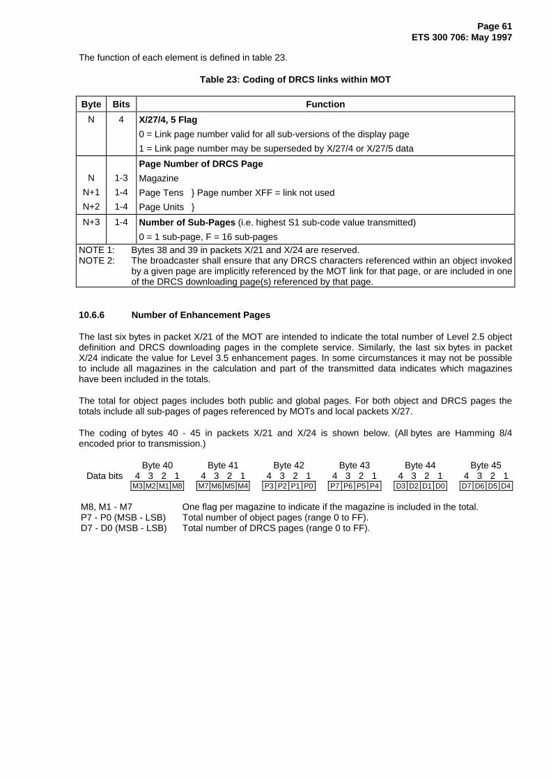
Page 61ETS 300 706: May 1997
The function of each element is defined in table 23.
Table 23: Coding of DRCS links within MOT
Byte Bits Function
N 4 X/27/4, 5 Flag
0 = Link page number valid for all sub-versions of the display page
1 = Link page number may be superseded by X/27/4 or X/27/5 data
N
N+1
N+2
1-3
1-4
1-4
Page Number of DRCS Page
Magazine
Page Tens } Page number XFF = link not used
Page Units }
N+3 1-4 Number of Sub-Pages (i.e. highest S1 sub-code value transmitted)
0 = 1 sub-page, F = 16 sub-pagesNOTE 1: Bytes 38 and 39 in packets X/21 and X/24 are reserved.NOTE 2: The broadcaster shall ensure that any DRCS characters referenced within an object invoked
by a given page are implicitly referenced by the MOT link for that page, or are included in oneof the DRCS downloading page(s) referenced by that page.
10.6.6 Number of Enhancement Pages
The last six bytes in packet X/21 of the MOT are intended to indicate the total number of Level 2.5 objectdefinition and DRCS downloading pages in the complete service. Similarly, the last six bytes in packetX/24 indicate the value for Level 3.5 enhancement pages. In some circumstances it may not be possibleto include all magazines in the calculation and part of the transmitted data indicates which magazineshave been included in the totals.
The total for object pages includes both public and global pages. For both object and DRCS pages thetotals include all sub-pages of pages referenced by MOTs and local packets X/27.
The coding of bytes 40 - 45 in packets X/21 and X/24 is shown below. (All bytes are Hamming 8/4encoded prior to transmission.)
Byte 40 Byte 41 Byte 42 Byte 43 Byte 44 Byte 45Data bits 4 3 2 1 4 3 2 1 4 3 2 1 4 3 2 1 4 3 2 1 4 3 2 1
M3 M2 M1 M8 M7 M6 M5 M4 P3 P2 P1 P0 P7 P6 P5 P4 D3 D2 D1 D0 D7 D6 D5 D4
M8, M1 - M7 One flag per magazine to indicate if the magazine is included in the total.P7 - P0 (MSB - LSB) Total number of object pages (range 0 to FF).D7 - D0 (MSB - LSB) Total number of DRCS pages (range 0 to FF).

Page 62ETS 300 706: May 1997
10.7 Links between Enhanced System Components
10.7.1 Linking to Object and DRCS Pages via the MOT
The action of linking to object definition and DRCS downloading pages via the MOT is summarized infigure 21.
242322
212019
Packet 0
18
15
6
14
5
1
Page Header MOT
x00Decimal page
numbers
x01
x98 x99
xA0 xA1
xFF
Hex pagenumbers
Not used
GPOP POP1 POP2 POP3POP4 POP5 POP6 POP7
G 1 2 3 4 5 6 7 No.
GPOP POP1 POP2 POP3POP4 POP5 POP6 POP7
G 1 2 3 4 5 6 7 No.
Level2.5
POP links
DRCS links
Level3.5
POP links
DRCS links
xnn
GDRCS flag &DRCS link no.
GPOP flag &POP link no.
xFE
(G)DRCSPage No.
No. ofSub-pages
DRCS Page
(G)POPPage No.
No. ofSub-pages
Flags 1st DefaultObject
2nd DefaultObject
Object
Object Page
Object Pointers
Object Definitions
Figure 21: Linking to object and DRCS pages via the MOT
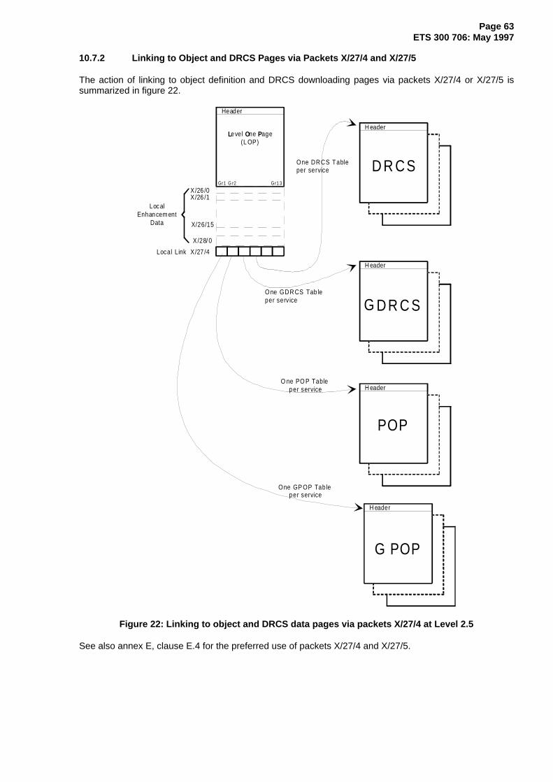
Page 63ETS 300 706: May 1997
10.7.2 Linking to Object and DRCS Pages via Packets X/27/4 and X/27/5
The action of linking to object definition and DRCS downloading pages via packets X/27/4 or X/27/5 issummarized in figure 22.
H eader
X/26 /1
X/26/15
Gr1 G r2 G r1 3
Header
X/26 /0
LocalEnhancem ent
Data
Level One Page(L OP)
X/28/ 0
X/27 /4Local Link
H eader
H eader
H eader
POP
G POP
G
D R CS
D R C S
O ne PO P Table per service
One GP OP Tab le per service
O ne GDR CS Tab leper service
One DRCS Tableper service
Figure 22: Linking to object and DRCS data pages via packets X/27/4 at Level 2.5
See also annex E, clause E.4 for the preferred use of packets X/27/4 and X/27/5.

Page 64ETS 300 706: May 1997
In the above example the four links have the following functions at Level 2.5:
Link 1: Global POP;Link 2: Normal POP;Link 3: Global DRCS;Link 4: Normal DRCS.
At Level 3.5 the last two links of the packet X/27/4 and the first two links of a packet X/27/5 might be used.
11 System Components for Navigation
This clause defines system components which suitable decoders can interpret to assist the user in findinginformation and navigating within a Teletext database.
11.1 Navigation via FLOF
11.1.1 Principles
The FLOF Code of Practice (annex H) defines a user-friendly page access method. The user is presentedwith a number of choices regarding pages to read next and selects one with a single key press on hiscontrol unit. Page access times can be significantly reduced if the decoder has additional page storagecapacity.
11.1.2 Additional components
In addition to the normal page packets Y = 0 to Y = 23, the service features require the use of packetsY = 24, Y= 27/0 and optionally packet 8/30 Format 1.
- Packets Y = 24. In this application, this packet contains user "prompt" information for display,provided by the page editor. It associates a given key on the user's control unit with a linked pageaddress included in packets with Y = 27.
Packets Y = 27, designation code value 0000. This packet contains the addresses of linked pagesto be associated with the user "prompt" information carried in the packet with Y = 24, link controlinformation, a display row 24 flag and error detection data (see subclause 9.6.1).
- Packet 8/30 Format 1 - Broadcast Service Data (see subclause 9.8.1). When there is no valid dataavailable for a given category of the information carried by this packet, fall-back codes should beincluded.

Page 65ETS 300 706: May 1997
Navigation via FLOF is summarized in figure 23.
H eaderLevel 1 Page
X/27/0
X /1
X/23X/24
X/23X/2 4X/27/0
title2t it le1 title3 t it le4
page apag e b
page cpage d
p ag e f
a b c d f
tit le1t it le2
tit le3tit le4
Ind ex Pag e
U p to 4 x co loured key words with variab le lengthU p to 6 pag e num bers for ed ito ria l links
Figure 23: Principles of navigation via FLOF
11.2 Navigation via TOP
11.2.1 Principles
The TOP Code of Practice (see annex I) defines a user-friendly page access method. The basic ideaunderlying the TOP system is to categorize the pages within a Teletext transmission according to specificthemes and sub-themes. This information, comprising titles and page numbers, is transmitted via anumber of special pages. The decoder can build menus for the user from this data, allowing the user toselect a page by theme or content. Page access times can be significantly reduced if the decoder hasadditional page storage capacity.

Page 66ETS 300 706: May 1997
11.2.2 Additional components
There are four types of data pages used within TOP. Each comprises packets in the range Y = 0 to Y = 23only, although an optional packet with Y = 28/0 (Format 1) may be included to define the page functionand coding (see subclause 9.4.2.4):
- Basic TOP table (BTT). Packets with Y = 1 to Y = 23 are coded Hamming 8/4 throughout. The pagenumber is fixed at 1F0.
- Additional Information Table (AIT). Each packet in the range Y = 1 to Y = 23 has bytes 6 to 13 and26 to 33 coded Hamming 8/4, and bytes 14 to 25 and 34 to 45 coded 7 bits data plus 1 oddparity bit. The page number is defined from within the BTT data.
- Multi-Page Tables (MPT). Packets with Y = 1 to Y = 23 are coded Hamming 8/4 throughout. Thepage number is defined from within the BTT data.
- Multi-Page Extension Table (MPT-EX). Packets with Y = 1 to Y = 23 are coded Hamming 8/4throughout. The page number is defined from within the BTT data.
Navigation via TOP is summarized in figure 24.
H eader
100101102
899
}
Basic Top Table (BTT)
Additional InformationTables (AIT)
Multipage Table (MPT)
Multipage Extens ion Table (MPT-EX)
Title2Title1Title4Title3
Title44Title43
Header
100101102
899
Header
HeaderH eader
Header
BTT-Lis t100101
22
21
1
22
210
11
20
20
1
2223
Page L inkingTable
Page Properties
Figure 24: Principles of navigation via TOP tables
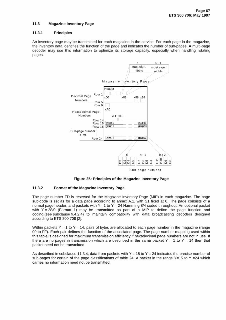
Page 67ETS 300 706: May 1997
11.3 Magazine Inventory Page
11.3.1 Principles
An inventory page may be transmitted for each magazine in the service. For each page in the magazine,the inventory data identifies the function of the page and indicates the number of sub-pages. A multi-pagedecoder may use this information to optimize its storage capacity, especially when handling rotatingpages.
Header
x03 x98 x99x00Decimal PageNumbers
xA0
xFFxFE
M a g a z in e In v e n to ry P a g e
least sign.nibble
most sign.nibble
Row 24
Row 1
Row 5Row 6
Hexadecimal PageNumbers
Row 14Row 15Row 16
Sub-page number> 79
n + 1n n + 2
S u b p a g e n u m b e r
n n + 1
group 1
group 1group 1
group 13group 13
group 13
D3
D2
D1
D0
D7
D6
D5
D4
D11
D10
D9
D8
Figure 25: Principles of the Magazine Inventory Page
11.3.2 Format of the Magazine Inventory Page
The page number FD is reserved for the Magazine Inventory Page (MIP) in each magazine. The pagesub-code is set as for a data page according to annex A.1, with S1 fixed at 0. The page consists of anormal page header, and packets with Y= 1 to Y = 24 Hamming 8/4 coded throughout. An optional packetwith Y = 28/0 (Format 1) may be transmitted as part of a MIP to define the page function andcoding (see subclause 9.4.2.4) to maintain compatibility with data broadcasting decoders designedaccording to ETS 300 708 [2].
Within packets Y = 1 to Y = 14, pairs of bytes are allocated to each page number in the magazine (range00 to FF). Each pair defines the function of the associated page. The page number mapping used withinthis table is designed for maximum transmission efficiency if hexadecimal page numbers are not in use. Ifthere are no pages in transmission which are described in the same packet Y = 1 to Y = 14 then thatpacket need not be transmitted.
As described in subclause 11.3.4, data from packets with Y = 15 to Y = 24 indicates the precise number ofsub-pages for certain of the page classifications of table 24. A packet in the range Y=15 to Y =24 whichcarries no information need not be transmitted.

Page 68ETS 300 706: May 1997
The construction of the MIP is shown in figure 26.
X/0 Page Header xFDX/1 x00 x01 x02 x03 x04 x05 x06 x07 x08 x09 x10 x11 x12 x13 x14 x15 x16 x17 x18 x19
X/2 x20 x21 x22 x23 x24 x25 x26 x27 x28 x29 x30 x31 x32 x33 x34 x35 x36 x37 x38 x39
X/3 x40 x41 x42 x43 x44 x45 x46 x47 x48 x49 x50 x51 x52 x53 x54 x55 x56 x57 x58 x59
X/4 x60 x61 x62 x63 x64 x65 x66 x67 x68 x69 x70 x71 x72 x73 x74 x75 x76 x77 x78 x79
X/5 x80 x81 x82 x83 x84 x85 x86 x87 x88 x89 x90 x91 x92 x93 x94 x95 x96 x97 x98 x99
X/6 xA0 xA1 xA2 xA3 xA4 xA5 xA6 xA7 xA8 xA9 xB0 xB1 xB2 xB3 xB4 xB5 xB6 xB7 xB8 xB9
X/7 xC0 xC1 xC2 xC3 xC4 xC5 xC6 xC7 xC8 xC9 xD0 xD1 xD2 xD3 xD4 xD5 xD6 xD7 xD8 xD9
X/8 xE0 xE1 xE2 xE3 xE4 xE5 xE6 xE7 xE8 xE9 xF0 xF1 xF2 xF3 xF4 xF5 xF6 xF7 xF8 xF9
X/9 x0A x0B x0C x0D x0E x0F x1A x1B x1C x1D x1E x1F x2A x2B x2C x2D x2E x2F
X/10 x3A x3B x3C x3D x3E x3F x4A x4B x4C x4D x4E x4F x5A x5B x5C x5D x5E x5F
X/11 x6A x6B x6C x6D x6E x6F x7A x7B x7C x7D x7E x7F x8A x8B x8C x8D x8E x8F
X/12 x9A x9B x9C x9D x9E x9F xAA xAB xAC xAD xAE xAF xBA xBB xBC xBD xBE xBF
X/13 xCA xCB xCC xCD xCE xCF xDA xDB xDC xDD xDE xDF xEA xEB xEC xED xEE xEF
X/14 xFA xFB xFC xFD xFE xFF
X/15 Subp 1 Subp 2 Subp 3 Subp 4 Subp 5 Subp 6 Subp 7 Subp 8 Subp 9 Subp 10 Subp 11 Subp 12 Subp 13
X/16 Subp 1 Subp 2 Subp 3 Subp 4 Subp 5 Subp 6 Subp 7 Subp 8 Subp 9 Subp 10 Subp 11 Subp 12 Subp 13
X/17 Subp 1 Subp 2 Subp 3 Subp 4 Subp 5 Subp 6 Subp 7 Subp 8 Subp 9 Subp 10 Subp 11 Subp 12 Subp 13
X/18 Subp 1 Subp 2 Subp 3 Subp 4 Subp 5 Subp 6 Subp 7 Subp 8 Subp 9 Subp 10 Subp 11 Subp 12 Subp 13
X/19 Subp 1 Subp 2 Subp 3 Subp 4 Subp 5 Subp 6 Subp 7 Subp 8 Subp 9 Subp 10 Subp 11 Subp 12 Subp 13
X/20 Subp 1 Subp 2 Subp 3 Subp 4 Subp 5 Subp 6 Subp 7 Subp 8 Subp 9 Subp 10 Subp 11 Subp 12 Subp 13
X/21 Subp 1 Subp 2 Subp 3 Subp 4 Subp 5 Subp 6 Subp 7 Subp 8 Subp 9 Subp 10 Subp 11 Subp 12 Subp 13
X/22 Subp 1 Subp 2 Subp 3 Subp 4 Subp 5 Subp 6 Subp 7 Subp 8 Subp 9 Subp 10 Subp 11 Subp 12 Subp 13
X/23 Subp 1 Subp 2 Subp 3 Subp 4 Subp 5 Subp 6 Subp 7 Subp 8 Subp 9 Subp 10 Subp 11 Subp 12 Subp 13
X/24 Subp 1 Subp 2 Subp 3 Subp 4 Subp 5 Subp 6 Subp 7 Subp 8 Subp 9 Subp 10 Subp 11 Subp 12 Subp 13
X/28/0Forma
t 1
Page function and coding, optional. (see subclause 9.4.2.4)
NOTE: Shaded bytes are not used.
Figure 26: Magazine Inventory Page
11.3.3 Page Function Coding
The pair of Hamming 8/4 coded bytes per page number yield an 8-bit page code value. The first byteprovides the lower nibble and the second the upper nibble.
second byte first byte4 3 2 1 4 3 2 1
MSB D7 D6 D5 D4 D3 D2 D1 D0 LSB< ------------------ Page Code ----------------->

Page 69ETS 300 706: May 1997
The interpretation to be placed on the Page Code values is shown in table 24.
Table 24: Magazine Inventory Page (MIP) Codes
PageCode
Function Notes
00 Page not in transmission01 Single normal page (note 1)
02 - 4F Normal pageSub-pages in range 2 to 79
A value in this range indicates the number ofsub-pages being transmitted. The number ofsub-pages is NOT defined in packets withY = 15 to Y = 24.
50 Normal page, multi-page setSub-pages in the range 80 to 212-1
Number of sub-pages defined according tosubclause 11.3.4.
51 Normal page, multi-page setSub-pages in the range 212 to 213-2
Number of sub-pages defined according tosubclause 11.3.4.
52 - 6F Reserved70 - 77 Subtitle page Maximum of one page of storage required.
The 3 LSBs correspond to the setting of theC12, C13 and C14 bits in the page headerof the subtitle page.
78 Subtitle Menu Page Maximum of one page of storage required.(note 2).
79 Page not following normal sub-code rules E.g. Alarm clock page. Maximum of onepage of storage required.
7A TV programme related warning page Maximum of one page of storage required.(note 3)
7B Current TV Programme information,multi-page set
Number of sub-pages defined according tosubclause 11.3.4, range 2 to 212-1.
7C Current TV Programme information,single page
Maximum of one page of storage required
7D "Now and Next" TV Programmes Maximum of one page of storage required.(note 5)
7E Index page to TV-related pages, multi-pageset
Number of sub-pages defined according tosubclause 11.3.4, range 2 to 212-1.
7F Index page to TV-related pages, single page Maximum of one page of storage required.80 Page transmitted but NOT part of the public
service(note 6)
81 Single Page containing TV scheduleinformation
(note1)
82 - CF TV schedule pages, multi-page setSub-pages in the range 2 to 79
A value in this range indicates the number ofsub-pages being transmitted. The number ofsub-pages is NOT defined in packets withY = 15 to Y = 24.
D0 TV schedule pages, multi-page setSub-pages in the range 80 to 212-1
Number of sub-pages defined according tosubclause 11.3.4.
D1 TV schedule pages, multi-page setSub-pages in the range 212 to 213-2
Number of sub-pages defined according tosubclause 11.3.4.
D2 - DF ReservedE0 Page Format - CA - data broadcasting page
Sub-pages in the range 1 to 212-1(note 7) Page defined according toETS 300 708 [2] clause 5.Number of sub-pages defined according tosubclause 11.3.4.
E1 Page Format - CA - data broadcasting pageSub-pages in the range 212 to 213-2
(note 7) Page defined according toETS 300 708 [2] clause 5.Number of sub-pages defined according tosubclause 11.3.4.
(continued)

Page 70ETS 300 706: May 1997
Table 24 (continued): Magazine Inventory Page (MIP) Codes
PageCode
Function Notes
E2 Page Format - CA - data broadcasting pageNumber of sub-pages not defined in packetswith Y = 15 to Y = 24
(note 7) Page defined according toETS 300 708 [2] clause 5.
E3 Page Format - Clear data broadcasting pageincluding EPG data
Page defined according to ETS 300 708 [2]clause 4. EPG data defined according toETS 300 707 [3]. Note 7.
E4 Page Format - Clear data broadcasting pagebut not carrying EPG data
Defined according to ETS 300 708 [2]clause 4.(note 7)
E5 DRCS page (use not defined)E6 Object page (use not defined)E7 Systems page without displayable element.
Function defined by page number.e.g.: MOT and MIP.
E8 DRCS page referenced in the MOT for thismagazine
(note 8)
E9 DRCS page referenced in the MOT for thismagazine but not required by a page in thismagazine
(note 8)
EA DRCS page referenced in the MOT for adifferent magazine but not required by a pagein this magazine
(note 8)
EB DRCS page not referenced in the MOT for adifferent magazine and required by a page inanother magazine
(note 8)
EC Object page referenced in the MOT for thismagazine
(note 8)
ED Object page referenced in the MOT for thismagazine but not required by a page in thismagazine
(note 8)
EE Object page referenced in the MOT for adifferent magazine but not required by a pagein this magazine
(note 8)
EF Object page not referenced in the MOT for adifferent magazine and required by a page inanother magazine
(note 8)
F0 - F3 Systems Pages for Broadcasters use(downstream processing)
F4 - F6 Engineering Test pages Test or operational information.F7 Systems page with displayable element.
Function defined by page number.F8 Keyword Search list page, multi-page set For use with packet X/25.
Number of sub-pages defined according tosubclause 11.3.4, range 2 to 212-1.
F9 Keyword Search list page, single page Maximum of one page of storage required.For use with packet X/25.
(continued)

Page 71ETS 300 706: May 1997
Table 24 (concluded): Magazine Inventory Page (MIP) Codes
PageCode
Function Notes
FA - FC ReservedFD Automatic Channel Installation (ACI) Annex L.FE TOP page (BTT, AIT, MPT or MPT-EX) (note 9)FF Reserved
NOTE 1: Decoders should treat this page as a single page storing only the last transmitted version.The contents of the page may change under editorial control. Any sub-pages should bedisplayed automatically when the page is selected for display.
NOTE 2: The Subtitle Menu Page is an editorial page indicating the pages numbers used forsubtitles in a number of different languages.
NOTE 3: This page contains information concerning the content of the current TV programme sothat the viewer can be warned of its suitability for general viewing. A decoder may choseto display this page automatically on a channel change or when it appears in thetransmission.
NOTE 4: A decoder may display this page on request from the viewer while the receiver isoperating in TV mode.
NOTE 5: This page may be displayed as a default in the absence of any Electronic ProgrammeGuide data (see ETS 300 707 [3]).
NOTE 6: This page could be designated editorially as being part of a premium or closed usergroup service that is not data broadcasting.
NOTE 7: Page not intended for display containing data for subsequent processing, e.g.telesoftware.
NOTE 8: The decoder can use this information to aid determination of the priority of storing aparticular DRCS or object definition page.
NOTE 9: This code applies to all TOP related pages. The decoder should interpret the functionaccording to the principles outlined in annex I.
11.3.4 Sub-page range
Certain page codes in table 24 indicate that the page comprises a number of sub-pages. The precisenumber of sub-pages is coded into packets with Y = 15 to Y = 24. Groups of three bytes (coded Hamming8/4) provide the 12 LSBs to define values up to 212-1, the bits being transmitted least significant bit first.For a sub-set of these page codes, values up to 213-2 can be identified and the least significant bit of thepage code provides the most significant bit of the number of sub-pages.
LSB of Page Code,where applicable
third byteof group
second byteof group
first byteof group
1 4 3 2 1 4 3 2 1 4 3 2 1MSB D12 D11 D10 D9 D8 D7 D6 D5 D4 D3 D2 D1 D0 LSB
<------------------------------------- Number of sub-pages --------------------------------------- --------->
The three byte groups within packets with Y = 15 to Y = 24 are arranged in the order of occurrence of thepage codes which support sub-page definition in packets with Y = 1 to Y = 14. In any packet, byte 6 is notused and the first group starts at byte 7.
12 Presentation Levels
This clause defines four Presentation Levels with reference to the transmission requirements, the displayfeatures available at each Level and the response of a suitable decoder. To maintain compatibility with alldecoder types, especially all existing decoders, a display at a higher Presentation Level is achieved bysending additional data to enhance a basic Teletext page.
Presentation Level 1: defines the basic Teletext page, characterised by the use of spacing attributesonly and a limited alphanumeric and mosaics repertoire.
Presentation Level 1.5: decoder responds as Level 1 but the character repertoire is extended viapackets X/26.

Page 72ETS 300 706: May 1997
Presentation Level 2.5: extends the fixed alphanumeric and mosaic repertoire and increases thenumber of display colours. Sixteen of the 32 colours are re-definable. Thenumber of character spaces per row can be increased to 56, providing sidepanels of 16 characters. It introduces non-spacing display attributes and alimited number of redefinable characters.
Presentation Level 3.5: extends the number of redefinable characters and the modes available andintroduces bolding, italicising, and proportional spacing of alphanumericcharacters. All 32 colours are redefinable.
12.1 Display Components
Table 25 summarizes the main display components and their availability at each presentation Level.
Table 25: Summary of Display Components and their application
DisplayComponent
DescriptionPresentation
Level 1 1.5 2.5 3.5
DisplayRows andColumns
Up to 24 rows, (plus an optional 25th row for navigation purposes),transmitted in packets X/0 to X/24, top to bottom of a page in magazine X.
40 character spaces (columns) in rows 1 to 24, transmitted from left toright.
Following the 8 control codes (which should not be displayed), 32character-spaces in the header (row 0), transmitted from left to right.
NOTE: It is usual practice to transmit "time-of-day" information in thelast 8 character spaces of packet X/0.
~ ~ ~ ~
An additional 16 character spaces can be displayed as side-panels inrows 1 - 24. The display data is defined via packets X/26 and Objects.
NOTE: No side-panel information is transmitted for row 0. If side-panels are used with the page, the display format of row 0 isat the discretion of the equipment manufacturer.
{ { ~ ~
CharacterBytes
In packets X/0 to X/25, each data byte (coded 7 bits plus odd parity)selects an alphanumeric character from a G0 character set, a mosaiccharacter from the G1 character set or a spacing attribute to occupy acharacter-space.
~ ~ ~ ~
In countries where Level 1 decoders exist, a suitable fall back charactershould be transmitted in character locations to be overwritten by data frompackets X/26. In countries where there are no Level 1 decoders, an evenparity character may be transmitted in these character locations.
{ ~ ~ ~
(continued)

Page 73ETS 300 706: May 1997
Table 25 (continued): Summary of Display Components and their application
DisplayComponent
DescriptionPresentation
Level 1 1.5 2.5 3.5
G0Character
Set
Set of 95 alphanumeric characters, plus SPACE (2/0), used as the defaultcharacter set. Address range 2/0 to 7/F. The Latin G0 set, table 35, is thedefault set.
National option characters exist for certain locations in some G0 sets.Where the decoder is capable of displaying more than one national optionsub-set, the correct character to display is determined from control bitsC12 - C14. Note that this substitution of certain characters only occurswhen a G0 set character is referenced from packets X/1-X/25 of theLevel 1 page. It does not apply when characters are referenced viapackets X/26 or objects.
In some countries two G0 sets are required to meet the languagerequirements. The spacing attribute ESC (code 1/B) is used to switchbetween the two alternative character sets. The default G0 set to be usedat the start of each display row is determined from the C12 - C14control bits. Each occurrence of ESC within the display row causes thedecoder to toggle between the two sets.
~ ~ ~ ~
G0Character
SetDesignation
and Re-designation
Optionally, one G0 character set can be designated by packets X/28/1and/or M/29/1 for compatibility with earlier specifications. The page-relateddata (X/28/1) takes precedence over the magazine-related data (M/29/1).Decoders may respond to this data to ensure the correct interpretation ofthe C12, C13 and C14 control bits when selecting national option setsrelated to the designated or default G0 character set. Equipment intendedfor operation with only a single group of character set options may ignorethis data.
{ ~ { {
Optionally, the two G0 character sets and additional data regarding thecorrect selection of national option subsets can be designated by packetsX/28/0 Format 1 and M/29/0. The page-related data (X/28/0 Format 1)takes precedence over the magazine-related data (M/29/0). Equipmentintended for operation with only a single group of character set optionsmay ignore this data.
{ ~ ~ ~
Optionally, the G0 set accessible via packets X/26 or objects can bere-designated by a column address group triplet.
{ { ~ ~
Optionally, the two G0 character sets and additional data regarding thecorrect selection of national option subsets can be designated by packetsX/28/4 and M/29/4. The page-related data (X/28/4) takes precedence overthe magazine-related data (M/29/4). Equipment intended for operationwith only a single group of character set options may ignore this data.
{ { { ~
G1Character
Set
Fixed set of 63 block mosaic characters plus SPACE (2/0) and 32alphanumeric characters, table 47. Address range 2/0 to 7/F. The mosaiccharacters are displayed with their elements either contiguous orseparated, (see subclause 15.7.1). The alphanumeric characters atpositions 4/0 to 5/F are taken from the G0 set, applying the same rules tonational option positions as described above.
~ ~ ~ ~
(continued)

Page 74ETS 300 706: May 1997
Table 25 (continued): Summary of Display Components and their application
DisplayComponent
DescriptionPresentation
Level 1 1.5 2.5 3.5
G2 Supple-mentary
CharacterSet
Set of 95 supplementary alphanumeric characters plus SPACE (2/0).Address range 2/0 to 7/F. The Latin G2 supplementary character set,table 37, is the default. The response of a decoder to codes 5/9, 5/A, 5/Band 6/5 is not defined.
NOTE: The repertoire of these additional characters available in aLevel 1.5 decoder is not fixed and is determined by thelanguage requirements in the country of use.
{ ~ ~ ~
G2 Supple-mentary
Character
Optionally, the G2 character can be designated by packets X/28/0Format 1 and M/29/0. The page-related data (X/28/0 Format 1) takesprecedence over the magazine-related data (M/29/0).
{ { ~ ~
SetDesignation
Optionally, the G2 set accessible via packets X/26 or objects can be re-designated by a column address triplet.
{ { ~ ~
and Re-designation
Optionally, the G2 character can be designated by packets X/28/4 andM/29/4. The page-related data (X/28/4) takes precedence over themagazine-related data (M/29/4).
{ { { ~
G3Character
Set
Fixed set of 95 smoothed block mosaic and line drawing characterscomprising 91 symbols plus SPACE (5/F), table 48. Address range 2/0 to7/F. The response of a decoder to codes 6/E, 6/F, 7/E and 7/E is notdefined.
{ ~ ~ ~
Bold, Italics,Prop. spacing
The G0 and G2 character sets may be displayed in bold, in italics orproportionally spaced, (see subclause 12.3.4).
{ { { ~
Redefinable
Characters(DRCS)
24 DRCS characters of mode type 12x10x1, displayed using theforeground and background colours selected at the display position.
Pixel patterns defined via DRCS downloading pages whose pagenumbers are specified in the Magazine Organization Table (MOT) and/orpackets X/27/4 or X/27/5 (see subclauses 10.6 and 9.6.2 respectively).Each character is defined by one Pattern Transfer Unit (PTU) of 20 bytes.
{ { ~ {
Four different DRCS modes are available:
12x10x1 Pixel colour = foreground colour at the display position. OnePTU per character.
12x10x2 Pixel colours = up to 4 colours from the Colour Map; the setof colours is defined using a DCLUT4. Two PTUs percharacter.
12x10x4 Pixel colours = up to 16 colours from the Colour Map; the setof colours is defined using a DCLUT16. Four PTUs percharacter.
6x5x4 Pixel colours = up to 16 colours from the Colour Map; the setof colours is defined using a DCLUT16. One PTU percharacter.
A Level 3.5 decoder should have the memory capacity to display up to384 PTUs.
The page numbers and number of sub-tables used for the downloadingprocess are specified in the Magazine Organization Table and/or inpackets X/27/4 and X/27/5.
Packets X/28/3 are associated with DRCS downloading pages to definethe mode of each DRCS character.
{ { { ~
(continued)

Page 75ETS 300 706: May 1997
Table 25 (continued): Summary of Display Components and their application
DisplayComponent
DescriptionPresentation
Level 1 1.5 2.5 3.5
Objects Objects as described in clause 13. An Object may comprise any collectionof characters, mosaics or non-spacing attributes available at Levels 2.5.and 3.5. Objects may be displayed in both the page and side-panel areas.An Object may not be positioned so that it crosses the boundary betweenpage and side-panel areas.
{ { ~ ~
CharacterColours
8 background full intensity colours: Black, Red, Green, Yellow, Blue,Magenta, Cyan, White.
7 foreground full intensity colours: Red, Green, Yellow, Blue, Magenta,Cyan, White.
Invoked as spacing attributes via codes in packets X/0 to X/25.
~ ~ ~ ~
Black foreground: Invoked as a spacing attribute via codes in packets X/0to X/25.
{ { ~ ~
32 colours per page. The Colour Map contains four CLUTs(numbered 0 - 3), each of 8 entries. Each entry has a four bit resolution forthe RGB components, subclause 12.4.
Colour Definition
CLUT 0 defaults to the full intensity colours used as spacing colourattributes at Levels 1 and 1.5.
CLUT 1, entry 0 is defined to be transparent. CLUT 1, entries 1 to 7 defaultto half intensity versions of CLUT 0, entries 1 to 7.
CLUTs 2 and 3 have the default values specified in subclause 12.4. CLUTs2 and 3 can be defined for a particular page by packet X/28/0 Format 1, orfor all pages in magazine M by packet M/29/0.
Colour Selection
CLUT 0, entries 1 to 7 are selectable directly by the Level 1 data asspacing attributes. CLUTs 0 to 3 are selectable via packets 26 or objectsas non-spacing attributes.
The foreground and background colour codes on the Level 1 page may beused to select colours from other parts of the Colour Map. Different CLUTsmay be selected for both foreground and background colours.This mapping information is transmitted in packet X/28/0 Format 1 for theassociated page and in packet M/29/0 for all pages in magazine M.
{ { ~ ~
With the exception of entry 0 in CLUT 1 (transparent), CLUTs 0 and 1 canbe redefined for a particular page by packet X/28/4, or for all pages inmagazine M by packet M/29/4.
{ { { ~
Row andScreenColours
Full row and full screen colours may be displayed. Any of the 32 coloursmay be selected. Selection is made explicitly via data in packets X/26 orobjects, or, as separate defaults for the screen area and all rows, from datain packets X/28/0 Format 1 (for the associated page) or packet M/29/0 (forall pages in magazine M). In the absence of any row or screen colourselection data, the default colour is Black (CLUT 0, entry 0 in the ColourMap). The colour selected also applies to the side-panel areas.
{ { ~ ~
Side-Panel(s)
Side-panels, as described in subclause 12.5, allow additional charactersper row. A total of 56 characters/symbols can be displayed on each row.The additional columns can appear to the left or right of the normal40 character row, in any combination.
{ { ~ ~

Page 76ETS 300 706: May 1997
12.2 Spacing attributes
Set of 32 spacing attributes, four without response at Levels 1 and 1.5, transmitted via packets X/0 toX/25. The decoder defaults to specified attributes at the start of each display row. Some attributes haveeffect immediately ("Set-At"), others at the following character-space ("Set-After"). The action of anattribute persists until the end of a row or until the transmission of a further attribute that modifies itsaction. Unless operating in "Hold Mosaics" mode, each character space occupied by a spacing attribute isdisplayed as a SPACE. The spacing attributes are summarized in table 26.
Table 26: Spacing attributes
Code(hex) Function
PresentationLevel
1 1.5 2.5 3.5
0/0
to
0/7
Alpha Colour Codes ("Set-After")
The alpha colour codes set the foreground colour of the characters to theappropriate colour and select a G0 set as the current default character set. Theseconditions persist until changed by a further colour code attribute (either alpha ormosaic), or the start of a new row.
0/0 Alpha Black ("Set-After")
NOTE: Alpha Black should be used with caution as it is interpreted by someexisting Level 1 and Level 1.5 decoders.
{ { ~ ~
0/1 Alpha Red ("Set-After") ~ ~ ~ ~
0/2 Alpha Green ("Set-After") ~ ~ ~ ~
0/3 Alpha Yellow ("Set-After") ~ ~ ~ ~
0/4 Alpha Blue ("Set-After") ~ ~ ~ ~
0/5 Alpha Magenta ("Set-After") ~ ~ ~ ~
0/6 Alpha Cyan ("Set-After") ~ ~ ~ ~
0/7 Alpha White ("Set-After") - Start-of-row default condition. ~ ~ ~ ~
0/8 Flash ("Set-After")
This code causes the foreground pixels of the following alphanumeric and mosaicscharacters to alternate between the foreground and background colours. The flashaction is cancelled by a Steady command (0/9) or by the start of a new row.
~ ~ ~ ~
0/9 Steady ("Set-At") - Start-of-row default condition.
This code cancels the flash action of code 0/8.
~ ~ ~ ~
0/A End Box ("Set-After") - Start-of-row default condition.
This code cancels the action of the Start Box code 0/B
~ ~ ~ ~
0/B Start Box ("Set-After")
On pages with the C5 or C6 bits set (Newsflash or subtitle), this code defines (oneach appropriate row) the start of an area that is to be boxed into the normal videopicture. Characters outside this area are not displayed, but changes in displaymode, colour, height etc., will affect the boxed area. Cancelled by an End Boxcode (0/A) or by the start of a new row.
NOTE: Protection against false operation is provided by double transmissionof Start Box control characters, with the action taking place betweenthem.
~ ~ ~ ~
(continued)
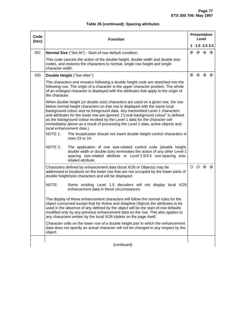
Page 77ETS 300 706: May 1997
Table 26 (continued): Spacing attributes
Code(hex) Function
PresentationLevel
1 1.5 2.5 3.5
0/C Normal Size ("Set-At") - Start-of-row default condition.
This code cancels the action of the double height, double width and double sizecodes, and restores the characters to normal, single row height and singlecharacter width.
~ ~ ~ ~
0/D Double Height ("Set-After")
The characters and mosaics following a double height code are stretched into thefollowing row. The origin of a character is the upper character position. The wholeof an enlarged character is displayed with the attributes that apply to the origin ofthe character.
When double height (or double size) characters are used on a given row, the rowbelow normal height characters on that row is displayed with the same localbackground colour and no foreground data. Any transmitted Level 1 charactersand attributes for the lower row are ignored. ("Local background colour" is definedas the background colour invoked by the Level 1 data for the character cellimmediately above as a result of processing the Level 1 data, active objects andlocal enhancement data.)
NOTE 1: The broadcaster should not insert double height control characters inrows 23 or 24.
NOTE 2: The application of one size-related control code (double height,double width or double size) terminates the action of any other Level 1spacing size-related attribute or Level 2.5/3.5 non-spacing size-related attribute.
~ ~ ~ ~
Characters defined by enhancement data (local X/26 or Objects) may beaddressed to locations on the lower row that are not occupied by the lower parts ofdouble height/size characters and will be displayed.
NOTE: Some existing Level 1.5 decoders will not display local X/26enhancement data in these circumstances.
The display of these enhancement characters will follow the normal rules for theobject concerned except that for Active and Adaptive Objects the attributes to beused in the absence of any defined by the object will be the start-of-row defaultsmodified only by any previous enhancement data on the row. This also applies toany characters written by the local X/26 triplets on the page itself.
Character cells on the lower row of a double height pair in which the enhancementdata does not specify an actual character will not be changed in any respect by theobject.
{ { ~ ~
(continued)

Page 78ETS 300 706: May 1997
Table 26 (continued): Spacing attributes
Code(hex) Function
PresentationLevel
1 1.5 2.5 3.5
0/E Double Width ("Set-After")
Characters are to be stretched horizontally to occupy the next character-space.
NOTE 4: Double Width should be used with caution as it is interpreted by someexisting Level 1 and Level 1.5 decoder. Since the attribute has a"Set-After" function, for correct display the broadcaster should nottransmit this attribute in column 38 of any display row nor immediatelypreceding the edge of a boxed area.
NOTE 5: The application of one size-related control code (double height,double width or double size) terminates the action of any other Level 1spacing size-related attribute or Level 2.5/3.5 non-spacing size-related attribute.
{ { ~ ~
0/F Double Size ("Set-After")
Characters are to be stretched horizontally and vertically as for both double heightand double width characters.
When double size characters are used on a given row, the row below normalheight characters on that row is displayed with the same local background colourand no foreground data. Any transmitted Level one characters and attributes forthe lower row are ignored. ("Local background colour" is defined as thebackground colour invoked by the Level 1 data for the character cell immediatelyabove as a result of processing the Level 1 data, active objects and localenhancement data.)
Characters defined by enhancement data (local X/26 or Objects) may beaddressed to locations on the lower row that are not occupied by the lower parts ofdouble height/size characters and will be displayed.
NOTE 6 : Some existing Level 1.5 decoders will not display local X/26enhancement data in these circumstances.
The display of these enhancement characters will follow the normal rules for theobject concerned except that for Active and Adaptive Objects the attributes to beused in the absence of any defined by the object will be the start-of-row defaultsmodified only by any previous enhancement data on the row. This also applies toany characters written by the local X/26 triplets on the page itself.
Character cells on the lower row of a double height pair in which the enhancementdata does not specify an actual character will not be changed in any respect by theobject.
NOTE 7: The broadcaster should not insert double height control characters inrows 23 or 24.
NOTE 8: The application of one size-related control code (double height,double width or double size) terminates the action of any other Level 1spacing size-related attribute or Level 2.5/3.5 non-spacing size-related attribute.
NOTE 9: Double Size should be used with caution as it is interpreted by someexisting Level 1 and Level 1.5 decoder. Some may interpreted it asDouble Height. Since the attribute has a "Set-After" function, forcorrect display this attribute should not be inserted in column 38 ofany display row nor immediately preceding the edge of a boxed area.
{ { ~ ~
(continued)

Page 79ETS 300 706: May 1997
Table 26 (continued): Spacing attributes
Code(hex) Function
PresentationLevel
1 1.5 2.5 3.5
1/0
to
1/7
Mosaic Colour Codes ("Set-After")
The mosaic colour codes set the foreground colour of the characters to theappropriate colour and select the G1 set as the current default character set.These conditions persist until changed by a further colour code attribute (eitheralpha or mosaic), or the start of a new row.
For subsequent characters in columns 2, 3, 6 & 7 of the G1 set, bits 1, 2, 3, 4, 5 &7 respectively set the top left, top right, middle left, middle right, lower left andlower right graphic blocks of each character.
1/0 Mosaics Black ("Set-After")
NOTE 10: Mosaics Black should be used with caution as it is interpreted bysome existing Level 1 and Level 1.5 decoders.
{ { ~ ~
1/1 Mosaics Red ("Set-After") ~ ~ ~ ~
1/2 Mosaics Green ("Set-After") ~ ~ ~ ~
1/3 Mosaics Yellow ("Set-After") ~ ~ ~ ~
1/4 Mosaics Blue ("Set-After") ~ ~ ~ ~
1/5 Mosaics Magenta ("Set-After") ~ ~ ~ ~
1/6 Mosaics Cyan ("Set-After") ~ ~ ~ ~
1/7 Mosaics White ("Set-After") ~ ~ ~ ~
1/8 Conceal ("Set-At")
The following characters up to the end of the row, or until a Colour Code attribute(codes 0/0 to 0/7 or 1/0 to 1/7) is encountered, are to be displayed as SPACESuntil revealed by a decoder or user operation.
~ ~ ~ ~
1/9 Contiguous Mosaic Graphics ("Set-At") - Start-of-row default condition
The blocks of a mosaics character adjoin one another.
NOTE 11: This code has effect only on characters defined at Levels 1 and 1.5.
~ ~ ~ ~
1/A Separated Mosaic Graphics ("Set-At")
Each block of a mosaics character is surrounded by a border of the backgroundcolour.
NOTE 12: This code has effect only on characters defined at Levels 1 and 1.5.
~ ~ ~ ~
1/B ESC (or Switch) ("Set-After")
Toggles between the first and second G0 sets defined by packets X/28/0 Format 1,X/28/4, M/29/0 or M/29/4. The default at the start of each row is the default G0 set.This does not affect characters written via packets X/26 or as part of an object.
NOTE 13: May also be used in connection with data for processing.
~ ~ ~ ~
1/C Black Background ("Set-At") - Start-of-row default condition.
This code immediately changes the background colour to the colour at entry 0 ofthe background CLUT, or to the current Full Row colour if black background coloursubstitution is in operation. The foreground colour is not affected.
~ ~ ~ ~
(continued)

Page 80ETS 300 706: May 1997
Table 26 (concluded): Spacing attributes
Code(hex) Function
PresentationLevel
1 1.5 2.5 3.5
1/D New Background ("Set-At")
This code causes a new background colour to be selected immediately.Any following characters and mosaics may be invisible until a different foregroundcolour attribute is encountered.
~ ~ ~ ~
The foreground colour currently selected is adopted as the background colour. ~ ~ { {
The CLUT from which the background colour is to be taken is defined by theColour Table Re-mapping bits in a packet X/28/0 Format 1, X/28/4, M/29/0 orM/29/4, if valid, otherwise defaulting to CLUT 0. The entry in the selected CLUT isspecified by the entry number of the foreground colour currently selected by theLevel 1 page.
{ { ~ ~
1/E Hold Mosaics ("Set-At")
Generally, all spacing attributes are displayed as spaces, implying at least onespace between characters or mosaics with different colours in the same row.In mosaics mode, the "Hold Mosaics" option allows a limited range of attributechanges without intervening spaces. A mosaic character from the G1 set (referredto as the "Held-Mosaic" character) is displayed in place of the character "SPACE"corresponding to a control character.
Substitution only takes place in mosaics mode when Hold Mosaics mode is inforce. At a screen location where substitution is permitted, the "Held-Mosaic"character inserted is the most recent mosaics character with bit 6 = '1' in its codeon that row. The "Held-Mosaic" character is reset to "SPACE" at the start of eachrow, on a change of alphanumeric/mosaics mode or on a change of size. It is notreset by reinforcement of the existing size setting. It is not reset by a change inHold Mosaics mode.
The "Held-Mosaic" character is always displayed in its original contiguous orseparated form regardless of the mode prevailing at the time of substitution.
NOTE 14: This code has effect only on characters defined at Levels 1 and 1.5.Size and character set changes invoked by enhancement triplets atLevels 2.5 and 3.5 do not cancel Hold Mosaics.
~ ~ ~ ~
1/F Release Mosaics ("Set-After") - Start-of-row default condition.
This code cancels the Hold Mosaics mode.
NOTE 15: This code has effect only on characters defined at Levels 1 and 1.5.
~ ~ ~ ~
12.3 Non-spacing attributes and additional characters
12.3.1 Use of Packets X/26
This subclause defines the function of the triplets of packets X/26. It is also applicable to packets X/3 toX/25 of an object definition page. In general, a triplet or combination of triplets define a screen locationand the enhancements to the Level 1 page to be set at that location. Certain enhancements also apply tosubsequent positions on the same row until either explicitly terminated or the end of the row is reached.The function of certain triplets may be modified depending on whether the triplet occurs in localenhancement data or within an object.

Page 81ETS 300 706: May 1997
The 18 data bits of each triplet are divided into 3 fields:
Address Mode Data6 5 4 3 2 1 11 10 9 8 7 18 17 16 15 14 13 12
A5 A4 A3 A2 A1 A0 M4 M3 M2 M1 M0 D6 D5 D4 D3 D2 D1 D0
Triplets are divided into two groups according to the value of the address field - a Column Address Group(0 ≤ Address ≤ 39) and a Row Address Group (40 ≤ Address ≤ 63).
The functions of the Row Address and Column Address triplets are summarized in table 27 and defined insubclauses 12.3.3 and 12.3.4 respectively.
Table 27: Summary of Packet X/26 Triplet Functions
ModeRow Address Group
(40 ≤ Address field ≤ 63)Column Address Group(0 ≤ Address field ≤ 39)
00000 Full Screen Colour Foreground Colour00001 Full Row Colour Block Mosaic Character from the G1 set00010 Reserved Line Drawing or Smoothed Mosaic
Character from the G3 set (Level 1.5)00011 Reserved Background Colour00100 Set Active Position Reserved00101 Reserved Reserved00110 Reserved PDC - Cursor Column & Announced Starting
& Finishing Time Minutes00111 Address Display Row 0 Additional Flash Functions01000 PDC - Country of Origin and Programme Source Modified G0 and G2 Character Set Design.01001 PDC - Month & Day Character from the G0 set (Levels 2.5 & 3.5)01010 PDC - Cursor Row & Announced Starting Time
HoursReserved
01011 PDC - Cursor Row & Announce Finishing TimeHours
Line Drawing or Smoothed MosaicCharacter from the G3 set (Levels 2.5 & 3.5)
01100 PDC - Cursor Row & Local Time Offset Display Attributes01101 PDC - Series Identifier and Series Code DRCS Character Invocation01110 Reserved Font Style01111 Reserved Character from the G2 set10000 Origin Modifier G0 character without diacritical mark10001 Active Object Invocation G0 character with diacritical mark10010 Adaptive Object Invocation G0 character with diacritical mark10011 Passive Object Invocation G0 character with diacritical mark10100 Reserved G0 character with diacritical mark10101 Active Object Definition G0 character with diacritical mark10110 Adaptive Object Definition G0 character with diacritical mark10111 Passive Object Definition G0 character with diacritical mark11000 DRCS Mode G0 character with diacritical mark11001 Reserved G0 character with diacritical mark11010 Reserved G0 character with diacritical mark11011 Reserved G0 character with diacritical mark11100 Reserved G0 character with diacritical mark11101 Reserved G0 character with diacritical mark11110 Reserved G0 character with diacritical mark11111 Termination Marker G0 character with diacritical mark

Page 82ETS 300 706: May 1997
12.3.2 Active Position
The address field of certain packet X/26 triplets is used to specify the Active Position. The Active Positionis defined by row and column co-ordinates and is a reference to a screen location within the normal pagearea. It is used to position enhancement data when overwriting a Level 1 page. The valid ranges are 0 to24 for the row component and 0 to 39 for the column component. The range is extended to the side-panelareas through the action of the Origin Modifier triplet.
Display row 0 is addressed by explicit use of the row address group with mode value 00111. This tripletalso has the action of setting both the row and column co-ordinates of the Active Position to 0.
A row co-ordinate in the range 1 to 24 is set by the address field of the most recent Full Row Colour or SetActive Position triplet. Address value 40 (decimal) implies row 24 and values 41 to 63 indicate rows 1 to23 inclusive. A Full Row Colour triplet also sets the column co-ordinate to 0. A Set Active Position tripletsets the column co-ordinate explicitly.
Level 2.5 and 3.5 decoders should not use the address field of other row address triplets for modifying theActive Position.
The Active Position is assumed to be reset to row 0, column 0 when starting to process localenhancement data or placing default objects.
Apart from the one column address triplet used for PDC and those which are reserved, the column co-ordinate is set by the address field of column address triplets and the row co-ordinate is not modified.
12.3.3 Row Address triplets
Table 28 defines the function of each Row Address triplet, i.e. triplets with address values � 40.
Table 28: Function of Row Address triplets
ModeBits
(M4...M1)
FunctionPresentation
Level
1 1.5 2.5 3.5
00000 Full Screen Colour { { ~ ~
Address (� 40) Mode Data6 5 4 3 2 1 11 10 9 8 7 18 17 16 15 14 13 12
R5 R4 R3 R2 R1 R0 0 0 0 0 0 S1 S0 C1 C0 E2 E1 E0
The address value does not alter the Active Position for object placement.
When S1 and S0 are both set to '0', the remaining data bits define the full screencolour. Bits C1 and C0 select a CLUT in the Colour Map of table 30, and bits E2- E0 select an entry from that CLUT. All other data field values are reserved.
Full screen colour applies to the screen area above row 0 and below row 23, orrow 24 if used. The default full screen colour to be used in the absence of thistriplet is defined in annex A.5.
The use of this function is restricted to local enhancement data and ActiveObjects.
(continued)
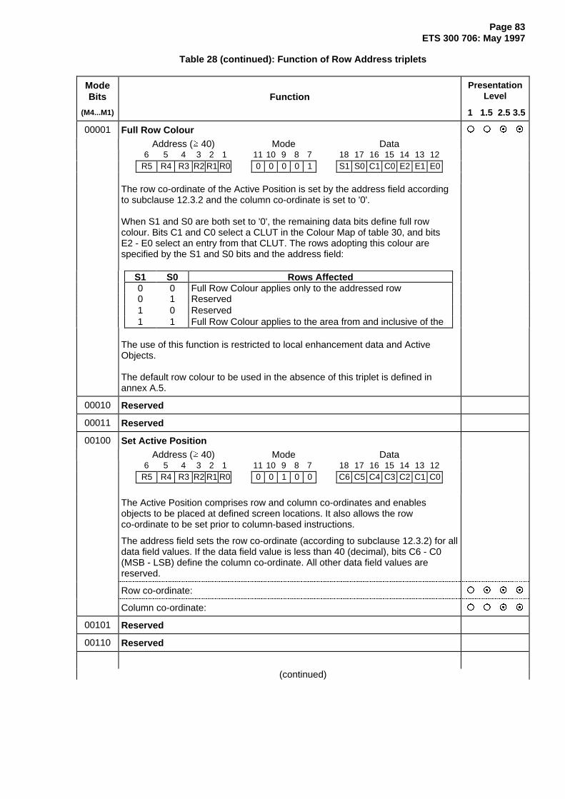
Page 83ETS 300 706: May 1997
Table 28 (continued): Function of Row Address triplets
ModeBits
(M4...M1)
FunctionPresentation
Level
1 1.5 2.5 3.5
00001 Full Row Colour { { ~ ~
Address (� 40) Mode Data6 5 4 3 2 1 11 10 9 8 7 18 17 16 15 14 13 12
R5 R4 R3 R2 R1 R0 0 0 0 0 1 S1 S0 C1 C0 E2 E1 E0
The row co-ordinate of the Active Position is set by the address field accordingto subclause 12.3.2 and the column co-ordinate is set to '0'.
When S1 and S0 are both set to '0', the remaining data bits define full rowcolour. Bits C1 and C0 select a CLUT in the Colour Map of table 30, and bitsE2 - E0 select an entry from that CLUT. The rows adopting this colour arespecified by the S1 and S0 bits and the address field:
S1 S0 Rows Affected0 0 Full Row Colour applies only to the addressed row0 1 Reserved1 0 Reserved1 1 Full Row Colour applies to the area from and inclusive of the
The use of this function is restricted to local enhancement data and ActiveObjects.
The default row colour to be used in the absence of this triplet is defined inannex A.5.
00010 Reserved
00011 Reserved
00100 Set Active PositionAddress (� 40) Mode Data
6 5 4 3 2 1 11 10 9 8 7 18 17 16 15 14 13 12R5 R4 R3 R2 R1 R0 0 0 1 0 0 C6 C5 C4 C3 C2 C1 C0
The Active Position comprises row and column co-ordinates and enablesobjects to be placed at defined screen locations. It also allows the rowco-ordinate to be set prior to column-based instructions.
The address field sets the row co-ordinate (according to subclause 12.3.2) for alldata field values. If the data field value is less than 40 (decimal), bits C6 - C0(MSB - LSB) define the column co-ordinate. All other data field values arereserved.
Row co-ordinate: { ~ ~ ~
Column co-ordinate: { { ~ ~
00101 Reserved
00110 Reserved
(continued)

Page 84ETS 300 706: May 1997
Table 28 (continued): Function of Row Address triplets
ModeBits
(M4...M1)
FunctionPresentation
Level
1 1.5 2.5 3.5
00111 Address Display Row 0 { ~ ~ ~
Address Mode Data6 5 4 3 2 1 11 10 9 8 7 18 17 16 15 14 13 121 1 1 1 1 1 0 0 1 1 1 S1 S0 C1 C0 E2 E1 E0
When the address field is set to 111111 the Active Position is set to row 0,column 0. Subsequent column address triplets should address columns 8 to 39only. The function of the triplet for other address values (40 - 62) is reserved andthe Active Position is not modified.
When row 0 is to be addressed and bits S1 and S0 are both set to '0', theremaining data bits define full row colour. Bits C1 and C0 select a CLUT in theColour Map of table 30, and bits E2 - E0 select an entry from that CLUT.The rows adopting this colour are specified by the S1 and S0 bits:
S1 S0 Rows Affected0 0 Full Row Colour applies to row 0 only0 1 Reserved1 0 Reserved1 1 Full Row Colour applies to the area from row 0 down to and
The default row colour to be used in the absence of this triplet is defined inannex A.5.
The use of this function is restricted to local enhancement data and ActiveObjects.
NOTE: The use of double height and double size attributes in row 0 is notpermitted.
01000 PDC Data - Country of Origin and Programme Source (see ETS 300 231 [1]) { ~ ~ ~
01001 PDC Data - Month and Day (see ETS 300 231 [1]) { ~ ~ ~
01010 PDC Data - Cursor Row and Announced Starting Time Hours(see ETS 300 231 [1])
{ ~ ~ ~
01011 PDC Data - Cursor Row and Announced Finishing Time Hours(see ETS 300 231 [1])
{ ~ ~ ~
01100 PDC Data - Cursor Row and Local Time Offset (see ETS 300 231 [1]) { ~ ~ ~
01101 PDC Data - Series Identifier and Series Code (see ETS 300 231 [1]) { ~ ~ ~
01110 Reserved
01111 Reserved
(continued)

Page 85ETS 300 706: May 1997
Table 28 (continued): Function of Row Address triplets
ModeBits
(M4...M1)
FunctionPresentation
Level
1 1.5 2.5 3.5
10000 Origin Modifier { { ~ ~
Address (� 40) Mode Data6 5 4 3 2 1 11 10 9 8 7 18 17 16 15 14 13 12
rR5 rR4 rR3 rR2 rR1 rR0 1 0 0 0 0 rC6 rC5 rC4 rC3 rC2 rC1 rC0
= Row Offset + 40 = Column Offset
The Origin Modifier changes the origin of the object whose invocation tripletimmediately follows it by adding temporary offset values to the row and columnco-ordinates of the current Active Position. After one object invocation bothoffsets are reset to '0' and the current Active Position is restored.
The row offset is calculated by subtracting 40 (decimal) from the address fieldvalue.
The column offset is defined by the data field. The valid range is 0 to 71(decimal), allowing access to the side-panels.
10001
10010
10011
Object InvocationThese three row address groups are used to invoke Active, Adaptive andPassive Objects respectively. The sequence of triplets defined in the object isexecuted at each invocation instance. The screen position of each element isdetermined from its individual co-ordinates, the Active position at the point ofinvocation and any Origin Modifier triplet immediately preceding the invocationtriplet.
General format of Object Invocation triplets:
{ { ~ ~
Address (� 40) Mode Data6 5 4 3 2 1 11 10 9 8 7 18 17 16 15 14 13 121 S1 S0 X N8 N7 1 0 0 M1M0 N6 N5 N4 N3 N2 N1 N0
Bit 3 is reserved. Bits 4 and 5 define the source of the object, and bits 7 and 8the object type:
S1 S0 Object Source M1 M0 Object Type(0 0 Illegal) (0 0 Origin Modifier)0 1 Local 0 1 Active1 0 POP 1 0 Adaptive1 1 GPOP 1 1 Passive
(continued)

Page 86ETS 300 706: May 1997
Table 28 (continued): Function of Row Address triplets
ModeBits
(M4...M1)
FunctionPresentation
Level
1 1.5 2.5 3.5
10001
10010
10011
(cont.)
Object Invocation (continued)
Bits N0 - N8 select a particular object of the specified type from the specifiedsource. The interpretation of these bits depends on whether a POP/GPOP orLocal Object is being invoked.
POP or GPOP Object
When the Object Source is indicated as POP or GPOP (S1 = 1, S0 = X), bits N0 to N8 identify the sub-page carrying the object definition and theposition of the associated pointer within the pointer table at the start of thepage:
Bits N3 - N0 (MSB - LSB) define the S1 component of the sub-code of thepage containing the object definition.
Bits N7 and N8 define the location of the relevant part of the PointerTable within the object page:
N8 N7 Pointer Location0 0 Packet 10 1 Packet 21 0 Packet 31 1 Packet 4
Bits N5 and N6 indicate the triplet containing the pointer data in the packetdefined by bits N7 and N8. The interpretation depends upon the type ofobject being invoked:
Triplet Number (range 0 - 12)N6 N5 Active Ada ptive Passive0 0 1 2 30 1 4 5 61 0 7 8 91 1 10 11 12
Bit N4 indicates the location of the pointer data within the triplet specifiedby bits N5 to N8:
N4 Pointer Position0 Bits 1 to 9 (LSB - MSB)1 Bits 10 to 18 (LSB - MSB)
Local Object
NOTE: A Local Object may only be invoked by local enhancement data.When the Object Source is indicated as Local (S1 = 0, S0 = 1), bit N8 is set to '0'. Bits N0 - N7 identify the location of the object'sdefinition triplet in terms of a packet 26 designation code and tripletnumber:
N7 - N4 (MSB - LSB) define the packet 26 designation code (range 0 - 15).N3 - N0 (MSB - LSB) define the triplet number (range 0 - 12).
(continued)

Page 87ETS 300 706: May 1997
Table 28 (continued): Function of Row Address triplets
ModeBits
(M4...M1)
FunctionPresentation
Level
1 1.5 2.5 3.5
10100 Reserved
10101
10110
10111
Object DefinitionThese three row address groups identify the start of Active, Adaptive andPassive Object definitions respectively. The following sequence of triplets isexecuted at each object invocation. An object is terminated by the next ObjectDefinition or Termination Marker triplet.
Format of Object Definition triplets:
{ { ~ ~
Address (� 40) Mode Data6 5 4 3 2 1 11 10 9 8 7 18 17 16 15 14 13 121 S1 S0 X N8 N7 1 0 1 M1M0 N6 N5 N4 N3 N2 N1 N0
Bit 3 is reserved. Bits 4 and 5 define the presentation Levels at which the objectis required, and bits 7 and 8 the object type:
S1 S0 Object Usage M1 M0 Object Type(0 0 Illegal) (0 0 Reserved)0 1 Level 2.5 0 1 Active1 0 Level 3.5 1 0 Adaptive1 1 Levels 2.5 and 3.5 1 1 Passive
Bits N0 - N8 are set to match the corresponding bits in any Object Invocationtriplet used to invoke this object:
Object definitions on POP or GPOP pages
N3 - N0 (MSB - LSB) are set to the same value as the S1 component of thesub-code of the page containing this object definition.
Bits N7 and N8 define the packet within this object page containing thepointer to this object:
N8 N7 Pointer Location0 0 Packet 10 1 Packet 21 0 Packet 31 1 Packet 4
Bits N5 and N6 indicate the triplet containing the pointer data in the packetdefined by bits N7 and N8. The interpretation depends upon the type ofobject being invoked:
Triplet Number (range 0 - 12)N6 N5 Active Ada ptive Passive0 0 1 2 30 1 4 5 61 0 7 8 91 1 10 11 12
(continued)

Page 88ETS 300 706: May 1997
Table 28 (continued): Function of Row Address triplets
ModeBits
(M4...M1)
FunctionPresentation
Level
1 1.5 2.5 3.5
1010110110
Bit N4 indicates the location of the pointer data within the triplet specifiedby bits N5 to N8:
10111 N4 Pointer Position(cont.) 0 Bits 1 to 9 (LSB - MSB)
1 Bits 10 to 18 (LSB - MSB)
Local Object Definitions
N8 is set to '0' and the remaining bits specify the location of the ObjectDefinition triplet:
N7 - N4 (MSB - LSB) define the packet 26 designation code (range 0 - 15).N3 - N0 (MSB - LSB) define the triplet number (range 0 - 12).
11000 DRCS ModeThe DRCS Mode triplet designates a DRCS sub-table and the validity of theDRCS data.
{ { ~ ~
Address (� 40) Mode Data6 5 4 3 2 1 11 10 9 8 7 18 17 16 15 14 13 12
R5 R4 R3 R2 R1 R0 1 1 0 0 0 S L1 L0 T3 T2 T1 T0
The address field is reserved and the Active Position is not modified.
The page numbers of normal and global DRCS pages are indicated in the MOTor via packets X/27/4 or X/27/5. Bit 18 defines whether a Global or a NormalDRCS sub-table page is being specified. Bits 16 and 17 define the presentationLevels at which the DRCS data will be used:
S Source Page L1 L0 DRCS Usage0 Global DRCS 0 0 Reserved1 Normal DRCS 0 1 Level 2.5
1 0 Level 3.51 1 Levels 2.5 and 3.5
Bits T3 - T0 (MSB-LSB) indicate the sub-table (sub-page) required. T3 - T0correspond to the S1 component of the sub-code.
The designated sub-table is assumed to be latched and used during subsequentDRCS character invocations. Where an object invokes a DRCS character, thesub-table designation shall be included within the definition of the same object.A normal and a global sub-table can be designated simultaneously.
NOTE: The scope of the DRCS mode information is restricted to the objector the local enhancement data in which it occurs. It is nottransferred to an invoked object or inherited on return.
11001to
11110Reserved
(continued)

Page 89ETS 300 706: May 1997
Table 28 (concluded): Function of Row Address triplets
ModeBits
(M4...M1)
FunctionPresentation
Level
1 1.5 2.5 3.5
11111 Termination MarkerAddress Mode Data
6 5 4 3 2 1 11 10 9 8 7 18 17 16 15 14 13 121 1 1 1 1 1 1 1 1 1 1 D6 D5 D4 D3 D2 D1 D0
Since more than one packet with Y = 26 may be needed to display a given page,a terminator is provided by setting the Address and Mode Description bits all to1, in the last triplet (bytes 43, 44 and 45) in the final packet in use. Any unuseddata groups between the active data groups and the termination group shall befilled with repetitions of the data in the termination group.
The data field bits are reserved. { ~ { {
At Levels 2.5 and 3.5, bits 12 - 14 in the data field identify the type of data beingterminated. Bits 15 -18 are reserved.
{ { ~ ~
D2 D1 D0 Function0 0 0 Intermediate (G)POP sub-page. End of object, more objects
follow on this page.0 0 1 Intermediate (G)POP sub-page. End of last object on this
page.0 1 0 Last (G)POP sub-page. End of object, more objects follow on
this page.0 1 1 Last (G)POP sub-page. End of last object on this page.1 0 0 Local Object definitions. End of object, more objects follow on
this page.1 0 1 Local Object definitions. End of last object on this page.1 1 0 Local enhancement data. End of enhancement data, Local
Object definitions follow.1 1 1 Local enhancement data. End of enhancement data, no Local
Object definitions follow.
The Termination Marker triplet may also be used as a "space-filler" betweenobject definitions and between the end of local enhancement data and the startof Local Object definitions.
12.3.4 Column Address triplets
A Column address triplet has the following format:
Address ≤ 39 Mode Data6 5 4 3 2 1 11 10 9 8 7 18 17 16 15 14 13 12
C5 C4 C3 C2 C1 C0 M4 M3 M2 M1 M0 D6 D5 D4 D3 D2 D1 D0
For all mode description values except all reserved values and the one used for PDC, the address fieldsets the column co-ordinate of the Active Position.
Table 29 defines the function of each Column Address triplet. The bits of the data field are numbered D0to D6.
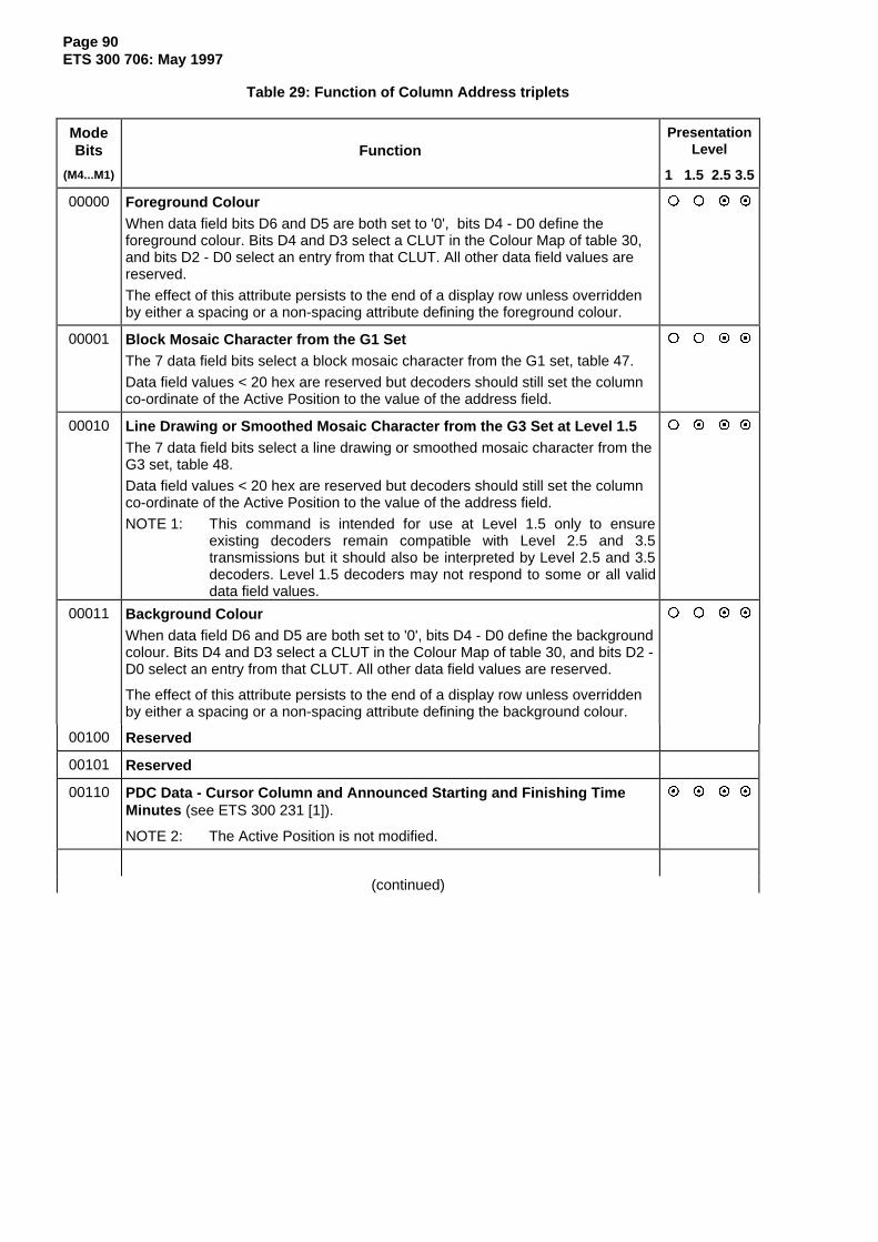
Page 90ETS 300 706: May 1997
Table 29: Function of Column Address triplets
ModeBits
(M4...M1)
FunctionPresentation
Level
1 1.5 2.5 3.5
00000 Foreground ColourWhen data field bits D6 and D5 are both set to '0', bits D4 - D0 define theforeground colour. Bits D4 and D3 select a CLUT in the Colour Map of table 30,and bits D2 - D0 select an entry from that CLUT. All other data field values arereserved.
The effect of this attribute persists to the end of a display row unless overriddenby either a spacing or a non-spacing attribute defining the foreground colour.
{ { ~ ~
00001 Block Mosaic Character from the G1 SetThe 7 data field bits select a block mosaic character from the G1 set, table 47.
Data field values < 20 hex are reserved but decoders should still set the columnco-ordinate of the Active Position to the value of the address field.
{ { ~ ~
00010 Line Drawing or Smoothed Mosaic Character from the G3 Set at Level 1.5The 7 data field bits select a line drawing or smoothed mosaic character from theG3 set, table 48.
Data field values < 20 hex are reserved but decoders should still set the columnco-ordinate of the Active Position to the value of the address field.
NOTE 1: This command is intended for use at Level 1.5 only to ensureexisting decoders remain compatible with Level 2.5 and 3.5transmissions but it should also be interpreted by Level 2.5 and 3.5decoders. Level 1.5 decoders may not respond to some or all validdata field values.
{ ~ ~ ~
00011 Background ColourWhen data field D6 and D5 are both set to '0', bits D4 - D0 define the backgroundcolour. Bits D4 and D3 select a CLUT in the Colour Map of table 30, and bits D2 -D0 select an entry from that CLUT. All other data field values are reserved.
The effect of this attribute persists to the end of a display row unless overriddenby either a spacing or a non-spacing attribute defining the background colour.
{ { ~ ~
00100 Reserved
00101 Reserved
00110 PDC Data - Cursor Column and Announced Starting and Finishing TimeMinutes (see ETS 300 231 [1]).
NOTE 2: The Active Position is not modified.
~ ~ ~ ~
(continued)

Page 91ETS 300 706: May 1997
Table 29 (continued): Function of Column Address triplets
ModeBits
(M4...M1)
FunctionPresentation
Level
1 1.5 2.5 3.5
00111 Additional Flash FunctionsThe flash functions affect the foreground colour only. For 12x10x2, 12x10x4 and6x5x4 DRCS characters, all the pixels are considered to be foreground pixels.
When data field bits D6 and D5 are both set to '0', bits D4 - D0 select a particularflash function. Bits D1 and D0 define the flash mode, and bits D4, D3 and D2 theflash rate and phase. Other data field values are reserved.
{ { ~ ~
D1 D0 Flash Mode0 0 Steady0 1 Normal flash to background colour1 0 Invert phase of flash to background colour1 1 Flash to the corresponding colour in an adjacent
D4 D3 D2 Flash Rate and Phase0 0 0 Slow rate (1Hz)0 0 1 Fast rate (2Hz), phase 10 1 0 Fast rate (2Hz), phase 20 1 1 Fast rate (2Hz), phase 31 0 0 Fast rate (2Hz), incremental flash, apparent1 0 1 Fast rate (2Hz), decremental flash,1 1 0 Reserved1 1 1 Reserved
01000 Modified G0 and G2 Character Set Designation
This command allows different G0 and G2 characters sets to be designated forcurrent use, the existing settings having been defined by the default conditions,packets X/28/0 Format 1, X/28/4, M/29/0 or M/29/4, or a previous command ofthis type. This command only influences characters written by packets X/26 andobjects, and not the Level 1 page.
The 7 data field bits define a pair of character sets (one G0, one G2) fromtable 34. Only two G0/G2 character set pairs may be used per page and one ofthese will be the default G0 and G2 sets specified by packets X/28/0 Format 1,X/28/4, M/29/0 or M/29/4, or the default sets in the absence of these packets.
The modified designation persists until the end of a display row or until a furthermodification is signalled. At the end of a display row, the default G0 and G2 setsspecified by packets X/28/0 Format 1, X/28/4, M/29/0 or M/29/4, or the defaultconditions in the absence of these packets, are re-selected.
{ { ~ {
As above except that any number of G0/G2 pairs may be designated. { { { ~
01001 Character from the G0 Set at Levels 2.5 and 3.5
The 7 data field bits select an alphanumeric character from the current G0character set. The G0 set currently selected can be the default set, that specifiedby packets X/28/0 Format 1, X/28/4, M/29/0 or M/29/4, or that specified by themost recent "Modified G0 and G2 Character Set Designation" triplet.
Data field values < 20 hex are reserved but decoders should still set the columnco-ordinate of the Active Position to the value of the address field.
{ { ~ ~
(continued)

Page 92ETS 300 706: May 1997
Table 29 (continued): Function of Column Address triplets
ModeBits
(M4...M1)
FunctionPresentation
Level
1 1.5 2.5 3.5
01010 Reserved
01011 Line Drawing and Smoothed Mosaic Character from the G3 Set atLevels 2.5 and 3.5The 7 data field bits select a line drawing or smoothed mosaic character from theG3 set, table 48.
Data field values < 20 hex are reserved but decoders should still set the columnco-ordinate of the Active Position to the value of the address field.
NOTE 3: This command is intended for use at Levels 2.5 and 3.5 only toensure existing decoders remain compatible with Level 2.5 and 3.5transmissions. Level 1.5 decoders should ignore this command.
{ { ~ ~
01100 Display attributes
The data field bits enable/disable a range of non-spacing attributes to take effectsimultaneously at the current Active Position. A function is enable when its bit isset to '1'. The action persists to the end of a display row but may be cancelled bythe transmission of a further triplet of this type with the relevant bit set to '0', or, inmost cases, by an appropriate spacing attribute on the Level 1 page.
{ { ~ ~
D6 D5 D4 D3 D2 D1 D0DoubleWidth
Underline/SeparatedMosaics
InvertColour
Reserved Conceal Boxing/Window
DoubleHeight
Double Height (D0)
Where only Double Height or Double Size is invoked anywhere on a row by anon-spacing attribute the row below is not suppress. All characters andattributes in that row continue to have their normal effect outside the area ofthe lower parts of the double height characters, including any characters orattributes for that row defined in the Level 1 page.
Where a row contains a mixture of spacing and non-spacing Double Height orDouble Size attributes, and a spacing one is encountered before a non-spacing one, the suppression of the lower row that would normally accompanythe spacing attribute only applies from the start of the row up to the first non-spacing Double Height or Double Size attribute.
Boxing/Window (D1)
The Boxing/Window attribute has a boxing function when either control bit C5or C6 in the page header is set to '1'. It defines the start of an area of text tobe inset into the normal video picture.
When neither of these control bits is set to '1', this attribute has the "Window"function. In this case it defines the start of an area where the full row colourbecomes transparent, permitting any video picture to become visible, wherethe foreground and background colours are also transparent.
Conceal (D2)
Characters are displayed as SPACES until revealed by a decoder or useroperation.
Reserved (D3)
(continued)

Page 93ETS 300 706: May 1997
Table 29 (continued): Function of Column Address triplets
ModeBits
(M4...M1)
FunctionPresentation
Level
1 1.5 2.5 3.5
01100 Display attributes (continued)
Invert Colour (D4)
This attribute exchanges the foreground and background colours. It has thepriority of the display plane or the object in which it is invoked.
NOTE 4: This command may adversely affect the display of the page in "Mix"mode.
Underlined Alphanumeric / Separated Mosaic Graphics (D5)
Setting this bit to '1' causes alphanumeric characters from the G0, G1(columns 4 and 5) and G2 sets to be displayed underlined, and mosaiccharacters from the G1 set (columns 2, 3, 6 and 7) to be displayed in theirseparated form. The response of a decoder is not defined when this bit is setfor G3 or DRCS characters.
Alphanumeric characters at and following the Active Position are displayedunderlined and G1 mosaic characters are displayed in their separated formuntil the receipt of a further Display Attribute triplet with this bit set to '0', or theend of a display row.
If the Underline / Separated Mosaics state is invoked by a Display Attributetriplet then that state cannot be cancelled by a subsequent spacingContiguous Mosaics attribute in the Level 1 page.
The cancellation of the Underline / Separated Mosaics states by a DisplayAttribute triplet also cancels the Separated Mosaics state invoked by aprevious spacing attribute in the Level 1 page.
Double Width (D6)
Characters are stretched horizontally to occupy the next character-space.
Double Size (D0 and D6 set together)
Where only Double Height or Double Size is invoked anywhere on a row by anon-spacing attribute the row below is not suppressed. All characters andattributes in that row continue to have their normal effect outside the area ofthe lower parts of the double height characters, including any characters orattributes for that row defined in the Level one page.
Where a row contains a mixture of spacing and non-spacing Double Height orDouble Size attributes, and a spacing one is encountered before a non-spacing one, the suppression of the lower row that would normally accompanythe spacing attribute only applies from the start of the row up to the first non-spacing Double Height or Double Size attribute.
(continued)

Page 94ETS 300 706: May 1997
Table 29 (continued): Function of Column Address triplets
ModeBits
(M4...M1)
FunctionPresentation
Level
1 1.5 2.5 3.5
01101 DRCS Character Invocation
Data field bits D5 - D0 select a character from a DRCS sub-table. The valid rangeis 0 to 47 (decimal).
Data field bit D6 specifies whether the character is to be taken from the global orthe normal DRCS sub-table designated for current use, '0' = global, '1' = normal.
{ { ~ ~
Global and normal sub-tables for current use are specified by DRCS Modetriplets within the same object or within the local enhancement data prior to aDRCS Character Invocation triplet. In the absence of such a DRCS Mode tripletwithin the same object or within the local enhancement data, the defaultconditions are:
Global DRCS sub-table = '0' } Valid for Levels
Normal DRCS sub-table = '0' } 2.5 and 3.5
This default is assumed at the start of the local enhancement data and at eachobject invocation. The existing mode is not inherited by an invoked object, norpassed back on completion of an object.
01110 Font Style
This command specifies the appearance of the text with respect to italics, boldand proportional spacing. The address field defines the column at which thestyle(s) starts. The effect of this attribute persists to the end of a display rowunless overridden by a further Font Style command.
{ { { ~
D6 D5 D4 D3 D2 D1 D0
R2 R1 R0 Reserved Italics Bold ProportionalSpacing
The functions controlled by bits D0, D1 and D2 are enabled when the bit is set to'1', and cancelled when it is set to '0'.
Bits D6 - D4 allow the font style to be extended to the following 0 to 7 (maximum)rows, at the same column positions.
01111 Character from the G2 Supplementary Set
The 7 data field bits select a character from the current G2 set. The G2 setcurrently selected can be the default set, that specified by packets X/28/0 Format1, X/28/4, M/29/0 or M/29/4, or that specified by the most recent "Modified G0and G2 Character Set Designation" triplet.
Data field values < 20 hex are reserved but decoders should still set the columnco-ordinate of the Active Position to the value of the address field.
NOTE 5: The repertoire of supplementary characters in a Level 1.5 decoder isnot fixed and is determined by the language requirements in thecountry of use.
{ ~ ~ ~
(continued)

Page 95ETS 300 706: May 1997
Table 29 (concluded): Function of Column Address triplets
ModeBits
(M4...M1)
FunctionPresentation
Level
1 1.5 2.5 3.5
10000
to
11111
Characters Including Diacritical Marks
These commands "compose" a display character by adding one of up to 16diacritical marks to an alphabetic character from a G0 set.
The 4 LSBs of the Mode Description value select a diacritical mark from column4 of the G2 supplementary character set, in ascending numerical order. Theassociated character from the G0 set is defined by the 7 bits of the data field.
No diacritical mark exists for mode description value 10000. An unmodified G0character is then displayed.
Data field values < 20 hex are reserved but decoders should still set the columnco-ordinate of the Active Position to the value of the address field.
The current sets can be the default sets or those specified by packets X/28/0Format 1, X/28/4, M/29/0 or M/29/4, or those specified by the most recent"Modified G0 and G2 Character Set Designation" triplet.
{ ~ ~ ~

Page 96ETS 300 706: May 1997
12.4 Colour Map
Table 30: Colour Map
CLUT Entry Number Default Colour DefaultValues
Comments
R G B0 Black 0 0 01 Red 15 0 02 Green 0 15 0 Fixed at Levels 1, 1.5 and 2.5
0 3 Yellow 15 15 04 Blue 0 0 15 Re-definable using X/28/4 or5 Magenta 15 0 15 M/29/4 at Level 3.56 Cyan 0 15 157 White 15 15 150 Transparent - - - Valid at Levels 2.5 and 3.5 (fixed)1 Half red 7 0 02 Half green 0 7 0 Valid at Levels 2.5 and 3.5
1 3 Half yellow 7 7 04 Half blue 0 0 7 Fixed at Level 2.55 Half magenta 7 0 76 Half cyan 0 7 7 Re-definable using X/28/4 or7 Grey 7 7 7 M/29/4 at Level 3.50 15 0 51 15 7 02 0 15 7 Valid at Levels 2.5 and 3.5
2 3 15 15 114 0 12 105 5 0 0 Re-definable using X/28/06 6 5 2 Format 1 or M/29/07 12 7 70 3 3 31 15 7 72 7 15 7 Valid at Levels 2.5 and 3.5
3 3 15 15 7 Re-definable using X/28/04 7 7 15 Format 1 or M/29/05 15 7 156 7 15 157 13 13 13
NOTE: The individual R, G, B levels are variable in 16 equally spaced steps. A value of 0represents zero intensity and a value of 15 (decimal) represents full intensity. Thelevels are not gamma corrected.
12.5 Side Panels
Level 2.5 and 3.5 decoders may have the ability to display 56 characters per row. The transmission mayinclude additional data to be displayed outside of the normal text area. This data may be displayed over 16column positions which, under editorial control, can be placed to the left of the normal page, to the right orsplit in any combination. Enhanced graphics and additional navigational information are foreseen aspossible uses for these Side Panels.
Normally the data in the Side Panel will be supportive of the basic page and will supply additionalinformation. If the basic page is not intended for display by Level 1 or 1.5 decoders then, in theory, it ispossible for the editor to create a true 56 character display. However, it is not mandatory for a decoder todisplay Side Panels.

Page 97ETS 300 706: May 1997
It should be noted that the display of 56 characters is not restricted to TV receivers with screen aspectratios of 16:9. 56 characters with a slightly modified aspect ratio can be displayed successfully on 4:3screens.
To maintain compatibility with existing decoders, the display data for side-panels is transmitted via objectsonly.
12.5.1 Panel position
Data to enable the display of a Side Panel and position it relative to the normal page is transmitted inpackets X/28/0 Format 1 or X/28/4 of the basic page, or, as a default for all pages in that magazine, bypackets M/29/0 or M/29/4. This data includes:
- Side Panel enable / disable;- Side Panel valid at Level 3.5 only, or at both Levels 2.5 and 3.5;- Side Panel position to the left of the page, or the right, or split;- In the case of split Side Panels, the number of columns in the element to the left of the page.
In the absence of these extension packets, limited side-panel requirements can be indicated through thePOP links in the MOT. In the absence of any information a decoder should default to a 40 characterdisplay only.
12.5.2 Panel size
Sixteen character positions are always available once a Side Panel is enabled for display. The Side Panelarea that may be written to by the broadcast extends vertically from row 1 to row 24. No information maybe transmitted for row 0 and decoders may chose to reformat the page header data to take account of theextended width of the display.
12.5.3 Data transmission and addressing
Data for display in a Side Panel is transmitted via objects. Any character or non-spacing attributeaccessible via packets X/26 may be used with the exception of screen colour and row colour selection.
The normal page has column addresses in the range 0 to 39. Side Panels positioned to the right of thenormal page have column addresses in the range 40 to 55 and the first character position is alwayscolumn 40. The number of columns available will be reduced if a side panel to the left is also required.
Side Panels positioned to the left of the normal page have column addresses in the range 56 to 71 andthe last character position is always column 71. The column address of the first position positioned isinfluenced by the width of any side panel to the right of the normal page.
EXAMPLES:
a) A full width Side Panel to the right of the normal page
Columns 0 - 39 40 - 55Normal Page Right Side Panel
b) A full width Side Panel to the left of the normal page
Columns 56 - 71 0 - 39Left Side Panel Normal Page
c) A split Side Panel with 8 column positions on either side of the normal page
Columns 64 - 71 0 - 39 40 - 47Left Side Panel Normal Page Right Side Panel
Unless adjusted by the Origin Modifier triplet, the row addresses included in the definitions of the displayelements are used to place the elements vertically within the Side Panel.

Page 98ETS 300 706: May 1997
12.5.4 Display rules
1) The default attributes settings at the start of each Side Panel row are those used at the start of aLevel 1 text row, i.e. white foreground (CLUT 0, entry 7), normal size, steady, boxing off, notconcealed, contiguous mosaic graphics. The one exception is the background colour which defaultsto the pertaining full row colour instead of black. The default character at each location within theSide Panel is considered to be a SPACE (i.e. code 2/0 from the G0 set) until overwritten explicitly.
2) The attributes settings at end of a Side Panel displayed to the left of the normal page have no effecton the normal page. Similarly, a Side Panel displayed to the right of the normal page does notinherit attributes from the normal page.
3) Double width and double size characters are not allowed to spread from the normal page into theSide Panel, or vice-versa.
4 Objects are not allowed to spread over from the main page into the side-panel, or vice-versa, orfrom one side-panel to the other.
5) The C5, C6, C7 and C10 control bits in the page header of the normal page also influence thedisplay of the Side Panel.
6) If no side-panels are in use, a 4:3 decoder should display the page with the correct aspect ratio.
13 Objects
Objects provide a transmission method for adding enhancements to Level 1 pages. The enhancementcan take the form of a page template, perhaps containing the broadcaster's logo, to be applied to severalpages. Alternatively, the same enhancement in the form of an improved graphic might be used more thanonce within a page.
Under some circumstances an object may invoke further objects.
13.1 Object definitions
Objects are defined either within the local enhancement data (the packets X/26) associated with theLevel 1 page (Local Objects) or via object definition pages (Global or Public Objects). The use of LocalObjects is restricted to the page containing their definition. Global and Public Objects may be invoked byany number of pages.
Local Object definitions are inserted within the packets X/26 after the local enhancement data.A Termination Marker triplet is inserted after the local enhancement data, before the first object definitiontriplet.
Objects comprise the enhancements provided by packet 26 triplets. A single object can consist of up to507 triplets. The definition of the object starts with an Object Definition triplet. Object definitions areterminated either by a further Object Definition triplet or a Termination Marker triplet.
There are three types of object: Active, Adaptive and Passive. Each has different properties and thesedetermine how the elements of object interact with the Level 1 page and objects of a lower display priority.Nine different classifications of object are possible and all may be invoked on any one page:
Global ActivePublic X AdaptiveLocal Passive
A particular display page can have access to 512 global objects and 512 public objects of each type.The number of Local Objects is limited only by the capacity of the packets 26 associated with the Level 1page.

Page 99ETS 300 706: May 1997
13.2 Display priority order
The components of the display page have the following display priority order:
Highest Passive ObjectsAdaptive ObjectsLocal enhancement dataActive Objects
Lowest Level 1 page
13.3 Active Objects
The intention of the Active Object type is to extend the local enhancement data for a page with a set oftriplets that can be considered as a re-usable block. The triplets in the object definition have the sameeffect as they would have if they were placed in the local enhancement data for the page at the currentActive Position. The local enhancement data can be considered equivalent to a one-time usable ActiveObject.
An example of an Active Object is a template to enhance a Level 1 page.
An Active Object has the following properties:
1) The default attribute settings at the current Active Position are those of the Level 1 page asmodified by any Active Objects and any local enhancement data at that location. Attributes may bere-defined by elements of the object definition.
2) Default or defined attributes within the definition of an Active Object have their normal effect on allcharacters to the end of the row on which they are invoked, regardless of whether the charactersare defined by the Active Object or by the Level 1 page. They may be superseded for succeedingcharacter positions by other attributes, either defined by the Active Object or by the underlyingLevel 1 page.
3) Active Objects may invoke Adaptive and Passive Objects.
13.4 Adaptive Objects
The Adaptive Object type is intended for over-writing a part, or parts, of a page where it is necessary forthe over-writing character to adapt to the attributes in the underlying page at the location of its placement.
An example use of an Adaptive Object is to replace Level 1 mosaic graphics with DRCS characters whilekeeping the same attribute set.
An Adaptive Object has the following properties:
1) The attribute settings at the current Active Position are those of the Level 1 page after theprocessing of any Active Objects and local enhancement data at that position.
2) These Level 1 page display attributes are effective unless changed by elements of the AdaptiveObject. If they are altered, the changes affect both characters from the Adaptive Object andcharacters from the Level 1 page, where these are visible and lie between the first and last cellsaddressed by the Adaptive Object on the row.
3) Any attribute changes made by elements of the Adaptive Object are effective until either changedby other elements of the Adaptive Object or until the rightmost cell addressed by the object on arow. To the right of this position the original attributes of the underlying page remain in force. Theone exception concerns character set re-definition which persists until the last character cell of theobject or until further re-definition.
4) Adaptive Objects may invoke Passive Objects only.

Page 100ETS 300 706: May 1997
13.5 Passive Objects
The Passive Object type is intended for over-writing part, or parts, of a page where it is necessary for theover-writing character to be reproduced in exactly the same way, regardless of the underlying page dataand attributes at the location of its placement. A Passive Object is always displayed in the same way onany page, apart from its colours which may be Colour Map dependent.
An example use of a Passive Object is to lay a logo or icon over the Level 1 page.
1) The default attribute settings at the first defined screen position of a Passive Object is whiteforeground (CLUT 0, entry 7), black background (CLUT 0, entry 0), normal size, steady, boxing off,not concealed and contiguous mosaic graphics. Attributes may be re-defined by elements of theobject definition.
2) The display attributes are effective until changed or until the object is terminated. The displayattributes are not reset by a change of Active Position or row.
3) The display attributes are only effective at screen positions where the Passive Object explicitlydefines a character. Attributes on the underlying page do not affect the characters defined by theobject. They shall be transmitted before the character information.
4) Passive Object cannot invoke objects of any type.
13.6 Object invocation
Objects may be invoked from:
1) The local enhancement data;2) Within other objects;3) The MOT as default objects.
Refer to annex E.11.
NOTE: A Local Object may not be invoked by a global or public object.
To invoke a particular object it is necessary to specify:
1) The source of the object: POP / GPOP / Local;2) The object type: Active / Adaptive / Passive;3) The object number.
This information is contained within an Object Invocation triplet (see subclause 12.3.3). The objectnumber is a 9-bit value for global and public objects. This provides an indirect address to the start of theobject definition within a GPOP or POP. For Local Objects, the object number indicates the start of thedefinition within the local enhancement data. Additionally, 9-bit object numbers for global or public objectsmay be specified by links in a MOT (see subclause 10.6.4).

Page 101ETS 300 706: May 1997
13.7 Screen position of Object elements
The screen position of the origin of an object is calculated by adding, for both row and columnco-ordinates:
1) The Active Position at the point of invocation;2) The offset values of any Origin Modifier triplet immediately preceding the Object Invocation triplet.
The screen position of each element of the object is then relative to the object's origin. The Active Positionwithin the object is set to row 0, column 0 at the start of the object. Evaluation of the triplets within theobject definition may modify the current Active Position.
After evaluating an object of any type, the Active Position returns to its value at the point the object wasinvoked and the effect of any Origin Modifier triplet is cancelled.
13.8 Default Objects
Default Objects provide a way of invoking objects on a page without having to send any local packets X/26for that page. The objects are selected via data specified in a MOT.
For a given page, up to two default objects are selected through the page's MOT link (seesubclause 10.6.4.1). Selection is by object type (i.e. Active, Adaptive or Passive) and an 9-bit objectnumber. Four bits identify the appropriate sub-page and the remaining bits select one of 16 objects of thespecified type. The object shall exist within the set of POP sub-pages defined by the MOT link for thatpage.
For all pages in a magazine, up to two Default Objects are defined by the global link within the MOT.Object selection is via object type and number, as above. The object shall exist within the set of GPOPsub-pages defined by the global MOT link for that magazine.
When an object is invoked as a Default Object, the cursor position at the end of invocation is deemed tobe row 0, column 0.
If a page includes any local enhancement data (i.e. packets X/26), all objects required by that page shouldbe invoked within the local enhancement data and a decoder should ignore all Default Object instructions.Refer to annex E.11.
A Local Object cannot be used as a Default Object.

Page 102ETS 300 706: May 1997
13.9 Object example
This example demonstrates the functionality of a simple object when overwriting the Level 1 page.The object comprises text and just one attribute, foreground colour. The table shows the result for eachobject type.
αB = Alpha Blue spacing attribute;
αR = Alpha Red spacing attribute;
αG = Alpha Green spacing attribute;
fP = Foreground Pink non-spacing attribute;
fY = Foreground Yellow non-spacing attribute.
L1 page: αB T H E F A S T D O G A N DαR C A T αG R A N I N
Object: L A Z Y C O W F O X S A TfP fY
< ------------------- range of cells addressed by object -------------------->
Results: Text Foreground colour if object was type:Displayed Active Adaptive Passive
THE Blue Blue BlueLAZY Blue Blue White (note 1)COW Pink Pink PinkAND Pink (note 7) Pink (note 7) Blue (note 2)FOX Red (note 3) Pink (note 8) Pink (note 4)SAT Yellow Yellow YellowIN Yellow (note 5) Green (note 6) Green (note 6)
NOTE 1: All attributes are reset to their default states at the start of a passive object. (This exampleassumes that the Passive Object has not re-defined the foreground colour on a previousrow).
NOTE 2: The underlying word shows through the gap and is not affected by the Passive Object.
NOTE 3: The text from the object adopts the underlying attributes.
NOTE 4: The object uses its own attribute set and is not affected by the underlying attributes.
NOTE 5: The effect of the attribute within the Active Object continues along the row beyond the lastcell addressed by the object.
NOTE 6: The effect of the attribute within adaptive and Passive Objects terminates at the last celladdressed by the object on that row.
NOTE 7: The foreground colour of the Level 1 word in the gap is changed by the object.
NOTE 8: The foreground colour has been changed previously within the object and subsequentforeground colour changes on the Level 1 page are ignored.

Page 103ETS 300 706: May 1997
14 Dynamically Re-definable Characters
Presentation Levels 2.5 and 3.5 are not restricted to pre-defined characters and graphics. New symbols,based on a matrix of 12 pixels horizontally and 10 pixels vertically to occupy one character position, canbe downloaded as bit patterns. Four display modes are defined, differentiated by the number of bits usedto define the colour of each pixel. DRCS characters can be defined for the exclusive use of one page, orcan be shared by any number of pages.
14.1 Downloading pages
DRCS characters are downloaded using one or two DRCS tables with up to 16 sub-tables each. Onetable is defined by the MOT as the global table (GDRCS), the other as the normal table (DRCS) for apage. Each sub-table defines one complete DRCS table of up to 48 characters.
Characters are downloaded using Pattern Transfer Units (PTUs) of 20 bytes each. Each packet X/1 toX/24 of the DRCS downloading page carries 2 PTUs in a defined format of 20 plus 20 bytes, proceedingin time through the packet.
The page coding for downloading is 7 data bits plus one odd parity bit. The data bytes defining a PTU usethe transmission codes 4/0 to 7/F. Each byte thus defines the value of 6 bits of a PTU and is called aD-byte.
Unused packets need not be transmitted and unused addresses may be padded with the characterSPACE (2/0).
The PTU addresses relate directly to positions in the code table used when invoking DRCS characters.
The format of a DRCS downloading page is shown in figure 27.
12 x 10 x 1Char PTU = 20 by tesDRCS numberor 6 x 5 x 4
12 x 10 x 2 (40 b ytes)
12 x 10 x 4 (80 b ytes)
Row 2
Row 1
Row 3
Row 4
Row 24Up to
sub-tab lesX/28/3
X/28 /3
PTU 1
P TU2PTU 1
P TU1
PTU 1 P TU2
PTU4PTU 3
0 1
2
4
16
H eaderR ow 0
Figure 27: Format of DRCS downloading pages
As DRCS characters in different modes can be downloaded on one page, a packet X/28/3 is required todefine the function of each PTU. This may be omitted if the page defines 12x10x1 mode characters only.

Page 104ETS 300 706: May 1997
14.2 DRCS Character Modes
The four DRCS Modes are defined in table 31.
Table 31: DRCS modes
Mode Mode Format PTUs / Bytes / Presentation LevelIdentification (note) Char Char 1 1.5 2.5 3.5
0 0000 12x10x1 1 20 { { ~ ~
1 0001 12x10x2 2 40 { { { ~
2 0010 12x10x4 4 80 { { { ~
3 0011 6x5x4 1 20 { { { ~
NOTE: Format = Horizontal Dots x Vertical Dots x Bits/Pixel
DRCS Mode Identification is achieved individually for each PTU via the second and following groups of18 data bits in the packet X/28/3 associated with each DRCS sub-table. The first 192 data bits in thesedata groups are used to transmit the 48 Mode Identification Codes required for each DRCS sub-table.
14.2.1 Mode 0 - 12x10x1
Mode Identification 0000
A Mode 0 DRCS character is defined by one PTU (20 D-bytes). The address in the DRCS codetable corresponds to the PTU defining the character.
The dots of a character are loaded 6 at a time from each D-byte, using the 6 least significant bits fromcodes 4/0 to 7/F. Loading proceeds from the top left hand corner, left to right, row by row, the mostsignificant bit of each 6 corresponding to the left hand dot.
The DRCS characters are displayed in the foreground and background colours active at the positionswhere they are located, '1' = foreground colour, '0' = background colour.
14.2.2 Mode 1 - 12x10x2
Mode Identification 0001
A Mode 1 DRCS character is defined by two consecutive PTUs. The address in the DRCS codetable corresponds to the first PTU defining the character.
Two bit planes are downloaded for each character. The first is downloaded using the first PTU as for theMode 0 (see subclause 14.2.1). The second is downloaded using the second PTU.
Four colours are available for display, selected from the 32 entry Colour Map via a DRCS Colour Look-UpTable (DCLUT) defined in X/28/1 or M/29/1. The first bit plane corresponds to the least significant bit ofthe DCLUT address and the second bit plane corresponds to the most significant DCLUT address bit.
If the character is taken out of the global DRCS table, the two bit planes define the addresses in theDCLUT4 for global DRCS characters. If the character is taken out of the normal DRCS table, the two bitplanes define the addresses in the DCLUT4 for normal DRCS characters.
14.2.3 Mode 2 - 12x10x4
Mode Identification 0010
A Mode 2 DRCS character is defined by four consecutive PTUs. The address in the DRCS codetable corresponds to the first PTU defining the character.

Page 105ETS 300 706: May 1997
Four bit planes are downloaded for each character. The first is downloaded using the first PTU as for themode 0 (see subclause 14.2.1). The second, third and fourth bit planes are downloaded using thefollowing three PTUs.
Sixteen colours are available for display, selected from the 32 entry Colour Map via a DRCS Colour Look-Up Table (DCLUT) defined in X/28/1 or M/29/1. The first bit plane corresponds to the least significant bitof the DCLUT address and the fourth bit plane corresponds to the most significant bit.
If the character is taken out of the global DRCS table, the four bit planes define the addresses in theDCLUT16 for global DRCS characters. If the character is taken out of the normal DRCS table, the four bitplanes define the addresses in the DCLUT16 for normal DRCS characters.
14.2.4 Mode 3 - 6x5x4
Mode Identification 0011
A Mode 3 DRCS character is defined by one PTU (20 D-bytes). The address in the DRCS codetable corresponds to the PTU defining the character.
Each PTU is considered as five groups of four D-bytes. Within each group, the four D-bytes definerespectively the first, second, third and fourth bit planes for one row of pixels of the character.
Sixteen colours are available for display, selected from the 32 entry Colour Map via a DRCS Colour Look-Up Table (DCLUT) defined in X/28/1 or M/29/1. The first bit plane corresponds to the least significant bitof the DCLUT address and the fourth bit plane corresponds to the most significant bit.
If the character is taken out of the global DRCS table, the four bit planes define the addresses in theDCLUT16 for global DRCS characters. If the character is taken out of the normal DRCS table, the four bitplanes define the addresses in the DCLUT16 for normal DRCS characters.
14.3 Flashing DRCS
14.3.1 Mode 0
Flashing is handled in the same way as for G0, G1, G2 and G3 set characters. All the modes defined insubclause 12.3.4 are valid.
14.3.2 Modes 1, 2 and 3
All the DRCS pixels are treated as foreground pixels.
Normal and Inverted flash modes:
"on" phase: The DRCS character is displayed as in the steady mode;"off" phase: A space character is displayed in the background colour valid at that screen location.
The "Colour Flash" mode is handled in the same way as for G0, G1, G2 and G3 set characters.
14.4 DRCS availability
14.4.1 Level 2.5
Mode 12x10x1 only is available at Level 2.5. A maximum of two DRCS sub-tables per display page can bedesignated. Sub-tables from the normal and global DRCS tables can be invoked simultaneously. A pagemay reference any 24 of the 96 DRCS characters defined by the two sub-tables.

Page 106ETS 300 706: May 1997
14.4.2 Level 3.5
All modes are available. A page may reference any number of DRCS characters defined by the 32accessible sub-tables (16 normal, 16 global), up to a limit of 384 PTUs. Sub-tables from the normal andglobal DRCS tables can be invoked simultaneously.
The maximum number of characters that can be addressed per display page is 384 if all of the charactersare in the simplest modes (12x10x1 and 6x5x4). This maximum is reduced to 96 characters per displaypage if all characters are in the 12x10x4 mode. The maximum will vary between these extremes formixtures of the various modes.

Page 107ETS 300 706: May 1997
R G B4bits 4bits 4bits
0
07R G B
R G B
R G B
08
1516
CLUT1
CLUT2
CLUT3
CLUT4
Defined by X/28/0
with entries
1
0
00011011
1
0
05
2324
31
4 x 84 CLUTs
and x/28/4(16 - 31)(0 - 15 )
00011011
1
1
1
1
0
0
GLOBAL DCLUT4defined by X/28/1
NORMAL DCLUT4defined by X/28/1
0110011010
1010111001
11100
0001110011
00010
0000100000111110101010111
0111010001
0 1100
11010
11010
10101
11001
00011
1110011110
0011111000
0111100101
00100
01010
01011
01000
1
1
01111
1 0 0 0 0
0000110001
10011
11111
0001110101
01110
GLOBAL DCLUT16defined by X/28/1
NORMAL DCLUT16defined by X/28/1
4 bit p lanes fornormal 12x10x4 or 6x5x4 DRCS m ode s Character
4 bit p lanes forglobal 12x10x4 o r 6x5x4 DRCS m ode s Character
2 bit planesfor normal 12x10x2
DR CS m ode characters
2 bit planesfor global 12x10x2
DR CS m ode characters
Figure 28: Pixel colour designation (Example)

Page 108ETS 300 706: May 1997
15 Character sets and their designation
This clause defines the fixed alphanumeric and graphic character sets referenced by this ETS. Codetables for Latin, Cyrillic, Greek, Arabic and Hebrew alphabets are included.
15.1 Overview of designation requirements
In general, there is a G0 basic character set and a G2 supplementary character set, each of 96 entries, foreach alphabet. Level 1 transmissions are restricted to using the G0 set and some characters in thetable may be substituted to accommodate the requirements of the local languages. These national optionsub-sets are selected by the C12, C13 and C14 control bits in the page header. At levels 2.5 and 3.5 amore precise method of designating the required G0 and G2 character sets and the national option subsetis available via packets X/28 and M/29, as described in subclause 15.2.
Where the local language requirements require more than 96 alphanumeric characters to provide a basicservice, additional packets X/26 may be introduced to form Level 1.5 transmissions. Typically theseincorporate a few characters from the G2 supplementary set of characters, plus a few G0 characters withdiacritical marks.
In certain countries there is a requirement to mix characters from different alphabets on the same page.This requires two G0 sets to be designated simultaneously. These are implied by a local Code of Practiceor, with Level 2.5 and 3.5 transmissions, they are defined formally via packets X/28 and M/29, asdescribed in subclause 15.3. A spacing attribute (ESC) enables the G0 sets to be toggled from within theLevel 1 page.
At Levels 2.5 and 3.5, the G0 and G2 character sets to be used may be re-designated from within theenhancement data, as described in subclause 15.4.
The G1 and G3 graphic sets are fixed and cannot be re-designated. Re-definable Character Sets (DRCS)are described in clause 14.
15.2 Designation of default G0 and G2 sets and national option sub-sets
The default G0 primary and G2 supplementary character sets to be used by all pages in a magazine aredefined by the Default G0 and G2 Character Set Designation and National Option Selection value(triplet 1, bits 8 to 14) of a packet M/29/0 or M/29/4, or, with higher priority for a particular page, by thesame bits in a packet X/28/0 Format 1 or X/28/4. This value defines an entry in table 32. In the case of theG0 character set, this is the character set used by the Level 1 page at the start of each display rowalthough it is recognized that this definition will be ignored by existing Level 1 and 1.5 decoders. Underthese circumstances, or in the absence of a packet X/28/0 Format 1, X/28/4, M/29/0 or M/29/4, the defaultsets are established by a local Code of Practice. The designated G0 and G2 character sets are also thedefault G0 and G2 sets to be addressed by packet 26 triplets as part of Level 1.5, 2.5 and 3.5transmissions.
A national option character is displayed when a display code corresponding to one of the reservedpositions in the designated G0 set occurs on the Level 1 page. At levels 1 and 1.5 the national option sub-set in use on the page is defined by the C12, C13 and C14 control bits in the page header alone and, intheory, this will result in an ambiguous reference to an entry in table 32. At levels 2.5 and 3.5 the nationaloption subset in use on the page can be defined explicitly by bits in a packet X/28/0 Format 1 or X/28/4according to table 32. Bits 8 to 10 of triplet 1 are set to the values of the C12, C13 and C14 control bits. Atthe magazine level, the sub-set is designated via a packet M/29/0 or M/29/4 but is superseded by a page-related X/28/0 Format 1 or X/28/4. The recommended use of these bits is described in annex E.9.
For compatibility with earlier specifications certain national option sub-sets are duplicated in table 32.
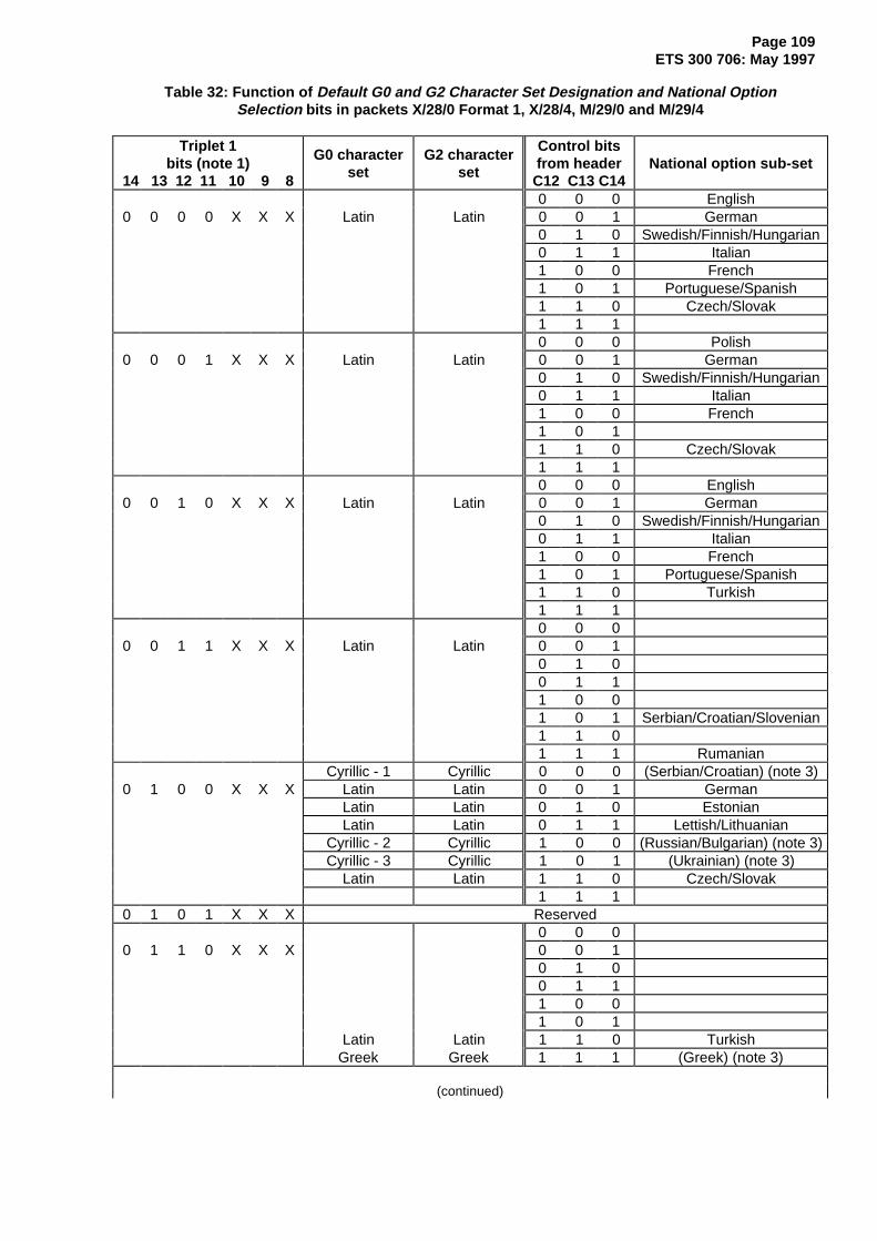
Page 109ETS 300 706: May 1997
Table 32: Function of Default G0 and G2 Character Set Designation and National OptionSelection bits in packets X/28/0 Format 1, X/28/4, M/29/0 and M/29/4
Triplet 1bits (note 1)
14 13 12 11 10 9 8
G0 characterset
G2 characterset
Control bitsfrom headerC12 C13 C14
National option sub-set
0 0 0 English0 0 0 0 X X X Latin Latin 0 0 1 German
0 1 0 Swedish/Finnish/Hungarian0 1 1 Italian1 0 0 French1 0 1 Portuguese/Spanish1 1 0 Czech/Slovak1 1 10 0 0 Polish
0 0 0 1 X X X Latin Latin 0 0 1 German0 1 0 Swedish/Finnish/Hungarian0 1 1 Italian1 0 0 French1 0 11 1 0 Czech/Slovak1 1 10 0 0 English
0 0 1 0 X X X Latin Latin 0 0 1 German0 1 0 Swedish/Finnish/Hungarian0 1 1 Italian1 0 0 French1 0 1 Portuguese/Spanish1 1 0 Turkish1 1 10 0 0
0 0 1 1 X X X Latin Latin 0 0 10 1 00 1 11 0 01 0 1 Serbian/Croatian/Slovenian1 1 01 1 1 Rumanian
Cyrillic - 1 Cyrillic 0 0 0 (Serbian/Croatian) (note 3)0 1 0 0 X X X Latin Latin 0 0 1 German
Latin Latin 0 1 0 EstonianLatin Latin 0 1 1 Lettish/Lithuanian
Cyrillic - 2 Cyrillic 1 0 0 (Russian/Bulgarian) (note 3)Cyrillic - 3 Cyrillic 1 0 1 (Ukrainian) (note 3)
Latin Latin 1 1 0 Czech/Slovak1 1 1
0 1 0 1 X X X Reserved0 0 0
0 1 1 0 X X X 0 0 10 1 00 1 11 0 01 0 1
Latin Latin 1 1 0 TurkishGreek Greek 1 1 1 (Greek) (note 3)
(continued)

Page 110ETS 300 706: May 1997
Table 32 (concluded): Function of Default G0 and G2 Character Set Designation and NationalOption Selection bits in packets X/28/0 Format 1, X/28/4, M/29/0 and M/29/4
Triplet 1bits (note 1)
14 13 12 11 10 9 8
G0 characterset
G2 characterset
Control bitsfrom headerC12 C13 C14
National option sub-set
0 1 1 1 X X X ReservedLatin Arabic 0 0 0 English
1 0 0 0 X X X 0 0 10 1 00 1 1
Latin Arabic 1 0 0 French1 0 11 1 0
Arabic Arabic 1 1 1 (Arabic) (note 3)1 0 0 1 X X X Reserved
0 0 01 0 1 0 X X X 0 0 1
0 1 00 1 11 0 0
Hebrew Arabic 1 0 1 (Hebrew) (note 3)1 1 0
Arabic Arabic 1 1 1 (Arabic) (note 3)Other values Reserved
NOTE 1: For packets X/28/0 format 1 and X/28/4, bits 8, 9 and 10 are set to the same values as thecontrol bits in the page header packet, i.e. bit 10 = C12, bit 9 = C13 and bit 8 = C14.For packets M/29/0 and M/29/4 these bits should be set to the most common value of C12, C13and C14 used in that magazine, see annex E.9.
NOTE 2: Entries in the table with no character set or national option sub-set specified are reserved.NOTE 3: No separate sub-sets exist for the national options shown in brackets. The characters are
contained within the appropriate G0 set.
15.3 Second G0 Set Designation and National Option Set Selection
The Second G0 Set Designation and Nation Option Selection value (Triplet 1, bits 15 to 18 andTriplet 2, bits 1 to 3) in the relevant packets 28 and 29 defines the second G0 set. Typically the second G0set will contain a different alphabet compared to the default G0 set, allowing words written in differentalphabets to be mixed on the same page. This is accessed by a Level 1 decoder through the charactercodes on the Level 1 page following the first ESC character within a display row. Subsequent ESCcharacters cause the decoder to alternate between the G0 set defined by the Default G0 and G2Character Set Designation and National Option Selection value and this second G0 set. A further functionof this value is to define the national option character sub-set to appear in the national option positions ofthis second G0 set. The national option sub-set selected by the C12, C13 and C14 bits is not relevant tothe secondary set. Where a transmission does not use two G0 sets, this second value is set to 1111111.A decoder may interpret this value to mean that the ESC function should be disabled for this page(packets X/28/0 Format 1 or X/28/4) or magazine (packets M/29/0 or M/29/4). The coding is shown intable 33.
This information is unlikely to be interpreted by Level 1 or 1.5 decoders but it is required by Level 2.5 and3.5 decoders to ensure they function correctly when receiving Level 1.5 transmissions. This value doesnot specify any parameter of a Level 2.5 or 3.5 transmission. Also, a G2 set is not designated by thisvalue. The G2 set designated by the Default G0 and G2 Character Set Designation and National OptionSelection value remains selected throughout and is independent of the ESC function.

Page 111ETS 300 706: May 1997
Table 33: Function of Second Language Designation and National Option Selection bits in packetsX/28/0 Format 1, X/28/4, M/29/0 and M/29/4
Triplet 2 Triplet 1bits bits
3 2 1 18 17 16 15
G0 characterset National option sub-set
0 0 0 0 0 0 0 English0 0 0 0 0 0 1 Latin German0 0 0 0 0 1 0 Swedish/Finnish/Hungarian0 0 0 0 0 1 1 Italian0 0 0 0 1 0 0 French0 0 0 0 1 0 1 Portuguese/Spanish0 0 0 0 1 1 0 Czech/Slovak0 0 0 0 1 1 10 0 0 1 0 0 0 Polish0 0 0 1 0 0 1 Latin German0 0 0 1 0 1 0 Swedish/Finnish/Hungarian0 0 0 1 0 1 1 Italian0 0 0 1 1 0 0 French0 0 0 1 1 0 10 0 0 1 1 1 0 Czech/Slovak0 0 0 1 1 1 10 0 1 0 0 0 0 English0 0 1 0 0 0 1 Latin German0 0 1 0 0 1 0 Swedish/Finnish/Hungarian0 0 1 0 0 1 1 Italian0 0 1 0 1 0 0 French0 0 1 0 1 0 1 Portuguese/Spanish0 0 1 0 1 1 0 Turkish0 0 1 0 1 1 10 0 1 1 0 0 00 0 1 1 0 0 1 Latin0 0 1 1 0 1 00 0 1 1 0 1 10 0 1 1 1 0 00 0 1 1 1 0 1 Serbian/Croatian/Slovenian0 0 1 1 1 1 00 0 1 1 1 1 1 Rumanian0 1 0 0 0 0 0 Cyrillic - 1 (Serbian/Croatian) (note 2)0 1 0 0 0 0 1 Latin German0 1 0 0 0 1 0 Latin Estonian0 1 0 0 0 1 1 Latin Lettish/Lithuanian0 1 0 0 1 0 0 Cyrillic - 2 (Russian/Bulgarian) (note 2)0 1 0 0 1 0 1 Cyrillic - 3 (Ukrainian) (note 2)0 1 0 0 1 1 0 Latin Czech/Slovak (Latin)0 1 0 0 1 1 10 1 0 1 X X X Reserved0 1 1 0 0 0 00 1 1 0 0 0 10 1 1 0 0 1 00 1 1 0 0 1 10 1 1 0 1 0 00 1 1 0 1 0 1
(continued)

Page 112ETS 300 706: May 1997
Table 33 (concluded): Function of Second Language Designation and National OptionSelection bits in packets X/28/0 Format 1, X/28/4, M/29/0 and M/29/4
Triplet 2 Triplet 1bits bits
3 2 1 18 17 16 15
G0 characterset National option sub-set
0 1 1 0 1 1 0 Latin Turkish0 1 1 0 1 1 1 Greek (Greek) (note 2)0 1 1 1 X X X Reserved1 0 0 0 0 0 0 Latin English1 0 0 0 0 0 11 0 0 0 0 1 01 0 0 0 0 1 11 0 0 0 1 0 0 Latin French1 0 0 0 1 0 11 0 0 0 1 1 01 0 0 0 1 1 1 Arabic (Arabic) (note 2)1 0 0 1 X X X Reserved1 0 1 0 0 0 01 0 1 0 0 0 11 0 1 0 0 1 01 0 1 0 0 1 11 0 1 0 1 0 01 0 1 0 1 0 1 Hebrew (Hebrew) (note 2)1 0 1 0 1 1 01 0 1 0 1 1 1 Arabic (Arabic) (note 2)
Other values Reserved1 1 1 1 1 1 1 No second G0 set required
NOTE 1: Entries in the table with no character set or national optionsub-set specified are reserved.
NOTE 2: No separate sub-sets exist for the national options shown inbrackets. The characters are contained within the appropriateG0 set.
15.4 Modified G0 and G2 Character Set Designation
At Levels 2.5 and 3.5, the Modified G0 and G2 Character Set Designation triplet allows alternative G0 andG2 character sets to be selected. These are only accessible by Level 2.5 and 3.5 triplets. The coding,shown in table 34, is similar to that used in tables 32 and 33.
NOTE: When the G0 set is referenced by a triplet, characters with addresses 2/0 to 7/F areselectable and the set of characters is not modified by any national option sub-set selection.

Page 113ETS 300 706: May 1997
Table 34: Function of the Modified G0 and G2 Character Set Designation triplet
Data Field Bits 18 17 16 15 14 13 12
G0 characterset
G2 characterset
0 0 0 0 X X X Latin Latin0 0 0 1 X X X Latin Latin0 0 1 0 X X X Latin Latin0 0 1 1 X X X Latin Latin0 1 0 0 0 0 0 Cyrillic - 1 Cyrillic0 1 0 0 0 0 1 Latin Latin0 1 0 0 0 1 0 Latin Latin0 1 0 0 0 1 1 Latin Latin0 1 0 0 1 0 0 Cyrillic - 2 Cyrillic0 1 0 0 1 0 1 Cyrillic - 3 Cyrillic0 1 0 0 1 1 0 Latin Latin0 1 0 0 1 1 10 1 0 1 X X X Reserved0 1 1 0 0 0 00 1 1 0 0 0 10 1 1 0 0 1 00 1 1 0 0 1 10 1 1 0 1 0 00 1 1 0 1 0 10 1 1 0 1 1 0 Latin Latin0 1 1 0 1 1 1 Greek Greek0 1 1 1 X X X Reserved1 0 0 0 0 0 0 Latin Arabic1 0 0 0 0 0 11 0 0 0 0 1 01 0 0 0 0 1 11 0 0 0 1 0 0 Latin Arabic1 0 0 0 1 0 11 0 0 0 1 1 01 0 0 0 1 1 1 Arabic Arabic1 0 0 1 X X X Reserved1 0 1 0 0 0 01 0 1 0 0 0 11 0 1 0 0 1 01 0 1 0 0 1 11 0 1 0 1 0 01 0 1 0 1 0 1 Hebrew Arabic1 0 1 0 1 1 01 0 1 0 1 1 1 Arabic Arabic
Other values ReservedNOTE 1: Entries in the table with no character sets
specified are reserved.
15.5 Spacing attributes
Codes 0/0 to 1/F within packets X/0 to X/24 of a Level 1 page select the spacing attributes defined insubclause 12.2.
15.6 Alphanumeric Character Sets
It should be noted that the precise appearance of the characters defined here is a decoder option. Thecharacters shown are based on a matrix of 12 pixels horizontally and 10 pixels vertically.

Page 114ETS 300 706: May 1997
15.6.1 Latin G0 Set
Table 35: Latin G0 Primary Set
B7 B6 B5010 011 100 101 110 111
B4 B3 B2 B1 Col 2 3 4 5 6 7
0
0
0
0
0
0
0
0
1
1
1
1
1
1
1
1
0
0
0
0
1
1
1
1
0
0
0
0
1
1
1
1
0
0
1
1
0
0
1
1
0
0
1
1
0
0
1
1
0
1
0
1
0
1
0
1
0
1
0
1
0
1
0
1
Row
0
1
2
3
4
5
6
7
8
9
A
B
C
D
E
F
NOTE 1: The character in position 2/0is to be interpreted asSPACE.
NOTE 2: The characters at theshaded positions apply whenthe set is accessed viapackets X/26. Charactersfrom a national option sub-set from table 36 occupythese positions when the setis addressed directly from aLevel 1 page.
NOTE 3: The character in position 7/Foccupies an area equivalentto that of any characterwhich does not include adescender. It is thus arectangle surrounded by thebackground colour.
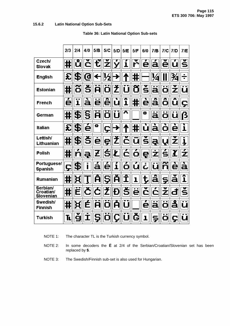
Page 115ETS 300 706: May 1997
15.6.2 Latin National Option Sub-Sets
Table 36: Latin National Option Sub-sets
NOTE 1: The character TL is the Turkish currency symbol.
NOTE 2: In some decoders the Ë at 2/4 of the Serbian/Croatian/Slovenian set has beenreplaced by $.
NOTE 3: The Swedish/Finnish sub-set is also used for Hungarian.

Page 116ETS 300 706: May 1997
15.6.3 Latin G2 Set
Table 37: Latin G2 Supplementary Set
2 3 4 5 6 7
0
1
2
3
4
5
6
7
8
9
A
B
C
D
E
F
NOTE 1: The character in position 2/0 is to beinterpreted as SPACE.
NOTE 2: Column 4 contains diacritical marks forassociation with G0 set characters.
NOTE 3: The characters in positions 5/6, 5/7 and5/8 are in addition to those specified inISO 6937/2 [4].
NOTE 4: The character in position 5/6 representsthe European currency symbol.
NOTE 5: The characters codes 5/9, 5/A, 5/B and6/5 should not be transmitted.
NOTE 6: The character in position 7/F occupies anarea equivalent to that of any characterwhich does not include a descender. It isthus a rectangle surrounded by thebackground colour.
NOTE 7: Bit allocations are as for table 35.
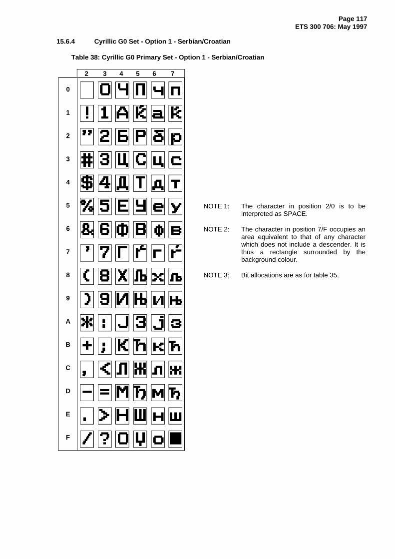
Page 117ETS 300 706: May 1997
15.6.4 Cyrillic G0 Set - Option 1 - Serbian/Croatian
Table 38: Cyrillic G0 Primary Set - Option 1 - Serbian/Croatian
2 3 4 5 6 7
0
1
2
3
4
5
6
7
8
9
A
B
C
D
E
F
NOTE 1: The character in position 2/0 is to beinterpreted as SPACE.
NOTE 2: The character in position 7/F occupies anarea equivalent to that of any characterwhich does not include a descender. It isthus a rectangle surrounded by thebackground colour.
NOTE 3: Bit allocations are as for table 35.

Page 118ETS 300 706: May 1997
15.6.5 Cyrillic G0 Set - Option 2 - Russian/Bulgarian
Table 39: Cyrillic G0 Primary Set - Option 2 - Russian/Bulgarian
2 3 4 5 6 7
0
1
2
3
4
5
6
7
8
9
A
B
C
D
E
F
NOTE 1: The character in position 2/0 is to beinterpreted as SPACE.
NOTE 2: The character in position 7/F occupies anarea equivalent to that of any characterwhich does not include a descender. It isthus a rectangle surrounded by thebackground colour.
NOTE 3: Bit allocations are as for table 35.

Page 119ETS 300 706: May 1997
15.6.6 Cyrillic G0 Set - Option 3 - Ukrainian
Table 40: Cyrillic G0 Primary Set - Option 3 - Ukrainian
2 3 4 5 6 7
0
1
2
3
4
5
6
7
8
9
A
B
C
D
E
F
NOTE 1: The character in position 2/0 is to beinterpreted as SPACE.
NOTE 2: The character in position 7/F occupies anarea equivalent to that of any characterwhich does not include a descender. It isthus a rectangle surrounded by thebackground colour.
NOTE 3: Bit allocations are as for table 35.

Page 120ETS 300 706: May 1997
15.6.7 Cyrillic G2 Set
Table 41: Cyrillic G2 Supplementary Set
2 3 4 5 6 7
0
1
2
3
4
5
6
7
8
9
A
B
C
D
E
F
NOTE 1: The character in position 2/0 is to beinterpreted as SPACE.
NOTE 2: The characters codes 2/6 and 2/8 shouldnot be transmitted.
NOTE 3: Column 4 contains diacritical marks forassociation with G0 set characters.
NOTE 4: The characters in positions 5/6, 5/7 and5/8 are in addition to those specified inISO 6937/2 [4].
NOTE 5: The character in position 5/6 representsthe European currency symbol.
NOTE 6: Bit allocations are as for table 35.

Page 121ETS 300 706: May 1997
15.6.8 Greek G0 Set
Table 42: Greek G0 Primary Set
2 3 4 5 6 7
0
1
2
3
4
5
6
7
8
9
A
B
C
D
E
F
NOTE 1: The character in position 2/0 is to beinterpreted as SPACE.
NOTE 2: The character in position 7/F occupies anarea equivalent to that of any characterwhich does not include a descender. It isthus a rectangle surrounded by thebackground colour.
NOTE 3: Bit allocations are as for table 35.

Page 122ETS 300 706: May 1997
15.6.9 Greek G2 Set
Table 43: Greek G2 Supplementary Set
2 3 4 5 6 7
0
1
2
3
4
5
6
7
8
9
A
B
C
D
E
F
NOTE 1: The character in position 2/0 is to beinterpreted as SPACE.
NOTE 2: Column 4 contains diacritical marks forassociation with G0 set characters.
NOTE 3: The characters in positions 5/6, 5/7 and5/8 are in addition to those specified inISO 6937/2 [4].
NOTE 4: The character in position 5/6 representsthe European currency symbol.
NOTE 5: The character in position 7/F occupies anarea equivalent to that of any characterwhich does not include a descender. It isthus a rectangle surrounded by thebackground colour.
NOTE 6: Bit allocations are as for table 35.
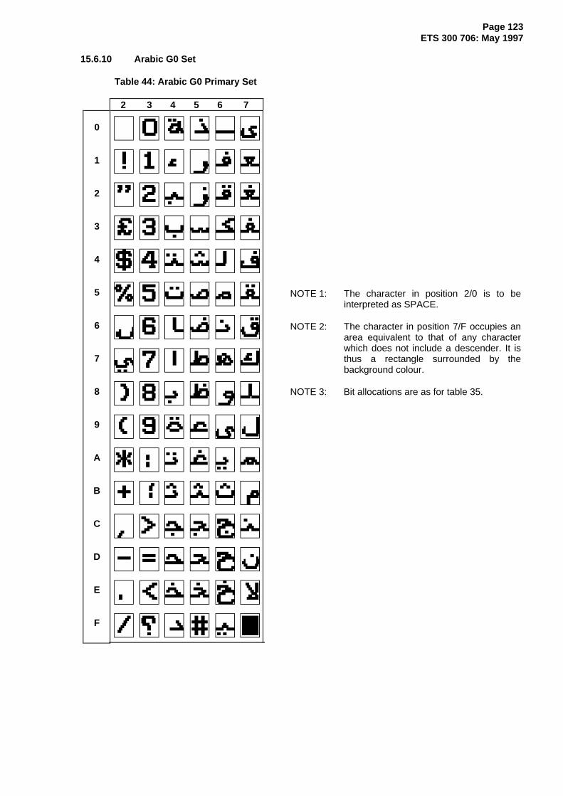
Page 123ETS 300 706: May 1997
15.6.10 Arabic G0 Set
Table 44: Arabic G0 Primary Set
2 3 4 5 6 7
0
1
2
3
4
5
6
7
8
9
A
B
C
D
E
F
NOTE 1: The character in position 2/0 is to beinterpreted as SPACE.
NOTE 2: The character in position 7/F occupies anarea equivalent to that of any characterwhich does not include a descender. It isthus a rectangle surrounded by thebackground colour.
NOTE 3: Bit allocations are as for table 35.

Page 124ETS 300 706: May 1997
15.6.11 Arabic G2 Set
Table 45: Arabic G2 Supplementary Set
2 3 4 5 6 7
0
1
2
3
4
5
6
7
8
9
A
B
C
D
E
F
NOTE 1: The character in position 2/0 is to beinterpreted as SPACE.
NOTE 2: Column 4 contains diacritical marks forassociation with G0 set characters.
NOTE 3: The characters in positions 5/6, 5/7 and5/8 are in addition to those specified inISO 6937/2 [4].
NOTE 4: The character in position 5/6 representsthe European currency symbol.
NOTE 5: The character in position 7/F occupies anarea equivalent to that of any characterwhich does not include a descender. It isthus a rectangle surrounded by thebackground colour.
NOTE 6: Bit allocations are as for table 35.

Page 125ETS 300 706: May 1997
15.6.12 Hebrew G0 Set
Table 46: Hebrew G0 Primary Set
2 3 4 5 6 7
0
1
2
3
4
5
6
7
8
9
A
B
C
D
E
F
NOTE 1: The character in position 2/0 is to beinterpreted as SPACE.
NOTE 2: The character in position 7/F occupies anarea equivalent to that of any characterwhich does not include a descender. It isthus a rectangle surrounded by thebackground colour.
NOTE 3: The character at 7/B is the Shekelcurrency sign.
NOTE 4: Bit allocations are as for table 35.

Page 126ETS 300 706: May 1997
15.7 Graphics Character Sets
15.7.1 G1 Block Mosaics Set
Table 47: G1 Block Mosaics Set
2 3 4 5 6 7
0
1
2
3
4
5
6
7
8
9
A
B
C
D
E
F
NOTE 1: The locations in columns 4 and 5indicated by (1) contain the correspondingcharacters from the G0 set currentlyselected.
NOTE 2: When addressed from the Level 1 page,the characters at the shaded positions incolumns 4 and 5 are taken from thenational option sub-set currently selectedvia the C12, C13 and C14 control bits andany "ESC" commands in force at thattime.
NOTE 3: When selected by a packet X/26command, the characters at the shadedpositions in columns 4 and 5 are thecorresponding characters in the G0 setcurrently selected.
NOTE 4: The character in position 2/0 is to beinterpreted as a mosaics SPACE.
NOTE 5: The dark areas of the characters incolumns 2, 3, 6 and 7 are displayed in theforeground colour.
NOTE 6: The characters are shown in theircontiguous form in the table. An exampleof the separated form is shown below.
Contiguous form
Separated form
NOTE 7: Bit allocations are as for table 35.

Page 127ETS 300 706: May 1997
15.7.2 G3 Smooth Mosaics and Line Drawing Set
Table 48: G3 Smooth Mosaics and Line Drawing Set
2 3 4 5 6 7
0
1
2
3
4
5
6
7
8
9
A
B
C
D
E
F
NOTE 1: The character at 5/F permits the display ofbackground colour.
NOTE 2: No character is assigned to the positionsmarked (2) and the corresponding codesshould not be transmitted.
NOTE 3: The dark areas of the characters aredisplayed in the foreground colour.
NOTE 4: The character at position 2/F representsthe activation of alternate dots of thematrix.
NOTE 5: Bit allocations are as for table 35.

Page 128ETS 300 706: May 1997
Annex A (normative): Encoding Rules
A.1 Page numbering
There is a need for page headers to be available without any following data for time filling and pageterminating applications. There is also a need for a page address to be available for internal use indecoders that will not occur in transmission. The following rules apply:
1) Any page address up to and including hexadecimal FE with a sub-code up to and including 3F7E,can be used for a page carrying data and can be specified as a linked page.
2) Pages address number FF in any magazine, with any sub-code in the range 0000 to 3F7E may beused for time filling and as a terminator. Pages with these addresses will not carry data foracquisition by a decoder.
3) Page header packets with the page address FF, sub-code 3F7F, will not be transmitted. Thisaddress will occur as a null link in packets with Y = 27 and 8/30.
To provide efficient handling of pages with sub-pages the following rules apply:
1) Pages with no sub-pages associated should be coded Mxx-0000.
2) Pages intended for display with sub-pages should have sub-pages coded sequentially from Mxx-0001 to Mxx-0009 and then Mxx-0010 to Mxx-0019 and similarly using the decimal values of sub-code nibbles S2 and S1 to Mxx-0079.
3) The sub-code of each sub-page of a data page (e.g. MOT, POP, GPOP, DRCS, GDRCS, MIP)should be coded sequentially nnXs , where:
nn comprises S4 and S3 elements and indicates the last packet that would be transmitted according toannex B.2 if the sub-page was to be broadcast without interruption. S3 and S4 provide a 6-bit value, withS4 as the 2 MSBs and S3 as the 4 LSBs. The valid range is 1 to 41 (decimal), with values 1 to25 representing packets X/1 to X/25, and values 26 to 41 representing packets X/26/0 to X/26/15.
NOTE 1: When a partial page is being broadcast, this value represents the last packet thedecoder will receive during this transmission of the page. It is not modified if the pageis transmitted in fragments.
X comprises the S2 element and is an update indicator which is incremented (modulo 8) each time achange is made to this sub-page.
NOTE 2: This indicator may still be incremented even when changes have not been madebetween the last partial update and a full transmission if there has been a multiple of 8changes made since the last full transmission.
s comprises the S1 element and uniquely identifies the sub-page. The first sub-page has S1 set to 0 andthe value is incremented for each successive sub-page used.
4) If a sub page editorial content is not different from the preceding sub-page the current sub-pagemay be transmitted with the same sub-code as the preceding sub-page.
NOTE 3: Some existing decoders may require a non-zero sub-code to ensure that each versionof the rotating page is displayed and/or collected. A sub-code outside the range 1 to 79(S2, S1) should be used in order to prevent sub-page collecting decoders indicatingthat a page is a rotating page when it only has one sub-page ( i.e. a rotating advert ).

Page 129ETS 300 706: May 1997
A.2 Use of control bits C4 (Erase Page) and C8 (Update Indicator)
These rules only apply to pages intended for display:
1) The Update Indicator bit (C8) is used by the editor specifically to indicate that an update hasoccurred. The expected effect in the decoder is that, where a page display has been cancelled byan appropriate user key, ("cancel page", "picture" etc.), the setting of the Update Indicator bit willcause a prompt, which may involve automatic redisplay of the page. An application where this isstandard practice is "Newsflash" pages. The unnecessary or inappropriate setting of the UpdateIndicator bit can cause annoying redisplay of a page or Newsflash that a user wishes to cancel. Thesetting of the Update Indicator bit is thus an editorial decision.
2) When the Erase bit C4 is set, that page is expected to be erased completely and a new pagewritten into memory.
3) The effect of both of these bits applies to packets 1 to 28 inclusively and for any data written by adefault object.
A.3 Backwards compatibility in X/26 addressing
The designation code of the first transmitted packet 26 of a page of any type should be '0'. Followingpackets 26 should use ascending, contiguous designation code values.
NOTE: Some existing Level 1.5 and PDC decoders may not respond to packet X/26/15.
The most recent value of the address bits in the range 40 to 63 will be treated by existing Level 1.5decoders as setting the row co-ordinate of the Active Position, regardless of the mode value of the triplet.
For any display position there should be only one column address group selecting a character which couldbe interpreted by a Level 1.5 decoder.
To ensure compatibility with Level 1.5 decoders, a Termination Marker triplet should be transmitted afterthe local enhancement data, prior to any Object Definition triplets. For the benefit of Level 2.5 and 3.5decoders, the data field of this Termination Marker should be set to identify the type and position of thedata being terminated according to subclause 12.3.3, mode 11111.
A.4 Addressing order for enhancement triplets
In order to simplify decoding software and avoid excessive re-writing of screen data, local enhancementdata triplets and the elements of objects shall be encoded in order of the screen address, left to right andtop to bottom of the screen. (Screen address is determined by the encoded row and column addresses,i.e. data for columns 0 to 39 of the row comes before data for the right side-panel in columns 40 to 55which in turn comes before data for the left side-panel in columns 56 to 71).
A decoder may ignore any triplet from the local enhancement data or from any object which addresses ascreen location earlier than that addressed by the previous triplet from the same source.
The following row address group triplets and all column address triplets cause the Active Position to bemodified and shall be encoded in screen address order:
Mode 00001 Full Row ColourMode 00100 Set Active PositionMode 00111 Address Display Row 0
Any one object may not address more than one display area. For example, if an object addresses thenormal page, it shall not itself contain data for a side panel but can call another object for the side-panel.

Page 130ETS 300 706: May 1997
The transmission order for row address group triplets which set screen or row colour is:
Mode 00000 Full Screen ColourMode 00111 Address Display Row 0Mode 00001 Full Row Colour
A.5 Rules for row and screen colours
Screen colour is determined by (in order of precedence):
1) A Full Screen Colour triplet explicitly invoked;2) The default screen colour invoked by a packet 28 for the page;3) The default screen colour invoked by a packet 29 for the magazine;4) Default to Black.
NOTE 1: There should be only one full screen colour definition per page and it should be thefirst triplet encountered that defines any attribute or character for the page. Forcompatibility with Level 1.5 decoders, an address field value of 41 (decimal) isrecommended.
Row colour is determined by (in order of precedence):
1) A Full Row Colour triplet explicitly invoked (latest takes precedence);2) The screen colour already invoked;3) The default row colour invoked by packet 28 for the page;4) The default row colour invoked by packet 29 for the magazine;5) Default to Black.
NOTE 2: There should be only one full row colour definition per row and it should be the firsttriplet encountered that defines any attribute or character for that row.
A.6 Object definition pages
If an object definition page uses packets X/1 to X/25 then a packet X/28/0 Format 1 shall be transmitted toindicate the format of the packets.
A.7 Rules for the overlapping and interleaving of objects
A.7.1 Overlapping rules
Two more objects are said to "overlap" if they each address the same character cell on a row.
Objects of different types (Active, Adaptive, Passive) may overlap. The priority order for display is:
Highest PassiveAdaptive
Lowest Active
Two or more Active Objects may overlap provided that they do not re-define attributes of the sameattribute type.
Adaptive Objects shall not overlap one another.
Two or more Passive Objects may overlap one another.
Where objects of the same type are allowed to overlap, the priority order for display is the order of theirinvocation, with the latest invoked object taking precedence.

Page 131ETS 300 706: May 1997
The four "attribute types" are defined as:
Foreground ColourBackground ColourFlashingDisplay Attributes - Double Height
Double WidthBoxing/WindowConcealInvertSeparated Mosaic Graphics / Underline
A.7.2 Interleaving rules
Two or more objects are said to be "interleaved" if one or more of them addresses character cellsbetween cells addressed by another on the same row.
Example: Column 23 24 25 26 27Object A Object A Object B Object A Object B
Objects of different types (Active, Passive, Adaptive) may be freely interleaved.
Two or more Active Objects may be freely interleaved.
Two or more Adaptive Objects may only be interleaved if they do not re-define any attribute.
Two or more Passive Objects may be freely interleaved.
A.8 Number of objects per page
1) The total number of objects of any one type invoked in one display page shall be limited to 127.
2) The maximum number of objects of all types can be "open" at any one time, regardless of whetherthey affect a screen location or not, is 15. An object is "open" from the Active Position at invocationup to and including the last position explicitly addressed by the object. The "open" area includes theside-panel locations. Examples of the "open" area are shown in figure A.1.
56 -71 Columns 0 -39 40-55 56 -71 Columns 0 -39 40 -55
I O,I
Open Area Object Open Area
(note) T
Object
T
I = Object Invocation, T = End of object O,I = Object Invocation preceded by OriginModifier, T = End of object
NOTE: The "open" area does not extend into the left-hand side-panel on this row as the columnaddresses are beyond the last cell addressed by the object.
Figure A.1: Definition of the "Open Area" for Objects

Page 132ETS 300 706: May 1997
3) The maximum number of objects that may be opened successively by the local enhancement data,or by any other object, without any intervening displayable character or attribute being written is 15.
A.9 Coding of packets 8/30, Formats 1 and 2
1) When packets 8/30 Format 1 and 8/30 Format 2 are both present in a given transmission, the datain bytes 7 to 12 and 26 to 45 of each packet shall be identical.
2) Where a broadcaster has not been allocated an official NI value, bytes 13 and 14 of packet 8/30format 1 should be coded with all bits set to 0.

Page 133ETS 300 706: May 1997
Annex B (normative): Transmission Rules
B.1 Transmission of basic Teletext pages with a page erasure interval
For compatibility with earlier decoders in the field, a page clearing interval of 20 ms should be maintainedin the transmission between the header and any packets of a page that is intended to be interpreted by aLevel 1 or 1.5 decoder. This time interval is required by many decoders for erasing the previous page frommemory.
B.2 Transmission order of packets with Y = 26, 27 and 28
1) To permit the most efficient operation of a decoder the transmission of a page header packet(Y = 0) shall be followed by the transmission of any packets with Y = 27 (containing links to otherpages) and Y = 28 (containing formatting information to assist interpretation of the rest of the page),in that order.
2) In the case of pages intended for direct display, packets with Y = 26 shall be transmitted before anypackets with Y = 1 to Y = 25. Packets with Y = 26 shall be transmitted in ascending order ofdesignation code.
If the transmission of the page is interrupted and then restarted, any packets with Y = 27, Y = 28and Y = 26 shall be re-transmitted following the page header, regardless of the state of the C4 bitfor that page.
3) In the case of pages intended for further processing, e.g. presentation enhancement data pages,packets with Y = 1 to Y = 26 shall be transmitted in ascending order of packet address, and inascending order of designation code for packets with Y = 26.
If the transmission of the page is interrupted and then restarted, any packets with Y = 27 and Y = 28shall be re-transmitted following the page header.
B.3 Serial mode transmission
A serial mode transmission is defined by control bit C11 in packet X/0 being set to 1.
1) Any packets in the range X/1 to X/28 transmitted between two successive page headers are part ofthe page defined by the first page header.
2) They shall carry the same magazine address as that page header.
3) The transmission between these two page headers of packets in the range X/1 to X/28 from othermagazines is not permitted.
4) The second page header may be from any magazine.
5) Packets M/29 from any magazine and independent packets with addresses 30 and 31 may beinserted at any point in the transmission sequence.
In practical terms, the following statements may be made:
a) In a transmission multiplexed with a video signal, it is likely that each page will be transmittedon the maximum number of VBI lines available, and all pages from all magazines will betransmitted one after the other, although not necessarily in numerical sequence.
b) It is preferable for a decoder to use all page headers (providing control bit C9 is set to 0) fromall magazines when displaying rolling headers.

Page 134ETS 300 706: May 1997
B.4 Parallel mode transmission
A parallel mode transmission is defined by control bit C11 in packet X/0 being set to 0.
1) Packets in the range X/0 to X/28 from any magazine may be transmitted in any sequence, providingthe packets of an individual page are transmitted according to annex B.2.
2) Following a page header with a certain magazine address, only those packets in the range X/1 toX/28 with the same magazine address belong to the page defined by the page header.
3) Packets M/29 from any magazine, packets 30 and 31 may be inserted at any point in thetransmission sequence.
In practical terms, the following statements may be made:
a) In a transmission multiplexed with a video signal, it is likely that pages from one or moremagazines will be allocated to groups of VBI lines for transmission.
Thus a single VBI period can consist of packets from a number of different magazines.
Pages within each magazine need not to be transmitted in numerical sequence.
b) It is preferable for a decoder to use page headers (providing control bit C9 set to 0) from onlyone magazine when displaying rolling headers.
B.5 Transmission of packets 8/30
1) Packets 8/30 Format 1 shall be transmitted within the VBI immediately following the boundarybetween clock-seconds.
2) Up to four Format 2 packets 8/30 may be transmitted within a one second interval interleaved witha Format 1 packet 8/30 (if any).
3) The transmission of any packet 8/30 should be separated by at least 200 ms from any followingpacket 8/30.
B.6 Rules for the transmission of presentation enhancement data
1) Each presentation enhancement page, e.g. MOT, POP, GPOP, DRCS, GDRCS, and all non-pagerelated presentation enhancement packets, e.g. M/29, shall be transmitted in full every 20 smaximum.
2) Presentation enhancement pages may be transmitted without a 20 ms interval between the pageheader and the remaining packets of the page.
3) These pages may be transmitted as continuous burst where one page is followed immediately bythe next.
4) The format for the sub-code is defined in annex A, clause A.1.
5) When the Erase bit, C4, is set, a decoder should erase all the packets belonging to the previousversion of the page.
6) Partial updates, comprising the page header and the changed packet(s), can be sent between eachfull transmission. The C13 bit is set to 1 to indicate a partial page.
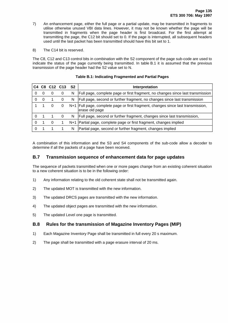
Page 135ETS 300 706: May 1997
7) An enhancement page, either the full page or a partial update, may be transmitted in fragments toutilise otherwise unused VBI data lines. However, it may not be known whether the page will betransmitted in fragments when the page header is first broadcast. For the first attempt attransmitting the page, the C12 bit should set to 0. If the page is interrupted, all subsequent headersused until the last packet has been transmitted should have this bit set to 1.
8) The C14 bit is reserved.
The C8, C12 and C13 control bits in combination with the S2 component of the page sub-code are used toindicate the status of the page currently being transmitted. In table B.1 it is assumed that the previoustransmission of the page header had the S2 value set to N.
Table B.1: Indicating Fragmented and Partial Pages
C4 C8 C12 C13 S2 Interpretation
0 0 0 0 N Full page, complete page or first fragment, no changes since last transmission
0 0 1 0 N Full page, second or further fragment, no changes since last transmission
1 1 0 0 N+1 Full page, complete page or first fragment, changes since last transmission,erase old page
0 1 1 0 N Full page, second or further fragment, changes since last transmission,
0 1 0 1 N+1 Partial page, complete page or first fragment, changes implied
0 1 1 1 N Partial page, second or further fragment, changes implied
A combination of this information and the S3 and S4 components of the sub-code allow a decoder todetermine if all the packets of a page have been received.
B.7 Transmission sequence of enhancement data for page updates
The sequence of packets transmitted when one or more pages change from an existing coherent situationto a new coherent situation is to be in the following order:
1) Any information relating to the old coherent state shall not be transmitted again.
2) The updated MOT is transmitted with the new information.
3) The updated DRCS pages are transmitted with the new information.
4) The updated object pages are transmitted with the new information.
5) The updated Level one page is transmitted.
B.8 Rules for the transmission of Magazine Inventory Pages (MIP)
1) Each Magazine Inventory Page shall be transmitted in full every 20 s maximum.
2) The page shall be transmitted with a page erasure interval of 20 ms.

Page 136ETS 300 706: May 1997
Annex C (normative): Decoding Rules
C.1 Relationship between the display planes
Transparency (entry 0 in CLUT 1) in a higher plane makes the plane below visible. There are three displayplanes with a defined priority order:
1) Foreground / Background;2) Full Screen / Full Row Colour;3) Video.
The action of the Boxing / Window attribute in the conjunction with the Newsflash and Subtitle control bitsis summarized in table C.1.
Table C.1: Display Priorities
Foreground/
Background
Colour
Full RowColour
Boxed orWindowed
Area
Newsflash orSubtitle Page
Control BitResult
� � 0 0 F/ B Colour
� � 0 1 Video
� � 1 0 F/ B Colour
� � 1 1 F/ B Colour
� � 0 0 F/ B Colour
� � 0 1 Video
� � 1 0 F/ B Colour
� � 1 1 F/ B Colour� � 0 0 Row Colour� � 0 1 Video� � 1 0 Video� � 1 1 Row Colour� � 0 0 Video� � 0 1 Video� � 1 0 Video� � 1 1 Video
� = CLUT1, entry 0 (Transparent), � = any other colour (not transparent)
C.2 Rules for determining priorities of spacing and non-spacing attributes
Where two or more attributes of the same type are in contention at the same character location it isnecessary to have rules to establish which will take effect. The basic rule is that the latest one takesprecedence where consideration is given to the following, in the order below:
1) The locations at which the contending attributes first take effect;
2) The locations at which the contending attributes are placed (but only if the priority cannot beresolved by rule 1);
3) The relative positions in the transmission of the contending attributes (but only if the priority cannotbe resolved by rules 1 or 2).

Page 137ETS 300 706: May 1997
Examples:
n -1 n
leve l 1 row
X /26
a-red A
fgndblue
Foreground Blue takes effect at location n-1 while alpha red takes effect at location n. Alpha red thereforetakes effect latest and "A" is displayed in red by rule 1.
n -1 n
lev el 1 row
X /2 6
a-red A
fgndblue
Both attributes take effect at location n and so rule 1 cannot be used to resolve the priority. ForegroundBlue is located at a later position and so, by rule 2, the "A" is displayed in blue.
n -1 n
a-red Alev el 1 row
X /26 /0
X /26 /1
fgndbluefgnd
y ellow
Both attributes take effect and are located at "n" so neither rules 1 nor 2 will resolve the priority.Foreground Yellow is later in the transmission sequence and so, by rule 3, wins. The "A" is displayed inyellow.
C.3 Rules applying to the size attributes
The size attributes are:
- Normal Size;- Double Height;- Double Width;- Double Size.
Size attributes may be transmitted as Level 1 spacing attributes or as Level 2.5 / 3.5 non-spacingattributes (via packets X/26 or objects).
Spacing size attributes, apart from Normal Size, take effect at the character following their location ("SetAfter"). Non-spacing size attributes and the Normal Size spacing attribute take effect at the location inwhich they are placed ("Set At"). Both spacing and non-spacing size attributes affect all charactersfollowing the first location at which their action starts until either they are superseded by another sizeattribute or the end of the row is reached.

Page 138ETS 300 706: May 1997
The following rules apply to the size attributes:
1) The transmission should not define the display in such a way that partial characters are implied.It should inhibit the transmission of double height / double size attributes in rows 0, 23 and 24, anddouble width / double size attributes that take effect in column 39 or the last column in either side-panel. If a decoder receives an illegal combination, it may chose, for example, to display a partialcharacter, to reduce the size or to ignore the character completely.
2) Priority is given in scan order, where the display scanning is considered as left to right and top tobottom, with earlier encountered size attributes taking precedence over later ones.
3) In the event of a situation which would conflict with rules 1 or 2 occurring, the doubling of widthand/or height of the conflicting character shall be ignored so that rules 1 and 2 are satisfied.A double size character shall only be reduced to normal size in these circumstances if it is notpossible to satisfy the rules by making it either double width or double height.
4) All attributes applying to the origin of an enlarged character shall also apply to all parts of thatcharacter.
5) All attributes located at positions obscured by an enlarged character shall take effect at the firstnon-obscured position following that character, unless subsequently superseded.
C.4 Interpretation of character set and DRCS table changes at enhanced levels
1) In the absence of any re-definition, the default G0 and G2 characters sets are those defined by theDefault Designation bits (triplet 1, bits 8 - 14) in packets X/28/0 Format 1 or X/28/4 (Level 3.5 only),or M/29/0 or M/29/4 (Level 3.5 only), in descending priority order. In the absence of any information,a decoder may default to the Latin characters sets (see also annex D, subclause D.2.1).
In the absence of any explicit DRCS sub-table selection, a decoder should default to sub-tables 0for both normal and global DRCS characters.
2) The column address group triplet with mode value 01000 designates the G0 and G2 character setsfor current use.
When this triplet is found within local enhancement data or within an Active Object, the newdefinition applies to all further characters from these sets on the same row, where the charactersare defined either by the local enhancement data or the Active Object. The new definition lasts untilchanged by another mode 01000 triplet or the end of the row.
When this triplet is found within an Adaptive or Passive Object, the new definition applies to allfurther characters from that set that are defined by the object concerned. The new definition lastsuntil the last character cell of the object or until further changed by another mode 01000 triplet forthe corresponding character set in the object's definition.
3) The row address group with mode value 11000 designates the DRCS sub-table in current use.Where an object invokes a DRCS character, designation of the appropriate sub-table shall beincluded within the definition of the same object.

Page 139ETS 300 706: May 1997
Annex D (normative): Default operation of decoders
Decoders should make certain assumptions and decisions in the absence of particular presentationrelated packets to ensure uniformity of response should these packets be deliberately omitted from thetransmission. This annex does not define the response of a decoder when a packet has been lost due toerror conditions, nor to the absence of non-presentation related packets.
D.1 Page level
In the absence of certain packets X/28, Level 2.5 and 3.5 decoders may chose to assume that a particularpage is not a basic text page and has a different coding scheme from the default defined below. Thisdecision could be made following:
1) inspection of the data in the Magazine Organization Table(MOT); or
2) inspection of the links in packets X/27/4 of other pages; or
3) because a Code of Practice allocates fixed page numbers for particular functions.
D.1.1 Missing packets X/1 to X/25
NOTE: Basic text pages and DRCS downloading pages may be transmitted row adaptively.For Object definition pages, packets X/1 to X/25 if required should be usedsequentially, starting with packet X/1, and unused rows need not be transmitted.
1) If any decoder assumes the page is a basic text page, any missing rows in the range X/1 to X/23should be displayed as if they contained 40 character spaces (code 2/0). Where required, packetsX/24 and X/25 should be treated in the same way.
2) If a Level 2.5 or 3.5 decoder believes the page to be a DRCS downloading page, the absence ofparticular packets may be interpreted by a decoder as an error condition if the DRCS character(s)containing the PTUs in those packets is selected for display, or a downloading mode is specified inpackets X/28/3 that refers to the PTUs in the missing packets.
3) If a Level 2.5 or 3.5 decoder believes the page to be an Object definition page, the absence of aparticular packet prior to the Termination Marker triplet may be interpreted as an error condition.Under these circumstances the response of a decoder is not defined here.
D.1.2 No packets X/26
1) Level 1.5 decoders should assume that the display of the page does not require characters orsymbols which cannot be selected via codes in packets X/1 to X/24.
2) Level 2.5 and 3.5 decoders should assume that there are no enhancements to the page other thandefault objects, if any, or defaults from any packets X/28/0 Format 1, X/28/4, or M/29/0,4.
D.1.3 Packets X/26 with non-sequential designation codes
Packets X/26 should be transmitted with sequential designation codes, starting at 0000. Consequently, theabsence of a packet with a particular designation code from a sequence of packets X/26 and prior to aTermination Marker triplet may be interpreted as an error condition by a decoder. Under thesecircumstances the response of a decoder is not defined here.
D.1.4 No packet X/27/4
Level 2.5 and 3.5 decoders should assume that the Magazine Organizational Table (MOT) contains validpage numbers for the Object and DRCS pages required to display the associated page.

Page 140ETS 300 706: May 1997
D.1.5 No packet X/28/0 Format 1
1) A Level 2.5 decoder may assume that the associated page (packets X/1 to X/25) is a Level 1 textpage, each 8-bit byte coded with 7 data bits and 1 odd parity bit. A Level 3.5 decoder should checkfor packets X/28/3 and X/28/4 before making the same assumptions.
2) The decoder should check for packet M/29/0 before loading default values for the following:
- Primary/Secondary G0/G2 character set designation;
- Side-panels;
- CLUTs 2 and 3;
- Default screen colour;
- Default row colour;
- Black background colour substitution;
- Colour Table re-mapping.
D.1.6 No packet X/28/1
A Level 3.5 decoder should check for packet M/29/1 before loading the DCLUTs with default colours.
D.1.7 No packet X/28/3
1) A Level 3.5 decoder should check for packets X/28/0 Format 1 and X/28/4 before assuming that theassociated page (packets X/1 to X/25) is a Level 1 text page, each 8-bit byte coded with 7 data bitsand 1 odd parity bit.
2) If a Level 3.5 decoder believes that the page is a DRCS downloading page, the absence of thispacket should be taken as an indication that the page defines 12x10x1 mode DRCS charactersonly.
D.1.8 No packet X/28/4
1) A Level 3.5 decoder should check for packets X/28/0 Format 1 and X/28/3 before assuming that theassociated page (packets X/1 to X/25) is a Level 1 text page, each 8-bit byte coded with 7 data bitsand 1 odd parity bit.
2) A Level 3.5 decoder should check for packet M/29/4 before loading CLUTs 0 and 1, with the normalfull and reduced intensity colours, including "transparent" at entry 0 in CLUT 1.
D.2 Magazine level
These assumptions are required to be implemented by Level 2.5 and 3.5 decoders only. They should beapplied as a set of default conditions to all pages in the magazine in the absence of particular packetsM/29 and specific page-related data.
D.2.1 No packet M/29/0
These default conditions apply to both Level 2.5 and 3.5 decoders in the absence of a packet X/28/0Format 1 in magazine M.

Page 141ETS 300 706: May 1997
1) In the absence of a local (i.e. country specific) Code of Practice, the default G0 and G2 charactersets should be assumed to be the Latin G0 Primary and Latin G2 Supplementary sets shown intables 35 and 37 respectively. Thus the default value from table 32 to be assumed for the DefaultG0 and G2 Character Set Designation and National Option Selection bits is 0000XXX. The C12,C13 and C14 controls bits select a national option sub-set.
2) A default value for the Second Language Definition bits is not specified here since this is decoderdependent. It may be covered in a local Code of Practice.
3) The side-panel requirements are determined from the data in page's public object link in the MOT.In the absence of a MOT, no side-panels should be displayed.
4) CLUTs 2 and 3 should be filled with the default colours shown in table 30.
5) The screen colour is black, i.e. Colour Map entry 0.
6) The row colour for all rows is black, i.e. Colour Map entry 0.
7) The requirement for black background substitution by full screen/row colour is determined fromdata in the page's public object link in the MOT. In the absence of a MOT, black background is notsubstituted.
8) No re-mapping of the spacing attribute colours is required, i.e. CLUT 0 should be used for bothforeground and background colours.
D.2.2 No packet M/29/1
In the absence of a packet X/28/1 for a page in magazine M, a Level 3.5 decoder should load the DCLUTsas follows:
1) The DCLUT4 for both global and normal 12x10x2 DRCS modes should be filled, in ascendingaddress order, with the first four full intensity colours, i.e. entries 0 to 3 from CLUT 0.
2) The DCLUT16 for both global and normal 12x10x4 and 6x5x4 DRCS modes should be filled, inascending address order, with the normal full and reduced intensity colours, i.e. CLUTs 0 and 1,including "transparent".
D.2.3 No packet M/29/4
In the absence of a packet X/28/4 for a page in magazine M, a Level 3.5 decoder should load CLUTs 0and 1 with the normal full and reduced intensity colours, including "transparent" at entry 0 of CLUT 1.
D.3 Service level
These assumptions should be implemented by all decoders, regardless of their Presentation Levelcapabilities.
1) If a packet 8/30/1 or a packet 8/30/3 is not transmitted during the VBI period, the Teletexttransmission, if present, should be assumed to be confined to the VBI period.
2) In the absence of any packet 8/30/0, 8/30/1, 8/30/2 or 8/30/3 in the Teletext transmission, it can beassumed that the page number 100 is being broadcast and is suitable for use as an introductorypage.
NOTE: A decoder may chose to display a user-specified page in preference to the Initial pageindicated via packet 8/30, or page number 100.
Page 142ETS 300 706: May 1997
Annex E (informative): Encoding aspects
E.1 Page numbers for object definition and DRCS data pages
Pages used for object definitions and downloading DRCS data should have page numbers which includea hex digit to prevent them being captured as normal display pages.
E.2 Page Time-Code
Bytes 8, 9, 10 and 11 of a page header packet (the page sub-code) may in addition be used to transmittime related information, e.g. for an Alarm Clock page. Bytes 8 and 9 indicate the minutes units and tensrespectively, and bytes 10 and 11 indicate hours units and tens respectively. All bytes codes BCD.
E.3 Use of packets X/26 in Level 1.5 transmissions
The packet X/26 content of Level 1.5 transmissions is determined by local Codes of Practice, subject tothe local language requirements.
Many existing Level 1.5 decoders will interpreted the address field of all row address triplets as a genuinerow address. The packet X/26 functionality is usually limited to a sub-set of the following column addresstriplets:
Mode Function Valid Data Range00010 G3 set character 5/1, 5/B, 5/C and 5/D only01111 G2 set character 2/0 to 7/F10000 G0 set character (no diacritical mark) 2/0 to 7/F10001 } to } Diacritical mark + G0 set character 2/0 to 7/F11111 }
In addition, many existing decoders will not respond to packet X/26/15.
E.4 Preferred use of packets X/27/4 and X/27/5
Packet X/27/4 (Format 1) links provide a complete definition of the pages carrying enhancement datarequired to display the associated page.
The X/27/4 links provide information on the particular POP and DRCS sub-pages required by a page.(This is in the form of 16 flags for the 16 possible sub-pages). Since this information is not available in theMOT, the transmission of a packet X/27/4 could speed up the processing of the page by a decoder.If a packet X/27/4 is transmitted, the links defined will have precedence over the information supplied bythe MOT. This is required, for example, to support the "news-reel" type of page where a selection ofpages with different enhancement data (POP and DRCS), possibly from different magazines, arepresented on a single page number as a multi-page set.
At Level 3.5, packets X/27/5 (Format 1) should be used in the same way when required.
E.5 Character set designation
1) The G1 mosaics and G3 smooth mosaics/line drawing sets cannot be designated, there is only oneset of each.
2) Designation of G0 and G2 is possible by a X/28/0 Format 1 or X/28/4 for a page, or by M/29/0,4 fora magazine.
3) Within one display row the char set designation by X/28 and X/29 might be modified by a X/26triplet "Modified G0 and G2 Character Set Designation" for characters placed using X/26 triplets.

Page 143ETS 300 706: May 1997
E.6 Use of DRCS characters within objects
The transmission equipment should ensure that any DRCS characters referenced within objects invokedby a page are included in one of the DRCS definition page(s) which are referenced by that page, eitherexplicitly via packets X/27/4 or X/27/5 Format 1 (where applicable), or, in the absence of such packets,implicitly referenced by the MOT data for that page.
E.7 Objects in row 24
The use of objects which spread from rows higher up the screen into row 24 is not recommended asmany decoders will display row 24 below rows 0 to 11 when operating in "Page Expansion" mode.
E.8 Limits for global enhancement data
Level 2.5 - The total number of packets used for DRCS and object definition pages over all magazinesshall not exceed 500.
Level 3.5 - The total number of packets used for DRCS and object definition pages over all magazinesshall not exceed 1 200.
E.9 Selection of national option sub-sets
Level 1 and 1.5 decoders are likely to select the national option sub-set to be used on a given page byinspecting only the C12, C13 and C14 control bits of the page header.
At levels 2.5 and 3.5, character and national option sub-set requirements can be conveyed by theappropriate packets X/28 and M/29. Some Level 2.5 decoders will ignore the setting of bits 8 to 10 oftriplet 1 (part of the Default G0 and G2 Character Set Designation and National Option Selection value)and use the C12, C13 and C14 control bits to select a national option sub-set from table 32 in subclause15.2. Other Level 2.5 decoders will ignore the C12, C13 and C14 control bits if there is a valid packetX/28/0 Format 1 or M/29/0. (The page-related packets X/28 take precedence over the magazine-relatedpackets M/29.) Under these circumstances the national option sub-set is determined from table 32 by thesetting of bits 8 to 10 of triplet 1 of the packet with the highest priority.
The following recommendations are made to ensure all Level 2.5 decoders display a page in the sameway:
1) In the interests of transmission efficiency, bits 8 to 10 in the triplet 1 of a packet M/29/0 or M/29/4should be chosen to select the most commonly used national option sub-set in that magazine.
2) If a given level 2.5 page requires a different national sub-set from that specified in a packet M/29 forthat magazine, a packet X/28 should be transmitted with the bits 8 to 10 of triplet 1 set to select therequired national option sub-set.
3) The setting of bits 8 to 10 in triplet 1 of a packet X/28/0 Format 1 or X/28/4 should be identical to thesetting used for the C12, C13 and C14 control bits in the page header.
E.10 Characters including diacritical marks
The technique for defining a diacritical mark from a G2 character set and adding it to a character from aG0 character set (see subclause 12.3.4, table 26, mode bits = 1000 to 11111) should be restricted to theLatin character sets as defined in subclauses 15.6.3 and 15.6.1 respectively. Decoders are unlikely to beable to handle other G0 sets in this way.

Page 144ETS 300 706: May 1997
E.11 Invocation of default objects
Subclause 13.8 requires that a decoder ignores instructions to display Default Objects if the page includeslocal enhancement data in packets X/26. Since decoders cannot identify when the packet X/26 data isincluded exclusively to achieve a Level 1.5 display, it is necessary to invoke all the required objects fromwithin the packets X/26 of a Level 1.5 page.

Page 145ETS 300 706: May 1997
Annex F (informative): Transmission aspects
F.1 Cycle Times
F.1.1 Serial transmissions
Where all pages are transmitted in a page number sequence, the Cycle Time is the time betweensuccessive transmissions of any one page.
F.1.2 Parallel transmissions
As for serial mode, but can be different for each of up to 8 magazines.
F.1.3 Complex systems
The Cycle Time may be affected by the insertion of pages out of numerical sequences.
F.2 Interrupted pages
In order to keep existing Level 1 decoders functioning correctly, it is recommended that Level 1 pages arecompletely re-transmitted, including all extension packets, after any interruption (e.g. for the immediateinsertion of a subtitle page).
Pages carrying enhancement data (MOT, POP, DRCS) may be interrupted and continued by transmittingonly the remaining part of the page after re-transmitting the same header again (see also annex B.6).
F.3 Packets M/29
Packets M/29 can be transmitted at any time on any line in the service.
F.4 Allocation of Teletext packets to VBI lines
Some existing Level 1 and 1.5 decoders may not decode Teletext signals on lines 6, 318 and 319. Thusthese lines should be used for Level 2.5 or 3.5 enhancement data only, or non-Teletext signals(see annex P). Further information can be found in TR 101 233 [7].
F.5 Use of lines 22 and 335
Some existing decoders will not display the text (usually real time clock information) contained in bytes 39to 45 of packets with Y = 0 if these packets are transmitted exclusively on lines 22 or 335. Thus if a packetM/0 is broadcast on either of these lines it may be beneficial to transmit at least once per second anadditional packet M/0 on a line other than 22 or 335. This packet M/0 should not have the InterruptedSequence bit set (C9 = 0) and the text part of the header (bytes 14-45) should be consistent with otherpage headers in the same magazine. This requirement may be satisfied by a repeated packet X/0 (i.e. atime filling header) or the page header for enhancement data and under these circumstances a specificadditional packet may not be required.
F.6 Teletext transmissions outside of the VBI
Teletext packets may be inserted on any or all of the lines outside of the VBI. This is referred to as FullField or Full Channel transmission. The following points should be noted:
1) The LSB of the designation code (byte 6) of a packet 8/30 (Format 1 or 2) should be set to 1 toindicate to a decoder that Teletext packets can occur outside of the VBI.
2) The packet 8/30 should be transmitted in the VBI period so that it can be detected by a decoderworking in its default mode after power-up or a change of channel (see annex D.3).
Page 146ETS 300 706: May 1997
3) Once enabled to receive Teletext packets from any line in the field, some existing decoders will notattempt to clear explicitly the old page from memory prior to receiving a new page, either on firstreception of a page or in response to the C4 (Erase Page) control bit. Consequently, row adaptivetransmission techniques should not be adopted and the C4 control bit should not be used.
Thus it is necessary to arrange that the old page in the decoder's memory will be erased fully by thearrival of a new page. It is recommended that packets X/0 to X/23 (and X/24 where applicable) arebroadcast for every page in the service. If a packet X/26 is used by any page within the service thensuch a packet should be transmitted for every page, even if it contains only Termination Markerstriplets (i.e. no information). Packets X/27 and X/28 containing dummy or default information mayalso be required for each page.
If it is known that all decoders can erase the old page immediately on receiving an appropriate pageheader then pages can be broadcast row adaptively and the C4 control bit can be set.
4) The transmission rules of annexes B.2 to B.8 inclusive apply, apart from the need for a pageerasure interval with a MIP (annex B.8, point 2) when the recommendations in point 3 above shouldbe considered.

Page 147ETS 300 706: May 1997
Annex G (informative): Decoding aspects
G.1 Mixed mode operation of decoders
Existing decoders operating in "mixed" mode may also display the foreground of non-boxed characters.
G.2 Character displays
The precise appearance of all characters and mosaics (other than DRCS characters) in any mode,including enlarged and underline modes, is a decoder option.
G.3 Behaviour of display attributes
G.3.1 Start Box and End Box
Example of the Start Box (0/B) and End Box (0/A) codes:
xHex cod e in m e m ory
Appear ance
0B 0B 61 0A 0A
aX = Don't Care, except that changes of colour (foreground and/or background) will affect the boxedcharacters.
G.3.2 Separated Mosaic Graphics
Example of the Separated Mosaic Graphics code (1/A):
17 1A39H ex co de in m em ory
A ppeara nce
3917 39 1A
G.3.3 Hold Mosaics, Release Mosaics and Separated Mosaic Graphics
Example of the Hold Mosaics (1/E), Release Mosaics (1/F) and Separated Mosaics (1/A)codes (sequence is assumed to start at the beginning of a display row):
17H ex code in m em ory
A ppearanc e
1E 3966 1A 1F 66

Page 148ETS 300 706: May 1997
The above sequence shows:
1/7 - Mosaics White - displayed as black background;6/6 - G1 mosaics character - displayed in its contiguous form as white foreground on a black
background and adopted in its contiguous form as the current "Held Mosaic" character;1/E - Hold Mosaics - causes the current "Held Mosaic" character (6/6) to be displayed;3/9 - G1 mosaics character - displayed in its contiguous form as white foreground on a black
background and adopted in its contiguous form as the current "Held Mosaic" character;1/A - Separated Mosaic Graphics - causes the current "Held Mosaic" character (3/9) to be
displayed;1/F - Release Mosaics code - causes the current "Held Mosaics" character (3/9) to be displayed;6/6 - G1 mosaics character - displayed in its separated form as white foreground on a black
background and adopted in its separated form as the current "Held Mosaic" character.
Although the Separated Mosaic Graphics code normally becomes active on the next character, in thiscase it only takes effect when the next new mosaics character is encountered. This illustrates how the"Held Mosaic" character continues to be displayed over control codes.
G.4 Minimum decoder configurations
Level 2.5 and 3.5 decoders should have sufficient memory to store the maximum number of packets usedfor DRCS and object definition pages, including all sub-pages, that may be transmitted at each Level.

Page 149ETS 300 706: May 1997
Annex H (informative): Code of Practice for navigation via FLOF
H.1 Objectives
The Full Level One Facilities (FLOF) system is intended to fulfil the following objectives:
- Simple user control;- Easier selection of information;- Reduced page access time;- Compatibility with existing products in the field;- Compatibility with existing database structures;- Minimum transmission overheads;- Moderate editorial overheads;- Optimum cost effectiveness;- Flexibility in use;- Unambiguous operation;- Compatibility with decoders having storage facilities for any number of pages.
H.2 Packets with Y = 27 for automatic page acquisition
A decoder intended for use according to this Code of Practice shall process the linked page addresses ofa packet X/27/0 to acquire pages automatically. The maximum number of pages stored is limited by thedecoder memory capacity.
H.2.1 Coloured keys - prompt mode
A decoder intended for use according to this Code of Practice will provide four keys on the user's controlunit, associated with the first four linked page addresses, in transmission order. These keys shall berespectively coloured red, green, yellow and cyan and relate to the associated displayable prompts thatmay be transmitted in a packet with Y = 24.
H.2.2 Link address number 4
The fifth link address is not used in the functions defined above but may be used for additional automaticpage acquisition.
H.2.3 Link address number 5
A decoder intended for use with this Code of Practice will provide an Index Key on the user's control unit.The sixth link address is associated with this key and the linked page shall carry suitable introductorymaterial to assist the user. The use of the Index Key is not associated with a prompt transmitted in apacket with Y = 24.
H.2.4 Link Control Byte
Decoders compatible with this Code of Practice shall process the Display Row 24 Flag, bit 4 in the LinkControl Byte, as follows:
Set to 1: Packet with Y = 24, if present, is to be displayed at the bottom of the associated page. Sucha packet 24 may include the prompts as defined above.
Set to 0: Packet with Y=24 is not to be displayed but may be present for other applications.
H.2.5 Basic page check word
Decoders intended for use according to this Code of Practice may optionally process the CRC check wordin bytes 44 and 45.

Page 150ETS 300 706: May 1997
H.3 Packets with Y = 24
This packet is used in this Code of Practice to assist the user in page selection. The relationship betweenthe displayed prompts and the users control keys should be clear.
Up to four prompts can be included in this packet, respectively distinguished by the inclusion of thecolours red, green, yellow and cyan. The display should be such that a prompt can be distinguished byposition as well as by colour.
The number of characters used in the prompts is only limited by the availability of 40 character codes inpackets with Y = 24.
H.4 Fall-back conditions
H.4.1 No packet 8/30
Multiplexed operation is assumed, with an initial page address 100, page sub-code being interpreted as"don't care". No status message is to be displayed.
H.4.2 No packet with Y = 27 and no packet with Y = 24
The index key will cause the initial page to be displayed; the coloured keys will be disabled.
H.4.3 Packet with Y = 27 but no packet with Y = 24
At least an index link in the appropriate link number shall be provided.
H.4.4 Packet with Y = 24 included, other than for prompts in conformity with this Code ofPractice
A packet with Y = 24 may be included in any sequence of data. It shall only be displayed when the DisplayRow 24 Flag Bit in the packet X/27/0 is set to 1.

Page 151ETS 300 706: May 1997
Annex I (informative): Navigation via Table Of Pages (TOP)
The specification for the Table Of Pages (TOP) system can be found in the document:
- Institut für Rundfuntechnik, ARD/ZDF Technical Guidelines, No. 8 R 5, 2nd Edition(2nd December 1991): "TOP" System for Teletext".
The combination of TOP and parallel transmissions for Level 1 and 1.5 services is not recommended dueto the limited performance of Level 1 and Level 1.5 decoders. This is caused by a lack of memory,amongst other factors, in a significant number of existing decoders. Therefore, where a paralleltransmission is implemented, the use of navigation via FLOF or the MIP is encouraged.
I.1 Objectives
The TOP system is intended to fulfil the following objectives:
- Simple user control;- Rapid orientation with in the Teletext service structure;- Reduced page access time;- Better use of the decoder data base;- Direct page access facilities;- Minimum transmission overhead;- Moderate editorial overhead;- Low additional costs for providers and viewers;- Compatible with multi-page decoders;- Additional features improving user's guidance.
I.2 Main principles
The basic idea underlying the TOP system is to arrange the pages within a Teletext transmission cycleaccording to specific themes comparable to the structure of themes established by ordinary file-cardboxes. All "news" pages, for example, are assigned to a specific file-card box; further "blocks" of pagesare conceivable: one for "sport", one for "service", one for "TV programme preview" and so on.Correspondingly, as it is also customary for file-card boxes, a further sub-division is provided: each "block"is composed of different "groups", for instance, the "news" block might be subdivided into the groups"politics", "economics" and "culture".
I.2.1 User-controlled selection of pages
In accordance with the partition into blocks and groups, the selection of pages is established by way offour specially-marked keys on the decoder remote-control unit:
1st key ("+"): leads to the next page in the "file-card" box;
2nd key (e.g. "red"): leads to the first page of the next group;
3rd key (e.g. "blue"): leads to the next block; and
4th key ("-"): leads back to the page(s) last seen.
In the commentary row (25th text row) at the bottom of the display screen, two fields, in the same colouras used by the corresponding keys, serve as guide for the user. This commentary row generated by thedecoder announces the title of the block just selected, the title of the next group in that block and the titleof the next block. In addition, the TV programme-preview pages can directly be selected by pressing aspecial key on the remote-control unit.

Page 152ETS 300 706: May 1997
I.2.2 Direct page access
In place of a step-by-step keying-in from one block to the next and from one group to the next, direct pageaccess may also be offered by the TOP system. By way of a "guide" page listing all the blocks togetherwith their groups a user can mark the desired group within that page to have direct access to the pages ofthis group.
In addition, specific pages can be marked by the Teletext editor in order to generate a special "review"page for direct access by the viewer. Thus the editor can provide a simple and comfortable access forpages, which are particularly important or frequently viewed by the viewers.
I.2.3 Additional features
By evaluating the TOP tables included in the Teletext transmission cycle additional announcements suchas "Page not included", "Please wait", "Multi-page with 4 sub-pages" can be issued by the decoder in thecommentary row without having to await the appearance of the page demanded.
By use of TOP the waiting time for requested pages may also be considerably reduced where anappropriate design of multi-page memory decoder is used. Stored pages in the vicinity of a selected pagewhich have a high probability of viewer interest within a group or a block may be stored while the viewer isreading the last-selected page.
TOP contributes, to providing user-friendly guidance through the multitude of pages within a complex-structured Teletext programme, and also to exploit the storage capacity offered by the Teletext decoder.

Page 153ETS 300 706: May 1997
Annex J (informative): Magazine Inventory Pages (MIP)
The Magazine Inventory Page is magazine based to support parallel transmission from multiple serviceproviders as well as serial transmission. The MIP is transmitted as a page-format Teletext page and canbe sent row adaptively as required. It should be transmitted at least every 20 seconds.
The page address is fixed at mFD:nnx0, where m is the magazine number, nn (range 1 to 24) is theaddress of the last packet that will be transmitted when the page is sent in ascending packet order, and x(range 0 to 7) increments on each update. The S1 element is fixed at 0.
The MIP is designed to signal to the decoder the key features of the pages in that magazine so enablingthe decoder to decide how a page should be handled in advance of the page being received. In particularit signals the number of sub-pages in a multi-page set so that the decoder can allocate memory and canindicate to viewer the total number of sub-pages and the particular sub-pages which have been stored.
In the interests of transmission efficiency, a decoder should not assume that the absence of a packet inthe range X/1 to X/14 is an indication that the pages covered by that packet are not in the currenttransmission. A page can only be assumed to be absent from the current transmission if the page code 00is encountered.
On each update the decoder should compare the current contents of the MIP with the previous version.If the number of sub-pages in a page has changed a decoder should delete all the sub-pages of that pagefrom the store and start re-acquisition. This is the only way in which out-of-date pages can be removedefficiently.
Codes have been allocated to group like functions together, with significant bit patterns used for specificfunctions or reserved. In order to state the number of sub-pages efficiently, three ranges are used fornormal and television schedule pages. Table J.1 should be read in conjunction in with the table definingthe MIP codes, table 24. The column headed "PR" indicates pages which are related to the current TVprogramme and are suitable for recording with the programme.
Table J.1: Application of MIP codes
Page Code Application PR
00 Page not in transmission
01 (and 81) A single page with sub-code 0000 or editorially identical pages with a variable sub-code. Only the latest version of the page should be displayed.
02 to 4F
(and 82 to CF)
This page has 2 to 79 sub-pages, the number being set by the value of the code.
50 (and D0) This page has the number of sub-pages represented by the 12 data bits in thegroup of three bytes in packets X/15 to X/24.
51 (and D1) This page has the number of sub-pages represented by 13 data bits, where theMSB is set to one, and the remaining 12 bits are a group of three bytes frompackets X/15 to X/24.
NOTE: The last two possible codes are not used as they are reserved sub-codes.
70 to 77 This page is a subtitle page with the value of the language bits C12, C13 and C14corresponding to the 3 LSBs of the byte.
9
78 Points to a Subtitle Menu Page (if transmitted). 9
79 This page needs only one page of storage and the sub-code should be interpretedas a time.
(continued)
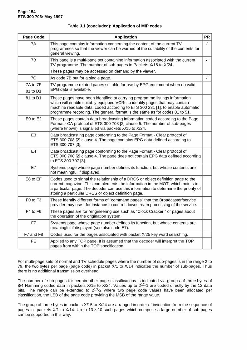
Page 154ETS 300 706: May 1997
Table J.1 (concluded): Application of MIP codes
Page Code Application PR
7A This page contains information concerning the content of the current TVprogrammes so that the viewer can be warned of the suitability of the contents forgeneral viewing.
9
7B This page is a multi-page set containing information associated with the currentTV programme. The number of sub-pages in Packets X/15 to X/24.
These pages may be accessed on demand by the viewer.
9
7C As code 7B but for a single page. 9
7A to 7F
81 to D1
TV programme related pages suitable for use by EPG equipment when no validEPG data is available.
81 to D1 These pages have been identified at carrying programme listings informationwhich will enable suitably equipped VCRs to identify pages that may containmachine readable data, coded according to ETS 300 231 [1], to enable automaticprogramme recording. The general format is the same as for codes 01 to 51.
E0 to E2 These pages contain data broadcasting information coded according to the PageFormat - CA protocol of ETS 300 708 [2] clause 5. The number of sub-pages(where known) is signalled via packets X/15 to X/24.
E3 Data broadcasting page conforming to the Page Format - Clear protocol ofETS 300 708 [2] clause 4. The page contains EPG data defined according toETS 300 707 [3].
E4 Data broadcasting page conforming to the Page Format - Clear protocol ofETS 300 708 [2] clause 4. The page does not contain EPG data defined accordingto ETS 300 707 [3].
E7 Systems page whose page number defines its function, but whose contents arenot meaningful if displayed.
E8 to EF Codes used to signal the relationship of a DRCS or object definition page to thecurrent magazine. This complements the information in the MOT, which points toa particular page. The decoder can use this information to determine the priority ofstoring a particular DRCS or object definition page.
F0 to F3 These identify different forms of "command pages" that the Broadcaster/serviceprovider may use - for instance to control downstream processing of the service.
F4 to F6 These pages are for "engineering use such as "Clock Cracker " or pages aboutthe operation of the origination system.
F7 Systems page whose page number defines its function, but whose contents aremeaningful if displayed (see also code E7).
F7 and F8 Codes used for the pages associated with packet X/25 key word searching.
FE Applied to any TOP page. It is assumed that the decoder will interpret the TOPpages from within the TOP specification.
For multi-page sets of normal and TV schedule pages where the number of sub-pages is in the range 2 to79, the two bytes per page (page code) in packet X/1 to X/14 indicates the number of sub-pages. Thusthere is no additional transmission overhead.
The number of sub-pages for certain other page classifications is indicated via groups of three bytes of8/4 Hamming coded data in packets X/15 to X/24. Values up to 212-1 are coded directly by the 12 databits. The range can be extended to 213-2 where two page code values have been allocated perclassification, the LSB of the page code providing the MSB of the range value.
The group of three bytes in packets X/15 to X/24 are arranged in order of invocation from the sequence ofpages in packets X/1 to X/14. Up to 13 × 10 such pages which comprise a large number of sub-pagescan be supported in this way.

Page 155ETS 300 706: May 1997
Annex K (informative): VCR programming and control via Teletext
ETS 300 231 [1] defines the use of Teletext data packets for the programming and control of domesticvideo recorders.
A method of labelling broadcast programmes is provided via the packets X/26 of Teletext pages listing TVprogramme schedules. This is based on a first announced transmission time for compatibility with otherservices. Simple programme selection with a cursor can be provided for the viewer by associatingmachine codes in the packets X/26 with the displayed items.
The Broadcast Service Data packet (8/30 Format 2) includes data identifying the origin of a broadcastprogramme, network identification and a programme label. The recording process can be controlledautomatically by comparing the programme labels of the requested programmes with the label for thecurrent programme. This allows the equipment to compensate for any changes in the transmissionschedule.

Page 156ETS 300 706: May 1997
Annex L (informative): Use of Teletext Data for Automatic Channel Installation
A protocol exists for a system which enables automatic installation of TVs and VCRs when connected to acable TV network. A unique Teletext page is part of the service delivered by the cable network operator.This contains machine-readable data giving the names of the channels provided and their transmissionfrequencies.
Details can be found in the document published by:
- EACEM / ECCA, Draft 2 (12th January 1994): "Automatic Channel Installation of TV and VCR via aUnique Teletext Page provided by a Cable Network Operator".
Page 157ETS 300 706: May 1997
Annex M (informative): Data transmission via Teletext
ETS 300 708 [2] defines the use of some of the Teletext packets presented in this ETS for thetransmission of non-specific data. There are two basic methods, each with the possibility of accesscontrol.
The first method carries the data within Teletext pages but the data is not always intended for directdisplay by conventional Teletext decoders. The pages used will normally be allocated hexadecimal pageaddresses and/or have the display inhibited.
The Page Format - Clear protocol does not include access control at the transport layer. The type of datato be broadcast depends on the application but it is likely to be displayed on domestic equipment followingprocessing within the decoder, possibly using presentation techniques defined in this ETS. Information onspecific applications is given in annex N.
In the Page Format - CA protocol the data for transmission can be scrambled at the transport layer toprovide access control for closed user groups or subscription user groups. The descrambling keys can beaddressed to individual users or groups of users by an "over air" addressing system, as can credit tokensfor "Pay per View" services. Both scrambling and addressing functions are of very high security andreliability. Complete blocks of data may be checked for accuracy using Cyclic Redundancy Check (CRC)words and these may also be used to provide error correction. The type of data to be broadcast dependson the application and, in general, it will not be intended for reception or display by domestic equipment.
The second data broadcasting method carries the data within Independent Data Lines (i.e. packets 30 and31) and is referred to by the abbreviation IDL. Such services are independent of any page based servicesin the same broadcast. Again, Conditional Access (CA) features can be incorporated.

Page 158ETS 300 706: May 1997
Annex N (informative): Data broadcasting services
N.1 Electronic Programme Guide (EPG)
ETS 300 707 [3] defines a protocol for an Electronic Programme Guide (EPG) using Teletext data packetsat the transport layer in accordance with the Page Format - Clear protocol of ETS 300 708 [2] clause 4.TV schedule information including transmission times, programme synopsis, ratings, themes, etc., isdownloaded as machine readable data. The publisher of the information can define this own on-screenmenu structure and navigation protocol to be adopted by suitable decoders. The availability of theschedule data and transmission bandwidth determines the number of channels covered and number ofprogrammes included.
To a large extent the performance and features offered by decoding equipment is at the manufacturer'sdiscretion. Typical features might included sorting multi-channel programme information by time-slot,channel or themes chosen by the viewer. Presentation aspects are compatible with those described in thisETS although the manufacturer can chose to use any suitable method.
In the absence of any EPG data, a decoder may find the information carried by the Magazine InventoryPage (MIP) useful in providing a default mode of operation based on the TV schedule pages in the normalTeletext service.

Page 159ETS 300 706: May 1997
Annex O (informative): Relationship to earlier specifications
This ETS together with ETS 300 708 [2] replace fully the EBU document "Teletext Specification for625-line television systems", SPB492, December 1992. This ETS covers the fundamentals of Teletext andpresentation-related aspects. ETS 300 708 [2] deals with the application of Teletext in the databroadcasting environment.
Certain items described in SPB492 have been omitted where it is known that they have never beenimplemented or where they are fully covered by a revised method or modified coding contained in the newspecifications.

Page 160ETS 300 706: May 1997
Annex P (informative): Non-Teletext signals in the VBI
TV lines 6-22 and 318-335 may be used for test signals, noise measurements, encryption and otherinformation services as well as Teletext. Some existing signals, for example Videocrypt, can beinterpreted as valid Teletext by some existing decoders under some circumstances, resulting in corrupteddisplays.
It is desirable that any new signals are constructed and transmitted to have no effect on Teletextdecoders. This may be achieved by ensuring that there is no part of the waveform which a Teletextdecoder might interpret as a valid framing code especially in the presence of noise. It should be noted thatsome existing decoders will accept a single bit error in the framing code and have a framing codeacceptance window which is considerably wider than the transmission limits defined in this specification.
Teletext decoders should be designed to be insensitive to non-Teletext waveforms.
It is not reasonable to assume that the type of waveform on a given line on any channel will remainconstant.
Further details of the signals likely to be encountered in the VBI can be found in TR 101 233 [7].

Page 161ETS 300 706: May 1997
Annex Q (informative): Bibliography
- Institut für Rundfuntechnik, ARD/ZDF Technical Guidelines, No. 8 R 5, 2nd Edition(2nd December 1991): "TOP" System for Teletext".
- EACEM / ECCA, Draft 2 (12 January 1994): "Automatic Channel Installation of TV and VCR via aUnique Teletext Page provided by a Cable Network Operator".
- EBU SPB492 (December 1992): "Teletext Specification for 625-line television systems".

Page 162ETS 300 706: May 1997
History
Document history
November 1996 Unified Approval Procedure UAP 57: 1996-11-04 to 1997-02-28
May 1997 First Edition
ISBN 2-7437-1488-3Dépôt légal : Mai