enhanced shaft alignment - ww2.eagle.org · in the shaft alignment sighting, the global reference...
TRANSCRIPT

G u i d e f o r E n h a n c e d S h a f t A l i g n m e n t
GUIDE FOR
ENHANCED SHAFT ALIGNMENT
DECEMBER 2018
American Bureau of Shipping Incorporated by Act of Legislature of the State of New York 1862
2018 American Bureau of Shipping. All rights reserved. 1701 City Plaza Drive Spring, TX 77389 USA
F o r e w o r d
Foreword This Guide for Enhanced Shaft Alignment provides direction to owners and operators who wish to perform a more detailed shaft alignment analysis and installation assessment.
Vessels designed, constructed and operated in compliance with the requirements of this Guide may be assigned the Class Notation ESA or ESA+
Assignment of the ESA Notation requires the review of plans and calculations by an ABS Engineering Office in accordance to the ABS Guide for Enhanced Shaft Alignment.
Assignment of the ESA+ Notation requires the review of plans and calculations by an ABS Engineering Office and compliance with the installation, measurements and sea trials requirements, in accordance to this Guide. In addition, the ESA+ Notation requires the attendance of an ABS Surveyor (during additional shafting alignment efforts) during the shaft alignment works which are in addition to regular Rule requirements, as explained in this Guide.
The intention of the Guide is to address shafting arrangements, such as installations with no forward stern tube bearing that may particularly benefit from a more detailed analysis and a more accurate and structured procedure so as to optimize the shaft alignment and improve the service life of the vessel’s powertrain. This Guide is intended to apply mainly to shaft alignment-sensitive vessels, although it could apply to a wider range of powertrains including geared installations.
The main aspects that distinguish compliance with these Notations from the standard Rule application are:
• For the ESA Notation assignment:
1. Shaft alignment optimization calculations are required.
2. Compulsory inclusion of hull deflections to be taken into account in the analysis.
3. Compulsory inclusion of propeller loads to be taken into account in the analysis.
4. Requirement for lateral vibration (whirling) analysis of the powertrain shafting systemin accordance with 2/1.3.5 of this Guide.
5. The vessel must be assigned the TCM (Tailshaft Condition Monitoring) Notation.
• For the ESA+ Notation assignment:
In addition to the above:
6. Final sighting is to be conducted after the engine or gearbox and other heavy machinery is installed on board, with superstructure in place, and all major steel works completed at the aft part of the vessel.
7. Shaft alignment verification at more than one service condition.
8. Sea trials procedures and recordings
The ABS Guide for Enhanced Shaft Alignment is to be used in conjunction with all other applicable ABS Rules, Guides and Guidelines.
This Guide becomes effective on the first day of the month of publication.
Users are advised to check periodically on the ABS website www.eagle.org to verify that this version of this Guide is the most current.
We welcome your feedback. Comments or suggestions can be sent electronically by email to [email protected].
ii ABS GUIDE FOR ENHANCED SHAFT ALIGNMENT . 2018

T a b l e o f C o n t e n t s
GUIDE FOR
ENHANCED SHAFT ALIGNMENT
CONTENTS SECTION 1 General .................................................................................................... 1
1 Introduction ......................................................................................... 1 1.1 ESA or ESA+ Notation .................................................................... 1 1.3 Definitions ........................................................................................ 2
3 Application .......................................................................................... 4 3.1 General............................................................................................ 4
5 Documentation .................................................................................... 5 5.1 Documentation to be Submitted (Applicable for the ESA and
ESA+ Notations) .............................................................................. 5 TABLE 1 Propulsion Types and Shaft Alignment Systems that can be
Covered by the ESA Notation ................................................... 5 TABLE 2 Hydrodynamic Propeller Loads Based on Results from CFD
Database ................................................................................... 6 FIGURE 1 Selected Differences between ESA Notation Requirements
and ABS Rules .......................................................................... 1 FIGURE 2 Schematic Illustrating the Misalignment Angle ......................... 3 FIGURE 3 Stern of Vessel (with the rudder and propeller fitted) and
Coordinate System for the Calculation of Propeller Loads ....... 6 SECTION 2 Calculation Requirements for ESA and ESA+ Notations .................... 8
1 Calculations ........................................................................................ 8 1.1 General............................................................................................ 8 1.3 Additional Specialized Calculations ................................................. 8
3 Hull Girder Deflections ...................................................................... 13 3.1 General.......................................................................................... 13
FIGURE 1 Schematic Showing the Requirement of the Gearbox Forces
Calculation in the Shaft Alignment Analysis Report................. 9 FIGURE 2 Stern Tube Bearing Contact Analysis Screenshots from the
ABS Shaft Alignment Software ............................................... 10 FIGURE 3 Stern Tube Bearing Contact Analysis Screenshots from
Optimized Double Slope Design from Dry and FSI FEA Models ..................................................................................... 11
FIGURE 4 Representation of Critical Speeds for a Whirling Calculation using a Campbell Diagram ...................................................... 12
ABS GUIDE FOR ENHANCED SHAFT ALIGNMENT . 2018 iii

FIGURE 5 Screenshot from the ABS Shaft Alignment Software Showing Typical Data Required for Fast Determination of Hull Deflection for Shaft Alignment Optimization Analysis ............. 13
FIGURE 6 Typical Finite Element Model for the Purposes of Hull Deflection Calculations ........................................................... 14
SECTION 3 Alignment Procedure Applicable Only for the ESA+ Notation ......... 15
1 General Requirements ...................................................................... 15 1.1 Major Stages ................................................................................. 15
3 Shaft Alignment Installation Procedure ............................................. 15 3.1 Conditions ...................................................................................... 15 3.3 Means of Bearing Reaction Measurement and Verification ........... 16 3.5 Recordings .................................................................................... 16
FIGURE 1 Bearing Reaction Values During Sea Trials for Different
Vessel Conditions for the Forward Stern tube Bearing (FWD), the Intermediate Bearing (IB) and the Aftmost Main Engine Bearings (ME) .................................................... 17
FIGURE 2 Correlation Between Measured and Calculated Bearing Reaction Values for a Specific Vessel Condition .................... 17
SECTION 4 Sea Trials Applicable Only for the ESA+ Notation ............................ 18
1 General Requirements ...................................................................... 18 1.1 Test Procedure .............................................................................. 18 1.3 Bearing Run-in Process ................................................................. 19 1.5 Sea Trials for Shaft Alignment ....................................................... 19 1.7 Jack-up Tests During Sea Trials .................................................... 19
FIGURE 1 Bearing Temperatures Monitored During Acceptance Sea
Trials ....................................................................................... 18 SECTION 5 Maintenance of ESA and ESA+ Notations .......................................... 20
1 Modifications ..................................................................................... 20 SECTION 6 Surveys Applicable Only for the ESA+ Notation ............................... 21
1 Initial Survey...................................................................................... 21 3 Surveys after Construction ................................................................ 21
APPENDIX 1 Definitions of Shaft Alignment Optimization ..................................... 22
1 Shaft Alignment Optimization Alternative Definitions ....................... 22 FIGURE 1 2D Design Optimization Mathematical Concept ..................... 22 FIGURE 2 3D and higher Design Optimization Mathematical Concept ... 23
APPENDIX 2 References ............................................................................................ 24
iv ABS GUIDE FOR ENHANCED SHAFT ALIGNMENT . 2018
S e c t i o n 1 : G e n e r a l
S E C T I O N 1 General
1 Introduction
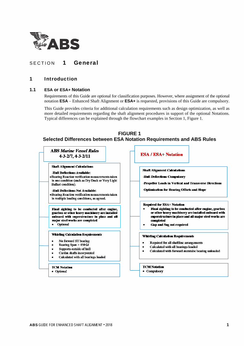
1.1 ESA or ESA+ Notation Requirements of this Guide are optional for classification purposes. However, where assignment of the optional notation ESA – Enhanced Shaft Alignment or ESA+ is requested, provisions of this Guide are compulsory.
This Guide provides criteria for additional calculation requirements such as design optimization, as well as more detailed requirements regarding the shaft alignment procedures in support of the optional Notations. Typical differences can be explained through the flowchart examples in Section 1, Figure 1.
FIGURE 1 Selected Differences between ESA Notation Requirements and ABS Rules
ABS GUIDE FOR ENHANCED SHAFT ALIGNMENT . 2018 1

Section 1 General
1.1.1 Objective The objective of this Guide is to identify additional requirements and procedures beyond the minimum requirements currently specified in the ABS Marine Vessel Rules, so as to further enhance the shaft alignment to make it more robust and less susceptible to unaccounted disturbances or errors in production. Vessels designed, constructed and operated in compliance with the requirements of this Guide may be assigned the Class Notation ESA or ESA+.
1.1.2 General Requirements The shaft alignment procedure for vessels with the ESA+ notation requires that the final shaft alignment sighting be carried out after the vessel stern blocks are fully welded and all of the heavy stern structure is in place, such as any stern accommodation block, including the main engine and/or gearbox. This is to be verified by the attending Surveyor.
1.3 Definitions 1.3.1 ABS Rules
In this document the ABS Rules for Building and Classing Marine Vessels are hereafter referred to as “Marine Vessel Rules”.
1.3.2 ESA or ESA+ Notation The Notation ESA or ESA+ is granted based upon compliance with the requirements described in this Guide.
The ESA Notation requires compliance with the calculation related sections of this Guide, described in Sections 1 and 2. The additional shaft alignment installation and measurement related requirements, described in this Guide are not applicable for the ESA Notation and instead, the pertinent requirements in 4-3-2/11 of the Marine Vessel Rules apply.
The ESA+ Notation requires compliance with all the sections of this Guide including the installation procedures and sea trial measurement requirements as well as maintenance and survey requirements.
1.3.3 FEA, FSI, CFD FEA: Finite Element Analysis
FSI: Fluid Structure Interaction
CFD: Computational Fluid Dynamics
1.3.4 MCR Maximum Continuous Rating
1.3.5 Very Light Ballast Condition The condition in which the vessel is either in dry-dock or afloat at a quay with minimum ballast nearing a “lightship” condition. This condition is expected to have the least amount of influence in hull deflections that would affect the shaft alignment. Therefore, it is considered as a condition without hull deflections.
1.3.6 Global Reference Line In the shaft alignment sighting, the global reference line is the 0 (zero) datum line used as the reference for all bearing offsets. All bearing offset values are recorded based on this datum. The Guide does not impose a specific or unique reference line to be used. Consideration is to be given when applying offsets in installations where different reference lines are used in the alignment analysis and in the sighting related measurements.
1.3.7 Shaft Alignment The configuration of the shafts and bearings relative to the centerlines of the bearings from the theoretical straight-line condition, so as to achieve an acceptable bearing load distribution and shaft-bearing misalignment angles.
2 ABS GUIDE FOR ENHANCED SHAFT ALIGNMENT . 2018

Section 1 General
1.3.8 Alignment Optimization Alignment optimization is a condition where a mathematically predicted set of bearing offsets produces a satisfactory bearing load distribution for more than one alignment condition.
The shaft alignment optimization estimates the most possible uniform bearing load distribution for any given vessel loading case. It will produce an optimum set of bearing offsets, which when applied in the dry dock or at the light ship draft condition will satisfy the bearing loading conditions in all service drafts of the vessel (e.g., from ballast to fully-laden).
Knowing the hull deflections envelope together with the required operating conditions (e.g. fully loaded, hot dynamic, including propeller loads), a bearing offsets range can be defined within which a bearing load distribution is found acceptable.
This set of bearing offsets is said to be optimal and the shaftline is said to be optimum for alignment purposes, in accordance to the definition given to the alignment optimization.
Performing a reverse engineering calculation with the desired bearing load distribution as an input, a set of bearing offsets can be defined as an output. Thus, the reverse calculation can be used as a confirmatory process in bearing offset validation.
1.3.9 Campbell Diagram A Campbell diagram is a means of vibration data presentation, where a system’s natural frequencies (Eigen frequencies) are plotted against its operational regime and in this case the shaftline’s natural frequencies against the shaftline’s rotational speeds of operation; see Section 2, Figure 3.
1.3.10 Misalignment Angle The angle between the shaft centerline and the bearing center-line, as shown in the schematic of Section 2, Figure 2.
FIGURE 2 Schematic Illustrating the Misalignment Angle
1.3.11 TCM ABS Tailshaft Condition Monitoring Notation.
1.3.12 Shaft Alignment Sensitive Vessels Large tank vessels such as Suezmax, VLCC, ULCC, LNGC, large bulk carriers, such as Capesize and VLOC, and large container vessels, (i.e., above 9000 TEU) are considered to be shaft alignment-sensitive vessels due to their typical hull deflection profiles.
In addition, the following propulsion systems are considered to be potential shaft alignment-sensitive installations:
Propeller side
Engine side
Relative misalignment angle
ABS GUIDE FOR ENHANCED SHAFT ALIGNMENT . 2018 3

Section 1 General
• Directly driven propeller installations
• Low speed diesel installations
• Systems with relatively short and rigid shafting and a relatively flexible hull structure
• Vessels with twin screw installations
• No forward stern tube bearing installations
1.3.13 Similar Vessels for Hull Deflection Purposes Hull deflections can be estimated by finite element calculations or by measurements from similar vessels (same type, similar vessel size, similar double bottom height in the area of the engine room, similar stern tube and stern arrangement) or other recognized or benchmarked calculation methodologies.
3 Application
3.1 General 3.1.1 Notation Assignment
While the notation has been developed primarily for shaft alignment sensitive vessels and propulsion systems, other types of vessels and other types of powertrains may be granted the ESA or ESA+ Notation.
3.1.2 Survey (Applicable only for the ESA+ requirements) The Surveyor is to attend all stages of alignment as described herein.
As a minimum, the shipyard is to produce a log recording all the shaft alignment installation steps, including the sighting data records, bearing slope verification, clearance measurement, and bearing reactions along with the manufacturers’ acceptance criteria. The same is to be submitted to the ABS Engineering Office for review and for future reference. In particular, sighting data records, bearing slope verification and clearance measurements are to be verified by the attending Surveyor.
3.1.3 Correlation with Calculations (Applicable for the ESA and ESA+ requirements) The onboard shaft alignment is to be consistent with the system description and input parameters as listed in the ABS reviewed calculations. Correlation between measurements and calculations for various shaft alignment conditions is to be verified at all stages of the process.
3.1.4 Other Powertrains The Class Notation ESA or ESA+ is not applicable to ships equipped with azimuthal thrusters or nonconventional shaft lines intended for main propulsion, or as otherwise deemed inappropriate by ABS.
3.1.5 Applicability Requirements Class Notation ESA or ESA+ may be assigned to ships designed with one or more propulsion shaft lines that comply with the following:
i) Propulsion types of direct drives and geared drive installations, as shown in Section 1, Table 1.
ii) The additional calculation requirements found in Subsection 2/1, including hull deflections and shaft alignment optimization.
iii) The shaft alignment processes described in Section 3 of this Guide for ESA+.
iv) Possess the TCM Notation as per 4-3-2/13 of the Marine Vessel Rules.
3.1.6 Geared Installations For geared installations, only the propeller to gearbox shaft alignment is required to be submitted to ABS for review.
4 ABS GUIDE FOR ENHANCED SHAFT ALIGNMENT . 2018

Section 1 General
3.1.7 Alternative Shafting Arrangements Shafting arrangements applicable for the ESA or ESA+ Notation are shown in Section 1, Table 1 below.
In cases of specific shafting arrangements not covered by this Guide, ABS may require additional calculations to verify compliance with the ESA or ESA+ Notation requirements.
TABLE 1 Propulsion Types and Shaft Alignment Systems
that can be Covered by the ESA Notation Propulsion Type Prime Mover Alignment System
Direct drive installation Low-speed diesel/gas engine From propeller to crankshaft
Electric motor From propeller to rotor shaft
Geared drive installation Medium-speed diesel/gas engine
From propeller to main gear output shaft Steam/gas turbine
Electric motor
5 Documentation
5.1 Documentation to be Submitted (Applicable for the ESA and ESA+ Notations) 5.1.1 Drawings
i) Shafting arrangement
ii) Intermediate shaft, propeller shaft drawings
iii) Couplings – integral, demountable, keyed, or shrink-fit, coupling bolts and keys’ drawings
iv) Shaft bearing drawings
v) Shaft seals’ drawings
vi) Propeller drawings
vii) Gearbox drawings, as applicable
viii) Stern tube bearing and intermediate bearing drawings
5.1.2 Data i) Rated power of main engine and shaft rpm
ii) Allowable bearing loads
iii) Propeller mass and inertia
iv) Hull deflections data for ballast and fully laden condition at the bearing points of support positions. Hull deflections are to be analyzed with the aft peak tanks full or as full as applicable, in accordance to the vessel’s loading manual.
v) Bending moment and shear force values at the thrust shaft flange of the main engine (static condition)
vi) Bearing stiffness values, bearing clearances, lubricant properties and maximum allowed bearing load
vii) For geared installations, gear forces and moments
ABS GUIDE FOR ENHANCED SHAFT ALIGNMENT . 2018 5

Section 1 General
viii) Hydrodynamic propeller loads (forces and moments) for the following conditions:
a) Straight course, at full speed, in a fully laden condition
b) Straight course, at full speed, in the ballast condition
c) Full rudder starboard and port turns, at full speed, in a fully laden condition
d) Full rudder starboard and port turns, at full speed, in the ballast condition
Transverse and Vertical Hydrodynamic propeller loads are to be used. These can be estimated by calculations (lifting surface method, boundary panel method, CFD, etc.) or based on empirical/database formulae.
In case that hydrodynamic propeller loads are not available, then empirical formulae are to be used for the running condition calculations as shown in the following table.
A turning condition is hereby defined as the condition in which the vessel is performing a steady state full rudder turn to port or starboard, commencing from a straight course at a ballast or full scantling draft at MCR condition.
TABLE 2
Hydrodynamic Propeller Loads Based on Results from CFD Database Straight Ahead Condition Turning Condition
For single screw vessel –5% of Q +30% of Q
–30% of Q
For twin screw vessel ±20% of Q –30% of Q
where
Q = torque at MCR
Positive sign (+) implies upward moment about the transverse axis
Negative sign (–) implies downward moment about the transverse axis
FIGURE 3 Stern of Vessel (with the rudder and propeller fitted) and Coordinate System
for the Calculation of Propeller Loads
6 ABS GUIDE FOR ENHANCED SHAFT ALIGNMENT . 2018

Section 1 General
5.1.3 Calculations i) Details of shaft alignment calculation as required by 4-3-2/7.3.2 of the Marine Vessel Rules
ii) Details of shaft alignment optimization calculation
iii) Aft Stern Tube Bearing Contact Analysis detailing the maximum remaining misalignment angle between the shaft and the bearing, as well as the maximum estimated contact area, contact pressure, and the lubricant film thickness, considering the conditions described in 2/1.1 of this Guide.
iv) Lateral Vibration (Whirling) Calculations
5.1.4 Materials i) Material properties of the shafts and bearings
5.1.5 Procedures (Applicable only for the ESA+ requirements) i) Details of shaft alignment procedure.
ii) Details of bearing run-in procedure.
5.1.6 Measurements (Applicable only for the ESA+ requirements) i) Bearing temperature measurements and recording during run-in phase before sea trials
ii) Shaft Alignment Measurements including jack-up tests or strain gauge recordings
iii) Measurement report as per the Guide requirements found in 4/1.1
ABS may require additional calculations, drawings or documentation, as deemed necessary.
ABS may require justification of the theoretical basis of any simplified approach utilized in submitted analysis, as well as the origin and methods used to obtain any empirical data used.
ABS GUIDE FOR ENHANCED SHAFT ALIGNMENT . 2018 7
S e c t i o n 2 : C a l c u l a t i o n R e q u i r e m e n t s f o r E S A a n d E S A + N o t a t i o n s
S E C T I O N 2 Calculation Requirements for ESA and ESA+ Notations
1 Calculations
1.1 General 1.1.1 Scope and Objective of Shaft Alignment Calculations
The goal of shaft alignment calculations is to provide data to the shipyard production personnel to determine satisfactory alignment under all intended operating conditions of the vessel (from ballast to full-load). It is recognized that a fully ballasted vessel or a fully loaded vessel may produce different bearing reaction results when the aft peak tank(s) is full or empty and when the aft peak tanks are not void spaces.
When a hull deflection analysis such as FEA enables an accurate differentiation between hull deflections with a full or empty aft peak, the calculations listed below are to assess the influence of the resulting localized hull deflections onto the bearing loads. The assessment is to be conducted for an empty aft peak tank and for a full aft peak or an aft peak tank filled to the maximum level as defined in the vessels’ loading manual:
i) Dry dock or afloat at very light ballast or lightship condition with cold engine and with propeller partially immersed.
ii) Fully-ballasted vessel with hot engine and propeller fully immersed in static condition.
iii) Fully-ballasted vessel with hot engine and propeller fully immersed in dynamic running condition including a simulation of a straight ahead run and full port and starboard turns as defined in 1/5.1.2 of this Guide.
iv) Fully-laden vessel with hot engine and propeller fully immersed in static condition.
v) Fully-laden vessel with hot engine and propeller fully immersed in dynamic running condition including a simulation of a straight ahead run, and vessel full port and starboard turns turning simulation (i.e., straight, port and starboard) with propeller hydrodynamic loads, as defined in 1/5.1.2 of this Guide.
1.3 Additional Specialized Calculations 1.3.1 Requirements
All the design and installation criteria for shaft alignment calculations as described in the Marine Vessel Rules are to be applied.
Additional calculation requirements to those specified in 4-3-2/7.3.2 of the Marine Vessel Rules are:
1.3.1(a) Optimization of Bearing Offsets
i) Define bearing offsets optimization as outlined in 2/1.3.2 and Appendix 1 of this Guide.
ii) If the optimization is not defined as per the ABS definition, a clear definition of the proposed objective function of the optimization, as well as the design and state variables used in the proposed optimization analysis, is to be submitted to ABS for special consideration.
8 ABS GUIDE FOR ENHANCED SHAFT ALIGNMENT . 2018
Section 2 Calculation Requirements for the ESA and ESA+ Notations
1.3.1(b) Aft Stern Tube Bearing Contact Analysis: Modelling techniques, such as bearing multi-point of support or 3D finite element modelling with fluid structure interaction between the bearing, the oil film and the rotating shaft can be acceptable, provided appropriate assumptions and recognized engineering practices are demonstrated in the submitted calculation report.
1.3.1(c) Lateral Vibration (Whirling) Calculations: The requirements for whirling vibration calculations, as addressed in 4-3-2/7.9.2 of the Marine Vessel Rules, are to be applied. For the ESA or ESA+ Notation, the whirling vibration calculation is to be submitted for all cases, even if not required by 4-3-2/7.9.1 of the Marine Vessel Rules.
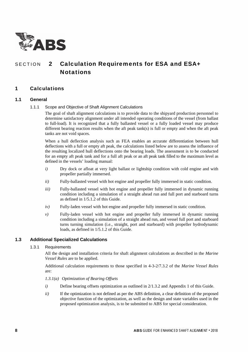
1.3.1(d) Geared Installation Calculations. For shafting driven via a gearbox, the alignment analysis is to take into account the total dynamic forces exerted by the pinion on the gear. Moments due to unbalanced axial components of tooth force of single helical gears, illustrated in Section 2, Figure 1, are to be included in the calculations.
FIGURE 1 Schematic Showing the Requirement of the Gearbox Forces Calculation
in the Shaft Alignment Analysis Report Helix Angle
Tooth Force
Intermediate Shaft
Forward Bearing (highest dynamic load)
Aft Bearing
Gearbox Main Wheel
Axial
Radial
1.3.2 Shaft Alignment Optimization Calculation The Shaft Alignment Optimization Calculation is to provide a set of bearing offsets at the drydock or very light ballast condition that result in optimum bearing reactions over the full range of vessel loading conditions as described in 2/1.1.1.
The ABS definition of Shaft Alignment Optimization and Alternative Shaft Alignment Optimization is outlined in Appendix 1 of this Guide and is fully integrated into the ABS Shaft Alignment software.
ABS Shaft Alignment software offers an efficient way to perform the shaft alignment optimization calculation. This program can be made available to ABS clients. Interested parties may contact the nearest ABS engineering office for further information. Calculations based on alternative software programs utilizing alternative shaft alignment optimization definitions can be also acceptable.
Moment
ABS GUIDE FOR ENHANCED SHAFT ALIGNMENT . 2018 9

Section 2 Calculation Requirements for the ESA and ESA+ Notations
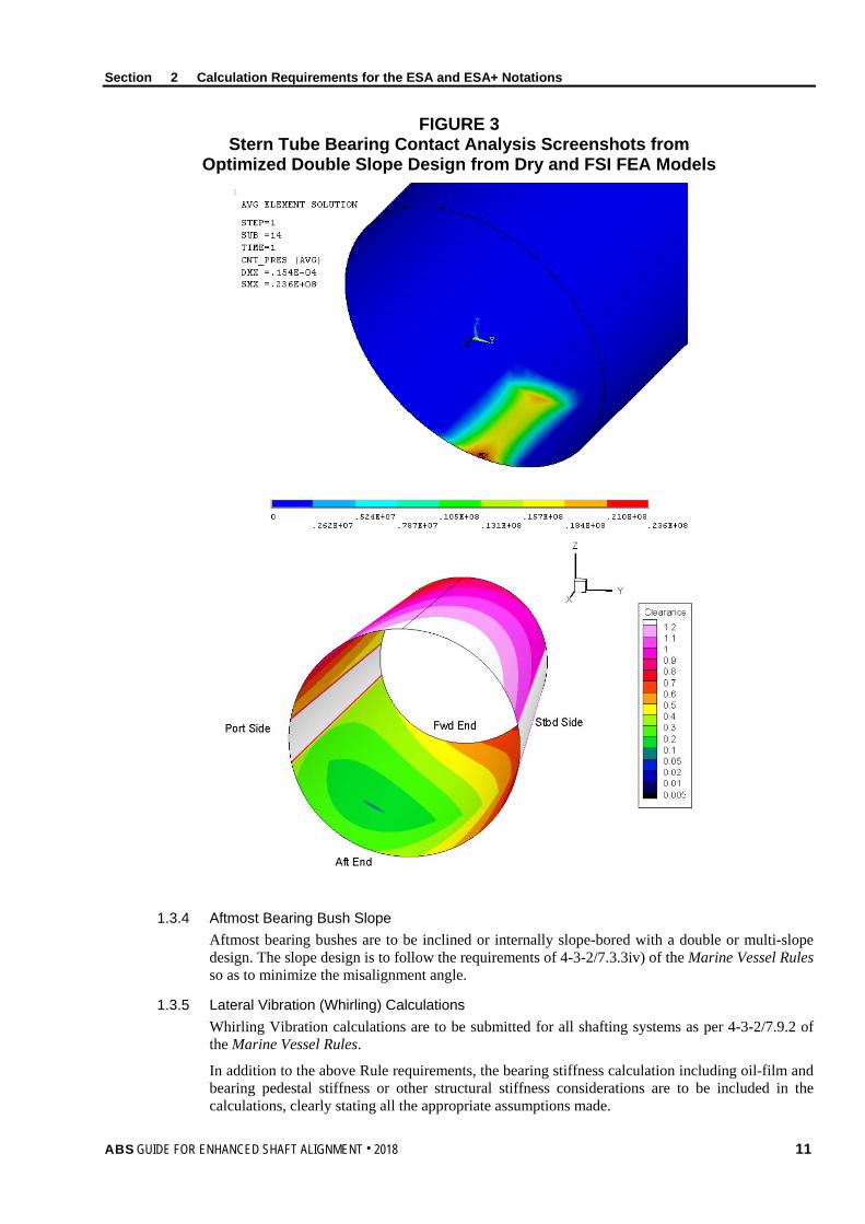
1.3.3 Aft Stern Tube Bearing Contact Analysis The misalignment angle between the propeller shaft and the aftmost bearing bush, either stern tube or strut, is not to exceed 0.3mm/m or 0.3 mrad under all analyzed conditions, when a single point of support is utilized for the bearing model. The axial position of the single point of support may vary and it is to be appropriately evaluated for each shaft alignment condition presented. When a 3D finite element model with fluid structure interaction between the bearing, the oil film and the rotating shaft is utilized, the misalignment angle criterion can be substituted by an oil film thickness criterion, such that the oil film thickness may not be below 30 μm for all analyzed conditions. The ABS Shaft Alignment Optimization software may also be used in the required bearing contact investigation and analysis; see Section 2, Figures 2 and 3.
FIGURE 2 Stern Tube Bearing Contact Analysis Screenshots from
the ABS Shaft Alignment Software
10 ABS GUIDE FOR ENHANCED SHAFT ALIGNMENT . 2018
Section 2 Calculation Requirements for the ESA and ESA+ Notations
FIGURE 3 Stern Tube Bearing Contact Analysis Screenshots from
Optimized Double Slope Design from Dry and FSI FEA Models
1.3.4 Aftmost Bearing Bush Slope Aftmost bearing bushes are to be inclined or internally slope-bored with a double or multi-slope design. The slope design is to follow the requirements of 4-3-2/7.3.3iv) of the Marine Vessel Rules so as to minimize the misalignment angle.
1.3.5 Lateral Vibration (Whirling) Calculations Whirling Vibration calculations are to be submitted for all shafting systems as per 4-3-2/7.9.2 of the Marine Vessel Rules.
In addition to the above Rule requirements, the bearing stiffness calculation including oil-film and bearing pedestal stiffness or other structural stiffness considerations are to be included in the calculations, clearly stating all the appropriate assumptions made.
ABS GUIDE FOR ENHANCED SHAFT ALIGNMENT . 2018 11

Section 2 Calculation Requirements for the ESA and ESA+ Notations
The following is to be examined in terms of calculating critical speed locations within the operational speed range:
i) All bearings are positively loaded per the alignment calculation report results, while applying the appropriate bearing stiffness for each bearing.
ii) Same as 2/1.3.5i), but with an unloaded forward stern tube bearing.
The critical speeds for 2/1.3.5i) and 2/1.3.5ii) are not to lie within ±20% of the main engine MCR.
The preferred means of critical speed presentation for lateral-whirling vibration is through a Campbell diagram, with the X-axis representing the propeller shaft speed and the Y-axis representing the natural frequency variation with propeller shaft speed. The influence of the gyroscopic effect is to be considered and possibly demonstrated in the Campbell diagram. The significant forcing orders, the first order (shaft unbalance) and the blade passing frequency (e.g., fourth or fifth order for a five-bladed propeller) is to be overlaid on the graph and clearly show the critical speeds as intersections between the forcing orders and the natural frequency lines. The critical speeds are to be listed in RPM, preferably in a tabular format. Those that lie inside the operating speed range are to be distinctly highlighted.
FIGURE 4 Representation of Critical Speeds for a Whirling Calculation
using a Campbell Diagram
12 ABS GUIDE FOR ENHANCED SHAFT ALIGNMENT . 2018
Section 2 Calculation Requirements for the ESA and ESA+ Notations
3 Hull Girder Deflections
3.1 General 3.1.1 Hull Deflection Calculation
The effects of hull deflections for the ballast and the fully laden conditions can be established by utilizing specialized computer programs and methodologies, such as the finite element model method. Hull deflections are to be obtained at each bearing supporting point, including at the main engine bearings. The set of hull deflections may be provided using either an absolute coordinate system or as relative displacement values through a transformation based on a reference line defined by the aft most stern tube bearing and the most forward bearing of the shaft line including the engine, gearbox or any other prime mover machinery.
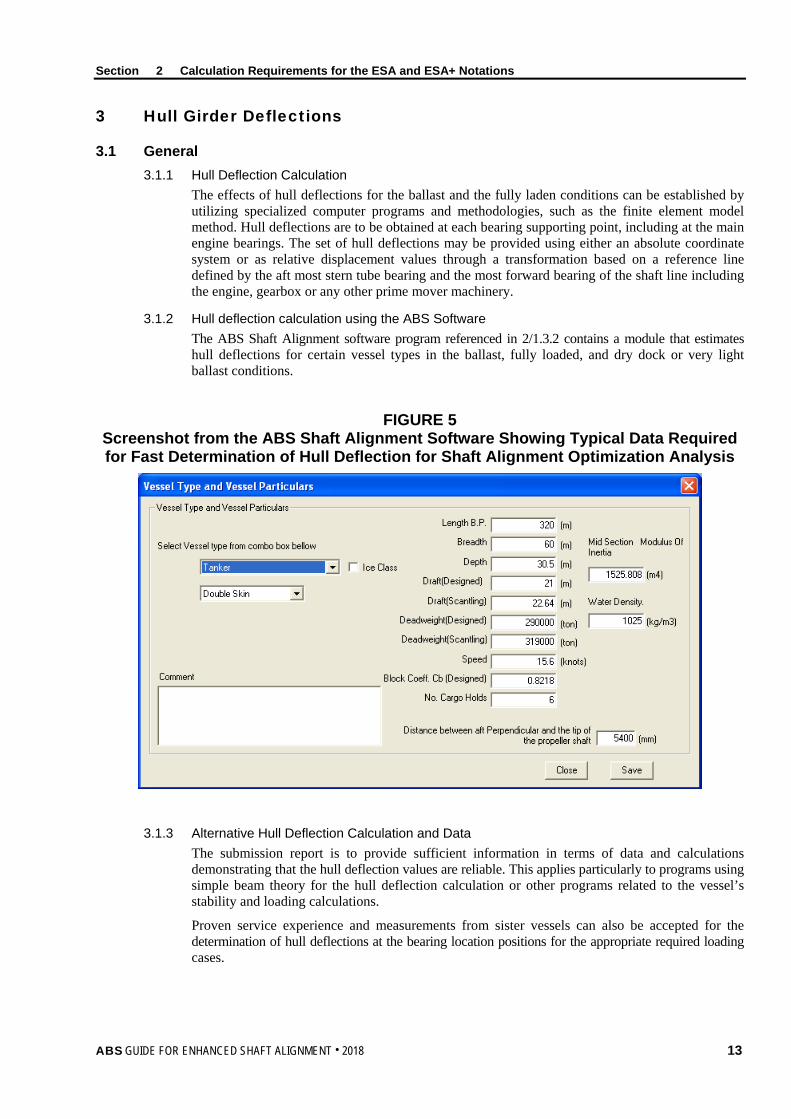
3.1.2 Hull deflection calculation using the ABS Software The ABS Shaft Alignment software program referenced in 2/1.3.2 contains a module that estimates hull deflections for certain vessel types in the ballast, fully loaded, and dry dock or very light ballast conditions.
FIGURE 5 Screenshot from the ABS Shaft Alignment Software Showing Typical Data Required for Fast Determination of Hull Deflection for Shaft Alignment Optimization Analysis
3.1.3 Alternative Hull Deflection Calculation and Data The submission report is to provide sufficient information in terms of data and calculations demonstrating that the hull deflection values are reliable. This applies particularly to programs using simple beam theory for the hull deflection calculation or other programs related to the vessel’s stability and loading calculations.
Proven service experience and measurements from sister vessels can also be accepted for the determination of hull deflections at the bearing location positions for the appropriate required loading cases.
ABS GUIDE FOR ENHANCED SHAFT ALIGNMENT . 2018 13

Section 2 Calculation Requirements for the ESA and ESA+ Notations
For cases where the finite element (FE) method is performed, the model is to include all structural parts and all steelwork of the engine room and the double bottom. Where an FE model is constructed, a reference to any modeling procedures such as element types, ratios of element sizes, material properties, elements warping ratio limits, etc., is to be included in the report.
In certain cases, ABS may request electronic submission of the actual FE model used for the hull deflection modeling.
FIGURE 6 Typical Finite Element Model for the Purposes of Hull Deflection Calculations
14 ABS GUIDE FOR ENHANCED SHAFT ALIGNMENT . 2018
S e c t i o n 3 : A l i g n m e n t P r o c e d u r e A p p l i c a b l e O n l y f o r t h e E S A + N o t a t i o n
S E C T I O N 3 Alignment Procedure Applicable Only for the ESA+ Notation
1 General Requirements
1.1 Major Stages The shaft alignment procedural steps are similar to those described in the requirements found in 4-3-2/7.3.4 and 4-3-2/11.1 of the Marine Vessel Rules and in the ABS Guidance Notes on Propulsion Shafting Alignment. Further details for each of the following measurements may be found in those Guidance Notes:
• Sighting through (bore sighting)
• Engine bedplate pre-sagging
• Reactions measurements
• Shaft eccentricity (run-out) verification
• Intermediate shaft bearing offset readjustment
• Crankshaft deflection measurements
• Engine bedplate deflections measurement
• Gear contact evaluation
• Gear-shaft bearings reaction measurements
3 Shaft Alignment Installation Procedure
3.1 Conditions In addition to the requirements in 4-3-2/7.3.4 and 4-3-2/11.1 of the Marine Vessel Rules, the following are to apply: The Shipyard is to produce a log with the recordings of all the shaft alignment installation steps, including sighting data recorded and this log is to be submitted to the ABS Engineering office for verification against approved limits or tolerances.
i) The final bearing sighting is not to commence before the vessel stern blocks are fully welded and all of the heavy stern structure is in place including the main engine.
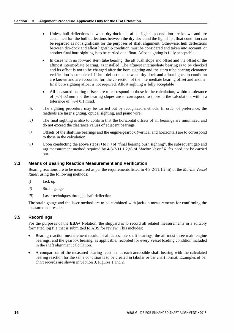
ii) The final bearing sighting is to extend from the aftermost bearing, (stern tube or strut, as applicable), up to the engine or gearbox output flange, and is to be used to adjust the relative position between engine/gearbox and the stern tube bearing offsets. Intermediate bearing offsets may be adjusted by the final sighting. The final bearing bush sighting is to verify the following conditions:
• The aft and forward bush slope(s) and offset, as-installed. The measurements are to be taken in respect of reference line, in at least three longitudinal positions in the aft bush; for multiple slope aft bush, the minimum number of measuring positions is to be multiplied by the number of slopes. For example, for a double sloped bush, the measurements are to be taken in at least six positions in the aft bush. The positions need to include the knuckle point or transition point positions between the slopes.
ABS GUIDE FOR ENHANCED SHAFT ALIGNMENT . 2018 15
Section 3 Alignment Procedure Applicable Only for the ESA+ Notation
• Unless hull deflections between dry-dock and afloat lightship condition are known and are accounted for, the hull deflections between the dry dock and the lightship afloat condition can be regarded as not significant for the purposes of shaft alignment. Otherwise, hull deflections between dry-dock and afloat lightship condition must be considered and taken into account, or another final bore sighting is to be carried out afloat. Afloat sighting is fully acceptable.
• In cases with no forward stern tube bearing, the aft bush slope and offset and the offset of the aftmost intermediate bearing, as installed. The aftmost intermediate bearing is to be chocked and its offset is not to be changed after the bore sighting and the stern tube bearing clearance verification is completed. If hull deflections between dry-dock and afloat lightship condition are known and are accounted for, the correction of the intermediate bearing offset and another final bore sighting afloat is not required. Afloat sighting is fully acceptable
• All measured bearing offsets are to correspond to those in the calculation, within a tolerance of [+/-] 0.1mm and the bearing slopes are to correspond to those in the calculation, within a tolerance of [+/-] 0.1 mrad.
iii) The sighting procedure may be carried out by recognized methods. In order of preference, the methods are laser sighting, optical sighting, and piano wire.
iv) The final sighting is also to confirm that the horizontal offsets of all bearings are minimized and do not exceed the clearance values of adjacent bearings.
v) Offsets of the shaftline bearings and the engine/gearbox (vertical and horizontal) are to correspond to those in the calculation.
vi) Upon conducting the above steps i) to iv) of “final bearing bush sighting”, the subsequent gap and sag measurement method required by 4-3-2/11.1.2(v) of Marine Vessel Rules need not be carried out.
3.3 Means of Bearing Reaction Measurement and Verification Bearing reactions are to be measured as per the requirements listed in 4-3-2/11.1.2.iii) of the Marine Vessel Rules, using the following methods:
i) Jack up
ii) Strain gauge
iii) Laser techniques through shaft deflection
The strain gauge and the laser method are to be combined with jack-up measurements for confirming the measurement results.
3.5 Recordings For the purposes of the ESA+ Notation, the shipyard is to record all related measurements in a suitably formatted log file that is submitted to ABS for review. This includes:
• Bearing reaction measurement results of all accessible shaft bearings, the aft most three main engine bearings, and the gearbox bearing, as applicable, recorded for every vessel loading condition included in the shaft alignment calculation.
• A comparison of the measured bearing reactions at each accessible shaft bearing with the calculated bearing reaction for the same condition is to be created in tabular or bar chart format. Examples of bar chart records are shown in Section 3, Figures 1 and 2.
16 ABS GUIDE FOR ENHANCED SHAFT ALIGNMENT . 2018

Section 3 Alignment Procedure Applicable Only for the ESA+ Notation
FIGURE 1 Bearing Reaction Values During Sea Trials for Different Vessel Conditions
for the Forward Stern tube Bearing (FWD), the Intermediate Bearing (IB) and the Aftmost Main Engine Bearings (ME)
FWD16.1
FWD13.2
FWD9.9
FWD6.7
IB18.4
IB21.0
IB17.7
IB13.1
ME01.1
ME07.5
ME09.5
ME018.7
ME11.4
ME19.4
ME111.9
ME123.4
ME21.6
ME211.2
ME214.2
[ME2]28
0
5
10
15
20
25
30
Cold - Very Light Ballast - AfterEngine Chocking - prop 50% -
APT EMPTY
Cold - Full Ballast (21m) - APTEMPTY
Cold - Full Ballast (21m) - APTFULL
HOT - Full Ballast (21m) - APTFULL
Bea
ring
Rea
ctio
n in
tonn
es
CONDITIONS CHECKED
Shaft Alignment Jack-Up Tests, Vessel Name, Date
FIGURE 2 Correlation Between Measured and Calculated Bearing Reaction Values
for a Specific Vessel Condition
16.1
18.4
1.1
14.1
20.0
0.10
5
10
15
20
25
FWD STB IB Aft ME
Bea
ring
Rea
ctio
n in
tonn
es
Cold - Very Light Ballast - After Engine Chocking - prop 50% APT EMPTY
Shaft Alignment Jack-Up Tests, Vessel Name, Date
MEASUREMENT
PREDICTION
ABS GUIDE FOR ENHANCED SHAFT ALIGNMENT . 2018 17
S e c t i o n 4 : S e a T r i a l s A p p l i c a b l e O n l y f o r t h e E S A + N o t a t i o n
S E C T I O N 4 Sea Trials Applicable Only for the ESA+ Notation
1 General Requirements
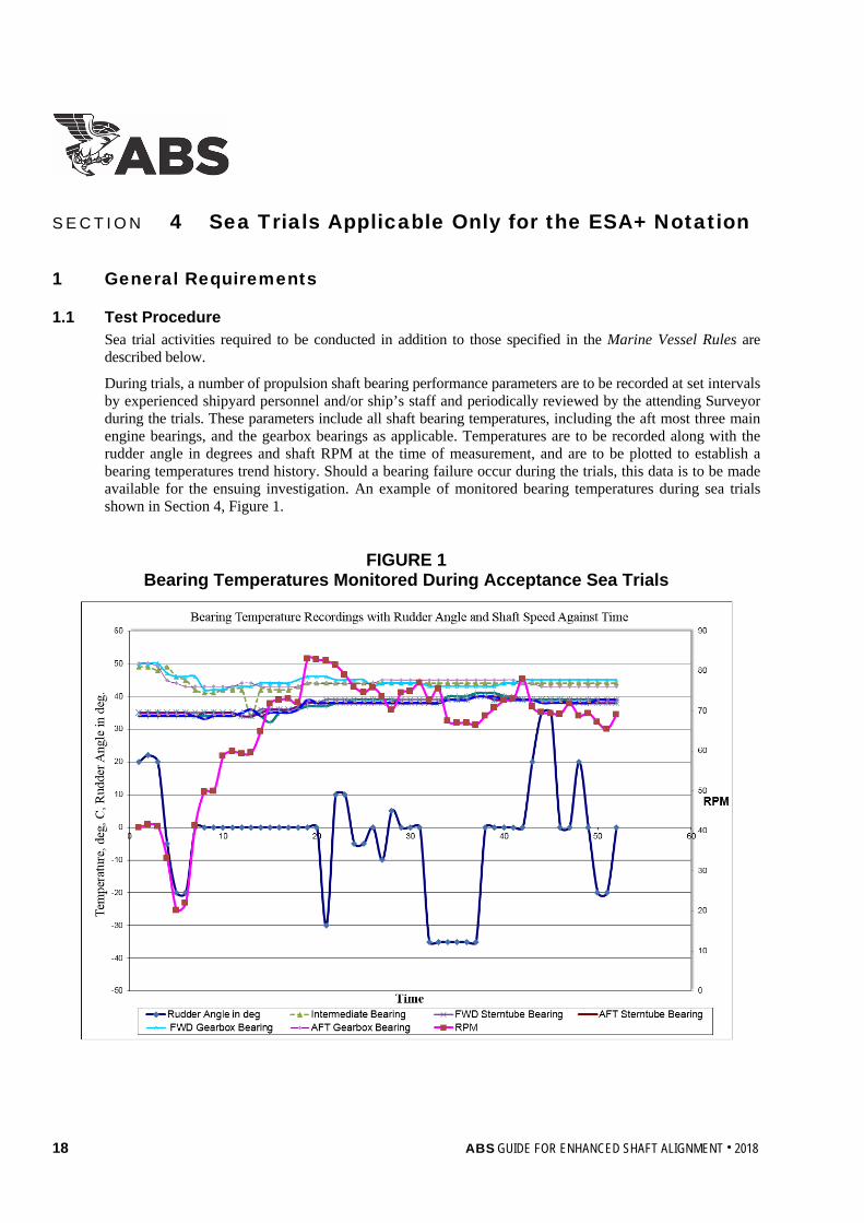
1.1 Test Procedure Sea trial activities required to be conducted in addition to those specified in the Marine Vessel Rules are described below.
During trials, a number of propulsion shaft bearing performance parameters are to be recorded at set intervals by experienced shipyard personnel and/or ship’s staff and periodically reviewed by the attending Surveyor during the trials. These parameters include all shaft bearing temperatures, including the aft most three main engine bearings, and the gearbox bearings as applicable. Temperatures are to be recorded along with the rudder angle in degrees and shaft RPM at the time of measurement, and are to be plotted to establish a bearing temperatures trend history. Should a bearing failure occur during the trials, this data is to be made available for the ensuing investigation. An example of monitored bearing temperatures during sea trials shown in Section 4, Figure 1.
FIGURE 1 Bearing Temperatures Monitored During Acceptance Sea Trials
18 ABS GUIDE FOR ENHANCED SHAFT ALIGNMENT . 2018

Section 4 Sea Trials Applicable Only for the ESA+ Notation
1.3 Bearing Run-in Process A bearing run-in procedure is to be agreed upon between the surveyor and the yard.
The run-in procedure is be conducted as early as possible, before starting full operational sea trials. The procedure progressively exposes the stern bearing to an increased load and assists with bedding in the tail shaft with the stern tube bearing in a controlled manner to create proper contact with the bearing bottom. It prepares the stern tube bearing to endure varying service loads without sustaining damage.
Before commencing the run-in procedure, the vessel is to be brought to deeper waters in open sea, anchored and ballasted to the approved sea trial draft. If the vessel proceeds from the shipyard for sea trials in a light ballast condition with a partially immersed propeller, then low engine RPM and minimum rudder angle movements are recommended.
During the bearing run-in, the aft stern tube bearing temperature is to be closely monitored. If bearing temperature rises at a rate faster than a previously agreed rate, such as 5°C/min, or exceeds the expected temperature threshold, then the rudder angle is to be immediately set to zero and the engine speed reduced to minimum or shut down until the bearing temperature drops to an acceptable level and stabilizes. If limits/criteria/alarms are exceeded, the bearing run-in procedure is to be repeated. If limits/criteria/alarms are exceeded during a repeat run-in procedure, the procedure is to be considered as failed and further investigations are deemed necessary.
Once a bearing run-in procedure is completed to the satisfaction of the attending ABS surveyor, the sea trial program may commence.
1.5 Sea Trials for Shaft Alignment The navigation sea trial is to be carried out with the stern tube lubricant specified in the shaft alignment calculation report. The aft stern tube bearing temperature is to be recorded during the navigation tests included in the sea trial program. The vessel is to stabilize at a full ahead setting, with a zero rudder angle (straight ahead) and at required ballast condition, before carrying out the below tests:
i) Perform one 360-degree port turn with full rudder angle and a full ahead setting. At the completion of the turn, return the rudder angle to zero.
ii) Maintain a zero rudder angle for five (5) minutes at a full ahead setting.
iii) Perform one 360-degree starboard turn with full rudder angle and a full ahead setting. At the completion of the turn, return the rudder angle to zero.
iv) Maintain a zero rudder angle for five (5) minutes at a full ahead setting.
Provided the recorded stern bearing temperature does not exceed a previously agreed rate, such as 5°C/min, or triggers a temperature alarm, the sea trial bearing performance for shaft alignment is regarded as satisfactory.
If acceptable limits, design criteria, and alarm settings are exceeded it may be required to repeat the whole testing procedure (i), ii), iii), iv), as above). In this case, the test will be considered as passed if satisfactory results are demonstrated twice. As a minimum, the test record is to include the maximum rate of temperature rise, the maximum bearing temperature, as well as the alarm set points. Test results are to be included in the sea trial report and sent to the ABS, to be retained for information purposes.
Jack-up tests are to be carried out as required, as per the requirements listed in 4-3-2/11.1.2iii) of the Marine Vessel Rules and are to be submitted to ABS for review.
1.7 Jack-up Tests During Sea Trials In addition to jack-up measurements conducted during drydock and in the lightship condition, ABS Rules require confirmatory bearing reaction measurements for the hot static condition, as specified in 4-3-2/11.1.2(e) of the Marine Vessel Rules.
The results of jack-up tests are to be submitted to ABS for review.
ABS GUIDE FOR ENHANCED SHAFT ALIGNMENT . 2018 19

S e c t i o n 5 : M a i n t e n a n c e o f E S A a n d E S A + N o t a t i o n s
S E C T I O N 5 Maintenance of ESA and ESA+ Notations
1 Modifications A modification, change or incident that may influence the parameters or values of the requested results listed in Sections 2 or 3 of this Guide may be implemented or occur onboard a ship granted the ESA or ESA+ Notation. In these cases, the Notation may be withdrawn until a detailed description of the performed actions, supported by an updated calculation report indicating compliance with the applicable requirements is submitted to ABS for review.
In this respect, ABS is to be notified immediately of vessel incidents that may affect shaft alignment, such as a grounding, or of modifications to any of the powertrain components either at the design stage at the time of assigning the Notation or during of the operational life of the vessel.
20 ABS GUIDE FOR ENHANCED SHAFT ALIGNMENT . 2018

S e c t i o n 6 : S u r v e y s A p p l i c a b l e O n l y f o r t h e E S A + N o t a t i o n
S E C T I O N 6 Surveys Applicable Only for the ESA+ Notation
1 Initial Survey i) All systems required by the ESA+ Notation are to be examined in accordance with the approved
plans to verify compliance.
ii) The ESA+ Notation can be granted upon successful sea trial results.
3 Surveys after Construction In order to maintain the ESA+ Notation, the survey requirements contained in the ABS Rules for Survey After Construction (Part 7) are to be complied with.
ABS GUIDE FOR ENHANCED SHAFT ALIGNMENT . 2018 21

A p p e n d i x 1 : D e f i n i t i o n s o f S h a f t A l i g n m e n t O p t i m i z a t i o n
A P P E N D I X 1 Definitions of Shaft Alignment Optimization
The ABS Shaft Alignment Optimization software program involves an iteration process that is based on the genetic algorithm (GA) method, wherein a solution is sought by a parallel search throughout the solution space bounded by two “extreme” deflection curves, namely in this application, the ballast and the fully-laden condition. Within the defined solution space, the desired number of acceptable solutions that comply with the basic alignment requirements is extracted. It is then up to the designer to select the solution that delivers the most robust, practical and acceptable design.
In accordance with the ABS definition of shaft alignment optimization, the following definitions are observed:
i) Objective Function (OF). To minimize the difference of magnitude of the reaction forces among the bearing reaction forces rendering them as uniform as possible for all the bearings within the whole powertrain.
ii) Design Variable (DV). All selected bearing offsets.
iii) State Variable (SV). Two limit lines of bearing offset sets, or surfaces, describing the ballast and fully laden condition and based on the hull deflection data.
The above definitions are generic in design optimization problems and can be found in various literature survey related articles, see Appendix 1, Figures 1 and 2.
1 Shaft Alignment Optimization Alternative Definitions Alternative definitions and analyses of shaft alignment optimization could be acceptable for the purposes of granting the ESA or ESA+ Notation; however, these are to be to the satisfaction of ABS and may be considered on a case-by-case basis. The report required in 1/5.1 is to detail the calculation process and the assumptions made. The submitted calculations are to include a clear definition of the shaft alignment optimization method including the relevant definitions of the design optimization such as the objective function, the state variables and the design variables (OF, SV, DV).
FIGURE 1 2D Design Optimization Mathematical Concept
22 ABS GUIDE FOR ENHANCED SHAFT ALIGNMENT . 2018

Appendix 1 Definitions of Shaft Alignment Optimization
FIGURE 2 3D and higher Design Optimization Mathematical Concept
ABS GUIDE FOR ENHANCED SHAFT ALIGNMENT . 2018 23

A p p e n d i x 2 : R e f e r e n c e s
A P P E N D I X 2 References
1. ABS, Guidance Notes on Propulsion Shafting Alignment, 2018.
2. ABS Shaft Alignment and Alignment Optimization Software, Version 3.0, Users Manual, ABS, 2016.
24 ABS GUIDE FOR ENHANCED SHAFT ALIGNMENT . 2018