enhanced qos support in certified wireless · pdf file4.2 simulation process ... 41 diagram...
TRANSCRIPT

ENHANCED QOS SUPPORT INCERTIFIED WIRELESS USB
By
Issam Al-Dalati
School of Information Technology and Engineering
Submitted in partial fulfillment of
the requirements for the degree of
Master of Applied Science1
Faculty of Graduate and Postdoctoral Studies
The University of Ottawa
Ottawa, Ontario
May 2011
c© Issam Al-Dalati ,Ottawa,Canada, 2011
1The M.A.Sc. is part of The Ottawa-Carleton Institute for Electrical and Computer Engineering

Abstract
The growth of high speed internet wired access in buildings, home and offices are driv-
ing the need for a technology like UWB to provision bandwidth sharing over wireless
devices. Certified Wireless Universal Serial Bus (WUSB) is one of different varieties
of Wimedia standards for distributed Medium Access Control (MAC) protocol for
UWB communications in the Wireless Personal Area Network (WPAN). To the best
of our knowledge, no technical contributions exist in the open literature at present
simulating WUSB and its performance.
Our study investigates the performance of the WUSB standards and compares
it to the Wimedia Standard. The study showed that WUSB can achieve better
throughput when bursting is enabled at the maximum burst size and it provides
more accurate timing control of device activity than using the standard facilities of
the WiMedia MAC. Our study also addresses protocol extensions and improvement
to the original WUSB standard to support better Quality of Service (QoS). First
improvement enables a different reservation mechanism along with contention based
access to support higher priority security and medical system monitoring applications.
Second improvement enables the host device to use an adaptive packet loss technique
to change the packet size dynamically during the data transmission to achieve packet
loss less than 10%. Third improvement enables redundancy in the cluster by adding
a backup host to prevent mobility failures and changes. This backup host is chosen
by a predefined cost weighting function.
ii

Acknowledgements
I would like to express my deepest gratitude to both my thesis supervisor Professor
Dr. Dimitrios Makrakis and my thesis co-supervisor Professor Dr. Ashraf Matrawy
for their continuous support, supervision, patience and encouragement during this
project. I would not have completed this thesis project successfully without their
assistance.
I would like to thank my wife for her patience and support. I would also thank
my parents for their prayers and their help to babysit my son Tarek in the last few
months.
iii

Dedication
Dedicated to my father and mother.
iv

Contents
Abstract ii
Acknowledgements iii
Dedication iv
Acronyms 1
1 Introduction 5
1.1 Background Overview . . . . . . . . . . . . . . . . . . . . . . . . . . 5
1.2 Standardization . . . . . . . . . . . . . . . . . . . . . . . . . . . . . . 8
1.2.1 Bluetooth 3.0 . . . . . . . . . . . . . . . . . . . . . . . . . . . 11
1.2.2 Wimedia Link Layer Protocol (WLP) . . . . . . . . . . . . . . 11
1.2.3 Wireless 1394 (Wireless Firewire) . . . . . . . . . . . . . . . . 11
1.2.4 Certified Wireless USB (WUSB) . . . . . . . . . . . . . . . . . 12
1.3 UWB Applications . . . . . . . . . . . . . . . . . . . . . . . . . . . . 12
1.4 Motivation and Thesis Objectives . . . . . . . . . . . . . . . . . . . . 14
1.5 Thesis Contributions . . . . . . . . . . . . . . . . . . . . . . . . . . . 14
1.6 Thesis Organizations . . . . . . . . . . . . . . . . . . . . . . . . . . . 15
2 Certified WUSB 16
2.1 WUSB Cluster Architecture . . . . . . . . . . . . . . . . . . . . . . . 16
2.1.1 WUSB Host . . . . . . . . . . . . . . . . . . . . . . . . . . . . 17
2.1.2 WUSB Device . . . . . . . . . . . . . . . . . . . . . . . . . . . 17
v

2.1.3 WUSB DRD . . . . . . . . . . . . . . . . . . . . . . . . . . . 18
2.2 Physical Layer . . . . . . . . . . . . . . . . . . . . . . . . . . . . . . . 18
2.3 MAC Layer Channel . . . . . . . . . . . . . . . . . . . . . . . . . . . 22
2.3.1 Wimedia MAC Layer Channel . . . . . . . . . . . . . . . . . . 23
2.3.1.1 DRP . . . . . . . . . . . . . . . . . . . . . . . . . . . 24
2.3.1.2 PCA . . . . . . . . . . . . . . . . . . . . . . . . . . . 29
2.3.2 WUSB MAC Layer Channel . . . . . . . . . . . . . . . . . . . 30
2.4 WUSB MAC Layer Main Features . . . . . . . . . . . . . . . . . . . . 32
2.4.1 Data Bursting . . . . . . . . . . . . . . . . . . . . . . . . . . . 32
2.4.2 Synchronization . . . . . . . . . . . . . . . . . . . . . . . . . . 34
2.4.3 Resiliency Against Hidden Terminal Problem . . . . . . . . . 34
2.5 WUSB Connection Setup . . . . . . . . . . . . . . . . . . . . . . . . . 35
2.6 WUSB Data Transactions . . . . . . . . . . . . . . . . . . . . . . . . 36
2.6.1 Bulk Data Transfers . . . . . . . . . . . . . . . . . . . . . . . 38
2.6.2 Isochronous Data Transfers . . . . . . . . . . . . . . . . . . . 38
2.6.3 Interrupt Data Transfers . . . . . . . . . . . . . . . . . . . . . 38
2.6.4 Control Data Transfers . . . . . . . . . . . . . . . . . . . . . . 39
2.6.5 Asynchronous Device Notification Transfers . . . . . . . . . . 39
2.7 WUSB Bandwidth Reservation Policy . . . . . . . . . . . . . . . . . . 40
2.8 Packet Formats . . . . . . . . . . . . . . . . . . . . . . . . . . . . . . 41
2.8.1 MAC General Header . . . . . . . . . . . . . . . . . . . . . . . 41
2.8.2 Beacon Packet . . . . . . . . . . . . . . . . . . . . . . . . . . . 43
2.8.3 BPOIE Format . . . . . . . . . . . . . . . . . . . . . . . . . . 44
2.8.4 DRP IE Format . . . . . . . . . . . . . . . . . . . . . . . . . . 46
2.8.5 WUSB Data Packet Header . . . . . . . . . . . . . . . . . . . 47
2.8.6 WUSB Data Packet Header for Isochronous Packets . . . . . . 49
2.8.7 MMC Packet . . . . . . . . . . . . . . . . . . . . . . . . . . . 50
2.9 Power Management . . . . . . . . . . . . . . . . . . . . . . . . . . . . 52
2.10 Security . . . . . . . . . . . . . . . . . . . . . . . . . . . . . . . . . . 53
2.10.1 Association Method . . . . . . . . . . . . . . . . . . . . . . . . 54
2.10.2 Authentication Method . . . . . . . . . . . . . . . . . . . . . . 55
vi

2.10.3 Encryption Method . . . . . . . . . . . . . . . . . . . . . . . . 55
3 Related Work 56
3.1 Wimedia Related Work . . . . . . . . . . . . . . . . . . . . . . . . . . 56
3.1.1 DRP Reservation Based Only . . . . . . . . . . . . . . . . . . 56
3.1.2 PCA Contention Based Only . . . . . . . . . . . . . . . . . . 59
3.1.3 PCA and DRP Combination Study . . . . . . . . . . . . . . . 60
3.1.4 Certified WUSB Related Work . . . . . . . . . . . . . . . . . 61
4 Performance Analysis 63
4.1 Simulation Software . . . . . . . . . . . . . . . . . . . . . . . . . . . . 63
4.2 Simulation Process . . . . . . . . . . . . . . . . . . . . . . . . . . . . 66
4.3 Simulator Settings . . . . . . . . . . . . . . . . . . . . . . . . . . . . 67
4.4 Simulation Assumptions . . . . . . . . . . . . . . . . . . . . . . . . . 69
4.5 Optimal Performance Analysis . . . . . . . . . . . . . . . . . . . . . . 69
4.5.1 Wimedia Theoretical Analysis . . . . . . . . . . . . . . . . . . 70
4.5.2 WUSB Theoretical Analysis . . . . . . . . . . . . . . . . . . . 75
4.5.3 Simulation Analysis under Perfect Conditions . . . . . . . . . 81
4.5.4 Simulation Analysis under Connection Failures . . . . . . . . . 83
5 Protocol Improvements to Certified WUSB 84
5.1 Enabling Priority Option for Delay Sensitive Applications . . . . . . . 84
5.1.1 Background and Motivation . . . . . . . . . . . . . . . . . . . 84
5.1.2 Proposed Model . . . . . . . . . . . . . . . . . . . . . . . . . . 86
5.1.3 Simulation Results . . . . . . . . . . . . . . . . . . . . . . . . 87
5.2 Adaptive Packet Size Host Extension to Reduce Packet Loss . . . . . 90
5.2.1 Background and Motivation . . . . . . . . . . . . . . . . . . . 90
5.2.2 Proposed Model . . . . . . . . . . . . . . . . . . . . . . . . . . 92
5.2.3 Simulation Results . . . . . . . . . . . . . . . . . . . . . . . . 93
5.3 Dynamic Host Backup Selction (DHBS) Protocol in Certified WUSB 95
5.3.1 Background and Motivation . . . . . . . . . . . . . . . . . . . 95
5.3.2 Proposed Model . . . . . . . . . . . . . . . . . . . . . . . . . . 96
vii

5.3.3 Simulation Results . . . . . . . . . . . . . . . . . . . . . . . . 97
6 Conclusion and Recommendation for Future Work 100
Bibliography 102
viii
List of Tables
1 Physical layer Modulation and Data rate Parameters . . . . . . . . . 20
2 Parameters of WUSB and Wimedia Wireless OFDM Symbol. . . . . . 22
3 Zone priorities of Rule 3. . . . . . . . . . . . . . . . . . . . . . . . . . 29
4 Priority Parameters in Wimedia MAC . . . . . . . . . . . . . . . . . 30
5 WUSB Bandwidth Reservation Policy Parameters. . . . . . . . . . . . 41
6 Packet Type Field Encoding. . . . . . . . . . . . . . . . . . . . . . . . 41
7 ACK Policy Field Encoding. . . . . . . . . . . . . . . . . . . . . . . . 42
8 WUSB PID Types. . . . . . . . . . . . . . . . . . . . . . . . . . . . . 48
9 Common Standard Parameters for WUSB and Wimedia MAC. . . . . 70
10 NS-2 Simulation Parameters . . . . . . . . . . . . . . . . . . . . . . . 88
11 Parameters in Backup Weighting Function of the DHBS Protocol . . 97
ix
List of Figures
1 Relative Power of UWB Signal . . . . . . . . . . . . . . . . . . . . . . 7
2 FCC Spectral Mask for UWB Indoor Communication Systems [1] . . 8
3 UWB Five Frequency Bands of Multiband OFDM . . . . . . . . . . . 9
4 Wimedia Physical, MAC and PAL Layers . . . . . . . . . . . . . . . . 10
5 Examples of Smart Home Wireless Network Applications based on UWB 13
6 WUSB cluster topologies and node types. . . . . . . . . . . . . . . . . 16
7 General ECMA-368 Packet Format. . . . . . . . . . . . . . . . . . . . 21
8 Super Frame General Format. . . . . . . . . . . . . . . . . . . . . . . 24
9 General Model of Wimedia MAC Layer Channel. . . . . . . . . . . . 25
10 MAS Allocation Rules. . . . . . . . . . . . . . . . . . . . . . . . . . . 28
11 General Model of WUSB MAC Layer Channel. . . . . . . . . . . . . 31
12 Data Bursting as Specified in WUSB Standard [9]. . . . . . . . . . . 33
13 UWSB Connection Setup State Diagram. . . . . . . . . . . . . . . . . 35
14 UWSB Data Transaction. . . . . . . . . . . . . . . . . . . . . . . . . 37
15 MAC Header General Format. . . . . . . . . . . . . . . . . . . . . . . 43
16 Beacon Packet General Format. . . . . . . . . . . . . . . . . . . . . . 44
17 BPOIE Payload Format. . . . . . . . . . . . . . . . . . . . . . . . . . 45
18 DRP IE Payload Format. . . . . . . . . . . . . . . . . . . . . . . . . . 47
19 WUSB Data Packet Header Format. . . . . . . . . . . . . . . . . . . 48
20 WUSB Isochronous Data Packet Header Format. . . . . . . . . . . . 49
21 MMC Packet Format. . . . . . . . . . . . . . . . . . . . . . . . . . . . 51
22 Security fields addition in WUSB MAC Packet. . . . . . . . . . . . . 54
23 Connectivity Within a local network from [27] . . . . . . . . . . . . . 64
x

24 Simulation Proccess Steps . . . . . . . . . . . . . . . . . . . . . . . . 66
25 Settings Script in .tcl . . . . . . . . . . . . . . . . . . . . . . . . . . . 67
26 (a)Wimedia Immediate ACK Outgoing Data Transfer. (b)Wimedia
Immediate ACK Incoming Data Transfer. . . . . . . . . . . . . . . . . 72
27 (a)Wimedia Burst ACK Outgoing Data Transfer. (b)Wimedia Burst
ACK Incoming Data Transfer. . . . . . . . . . . . . . . . . . . . . . . 74
28 Theortical Wimedia Packet Delivery Ratio with All Supported Bit Rates 75
29 Theortical Wimedia Packet Delivery Ratio with All Supported Packet
Sizes at 480Mbps . . . . . . . . . . . . . . . . . . . . . . . . . . . . . 75
30 (a)WUSB Immediate ACK Outgoing Data Transfer. (b)WUSB Imme-
diate ACK Incoming Data Transfer. . . . . . . . . . . . . . . . . . . . 76
31 (a)WUSB Burst ACK Outgoing Data Transfer. (b)WUSB Burst ACK
Incoming Data Transfer. . . . . . . . . . . . . . . . . . . . . . . . . . 78
32 Theortical WUSB Packet Delivery Ratio with All Supported Bit Rates 80
33 Theortical WUSB Packet Delivery Ratio with All Supported Packet
Sizes at 480Mbps . . . . . . . . . . . . . . . . . . . . . . . . . . . . . 80
34 Simulation Comparing Wimedia and WUSB Packet Delivery Ratio
with All Supported Bit Rates . . . . . . . . . . . . . . . . . . . . . . 81
35 Simulation Comparion Wimedia and WUSB Packet Delivery Ratio
with All Supported Packet Sizes at 480Mbps . . . . . . . . . . . . . . 82
36 Simulation Comparing Wimedia and WUSB Packet Delivery Ratio
with All Supported Bit Rates under 10% Packet Loss . . . . . . . . . 83
37 Security and Medical Monitoring Systems in a Wireless Home Network 85
38 Throughput Simulation based on WUSB Private DRP MAC . . . . . 89
39 Throughput Simulation Comparison based on PCA and Soft DRP MAC 90
40 Total Average Packet Loss Simulation Comparison with All Supported
Packet Sizes . . . . . . . . . . . . . . . . . . . . . . . . . . . . . . . . 92
41 Diagram of the Proposed Adaptive Packet Change Mechanism at Host
Side. . . . . . . . . . . . . . . . . . . . . . . . . . . . . . . . . . . . . 94
42 Average Packet Loss Rate Comparison with Adaptive Host Packet Size
Method . . . . . . . . . . . . . . . . . . . . . . . . . . . . . . . . . . 95
xi

43 Mobility Scenario used to verify DHBS protocol . . . . . . . . . . . . 98
44 Packet Delivery Ratio Results with Mobility Scenario for DHBS Veri-
fication . . . . . . . . . . . . . . . . . . . . . . . . . . . . . . . . . . . 99
45 Average Delay Packet Results with Mobility Scenario for DHBS Veri-
fication . . . . . . . . . . . . . . . . . . . . . . . . . . . . . . . . . . 99
xii

Acronyms
AIFS Arbitration Inter-Frame Space
ARP Address Resolution Protocol
BPOIE Beacon Period Occupancy Information Element
CA Collision Avoidance
CBC Cipher Block Chaining Message Authentication Code
CSMA Carrier Sense Multiple Access
CTS Clear to Send
DCM Dual Carrier Modulation
EDCA Enhanced Distributed Channel Access
DHBS Dynamic Host Backup Selection
DLNA Digital Living Network Alliance
DNTS Device Notification Time Slot
DR Device Receive
DRD Dual Role Device
DRP Distributed Reservation Protocol
DS-CDMA Direct Sequence Code Division Multiple Access
1

2
DSP Digital Signal Processor
DT Device Transmit
DWA Device Wire Adapter
ECMA European Computer Manufacturers Association
ETSI European Telecommunications Standards Institute
FCC Federal Communication Comission
FEC Forward Error Correction
GPR Ground Penetrating Radar
GPS Global Positioning System
HDTV High Definition TV
HWA Host Wire Adapter
IE Information Element
IEEE Institute of Electrical and Electronics Engineers
ISIMA Improved Service Interval-based MAS Allocation
ISO International Organization for Standardization
LLC Logical Link Control
MAC Media Access Control
MAP Markovian Arrival Process
MAS Medium Access Slot
MBOA Multiband OFDM Alliance
MGM Matrix Geometric Method
3
MIC Message Integrity Code
MIFS Minimum Inter-Frame Spacing
MMC Micro-Scheduled Management Commands
MMPP Markov Modulated Poisson Process
NAK Negative Acknowledgement
NAV Network Allocation Vector
NFC Near Field Communication
NLMS Normalized Least Mean Square
NOAH No Ad Hoc Routing
NS-2 Network Simulator 2
OFDM Orthogonal Frequency Division Multiplexing
OSI Open System Interconnection
PAL Protocol Adaptation Layer
PCA Priority Contention Access
PER Packet Error Rate
PSD Power Spectral Density
QBD Quasi Birth and Death
QoS Quality of Service
QPSK Quadrature Phase Shift Keying
RF Radio Frequency
RTS Request to Send

4
SDK Software Development Kit
SFN Secure Frame Number
SIFS Short Inter-Frame Spacing
SIG Special Interest Group
TDMA Time Division Multiple Access
TG Transaction Group
TKID Temporal Key Identifier
TOA Time of Arrival
UWB Ultra Wide Band
WCTA WUSB Channel Time Allocation
WLPl Wimedia Link Protocol
WPAN Wireless Personal Area Network
WSS Wimedia Service Set
WUSB Wireless Universal Serial Bus
WXP Wimedia Extended Platform

Chapter 1
Introduction
1.1 Background Overview
UWB is a Radio Frequency (RF) technology that transmits binary data, using low
energy and very short duration impulses or bursts (in the order of picoseconds) over
a wide spectrum of frequencies. On February 14 2002, Federal Communications
Commission (FCC) published a regulatory report allowing UWB signal transmissions
with radiated Power Spectral Density (PSD) below 42dBm/MHz in the 3.1GHz-10.6
GHz frequency range. The FCC defines a UWB radio signal as having the fractional
bandwidth of at least 0.20 or has a spectral bandwidth of at least 500 MHz [1]. In
other words, UWB signal should be meet the criteria in either equation (1) or (2).
(fH − fLfC
) > 0.20 (1)
Or
(fH − fL) ≥ 500MHz (2)
Where fH and fL are the upper and lower frequency of the 10 dB emission point. fC
is the centre frequency of the emission and can be calculated in equation (3)
fC =fH + fL
2(3)
5

CHAPTER 1. INTRODUCTION 6
The fractional bandwidth of an UWB emission is defined as ratio of the signals band-
width to the signals center frequency as in (4)
FractionalBandwidth(%) =2 ∗ (fH − fL)
(fH + fL)∗ 100 (4)
There are several advantages and features UWB technology offers:
According to the Shannon theorem, the channel capacity grows linearly with band-
width and decreases logarithmically as the signal-to-noise ratio (SNR) decreases. This
equation below suggests that the radio capacity can be increased more rapidly by in-
creasing the occupied bandwidth than the (Signal to Noise) SNR ratio.
C = B ∗ log2(1 +S
N) (5)
C is the maximum channel capacity in (bits/second). B is the channel bandwidth in
Hz. S is the signal power and N is the noise power in Watts. Therefore, UWB can
achieve the highest data rate while maintaining a very low signal power density [2].
Another main advantage to UWB is it’s excellent immunity to multi path fading.
Multipath around obstacles can cause a significant degradation in the propagation
of the signals and decrease in the communication performance. This degradation
would have a serious impact on tracking application that requires accuracy in re-
solving targets and positions. UWB have bandwidths exceeding 0.5 GHz which are
capable of resolving multipath components with less than nanosecond delays. Those
UWB multipath delays can be resolved and added constructively to provide gain over
a single direct path in the multipath environment. This gain helps in achieving a
better accuracy within a few centimetres [2]. The advantage of immunity to multi
path fading also allows UWB to give high accurate distance estimation for location
ranging between two nodes and estimating the location of an object. One of the most
common ranging techniques is called Time of Arrival (TOA) where distance is cal-
culated by measuring the delay between two nodes with a two way packet exchange
method. This method doesnt require synchronization between the sender and the
receiver node [3].

CHAPTER 1. INTRODUCTION 7
UWB signal also incurs low loss when penetrating through material due to the
various energy levels at different frequencies. The reason is that UWB pulse has a
wide frequency spectrum and each pulse has a duration that is very small and short
which leads to low energy consumption [4].
UWB is considered to have low lower spectral density. The reason FCC regula-
tions limit UWB devices to low average power in order to minimize interference with
narrowband systems. UWB is unique in that its radiated power is inherently ultra
low as mandated by the FCC maximum of 560 µW, which is at least an order of
magnitude less than the radiated power of narrowband systems see figure 1.
Frequency (MHz)
SignalEnergy(dbm/MHz)
Narrow Band
Spread Spectrum
UWB
-41.3FCC Threshold
Figure 1: Relative Power of UWB Signal
For example, in indoor systems the average output power spectral density is lim-
ited to -41.3 dBm per MHz as in figure 2, which complies with the long standing Part
15 general emission limits to successfully control radio interference to other narrow-
band indoor wireless technologies [1].
The UWB technology can be also implemented on small size, low cost and low
power devices which involve less complex Digital Signal Processors (DSPs). UWB

CHAPTER 1. INTRODUCTION 8
wireless signals dont need transmitting power amplifiers which is a great advantage
over narrowband systems that require amplifiers with significant power to support
high order modulation waveforms for high data rates. Therefore, UWB can achieve
higher data rates with much less complexity and much higher power efficiency than
any of the narrower band technologies [2].
Figure 2: FCC Spectral Mask for UWB Indoor Communication Systems [1]
Last but not least, UWB signal is appropriate for security applications because it
has low energy and it’s spectral density is below the noise floor of common receivers.
It also occupies a wide bandwidth which is harder to detect than conventional radio.
These main characteristics result in UWB secure transmissions with low probability
of detection and low probability of interception by un-authorized users. In Addition,
FCC defined AES-128 Symmetric security for payload protection and integrity [2].
1.2 Standardization
During the IEEE 802.15 High Rate Alternative PHY Task Group (TG3a) discussions
for WPAN, two major contenders were trying to convince that IEEE work group to
CHAPTER 1. INTRODUCTION 9
accept one of the techniques suggested for that standard. One technique was im-
pulse based called Direct Sequence Code Division Multiple Access (DS-CDMA) led
by Xtreme Spectrum, Motorola and Parthus-Carva. It consists of stream of data
divided into pulses where each is allocated to a frequency channel across the spec-
trum. That group went on to create the UWB Forum. The other technique was
multi-carrier based which uses Orthogonal Frequency Division Multiplexing (OFDM)
theory to transmit information on each of the spectrum sub-bands. It was led mainly
by Intel and Texas Instruments. That IEEE TG3a workgroup decided to disband the
group in January 2006 without reaching to an agreement for the standard. In June
2003, Intel created a group called Multiband OFDM alliance (MBOA) to produce a
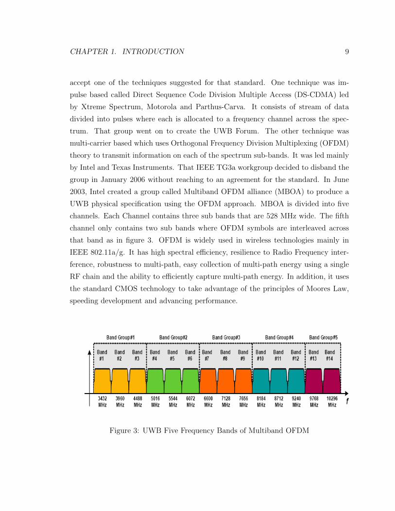
UWB physical specification using the OFDM approach. MBOA is divided into five
channels. Each Channel contains three sub bands that are 528 MHz wide. The fifth
channel only contains two sub bands where OFDM symbols are interleaved across
that band as in figure 3. OFDM is widely used in wireless technologies mainly in
IEEE 802.11a/g. It has high spectral efficiency, resilience to Radio Frequency inter-
ference, robustness to multi-path, easy collection of multi-path energy using a single
RF chain and the ability to efficiently capture multi-path energy. In addition, it uses
the standard CMOS technology to take advantage of the principles of Moores Law,
speeding development and advancing performance.
Figure 3: UWB Five Frequency Bands of Multiband OFDM

CHAPTER 1. INTRODUCTION 10
MBOA group was then merged into a Wimedia Alliance which was initially cre-
ated as a nonprofit organization to promote applications based on MBOA platform
[5]. Wimedia then submitted the technical specification to an international standard
called the European Computer Manufacturers Association (ECMA) in 2005. ECMA
approved two specifications for Wimedia. One is called ECMA-368 based on the PHY
layer and MAC sub-layer specification. The other one is called ECMA-369 and was
around the interface between the physical and MAC layers [6]. The second specifi-
cation is not mandatory for the manufacturers to follow. The ECMA-368 standard
was also published by the International Organization for Standardization (ISO) and
the European Telecommunications Standards Institute (ETSI). The thesis is based
on ECMA-368 solely.
Wimedia is not only designed to specify the physical and MAC layers but also
to facilitate heterogeneous devices from different manufactures to operate within the
same WPAN. Wimedia defines a convergence layer after the MAC layer called Pro-
tocol Adaptation Layer (PAL). This layer supports a number of defined protocol
adaptation layers; see figure 4. The most common protocol adaptation layers are
listed in figure 4 and summarized in the following subsections.
Wimedia PHY Layer
Wimedia MAC Layer
WLPWireless1394
Bluetooth 3.0
WUSB
Figure 4: Wimedia Physical, MAC and PAL Layers

CHAPTER 1. INTRODUCTION 11
1.2.1 Bluetooth 3.0
Bluetooth Special Interest Group (SIG) announced in 2006 that they will upgrade
to Bluetooth 3.0 based on Wimedia UWB technology. However, Bluetooth 3.0 Spec-
ification required that each Bluetooth be backwards compatible with Bluetooth 2.1
which means that Bluetooth 3.0 will have two MAC platforms. One based on the old
Bluetooth MAC and the other based on a different high rate MAC layer. The alter-
nate Phy/MAC layer (AMP) feature of Bluetooth 3.0 is based on 802.11 and designed
to be usable with other radios. Currently the Bluetooth SIG suspended development
of the Wimedia PAL integration and its still in process of evaluating other options.
1.2.2 Wimedia Link Layer Protocol (WLP)
Wimedia specifications define a PAL that adds TCP/IP services to the Wimedia
platform to model a behavior of an IEE 802.11 network. WLP basically ties the
Wimedia MAC and physical layers to the the network layer by acting as the Logical
Link sub Layer (LLC) in the data link layer. WLP uses a concept called Wimedia
Service Set (WSS) which is a group of devices that share a security relationship. WLP
is considered the only standalone PAL that is developed by Wimedia. Wimedia is
currently working on Wimedia Extended Platform (WXP) which targets higher layers
to allow fully interoperable IP-based applications. Wimedia is currently working with
Digital Living Network Alliance (DLNA) to insure interoperability.
1.2.3 Wireless 1394 (Wireless Firewire)
Wireless Firewaire is a wireless version of the high speed Firewire communication
protocol defined in IEEE 1394. In May 2004, the 1394 trade association approved the
development of a PAL to have IEEE 1394 work over UWB with Wimedia integration.
However, it also needs intelligent channel allocation time to transmit multimedia data
by real time [7]. Moreover, Wireless Firewire has a limited applicability in that it can
only be applied to newly developed 1394 devices since it requires that the physical
and link layers be modified from the original 1394 standard [8].

CHAPTER 1. INTRODUCTION 12
1.2.4 Certified Wireless USB (WUSB)
The WUSB Promoter Group was formed at 2004 Intel Developer Forum and is com-
prised of seven industry leaders which are Agere Systems, HP, Intel, Microsoft Cor-
poration, NEC, Philips Semiconductors and Samsung Electronics. WUSB is a short
range wireless communication protocol and is considered the new wireless extension
to USB. WUSB is not considered a PAL by itself. The UWUSB standard described
it as a standalone MAC layer but WUSB uses the majority of the functionality of the
Wimedia MAC layer.
1.3 UWB Applications
Two major things are deriving the market for UWB technology in WPANs. First one
is the need to have less cable indoors and around home or entertainment networks.
Second is the need for reliable easy to use high speed wireless networking devices.
Initially UWB systems were used in military and mainly in radar imaging systems.
It can obtain images of obstructed objects for applications such as wall/through-wall
detection, ground penetrating radar, medical imaging, construction and home repair
imaging, mining, and surveillance systems.
The growth of UWB technology will be mainly in wireless home networks that require
high bit rate short communication devices running without cables. Smart wireless
devices can be any electronic devices such as computers, digital cameras, printers,
scanners, High Definition TV (HDTV) and various game consoles. For example,
home theater environment could be constructed without cables and with minimum
effect on performance. So a blue ray DVD player can broadcasted to the TV without
cables. Also, Users can use their cell phone to send documents to print on the printer
wirelessly (See figure 5 ).
Tha advantage of relying on the high ranging accuracy and target differentiation
capability enabled by UWB can be integrated into cars to provide collision avoidance,

CHAPTER 1. INTRODUCTION 13
Local high throughput delivery
Long range deliverywired or wireless
(backbone)
Applications
Figure 5: Examples of Smart Home Wireless Network Applications based on UWB
detecting the movement and location of objects near a vehicle, improving airbag ac-
tivation and suspension settings. UWB immunity to interference and being below
narrowband noise level will help to not interfere with other technologies like Global
Positioning System (GPS). Positioning devices could be used to assist vehicles to
be guided along a highway by integrating UWB technology along the road. Secu-
rity can use UWB technology in security applications such as Ground Penetrating
Radar (GPR), through-wall surveillance, wireless monitoring of children, people with
medical need and objects.
In this thesis, the focus will be around the use of UWB in wireless home networks
or smart homes.

CHAPTER 1. INTRODUCTION 14
1.4 Motivation and Thesis Objectives
With the diverse traffic types supported in the wireless network with different re-
quirements in terms of service parameters needed for each application to operate,
UWB systems need to be designed to support the transfer of extremely high data
rates over short distance with QoS support. MAC layer design is one of the impor-
tant functions of that system since it handles channel access while maintaining QoS
and Security. MAC design needs to tackle network issues like high packet loss rate,
large packet delay, packet delay variations, mobility of users and security. WUSB
appears to be superior to the other solutions because the integration with Wimedia
is easier to implement than the other technologies. In addition, the WUSB standard
has optional parameters that can be used to help meet QoS of certain applications in
home wireless networks. Based on that fact and to the best of our knowledge there
is no work in the open literature analyzing in detail the performance of WUSB. Our
objective in this thesis is to analyze the performance of this promising technology,
as well provide modifications that improve its performance and increase its capacity
further to enhance the QoS support.
1.5 Thesis Contributions
In this thesis we propose three improvements to the current WUSB MAC layer to
help in achieving better QoS for wireless home network. First proposal is to modify
the WUSB standard to enable prioritization in both Distributed Reservations Pro-
tocol (DRP) and Priority Contention Access (PCA) types. We are going to proof in
simulation implemented in ns-2 that soft DRP and PCA can be enabled in WUSB to
support higher priority security or medical monitoring systems with guaranteed QoS.
The second proposed method is to add to the host node a mechanism to dynamically
change the packet size used in any data transfer to minimize the packet loss rate
occuring in the network. This packet loss reduction and adjustment can help support
voice and video multimedia applications to meet QoS standards. The third proposed
method is to enable a redundant host in the cluster to backup the original host in case
CHAPTER 1. INTRODUCTION 15
of topology changes and mobility. We also came up with directions and suggestions
for future research.
1.6 Thesis Organizations
The remainder of the thesis is organized as follows. In chapter 2, we will give an
overview of WUSB MAC and the common functionality with Wimedia. In chapter
3, we will review the literature study around the performance of Wimedia in general
and WUSB in specific. In chapter 4, We will also describe the simulator used in our
project and verify the performance of both implementations of Wimedia and WUSB
MAC layers. We will provide in chapter 5 the details of the protocol extensions
we proposed for WUSB and simulations of the proposed models. Finally, chapter 6
concludes the thesis and discusses some future work.
Chapter 2
Certified WUSB
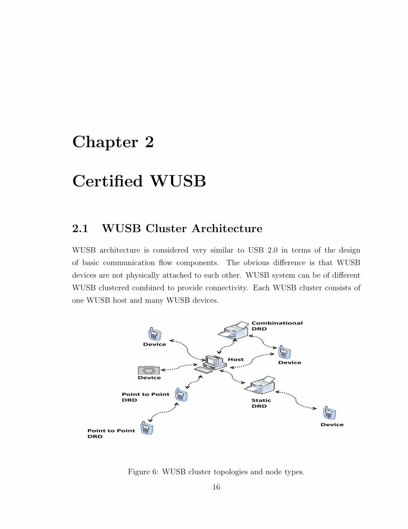
2.1 WUSB Cluster Architecture
WUSB architecture is considered very similar to USB 2.0 in terms of the design
of basic communication flow components. The obvious difference is that WUSB
devices are not physically attached to each other. WUSB system can be of different
WUSB clustered combined to provide connectivity. Each WUSB cluster consists of
one WUSB host and many WUSB devices.
Host
Device
Device
Device
StaticDRD
Device
CombinationalDRD
Point to PointDRD
Point to PointDRD
Figure 6: WUSB cluster topologies and node types.
16

CHAPTER 2. CERTIFIED WUSB 17
The cluster is a star topology where there is a point to point communication
between each of the device directly back to the host as showed in figure 6. A cluster
consists of two main nodes. One is called a host and the other is called a device.
One WUSB host can logically connect to a maximum of 127 WUSB devices to create
a WUSB cluster. Moreover, there is a special node called Dual Role Device (DRD)
which acts as both a host and a device in a cluster.
2.1.1 WUSB Host
WUSB is the node that initiates beaconing in the wireless cluster after checking if
there is no other existing beacon found. WUSB host should have the full functionality
of the Wimedia MAC layer implemented in order to organize access to the wireless
medium. WUSB hosts are required to support all data rates for both transmission
and reception. A wired USB host can be enabled to become a WUSB host by adding
an adapter. The adapter is called Host Wire Adapter (HWA) attached to the host
device such as a PC to allow the PC to connect through the wireless medium. As
shown in figure 6, a PC can become a WUSB host if a HWA is attached to one of its
existing USB ports. This way it can create a cluster around it for a maximum of 10
meter range.
2.1.2 WUSB Device
A WUSB device is a wireless device that is connected to a cluster with an already
established channel beaconing by a host. The device entity doesnt need to initiate
new beacons. It can just join an existing channel and stay as a WUSB device. In the
WUSB standard, a WUSB device must support transmitting and receiving data rates
of 53.3, 106.7 and 200 Mb/s. The remaining data rates of 80, 160, 320, 400 and 480
Mb/s are optional. A wired USB device can be enabled to become a WUSB device by
adding an adapter. The adapter is called Device Wire Adapter (DWA) which allows
wired devices to connect to the host wirelessly as well. WUSB device can be any of
three possible categories of devices depending on the degree of the awareness of the
MAC layer mechanisms:

CHAPTER 2. CERTIFIED WUSB 18
• Self Beaconing Devices: They are devices who have the full implementation of
the Wimedia MAC and can start performing beaconing process.
• Directed Beaconing Devices: They are devices that dont have the full imple-
mentation of the Wimedia MAC and rely on the host which directs them to
perform beaconing in order to detect neighbor devices.
• Non Beaconing Devices: They are devices which have reduced power and re-
ceiver sensitivity so they dont interfere with any other device.
2.1.3 WUSB DRD
DRD is a device which supports both WUSB host and device functionalities. DRD
nodes can be either a static DRD or a dynamic DRD:
• Static DRD: Static DRD can act as both a host or a device on the same channel.
For example as in figure 6, a printer can work as a WUSB device connected to
a host PC and at it can switch to work as a WUSB host to a mobile device.
• Dynamic DRD: Dynamic DRD can act as both WUSB host and device at the
same time but on two different channels. For example a combinational DRD like
a printer can act as a device connected to a PC WUSB host through one channel
and at the same time it can act as a WUSB host connected to a wireless mobile
device on a different channel. Another example that can apply to dynamic
DRD is a peer to peer DRD where two mobile devices can establish a one to
one connection to share files.
2.2 Physical Layer
As stated earlier, the physical layer is based on OFDM technology to transmit in-
formation on each of the spectrum sub-bands. The OFDM channel is composed of
continuous sequences called Symbols and each symbol is 312.5 ns in length. The
physical layer can hop to a new center frequency at the end of each symbol. The

CHAPTER 2. CERTIFIED WUSB 19
physical layer specified in ECMA-368 in [6] uses a concept called spreading in OFDM
which is placing the same data on multiple subcarriers. This technique provides di-
versity to improve performance in fading channels. Spreading technique uses time
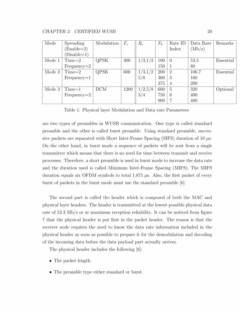
and frequency type spreading. Based on that, the standard specifies three modes of
operation. The modes are listed in table 1. The spreading factor for each type can
have a value of 2 for enable and 1 for disable option. One mode involves having time
and frequency spreading together. The second mode involve only time spreading. The
third mode option has no spreading technique selected. The modulation techniques
used along with each of those three modes is either Quadrature Phase Shift Keying
(QPSK) or Dual-Carrier Modulation (DCM) which is a variation of 16 Quadrature
Amplitude Modulation (16QAM). The supported data rates can be calculated as in
equation (6):
DataRate(Mb/s) =Fb
6∗ Sr (6)
Where Sr is the OFDM symbol length of 312.5 ns. Fb is the number of information
bits per hop frame which is found from the modulation code rate:
Fb = Rc ∗ Fc (7)
Fc is the coded bits per frame and Rc is the code rate listed in table 1.
The main functionality of the physical layer is to provide service to the MAC
layer and an interface to the wireless medium. The physical layer basic services are
to switch between receives and transmit mode as per MAC layer instructions. The
physical layer will handle the transportation of both control and data information. In
addition, the physical layer can provide the upper layers with status of the wireless
channel if its busy or free.
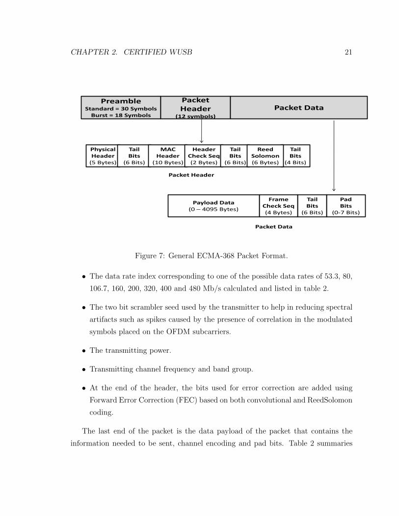
The physical layer will transmit information on the channel in packets. Each
packet is composed of three parts summarized in figure 7. The first part of the packet
is called the preamble for acquisition which is a predetermined fixed number of bits
that allow the receiver to detect the existence of a packet and to estimate the param-
eters used for accurate demodulation. Moreover, preamble time gives enough time
for any device to turn around from receive to transmit mode and vice versa. There
CHAPTER 2. CERTIFIED WUSB 20
Mode Spreading Modulation Fc Rc Fb Rate ID Data Rate Remarks(Enable=2) Index (Mb/s)(Disable=1)
Mode 1 Time=2 QPSK 300 1/3,1/2 100 0 53.3 EssentialFrequency=2 150 1 80
Mode 2 Time=2 QPSK 600 1/3,1/2 200 2 106.7 EssentialFrequency=1 5/8 300 3 160
375 4 200Mode 3 Time=1 DCM 1200 1/2,5/8 600 5 320 Optional
Frequency=2 3/4 750 6 400900 7 480
Table 1: Physical layer Modulation and Data rate Parameters
are two types of preambles in WUSB communication. One type is called standard
preamble and the other is called burst preamble. Using standard preamble, succes-
sive packets are separated with Short Inter-Frame Spacing (SIFS) duration of 10 µs.
On the other hand, in burst mode a sequence of packets will be sent from a single
transmitter which means that there is no need for time between transmit and receive
processes. Therefore, a short preamble is used in burst mode to increase the data rate
and the duration used is called Minimum Inter-Frame Spacing (MIFS). The MIFS
duration equals six OFDM symbols to total 1.875 µs. Also, the first packet of every
burst of packets in the burst mode must use the standard preamble [6].
The second part is called the header which is composed of both the MAC and
physical layer headers. The header is transmitted at the lowest possible physical data
rate of 53.3 Mb/s or at maximum reception reliability. It can be noticed from figure
7 that the physical header is put first in the packet header. The reason is that the
receiver node requires the need to know the data rate information included in the
physical header as soon as possible to prepare it for the demodulation and decoding
of the incoming data before the data payload part actually arrives.
The physical header includes the following [6]:
• The packet length.
• The preamble type either standard or burst.
CHAPTER 2. CERTIFIED WUSB 21
PreambleStandard = 30 Symbols
Burst = 18 Symbols
Packet Header
(12 symbols)
Packet Data
Physical Header
(5 Bytes)
TailBits
(6 Bits)
MACHeader
(10 Bytes)
HeaderCheck Seq(2 Bytes)
TailBits
(6 Bits)
TailBits
(4 Bits)
ReedSolomon(6 Bytes)
Packet Header
PadBits
(0-7 Bits)
TailBits
(6 Bits)
FrameCheck Seq(4 Bytes)
Payload Data(0 – 4095 Bytes)
Packet Data
Figure 7: General ECMA-368 Packet Format.
• The data rate index corresponding to one of the possible data rates of 53.3, 80,
106.7, 160, 200, 320, 400 and 480 Mb/s calculated and listed in table 2.
• The two bit scrambler seed used by the transmitter to help in reducing spectral
artifacts such as spikes caused by the presence of correlation in the modulated
symbols placed on the OFDM subcarriers.
• The transmitting power.
• Transmitting channel frequency and band group.
• At the end of the header, the bits used for error correction are added using
Forward Error Correction (FEC) based on both convolutional and ReedSolomon
coding.
The last end of the packet is the data payload of the packet that contains the
information needed to be sent, channel encoding and pad bits. Table 2 summaries

CHAPTER 2. CERTIFIED WUSB 22
the physical layer parameters used.
Function ValueConvolutional Encoding Code = 1/3 and Rates = 1/2, 5/8, and 3/4Subcarrier Modulation QPSK and DCMNumber of Sub-carriers 128Number of Data Carriers 100Number of Pilot Carriers 12Number of Guard Carriers 10Sub-Carrier Frequency Spacing 528 MhzOFDM Symbol Duration 312.5 ns
Table 2: Parameters of WUSB and Wimedia Wireless OFDM Symbol.
2.3 MAC Layer Channel
The MAC layer is a sub-layer of the data link layer and it’s main function is to pro-
vide wireless channel access mechanisms and addressing which allows several network
nodes to communicate within a network to provide unicast, multicast and broadcast
communication service. The MAC layer sits between the Logical Link Control (LLC)
sub-layer and the physical layer. WUSB is not considered to just have a separate
PAL layer on top of the Wimedia MAC layer. In fact, The MAC layer in WUSB de-
vices is not the same as the Wimedia MAC layer specified in ECMA-368 standard [6].
However, WUSB MAC layer uses the majority of the Wimedia MAC functionalities
as it will be explained in this section.
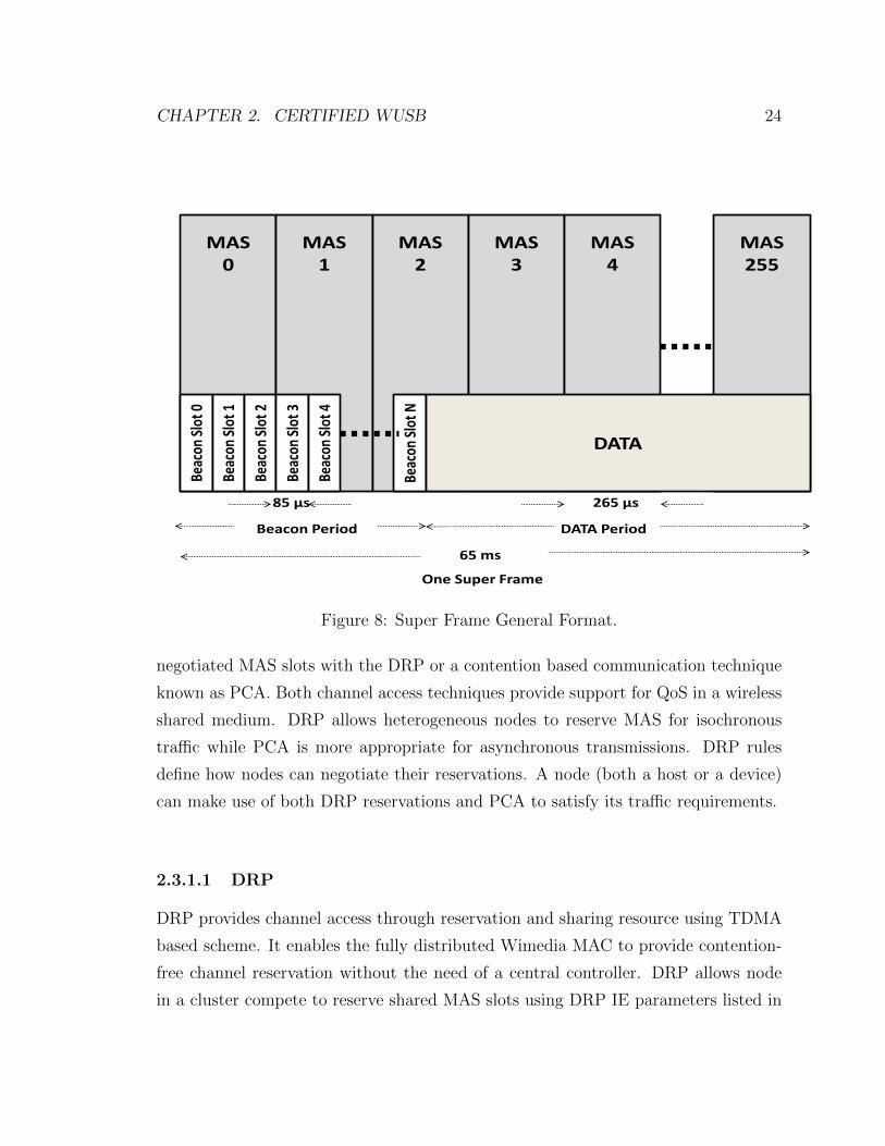
The wireless MAC layer channel; as specified ECMA-368 [6] and Wimedia stan-
dards [5]; is divided into continuous super frames. Each super frame is 65 ms long
and consisting of 256 Medium Access Slots (MASs) as show in figure 8. The su-
per frame can also be represented as a 16x16 matrix having 16 zones and each zone
contains 16 MAS. Super frames contain two main parts. One is called beacons and
the other is the data phase. Beaconing is the principal control mechanism used to
exchange information between devices. Beacons are transmitted at the start of each

CHAPTER 2. CERTIFIED WUSB 23
super frame and are transmitted at the lowest payload data rate of 53.3Mbps. The
beacon frame itself may be as short as approximately 15µs or as long as 63µs taking
up all the first 32 MAS slots in each super frame depending on the number of nodes
joining. The first two beacon slots are reserved and are not allocated by any node
since they are used for signaling purposes. The device first scans the wireless medium
for one super frame duration searching for any beacons. If no beacons found, then it
starts its own beaconing with six beacon slots including the signal slots. On the other
hand, if the device scanning finds existing beacons in the wireless medium, then those
signaling slots come into play. The signaling slots can be used to accommodate new
devices joining the existing cluster. For example, when a device has fixed number of
beacon slots allocated and used by existing neighbor device, the new device joining
the cluster wont find any empty slot to choose from. Using those two reserved slots, it
can randomly choose between the two slots to indicate to the device that it needs to
expand its list of beacon slots to expand the new device request to join. In addition,
every four super frames, the new device has to stop the use of the signaling slots to
allow other devices use the signaling slots if needed.
Each beacon slot contains one beacon frame which contains the different control
information data units called Information Elements (IEs) defined for that beacon.
Sometimes the IE requires the allocation of more than one beacon slot. The data
part that comes after the beacon period is where the WUSB MAC layer architecture
differs from the general Wimedia standard MAC layer standard. We are going to
summarize the architecture of both layouts in the next two sub sections.
2.3.1 Wimedia MAC Layer Channel
The Wimedia MAC combines both reservation based systems and priority contention
based channel systems [5]. In figure 9, each super frame in the channel consist of two
main portions sent continuously. The beacon period and the data transfer period.
Nodes in the cluster can access channel through the data transfer period, using either
CHAPTER 2. CERTIFIED WUSB 24
MAS0
MAS1
MAS2
65 ms
MAS3
MAS4
MAS255
265 µs85 µs
Beac
on S
lot 0
Beac
on S
lot 1
Beac
on S
lot 2
Beac
on S
lot 3
Beac
on S
lot N
Beac
on S
lot 4
Beacon Period
One Super Frame
DATA
DATA Period
Figure 8: Super Frame General Format.
negotiated MAS slots with the DRP or a contention based communication technique
known as PCA. Both channel access techniques provide support for QoS in a wireless
shared medium. DRP allows heterogeneous nodes to reserve MAS for isochronous
traffic while PCA is more appropriate for asynchronous transmissions. DRP rules
define how nodes can negotiate their reservations. A node (both a host or a device)
can make use of both DRP reservations and PCA to satisfy its traffic requirements.
2.3.1.1 DRP
DRP provides channel access through reservation and sharing resource using TDMA
based scheme. It enables the fully distributed Wimedia MAC to provide contention-
free channel reservation without the need of a central controller. DRP allows node
in a cluster compete to reserve shared MAS slots using DRP IE parameters listed in

CHAPTER 2. CERTIFIED WUSB 25
BeaconPeriod
DRP PCA DRPBeacon
PeriodPCA DRP
Super Frame N Super Frame N + 1
Figure 9: General Model of Wimedia MAC Layer Channel.
each beacon. The format of the DRP IE is explained in section 2.8.4. The reservation
process starts by having a node initiating the request in their beacon when its sent
to a target node. The target node has to make sure that the reservation request
wont cause any issues first. The target node will respond to a reservation request
either with Granted, Not Granted, or Pending. If granted then reservation process is
successful. If response was Not Granted, the target node would sensed that another
neighbor device already reserved the requested MAS slot and would cause a conflict.
In this case, the target node includes a DRP Availability IE in their beacon, which
gives the MAS availability for that device. This will help the source node to adjust
its reservation request in the next beacon interval according to the targets DRP MAS
availability IE. Finally, if the response for the request is Pending, it means that the

CHAPTER 2. CERTIFIED WUSB 26
target node needs more time to respond with a final answer to the source node. DRP
IE are kept in the beacons for a maximum of four super frames or until they get a
response for the request. In the case that there is a conflict during the reservation
request, both nodes that are asking for the same MAS will use both the Conflict
Tie-Breaker bit of the DRP IE and the beacon slot number of the device. The Con-
flict Tie-Breaker bit is set to a random value by the reservation source at the time of
reservation request. The two nodes will first compare each other Conflict Tie-Breaker
bit. If the two bits are the same, then the node with the smaller beacon slot number
wins and reserves the requested MAS slots. If the two Conflict Tie-Breaker bits are
different in value, then the node with the higher beacon slot number wins.
There are four different types of reservation can be done in a cluster of nodes:
• Hard reservation where only the reservation owner may initiate a frame trans-
mission (except for acknowledgements). Any unused time in the reservation
may explicitly be released for PCA access.
• Soft reservation where the reservation owner has priority access to the channel
without any delay at the start of each reservation block (contiguous portion of
the reserved channel time). If the owner leaves the channel free for a certain
interval of time, the rest of the nodes may contend for the channel using PCA
rules.
• Private reservation where the channel access rules are defined by the owner and
targets of the reservation. The Private Reservation is one of the major features
of the WiMedia architecture and is the principle means by which other MAC
protocols can share the UWB radio medium. For example, WUSB uses private
reservation which will be explained in section 2.3.2.
• Alien beacon where some MAS slots will be reserved and not used by the cluster
of node if there is another nearby cluster has those same MAS slots reserved.
This type of reservation will minimize the conflict or interference that might be
caused from having two neighbor clusters in the same wireless domain.
CHAPTER 2. CERTIFIED WUSB 27
Hard and private DRPs dont allow other types of traffic with different priorities.
Soft DRP has the option to provide traffic at the highest priority as well as guaran-
teed service for nodes sharing the channel. This option can be very helpful for urgent
security and medical applications in order to have the highest priority access, with
the Arbitration Inter-Frame Space (AIFS) set to zero. Hard and Private DRP can
release any unused time in the unsafe reservations. Host can signal to other users of
the super frame that we are prepared to relinquish MAS if necessary.
There are MAC policies put in place on the channel usage in order to have fair-
ness in the network and not have one client using all the channel bandwidth by itself.
A device can reserve a maximum of 112 MAS out of 256 units available within the
super frame without giving them up to other devices requesting slots. This means
that a device can set a maximum 112 MAS slot to SAFE mode where no one else can
reserve that. Any device can reserve more than 112 MAS only if free channel slots
are available. Those extra slots over 112 MAS will be set to UNSAFE mode. This
way the extra slots can be given away to any new device requesting those channel
slots. This way channel slots are used fairly in the network. So if a node sees the
unsafe bit set to 1 in the DRP IE portion, the node can send Relinquish Request IE
back to that source node asking to reserve those unsafe slots. The source node should
respond within 4 super frames by either granting those unsafe slots or changing the
status of the slot to SAFE mode instead.
Different applications might require different reservation block sizes and service
intervals within a super frame for their optimal operation. Column reservation is
used for video applications that require continuous time slot in order to achieve high
throughput. Row reservation is used for applications in need for low latency and small
buffering requirements. In order to have both kind of row and column reservations
exist, as per the Wimedia standard the largest number of continuous MAS blocks
that can be reserved in the same zone is eight and set to SAFE mode (see figure 10).

CHAPTER 2. CERTIFIED WUSB 28
Reserved Row 0
Reserved Row 1
0 1 2 3 4 5 6 7 8 9 10 11 12 13 14 15
Zones
Index
15
8
13
12
11
10
9
14
7
6
5
4
3
2
0
1
Bea
con
Zone
Prio
rity
1
Prio
rity
4
Prio
rity
4
Prio
rity
4
Prio
rity
4
Prio
rity
4
Prio
rity
4
Prio
rity
4
Prio
rity
4 Prio
rity
2
Prio
rity
2
Prio
rity
3
Prio
rity
3
Prio
rity
3
Prio
rity
3 Res
erve
d Co
lum
n
Res
erve
d Co
lum
n
Figure 10: MAS Allocation Rules.
Wimedia MAC standard compaction rules allow the maximum super frame uti-
lization by applying only when reservations are in SAFE mode:
• Rule 1: All row reservation must be as close to the bottom of the MAS table
as possible. The owner does not have to break its reservation block into two or
more smaller chunks to meet this requirement.
• Rule 2: All column reservation blocks must be contained in the top half of the
MAS table if possible. If not, then they should be as high up in the MAS table
as possible. Also, each reservation block in each zone must be moved up as high
in its zone as possible.
• Rule 3: While meeting Rule 2, when an option is available, a column-reservation

CHAPTER 2. CERTIFIED WUSB 29
device must try to allocate its column blocks in zones according to the prioritized
list of table 3 except for the Beacon zone 0. Priority 1 means the highest priority
and Priority 4 the lowest. Figure 10 shows the distribution of each priotity zone
in the MAS table.
Priority Zone1 82 4 or 123 2,6,10 or 144 1,3,5,7,9,11,13 or 15
Table 3: Zone priorities of Rule 3.
2.3.1.2 PCA
A channel access priority is computed and the nodes contend with other nodes for
the right to transmit via the shared channel based on Carrier Sense Multiple Access
with Collision Avoidance (CSMA/CA). PCA priority rules are derived from EDCA
802.11e. The difference is that PCA uses four priority classes including audio, video,
best effort and background while EDCA 802.11e uses seven priorities. The node im-
plementing PCA will start by sensing activity on the channel. If there is an activity
then the device will have to wait until the end of the activity. Once the channel is
sensed to be free, the node will wait an AIFS time plus a random time period called
the back-off slot. The AIFS value will depend on the type of the traffic, see table I.
The shorter the AIFS of the traffic class is, the higher the priority of the class. In
addition, each competing node may only use the medium for a limited period of time
before it has to give up the medium and allow others to contend for it. For voice, this
period is short since voice packets are not expected to contain as much information
as the other traffic types. On the other hand, video traffic gets the longest of four
MAS durations. Best effort and background traffic require two MAS slots.
The back-off value is uniformly distributed random integer number between zero
and the minimum contention window of the corresponding traffic class (Cmin), as

CHAPTER 2. CERTIFIED WUSB 30
listed in table 4. Once the back-off timer reaches zero count, it will transmit. If the
transmission is not successful, the contention window will be doubled and continues
doing so after every new collision of the frame and up until it reaches the maximum
value (Cmax).
Traffic Type AIFS Cmin CmaxVoice 19µs 3µs 255µsVideo 28µs 7µs 511µsBest Effort 46µs 15µs 1023µsBackground 73µs 15µs 1023µs
Table 4: Priority Parameters in Wimedia MAC
2.3.2 WUSB MAC Layer Channel
WUSB MAC takes some of main functionality of Wimedia MAC described before.
It also integrates the general model of the wired USB transaction process with the
wireless MAC layer. WUSB MAC is solely focused on reservation based network
access [9]. The PCA mechanism used in Wimedia MAC is set to an option mode and
disabled by default in the WUSB standard. In WUSB channel, each super frame is
divided into a beacon period and a data transfer period. The data period is reserved
via the beacon private DRP negotiations and based on the Wimedia MAC policies as
described in section 2.3.1.1. However, the difference in WUSB that the data period
consists of a sequence of Transaction Groups (TG). A transaction group contains
controller packet called Micro-scheduled Management Commands (MMC) and the
data time slots for data transmissions. As seen in figure 11, the WUSB channel after
each beacon consist of continuous linked MMC control packets which are transmitted
from the host and helps indentifying host information, pointers to the times when
each incoming and outgoing data slots must start. In addition, MMC contains a time
reference to the next MMC to indicate the next TG in sequence. Moreover, MMC
header contains channel timestamps which allows devices to synchronize it’s clocks
to each other. Therefore, the drift due to clock inaccuracy can be ignored since the
devices will re-synchronize themselves to a common clock reference at the start of
CHAPTER 2. CERTIFIED WUSB 31
every MMC.
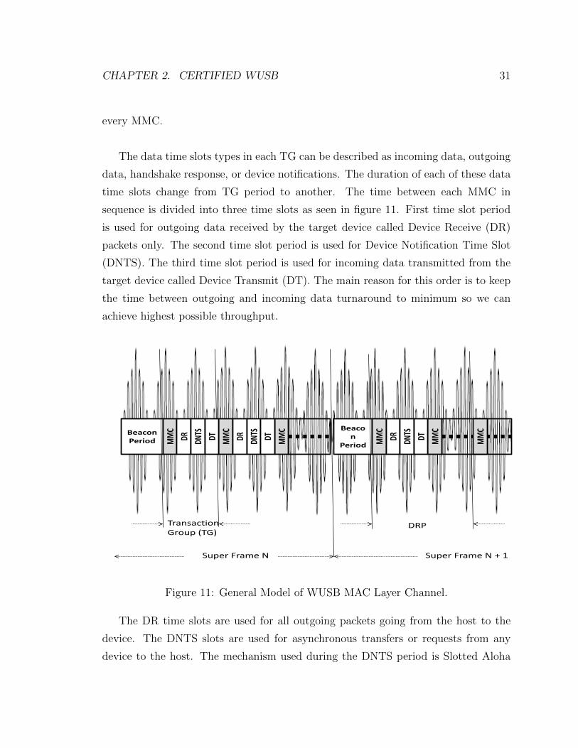
The data time slots types in each TG can be described as incoming data, outgoing
data, handshake response, or device notifications. The duration of each of these data
time slots change from TG period to another. The time between each MMC in
sequence is divided into three time slots as seen in figure 11. First time slot period
is used for outgoing data received by the target device called Device Receive (DR)
packets only. The second time slot period is used for Device Notification Time Slot
(DNTS). The third time slot period is used for incoming data transmitted from the
target device called Device Transmit (DT). The main reason for this order is to keep
the time between outgoing and incoming data turnaround to minimum so we can
achieve highest possible throughput.
BeaconPeriod
Beacon
Period
Super Frame N Super Frame N + 1
MMC
MMC
MMC
MMC
MMC
TransactionGroup (TG)
DR DNTS
DT DR DRDNTS
DNTS
DT DT
DRP
MMC
Figure 11: General Model of WUSB MAC Layer Channel.
The DR time slots are used for all outgoing packets going from the host to the
device. The DNTS slots are used for asynchronous transfers or requests from any
device to the host. The mechanism used during the DNTS period is Slotted Aloha
CHAPTER 2. CERTIFIED WUSB 32
Protocol. The DT time slots are used for all incoming packets going back from the
device to the host. The handshake acknowledgement response is only done during the
DT period to acknowledge the receiving of the data from the device perspective. The
host acknowledgement is done through the MMC control packets. Therefore, WUSB
has its own retransmission technique and doesnt use the Wimedia MAC Acknowl-
edgement policy so the acknowledgement policy field is set to No Ack in the WUSB
MAC header.
2.4 WUSB MAC Layer Main Features
2.4.1 Data Bursting
Data bursting is a mechanism that enables source node to transmit more than one
data packet per data phase and the destination node must provide information during
the handshake phase acknowledging that data was received. Data bursting option is
available for WUSB in order to help reduce significant packet overheads for wireless
transmission. The maximum allowed burst size is 16 packets. It can be used for
isochronous data transfer and bulk transfers.
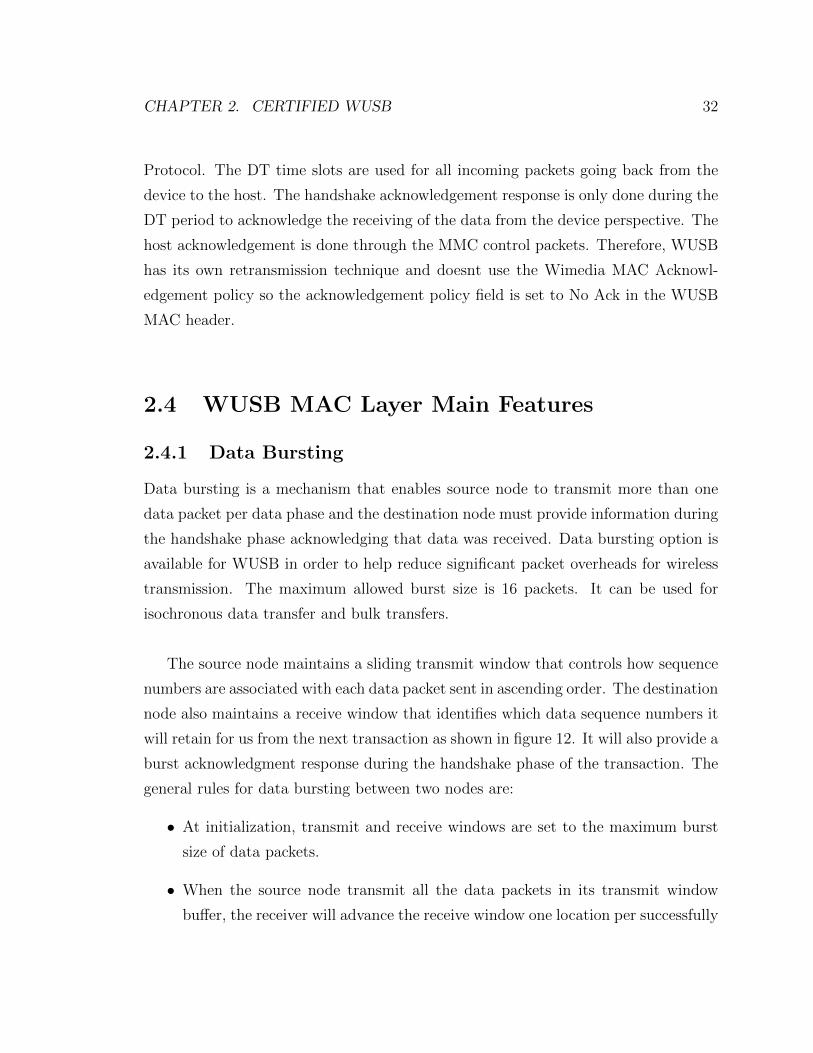
The source node maintains a sliding transmit window that controls how sequence
numbers are associated with each data packet sent in ascending order. The destination
node also maintains a receive window that identifies which data sequence numbers it
will retain for us from the next transaction as shown in figure 12. It will also provide a
burst acknowledgment response during the handshake phase of the transaction. The
general rules for data bursting between two nodes are:
• At initialization, transmit and receive windows are set to the maximum burst
size of data packets.
• When the source node transmit all the data packets in its transmit window
buffer, the receiver will advance the receive window one location per successfully
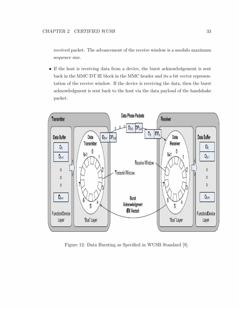
CHAPTER 2. CERTIFIED WUSB 33
received packet. The advancement of the receive window is a modulo maximum
sequence size.
• If the host is receiving data from a device, the burst acknowledgement is sent
back in the MMC DT IE block in the MMC header and its a bit vector represen-
tation of the receive window. If the device is receiving the data, then the burst
acknowledgment is sent back to the host via the data payload of the handshake
packet.
Figure 12: Data Bursting as Specified in WUSB Standard [9].

CHAPTER 2. CERTIFIED WUSB 34
2.4.2 Synchronization
There are two types of synchronization already done before in the ECMA-368 stan-
dard [6]. One is through the physical layer as part of the preamble synchronization
sequence at the start of each packet. The other synchronization method is done
through the Wimedia MAC standard by having all devices synchronize their clocks
in each super frame by using the timing information found in the beacons. In addi-
tion, a 12 µs Guard Time in addition to the 10 µs SIFS duration is added by each
device at the end of each reservation block. Moreover, the WUSB standard added
that all nodes in the cluster reset their internal clocks to zero at the beginning of
MMC header. So the WUSB host must provide a WUSB channel time stamp in each
MMC [9].
2.4.3 Resiliency Against Hidden Terminal Problem
A beacon slot is available for occupancy by a device only if in the last four super frames
the beacon slot was not reported as occupied by any of the transmitted or received
BPOIEs. This way when a host checks the BPOIE received, it checks the beacon
slot occupancy for a two-hop neighborhood. In addition when a negotiation process
starts asking to reserve MAS periods between two nodes, a two way negotiation
confirmation is done to make sure the new reserved period dont cause a conflict for
each node neighbors.

CHAPTER 2. CERTIFIED WUSB 35
2.5 WUSB Connection Setup
Authenticated
Unconnected
UnauthenticatedReconnecting
Connected
Device Notification
ReconnectNotification
ConnectionRequestFailed
ConnectionRequestSuccess
4 wayHandshakeSuccess
4 wayHandshakeStart
TrustTimeout
4 wayHandshakeFail
ReconnectSuccess
6 Retries Reached
Figure 13: UWSB Connection Setup State Diagram.
A host and device need to establish a logical connection through the wireless
medium. This connection setup needs to be done in a secure way before data commu-
nication starts and WUSB function starts to be used. The following states displayed
in figure 13 above will be explained during connection setup:
• Unconnected State: Devices reside in this state when they are not connected
to any devices or they failed to establish a connection to any neighbor host.
A device can only initiate connection request through listening to beacons and
find the DNTS period for asynchronous requests. A device stays in this state
until a specific WUSB host instructs the device to connect using the WUSB
transactions process by sending a ”Connect Acknowledgement” reply to the

CHAPTER 2. CERTIFIED WUSB 36
request. When the host sends back the successful acknowledgment to the new
device, it adds the new device to the list of unauthenticated device addresses
which will be prepared for the next state. However, at this point the device is
considered connected in general as per figure 13.
• Unauthenticated State: Before authenticated communication exchanged be-
tween host and device is not secured. The host will then complete a 4 way
handshake process to establish data packet encryption. After this step, both
device and host are ready to encrypt all data phase and handshake phase trans-
action packet transmissions. Finally, the host will send a request to load the cur-
rent key back to the device so that the device can authenticate WUSB Channel
broadcast packets like MMC packets. More on the authentication methodology
will be explained in the security section 2.10
• Authenticated State: The device enters this state when it passes all the authen-
tication requests. The device will be considered at this stage normal, connected,
authenticated and ready for any data transactions. The device will stay in this
phase as long as its host receives periodic MMC broadcasts greater than a ”Trust
Timeout” value of 4 seconds.
• Reconnecting State: This state is entered when either ”Trust Timeout” is
reached or the 4 way handshake authentication failed. The device will try
to connect again to the host via the DNTS period. The only difference between
the requests in this state than the unconnected state is that the requests done
here are secured. The device will transition to the unconnected state if the host
does not respond to the reconnect device notification attempts after 6 attempts.
2.6 WUSB Data Transactions
The data exchange happens between MMC blocks. The MMC command gives both
the sender and receiver a time stamp indication when they should start sending to
each other. When a host is ready to start sending data, it transmits first a MMC

CHAPTER 2. CERTIFIED WUSB 37
MMC Packet
MM
C H
eade
r
DR Dataout0
MMC Packet
MMC Packet
Time
DR
Per
iod
DN
TS P
erio
dD
T Pe
riod
MM
C H
eade
rD
R P
erio
dD
NTS
Per
iod
DT
Peri
od
MM
C H
eade
rD
R P
erio
dD
NTS
Per
iod
DT
Peri
od
DR Dataoutn
DNTS DNTS
DTDataHandShake
DTDataIn0
DTDataIn1
DTDataIn0
Host Outgoing Transaction
Host Incoming Transaction
= Host Transmission
= Device Transmission
Figure 14: UWSB Data Transaction.
command to allocate three blocks as shown in figure 14. First block period DR for
the burst of data is transmitted completely to the device. Then a short DNTS block
is allocated for any asynchronous notifications. Finally, the third block DT is used
by the device to complete the transmission of any control handshake command back
to the host. Note that if there is not enough time to have the DT stage completed by
the device in the first transaction, the host can allocate the handshake period in the
next MMC. On the other hand, when a device wants to send back either a single or
multiple burst of data, it waits for a MMC block that gives the device the time stamp
to start transmitting its data. The MMC command received by the host is used to
adjust the device transmit window and transmission rate. In this direction, the host
wont allocate any time for itself, it will only allocate time for the DNTS period then
the DT period used by the device as shown in the device transmission cycle in figure

CHAPTER 2. CERTIFIED WUSB 38
14. During the data phase time period, the host listens for incoming data packets.
It observes the sequence numbers of received data packets and advances its receive
window accordingly. The acknowledgement of which data packets the host received
without error is communicated back to the device in the next MMC command which
helps in saving channel time and protocol overheard. There are five types of data
transactions defined in WUSB standard [9]:
2.6.1 Bulk Data Transfers
Devices use the bulk transfer mode if they need a guarantee from WUSB to send large
amounts of data at variable data rate with no guarantees on bandwidth or latency.
The maximum allowed burst size is 16 packets. The maximum packet size for a packet
sent in burst mode is a value between 512 and 3584. The value should be a multiple
of 512 (i.e. 512, 1024, 1536, 2048, 2560, 3072 and 3584). Bulk data transfer can be
bi-directional between host and device.
2.6.2 Isochronous Data Transfers
Isochronous data transfer is used for applications that need guaranteed average con-
stant data rate and periodic data transfers with bounded delays. It also guarantees
data retries to achieve reliability of the wireless communication. Isochronous transfer
is always unidirectional but it can be bi-directional with two separate streams. The
maximum allowed burst size is 16 packets. The maximum packet size for a packet
sent in burst mode is 3584. Different handshake mechanism retries and buffering
choices had to be added to ensure the isochronous data transfer can be successful in
the high error-rate conditions of the wireless medium.
2.6.3 Interrupt Data Transfers
Interrupt data transfer are unidirectional stream pipes of small amount of data with
guaranteeing high reliability. This is done by guaranteeing retries during the service
period if delivery of the data fails. This data transfer requires achieving the lowest

CHAPTER 2. CERTIFIED WUSB 39
latency. The maximum allowed burst size is 1 packet. The maximum packet size for
a packet sent is 1024 bytes.
2.6.4 Control Data Transfers
Control data transfer used to transfer WUSB protocol commands for device initial-
ization and device management. Control data packets have a fixed data payload size
of 512 bytes and have a maximum burst size of one. The delivery of control data
packets are best effort based. Control packets are essentially used for the purpose of
controlling traffic flow from devices to the cluster host and its main types sent in the
data payload part are:
• Acknowledgements: they can be either an immediate acknowledgement to a
single data burst or a burst acknowledgment for more than one data burst.
This data indicates that a control transfer has been completed.
• Negative Acknowledgement (NAK) indicates that the transfer has not com-
pleted the action requested in the payload data portion.
• STALL is a handshake code indicates that the transfer has an error that prevents
it from completing the communication.
2.6.5 Asynchronous Device Notification Transfers
Device notification messages are asynchronous and happens during the DNTS time
period per transaction group. Those messages are always sent from the devices in
the cluster to the host. The host schedules those DNTS periods randomly in each
transaction group communication. The maximum allowable data payload for a device
notification message is 32 bytes and the messages must always be transmitted at the
PHY base signaling rate. The maximum duration of time slot for a maximum sized
notification slot is 26 µs.

CHAPTER 2. CERTIFIED WUSB 40
2.7 WUSB Bandwidth Reservation Policy
On top of the Wimedia MAC policies specified in section 2.3.1.1, WUSBS defines
extra limits depending on the type of data transaction is happening to allow fair
bandwidth distribution among devices.
Any WUSB aware MAC node can have a safe MAS reservation of 16 MAS periods
”MAX WUSB CHANNEL”as defined in table 5. When that node becomes a host to
cluster and connects to at least one device, the limit of safe MAS reservation increase
up to ”ASYNC MAC” of 64 MAS periods. However, this number might change de-
pending on the type of the data transfer used.
If reservation is done for bulk, control or interrupt type of data transfers and no
isochronous data transfer exists in the same cluster. The maximum limit of safe MAS
periods is noted as SafeForAsync and calculated as:
SafeForAsync = ASYNC MAC
If reservation is done for bulk, control or interrupt type of data transfers and
isochronous data transfer exists in the same cluster:
SafeForAsync = max(ASYNC MIN, ASYNC MAX - SafeForPeriodic)
The value of SafeForPeriodic for isochronous safe reservation is found by calculat-
ing the number of MAS that are needed to transfer the periodic isochronous data over
”MIN PERIODIC RATE” listed in table 5 and based on maximum service interval,
burst size and packet size.
Therefore, for any cluster the maximum number of MAS needed for safe reserva-
tion is:

CHAPTER 2. CERTIFIED WUSB 41
Max MAS Limit for a cluster = min(112, SafeForPeriodic + SafeForAsync)
Prameter ValueMAX WUSB CHANNEL 16ASYNC MAX 64ASYNC MIN 16MIN PERIODIC RATE 200 Mbps
Table 5: WUSB Bandwidth Reservation Policy Parameters.
2.8 Packet Formats
2.8.1 MAC General Header
The MAC header is specified in ECMA-368 standard and its used in Wimedia as well
as WUSB after the physical header. The MAC header is 10 bytes in fixed length and
its five components are listed below and summarized in figure 15
• Frame Control Information:
– Reserved field of 2 bits.
– Retry bit is set to 1 in any data or command packet retransmissions.
– Frame subtype is used to assist a receiver device in the proper processing
of received packets. For MMC packets, its set to 1110 value
– Frame type is the type of packet sent as listed in table 6.
Packet Type ValueBeacon Packet 0Control Packet 1Command Packet 2Data Packet 3Aggregated Data Packet 4Reserved 5-7
Table 6: Packet Type Field Encoding.

CHAPTER 2. CERTIFIED WUSB 42
ACK Policy Type ValueNo-ACK 0Imm-ACK 1B-ACK 2B-ACK Request 3
Table 7: ACK Policy Field Encoding.
– ACK policy field is set to the type of acknowledgement requested by the
transmitting node. The values for this field is set in table 7 below
– Secure bit is set to 1 to enable secure encapsulated packet.
– Protocol version field is set to zero in ECMA-368 standard.
• DestAddr is the destination address of the target destination of the packet. The
field can specify single device for unicast packet, a group of devices for multicast
packet or all devices for a broadcast packet.
• SrcAddr is the IP address of the transmitting or source node.
• Sequence Control field is 2 bytes containing the sequence number of the data
block and the fragment number within each sequence. The ”More Fragments”
field is set to zero to indicate that the current fragment is the final fragment
of the current sequence. Otherwise its set to 1 to indicate to the destination
device to expect another fragment.
• Access Information has three blocks:
– Access Method bit is set to 1 in all packets transmitted via private DRP
in WUSB.
– More Frames bit is set to 0 if the transmitter will not send further packets
to the same device destination. Otherwise it is set to 1.
– Duration field is set to an expected medium busy interval after the packet
header and used to update the Network Allocation Vector (NAV)
.

CHAPTER 2. CERTIFIED WUSB 43
PreambleStandard = 30 Symbols
Burst = 18 Symbols
Packet Header
(12 symbols)
Packet Data
Physical Header
(5 Bytes)
TailBits
(6 Bits)
MACHeader
(10 Bytes)
HeaderCheck Seq(2 Bytes)
TailBits
(6 Bits)
TailBits
(4 Bits)
ReedSolomon(6 Bytes)
Reserved(2 Bits)
FrameControl
(2 Bytes)
DestAddr(2 Bytes)
SrcAddr(2 Bytes)
SequenceControl
(2 Bytes)
AccessInfo
(2 Bytes)
Reserved(1 Bit)
MoreFragments
(1 Bit)
SequenceNumber(11 Bits)
FragmentNumber(3 Bits)
Retry(1 Bit)
FrameSubtype(4 Bits)
FrameType
(3 Bits)
ACK Policy(2 Bits)
Secure(1 Bit)
ProtocolVersion(3 Bits)
AccessMethod(1 Bit)
MoreFrames(1 Bit)
Duration(14 Bits)
Figure 15: MAC Header General Format.
2.8.2 Beacon Packet
Beacons always contain a standard preamble and are sent at the lowest data rate
of 53.3 Mbps. As noticed from figure 16 that packet start with standard preamble
and packet header then the beacon payload is encoded. The last two slots of guard
and SIFS time are delays used after each beacon to minimize the effect of clock drift.
Therefore, the maximum available duration for beacon packet transmission is
(85 µs) - (Guard Time) - (SIFS) = 63 µs
The destination address is set to the broadcast address in the packet header part.
The beacon payload contains beacon parameters and different beacon related IEs.
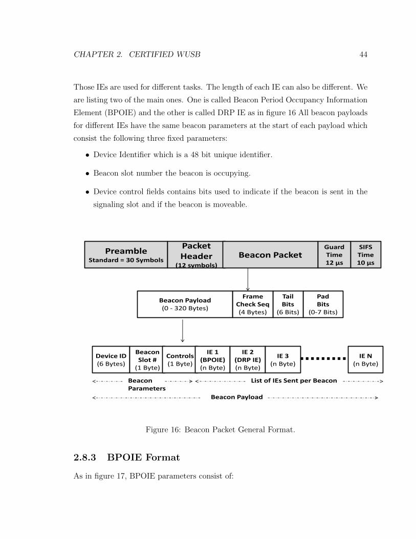
CHAPTER 2. CERTIFIED WUSB 44
Those IEs are used for different tasks. The length of each IE can also be different. We
are listing two of the main ones. One is called Beacon Period Occupancy Information
Element (BPOIE) and the other is called DRP IE as in figure 16 All beacon payloads
for different IEs have the same beacon parameters at the start of each payload which
consist the following three fixed parameters:
• Device Identifier which is a 48 bit unique identifier.
• Beacon slot number the beacon is occupying.
• Device control fields contains bits used to indicate if the beacon is sent in the
signaling slot and if the beacon is moveable.
PreambleStandard = 30 Symbols
Packet Header
(12 symbols)
Beacon Packet
PadBits
(0-7 Bits)
TailBits
(6 Bits)
FrameCheck Seq(4 Bytes)
Beacon Payload(0 - 320 Bytes)
GuardTime12 µs
SIFSTime10 µs
Device ID(6 Bytes)
Beacon Slot #
(1 Byte)
Controls(1 Byte)
IE 1(BPOIE)(n Byte)
BeaconParameters
List of IEs Sent per Beacon
Beacon Payload
IE 2(DRP IE)(n Byte)
IE 3(n Byte)
IE N(n Byte)
Figure 16: Beacon Packet General Format.
2.8.3 BPOIE Format
As in figure 17, BPOIE parameters consist of:
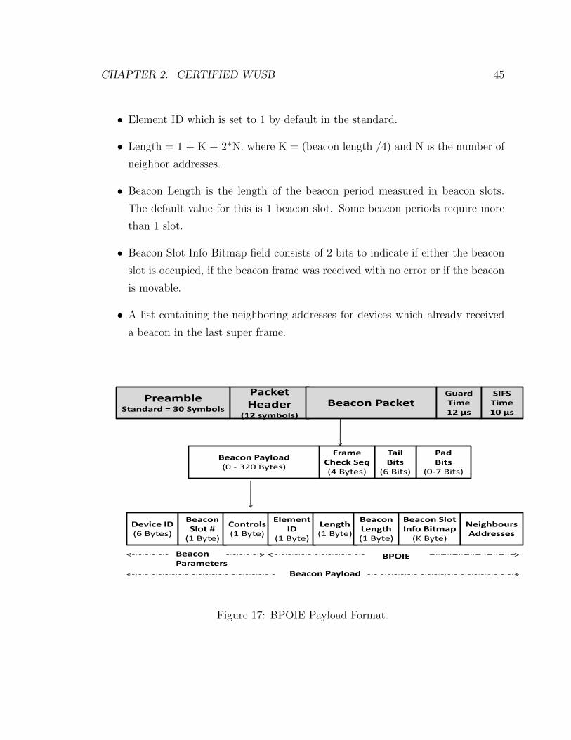
CHAPTER 2. CERTIFIED WUSB 45
• Element ID which is set to 1 by default in the standard.
• Length = 1 + K + 2*N. where K = (beacon length /4) and N is the number of
neighbor addresses.
• Beacon Length is the length of the beacon period measured in beacon slots.
The default value for this is 1 beacon slot. Some beacon periods require more
than 1 slot.
• Beacon Slot Info Bitmap field consists of 2 bits to indicate if either the beacon
slot is occupied, if the beacon frame was received with no error or if the beacon
is movable.
• A list containing the neighboring addresses for devices which already received
a beacon in the last super frame.
PreambleStandard = 30 Symbols
Packet Header
(12 symbols)
Beacon Packet
PadBits
(0-7 Bits)
TailBits
(6 Bits)
FrameCheck Seq(4 Bytes)
Beacon Payload(0 - 320 Bytes)
GuardTime12 µs
SIFSTime10 µs
Device ID(6 Bytes)
Beacon Slot #
(1 Byte)
Controls(1 Byte)
Element ID
(1 Byte)
Length(1 Byte)
BeaconLength(1 Byte)
Beacon SlotInfo Bitmap
(K Byte)
NeighboursAddresses
BeaconParameters
BPOIE
Beacon Payload
Figure 17: BPOIE Payload Format.

CHAPTER 2. CERTIFIED WUSB 46
2.8.4 DRP IE Format
DRP IE parameters are used for MAS reservation mechanism for negotiations pur-
poses as in figure 18 which consists of:
• Element ID which is set to 9 by default in the standard.
• Length = 4 + 4*N. where N is the number of neighbor addresses.
• DRP control fields.
• IP Address: the address is set to the target destination device.
• DRP allocation fields: These are the MAS slots index location that is requested
for reservation. Each field consists of two 16 bit values. The first value is called
Zone Bitmap which identifies one of the 16 zones in the super frame. The second
value is called MAS Bitmap which identifies one of the 16 MAS slots in a zone.
The DRP control fields as in figure 18 are identified as following:
• Safe/Unsafe field which indicates if the MAS slot is safely reserved so no other
device can ask for it or if its unsafely reserved which means that other devices
can overwrite that slot and take it.
• Conflict Tie Breaker bit which its a randomly chosen bit used to break a reser-
vation conflict between two devices.
• Owner: this field indicates if the device sending this IE is the owner of the
request or not.
• Reservation Status bit indicates if the reservation is successful or under a conflict
situation.
• Reason Code value can be either accepted, in conflict, pending, denied, or
modified.
• Stream Index field indicates which data stream is using the reservation.
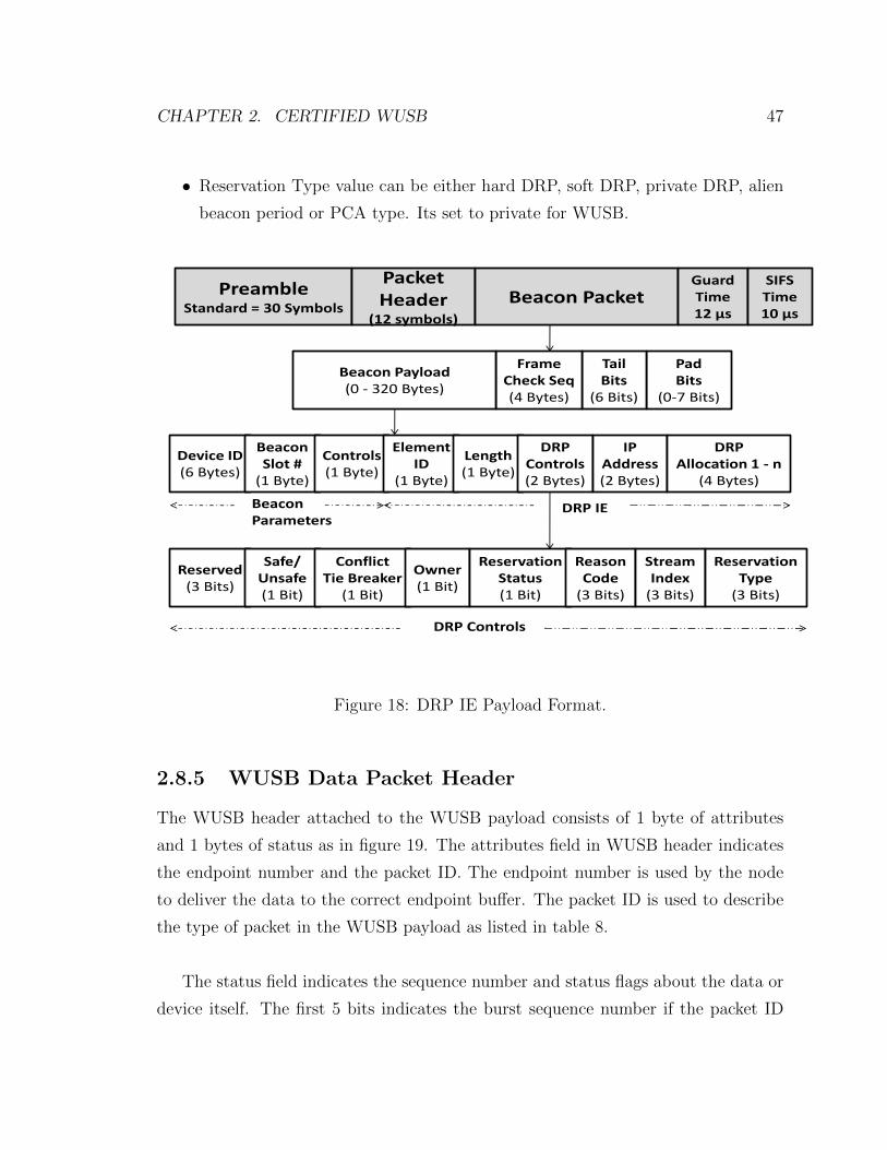
CHAPTER 2. CERTIFIED WUSB 47
• Reservation Type value can be either hard DRP, soft DRP, private DRP, alien
beacon period or PCA type. Its set to private for WUSB.
PreambleStandard = 30 Symbols
Packet Header
(12 symbols)
Beacon Packet
PadBits
(0-7 Bits)
TailBits
(6 Bits)
FrameCheck Seq(4 Bytes)
Beacon Payload(0 - 320 Bytes)
GuardTime12 µs
SIFSTime10 µs
Device ID(6 Bytes)
Beacon Slot #
(1 Byte)
Controls(1 Byte)
Element ID
(1 Byte)
Length(1 Byte)
DRP Controls(2 Bytes)
BeaconParameters
DRP IE
IPAddress(2 Bytes)
DRP Allocation 1 - n
(4 Bytes)
Reserved(3 Bits)
Safe/Unsafe(1 Bit)
ConflictTie Breaker
(1 Bit)
Owner(1 Bit)
ReservationStatus(1 Bit)
ReasonCode
(3 Bits)
StreamIndex
(3 Bits)
ReservationType
(3 Bits)
DRP Controls
Figure 18: DRP IE Payload Format.
2.8.5 WUSB Data Packet Header
The WUSB header attached to the WUSB payload consists of 1 byte of attributes
and 1 bytes of status as in figure 19. The attributes field in WUSB header indicates
the endpoint number and the packet ID. The endpoint number is used by the node
to deliver the data to the correct endpoint buffer. The packet ID is used to describe
the type of packet in the WUSB payload as listed in table 8.
The status field indicates the sequence number and status flags about the data or
device itself. The first 5 bits indicates the burst sequence number if the packet ID
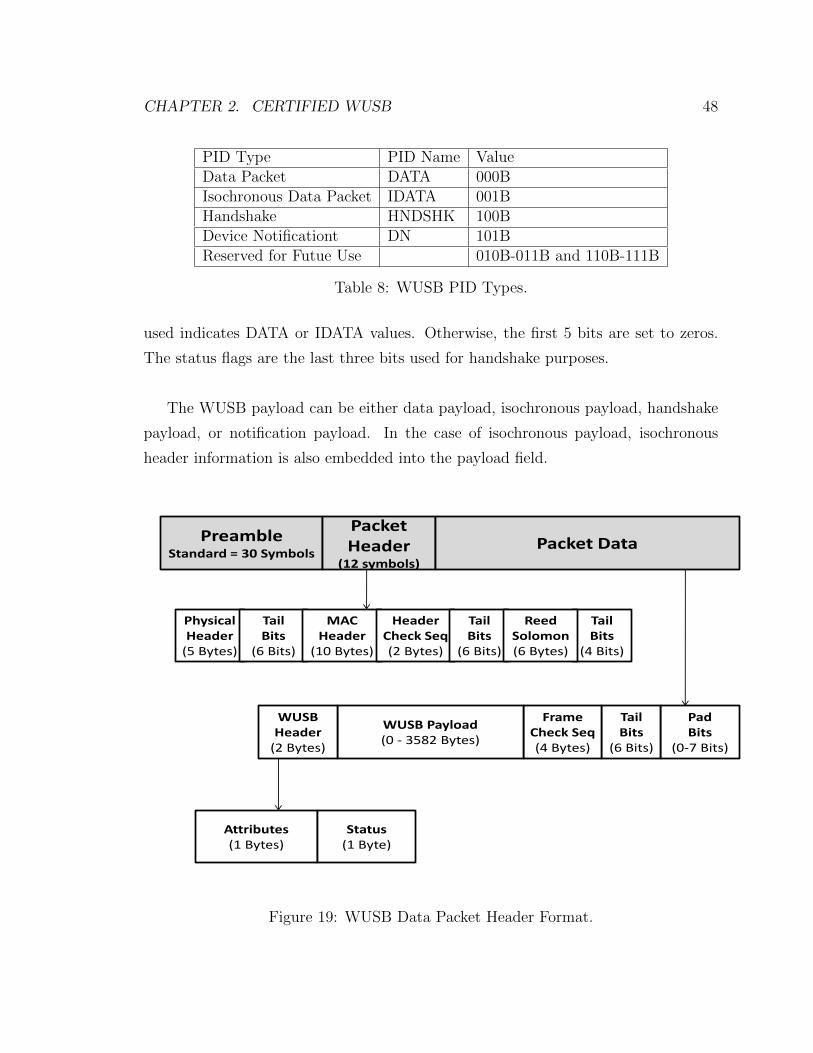
CHAPTER 2. CERTIFIED WUSB 48
PID Type PID Name ValueData Packet DATA 000BIsochronous Data Packet IDATA 001BHandshake HNDSHK 100BDevice Notificationt DN 101BReserved for Futue Use 010B-011B and 110B-111B
Table 8: WUSB PID Types.
used indicates DATA or IDATA values. Otherwise, the first 5 bits are set to zeros.
The status flags are the last three bits used for handshake purposes.
The WUSB payload can be either data payload, isochronous payload, handshake
payload, or notification payload. In the case of isochronous payload, isochronous
header information is also embedded into the payload field.
PreambleStandard = 30 Symbols
Packet Header
(12 symbols)
Packet Data
PadBits
(0-7 Bits)
TailBits
(6 Bits)
FrameCheck Seq(4 Bytes)
WUSB Payload(0 - 3582 Bytes)
Attributes(1 Bytes)
Status(1 Byte)
WUSBHeader
(2 Bytes)
Physical Header
(5 Bytes)
TailBits
(6 Bits)
MACHeader
(10 Bytes)
HeaderCheck Seq(2 Bytes)
TailBits
(6 Bits)
TailBits
(4 Bits)
ReedSolomon(6 Bytes)
Figure 19: WUSB Data Packet Header Format.
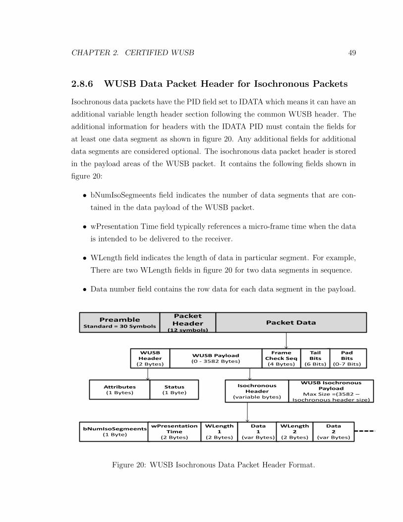
CHAPTER 2. CERTIFIED WUSB 49
2.8.6 WUSB Data Packet Header for Isochronous Packets
Isochronous data packets have the PID field set to IDATA which means it can have an
additional variable length header section following the common WUSB header. The
additional information for headers with the IDATA PID must contain the fields for
at least one data segment as shown in figure 20. Any additional fields for additional
data segments are considered optional. The isochronous data packet header is stored
in the payload areas of the WUSB packet. It contains the following fields shown in
figure 20:
• bNumIsoSegmeents field indicates the number of data segments that are con-
tained in the data payload of the WUSB packet.
• wPresentation Time field typically references a micro-frame time when the data
is intended to be delivered to the receiver.
• WLength field indicates the length of data in particular segment. For example,
There are two WLength fields in figure 20 for two data segments in sequence.
• Data number field contains the row data for each data segment in the payload.
PreambleStandard = 30 Symbols
Packet Header
(12 symbols)
Packet Data
PadBits
(0-7 Bits)
TailBits
(6 Bits)
FrameCheck Seq(4 Bytes)
WUSB Payload(0 - 3582 Bytes)
Attributes(1 Bytes)
Status(1 Byte)
WUSBHeader
(2 Bytes)
Isochronous Header
(variable bytes)
WUSB Isochronous Payload
Max Size =(3582 –Isochronous header size)
bNumIsoSegmeents(1 Byte)
wPresentation Time
(2 Bytes)
WLength1
(2 Bytes)
Data1
(var Bytes)
WLength2
(2 Bytes)
Data2
(var Bytes)
Figure 20: WUSB Isochronous Data Packet Header Format.
CHAPTER 2. CERTIFIED WUSB 50
2.8.7 MMC Packet
MMC control packets are always sent at the lowest data rate of 53.3 Mbps. The
packet is transmitted using secure packet encapsulation with the ”Encryption Offset”
field in the security header set to the length of the MMC payload. The MMC packet
consists of MMC header and MMC payload as in figure 21
MMC header is 10 bytes in length and composed of the following elements:
• WUSB Application Code: This unique code identifies the WUSB technology
and is set in the standard to 0100H
• MMC Code: another unique identifier set to 01H in the standard to indicate
the MMC Command type.
• Next MMC Time: this indicates the micro-seconds duration number from the
beginning of this MMC to the beginning of the next MMC packet.
• Reserved field should be set for zeros for 2 bytes duration.
• Channel Time Stamp: its the channel time communicated by the host which
contains a 24 bit value that indicates when MMC was transmitted. The time
stamp value consists of two parts. One part is (1/8)th millisecond 17 bit value
that wraps to zero after reaching a value of all 1s. The second part is a mi-
crosecond counter that counts from 0 to 124. Each time the microsecond value
raps around from 124 to zero, the (1/8)th millisecond value increments. The
accuracy of the host clock is +/- 40 nanoseconds.
The MMC payload consists of one or more IEs which are used to let the devices
know what to expect next during the communication. One of the most common used
IE is the WUSB Channel Time Allocation (WCTA) which contains channel allocation
blocks and as summarized in figure 21. It has the following elements:
• Length: 1 byte field indicating the length of the WCTA IE.

CHAPTER 2. CERTIFIED WUSB 51
• IE Identifier: the field indicates the type of the IE used in the MMC packet.
For WCTA type, the standard uses the value 80H.
• DR block consists of array of block allocation times for 1 or more devices that
are expecting data to be received.
• DNTS field is used for asynchronous transfer and consists of N slots where any
device can access.
• DT block consists of array of block allocation times for 1 or more devices that
are expecting data to be transmitted.
PreambleStandard = 30 Symbols
Packet Header
(12 symbols)
MMC Packet
PadBits
(0-7 Bits)
TailBits
(6 Bits)
FrameCheck Seq(4 Bytes)
MMC Payload(0 - 3574 Bytes)
SIFSTime10 µs
WUSBApplication Code
(2 Bytes)
MMC Code
(1 Byte)
Next MMC Time
(2 Bytes)
MMC Header
ChannelTime Stamp
(3 Bytes)
Length(1 Byte)
IE Identifier(1 Byte)
DR BlockDevice 0(4 Bytes)
MMC Payload
MMCHeader
(10 Bytes)
Reserved(2 Bytes)
DR BlockDevice m(4 Bytes)
DNTS(4 Bytes)
DT BlockDevice 0(4 Bytes)
DT BlockDevice n(4 Bytes)
Out/DR Period In/DT Period
TG
Figure 21: MMC Packet Format.
CHAPTER 2. CERTIFIED WUSB 52
2.9 Power Management
During the life time of the wireless channel, there exists period where no data transfer
activity is happening between two nodes within a cluster. Therefore, WUSB standard
introduces two ways to save node power consumption to increase their life time.
Devices and host can use both sleep mode and master MMC in their cluster.
• Sleep Mode: Host or devices can go into sleep mode where they dont send any
communication to the channel. The host has the ability to send a command
to certain devices in its cluster to ask them to go into sleep mode if there is
no more data transfer. At the same time, device can send back a notification
interrupt during the DNTS period indicating their intention to go into sleep
mode. The power hibernation mode for the host is critical since it will turn
down the channel and no more data transfer within its cluster.
• Master MMC: The master MMC concept has been introduced in the latest
version of WUSB standard revision 1.1 [9]. The master MMC format is the
same as the normal MMC except that its less frequent than the regular MMC
frequency where the maximum number of allowed master MMC within a super
frame is 16. This way it helps the host track transaction within the channel with
reducing the MMC commands. As a result, It reduces the power consumptions
that are used to transmit and receive those MMC commands.

CHAPTER 2. CERTIFIED WUSB 53
2.10 Security
WUSB has the security bit in the Wimedia MAC header enabled by default. It uses
most of the security feature that Wimedia MAC already provides. The WUSB packet
will always have extra secure fields that are going to be used for authentication and
encryption purposes as in figure 22 where few fields added in the payload data field
for WUSB MAC Packet. The secure fields consist of the following components:
• Temporal Key Identifier (TKID) field holds either a single or group temporal
key identifiers that identifies which of the internally stored keys are used to
encrypt the WUSB payload.
• Encryption Offset field indicates the offset from the beginning of the WUSB
payload where encryption starts. This feature is useful if not all the payload
portion needs to be encrypted.
• Secure Frame Number (SFN) field is a 48 bit counter that is incremented for
every transmitted packet which insures that the receiver wont receive a repeat
of the previous packet. This way it provides security against the replay attack.
• Message Integrity Code (MIC) field is used to provide authentication of the
packet.
The process of securing each packet between any transmitter and receiver should
go through main security methods. The association method is only added in the
WUSB standard [9]. The encryption and authentication methods are used from the
Wimedia MAC standard [5].

CHAPTER 2. CERTIFIED WUSB 54
PreambleStandard = 30 Symbols
Packet Header
(12 symbols)
Packet Data
PadBits
(0-7 Bits)
TailBits
(6 Bits)
FrameCheck Seq
(4 Bytes)
WUSB Payload
(0 - 3582 Bytes)
Attributes(1 Bytes)
Status(1 Byte)
WUSBHeader(2 Bytes)
Physical Header
(5 Bytes)
TailBits
(6 Bits)
MACHeader
(10 Bytes)
HeaderCheck Seq(2 Bytes)
TailBits
(6 Bits)
TailBits
(4 Bits)
ReedSolomon(6 Bytes)
MIC(8 Bytes)
SFN(6 Bytes)
EncOffset(2 Bytes)
Rsrvd(1 Bytes)
TKID(3 Bytes)
Figure 22: Security fields addition in WUSB MAC Packet.
2.10.1 Association Method
The first critical part in establishing a secure connection between two nodes is sharing
a master key that will be used in the authentication process later. This is a secret
128 bit key that can be established by either of three ways in WUSB.
• Use of a physical USB cable connection first to make sure that two devices are
connected in a secure way to share the master key. Then disconnecting the
physical cable and initiating new connection in the wireless medium.
• Use of numerical verification. It is based on the DiffieHellman protocol, which
is a method of establishing a shared secret key between two parties over an
insecure medium.
CHAPTER 2. CERTIFIED WUSB 55
• Near Field Communication (NFC) where the host and the device are brought to
very close proximity of each other (less than 10 cm). This property of NFC that
allows communication to take place only in close distance to provide protection
against man in the middle attacks.
2.10.2 Authentication Method
Once the association is established and master keys for different devices are shared,
devices can then initiate a four way handshaking sequence. During the four way
handshake, the device will use the shared master keys along with the device address
and a randomly generated number, it creates temporal key and stores it in the TKID
secure field in the WUSB packet payload. The temporal keys can be either single
between two peers or group type for broadcast and multicast use. Then if the security
bit is enabled in the MAC header, the receiver device will check the TKID frame to
make sure it matches one of the installed single or group temporal keys. If there is no
match found, the handshake process will be ignored and authentication will fail. If
there is a match found, the transmitter and receiver will use the MIC field to match
both outgoing and incoming message to insure the integrity of it and prevent the man
in the middle security attack. Once the packet is authenticated, the device will check
against replay attack by making sure that the replay counter is less than the SFN
field in the WUSB payload.
2.10.3 Encryption Method
Encryption is important in wireless networks to help prevent attackers from decrypt-
ing information sent in the packet payload. This method is done for each sent packet.
The encryption standard used in WUSB is called Advanced Encryption Standard
(AES)-128 where its based on one block of 128 bits. This is a symmetric encryption
algorithm that uses the AES counter block and Cipher Block Chaining Message Au-
thentication Code (CBC) to create a robust stream cipher that can be used to provide
integrity and encryption. Therefore, the complete encryption method used is called
AES-128 Counter with CBC-MAC (CCM).
Chapter 3
Related Work
Related literature on Wimedia and Certified WUSB UWB are reviewed. We are go-
ing to divide the literature research into Wimedia related work and Certified WUSB
related. The reason for listing the work for both standards is that Certified WUSB
related research found is little and most of the main functionality of WUSB is based
on the Wimedia standard.
3.1 Wimedia Related Work
3.1.1 DRP Reservation Based Only
One of those papers suggested a bi-dimensional markov chain model and argues that
embedded markov chain assumes that packet departures happen evenly distributed
in time which is not the case for Wimedia MAC since its not centrally controlled [10].
Their bi-dimensional method calculates the probability for the number of packets in
queue, where one dimension is for number of packets and the other is for packet ser-
vice point in the super frame. The allocation of the second dimension is determined
by the slot reservation pattern used by DRP. The paper only models the expected
delay at DRP option of Wimedia theoretically under different reservation patterns.
56

CHAPTER 3. RELATED WORK 57
Their suggested analytical model to find the expected the average delay using pre-
defined DRP patterns was verified with In-house simulations. In-house simulations
were done on three DRP reservation predefined patterns by using a fixed packet size of
1500 Bytes and bit speed rate of 400Mbps. This paper didnt specify the DRP option
type simulated and the simulator used. Moreover, it didnt take into consideration in
their analytical model, the data burst feature by only relying on immediate ACK for
each packet sent.
The second paper takes into consideration the shadowing effect in indoor environ-
ment and models the system as a discrete-time single server queue with devices not
in service period. The analytical model estimated the network delay represented by
Quasi Birth and Death (QBD) process and solved by a matrix geometric approach
[11], [12]. The proposed theoretical model was based on vacation queuing model
where the interval between two reservation periods is regarded as the vacation peri-
ods of the two nodes. The theoretical analysis was verified by comparing the results
to simulations results from an implemented simulator written in Python language.
The simulations were based on 2000 bytes size packets. The two papers analyzed
both hard and soft DRP option of Wimedia considering the characteristics of the
time varying UWB channels but only numerically. They found that soft DRP incurs
longer delays than hard DRP. They also found out that soft DRP patterns are more
sensitive to the variation in reservation patterns. However, the two papers didnt take
into account the data bursting feature of Wimedia.
Another paper evaluated the performance of DRP in Wimedia MAC by follow-
ing the Markovian Arrival Process (MAP) with different phase type distributions for
various service times and applying the Matrix Geometric Method (MGM) technique.
This paper calculated the probability mass function for the number of packets and
the cumulative distribution function for packets waiting time in the DRP queue. The
theoretical results were also compared to OPNET software simulation results [13].
The simulation was run using 5 nodes and on bit rate speed of 480 Mbps. They com-
pared the results using a very large packet size of 15250 bytes which is larger than

CHAPTER 3. RELATED WORK 58
the maximum size of 4096 bytes used in the Wimedia standard. The work also didnt
specify the DRP option used and didnt compare it to PCA as well. In Addition, it
didnt use the data burst feature in the analytical model and simulation.
There were also several papers that studied and proposed new methods for chan-
nel allocation for DRP in the super frame. The paper in [14] proposed a new resource
allocation method to avoid collisions between nodes competing for reservation. This
method is based on having devices maintain sending and receiving tables to track
activities in the neighborhood. In addition, they proposed that bandwidth is allo-
cated for video traffic based on traffic prediction using Normalized Least Mean Square
(NLMS) algorithm. In-house simulations were based on using 6 MPEG-6 video traces
to analyze the proposed allocation methods. However, those were simulations didnt
compare with the actual performance of the current DRP reservations methods in the
standard and how it improves the utilization of the network as the paper suggest.
Two distributed reservation algorithms were also suggested for DRP Wimedia in
[15]. One algorithm is called first-fit Algorithm. The first-fit algorithm starts from
the first empty place in the super frame in the increasing order of the column priori-
ties in binary search manner. It first looks for available MAS size then it checks the
delay requirement for its video flow. The second algorithm is called best-fit algorithm.
Best-fit Algorithm starts from the column that has the closest natural service interval
to the flows requested delay and searches through the super frame from there. The
simulations were done in NS-2 with using highest bit rate of 480 Mbps. In their sim-
ulations, the best-fit algorithm showed that it can utilize the wireless medium better
and has a lower blocking probability compared with the first-fit algorithm. This work
didnt compare with the actual performance of DRP allocation scheme. It also didnt
consider the burst acknowledgment option.
Another algorithm is also suggested by [16] to improve DRP allocations in Wime-
dia called Improved Service Interval-based MAS Allocation (ISIMA) algorithm. This
algorithm works if maximum service interval delay is less than or equal to 8.192ms,
CHAPTER 3. RELATED WORK 59
the traffic is treated as row reservation, otherwise it is treated as a column reserva-
tion. If one request only provides the number of MASs without any service level delay
requirement, then it belongs to the column reservation. After it decides on either row
or column reservation the algorithm will search and allocates first empty MAS for
row reservation and from the highest column priority for column reservation. Again
the simulations were done in NS-2 and didnt specify the speed rate used. The paper
didnt take into account the burst acknowledgement option.
3.1.2 PCA Contention Based Only
The work in [17] studied only the PCA part while focusing on bursty and correlated
multimedia traffic. The arrival process is described by a Markov Modulated Poisson
Process (MMPP) which is a nonrenewal doubly stochastic process. The rate pro-
cess been determined by a two state continuous-time Markov chain. The paper has
demonstrated the effect of AIFS when traffic load is high and inter-arrivals are highly
bursty. However, Simulator wasnt specified to verify their analytical results. The
paper used fixed packet size of 512 bytes. In their theoretical simulation, RTS/CTS
handshake and burst mode were disabled. In Addition, the simulations were only
numerically run to verify and compare different queuing algorithms.
Another paper simulated the PCA option of the Wimedia MAC only through ns-2
simulations and suggested different AIFS and identical contention window parameters
to improve the offered throughput in the cluster [18]. The simulations were done on
20 mobile nodes with bit speed rate set to 480 Mbps. Their modified MAC layer with
different AIFS can provide better throughput for higher priority traffic. This paper
didnt provide any more details about the simulation parameters used like data burst
size, packet size and the type of channel used in the simulations.

CHAPTER 3. RELATED WORK 60
3.1.3 PCA and DRP Combination Study
In [19] the authors followed the work reported in [17] by using renewal reward theo-
rem to analyze the performance of both PCA and DRP in saturated and unsaturated
cases. They used both analytical models and ns-2 simulations to verify their results.
The simulations had different percentage of DRP periods up to 50% of the super
frame, the rest of the channel was used for PCA. The paper showed that it can pro-
vide a much tighter upper bound on the frame service time during the saturated
case. However, they also assumed that there is no hidden terminal problem in their
simulation scenario. Moreover, it didnt use the data burst feature in the analytical
model and simulations to show the advantages of having such a feature in both the
Wimedia and WUSB standard.
The work in [19] has been extended to propose a mechanism to support bursty
video traffic to provide better QoS by proposing a hybrid DRP and PCA MAC layer.
Their proposal to have two buffers for video traffic. Their simulations through ns-2
were based on 1000 bytes size packets and bit rate of 480 Mbps. Their results showed
that the two buffer method can maximize the resource utilization during the DRP
periods and minimize the collision probability during the PCA periods [20]. Their
method only works during short periodic DRP sessions. The drawback of this method
that it requires more memory and their method only works through a certain DRP
patterns.
Two more papers analyzed numerically the performance of PCA along with both
soft and hard DRP scenarios [21], [22]. The authors used a tri-dimensional discrete
time Markov chain. One dimension is for the back-off stage, the second is for the value
of the back-off counter and the third is for the delay encountered by DRP transmis-
sion or beacon periods. The numerical simulations were done using two bit rates of
200 Mbps and 480 Mbps with setting the packet size to 4096 bytes. Both papers
assumed a constant reserved DRP MAS slots in each super frame. In addition, both
papers did only numerical analysis to measure the performance of the MAC layer.

CHAPTER 3. RELATED WORK 61
Recently another paper modeled DRP as circuit switched traffic with blocking to
determine bandwidth utilization and blocking probability. It also modeled the four
access categories in PCA type to measure throughput and mean packet delay under
non-saturated condition [23]. Numerical simulations were done using smaller packet
than the one used in Wimedia of 125 bytes. Again, this paper only did numerical
analysis without specifying if data burst feature was used in their model.
3.1.4 Certified WUSB Related Work
In regards to Certified WUSB, there were two experimental field measurements be-
tween one host and one device studying the performance of WUSB products. The
first paper had the performance of WUSB devices measured and compared using cus-
tom designed WUSB nodes [24]. A Software Development Kit (SDK) was used which
specifies the WUSB device MAC and Physical detailed specification. Experimental
testing was done between two nodes to measure the actual bit rate with varying
packet size and burst size as well. The results showed that a larger packet size with
the use of burst mechanism can enhance the overall throughput achieved. The paper
suggested that a more efficient WUSB host can be designed in a way to increase the
performance and achieve higher throughput by handling more data in a given time.
The paper didnt specify the distance used between the two nodes. It also didnt spe-
cific if the measurements were done in indoor or outdoor environments. In second
paper [25], physical measurements in an indoor environment were done between two
nodes to measure the Packet Error Rate (PER) with varying speed, distance and
power of both nodes. The host received side used in the experiment was a NEC card
connected to a laptop. The device transmitter side was Lucidport L800 RDK PCI
card connected to PC. Both cards were based on Wimedia Alliance and implemented
as WUSB standalone implementations. The packet size was fixed to 1024 Bytes in
their experimentations. The paper only measured using three bit speed rates of 53.3
Mbps, 200 Mbps, and 480 Mbps. It showed that less than 3 meters, the speed rate at
480 Mbps can achieve high bit rates with low PER. The PER increases as distance
CHAPTER 3. RELATED WORK 62
increase and after 3 meters, the speed rate of 480 Mbps drops dramatically to almost
zero. On the other hand, speed rates of 53.3 Mbps and 200 Mbps can achieve high
bit rates with low PER for more distance until 10 meters far. This paper didnt spec-
ify if immediate or bulk acknowledgement was used. It didnt compare using different
packet sizes as well. In Summary, both WUSB papers experiments were only between
two nodes and didnt expand to more users in the network.

Chapter 4
Performance Analysis
The simulation functionality is explained and then the performance analysis is done
to verify WUSB and Wimedia MAC layer implementations.
4.1 Simulation Software
The Wimedia and Certified WUSB MAC layers were implemented and analyzed with
the Network Simulator 2 (NS-2). NS-2 is an open source discrete event simulator
used for networking research and developed initially at the University of California,
Berkeley. The NS-2 version used in our research is version 2.29 and downloaded the
”all-in-one” package from the NS-2 source site [26]. After downloading the package,
the simulator was built with ”configure” and ”make” commands in the source direc-
tory.
The NS-2 simulator is an object oriented program consists of two types of hier-
archy classes. One is called Otcl. The other is C++. Otcl is an extension of the tcl
script language and its the front programming interface where programmers can use
it to create and simulate a network topology. Otcl allows programmers to create a
network of nodes, defines links between them, define sending and receiving agents,
and use widely available network protocols and algorithms already implemented by
63

CHAPTER 4. PERFORMANCE ANALYSIS 64
others. The programmer can define their own simulation scenarios with the existing
programmed network simulation protocols and run them to generate results. How-
ever, if the programmer needs to program a new protocol or change algorithms used
in existing implemented protocol, the programmer needs to do changes in the C++
hierarchy class of NS-2.
When a node is created in NS-2, the system will automatically create all the
default Open System Interconnection (OSI) layers for each node. The focus of our
modification resides mainly in the physical, MAC and link layers as show in figure 23
Figure 23: Connectivity Within a local network from [27]
The link layer object is responsible for packet fragmentation and reassembly. It
also sets the MAC layer header and mapping of the IP address to the MAC address.
The changes done in this layer were minimal and it was just few changes to make
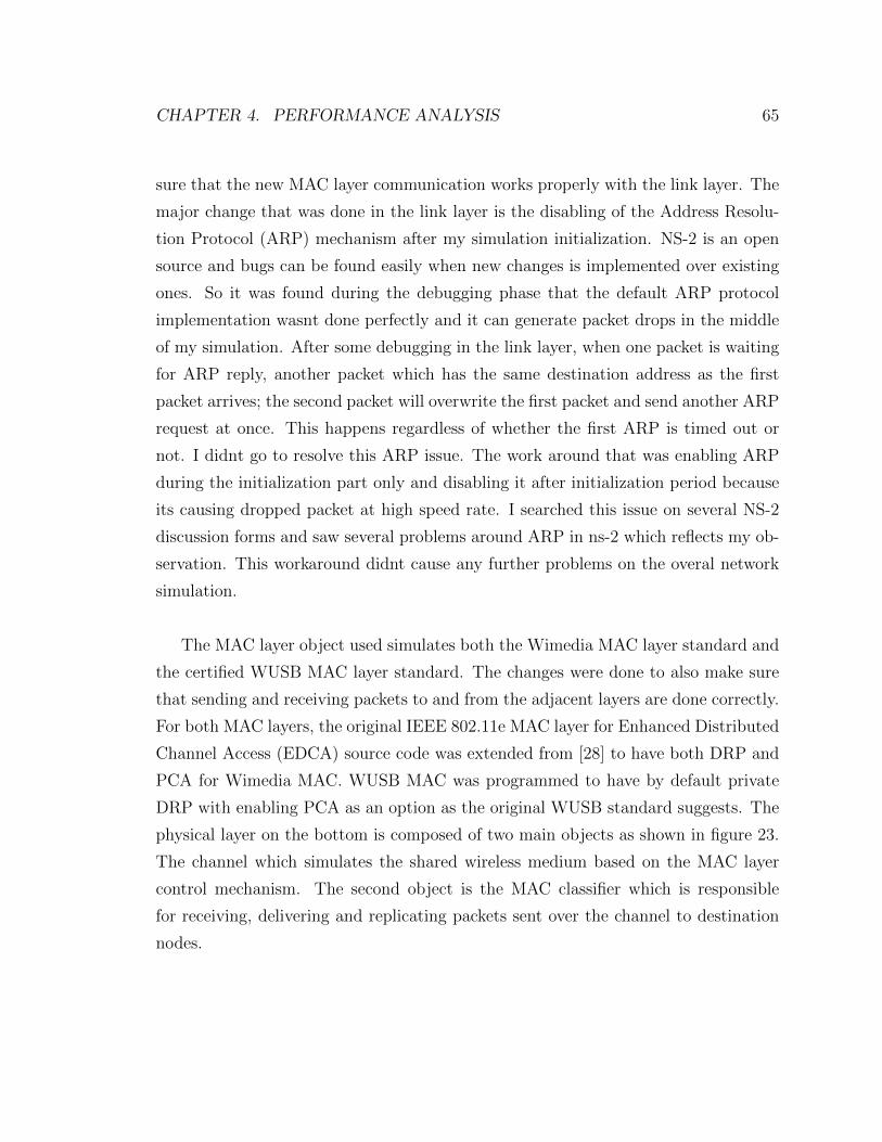
CHAPTER 4. PERFORMANCE ANALYSIS 65
sure that the new MAC layer communication works properly with the link layer. The
major change that was done in the link layer is the disabling of the Address Resolu-
tion Protocol (ARP) mechanism after my simulation initialization. NS-2 is an open
source and bugs can be found easily when new changes is implemented over existing
ones. So it was found during the debugging phase that the default ARP protocol
implementation wasnt done perfectly and it can generate packet drops in the middle
of my simulation. After some debugging in the link layer, when one packet is waiting
for ARP reply, another packet which has the same destination address as the first
packet arrives; the second packet will overwrite the first packet and send another ARP
request at once. This happens regardless of whether the first ARP is timed out or
not. I didnt go to resolve this ARP issue. The work around that was enabling ARP
during the initialization part only and disabling it after initialization period because
its causing dropped packet at high speed rate. I searched this issue on several NS-2
discussion forms and saw several problems around ARP in ns-2 which reflects my ob-
servation. This workaround didnt cause any further problems on the overal network
simulation.
The MAC layer object used simulates both the Wimedia MAC layer standard and
the certified WUSB MAC layer standard. The changes were done to also make sure
that sending and receiving packets to and from the adjacent layers are done correctly.
For both MAC layers, the original IEEE 802.11e MAC layer for Enhanced Distributed
Channel Access (EDCA) source code was extended from [28] to have both DRP and
PCA for Wimedia MAC. WUSB MAC was programmed to have by default private
DRP with enabling PCA as an option as the original WUSB standard suggests. The
physical layer on the bottom is composed of two main objects as shown in figure 23.
The channel which simulates the shared wireless medium based on the MAC layer
control mechanism. The second object is the MAC classifier which is responsible
for receiving, delivering and replicating packets sent over the channel to destination
nodes.

CHAPTER 4. PERFORMANCE ANALYSIS 66
4.2 Simulation Process
The process of the simulator program created goes into several blocks until we get
the results as shown in figure 24. NS-2 will first run each scenario by first creating
a new cluster topology based on the octl scripts run at the NS-2 command prompt.
Each script will call different modules during predefined simulation time to generate
real time results. The NS-2 program is composed of the network modules and event
scheduler. The network modules includes all existing NS-2 modules with the new
generated MAC layer modules created for WUSB and Wimedia. The event schedule
is used to keep track of all time triggering events in a main event queue. The result
of the simulation scenarios generates a real time trace text files containing detail
simulation results. The trace files are processed using AWK program to calculate
results such as throughput, delay and packet loss percentage for each scenario run.
The final step after analyzing the trace file is to display the results in graphical
representation. Matlab was used to generate figure to represent generated results.
Script Scenarios(.tcl)
NS-2 SimulatorOutput
Trace Files(.tr)
NetworkAnalysisProgram(AWK)
Plotting Results(Matlab)
Figure 24: Simulation Proccess Steps
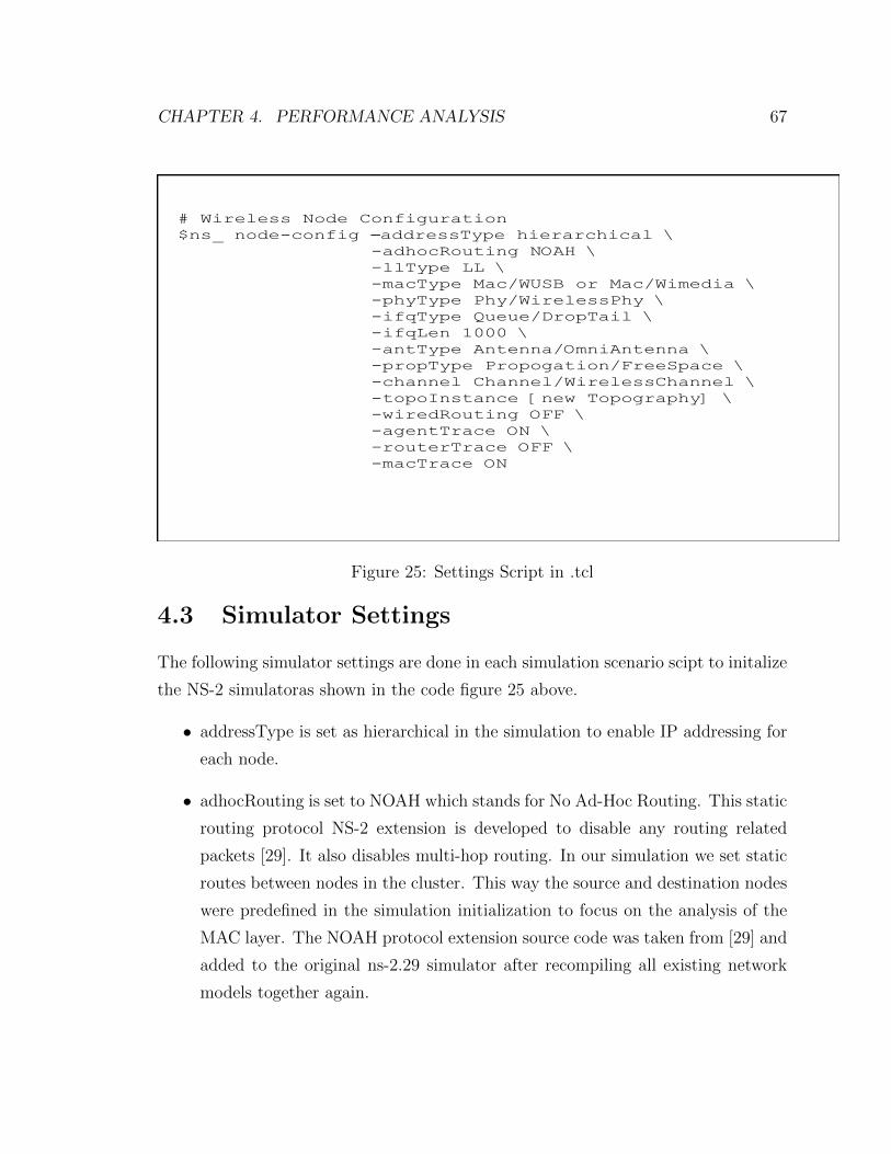
CHAPTER 4. PERFORMANCE ANALYSIS 67
# Wireless Node Configuration
$ns_ node-config –addressType hierarchical \
-adhocRouting NOAH \
-llType LL \
-macType Mac/WUSB or Mac/Wimedia \
-phyType Phy/WirelessPhy \
-ifqType Queue/DropTail \
-ifqLen 1000 \
-antType Antenna/OmniAntenna \
-propType Propogation/FreeSpace \
-channel Channel/WirelessChannel \
-topoInstance [new Topography] \
-wiredRouting OFF \
-agentTrace ON \
-routerTrace OFF \
-macTrace ON
Figure 25: Settings Script in .tcl
4.3 Simulator Settings
The following simulator settings are done in each simulation scenario scipt to initalize
the NS-2 simulatoras shown in the code figure 25 above.
• addressType is set as hierarchical in the simulation to enable IP addressing for
each node.
• adhocRouting is set to NOAH which stands for No Ad-Hoc Routing. This static
routing protocol NS-2 extension is developed to disable any routing related
packets [29]. It also disables multi-hop routing. In our simulation we set static
routes between nodes in the cluster. This way the source and destination nodes
were predefined in the simulation initialization to focus on the analysis of the
MAC layer. The NOAH protocol extension source code was taken from [29] and
added to the original ns-2.29 simulator after recompiling all existing network
models together again.

CHAPTER 4. PERFORMANCE ANALYSIS 68
• llType set to LL representing default link layer.
• macType its either set to the implemented Certified WUSB MAC layer or Wi-
media Layer. Either WUSB or Wimedia.
• phyType is set to the wireless physical layer medium.
• ifqType its set to DropTail which is a simple first in, first out queue.
• ifqLen which is the length of each receiving/sending buffer. Its set to 1000 to
assume we have enough memory in each node.
• antType is set by default to Omni-directional antenna having unity gain for all
mobile nodes.
• propType is set to FreeSpace. FreeSpace type assumes ideal propagation con-
ditions and there is clear line of sight between the two nodes. The maximum
range set is 10 meters so if a receiver is within a circle of 10 meters, it receives
the packets. If its outside the 10 meters range, it starts loosing packets.
• channel is set to WirelessChannel to support the medium access mechanisms of
MAC objects on the sending side of the transmission.
• topoInstance is used by default to provide a node with a handle and link it to
the created topography network object.
• wiredRouting is set to OFF since we are not using a base station.
• agentTrace is set to ON to enable tracing at agent level which helps in debug-
ging.
• routerTrace is set to OFF since we are using NOAH static routing without the
need to have routing messages sent for static node scenarios.
• macTrace is set to ON to enable tracing at the MAC level for generate trace
results.

CHAPTER 4. PERFORMANCE ANALYSIS 69
4.4 Simulation Assumptions
The following assumption were made in the simulations
• The effect of channel errors is ignored in the simulations. In addition UWB
prorogation and fading channel parameters were not included since they are
not currently available for OFDM WUSB. The time to research and generate
such parameters will take considerable time and can be considered in a separate
project. We are currently using only Free Space channel prorogation model in
our simulation.
• No nodes are operating in power save mode. All nodes assumed to have enough
power to remain active throughout the simulation period.
4.5 Optimal Performance Analysis
To reflect the performance of the Certified WUSB, we had to implement the Wimedia
MAC Layer and compare both standard performances for two main reasons:
• Certified WUSB MAC layer takes most its functionality from Wimedia MAC
layer in terms of reusing the same super frame structure and defining its own
private DRP method based on the Wimedia hard DRP type. In addition, it
uses the exact same PCA methodology in Wimedia as an option that can be
enabled.
• As shown in the related work section in this chapter, there not enough study
on Certified WUSB by itself but there are many researches and work that has
been done analyzing the Wimedia MAC layer standard which can be compared
with.
In order to verify the performance of the Wimedia and WUSB MAC layer, theo-
retical analysis has been done first to make sure the outcome of the NS-2 simulation
agrees with the theoretical numbers. Since the PCA MAC layer is derived from the
EDCA rules of 802.11e which are already been reused from the implemented NS-2

CHAPTER 4. PERFORMANCE ANALYSIS 70
module [28]. The only difference that we changed PCA MAC layer to have four Pri-
ority Classes of Audio, Video, Best Efforts and Background whereas EDCA 802.11e
uses seven.Therefore, theoretical analysis was done at the optimal performance and
during DRP reservation phase only by computing results at Wimedia hard DRP and
comparing it to what was achieved by the Private DRP in WUSB. Table 9 shows a
summary of the common parameters between data packets. In addition, the beacon
period of minimum of 4 MAS period will include a ”SIFS + Guard” Time at the end
of the beacon packet. Note: D is the time between the start of the MMC and the
start time of the current packet that must be received as defined in WUSB standard
for calculating Guard Time parameters [9].
Parameter Type ValueSIFS 10µsMIFS 1.875µsStandard Preamble (Std Prem) 9.375µsBurst Preamble (Burst Prem) 5.625µsWimedia Guard Time (Wimedia GT) 12µsWUSB Guard Time (WUSB GT) 1µs where D ≤ 25ms
2µs where 25ms ≤ D ≤ 50ms3µs where D ≥ 50ms
Transaction Turn Time (Trans TT) SIFS + Guard TimePacket Header (Pkt Hdr) 3.75 µsMAS 256µsMinimum Beacon Period 4µsSuper Frame Period 256 MASMaximum Wimedia Packet Size 4095 BytesMaximum WUSB Packet Size 3584 Bytes
Table 9: Common Standard Parameters for WUSB and Wimedia MAC.
4.5.1 Wimedia Theoretical Analysis
To achieve the optimal saturated performance in Wimedia MAC layer without taking
into consideration any channel impairments, we calculated the throughput achieved

CHAPTER 4. PERFORMANCE ANALYSIS 71
between two nodes at close distance between each other. We assumed that a con-
nection is already established between the two devices and beacons were exchanged.
First, the analysis will be done on the case where there is an acknowledgement for
each data packet sent. The source node or host will start sending data at different
rate to the device with having only an immediate acknowledgment sent back to the
source node for each received packet. In addition, figure 26 shows the channel com-
ponents and delays between two nodes in a super frame packet that will be used in
the calculation to find the actual throughput Ta as per equation (8)
ThroughputPercentage =Ta
PhySpeed(8)
Where Ta is the actual received throughput and PhySpeed is the channel speed.
The Actual time it takes to transmit each data payload (Data Transmit) of packet
depends on the size of the packet (Pkt Size) and the physical speed of the channel as
calculated in the following equation
Data Transmit =Pkt Size
PhySpeed(9)
Based on the components described for one transaction, the time it takes for a
transmission is the same in both direction based on figure 26. The transaction period
can be calculated from table 9 and depending on the data packet size, ACK packet
size and channel speed as following:
TransactionPeriodOutgoing(Incoming) = Strd Prem+ Pkt Hdr +Data Transmit
+ SIFS +Wimedia GT + Strd Prem
+ Pkt Hdr + ACK Transmit
+ SIFS +Wimedia GT
(10)
After that the number of transaction period (Num Trans) in a super frame can
be calculated as following:
Num Trans =MAS
TransactionPeriodOutgoing(Incoming)∗ 255 (11)

CHAPTER 4. PERFORMANCE ANALYSIS 72
The actual throughput can be found by calculating how much percentage the ac-
tual data transaction takes from the super frame.
Ta =Phy Speed ∗Num Trans ∗Data Transmit
256∗MAS (12)
Beac
onPe
riod
Time
= Host Transmission
= Device Transmission
Super Frame 65536 us
Stan
dard
Pr
eam
ble
Pack
et
Hea
der Data 0
Payload Gua
rdTi
me
Stan
dard
Pr
eam
ble
Pack
et
Hea
der
ACK 0Payload
= Inter Packet Delays
Gua
rdTi
me
SIFS
SIFS
Beac
onPe
riod
(a) Host Outgoing Data Stream
One Data Transaction
TimeSuper Frame 65536 us
Beac
onPe
riod
Stan
dard
Pr
eam
ble
Pack
et
Hea
der Data 0
Payload
SIFS
Gua
rdTi
me
Stan
dard
Pr
eam
ble
Pack
et
Hea
der
ACK 0Payload
SIFS
Gua
rdTi
me
Beac
onPe
riod
One Data Transaction
(b) Device Incoming Data Stream
Figure 26: (a)Wimedia Immediate ACK Outgoing Data Transfer. (b)Wimedia Im-mediate ACK Incoming Data Transfer.
Second analysis will be done on the case where there is a burst acknowledgement
for a data burst size of 16 data packets which represent the maximum case. The
source node or host will start sending data at different rate to the device with having
only one burst acknowledgment sent back to the source node after the last received
packet in one transaction. In addition, figure 27 shows the channel components and
delays between two nodes in a super frame packet. Based on the components de-
scribed for one transaction, the time it takes for a transmission is the same in both
direction based on figure 26 for Wimedia burst data phase. The transaction period

CHAPTER 4. PERFORMANCE ANALYSIS 73
can be calculated from table 9 and depending on the data packet size, ACK packet
size and channel speed as following:
TransactionPeriodOutgoing(Incoming) = Strd Prem+ Pkt Hdr +Data Transmit
+ 15 ∗ (MIFS +Wimedia GT +Burst Prem
+ Pkt Hdr +Data Transmit)
+ SIFS +Wimedia GT + Strd Prem+ Pkt Hdr
+BurstACK Transmit
+ SIFS +Wimedia GT
(13)
Note that the burst preamble is used only for bit rates higher than 200 Mbps.
For any lower bit rate, the standard preamble is used. Finally, the transaction period
can be plugged in equation (11) to find the total number of transaction periods to be
used in calculating the actual throughput in equation (12).
The theoretical values for both immediate ACK and burst ACK cases are shown
in figure 28 for all supported bit speeds and fixing the packet size to the maximum
value of 4095 bytes. The burst size of 16 is used to simulate the optimal performance
case theoretically. It can be noticed from the plot that the packet delivery ratio
is a lot higher for the burst ACK case which improves throughput of the network
considerably. The reason is that when using the burst case, the delay between data
packets sent is smaller and set to MIFS instead of SIFS for the immediate ACK case.
In addition, we are sending one ACK packet back for each 16 successfully received.
Moreover, it can be from noticed that as the data rate used is increased, the actual
throughput received is lower. For example, when the speed rate is set to 480 Mbps,
the actual throughput received is around 336 Mbps which is 70% of the original speed
as shown in the figure. In figure 29, theoretical results were plot for both cases again
but this time with fixing the data speed rate to 480 Mbps and changing the packet
size to all supported packet sizes for Wimedia. It shows from the plot that as the
packet size used is increased, the higher the packet delivery ratio and the higher actual

CHAPTER 4. PERFORMANCE ANALYSIS 74
Beac
onPe
riod
Time
= Host Transmission
= Device Transmission
Super Frame 65536 us
Burs
t Pr
eam
ble
Pack
et
Hea
der
Dat
a 15
Payl
oad
Gua
rdTi
me
Stan
dard
Pr
eam
ble
Pack
et
Hea
der
Burs
t ACK
Pa
yloa
d
= Inter Packet Delays
Gua
rdTi
me
SIFS
SIFS
(a) Host Outgoing Data Stream
One Data Transaction
TimeSuper Frame 65536 us
Beac
onPe
riod
Stan
dard
Pr
eam
ble
Pack
et
Hea
der
MIF
S
SIFS
Gua
rdTi
me
One Data Transaction
(b) Device Incoming Data Stream
Stan
dard
Pr
eam
ble
Pack
et
Hea
der
Dat
a 0
Payl
oad
MIF
S
Burs
t ACK
Pa
yloa
d
Pack
et
Hea
der
Stan
dard
Pr
eam
ble
Gua
rdTi
me
Dat
a 0
Payl
oad
Burs
t Pr
eam
ble
Pack
et
Hea
der
Dat
a 15
Payl
oad SIFS
Gua
rdTi
me
Gua
rdTi
me
Figure 27: (a)Wimedia Burst ACK Outgoing Data Transfer. (b)Wimedia Burst ACKIncoming Data Transfer.
throughput received. This shows the effect of the packet header size ratio to the actual
data payload. Therefore, its recommended to send data at the maximum packet size
rate to achieve the highest throughput assuming a channel without errors in this case.

CHAPTER 4. PERFORMANCE ANALYSIS 75
Figure 28: Theortical Wimedia Packet Delivery Ratio with All Supported Bit Rates
Figure 29: Theortical Wimedia Packet Delivery Ratio with All Supported PacketSizes at 480Mbps
4.5.2 WUSB Theoretical Analysis
To achieve the optimal saturated performance in WUSB MAC layer without taking
into consideration any channel impairments, the throughput was calculated between
two nodes at close distance between each other. For example, 1 meter apart. We
assumed that a connection is already established between the two devices and bea-
cons were exchanged. First, the analysis will be done on the case where there is
an acknowledgement for each data packet sent. The source node or host will start

CHAPTER 4. PERFORMANCE ANALYSIS 76
sending data at different rate to the device with having only an immediate acknowl-
edgment sent back to the source node for each received packet. In addition, figure 30
shows the channel components and delays between two nodes in a super frame packet.
Beac
onPe
riod
Time
SIFS
= Host Transmission
= Device Transmission
Super Frame 65536 us
Stan
dard
Pr
eam
ble
Pack
et
Hea
der Data 0
Payload Gua
rdTi
me
Stan
dard
Pr
eam
ble
Pack
et
Hea
der
ACK 0Payload
= Inter Packet Delays
Gua
rdTi
me
SIFS
SIFS
Beac
onPe
riod
(a) Host Outgoing Data Stream
One Data Transaction
TimeSuper Frame 65536 us
Beac
onPe
riod
Gua
rdTi
me
Stan
dard
Pr
eam
ble
Pack
et
Hea
der Data 0
Payload
SIFS
Gua
rdTi
me
SIFS
Beac
onPe
riod
One Data Transaction
(b) Device Incoming Data Stream
MM
C
MM
C
MM
C
MM
C
Figure 30: (a)WUSB Immediate ACK Outgoing Data Transfer. (b)WUSB ImmediateACK Incoming Data Transfer.
Based on the components described for one transaction, the time it takes for a
transmission is different in both directions based on figure 30. The reason is that the
acknowledgement for a data packet received from a device is done through the next
MMC packet. The MMC packet is calculated based on the smallest data rate of 53.3
Mbps.

CHAPTER 4. PERFORMANCE ANALYSIS 77
MMC Pkt = Strd Prem+ Pkt Hdr +MMC Payload
= 9.375µs+ 3.75µs+ 3µs
= 16.125µs
(14)
The transaction period can be calculated from table 9 and depending on the data
packet size, ACK packet size and channel speed as following:
TransactionPeriodOutgoing = MMC Pkt+ SIFS + Strd Prem+ Pkt Hdr +Data Transmit
+ SIFS +WUSB GT + Strd Prem
+ Pkt Hdr + ACK Transmit
+ SIFS +WUSB GT
(15)
TransactionPeriodIncoming = MMC Pkt+ SIFS +WUSB GT
+ Strd Prem+ Pkt Hdr +Data Transmit
+ SIFS +WUSB GT
(16)
Finally, the transaction period can be plugged in equation (11) to find the total
number of transaction period and then calculating the actual throughput in a similar
way to the Wimedia part in equation (12).
Second analysis will be done on the case where there is a burst acknowledgement
for a data burst size of 16 data packets which represent the maximum case. The
source node or host will start sending data at different rate to the device with having
only one burst acknowledgment sent back to the source node after the last received
packet in one transaction. In addition, figure 31 shows the channel components and
delays between two nodes in a super frame packet.
Based on the components described for one transaction, the time it takes for a
transmission is different in both directions based on figure 31 The reason is that the
burst acknowledgement for a data packet sent from a device is done through the next
MMC packet sent. The MMC packet is calculated as in equation (14) based on the

CHAPTER 4. PERFORMANCE ANALYSIS 78
Beac
onPe
riod
Time
= Host Transmission
= Device Transmission
Burs
t Pr
eam
ble
Pack
et
Hea
der
Dat
a 15
Payl
oad
Gua
rdTi
me
Stan
dard
Pr
eam
ble
Pack
et
Hea
der
Burs
t ACK
Pa
yloa
d
= Inter Packet Delays
Gua
rdTi
me
SIFS
SIFS
(a) Host Outgoing Data Stream
One Data Transaction
Time
Beac
onPe
riod
Stan
dard
Pr
eam
ble
Pack
et
Hea
der
MIF
S
SIFS
Gua
rdTi
me
One Data Transaction
(b) Device Incoming Data Stream
Stan
dard
Pr
eam
ble
Pack
et
Hea
der
Dat
a 0
Payl
oad
MIF
SD
ata
0Pa
yloa
d
Burs
t Pr
eam
ble
Pack
et
Hea
der
Dat
a 15
Payl
oad
MM
C Pa
cket M
IFS
MM
C Pa
cket
MM
C Pa
cket
MM
C Pa
cket
Gua
rdTi
me
SIFS
Figure 31: (a)WUSB Burst ACK Outgoing Data Transfer. (b)WUSB Burst ACKIncoming Data Transfer.
smallest data rate of 53.3 Mbps. The transaction period can be calculated from table
9 and depending on the data packet size, ACK packet size and channel speed as
following:
TransactionPeriodOutgoing = MMC Pkt+MIFS + Strd Prem+ Pkt Hdr
+Data Transmit
+ 15 ∗ (MIFS +Burst Prem+ Pkt Hdr +Data Transmit)
+ SIFS +WUSB GT + Strd Prem
+ Pkt Hdr +BurstACK Transmit
+ SIFS +WUSB GT
(17)

CHAPTER 4. PERFORMANCE ANALYSIS 79
TransactionPeriodIncoming = MMC Pkt+ SIFS +WUSB GT
+ Strd Prem+ Pkt Hdr +Data Transmit
+ 15 ∗ (MIFS +Burst Prem+ Pkt Hdr +Data Transmit)
+ SIFS +WUSB GT
(18)
Finally, the transaction period can be plugged in equation (11) to find the total
number of transaction periods and then calculating the actual throughput in a similar
way to the Wimedia part in equation (12).
The theoretical values for both immediate ACK and burst ACK cases for WUSB
were plot in figure 32 for all supported bit speeds and fixing the packet size to the
maximum value of 3584 bytes. The burst size used is 16 to simulate the optimal
performance cases theoretically. It can be noticed from the plot that the packet
delivery ratio is a lot higher for the burst ACK case which improves throughput
of the network considerably. The reason is that when using the burst case, the
delay between data packet sent is smaller and set to MIFS instead of SIFS for the
immediate ACK case. In addition, we are sending one ACK packet back for each 16
successfully received. Outgoing data packets can have slightly more delays since it
requires an actual acknowledgement sent back from the destination device. On the
other hand, incoming data packets as shown in figure 32 require less delays since the
acknowledgement can be put in the next MMC sent. Moreover, it can be from noticed
that as the data rate used is increased, the actual throughput received is lower. For
example, when the speed rate is set to 480 Mbps, the actual throughput received is
around 384 Mbps which is 80% of the original speed as shown in the figure. In figure
33, theoretical results were plot for both cases again but this time with fixing the
data speed rate to 480 Mbps and changing the packet size to all the support packet
sizes for WUSB. It shows from the plot that as the packet size used is increased,
the higher the packet delivery ratio and the higher actual throughput received. This
shows the effect of the packet header size ratio to the actual data payload. Therefore,
its recommended to send data at the maximum packet size rate to achieve the highest
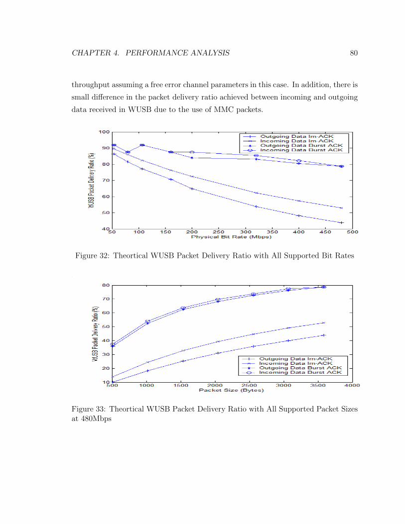
CHAPTER 4. PERFORMANCE ANALYSIS 80
throughput assuming a free error channel parameters in this case. In addition, there is
small difference in the packet delivery ratio achieved between incoming and outgoing
data received in WUSB due to the use of MMC packets.
Figure 32: Theortical WUSB Packet Delivery Ratio with All Supported Bit Rates
Figure 33: Theortical WUSB Packet Delivery Ratio with All Supported Packet Sizesat 480Mbps

CHAPTER 4. PERFORMANCE ANALYSIS 81
4.5.3 Simulation Analysis under Perfect Conditions
The simulated MAC layer for both Wimedia and WUSB was programmed in NS-2 and
verified by comparing the output results from the simulation to the optimal theoretical
results as show in figure 34. The curves in blue color represent the theoretical results
and the curves in red represent the simulated results. The figure shows the packet
delivery ratio as the bit rate increases for both Wimedia and WUSB. It shows that
there is a small difference between the theoretical and simulated values which is
reasonable. These simulated results represent an average of the running output of
five simulations to find an accurate representations. The simulation scenario used is
the same as the ones used in the theoretical calculation where only one source node
is sending to a one meter far destination at full capacity without having DNTS slots
to simulate the saturated case. The second figure shows the packet delivery ratio
again but by fixing the bit rate to 480 Mbps and varying the packet size. Figure 35
shows that simulated and theoretical curves are very close to each other which helps
in verifying the protocol side of the programmed MAC layer for both standards.
Figure 34: Simulation Comparing Wimedia and WUSB Packet Delivery Ratio withAll Supported Bit Rates
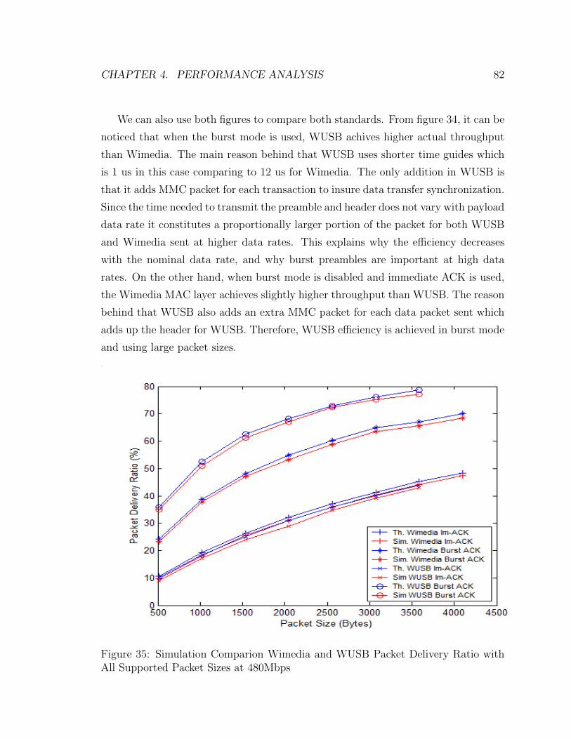
CHAPTER 4. PERFORMANCE ANALYSIS 82
We can also use both figures to compare both standards. From figure 34, it can be
noticed that when the burst mode is used, WUSB achives higher actual throughput
than Wimedia. The main reason behind that WUSB uses shorter time guides which
is 1 us in this case comparing to 12 us for Wimedia. The only addition in WUSB is
that it adds MMC packet for each transaction to insure data transfer synchronization.
Since the time needed to transmit the preamble and header does not vary with payload
data rate it constitutes a proportionally larger portion of the packet for both WUSB
and Wimedia sent at higher data rates. This explains why the efficiency decreases
with the nominal data rate, and why burst preambles are important at high data
rates. On the other hand, when burst mode is disabled and immediate ACK is used,
the Wimedia MAC layer achieves slightly higher throughput than WUSB. The reason
behind that WUSB also adds an extra MMC packet for each data packet sent which
adds up the header for WUSB. Therefore, WUSB efficiency is achieved in burst mode
and using large packet sizes.
Figure 35: Simulation Comparion Wimedia and WUSB Packet Delivery Ratio withAll Supported Packet Sizes at 480Mbps

CHAPTER 4. PERFORMANCE ANALYSIS 83
4.5.4 Simulation Analysis under Connection Failures
The simulated MAC layers were also verified against packet loss parameters. In order
to achieve that without using experimental channel impairment, an average random
packet loss routine was added in the physical layer side in NS-2. The simulation
scenario used was again between two nodes one meter apart. The source node was
sending to the destination at different bit rates. The DNTS slot was disabled in this
scenario to verify simulations under saturated case. The theatrical results with aver-
age packet loss of 10% were plotted in figure 36 where wireless medium can achieve
such a high average packet loss rate. The simulated results were plotted and it can
be shown in figure 36 that its close to the theoretical value which verifies again the
functionality of both MAC layer simulations. It can be noted that WUSB still achieve
higher actual throughput in burst mode than Wimedia. It achieves lower throughput
when its set to use immediate ACK.
Figure 36: Simulation Comparing Wimedia and WUSB Packet Delivery Ratio withAll Supported Bit Rates under 10% Packet Loss
Chapter 5
Protocol Improvements to
Certified WUSB
5.1 Enabling Priority Option for Delay Sensitive
Applications
5.1.1 Background and Motivation
Wireless video streaming over UWB radio is one of the great advantages that Certified
WUSB can offer. One of the demonstrations that were done was using a Nokia 7710
phone as a UWB transmitter and a projector as a UWB receiver. The throughput
measured near 200Mbps is a proof that UWB can offer great opportunity for short
range wireless video streaming [30]. Certified WUSB has been adopted by several
major players in the field of wireless home networks such as Intel, D-Link, Samsung,
DELL, and Belkin. Two devices have been developed for WUSB. One is HWA which
enables a USB 2.0 device to act like a host device and send MMC control packets.
The other device is called DWA which enables other peripherals to participate in the
WUSB network [9]. Therefore, any USB 2.0 webcam or camera can be connected
wirelessly to a UWB WUSB network through the use of wireless DWA adaptor which
is available in the market. Those WUSB cameras and webcams can be connected to
a PC having an HWA adaptor installed. The webcam or camera can be remotely
84
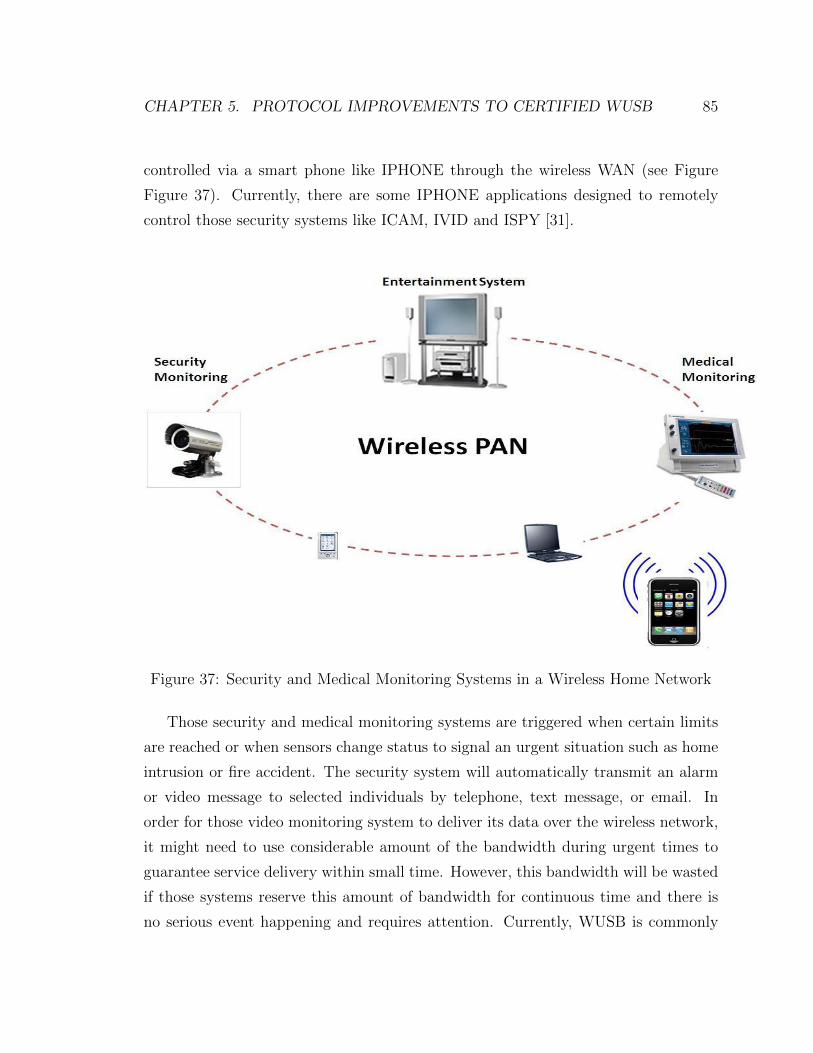
CHAPTER 5. PROTOCOL IMPROVEMENTS TO CERTIFIED WUSB 85
controlled via a smart phone like IPHONE through the wireless WAN (see Figure
Figure 37). Currently, there are some IPHONE applications designed to remotely
control those security systems like ICAM, IVID and ISPY [31].
Figure 37: Security and Medical Monitoring Systems in a Wireless Home Network
Those security and medical monitoring systems are triggered when certain limits
are reached or when sensors change status to signal an urgent situation such as home
intrusion or fire accident. The security system will automatically transmit an alarm
or video message to selected individuals by telephone, text message, or email. In
order for those video monitoring system to deliver its data over the wireless network,
it might need to use considerable amount of the bandwidth during urgent times to
guarantee service delivery within small time. However, this bandwidth will be wasted
if those systems reserve this amount of bandwidth for continuous time and there is
no serious event happening and requires attention. Currently, WUSB is commonly

CHAPTER 5. PROTOCOL IMPROVEMENTS TO CERTIFIED WUSB 86
used to provide high bit rate within the home environment. Its standard specifies
that each node has the ability to reserve half of the current bandwidth for use in pri-
vate DRP which could become a bottleneck to deploy practical multimedia streaming
service [32]. Moreover, some of those video services have more urgency like security
and medical system monitoring which has no support in WUSB standard.
5.1.2 Proposed Model
In WUSB, the reservation node which sends those MMC control message allow in-
terrupts from other node via allocation slot called DNTS. This DNTS window allows
other devices to send connect requests to the host node asynchronously via Slot-
ted ALOHA mechanism. The host which reserves the WUSB channel will randomly
move the locations of the DNTS window over different MAS slots over time to allow
connection opportunities. The new node that has urgent data will try to join the
wireless network by waiting for acknowledgement from the host node to establish a
connection. If the new node fails to receive acknowledgements to join the channel, it
performs retransmissions. The WUSB standard defines a maximum of three retrans-
mission requests for each 100 milliseconds interval. The new node then negotiates
to reserve MAS slots by checking the MAS available information sent via the bea-
cons. Then the new node will ask to reserve MAS slots by replying back to the host
reservation node that established the wireless channel initially. This process can take
considerable time preventing data from being transmitted; obviously a serious limi-
tation. The second weakness is when all MAS slots are already taken and used when
a security webcam detects an emergency situation. In WUSB private DRP, all slots
are hard reserved and only available to the reserved node as in hard DRP and set in
the standard as SAFE MAS slots. Therefore, there is no process to free MAS slots a
for higher priority application. This way, if a security monitor wants to send video
data to the controller PC and the bandwidth is already allocated to the maximum
for existing system, the security monitor will be blocked and it needs to wait until
MAS slots are available.

CHAPTER 5. PROTOCOL IMPROVEMENTS TO CERTIFIED WUSB 87
In order to provide priority option for WUSB to support security and medical
systems that use private DRP, we propose to change the DRP type to soft DRP
instead. The current WUSB standard can be tweaked to support that. We propose
two changes. First change is to enable PCA in WUSB MAC which is currently an
option available in the standard and is disabled by default [9]. The command used
to set the PCA availability option is called Set IE which is set in the beacon config-
uration. Second change is having the unsafe bit in the DRP Control field of a DRP
Information Element configuration of the Wimedia MAC standard set to zero [6]. A
device that has the unsafe bit set may be preempted by other devices to give up the
extra MASs it has reserved. The MAC allows unsafe reservations in soft DRP so that
devices can take advantage of the full capacity of the super frame whenever possible.
The two changes will have PCA and soft DRP enabled in WUSB. Therefore, the
node that provides security or medical monitoring will make the soft DRP reserva-
tion while the rest of the nodes will continue competing for bandwidth according to
PCA rules. This way the reserved node which is the host in this case has no delay
if soft DRP is used and can access the channel before other regular video applications.
5.1.3 Simulation Results
The simulation was done using the extended 802.11e EDCA model implemented NS-2
to model WUSB MAC PCA option by enabling four priority levels instead of seven
[28]. The used simulation parameters taken from the WUSB standard are listed in
Table 10
The traffic model for video and voice applications are usually bursty in nature.
However, due to the fact that NS-2 only has CBR supported and our simulation pur-
pose is around channel access characteristic only, CBR traffic mode is used to simulate
both video and voice stream traffic at a constant rate. The first scenario was done in
a WUSB private DRP network by setting the maximum bandwidth to 100 Mbps and
has three transmission connections between nodes is set at a distance of 3 meters.
The fist transmission will simulate webcam video traffic with a speed of 30 Mbps.

CHAPTER 5. PROTOCOL IMPROVEMENTS TO CERTIFIED WUSB 88
The second transmission will simulate HDTV video traffic with a speed of 50 Mbps.
The first two transmissions will start together at time 0 seconds of the simulation
as shown in Figure 38. In the figure, throughput of each transmission is normalized
to the maximum bandwidth of 100 Mbps. The third transmission represents traffic
coming from a security monitor node with a speed of 50 Mbps which starts to send
at the 5th second of the simulation time line. Since there is no priority handling in
WUSB private DRP, the first two transmissions are allocated bandwidth according
to its initial requirement. Also, both transmissions are using less than half of the
maximum bandwidth which means that the allocated slots are set to SAFE mode in
WUSB and they cant be requested by another node until the end of their transmis-
sion. Therefore, the third transmission has only third of the bandwidth available and
thats why the curve representing third transmission is allowed a bit speed rate of 25-
28 Mbps as shown in Figure 38. The issue with this scenario is when a security alarm
is triggered within a home, it can only reserve portion of the bandwidth available and
the video will be sent at lower quality. In addition, its noticed that there is about
300 to 400 ms delay to establish the third transmission and allocation of the rest of
the MAS slots are done.
Parameter V alueNumber of Connections 3Transmission Range 2 metersTransport Type UDPTraffic Type CBRPacket Size(with headers) 3584 BytesMAS 256 µsSIFS Time 10 µsGuard time 3 µs
Table 10: NS-2 Simulation Parameters
The second scenario would be similar to the first scenario except that first two
transmissions will use all the 100 Mbps bandwidth equally. Then when a third trans-
mission starts later, it will find no available MAS slot which explains why the third
transmission wont start and will be blocked from transmission even though it has a

CHAPTER 5. PROTOCOL IMPROVEMENTS TO CERTIFIED WUSB 89
Figure 38: Throughput Simulation based on WUSB Private DRP MAC
higher priority and urgency over the two transmissions.
The third scenario would be to change the private DRP to have both soft DRP
and PCA enabled. The initial configuration would have the security monitor node
set to be the soft DRP reservation owner without sending any data. Then the band-
width will be available for contention based node part of the PCA type. This way
similar to the first scenario, the first two transmissions will start at time 0 in the
simulation with voice transmission set to 30 Mbps and video transmissions will be set
to 50 Mbps. Both video transmissions will use the second PCA priority parameters
set in table 1. Then after five seconds, the security monitor node will be triggered
and starts to send data at a speed of 50 Mbps. In soft DRP reservation, the AIFS
time is set to zero and no back-off timer is initialized before the third transmissions.
This way it will minimize any delays. This way third transmission will use all the 50
Mbps speed right away since it will start transmission without delays and before any
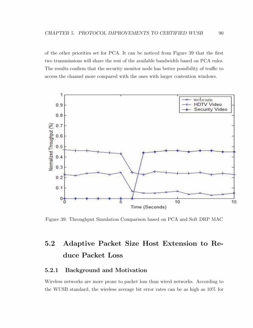
CHAPTER 5. PROTOCOL IMPROVEMENTS TO CERTIFIED WUSB 90
of the other priorities set for PCA. It can be noticed from Figure 39 that the first
two transmissions will share the rest of the available bandwidth based on PCA rules.
The results confirm that the security monitor node has better possibility of traffic to
access the channel more compared with the ones with larger contention windows.
Figure 39: Throughput Simulation Comparison based on PCA and Soft DRP MAC
5.2 Adaptive Packet Size Host Extension to Re-
duce Packet Loss
5.2.1 Background and Motivation
Wireless networks are more prone to packet loss than wired networks. According to
the WUSB standard, the wireless average bit error rates can be as high as 10% for

CHAPTER 5. PROTOCOL IMPROVEMENTS TO CERTIFIED WUSB 91
1000 bytes packets [9]. This significant average of packet loss can have big affect on
the QoS that voice and video multimedia applications wants to offer through the wire-
less medium. One of the common ways to decrease the packet loss rate is through
retransmissions. The UWSB standard specifies that retransmissions can occur no
more than three times for every 100 ms of data transfer. In addition, the rate of
retransmission can be controlled through the host device. However, retransmission in
the wireless medium can cause more delays and can reduce the overall throughput of
the network. An acceptable one way voice signal delay is less than 150ms according
to ITU-T G.114 [33] and packet loss should be kept below 10% according to ITU-T
P.862 [34]. In addition, acceptable one way video delay according to ITU-T H.261 is
less than 400ms and acceptable packet loss is less than 10% [35].
One important aspect found when analyzing WUSB MAC layer performance while
varying packet size that the packet loss rate decrease when using small packet sizes.
Figure 40 shows the packet loss rate at all supported packet sizes. The simulation
was done with two nodes at speed rate of 100 Mbps. In addition, simulations were
run five times to get accurate approximate of the total packet loss in this scenario. It
can be noticed that using smaller packet sizes achieves the lowest total packet loss,
the reason is that when smaller packets is lost, the retransmission is done on less data
than when using larger packet sizes. This way more data is received at the destination
node and the lost packet is percentage is lower.
Another paper found in literature suggest the need for an intelligent streaming
application to analyze the delay pattern for packet with different length which can
be useful in adjusting application level framing under different network condition to
optimize the wireless network utilization [36]. Therefore, a mechanism is needed to
adjust the packet rate used to reduce overall network packet loss percentage.

CHAPTER 5. PROTOCOL IMPROVEMENTS TO CERTIFIED WUSB 92
Figure 40: Total Average Packet Loss Simulation Comparison with All SupportedPacket Sizes
5.2.2 Proposed Model
Our proposed model is to have the bit speed rate set at the required data rate for
an application without reducing that speed and adaptively changing the packet size
sent into the channel. There are two reasons behind fixing the data rate at the re-
quested speed rate. One is that when sending at the highest requested data rate,
multimedia application can achieve the highest possible throughput for its service to
be sent without delays effecting QoS and help in achieving the highest utilization of
the network bandwidth. Another reason found through research on wireless LANs
that transmitting at the highest possible data rate can minimize the energy per bit
consumed which means can help increase the life time of the device or host in the
cluster [37].

CHAPTER 5. PROTOCOL IMPROVEMENTS TO CERTIFIED WUSB 93
Therefore, our proposed model is based on having the host change the supported
packet size during the data transfer. The host has advantage of changing bit rate
and packet size support during the channel life through beacons. This advantage can
be used to adopt an adaptive method to change the used packet size depending on
the measured packet loss. The host functionality can be extended either at the MAC
layer or at the application layer to program adaptive packet size change routine. In
our simulation, we added this routine at the WUSB MAC layer in NS-2 as an extra
module. An example of the functionality can be simplified in diagram 41. A host can
start sending data at the requested bit rate speed and starting at maximum packet
size for example at 3584 bytes supported in order to achieve the highest throughput.
Then during the data transfer, the host will keep track of the number of packets
were lost over the last period of 10 superframes to calculate the average packet loss
percentage. The interval of 10 super frames was chosen by trial and error. Once the
percentage of the average packet loss becomes at 10%, the host will reduce the current
packet by a 512 byte interval to a new packet size of 3072 bytes. The host will then
send back notification in the next beacon period in its IE part that the new packet
size is 3072 bytes and using the same reservation MAS slots periods. The host will
recalculate the average packet loss achieved for that particular data transfer and if
the packet loss doesnt go below the 10% value before the next beacon period, another
packet size reduction will be done. This process will continue until the lowest possible
packet size of 512 bytes. As shown in diagram 41, if the host notices that average
packet loss rate is lower than 10%, then it will start increasing the packet size until it
reaches the original one. This way if packet loss is reduced, it can still try and achieve
the highest network throughput by increase the packet size back to its original setting.
5.2.3 Simulation Results
The WUSB MAC layer was extended to add a routine to calculate the packet loss
rate at the host side only. This addition required to keep track of static variable of
the current packet loss rate value which is calculated by dividing the number of bytes

CHAPTER 5. PROTOCOL IMPROVEMENTS TO CERTIFIED WUSB 94
Figure 41: Diagram of the Proposed Adaptive Packet Change Mechanism at HostSide.
was lost in the last 10 super frames with the total number of bytes received in the
last 10 super frames. The scenario used in the simulation is between two nodes with
one transfer between a host and device with speed rate of 100 Mbps and using the
maximum packet size of 3584 bytes. The limitation of the packet loss was set to 10%.
The channel impairment assumed to be negligible in this case. The simulation was
run for 100 seconds five times to find the average packet size. This figure 42 shows
two curves, one without the adaptive packet size method and one with. It shows that
maximum packet size achieved during the simulation for the host adaptive packet size
mechanism try to always stay at 10% packet loss mark which helps in meeting the
QoS criteria set for both video and voice in the ITU standards without reducing the
actual bit rate speed.
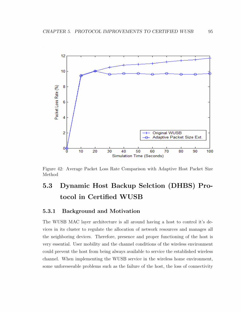
CHAPTER 5. PROTOCOL IMPROVEMENTS TO CERTIFIED WUSB 95
Figure 42: Average Packet Loss Rate Comparison with Adaptive Host Packet SizeMethod
5.3 Dynamic Host Backup Selction (DHBS) Pro-
tocol in Certified WUSB
5.3.1 Background and Motivation
The WUSB MAC layer architecture is all around having a host to control it’s de-
vices in its cluster to regulate the allocation of network resources and manages all
the neighboring devices. Therefore, presence and proper functioning of the host is
very essential. User mobility and the channel conditions of the wireless environment
could prevent the host from being always available to service the established wireless
channel. When implementing the WUSB service in the wireless home environment,
some unforeseeable problems such as the failure of the host, the loss of connectivity
CHAPTER 5. PROTOCOL IMPROVEMENTS TO CERTIFIED WUSB 96
between the host and other devices because of the network topology change or mobil-
ity will bring the WUSB cluster network to a complete halt [38],[39]. A backup plan
is needed to prevent that from happening.
5.3.2 Proposed Model
One possible procedure to introduce redundancy in a WUSB cluster is to have a
backup host to maintain the process of the cluster communication in case of the orig-
inal host failure. Since the existing WUSB standard doesnt provide the criteria of
selecting such a backup host and the procedure of how to reorganize the network [9],
we propose a method called Dynamic Host Backup Selection (DHBS). This method
relies on the availability of self beconing devices around the host which have the full
implementation of the WUSB MAC layer and can perform beaconing.
The original host can create a list of neighbors of only self beaconing devices.
This host can find if the device is a self beacon device from the connection notifi-
cation message attributes if its set to 10 bit value as per the UWSB standard. The
backup host selection will depend on a new algorithm we suggest. After research in
the WUSB standard, we came up with the following parameters that are important
to select the best candidate to be the backup host. Those criteria are listed in table
5.3.2 and are part of a backup weighting function. The first parameter is that the
backup host should have enough energy to support the existing channel. The second
parameter is that the self beacon device with the highest number of matching neigh-
bors as the original host neighbors should have an advantage. The third parameter
is CPU indicator which indicates the processing capability of the device.
The backup weighting function can be calculated as following:
Backup Weight = Power Level +Number Neigbhors+ CPU Indicator (19)
The original host will choose the self beacon device with the highest weighting
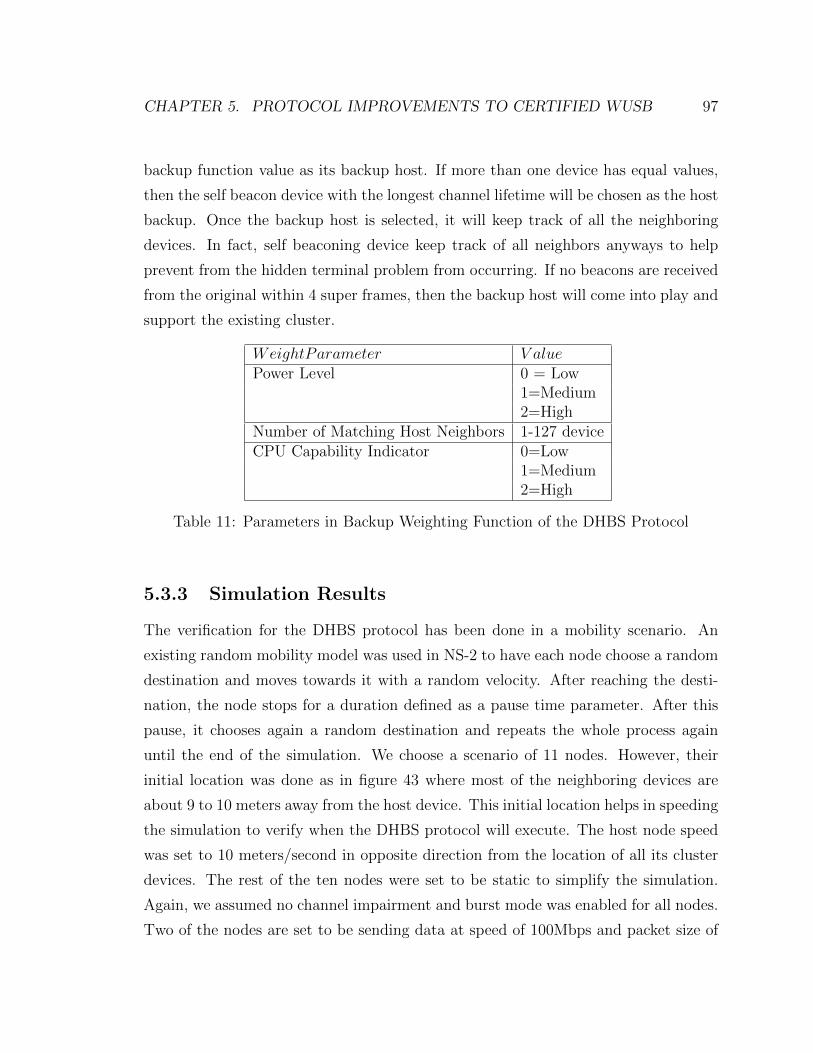
CHAPTER 5. PROTOCOL IMPROVEMENTS TO CERTIFIED WUSB 97
backup function value as its backup host. If more than one device has equal values,
then the self beacon device with the longest channel lifetime will be chosen as the host
backup. Once the backup host is selected, it will keep track of all the neighboring
devices. In fact, self beaconing device keep track of all neighbors anyways to help
prevent from the hidden terminal problem from occurring. If no beacons are received
from the original within 4 super frames, then the backup host will come into play and
support the existing cluster.
WeightParameter V aluePower Level 0 = Low
1=Medium2=High
Number of Matching Host Neighbors 1-127 deviceCPU Capability Indicator 0=Low
1=Medium2=High
Table 11: Parameters in Backup Weighting Function of the DHBS Protocol
5.3.3 Simulation Results
The verification for the DHBS protocol has been done in a mobility scenario. An
existing random mobility model was used in NS-2 to have each node choose a random
destination and moves towards it with a random velocity. After reaching the desti-
nation, the node stops for a duration defined as a pause time parameter. After this
pause, it chooses again a random destination and repeats the whole process again
until the end of the simulation. We choose a scenario of 11 nodes. However, their
initial location was done as in figure 43 where most of the neighboring devices are
about 9 to 10 meters away from the host device. This initial location helps in speeding
the simulation to verify when the DHBS protocol will execute. The host node speed
was set to 10 meters/second in opposite direction from the location of all its cluster
devices. The rest of the ten nodes were set to be static to simplify the simulation.
Again, we assumed no channel impairment and burst mode was enabled for all nodes.
Two of the nodes are set to be sending data at speed of 100Mbps and packet size of

CHAPTER 5. PROTOCOL IMPROVEMENTS TO CERTIFIED WUSB 98
3584 bytes. One data transfer is from node 7 to node 9. The other data transfer is
from node 4 to 5. Looking at figure 43 and assuming all nodes have medium level
power, the obvious choice for the backup host node is node number 1 which has the
same number of neighbors as the host representing the maximum. Node 1 achieves
the highest value in the weighting function.
7
9
5
3
4
8
2
10
6
MobileHost
Self BeaconDevices
10 meters
1
MovementDirection
Figure 43: Mobility Scenario used to verify DHBS protocol
The simulation was run for 100 seconds. One plot in figure 44 shows the average
delivery ratio for the both nodes sending at 100Mbps each. The curve doesnt show
a sign of handover between the original mobile host and the backup host node 1.
The reason is that both transmissions are happening between other devices. Only
the beaconing is lost for a period of 4 super frames. This means that during that
time, no other node can join the cluster. Also synchronization wont be an issue since
the four nodes that are implementing the data transfer use their MMC packets to

CHAPTER 5. PROTOCOL IMPROVEMENTS TO CERTIFIED WUSB 99
synchronize their clocks which show how MMC packets are an advantage again in
WUSB. Figure 45 shows the average delay occurred during 100 seconds simulation
time, again it doesnt show any significant impact of delay change during the handover
change which happens around 10 seconds mark.
Figure 44: Packet Delivery Ratio Results with Mobility Scenario for DHBS Verifica-tion
Figure 45: Average Delay Packet Results with Mobility Scenario for DHBS Verifica-tion

Chapter 6
Conclusion and Recommendation
for Future Work
This thesis concentrates on the issues associated with WUSB technology to provide
QoS in the wireless home networking environment. Performance of the WUSB MAC
standard has been analyzed in detail and compared to Wimedia standard. Our com-
parison shows that WUSB MAC gives a higher throughput to support multimedia
service than Wimedia. In addition, using the MMC packets, WUSB can provide a
better synchronization mechanism than Wimedia.
Three main extensions and improvements of the WUSB standards have been pro-
posed. Enabling priority in WUSB was proposed by using Soft DRP and enabling
the optional PCA functionality in the standards can help to support delay sensitive
application like security and medical monitoring systems in the WPAN. In addition,
an adaptive packet size change method has been proposed to be added at the host side
to help reduce the packet loss percentage in the network. Simulation results showed
that the suggested method reduce the packet loss to the desired level with minimal
effect on average network throughput and delay. A backup host selection mechanism
called DHBS has been proposed to add redundancy in the cluster. Simulation results
prove that DHBS helps devices in the cluster maintain the same performance during
host mobility or topology changes.
100

CHAPTER 6. CONCLUSION ANDRECOMMENDATION FOR FUTUREWORK101
Further extensions and future work leading our in-depth research can be carried
out in the following directions. One directing around the bursty nature of video and
voice real time applications, we suggest to extend the NS-2 WUSB MAC model to
add a VBR source traffic such as the MPEG-4 video traffic generator contributed by
[40] . This source traffic needs a traffic shaper as well to regulate traffic by inputting
a maximum and average bit rate supported.
Another extension to the work presented in this thesis is to add channel impair-
ment. One addition would be to analyze the WUSB private DRP performance with
a shadowing channel. The main reason to consider a shadowing channel is that in
an indoor environment. Large scale fading due to shadowing has more impact to the
packet delay than that of fast fading due to multi path fading [21]. Moreover, more
experimentation work should be done to measure the actual performance of UWB
OFDM signals in indoor environments to get a better understanding of the UWB
OFDM channel characteristics. There has been experimental channel measurement
work done using UWB Impulse response physical layers but not using UWB OFDM
physical layers [41], [42].
Finally, we recommend comparing all the work that has been done on resource
allocations in DRP to find which one is more suitable for private DRP in WUSB and
extned it to handle mobility changes [14], [15], [16].
Bibliography
[1] First report and order, (Revision of part 15 of the commission’s rules regarding
ultra-wideband transmission systems), US. Fed. Comm. Commission, adopted
Feb. 14, 2002, released Apr. 22, 2002.
[2] C. Chong; F. Watanabe, H. Inamura, “Potential of UWB Technology for the Next
Generation Wireless Communication”, Spread Spectrum Techniques and Appli-
cations, 2006 IEEE Ninth International Symposium on Aug. 2006 Page(s):422
429
[3] R. Cardinali, L. De Nardis, M. Di Benedetto, P. Lombardo, “UWB ranging
accuracy in high- and low-data-rate applications”, Microwave Theory and Tech-
niques, IEEE Transactions on Volume 54, Issue 4, Part 2, June 2006 Page(s):1865
1875
[4] Yarovoy, A.G. Ligthart, L.P. Matuzas, J. Levitas, B., “UWB Radar for Human
Being Detection”, Aerospace and Electronic Systems Magazine, IEEE, pp 22-26
vol.21, November 2006.
[5] WiMedia Alliance Copyright 2005 WiMedia Alliance, http://www.wimedia.org
[6] ECMA-368,“High rate ultra wideband PHY and MAC standard, 2nd edition”,
December 2007, http://www.ecma-international.org/publications/files/ECMA-
ST/ECMA-368.pdf
[7] I.S. Jang, S.H. Lee, S.H. Park, and S.S. Choi, Design of protocol adaptation layer
for IEEE 1394 over IEEE 802.15.3”, Proc. ICCE. 2007
102
BIBLIOGRAPHY 103
[8] J. Yoo, J. Park and S. Hong, ”Seamlessly Interconnecting Legacy IEEE 1394 De-
vices over WiMedia UWB Network: The Mirroring Bridge”, IEEE Transactions
on Consumer Electronics (TCE), vol. 54, issue 2, pp. 361-367, May 2008
[9] USB Implementers Forum,“Wireless universal serial bus specification, revision
1.1”,September 9 2010, http://www.usb.org/developers/wusb/
[10] H. Wu,Y. Xia, Q. Zhang,“Delay Analysis of DRP in. MBOA UWB MAC”, IEEE
International Conference on Communications. (ICC06), vol. 1, 2006
[11] K.-H. Liu, X. Shen, R. Zhang, and L. Cai, “Delay analysis of distributed reserva-
tion protocol with UWB shadowing channel for WPAN”, IEEE ICC08, Beiging,
China, May 19-23, 2008.
[12] K.-H. Liu, X. Shen, R. Zhang, and L. Cai, “Performance Analysis of Distributed
Reservation Protocol for UWB-Based WPAN”,IEEE Trans. Veh. Technical., vol.
58, no. 2, Feb 2009.
[13] N. Arianpoo, Y. Lin, V. Wong, and A. Alfa, “Analysis of Distributed Reserva-
tion Protocol for UWB-based WPANs with ECMA-368 MAC”,in Proc. of IEEE
WCNC, Las Vegas, Nevada, March/April 2008.
[14] Z. Fan,“Bandwidth allocation in UWB WPANs with ECMA-
368”,MAC.Computer Communications 32(5): 954-960 (2009)
[15] M. Daneshi, J. Pan, S. Ganti, “Distributed Reservation Algorithms for Video
Streaming over WiMedia UWB-based Home Networks”, IEEE Consumer and
Communications Networking Conference, January 2010
[16] Y. Xu, Q. Guan, J. Zhang, G. Wei, Q. Ding, H. Zhang, “Service Interval Based
Channel Time Allocation in Wireless UWB Networks”, 11th IEEE Singapore
Intl Conference on Communication Systems 2008 (ICCS 2008), pp1550-1554,
November 200
BIBLIOGRAPHY 104
[17] K.-H. Liu, X. Ling, X. Shen, and J. Mark, “Performance Analysis of Prioritized
MAC in UWB WPAN with Bursty Multimedia Traffic”, IEEE Transactions on
Vehicular Technology, vol. 57, pp. 24622473, July 2008.
[18] J. Tian, “A Medium Access Control of Prioritized Contention Access in Ultra
Wide Band Home Networks”, cmc, vol.2, pp.317-321, 2009 WRI International
Conference on Communications and Mobile Computing, 2009.
[19] R. Ruby and J. Pan. “Performance Analysis of WiMedia UWB MAC”, 3rd
ICDCS Workshop WiMAN, 2009
[20] R. Zhang, R. Ruby, J. Pan, L. Cai and X. Shen, “A hybrid
reservation/contention-based MAC for video streaming over wireless networks”,
IEEE Journal on Selected Areas in Communications, 2009.
[21] M. Wong, F. Chin, M. Shajan, Yong Huat Chew, “Performance Analysis of
Saturated Throughput of PCA in the Presence of Soft DRPs in WiMedia MAC”,
VTC Spring 2007: 1275-1281
[22] M. Wong, F. Chin and Y. Chew, “Performance analysis of saturated through-
put of PCA in the presence of hard DRPs in Wimedia MAC”, in Proc. ACM
WCNC07, 2007, pp. 423429.
[23] C. Ma and M. Mehmet-Ali, “A Performance Modeling of Wimedia UWB MAC”,
25th Biennial Symposium on Communications, May 2010
[24] J. Sohn, S. Baek, and J. Huh, “Design issues towards a high performance wireless
USB device”, IEEE International Conference on Ultra-Wideband ICUWB 2008
[25] Heng-Te Li, Hao-Yu Chan, Chia-Wei Chao, and Wen-Piao Lin; “Performance
Study of Wireless Universal Serial Bus Transmission System”,ICACT 2009 11th
Interantional Conference on Advanced Communication Technology
[26] ns2 Simulator verison 2.29, http://www.isi.edu/nsnam/ns/

BIBLIOGRAPHY 105
[27] K. Fall, K. Varadham,“The ns Manual”, online at 24.05.2006,
http://www.isi.edu/nsnam/ns/
[28] TKN EDCA Model for NS-2, 2006. available from http://www.tkn.tu-berlin.de
[29] “NO Ad-Hoc Routing Agent (NOAH) for NS-2”,
http://icapeople.epfl.ch/widmer/uwb/ns-2/noah
[30] W. Cui, P. Ranta, T. A. Brown, and C. Reed, “Wireless Video Streaming Over
UWB”, IEEE Conference on Ultra-Wideband,, pp. 933936, 2007
[31] iphone applications, http://skjm.com/iphone.php
[32] J. Lee, K. Lim, H. Kahng, J. Park, K. Lee, “A hybrid transmission scheme for
multiple IPTV streams in UWB bridged networks”, ICOIN’09 Proceedings of
the 23rd international conference on Information Networking, 2009
[33] “ITU T Rec. G.114:One-way transmission time”, 2003
[34] “ITU-T Rec. P.862: Perceptual Evaluation of Speech Quality (PESQ): An objec-
tive method for end-to-end speech quality assessment of narrowband telephone
networks and speech codecs”, February 2001.
[35] “ITU-T Rec. H.261:Video Codex for Audio-Visual Services at 64-1920 kbit/s”,
1993
[36] J. Korhonen and Y. Wang, “Effect of Packet Size on Loss Rate and Delay in
Wireless Links”, IEEE Communications Society WCNC 2005, Los Angeles, 13–
17 March 2005.
[37] B. Greenstein, A. Sheth and D. Wetherall, “Demystifying 802.11n power con-
sumption”, USENIX HotPower 2010
[38] J. Kim, K. Hur, K. Hwang, D. Eom, “A Distributed Reservation Protocol for
Collision-Free Three HopMobility Support in WiMedia MAC”, CSE (2) 2009:
615-620

BIBLIOGRAPHY 106
[39] C.T. Chou, J.P. Pavon, S. S. N,“ Mobility Support Enhancements for the Wi-
Media UWB MAC Protocol”, Proceedings of IEEE international Conference,
September, 2005
[40] A. Matrawy, I. Lambadaris, and C. Huang, “Mpeg4 Traffic Modeling Using the
Transform Expand Sample Methodology”, IEEE International Workshop on Net-
worked Appliances, pp. 249256, 2002.
[41] S.S. Ghassemzadeh, V. Tarokh, “UWB path loss characterization in residential
environments”, Radio Frequency Integrated Circuits (RFIC) Symposium, 2003,
pp 365 -368, 2003
[42] L. Greenstein, S. Ghassemzadeh, S. Hong, and V. Tarokh, ”Comparison study
of UWB indoor channel models,” IEEE Trans. Wireless Commun., vol. 6, no. 1,
January 2007