enhanced performance of microfluidic soft pressure sensors with...
TRANSCRIPT

This content has been downloaded from IOPscience. Please scroll down to see the full text.
Download details:
This content was downloaded by: cmajidi
IP Address: 128.237.192.16
This content was downloaded on 09/01/2016 at 21:02
Please note that terms and conditions apply.
Enhanced performance of microfluidic soft pressure sensors with embedded solid
microspheres
View the table of contents for this issue, or go to the journal homepage for more
2016 J. Micromech. Microeng. 26 025011
(http://iopscience.iop.org/0960-1317/26/2/025011)
Home Search Collections Journals About Contact us My IOPscience
1 © 2016 IOP Publishing Ltd Printed in the UK
1. Introduction
Soft-matter electronics have unique mechanical and elec-trical properties that allow them to be highly deformable while maintaining their electrical functionality. For example, soft sensors composed of a silicone or polydimethylsiloxane (PDMS) elastomer layer and embedded microchannels filled with liquid conductors, such as eutectic gaillium-indium
(EGaIn) [1, 2], Galinstan [3, 4], or room-temperature ionic liquids [5, 6], are capable of detecting contact pressures or strains even though they are stretched to several times from their original length. Taking advantage of this characteristic, researchers have introduced a variety of soft microfluidic cir-cuits and sensors: stretchable and flexible electric wires [2, 7] and electronics [8, 9], soft pressure and multi-axis force sen-sors [10–13], hyperelastic strain sensors for large deformation
Journal of Micromechanics and Microengineering
Enhanced performance of microfluidic soft pressure sensors with embedded solid microspheres
Hee-Sup Shin1, Jaiyoung Ryu2, Carmel Majidi3,4 and Yong-Lae Park3,4
1 Department of Mechanical Engineering, University of Maryland, College Park, MD 20742, USA2 Department of Mechanical Engineering, University of California, Berkeley, CA 94720, USA3 Robotics Institute, School of Computer Science, Carnegie Mellon University, Pittsburgh, PA 15213, USA4 Department of Mechanical Engineering, Carnegie Mellon University, Pittsburgh, PA 15213, USA
E-mail: [email protected]
Received 26 August 2015, revised 19 November 2015Accepted for publication 7 December 2015Published 8 January 2016
AbstractThe cross-sectional geometry of an embedded microchannel influences the electromechanical response of a soft microfluidic sensor to applied surface pressure. When a pressure is exerted on the surface of the sensor deforming the soft structure, the cross-sectional area of the embedded channel filled with a conductive fluid decreases, increasing the channel’s electrical resistance. This electromechanical coupling can be tuned by adding solid microspheres into the channel. In order to determine the influence of microspheres, we use both analytic and computational methods to predict the pressure responses of soft microfluidic sensors with two different channel cross-sections: a square and an equilateral triangular. The analytical models were derived from contact mechanics in which microspheres were regarded as spherical indenters, and finite element analysis (FEA) was used for simulation. For experimental validation, sensor samples with the two different channel cross-sections were prepared and tested. For comparison, the sensor samples were tested both with and without microspheres. All three results from the analytical models, the FEA simulations, and the experiments showed reasonable agreement confirming that the multi-material soft structure significantly improved its pressure response in terms of both linearity and sensitivity. The embedded solid particles enhanced the performance of soft sensors while maintaining their flexible and stretchable mechanical characteristic. We also provide analytical and experimental analyses of hysteresis of microfluidic soft sensors considering a resistive force to the shape recovery of the polymer structure by the embedded viscous fluid.
Keywords: soft sensors, stretchable electronics, microsphere, liquid metal, microfluidics
(Some figures may appear in colour only in the online journal)
H-S Shin et al
Enhanced performance of microfluidic soft pressure sensors with embedded solid microspheres
Printed in the UK
025011
JMMIEZ
© 2016 IOP Publishing Ltd
2016
26
J. Micromech. Microeng.
JMM
0960-1317
10.1088/0960-1317/26/2/025011
Paper
2
Journal of Micromechanics and Microengineering
IOP
0960-1317/16/025011+9$33.00
doi:10.1088/0960-1317/26/2/025011J. Micromech. Microeng. 26 (2016) 025011 (9pp)
H-S Shin et al
2
[14, 15], curvature sensors for flexible structures [16, 17], wearable soft sensors for body motion sensing [18–20], and a tactile sensing skin for force localization and feedback [21, 22].
For this class of soft sensors, the electrical resistance of the embedded microchannels is highly dependent on the deformation of the surrounding elastomer caused by external mechanical stresses [11]. Based on its elastic deforma-tion, the soft sensor can detect different deformation modes such as compression or strain. The resistance change of the microchannel is directly related to the changes of the micro-channels’ cross-section and length, caused by the applied stress. In this case, the resistivity of the liquid conductor can be assumed to remain constant since the mechanical stress applied to the liquid conductor itself is insignificant. Therefore, the geometrical change of the microchannels has a dominant influence on the sensor response while the pie-zoresistive effect of the liquid conductor is negligible. For strain sensing, gauge factors of 3.4–3.6 with microchannles of 0.060–0.063 mm2(cross-sectional area) have been reported [14, 23]. In case of pressure sensing, the effect of the cross-sectional geometry of a microchannel has been investigated in previous research, confirming that the pressure response, in terms of sensitivity and linearity, could be controlled by the shape of the microchannel [24, 25]. However, such methods involves a specialized micro-machining process to produce a microchannel mold that includes sharp features with high accuracy, for elastomer casting. Moreover, the reliability of the molds may be compromised from multiple uses of the mold due to the sharp and fragile edge of the microchannel feature. Alternatively, we show that electromechanical cou-pling can instead be controlled by the addition of solid microspheres in a typical rectangular microchannel [26]. The proposed method demonstrates not only a more desirable, lin-earized pressure response, but also a significant reduction in the complexity of manufacturing. Furthermore, the discrete characteristic of the microspheres maintains the same stretch-ability and flexibility of the soft sensors while allowing us to utilize their solid property.
In this paper, we introduce a soft pressure sensor composed of soft silicone elastomer embedded with microfluidic chan-nels of EGaIn that contain solid microspheres. We examine electromechanical coupling for two different channel cross-sections—square and triangle—using analytical modeling, finite element analysis (FEA), and experiments. The theoretical models were derived by correlating hyperelastic deformation with contact mechanics. Since the theory depends only on the geometries of the microchannels and microspheres, it is gener-alized from a part of cross-section of the microchannel under an assumption of geometrical symmetry. The predictions from both analytical modeling and FEA simulation showed reason-able agreement with the experimental measurements.
2. Fabrication
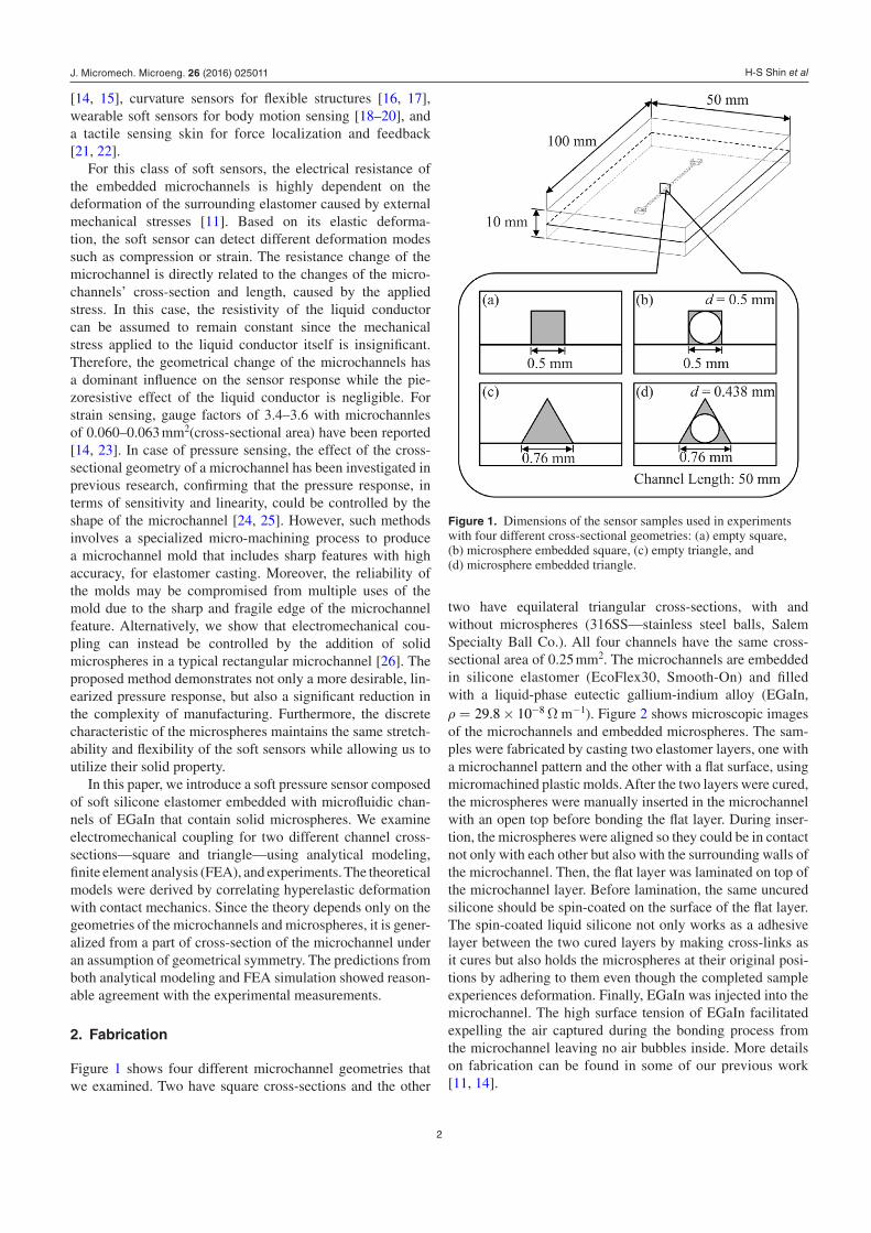
Figure 1 shows four different microchannel geometries that we examined. Two have square cross-sections and the other
two have equilateral triangular cross-sections, with and without microspheres (316SS—stainless steel balls, Salem Specialty Ball Co.). All four channels have the same cross-sectional area of 0.25 mm2. The microchannels are embedded in silicone elastomer (EcoFlex30, Smooth-On) and filled with a liquid-phase eutectic gallium-indium alloy (EGaIn, ρ = × −29.8 10 8 Ω m−1). Figure 2 shows microscopic images of the microchannels and embedded microspheres. The sam-ples were fabricated by casting two elastomer layers, one with a microchannel pattern and the other with a flat surface, using micromachined plastic molds. After the two layers were cured, the microspheres were manually inserted in the microchannel with an open top before bonding the flat layer. During inser-tion, the microspheres were aligned so they could be in contact not only with each other but also with the surrounding walls of the microchannel. Then, the flat layer was laminated on top of the microchannel layer. Before lamination, the same uncured silicone should be spin-coated on the surface of the flat layer. The spin-coated liquid silicone not only works as a adhesive layer between the two cured layers by making cross-links as it cures but also holds the microspheres at their original posi-tions by adhering to them even though the completed sample experiences deformation. Finally, EGaIn was injected into the microchannel. The high surface tension of EGaIn facilitated expelling the air captured during the bonding process from the microchannel leaving no air bubbles inside. More details on fabrication can be found in some of our previous work [11, 14].
Figure 1. Dimensions of the sensor samples used in experiments with four different cross-sectional geometries: (a) empty square, (b) microsphere embedded square, (c) empty triangle, and (d) microsphere embedded triangle.
J. Micromech. Microeng. 26 (2016) 025011
H-S Shin et al
3
3. Theory
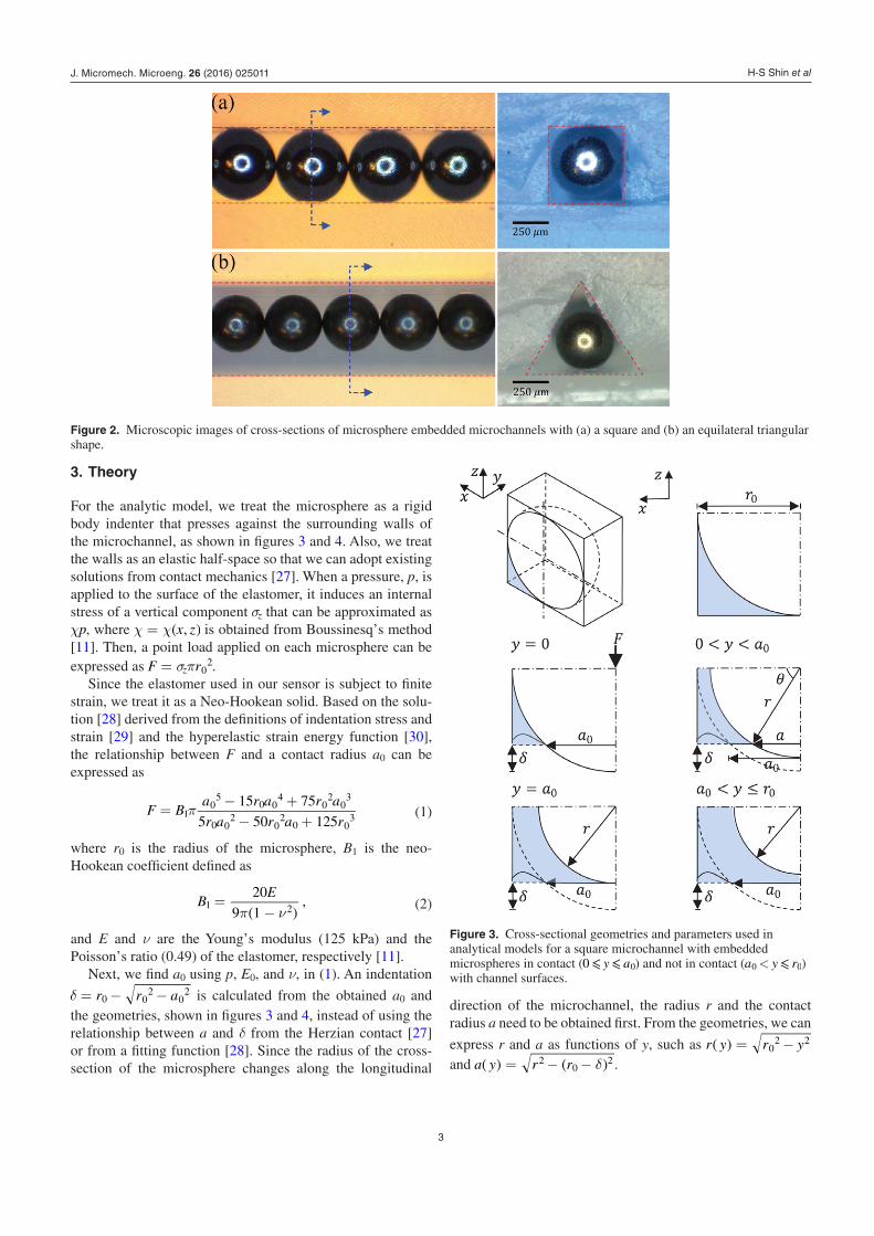
For the analytic model, we treat the microsphere as a rigid body indenter that presses against the surrounding walls of the microchannel, as shown in figures 3 and 4. Also, we treat the walls as an elastic half-space so that we can adopt existing solutions from contact mechanics [27]. When a pressure, p, is applied to the surface of the elastomer, it induces an internal stress of a vertical component σz that can be approximated as χp, where ( )χ χ= x z, is obtained from Boussinesq’s method [11]. Then, a point load applied on each microsphere can be expressed as σπ=F rz 0
2.Since the elastomer used in our sensor is subject to finite
strain, we treat it as a Neo-Hookean solid. Based on the solu-tion [28] derived from the definitions of indentation stress and strain [29] and the hyperelastic strain energy function [30], the relationship between F and a contact radius a0 can be expressed as
π=− +− +
F Ba r a r a
r a r a r
15 75
5 50 1251
05
0 04
02
03
0 02
02
0 03 (1)
where r0 is the radius of the microsphere, B1 is the neo-Hookean coefficient defined as
( )π ν=
−B
E20
9 1,1 2 (2)
and E and ν are the Young’s modulus (125 kPa) and the Poisson’s ratio (0.49) of the elastomer, respectively [11].
Next, we find a0 using p, E0, and ν, in (1). An indentation
δ = − −r r a0 02
02 is calculated from the obtained a0 and
the geometries, shown in figures 3 and 4, instead of using the relationship between a and δ from the Herzian contact [27] or from a fitting function [28]. Since the radius of the cross-section of the microsphere changes along the longitudinal
direction of the microchannel, the radius r and the contact radius a need to be obtained first. From the geometries, we can
express r and a as functions of y, such as ( ) = −r y r y02 2
and ( ) ( )δ= − −a y r r20
2 .
Figure 2. Microscopic images of cross-sections of microsphere embedded microchannels with (a) a square and (b) an equilateral triangular shape.
Figure 3. Cross-sectional geometries and parameters used in analytical models for a square microchannel with embedded microspheres in contact ( ⩽ ⩽y a0 0) and not in contact ( ⩽<a y r0 0) with channel surfaces.
J. Micromech. Microeng. 26 (2016) 025011

H-S Shin et al
4
3.1. Area calculation of square channel
In case of square microchannels, the quarter space of the microchannel cross-section with a microsphere is used, as shown in figure 3, assuming symmetry of cross-sectional deformation. In this case, the displacement of the side wall in x-axis was not taken into account assuming the deformation in x-axis is negligible. Based on a0, the regions along the y-axis can be divided into two cases: in contact ( ⩽ ⩽y a0 0) and not in contact ( ⩽ ⩽a y r0 0), as shown in figure 3. The cross-sectional area, A1( y ), of the regions in contact can be approximated as
( ) ( ) ( ) ⎡⎣⎢
⎤⎦⎥δ δ θ= − − − +A y r r a r r4
1
21 0 0 0
2 (3)
where the angle ( ) (( ) )θ δ= −y r rarcsin /0 . Also, the cross-sectional area not in contact can be expressed as
( ) ( )⎧⎨⎩
⎫⎬⎭
δπ
= − −A y r rr
44
.2 0 0
2
(4)
3.2. Area calculation of triangular channel
In the triangular channel case, a one-sixth portion of the microchannel with a microsphere is examined in the model. Similar to the square channels, the regions are also divided into the ones in contact and not in contact. The cross-sectional area of the deformed region in contact, in figure 4, can be approximated as
A y s s l s m s n r a a r1
2
1
2,1 0 0
2( ) ( )( )( ) ( )( )δ θ= − − − + − − −
(5)where s = (l + m + n)/2 in Heron’s formula for area calcula-tion of a triangle, ( ) δ= − +l w a0
2, m = r0, ( )π=n w/cos /6 , and ( ( ))θ π δ= − −a r/3 arctan / 0 .
Similarly, the area of the deformed regions not in contact can be approximated as
( ) ( )( )( ) ( )δ π= − − − + − −A y s s l s m s n a r r
1
2 6.2 0 0
2
(6)Since the tractions applied on the side walls are half of
those on the bottom wall, we need to distinguish the case of the side walls from that of the bottom wall and to apply a point load, F/2, to the side walls. In addition, the area should be calculated as = +A A A2 4bottom side in both A1 and A2 since there are two sections on the bottom of the triangular channel and four sections on the sides.
3.3. Electrical resistance calculation
For both cases of square and triangular channels, we can obtain the electrical resistance by numerically integrating A1 and A2, along the y-axis:
( ) ∫ ∫ρ ρ
= +R yA
yA
yd d .a
a
r
0 1 2
0
0
0
(7)
4. Simulation
We implemented a series of three-dimensional (3D) stress simulations for predicting the deformation of an incompress-ible silicone rubber (E = 125 kPa and ν = 0.49) affected by embedded microspheres (E = 205 GPa and ν = 0.275) using a commercial FEA software package (ABAQUS/CAE 6.13-3, Dassualt System). In order to reduce the process time, we reduced the size of the models, as shown in figure 5. For boundary conditions, the surfaces of the model in the bottom and left end were fixed and the left end surface with the microspheres was allowed to move only in y-axis. The other parts were fixed only in z-axis. In addition to the boundary conditions, a pressure with linear increaments (0 kPa to 70 kPa) was applied on the top surface with a fixed width (12.5 mm). Frictionless contact condition was applied to both the contacts of the microchannel itself (self-contact) and the contacts between the channel walls and microspheres (surface contact). A neo-Hookean model was used with coef-ficients C10 = 0.02097 and D1 = 0.96 in ABAQUS/CAE [31]. These coefficients were found using the bulk modulus of the silicone rubber, which was obtained by Lamé parameters [32] with given E and ν. Based on the coordinates of the deformed microchannel, the estimated area changes of the microchan-nels calculated in post-processes were used to evaluate the changes of the electrical resistance.
As shown in figure 5, the shape of each corner of the micro-channel with embedded microspheres is similar to that of a
Figure 4. Cross-sectional geometries and parameters used in analytical models for an equilateral triangular microchannel with embedded microspheres in contact ( ⩽ ⩽y a0 0) and not in contact ( ⩽<a y r0 0) with channel surfaces.
J. Micromech. Microeng. 26 (2016) 025011

H-S Shin et al
5
microchannel with a concave triangular cross-section, which has been both analytically and experimentally proven to improve the linearity of pressure response [24].
5. Results
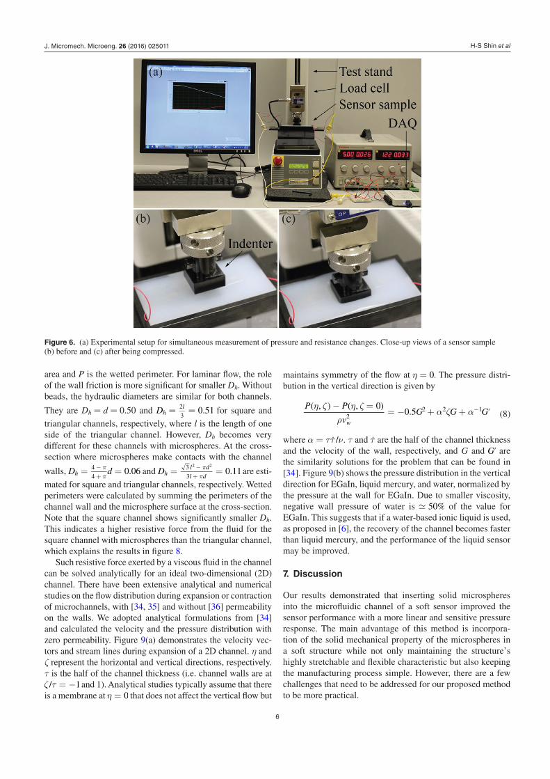
Figure 6 shows the overall experimental setup for measuring pressure and resistance changes simultaneously. Each sample was tested by applying a normal pressure at the center of the top surface using a flat square indenter (25 mm × 25 mm) up to 70 kPa, as shown in figures 6(b) and (c). A load was gradually increased on this pressure area at a rate of 1 mm s−1 using a motorized materials test stand (ESM301, Mark-10) and simultaneously measured using a commercial single-axis load cell (STL-50, AmCells). For sensor output reading, a series circuit of a 10Ω resistor and a current source of 100 mA was constructed. The voltage output was obtained by a data acquisition software (LabVIEW 2010, National Instruments Corp.) through a data acquisition board (NI myDAQ, National Instrument Corp.) and then converted to the ratio of resistance change ∆R R/ 0. The data were collected at a sampling rate of 100 Hz.
Figure 7 shows the experimental results of the microsphere embedded channels (solid blue lines) and empty channels (solid red lines) for both square figure 7(a) and triangular figure 7(b) cross-sections. The theoretical and FEA predic-tions, in the same plots, showed reasonable agreements with the experimental results, confirming the significant improve-ments in linearity, sensitivity at low pressure, and also in
dynamic ranges of the signals. The differences between the experimental results and the predictions are mainly from the inaccurate material properties for modeling and simulation and also from the manufacturing tolerances in the experi-ments. The dotted blue lines show the resistance changes evaluated from equation (7), based on the same dimensions of the prepared samples and an applied pressure p ranging from 0 kPa to 70 kPa. The FEA simulation results were shown with dashed blue lines in the same figure.
Taking advantage of the geometrical benefit, the micro-channels with microspheres showed more of a linear response than regular empty channels, resulting in higher sensitivities at low pressure and larger dynamic ranges.
6. Hysteresis analysis
It is well known that soft structures show relatively large hyster-esis when returning to their original shapes after experiencing deformation even though the external force was removed. This is mainly due to the viscoelastic effect of the base polymer. Such hysteresis has been previously reported in soft micro-fluidic sensors [14, 24, 33] and also in our sensor samples, as shown in figure 8, since the viscoelasticicty of the polymer causes a time delay for the conductive fluid to physically move in the microchannel even after the release of deformation (i.e. pressure). However, the recovery of the channel shape by the elastic force is also resisted by the viscous fluid within the channel. This aspect can be addressed by employing the
hydraulic diameter =DhA
P
4 , where A is the cross sectional
Figure 5. 3D FEA simulation models of halves of (a) a square and (b) an equilateral triangular channel with embedded solid microspheres showing original (left) and deformed (right) channel shapes with a normal pressure.
J. Micromech. Microeng. 26 (2016) 025011
H-S Shin et al
6
area and P is the wetted perimeter. For laminar flow, the role of the wall friction is more significant for smaller Dh. Without beads, the hydraulic diameters are similar for both channels.
They are Dh = d = 0.50 and = =D 0.51hl2
3 for square and
triangular channels, respectively, where l is the length of one side of the triangular channel. However, Dh becomes very different for these channels with microspheres. At the cross-section where microspheres make contacts with the channel
walls, = =ππ−+
D d 0.06h4
4 and = =π
π−+
D 0.11hl d
l d
3
3
2 2
are esti-
mated for square and triangular channels, respectively. Wetted perimeters were calculated by summing the perimeters of the channel wall and the microsphere surface at the cross-section. Note that the square channel shows significantly smaller Dh. This indicates a higher resistive force from the fluid for the square channel with microspheres than the triangular channel, which explains the results in figure 8.
Such resistive force exerted by a viscous fluid in the channel can be solved analytically for an ideal two-dimensional (2D) channel. There have been extensive analytical and numerical studies on the flow distribution during expansion or contraction of microchannels, with [34, 35] and without [36] permeability on the walls. We adopted analytical formulations from [34] and calculated the velocity and the pressure distribution with zero permeability. Figure 9(a) demonstrates the velocity vec-tors and stream lines during expansion of a 2D channel. η and ζ represent the horizontal and vertical directions, respectively. τ is the half of the channel thickness (i.e. channel walls are at ζ τ = −/ 1 and 1). Analytical studies typically assume that there is a membrane at η = 0 that does not affect the vertical flow but
maintains symmetry of the flow at η = 0. The pressure distri-bution in the vertical direction is given by
( ) ( )η ζ η ζρ
α ζ α− =
= − + + ′−P P
vG G G
, , 00.5
w2
2 2 1 (8)
where α ττ ν= ˙ / . τ and τ are the half of the channel thickness and the velocity of the wall, respectively, and G and ′G are the similarity solutions for the problem that can be found in [34]. Figure 9(b) shows the pressure distribution in the vertical direction for EGaIn, liquid mercury, and water, normalized by the pressure at the wall for EGaIn. Due to smaller viscosity, negative wall pressure of water is 50% of the value for EGaIn. This suggests that if a water-based ionic liquid is used, as proposed in [6], the recovery of the channel becomes faster than liquid mercury, and the performance of the liquid sensor may be improved.
7. Discussion
Our results demonstrated that inserting solid microspheres into the microfluidic channel of a soft sensor improved the sensor performance with a more linear and sensitive pressure response. The main advantage of this method is incorpora-tion of the solid mechanical property of the microspheres in a soft structure while not only maintaining the structure’s highly stretchable and flexible characteristic but also keeping the manufacturing process simple. However, there are a few challenges that need to be addressed for our proposed method to be more practical.
Figure 6. (a) Experimental setup for simultaneous measurement of pressure and resistance changes. Close-up views of a sensor sample (b) before and (c) after being compressed.
J. Micromech. Microeng. 26 (2016) 025011

H-S Shin et al
7
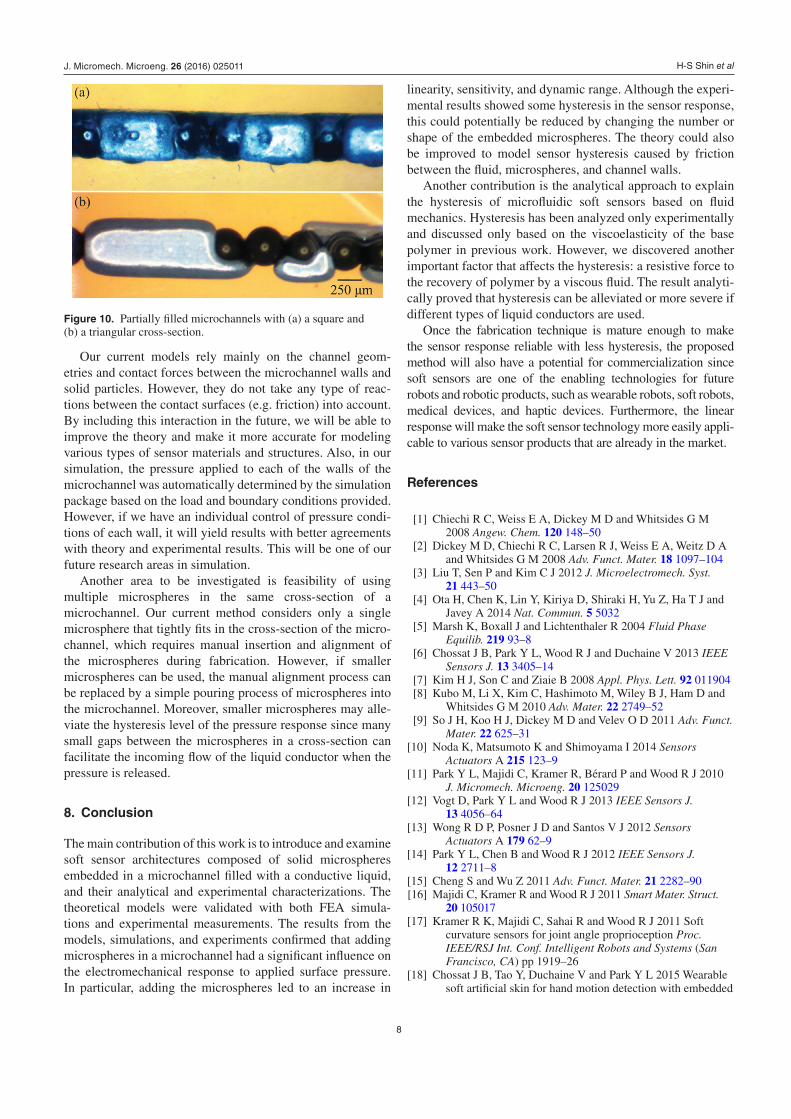
The current fabrication method is also another challenge since it does not always guarantee complete filling of the liquid metal in the microchannel. When a flat layer is lami-nated on the microchannel layer with microspheres, part of the uncured thin silicone coating, used as a bonding agent, some-times flows into the small gaps between the microspheres and the channel walls, resulting in blockages in the microchannel, as shown in figure 10. This reduces the amount of the liquid metal to be injected, increasing the resistance in an unpredict-able way. Therefore, this irregular microchannel could not only be a source of an inconsistent sensitivity of the sensor but also cause increase in the hysteresis level. One possible solution is to find a better way of controlling the thickness of the uncured silicone coating [37], which will minimize the amount of silicone necessary for bonding. There have been various techniques proposed for bonding PDMS layers, such as oxygen plasma bonding [38], stamp and stick (SAS) transfer bonding [39], and corona discharge [40]. Further investigation on more efficient bonding processes based on the above tech-niques will be one of our immediate future research areas.
Figure 7. Pressure responses of (a) square and (b) equilateral triangular channels without (red) and with (blue) microspheres. Color bands denotate the standard deviation of five trials. Theoretical predictions and FEA simulation results of microsphere embedded channels are shown with dotted lines and dashed lines, respectively.
Figure 8. Experimental results of hysteresis analysis for a square (blue) and a triangular (red) microchannel with presure loading-unloading loops. The triangular channel shows slightly less hysteresis due to the larger spaces in the channel that facilitate the flow of the liquid conductor.
Figure 9. (a) Stream lines and velocity vectors during the expansion of a two-dimensional channel. (b) Pressure distribution in the vertical direction for EGaIn (red solid), liquid mercury (blue dashed) and water (black dotdash), normalized by the pressure at the wall for EGaIn.
J. Micromech. Microeng. 26 (2016) 025011
H-S Shin et al
8
Our current models rely mainly on the channel geom-etries and contact forces between the microchannel walls and solid particles. However, they do not take any type of reac-tions between the contact surfaces (e.g. friction) into account. By including this interaction in the future, we will be able to improve the theory and make it more accurate for modeling various types of sensor materials and structures. Also, in our simulation, the pressure applied to each of the walls of the microchannel was automatically determined by the simulation package based on the load and boundary conditions provided. However, if we have an individual control of pressure condi-tions of each wall, it will yield results with better agreements with theory and experimental results. This will be one of our future research areas in simulation.
Another area to be investigated is feasibility of using multiple microspheres in the same cross-section of a microchannel. Our current method considers only a single microsphere that tightly fits in the cross-section of the micro-channel, which requires manual insertion and alignment of the microspheres during fabrication. However, if smaller microspheres can be used, the manual alignment process can be replaced by a simple pouring process of microspheres into the microchannel. Moreover, smaller microspheres may alle-viate the hysteresis level of the pressure response since many small gaps between the microspheres in a cross-section can facilitate the incoming flow of the liquid conductor when the pressure is released.
8. Conclusion
The main contribution of this work is to introduce and examine soft sensor architectures composed of solid microspheres embedded in a microchannel filled with a conductive liquid, and their analytical and experimental characterizations. The theoretical models were validated with both FEA simula-tions and experimental measurements. The results from the models, simulations, and experiments confirmed that adding microspheres in a microchannel had a significant influence on the electromechanical response to applied surface pressure. In particular, adding the microspheres led to an increase in
linearity, sensitivity, and dynamic range. Although the experi-mental results showed some hysteresis in the sensor response, this could potentially be reduced by changing the number or shape of the embedded microspheres. The theory could also be improved to model sensor hysteresis caused by friction between the fluid, microspheres, and channel walls.
Another contribution is the analytical approach to explain the hysteresis of microfluidic soft sensors based on fluid mechanics. Hysteresis has been analyzed only experimentally and discussed only based on the viscoelasticity of the base polymer in previous work. However, we discovered another important factor that affects the hysteresis: a resistive force to the recovery of polymer by a viscous fluid. The result analyti-cally proved that hysteresis can be alleviated or more severe if different types of liquid conductors are used.
Once the fabrication technique is mature enough to make the sensor response reliable with less hysteresis, the proposed method will also have a potential for commercialization since soft sensors are one of the enabling technologies for future robots and robotic products, such as wearable robots, soft robots, medical devices, and haptic devices. Furthermore, the linear response will make the soft sensor technology more easily appli-cable to various sensor products that are already in the market.
References
[1] Chiechi R C, Weiss E A, Dickey M D and Whitsides G M 2008 Angew. Chem. 120 148–50
[2] Dickey M D, Chiechi R C, Larsen R J, Weiss E A, Weitz D A and Whitsides G M 2008 Adv. Funct. Mater. 18 1097–104
[3] Liu T, Sen P and Kim C J 2012 J. Microelectromech. Syst. 21 443–50
[4] Ota H, Chen K, Lin Y, Kiriya D, Shiraki H, Yu Z, Ha T J and Javey A 2014 Nat. Commun. 5 5032
[5] Marsh K, Boxall J and Lichtenthaler R 2004 Fluid Phase Equilib. 219 93–8
[6] Chossat J B, Park Y L, Wood R J and Duchaine V 2013 IEEE Sensors J. 13 3405–14
[7] Kim H J, Son C and Ziaie B 2008 Appl. Phys. Lett. 92 011904 [8] Kubo M, Li X, Kim C, Hashimoto M, Wiley B J, Ham D and
Whitsides G M 2010 Adv. Mater. 22 2749–52 [9] So J H, Koo H J, Dickey M D and Velev O D 2011 Adv. Funct.
Mater. 22 625–31 [10] Noda K, Matsumoto K and Shimoyama I 2014 Sensors
Actuators A 215 123–9 [11] Park Y L, Majidi C, Kramer R, Bérard P and Wood R J 2010
J. Micromech. Microeng. 20 125029 [12] Vogt D, Park Y L and Wood R J 2013 IEEE Sensors J.
13 4056–64 [13] Wong R D P, Posner J D and Santos V J 2012 Sensors
Actuators A 179 62–9 [14] Park Y L, Chen B and Wood R J 2012 IEEE Sensors J.
12 2711–8 [15] Cheng S and Wu Z 2011 Adv. Funct. Mater. 21 2282–90 [16] Majidi C, Kramer R and Wood R J 2011 Smart Mater. Struct.
20 105017 [17] Kramer R K, Majidi C, Sahai R and Wood R J 2011 Soft
curvature sensors for joint angle proprioception Proc. IEEE/RSJ Int. Conf. Intelligent Robots and Systems (San Francisco, CA) pp 1919–26
[18] Chossat J B, Tao Y, Duchaine V and Park Y L 2015 Wearable soft artificial skin for hand motion detection with embedded
Figure 10. Partially filled microchannels with (a) a square and (b) a triangular cross-section.
J. Micromech. Microeng. 26 (2016) 025011

H-S Shin et al
9
microfluidic strain sensing Proc. IEEE Int. Conf. Robots and Automation (Seattle, WA) pp 2568–73
[19] Kramer R, Majidi C and Wood R J 2011 Wearable tactile keypad with stretchable artificial skin Proc. IEEE Int. Conf. Robots and Automation (Sahanghai, China) pp 1103–7
[20] Menguc Y, Park Y L, Pei H, Vogt D, Aubin P, Fluke L, Winchell E, Stirling L, Wood R J and Walsh C J 2014 Int. J. Robot. Res. 33 1748–64
[21] Chossat J B, Shin H S, Park Y L and Duchaine V 2015 ASME J. Mech. Robot. 7 021008
[22] Hammond F L III, Kramer R K, Wan Q, Howe R D and Wood R J 2014 IEEE Sensors J. 14 1443–52
[23] Park Y L, Chen B, Pérez-Arancibia N O, Young D, Stirling L, Wood R J, Goldfield E C and Nagpal R 2014 Bioinspiration Biomimetics 9 016007
[24] Park Y L, Tepayotl-Ramirez D, Wood R J and Majidi C 2012 Appl. Phys. Lett. 101 191904
[25] Tepayotl-Ramirez D, Lu T, Park Y L and Majidi C 2013 Appl. Phys. Lett. 102 044102
[26] Shin H S and Park Y L 2014 Improved pressure response with embedded solid microbeads in microfluidic soft sensors Proc. IEEE Sensors Conf. (Valencia, Spain) pp 1788–91
[27] Johnson K L and Johnson K L 1987 Contact Mechanics (Cambridge: Cambridge University Press)
[28] Lin D C, Shreiber D I, Dimitriadis E K and Horkay F 2009 Biomech. Model. Mechanobiol. 8 345–58
[29] Tabor D 1951 The Hardness of Metals (Oxford: Clarendon) [30] Mooney M 1940 J. Appl. Phys. 11 582–92 [31] ABAQUS 2013, ABAQUS 6.13 documentation, Dassault
Systèms, Providence, RI, USA [32] Salençon J 2001 Handbook of Continuum Mechanics:
General Concepts-Thermoelasticity (New York: Springer)
[33] Michaud H O, Teixidor J and Lacour S P 2015 Smart Mater. Struct. 24 035020
[34] Majdalani J, Zhou C and Dawson C A 2002 J. Biomech. 35 1399–403
[35] Asghar S, Mushtaq M and Hayat T 2010 Nonlinear Anal. Real World Appl. 11 555–61
[36] Uchida S and Aoki H 1977 J. Fluid Mech. 82 371–87 [37] Schmidt R H, Mosbach K and Haupt K 2004 Adv. Mater.
16 719–22 [38] Eddings M A, Johnson M A and Gale B K 2008 J. Micromech.
Microeng. 18 067001 [39] Satyanarayana S, Karnik R N and Majumdar A 2005
J. Microelectromech. Syst. 14 392–99 [40] Haubert K, Drier T and Beebe D 2006 Lab Chip
6 1548–9
J. Micromech. Microeng. 26 (2016) 025011