english (translated from italian) english (translated from ... · uni en 1127-1:2011; uni en...
TRANSCRIPT
ENGLISH (Translated from Italian) ENGLISH (Translated from Italian) ENGLISH (Translated from Italian) ENGLISH (Translated from Italian) ENGLISH (Translated from Italian) ENGLISH (Translated from Italian)
Bulletin M0268 ITEN _ 00
PIUSI S.p.A.Suzzara (MN) Italy
K33
MANUALE D’USO E MANUTENZIONE
USE AND MAINTENANCE MANUAL
Bulletin M0268 ITEN _ 00
IT
EN
Atex
A TABLE OF CONTENTS
A TABLE OF CONTENTS B CONFORMITY B1 DECLARATION OF CONFORMITY (94/9/CE, Annex X, lett. B)
C MACHINE DESCRIPTION C1 DEFINITION OF CLASSIFIED ZONES C2 INTENDED USE C3 HANDLING AND TRANSPORT D GENERAL WARNINGS E FIRST AID RULES F GENERAL SAFETY RULES G TECHNICAL DATA H OPERATING CONDITIONS H1 ENVIRONMENTAL CONDITIONS H2 FLUIDS PERMITTED I INSTALLATION L CALIBRATION M EVERY DAY USE N MAINTENANCE O DISASSEMBLING REASSEMBLING P PROBLEMS, CAUSES AND SOLUTIONS Q DEMOLITION AND DISPOSAL R EXPLODED VIEW
B CONFORMITY
B1 DECLARATION OF CONFORMITY (94/9/CE, Annex X, lett. B)
The manufacturer: PIUSI S.p.A. Via Pacinotti, 16/A 46029 Suzzara (MN) Italy
Declares under its own responsibility that the machine:Type: MeterModel: K33 ATEXYear of manufacture: refer to the year of production shown on the CE plate affixed to the prod-uct.CERTIFIES THATcomply with all relevant provisions of the following directives:- 94/9/CE and the following harmonized standards, applied standards and/or technical specifications:UNI EN 1127-1:2011; UNI EN 13463-1:2009; UNI EN 13463-5:2011 This equipment is classified as follows: Group II, category 2 G c IIB T=85° C (T6)
Read the Use and Maintenance manual before using the pump..
Place: Suzzara (Mn) Date: 01/03/2014 Legal Representative
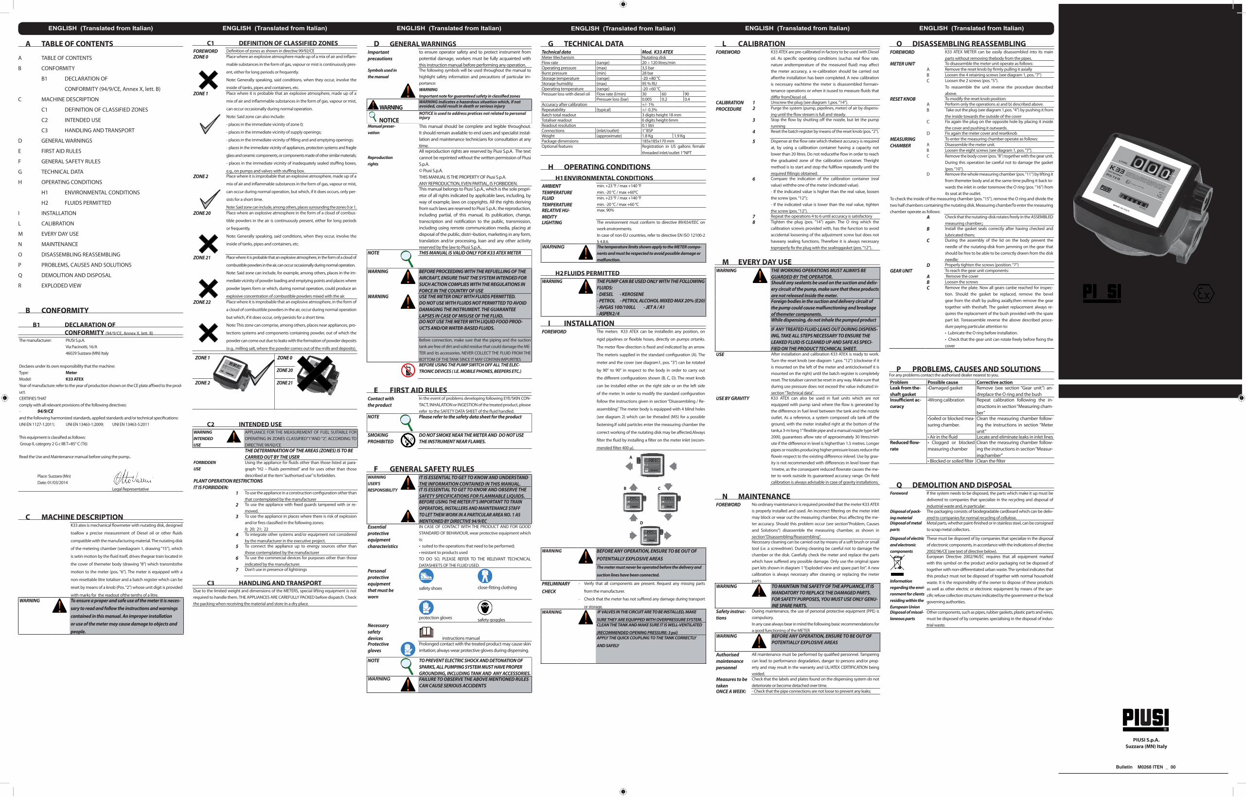
C MACHINE DESCRIPTIONK33 atex is mechanical flowmeter with nutating disk, designed
toallow a precise measurement of Diesel oil or other fluids
compatible with the manufacturing material. The nutating disk
of the metering chamber (seediagram 1, drawing “15”), which
is setin motion by the fluid itself, drives thegear train located in
the cover of themeter body (drawing “8”) which transmitsthe
motion to the meter (pos. “6”). The meter is equipped with a
non-resettable litre totaliser and a batch register which can be
reset by means of a knob (Pos. “2”) whose unit digit is provided
with marks for the readout ofthe tenths of a litre.WARNING To ensure a proper and safe use of the meter it is neces-
sary to read and follow the instructions and warnings contained in this manual. An improper installation or use of the meter may cause damage to objects and people.
C1 DEFINITION OF CLASSIFIED ZONES FOREWORD Definition of zones as shown in directive 99/92/CEZONE 0
Place where an explosive atmosphere made up of a mix of air and inflam-
mable substances in the form of gas, vapour or mist is continuously pres-
ent, either for long periods or frequently.
Note: Generally speaking, said conditions, when they occur, involve the
inside of tanks, pipes and containers, etc.ZONE 1
Place where it is probable that an explosive atmosphere, made up of a
mix of air and inflammable substances in the form of gas, vapour or mist,
can occur occasionally during normal operation.
Note: Said zone can also include:
- places in the immediate vicinity of zone 0;
- places in the immediate vicinity of supply openings;
- places in the immediate vicinity of filling and and emptying openings;
- places in the immediate vicinity of appliances, protection systems and fragile
glass and ceramic components, or components made of other similar materials;
- places in the immediate vicinity of inadequately sealed stuffing boxes,
e.g., on pumps and valves with stuffing box.ZONE 2
Place where it is improbable that an explosive atmosphere, made up of a
mix of air and inflammable substances in the form of gas, vapour or mist,
can occur during normal operation, but which, if it does occurs, only per-
sists for a short time.
Note: Said zone can include, among others, places surrounding the zones 0 or 1.ZONE 20
Place where an explosive atmosphere in the form of a cloud of combus-
tible powders in the air is continuously present, either for long periods
or frequently.
Note: Generally speaking, said conditions, when they occur, involve the
inside of tanks, pipes and containers, etc.
ZONE 21
Place where it is probable that an explosive atmosphere, in the form of a cloud of
combustible powders in the air, can occur occasionally during normal operation.
Note: Said zone can include, for example, among others, places in the im-
mediate vicinity of powder loading and emptying points and places where
powder layers form or which, during normal operation, could produce an
explosive concentration of combustible powders mixed with the air.ZONE 22
Place where it is improbable that an explosive atmosphere, in the form of
a cloud of combustible powders in the air, occur during normal operation
but which, if it does occur, only persists for a short time.
Note: This zone can comprise, among others, places near appliances, pro-
tections systems and components containing powder, out of which the
powder can come out due to leaks with the formation of powder deposits
(e.g., milling salt, where the powder comes out of the mills and deposits).
ZONE 1 ZONE 0
ZONE 20
ZONE 2 ZONE 21
C2 INTENDED USEWARNINGINTENDED USE
APPLIANCE FOR THE MEASUREMENT OF FUEL SUITABLE FOR OPERATING IN ZONES CLASSIFIED“1”AND “2”, ACCORDING TO DIRECTIVE 99/92/CETHE DETERMINATION OF THE AREAS (ZONES) IS TO BE CARRIED OUT BY THE USER
FORBIDDEN USE
Using the appliance for fluids other than those listed at para-graph “H2 – Fluids permitted” and for uses other than those described at the item “authorised use” is forbidden.
PLANT OPERATION RESTRICTIONSIT IS FORBIDDEN:
1 To use the appliance in a construction configuration other than that contemplated by the manufacturer
2 To use the appliance with fixed guards tampered with or re-moved.
3 To use the appliance in places where there is risk of explosion and/or fires classified in the following zones:0; 20; 21; 22
4 To integrate other systems and/or equipment not considered by the manufacturer in the executive project.
5 To connect the appliance up to energy sources other than those contemplated by the manufacturer
6 To use the commercial devices for purposes other than those indicated by the manufacturer.
7 Don’t use in presence of lightnings
C3 HANDLING AND TRANSPORTDue to the limited weight and dimensions of the METERS, special lifting equipment is not required to handle them. THE APPLIANCES ARE CAREFULLY PACKED before dispatch. Check the packing when receiving the material and store in a dry place.
D GENERAL WARNINGSImportant precautions
to ensure operator safety and to protect instrument from potential damage, workers must be fully acquainted with this instruction manual before performing any operation.
Symbols used in the manual
The following symbols will be used throughout the manual to highlight safety information and precautions of particular im-portance:WARNINGImportant note for guaranteed safety in classified zones
WARNINGWARNING indicates a hazardous situation which, if not avoided, could result in death or serious injury
NOTICENOTICE is used to address pratices not related to personal injury
Manual preser-vation
This manual should be complete and legible throughout. It should remain available to end users and specialist instal-lation and maintenance technicians for consultation at any time.
Reproduction rights
All reproduction rights are reserved by Piusi S.p.A. The text cannot be reprinted without the written permission of Piusi S.p.A.© Piusi S.p.A.THIS MANUAL IS THE PROPERTY OF Piusi S.p.A.ANY REPRODUCTION, EVEN PARTIAL, IS FORBIDDEN.This manual belongs to Piusi S.p.A., which is the sole propri-etor of all rights indicated by applicable laws, including, by way of example, laws on copyrights. All the rights deriving from such laws are reserved to Piusi S.p.A.: the reproduction, including partial, of this manual, its publication, change, transcription and notification to the public, transmission, including using remote communication media, placing at disposal of the public, distri¬bution, marketing in any form, translation and/or processing, loan and any other activity reserved by the law to Piusi S.p.A..
NOTE THIS MANUAL IS VALID ONLY FOR K33 ATEX METER
WARNING BEFORE PROCEEDING WITH THE REFUELLING OF THE AIRCRAFT, ENSURE THAT THE SYSTEM INTENDED FOR SUCH ACTION COMPLIES WITH THE REGULATIONS IN FORCE IN THE COUNTRY OF USE
WARNING USE THE METER ONLY WITH FLUIDS PERMITTED. DO NOT USE WITH FLUIDS NOT PERMITTED TO AVOID DAMAGING THE INSTRUMENT. THE GUARANTEE LAPSES IN CASE OF MISUSE OF THE FLUID.DO NOT USE THE METER WITH LIQUID FOOD PROD-UCTS AND/OR WATER-BASED FLUIDS.
Before connection, make sure that the piping and the suction tank are free of dirt and solid residue that could damage the ME-TER and its accessories. NEVER COLLECT THE FLUID FROM THE BOTTOM OF THE TANK SINCE IT MAY CONTAIN IMPURITIESBEFORE USING THE PUMP SWITCH OFF ALL THE ELEC-TRONIC DEVICES ( I.E. MOBILE PHONES, BEEPERS ETC.)
E FIRST AID RULESContact with the product
In the event of problems developing following EYE/SKIN CON-TACT, INHALATION or INGESTION of the treated product, please refer to the SAFETY DATA SHEET of the fluid handled.
NOTE Please refer to the safety data sheet for the product
SMOKING PROHIBITED
DO NOT SMOKE NEAR THE METER AND DO NOT USE THE INSTRUMENT NEAR FLAMES.
F GENERAL SAFETY RULESWARNINGUSER'SRESPONSIBILITY
IT IS ESSENTIAL TO GET TO KNOW AND UNDERSTAND THE INFORMATION CONTAINED IN THIS MANUAL.IT IS ESSENTIAL TO GET TO KNOW AND OBSERVE THE SAFETY SPECIFICATIONS FOR FLAMMABLE LIQUIDS.BEFORE USING THE METER IT’S IMPORTANT TO TRAIN OPERATORS, INSTALLERS AND MAINTENANCE STAFF TO LET THEM WORK IN A PARTICULAR AREA NO. 1 AS MENTIONED BY DIRECTIVE 94/9/EC
Essential protective equipment characteristics
IN CASE OF CONTACT WITH THE PRODUCT AND FOR GOOD STANDARD OF BEHAVIOUR, wear protective equipment which is:• suited to the operations that need to be performed;• resistant to products usedTO DO SO, PLEASE REFER TO THE RELEVANT TECHCNICAL DATASHEETS OF THE FLUID USED.
Personal protective equipment that must be worn
safety shoes close-fitting clothing
protection gloves safety gogglesNecessary safetydevices instructions manualProtective gloves
Prolonged contact with the treated product may cause skin irritation; always wear protective gloves during dispensing.
NOTE TO PREVENT ELECTRIC SHOCK AND DETONATION OF SPARKS, ALL PUMPING SYSTEM MUST HAVE PROPER GROUNDING, INCLUDING TANK AND ANY ACCESSORIES.
WARNING FAILURE TO OBSERVE THE ABOVE MENTIONED RULES CAN CAUSE SERIOUS ACCIDENTS
G TECHNICAL DATATechnical data Mod. K33 ATEXMeter Mechanism Nutating diskFlow rate (range) 20 ÷ 120 litres/minOperating pressure (max) 3,5 barBurst pressure (min) 28 barStorage temperature (range) -20 +80 °CStorage humidity (max) 95 % RUOperating temperature (range) -20 +60 °CPressuer loss with diesel oil Flow rate (l/min) 30 60 90
Pressuer loss (bar) 0.005 0.2 0.4Accuracy after calibration +/- 1%Repeatability (typical) +/- 0.3%Batch total readout 3 digits height 18 mmTotaliser readout 6 digits height 6mmReadout resolution 0.1 litriConnections (inlet/outlet) 1” BSPWeight (approximate) 1.8 Kg 1.9 KgPackage dimensions 185x185x170 mmOptional features Registration in US gallons female
threaded inlet/outlet 1”NPT
H OPERATING CONDITIONSH1 ENVIRONMENTAL CONDITIONS
AMBIENTTEMPERATURE
min. +23 °F / max +140 °Fmin. -20 °C / max +60°C
FLUID TEMPERATURE
min. +23 °F / max +140 °Fmin. -20 °C / max +60 °C
RELATIVE HU-MIDITY
max. 90%
LIGHTING The environment must conform to directive 89/654/EEC on work environments.In case of non-EU countries, refer to directive EN ISO 12100-2 § 4.8.6.
WARNING The temperature limits shown apply to the METER compo-nents and must be respected to avoid possible damage or malfunction.
H2 FLUIDS PERMITTED WARNING THE PUMP CAN BE USED ONLY WITH THE FOLLOWING
FLUIDS: - DIESEL - KEROSENE - PETROL - PETROL ALCOHOL MIXED MAX 20% (E20)- AVGAS 100/100LL - JET A / A1- ASPEN 2 / 4
I INSTALLATIONFOREWORD The meters K33 ATEX can be installedin any position, on
rigid pipelines or flexible hoses, directly on pumps ortanks.
The meter flow direction is fixed and indicated by an arrow.
The meteris supplied in the standard configuration (A). The
meter and the cover (see diagram1, pos. “3”) can be rotated
by 90° to 90° in respect to the body in order to carry out
the different configurations shown (B, C, D). The reset knob
can be installed either on the right side or on the left side
of the meter. In order to modify the standard configuration
follow the instructions given in section “Disassembling / Re-
assembling”. The meter body is equipped with 4 blind holes
(see diagram 2) which can be threaded (M5) for a possible
fastening.If solid particles enter the measuring chamber the
correct working of the nutating disk may be affected.Always
filter the fluid by installing a filter on the meter inlet (recom-
mended filter 400 μ).
A
B C
D
WARNING
BEFORE ANY OPERATION, ENSURE TO BE OUT OF POTENTIALLY EXPLOSIVE AREAS
The meter must never be operated before the delivery and
suction lines have been connected.
PRELIMINARY CHECK
- Verify that all components are present. Request any missing parts
from the manufacturer.
- Check that the meter has not suffered any damage during transport
or storage.WARNING IF VALVES IN THE CIRCUIT ARE TO BE INSTALLED, MAKE
SURE THEY ARE EQUIPPED WITH OVERPRESSURE SYSTEM.CLEAN THE TANK AND MAKE SURE IT IS WELL-VENTILATED
(RECOMMENDED OPENING PRESSURE: 3 psi)APPLY THE QUICK COUPLING TO THE TANK CORRECTLY
AND SAFELY
L CALIBRATIONFOREWORD K33 ATEX are pre-calibrated in factory to be used with Diesel
oil. As specific operating conditions (suchas real flow rate, nature andtemperature of the measured fluid) may affect the meter accuracy, a re-calibration should be carried out afterthe installation has been completed. A new calibration is necessary eachtime the meter is disassembled formain-tenance operations or when it isused to measure fluids that differ fromDiesel oil.
CALIBRATION PROCEDURE
1 Unscrew the plug (see diagram 1,pos. “14”).2 Purge the system (pump, pipelines, meter) of air by dispens-
ing until the flow stream is full and steady.3 Stop the flow by shutting off the nozzle, but let the pump
running4 Reset the batch register by means of the reset knob (pos. “2”).
5 Dispense at the flow rate which thebest accuracy is required at, by using a calibration container having a capacity not lower than 20 litres. Do not reducethe flow in order to reach the graduated zone of the calibration container. Theright method is to start and stop the fullflow repeatedly until the required fillingis obtained.
6 Compare the indication of the calibration container (real value) withthe one of the meter (indicated value).- If the indicated value is higher than the real value, loosen the screw (pos. “12”);- If the indicated value is lower than the real value, tighten the screw (pos. “12”).
7 Repeat the operations 4 to 6 until accuracy is satisfactory8 Tighten the plug (pos. “14”) again. The O ring which the
calibration screwis provided with, has the function to avoid accidental loosening of the adjustment screw but does not haveany sealing functions. Therefore it is always necessary toproperly fix the plug with the sealinggasket (pos. “12”)..
M EVERY DAY USEWARNING THE WORKING OPERATIONS MUST ALWAYS BE
GUARDED BY THE OPERATOR.Should any sealants be used on the suction and deliv-ery circuit of the pump, make sure that these products are not released inside the meter.Foreign bodies in the suction and delivery circuit of the pump could cause malfunctioning and breakage of themeter components.While dispensing, do not inhale the pumped product
IF ANY TREATED FLUID LEAKS OUT DURING DISPENS-ING, TAKE ALL STEPS NECESSARY TO ENSURE THE LEAKED FLUID IS CLEANED UP AND SAFE AS SPECI-FIED ON THE PRODUCT TECHNICAL SHEET.
USE After installation and calibration K33 ATEX is ready to work. Turn the reset knob (see diagram 1,pos. “12”) (clockwise if it is mounted on the left of the meter and anticlockwiseif it is mounted on the right) until the batch register is completely reset. The totaliser cannot be reset in any way. Make sure that during use pressure does not exceed the value indicated in-section “Technical data”.
USE BY GRAVITY K33 ATEX can also be used in fuel units which are not equipped with pump sand where the flow is generated by the difference in fuel level between the tank and the nozzle outlet. As a reference, a system composed ofa tank off the ground, with the meter installed right at the bottom of the tank,a 3-m long 1’’ flexible pipe and a manual nozzle type Self 2000, guarantees aflow rate of approximately 30 litres/min-ute if the difference in level is higherthan 1.5 metres. Longer pipes or nozzles producing higher pressure losses reduce the flowin respect to the existing difference inlevel. Use by grav-ity is not recommended with differences in level lower than 1metre, as the consequent reduced flowrate causes the me-ter to work outside its guaranteed accuracy range. On field calibration is always advisable in case of gravity installations.
N MAINTENANCEFOREWORD No ordinary maintenance is required provided that the meter K33 ATEX
is properly installed and used. An incorrect filtering on the meter inlet may block or wear out the measuring chamber, thus affecting the me-ter accuracy. Should this problem occur (see section”Problem, Causes and Solutions”) disassemble the measuring chamber, as shown in section“Disassembling/Reassembling”.Necessary cleaning can be carried out by means of a soft brush or small tool (i.e. a screwdriver). During cleaning be careful not to damage the chamber or the disk. Carefully check the meter and replace the parts which have suffered any possible damage. Only use the original spare part kits shown in diagram 1 “Exploded view and spare part list”. A new calibration is always necessary after cleaning or replacing the meter parts.
WARNING TO MAINTAIN THE SAFETY OF THE APPLIANCE, IT IS MANDATORY TO REPLACE THE DAMAGED PARTS. FOR SAFETY PURPOSES, YOU MUST USE ONLY GENU-INE SPARE PARTS.
Safety instruc-tions
During maintenance, the use of personal protective equipment (PPE) is compulsory.In any case always bear in mind the following basic recommendations for a good functioning of the METER
WARNING
BEFORE ANY OPERATION, ENSURE TO BE OUT OF POTENTIALLY EXPLOSIVE AREAS
Authorised maintenance personnel
All maintenance must be performed by qualified personnel. Tampering can lead to performance degradation, danger to persons and/or prop-erty and may result in the warranty and UL/ATEX CERTIFICATION being voided.
Measures to be taken
Check that the labels and plates found on the dispensing system do not deteriorate or become detached over time.
ONCE A WEEK: - Check that the pipe connections are not loose to prevent any leaks;
O DISASSEMBLING REASSEMBLINGFOREWORD K33 ATEX METER can be easily disassembled into its main
parts without removing thebody from the pipes. METER UNIT To disassemble the meter unit operate as follows:
A Remove the reset knob by firmly pulling it axiallyB Loosen the 4 retaining screws (see diagram 1, pos. “7”)C Loosen the 2 screws (pos. “5”).
To reassemble the unit reverse the procedure described above.
RESET KNOB To modify the reset knob position:A Perform only the operations a) and b) described above.B Take out the plug (see diagram 1,pos. “4”) by pushing it from
the inside towards the outside of the coverC Fix again the plug on the opposite hole by placing it inside
the cover and pushing it outwards.D Fix again the meter cover and resetknob
MEASURING CHAMBER
To enter the measuring chamber operate as follows:A Disassemble the meter unit.B Loosen the eight screws (see diagram 1, pos. “7”).C Remove the body cover (pos. “8”) together with the gear unit.
During this operation be careful not to damage the gasket (pos. “10”).
D Remove the whole measuring chamber (pos. “11”) by lifting it from themeter body and at the same time pulling it back to-wards the inlet in order toremove the O ring (pos. “16”) from its seat at the outlet.
To check the inside of the measuring chamber (pos. “15”), remove the O ring and divide the two half chambers containing the nutating disk. Measuring chamberTo enter the measuring chamber operate as follows:
A Check that the nutating-disk rotates freely in the ASSEMBLED measuring chamber;;
B Install the gasket seals correctly after having checked and lubricated them;
C During the assembly of the lid on the body prevent the needle of the nutating-disk from jamming on the gear that should be free to be able to be correctly drawn from the disk needle;
D Properly tighten the screws (position. “7”) GEAR UNIT To reach the gear unit components:
A Remove the coverB Loosen the screwsC Remove the plate. Now all gears canbe reached for inspec-
tion. Should the gasket be replaced, remove the bevel gear from the shaft by pulling axially,then remove the gear together with theshaft. The gasket replacement always re-quires the replacement of the bush provided with the spare part kit. Toreassemble reverse the above described proce-dure paying particular attention to:• Lubricate the O ring before installation.• Check that the gear unit can rotate freely before fixing the cover
P PROBLEMS, CAUSES AND SOLUTIONSFor any problems contact the authorised dealer nearest to you.
Problem Possible cause Corrective actionLeak from the-shaft gasket
•Damaged gasket Remove (see section “Gear unit”) an-dreplace the O ring and the bush
Insufficient ac-curacy
•Wrong calibration Repeat calibration following the in-structions in section “Measuring cham-ber”
•Soiled or blocked mea-suring chamber.
Clean the measuring chamber follow-ing the instructions in section “Meter unit”
• Air in the fluid Locate and eliminate leaks in inlet linesReduced flow-rate
• Clogged or blocked measuring chamber
Clean the measuring chamber follow-ing the instructions in section “Measur-ingchamber”
• Blocked or soiled filter Clean the filter
Q DEMOLITION AND DISPOSALForeword If the system needs to be disposed, the parts which make it up must be
delivered to companies that specialize in the recycling and disposal of industrial waste and, in particular:
Disposal of pack-ing material
The packaging consists of biodegradable cardboard which can be deliv-ered to companies for normal recycling of cellulose.
Disposal of metal parts
Metal parts, whether paint-finished or in stainless steel, can be consigned to scrap metal collectors.
Disposal of electric and electronic components
These must be disposed of by companies that specialize in the disposal of electronic components, in accordance with the indications of directive 2002/96/CE (see text of directive below).
Information regarding the envi-ronment for clients residing within the European Union
European Directive 2002/96/EC requires that all equipment marked with this symbol on the product and/or packaging not be disposed of together with non-differentiated urban waste. The symbol indicates that this product must not be disposed of together with normal household waste. It is the responsibility of the owner to dispose of these products as well as other electric or electronic equipment by means of the spe-cific refuse collection structures indicated by the government or the local governing authorities.
Disposal of miscel-laneous parts
Other components, such as pipes, rubber gaskets, plastic parts and wires, must be disposed of by companies specialising in the disposal of indus-trial waste.
ITALIANO (Lingua originale) ITALIANO (Lingua originale) ITALIANO (Lingua originale) ITALIANO (Lingua originale) ITALIANO (Lingua originale) ITALIANO (Lingua originale) ITALIANO (Lingua originale)
A INDICEA INDICE B CONFORMITA’ B1DICHIARAZIONE DI CONFORMITÀ (94/9/CE, All. VII) C DESCRIZIONE DELLA MACCHINA C1 DEFINIZIONE AREE CLASSIFICATE C2 DESTINAZIONE D’USO C3 MOVIMENTAZIONE E TRASPORTO D AVVERTENZE GENERALI E NORME DI PRONTO SOCCORSO F NORME GENERALI DI SICUREZZA G DATI TECNICI H CONDIZIONI OPERATIVE H1 CONDIZIONI AMBIENTALI H2 FLUIDI AMMESSI I INSTALLAZIONE L CALIBRAZIONE M USO GIORNALIERO N MANUTENZIONE O DISSASSEMBLAGGIO E RIASSEMBLAGGIO P PROBLEMI E SOLUZIONI Q DEMOLIZIONE E SMALTIMENTO R VISTE ESPLOSE
B CONFORMITA’
B1 DICHIARAZIONE DI CONFORMITÀ (94/9/CE, All. VII)
Il fabbricante: Piusi S.p.A. Via Pacinotti, 16/A - z.i.Rangavino 46029 Suzzara (Mn) - Italy
Dichiara sotto la propria responsabilità che:Tipo: ContalitriModello: K33 ATEXAnno di costruzione riferirsi all’anno di produzione riportato sulla targa CE apposta sul prodotto
sono conformi a tutte le disposizioni pertinenti delle seguenti direttive comunitarie:- 94/9/CE e alle seguenti norme armonizzate, norme e/o specifiche tecniche applicate:UNI EN 1127-1:2011; UNI EN 13463-1:2009; UNI EN 13463-5 :2011
L’apparecchiatura viene classificata come segue:Gruppo II, categoria 2 G c IIB T=85° C (T6)Leggere il manuale di Uso e Manutenzione prima di utilizzare L’APPARECCHIO
Luogo: Suzzara (Mn)
Data: 01/03/2014 ____________________ Legale Rappresentante
C DESCRIZIONE DELLA MACCHINAI contalitri K33 ATEX sono di tipo meccanico a disco oscillante, studiati per consentire una precisa misurazione di gasolio o di altri liquidi compatibili con i materiali costruttivi. Il disco oscillante della camera di misura (vedi schema 1, insieme “15”), mosso dal fluido, aziona il treno d’ingranaggi alloggiato nel coperchio del corpo contalitri (insieme “8”) che trasmette il moto al contatore (posiz.”6”). Il contatore è provvisto di un indicatore totalizzatore non resettabile in litri e diun indicatore parziale, resettabileTramite la manopola (posiz. “2”), la cui cifra delle unità è provvista di tacche per la lettura dei decimi di litro.ATTENZIONE Per assicurare un uso corretto e sicuro del contalitri
è necessario leggere e rispettare le indicazioni ed avvertenze contenute nel presente manuale. Una in-stallazione o un uso improprio del contalitri possono causare pericoli alle cose e alle persone.
C1 DEFINIZIONE AREE CLASSIFICATEPREMESSA Definizioni di zone così come riportate nella direttiva 99/92/CEZONA 0
Luogo in cui un’atmosfera esplosiva costituita da una miscela di aria e so-stanze infiammabili sotto forma di gas, vapore o nebbia è presente conti-nuamente, o per lunghi periodi, o frequentemente.Nota : In generale, dette condizioni, quando si presentano, interessano l’interno di serbatoi, tubi e recipienti, ecc
ZONA 1
Luogo in cui è probabile che un’atmosfera esplosiva, costituita da una mi-scela di aria e sostanze infiammabili sotto forma di gas, vapore o nebbia, si presenti occasionalmente durante il funzionamento normale. Nota : Detta zona può comprendere, tra l’altro:- luoghi nelle immediate vicinanze della zona 0;- luoghi nelle immediate vicinanze delle aperture di alimentazione; - luoghi nelle immediate vicinanze delle aperture di riempimento e svuotamento; - luoghi nelle immediate vicinanze di apparecchi, sistemi di protezione e componenti fragili di vetro, ceramica e materiali analoghi; - luoghi nelle immediate vicinanze di premistoppa non sufficientemente a tenuta, per esempio su pompe e valvole con premistoppa.
ZONA 2
Luogo in cui è improbabile che un’atmosfera esplosiva, costituita da una miscela di aria e sostanze infiammabili sotto forma di gas, vapore o neb-bia, si presenti durante il normale funzionamento, ma che, se si presenta, persiste solo per un breve periodo. Nota : Detta zona può comprendere, tra gli altri, luoghi circostanti le zone 0 o 1.
ZONA 20
Luogo in cui un’atmosfera esplosiva sotto forma di una nube di polveri com-bustibili nell’aria è presente continuamente, o per lunghi periodi, o frequen-temente. Nota : In generale, dette condizioni, quando si presentano, interessano l’interno di serbatoi, tubi e recipienti, ecc.
ZONA 21
Luogo in cui è probabile che un’atmosfera esplosiva, sotto forma di una nube di polveri combustibili nell’aria, si presenti occasionalmente durante il normale funzionamento. Nota : Detta zona può comprendere, per esempio, tra gli altri, luoghi nelle imme-diate vicinanze di punti di caricamento e svuotamento di polveri e luoghi in cui si formano strati di polvere o che, durante il normale funzionamento, potrebbero produrre una concentrazione esplosiva di polveri combustibili in miscela con l’aria.
ZONA 22
Luogo in cui è improbabile che un’atmosfera esplosiva, sotto forma di una nube di polvere combustibile nell’aria, si presenti durante il normale funziona-mento, ma che, se si presenta, persiste solo per un breve periodo. Nota : Questa zona può comprendere, tra gli altri, luoghi in prossimità di ap-parecchi, sistemi di protezione e componenti contenenti polveri, dai quali le polveri possono fuoriuscire a causa di perdite e formare depositi di polveri (per esempio sale di macinazione, in cui la polvere fuoriesce dai mulini e si deposita).
ZONA1 ZONA 0 ZONA 20
ZONA 2 ZONA 21
ZONA 22
C2 DESTINAZIONE D’USO
USO CONSENTITO
APPARECCHIO PER LA MISURAZIONE DI CARBURANTI IDONEA PER LAVORARE IN ZONE CLASSIFICATE “1” E “2”, SECONDO LA DIRETTIVA 99/92/CE LA DETERMINAZIONE DELLE AREE (ZONE) E’ A CARICO DELL’UTILIZZATORE
USO NON CONSENTITO
Non è consentito utilizzare l’apparecchiatura con fluidi diversi da quelli elencati al paragrafo “H2 - Fluidi ammessi” e per operazioni diverse da quelle descritte alla voce “uso consentito”.
LIMITAZIONI SULL’USO DELL’IMPIANTOE’ VIETATO:
1 Utilizzare l’apparecchiatura in una configurazione costruttiva di-versa da quella prevista dal fabbricante.
2 Utilizzare l’apparecchiatura con i ripari fissi manomessi o rimossi.3 Utilizzare l’apparecchiatura in luoghi a rischio di esplosione e/o
incendio classificati nelle seguenti zone:0; 20; 21; 22
4 Integrare altri sistemi e/o attrezzature non considerati dal co-struttore nel progetto esecutivo.
6 Utilizzare i dispositivi commerciali per uno scopo diverso da quelli previsti dal fabbricante.
7 Non utilizzare in presenza di fulmini
C3 MOVIMENTAZIONE E TRASPORTO
Dato il limitato peso e dimensione DEI CONTALITRI, la loro movimentazione non richiede l’au-silio di mezzi di sollevamento. Prima della spedizione GLI APPARECCHI VENGONO ACCURATA-MENTE IMBALLATI. Controllare l’imballo al ricevimento ed immagazzinare in luogo asciutto.
D AVVERTENZE GENERALI
Avvertenze importanti
Per salvaguardare l’incolumità degli operatori, per evitare possibili danneggiamenti ALL’APPARECCHIO e prima di compiere qualsiasi operazione, è indispensabile aver preso conoscenza di tutto il manuale istruzioni.
Simbologia utilizzata nel manuale
Sul manuale verranno utilizzati i seguenti simboli per eviden-ziare indicazioni ed avvertenze particolarmente importanti:
ATTENZIONEATTENZIONE indica situazioni pericolose che se non evitate potrebbero causare morte o gravi danni.
NOTANOTA è usato per informazioni non legate alla sicurezza del personale.
Conservazione del manuale
Il presente manuale deve essere integro e leggibile in ogni sua parte, l’utente finale ed i tecnici specializzati autorizzati all’installazione e alla manutenzione, devono avere la possi-bilità di consultarlo in ogni momento.
Diritti di ripro-duzione
Tutti i diritti di riproduzione di questo manuale sono riservati alla Piusi S.p.A.. Il testo non può essere usato in altri stampati senza autorizzazione scritta della Piusi S.p.A..© Piusi S.p.A..IL PRESENTE MANUALE È PROPRIETÀ DELLA Piusi S.p.A..OGNI RIPRODUZIONE, ANCHE PARZIALE, E’ VIETATA.Il presente manuale è di proprietà di Piusi S.p.A. , la quale è esclusiva titolare di tutti i diritti previsti dalle leggi appli-cabili, ivi comprese a titolo esemplificativo le norme in ma-teria di diritto d’autore. Tutti i diritti derivanti da tali norme sono riservati a Piusi S.p.A. Sono espressamente vietate , in mancanza di previa autorizzazione scritta di Piusi S.p.A.: la riproduzione anche parziale del presente manuale , la sua pubblicazione , modifica, trascrizione, comunicazione al pubblico,distribuzione,commercializzazione in qualsiasi forma, traduzione e/o elaborazione,prestito, ed ogni altra attività riservata per legge a Piusi S.p.A.
NOTA QUESTO MANUALE è VALIDO SOLO PER CONTALITRI K33 ATEX
ATTENZIONE PRIMA DI PROCEDERE AL RIFORNIMENTO DI VELIVOLI, ASSICURARSI CHE L’IMPIANTO DESTINATO A TALE AZIONE SIA CONFORME ALLE NORMATIVE IN MATERIA, VIGENTI NEL PAESE DI UTILIZZO.
ATTENZIONE UTILIZZARE L'APPARECCHIO SOLO CON I FLUIDI AMMESSI. NON UTILIZZARE CON FLUIDI NON AMMESSI PER NON PROVOCARE DANNI. LA GARANZIA DECADE IN CASO DI ERRATO UTILIZZO DEL FLUIDO.NON UTILIZZARE L'APPARECCHIO CON LIQUIDI ALIMENTARI E/O A BASE ACQUOSA.Prima del collegamento accertarsi che le tubazioni e il serba-toio di aspirazione siano privi di scorie o residui solidi che po-trebbero danneggiare L’APPARECCHIO e gli accessori. NON RACCOGLIERE COMUNQUE MAI IL FLUIDO DAL FONDO DEL SERBATOIO IN QUANTO PUO’ CONTENERE IMPURITA’SPEGNERE I DISPOSITIVI ELETTRONICI PORTATILI DURANTE L'UTILIZZO L'APPARECCHIO (ES. TELEFONO CELLULARE, CERCAPERSONE, ECC.)
E NORME DI PRONTO SOCCORSO
Contatto con il prodotto
Per problematiche derivanti dal prodotto trattato con OC-CHI, PELLE, INALAZIONE e INGESTIONE fare riferimento alla SCHEDA DI SICUREZZA DEL FLUIDO UTILIZZATO
NOTA Fare riferimento alle schede di sicurezza del prodotto
VIETATO FUMARE
NON FUMARE E NON USARE L’APPARECCHIO VICINO A FIAMME.
F NORME GENERALI DI SICUREZZA
RESPONSABI-LITA’DELL’UTENTE
E’ INDISPENSABILE CONOSCERE E COMPRENDERE LE INFORMAZIONI CONTENUTE NEL PRESENTE MANUALE.E’ INDISPENSABILE CONOSCERE E RISPETTARE LE NORME SPECIFICHE DI SICUREZZA PER I LIQUIDI INFIAMMABILI.PER UTILIZZARE L’APPARECCHIO, E’ INDISPENSABILE CHE OPERATORI, INSTALLATORI E MANUTENTORI ABBIANO UNA SPECIFICA ISTRUZIONE, ADEGUATA A LAVORARE IN ZONA CLASSIFICATA “1” COME PREVISTO DALLA DIRETTIVA 94/9/CE.
Caratteristiche essenziali dell’equipag-giamento di protezione
IN CASO DI CONTATTO CON IL PRODOTTO E PER BUONA NORMA DI COMPORTAMENTO, indossare un equipaggia-mento di protezione che sia:• idoneo alle operazioni da effettuare;• resistente ai prodotti impiegatiA TAL PROPOSITO, FARE RIFERIMENTO ALLE SCHEDE TECNI-CHE DEL FLUIDO UTILIZZATO.
Dispositivi di protezione individuale da indossare scarpe antinfortunistiche; indumenti attillati al corpo;
guanti di protezione;occhiali di sicurezza;
Dispositivi indispensabilidi sicurezza manuale di istruzioniGuanti pro-tettivi
Il contatto prolungato con il prodotto trattato può provoca-re irritazione alla pelle; durante l’erogazione, utilizzare sem-pre i guanti di protezione.
NOTA PER EVITARE L’INNESCO DI SCINTILLE, TUTTO L’IM-PIANTO DEVE AVERE ADEGUATA MESSA A TERRA, COMPRESI SERBATOIO E TUTTI GLI EVENTUALI ACCESSORI.
ATTENZIONE LA MANCATA OSSERVANZA DELLE NORME SOPRA ELENCATE PUO’ CAUSARE GRAVI INCIDENTI
G DATI TECNICI
Dati Tecnici Mod. K33Meccanismo Disco oscillantePortata (campo) 20 ÷ 120 litri/minPressione d’esercizio (max) 3,5 barPressione di scoppio (min) 28 barTemp. di immagazzinaggio (campo) -20 +80 °CUmidità di immagazzinaggio (max) 95 % RUTemp. di funzionamento (campo) -20 +60 °CPerdita di caricocon gasolio
portata (l/min) 30 60 90perdita di carico (bar) 0.005 0.2 0.4
Precisione dopo calibrazione +/- 1%Ripetitività (tipico) +/- 0.3%Indicatore parziale 3 cifre altezza 18 mmIndicatore totalizzatore 6 cifre altezza 6mmRisoluzione (dell’indicazione) 0.1 litriConnessioni (ingresso/uscita) 1” BSPPeso (circa) 1.8 KgDimensioni dell’imballo 185x185x170 mmVersioni a richiesta indicazione in galloni entrata ed
uscita filettate 1” NPT
H CONDIZIONI OPERATIVE
H1 CONDIZIONI AMBIENTALI
TEMPERATURAAMBIENTE
min. +23 °F / max +140 °Fmin. -20 °C / max +60 °C
TEMPERATURADEL FLUIDO
min. +23 °F / max +140 °Fmin. -20 °C / max +60 °C
UMIDITÀ RELA-TIVA
max. 90%
ILLUMINAZIONE L’ambiente deve essere conforme alla direttiva 89/654/CEE sugli ambienti di lavoro.Per i paesi extra UE fare riferimento alla direttiva EN ISO 12100-2 § 4.8.6.
ATTENZIONE Le temperature limite indicate si applicano ai componenti DELL’APPARECCHIO e devono essere rispettate per evitare possibili danneggiamenti o mal funzionamenti
H2 FLUIDI AMMESSI
ATTENZIONE LA POMPA E’ UTILIZZABILE SOLO CON I FLUIDI SPECI-FICATI DI SEGUITO:- GASOLIO - KEROSENE - BENZINA - BENZINA MISTA ALCOOL MAX 20% (E20)- AVGAS 100/100LL - JET A / A1- ASPEN 2 / 4
I INSTALLAZIONEPREMESSA I contalitri K33 ATEX possono essere installati in qualsiasi
posizione sia su tubazioni rigide che flessibili, nonchè direttamente su pompe o serbatoi. Il contalitri ha una direzione di flusso prefissata, indicata da una freccia, e viene fornito nella configurazione standard (A). Il contatore e il coperchio (vedi schema1, posiz. “3”) possono essere ruotati di 90° in 90° rispetto al corpo per realizzare le restanti configurazioni illustrate (B, C, D). La manopola di Reset può essere installata sia sulla destra che sulla sinistra del contalitri. Per la modifica della configurazione standard, seguire le istruzioni della sezione “Disassemblaggio/Riassemblaggio”. Il corpo del contalitri è provvisto di 4 fori ciechi filettabili M5 (vedi schema2) per consentirne l’eventuale fissaggio. L’ingresso di particelle solide nella camera di misura può causare problemi al corretto funzionamento del disco oscillante. Provvedere sempre al filtraggio del fluido installando un filtro a monte del contalitri (filtro consigliato 400 μ).
A
B C
D
ATTENZIONE
PRIMA DI EFFETTUARE OGNI OPERAZIONE, ASSICU-RARSI DI ESSERE FUORI DA AREE POTENZIALMENTE ESPLOSIVEÈ assolutamente vietata la messa in funzione DELL’APPA-RECCHIO prima di aver provveduto alle connessioni della linea di INGRESSO E USCITA
CONTROLLI PRELIMINARI
- Verificare la presenza di tutti i componenti. Richiedere al produttore gli eventuali componenti mancanti.
- Controllare che L’APPARECCHIO non abbia subito danni durante il trasporto o l’immagazzinamento.
ATTENZIONE SE SI MONTANO VALVOLE NEL CIRCUITO, ASSICURARSI CHE SIANO DOTATE DI SISTEMA DI SOVRAPRESSIONE.PULIRE IL SERBATOIO ED ASSICURARSI CHE SIA ADEGUATA-MENTE VENTILATO.ACCERTARSI CHE L’APPARECCHIO SIA IN CONTINUITA’ ELET-TRICA CON IL RESTO DELL’IMPIANTO E CHE L’IMPIANTO SIA SEMPRE MESSO A TERRA
L CALIBRAZIONE
PREMESSA I contalitri K33 ATEX sono pre-calibrati in fabbrica per utilizzo con gasolio. Poichè le specifiche condizioni di funzionamento (quali la reale portata, la natura e la temperatura del fluido misurato) possono influenzare la precisione del contalitri, una ri-calibrazione in campo può essere effettuata dopo aver completato l’installazione. Una ri-calibrazione è comunque necessaria ogni qualvolta il contalitri sia smontato per operazioni di manutenzione, o quando sia utilizzato per misurare fluidi diversi dal gasolio.
COME CALIBRARE
1 Svitare il tappo di chiusura (vedi schema 1, posiz. “14”)2 Eliminare tutta l’aria dal sistema (pompa, tubazioni, contalitri)
erogando fino a ottenere un flusso pieno eregolare.3 Arrestare il flusso chiudendo la pistola di erogazione senza
arrestare la pompa.4 Azzerare l’indicatore parziale agendo sulla manopola (posiz.
“2”).5 Erogare alla portata alla quale si desidera la miglior precisione
in unrecipiente tarato di capacità non inferiore a 20 litri. Non ridurre la portata per raggiungere la zona graduata del recipiente tarato; la tecnica corretta consiste nell’avviare ed arrestare ripetutamente il flusso a portatacostante fino al riempimento desiderato
6 Confrontare l’indicazione del recipiente tarato (valore vero) conl’indicazione del contalitri (valoreindicato). - Se il valore indicato è maggiore del valore vero, svitare la vite (posiz. “12”); - Se il valore indicato è minore del valore vero, avvitare la vite (posiz. “12”).
7 Ripetere le operazioni da 4. a 6. sinoa che la precisione risulta soddisfacente
8 Riavvitare a fondo il tappo (posiz.”14”). La guarnizione Oring di cui èprovvista la vite di calibrazione ha la funzione di impedire l’accidentale allentamento della vite di regolazionee non ha funzioni di tenuta. Il corretto rimontaggio del tappo, provvisto della guarnizione di tenuta (posiz. “12”), è pertanto sempre necessario.
M USO GIORNALIERO
ATTENZIONE LE OPERAZIONI DI LAVORO DEVONO SEMPRE ESSERE PRESIDIATE DALL’OPERATORE.
Nel caso di utilizzo di sigillanti sul circuito è necessa-rio evitare accuratamente che parte di questo venga rilasciato all'interno DELL’APPARECCHIOCorpi estranei nel circuito possono causare malfun-zionamenti e rotture dei componenti DELL’APPA-RECCHIODurante l’erogazione evitare l’inalazione del prodot-to pompatoSE DURANTE L’EROGAZIONE SI VERIFICASSE UNA FUO-RIUSCITA DEL FLUIDO TRATTATO, INTERVENIRE PER LA MESSA IN SICUREZZA E L’ASSORBIMENTO DEL FLUIDO RIVERSATO, COME SPECIFICATO SULLA SCHEDA TECNI-CA DI PRODOTTO.
USO Il contalitri K33 ATEX una volta installato ed eventualmente calibrato, è prontoper l’impiego. Ruotare la manopola di Reset (vedi schema 1, posiz. “12”) (in senso orario se montata sulla sinistra del contalitri e in senso antiorario se montata sulla destra) sino al completo azzeramento dell’indicatore del parziale. L’indicatore del totale non può essere azzerato in alcun modo. Assicurarsi che durante l’uso la pressione di esercizio non superi il valore indicato alla sezione “Dati tecnici”.
USO PER GRAVITA’
Il contalitri K33 ATEX può essere utilizzato anche in impianti sprovvisti di pompe nei quali il flusso è generato dal dislivello tra il fluido nel serbatoio e la bocca di uscita della pistola di erogazione. A titolo di riferimento un sistema costituito da un serbatoio fuori terra, con contalitri installato immediatamente a valle del serbatoio, tubazione flessibile da 1” lunga 3 metri e pistola manuale tipo Self 2000, garantisce una portata di circa 30 litri/min. Se il dislivello non è inferiore a 1,5 metri. Maggiori lunghezze delle tubazioni o pistole di erogazione che generano maggiori perdite di carico riducono la portata a parità di dislivello disponibile. L’uso per gravità è sconsigliato nel casodi dislivelli inferiori a 1 metro, poichè la bassa portata che ne deriva porta il contalitri a funzionare fuori dal suo campo di precisione garantita. Nel casodi installazione per gravità è sempre consigliabile una calibrazione in campo del contalitri.
N MANUTENZIONE PREMESSA Il contalitri K33 ATEX non richiede alcuna operazione di manutenzione
ordinaria se correttamente installato e utilizzato. Un inadeguato filtraggio a monte del contalitri può causare intasamenti o usura della camera di misura con conseguenze sulla precisione del contalitri. Qualora venga evidenziato tale problema (vedi sezione”Problemi, cause e soluzioni”)procedere allo smontaggio della camera di misura, come indicato alla sezione “Disassemblaggio/Riassemblaggio”.Per effettuare la necessaria pulizia utilizzare una spazzola morbida o un piccolo attrezzo (es. un cacciavite), facendo attenzione a non danneggiare la camera o il disco durante la pulizia. Ispezionare con cura il contalitri e sostituire le parti eventualmente danneggiate utilizzando esclusivamente i ricambi originali illustrati allo schema 1 “Esploso ed elenco ricambi”. Procedere sempre a una nuova calibrazione del contalitri dopo la pulizia o la sostituzione di componenti.
ATTENZIONE PER MANTENERE LA SICUREZZA DELL’APPAREC-CHIO, E’ OBBLIGATORIO SOSTITUIRE LE PARTI DANNEGGIATE. A GARANZIA DELLA SICUREZZA, è NECESSARIO UTILIZZARE ESCLUSIVAMENTE RICAMBI ORIGINALI.
Avvertenze di sicurezza
Durante la manutenzione è obbligatorio utilizzare i dispositivi di prote-zione individuale (DPI)Tenere comunque in considerazione le seguenti raccomandazioni mini-me per un buon funzionamento DELL’APPARECCHIO
ATTENZIONE
PRIMA DI EFFETTUARE OGNI OPERAZIONE DI MANUTENZIONE, ASSICURARSI DI ESSERE FUORI DA AREE POTENZIALMENTE ESPLOSIVEPRIMA DI EFFETTUARE LE OPERAZIONI DI SMON-TAGGIO ASSICURARSI SEMPRE CHE TUTTO IL LI-QUIDO SIA FUORIUSCITO DAL CONTALITRI E DALLE TUBAZIONI AD ESSO COLLEGATE
Personale autorizzato agli interventi di manutenzione
Gli interventi di manutenzione devono essere eseguiti esclusivamente da personale specializzato Ogni manomissione può portare al decadimento delle prestazioni e pericolo per persone e/o cose, oltre al decadimento della garanzia E DELLA CERTIFICAZIONE UL/ATEX
Interventi da effettuare
Verificare che nel tempo, le etichette e le targhe presenti sul sistema di distribuzione, non si deteriorino o si stacchino.
UNA VOLTA AL-LA SETTIMANA
- Controllare che i giunti delle tubazioni non siano allentati, per evitare eventuali perdite
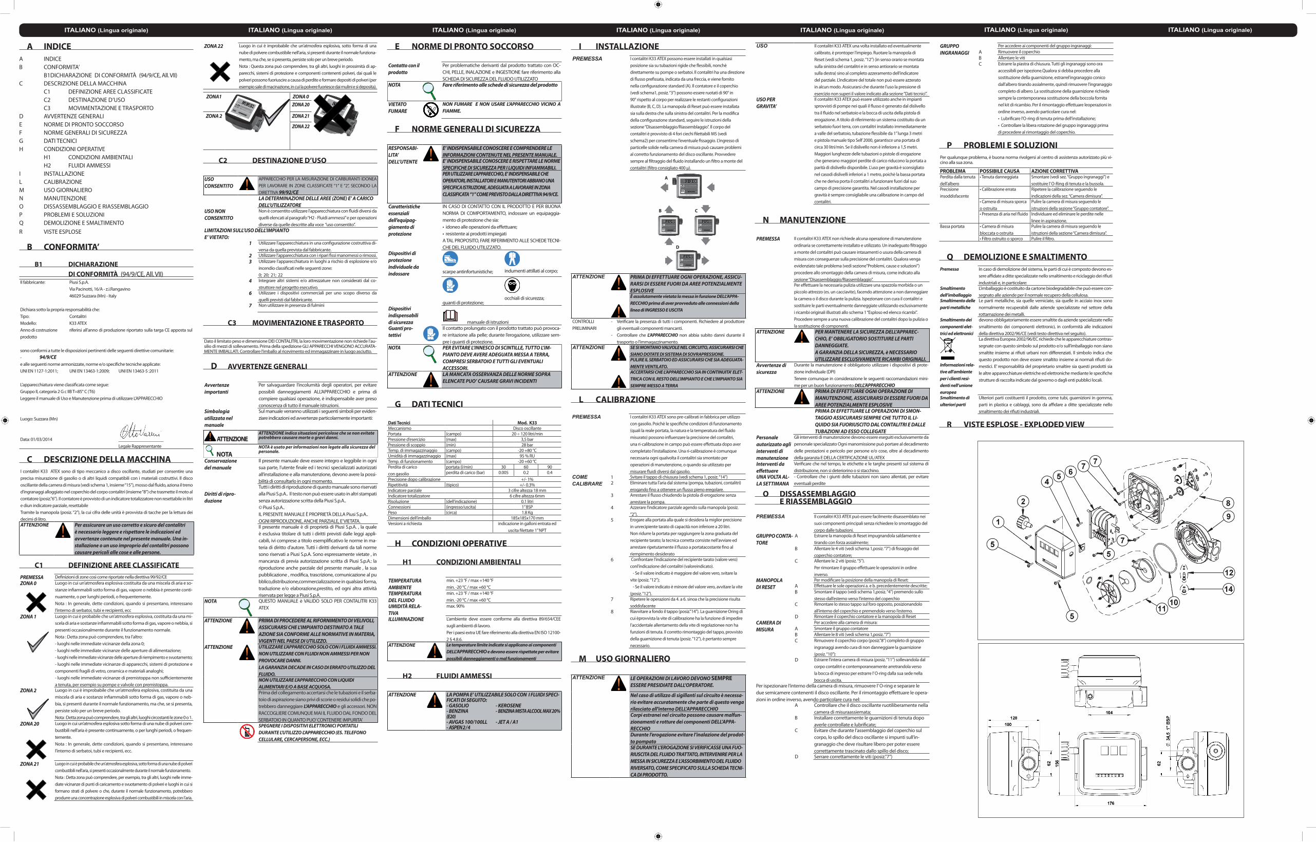
O DISSASSEMBLAGGIO E RIASSEMBLAGGIO
PREMESSA Il contalitri K33 ATEX può essere facilmente disassemblato nei suoi componenti principali senza richiedere lo smontaggio del corpo dalle tubazioni.
GRUPPO CONTA-TORE
A Estrarre la manopola di Reset impugnandola saldamente e tirando con forza assialmente;
B Allentare le 4 viti (vedi schema 1,posiz. “7”) di fissaggio del coperchio contatore;
C Allentare le 2 viti (posiz. “5”). Per rimontare il gruppo effettuare le operazioni in ordine inverso.
MANOPOLA DI RESET
Per modificare la posizione della manopola di Reset:A Effettuare le sole operazioni a. e b. precedentemente descritte;B Smontare il tappo (vedi schema 1,posiz. “4”) premendo sullo
stesso dall’esterno verso l’interno del coperchioC Rimontare lo stesso tappo sul foro opposto, posizionandolo
all’interno del coperchio e premendolo verso l’esterno.D Rimontare il coperchio contatore e la manopola di Reset
CAMERA DI MISURA
Per accedere alla camera di misura:A Smontare il gruppo contatoreB Allentare le 8 viti (vedi schema 1,posiz. “7”)C Rimuovere il coperchio corpo (posiz.”8”) completo di gruppo
ingranaggi avendo cura di non danneggiare la guarnizione (posiz. “10”):
D Estrarre l’intera camera di misura (posiz. “11”) sollevandola dal corpo contalitri e contemporaneamente arretrandola verso la bocca di ingresso per estrarre l’ O-ring dalla sua sede nella bocca di uscita.
Per ispezionare l’interno della camera di misura, rimuovere l’ O-ring e separare le due semicamere contenenti il disco oscillante. Per il rimontaggio effettuare le opera-zioni in ordine inverso, avendo particolare cura nel:
A Controllare che il disco oscillante ruotiliberamente nella camera di misuraassiemata;
B Installare correttamente le guarnizioni di tenuta dopo averle controllate e lubrificate;
C Evitare che durante l’assemblaggio del coperchio sul corpo, lo spillo del disco oscillante si impunti sull’in-granaggio che deve risultare libero per poter essere correttamente trascinato dallo spillo del disco;
D Serrare correttamente le viti (posiz.”7”)
GRUPPO INGRANAGGI
Per accedere ai componenti del gruppo ingranaggi:A Rimuovere il coperchioB Allentare le vitiC Estrarre la piastra di chiusura. Tutti gli ingranaggi sono ora
accessibili per ispezione.Qualora si debba procedere alla sostituzione della guarnizione, estrarrel’ingranaggio conico dall’albero tirando assialmente, quindi rimuovere l’ingranaggio completo di albero. La sostituzione della guarnizione richiede sempre la contemporanea sostituzione della boccola fornita nel kit di ricambio. Per il rimontaggio effettuare leoperazioni in ordine inverso, avendo particolare cura nel:• Lubrificare l’O-ring di tenuta prima dell’installazione;• Controllare la libera rotazione del gruppo ingranaggi prima di procedere al rimontaggio del coperchio.
P PROBLEMI E SOLUZIONIPer qualunque problema, è buona norma rivolgersi al centro di assistenza autorizzato più vi-cino alla sua zona.
PROBLEMA POSSIBILE CAUSA AZIONE CORRETTIVAPerdita dalla tenuta dell’albero
• Tenuta danneggiata Smontare (vedi sez. “Gruppo ingranaggi”) e sostituire l’ O-Ring di tenuta e la bussola.
Precisione insoddisfacente
• Calibrazione errata Ripetere la calibrazione seguendo le indicazioni della sez. “Camera dimisura”.
• Camera di misura sporca o ostruita
Pulire la camera di misura seguendo le istruzioni della sezione “Gruppo contatore”.
• Presenza di aria nel fluido Individuare ed eliminare le perdite nelle linee in aspirazione.
Bassa portata • Camera di misura bloccata o ostruita
Pulire la camera di misura seguendo le istruzioni della sezione “Camera dimisura”.
• Filtro ostruito o sporco Pulire il filtro.
Q DEMOLIZIONE E SMALTIMENTOPremessa In caso di demolizione del sistema, le parti di cui è composto devono es-
sere affidate a ditte specializzate nello smaltimento e riciclaggio dei rifiuti industriali e, in particolare:
Smaltimento dell’imballaggio
L’imballaggio è costituito da cartone biodegradabile che può essere con-segnato alle aziende per il normale recupero della cellulosa.
Smaltimento delle parti metalliche
Le parti metalliche, sia quelle verniciate, sia quelle in acciaio inox sono normalmente recuperabili dalle aziende specializzate nel settore della rottamazione dei metalli.
Smaltimento dei componenti elet-trici ed elettronici
devono obbligatoriamente essere smaltite da aziende specializzate nello smaltimento dei componenti elettronici, in conformità alle indicazioni della direttiva 2002/96/CE (vedi testo direttiva nel seguito).
Informazioni rela-tive all’ambiente per i clienti resi-denti nell’unione europea
La direttiva Europea 2002/96/EC richiede che le apparecchiature contras-segnate con questo simbolo sul prodotto e/o sull’imballaggio non siano smaltite insieme ai rifiuti urbani non differenziati. Il simbolo indica che questo prodotto non deve essere smaltito insieme ai normali rifiuti do-mestici. E’ responsabilità del proprietario smaltire sia questi prodotti sia le altre apparecchiature elettriche ed elettroniche mediante le specifiche strutture di raccolta indicate dal governo o dagli enti pubblici locali.
Smaltimento di ulteriori parti
Ulteriori parti costituenti il prodotto, come tubi, guarnizioni in gomma, parti in plastica e cablaggi, sono da affidare a ditte specializzate nello smaltimento dei rifiuti industriali.
R VISTE ESPLOSE - EXPLODED VIEW