english measuring instruments edition - …dl.mitutoyo.eu/...measuring_instruments_gb_small.pdf ·...
TRANSCRIPT

HANDHELD MEASURING INSTRUMENTS
A guide to proper use, maintenance and care
ENG
LISH EDITION
PRE1436


01
Handheld Measuring Instruments
Contents
Introduction 02
All Instruments 03
Digital Instruments 08
Outside Micrometers 12
3-Point (line) Internal Micrometers 16
2-Point Internal Measuring Instruments 18
Calipers 22
Height Gauges 24
Indicators 26
Dial Test Indicators 28
Depth Measuring Instruments 30
Auxiliary Equipment Comparator Stands 34
Gauge Blocks 36
WEEE Disposal of Batteries and Measuring Instruments 40
Notes 42

02
Introduction
High-quality handheld measuring devices are among the most important instruments – both in shopfloor surroundings as well as in laboratories and quality management departments. They are simple to operate and deliver precise and easy to read results.
Although they boast robust design – some models even an IP class – and long life expectancy they require proper treatment and care.
This booklet explains the correct care and maintenance necessary to ensure reliable results and a long lifetime of your handheld length measuring instruments.

03
Handheld Measuring Instruments
All Instruments
Before Use
ü Make sure type, measuring range, graduation – respectively digital step – and other specifications of the measuring instrument are appropriate for your application.
ü According to EN ISO 1, the reference temperature for length measurement is 20°C. At other temperatures, according to temperature requirements, countermeasures such as compensation become necessary.
ü Remove dust or dirt from the measuring instrument, especially from the measuring surfaces.
ü To clean the instrument, use a soft cloth soaked in a diluted neutral detergent. Do not use any organic solvent (thinner, benzine etc.). These might damage the instrument.
ü To prevent rust, wipe the moveable parts with a cloth moistened with anti-corrosion oil.
Application of a point jaw caliper

04
All Instruments
ü Check to see whether the moveable parts move smoothly without any jamming or unevenness by moving it all the way through its range.
ü Do not disassemble or modify the measuring instrument unless you have a profound knowledge.
ü Set the zero point or reference point before starting measurement. That means bring the measuring surfaces close together (e.g. outside micrometer 0-25 mm) or use an appropriate calibrated master gauge.
ü Reference setting and measuring should be carried out under as similar conditions as possible in order to minimise measurement errors.
Reference point setting with a gauge block
Zero setting with a 10 mm ceramic gauge block if the workpiece nominal is 10 mm

05
Handheld Measuring Instruments
Steel Aluminium Cast Iron Copper Ceramic BrassThermal Conductivity
l [W/(m · K)]47-58 appr. 200 appr. 58 appr. 384 appr. 2,9 appr. 113
During Use
ü Do not apply excessive force to the measuring instrument.
ü Make sure to apply constant measuring force during measurement e.g. by using the constant force device of an outside micrometer.
ü Do not use the measuring instrument for other applications than indicated by the specification (e.g. only perform measurement within the measuring range).
ü Perform the measurement in a stable and comfortable measuring position.
ü Leave the measuring instrument and the workpiece in the ambient room temperature long enough to adapt to the environment temperature. The ability of a material to conduct heat is specified by the thermal conductivity l [W/(m · K)]. Thermal conductivity is a matter constant. The higher the value, the higher the thermal transfer in relation to time.
Ratched thimble micrometers ensure constant and reliable measuring force of 5-10 N.

06
All Instruments
ü For analog instruments read the scale graduations from directly above the scale to avoid parallax error.
Fiducial lineSleeve
Thimble
ü The temperature of measuring tools rises when held in a bare hand. Perform the measurement as fast as possible or protect the instrument against body heat e.g. by using heat-insulating plates or wearing gloves.
ü If using the instrument in long measuring sessions, regularly check (and if necessary adjust) the zero point or reference point.
ü If the instrument is damaged due to being dropped or struck hard do not use it before checking its function and accuracy.
ü Whenever changing the instrument's configuration, like replacing exchangeable contact points, extension rods or any other parts, repeat reference setting.
Outside micrometer with heat-insulating plates.
Outside micrometer standard type.
3-point internal micrometers with exchangeable measuring heads require new reference setting after an exchange of the measuring head.

07
Handheld Measuring Instruments
After Use
ü Check the measuring instrument for damage. Repair or replace if necessary. Clean the instrument.
ü If the instrument was used at places contaminated by soluble cutting oil, perform rust prevention treatment after cleaning.
ü Store the instrument in a room free of excessive heat and moisture. Protect it from dust and oil mist.
ü Before storing the instrument for a long time, apply anti-corrosive coating for rust prevention.
ü Do not expose measuring instruments to direct sunlight.
ü Store measuring instruments in a case.
08
Digital Instruments
Before Use
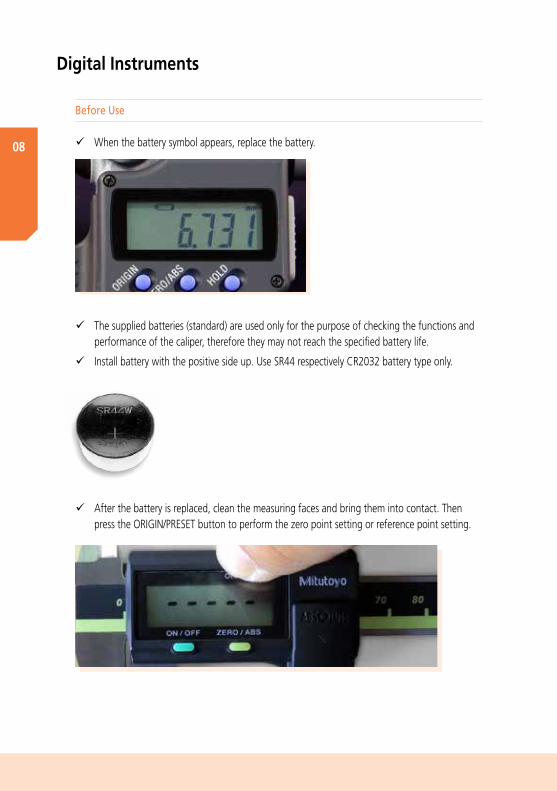
ü When the battery symbol appears, replace the battery.
ü The supplied batteries (standard) are used only for the purpose of checking the functions and performance of the caliper, therefore they may not reach the specified battery life.
ü Install battery with the positive side up. Use SR44 respectively CR2032 battery type only.
ü After the battery is replaced, clean the measuring faces and bring them into contact. Then press the ORIGIN/PRESET button to perform the zero point setting or reference point setting.

09
Handheld Measuring Instruments
ü When tightening the output connector cover and battery cap screws, make sure not to squeeze the rubber seal with the cap or cover.
ü Do not use electric pens to mark the measuring instrument. These may damage the internal circuitry. Any other types of voltage loads should also be avoided.
During Use
ü If any error occurs or the count is displayed abnormally, remove and reinstall the battery.
ü The operating temperature is between 5°C and 40°C. The electronic components of digital tools are designed to ensure operation within this temperature range. However, reference temperature for accuracy specification is 20°C, conforming to EN ISO1.
ü The maximum temperature gradient is 1,5 °C/min. Significant changes in the ambient temperature not only affect the measuring accuracy. The resulting condensation can damage digital tools, compromise sensor detection and cause corrosion.
ü The relative air humidity must be below 80%. To avoid condensation do not use measuring tools in high relative humidity at length in order to avoid condensation (which compromises sensor detection). It can also cause the parts made from organic materials to swell and have adverse effects to the electric circuits. However, if the ambient air is too dry, static electricity may cause malfunctions.
ü Magnetic or electromagnetic fields generated by a magnetic chuck or a demagnetiser do not state a problem. A demagnetiser can be used on measuring tools. Remove the battery and use the lowest level of the demagnetisation instrument for a short time only.
ü Low pressure (< 1,33322 Pa) can damage the LCD and cause the battery to leak.
Rubber seal to protect the battery housing respectively output connector against ingress.

10
Digital Instruments
ü Radioactive radiation will cause deterioration of the ICs and other components.
ü The digital instruments have no explosion prevention and protection.
ü High IP grades (e.g. IP67) should not be misunderstood as a license to careless or even negligent treatment of the equipment. Coolant fluid will eventually cause damage if the instruments are not treated with the proper care throughout their service life.
ü If the data output and a dedicated cable is used, avoid tensile stress, excessive bending and buckling of the connected cable.
Avoid abnormal cable guidance and tensile stress.

11
Handheld Measuring Instruments
ü A foot switch eases data transfer from a Digimatic handheld measuring instrument to a PC or a data collecting device, minimises operator fatigue and extends the data switch's lifetime.
After Use
ü The storage temperature must be between -10°C and 60°C. Parts made of different materials are bonded in digital instruments. Under excessively severe temperature conditions, they may be damaged due to the difference in thermal expansion coefficient between them.
ü Do not expose digital measuring instruments to ultraviolet radiation at length. They deteriorate the plastic parts and the LCD (liquid crystal display).
ü If the measuring instrument is not in use for more than 3 months, remove the battery from the instrument. The battery might leak and cause damage.

12
Outside Micrometer
Measuring Faces
Frame
Anvil
Spindle
ThimbleFast Drive (Speeder)
Sleeve
Spindle Clamp
Thermal Insulation Plate
Data Output
Before Use
ü Clamp a sheet of lint-free paper between anvil and spindle, as if measuring its thickness. Slowly draw it away to remove dust or dirt from the measuring faces.
ü Especially when the measuring range exceeds 300 mm, adjust reference point (preset value). In this process – due to frame deflection – the micrometer should be in the same position it will be in when measuring.

13
Handheld Measuring Instruments
During Use
ü Do not retract the spindle too far past the upper limit of the measuring range. This can damage some types of digital micrometer.
ü Do not spin the micrometer violently.
Outside micrometer 0-25 mm.

14
Outside Micrometer
Make contact slowly.
After Use
ü Release the spindle clamp, separate the measuring faces by approximately 0.2 to 2 mm, and then store the instrument in a appropriate case.
Unlocked
ü Always use the ratchet stop, ratchet thimble or friction thimble when measuring.
ü Slowly bring the measuring faces into contact and rotate the ratchet stop several times (1.5 to 2 turns) to apply constant pressure. Excessive force may affect the measurement accuracy.
ü The spindle of the Mitutoyo QuantuMike outside micrometer advances 2 mm in one rotation. Its spindle feeds rapidly, so be careful not to feed the spindle too fast during measurement or zero point adjustment, to prevent the spindle from touching the measurement surface.
ü When mounting the micrometer on a stand, ensure that the micrometer frame is clamped at the center. Do not clamp it too tightly.
QuantuMike with 2 mm spindle pitch. Micrometer stand

15
Handheld Measuring Instruments

16
3-Point (line) Internal Micrometer
Ratchet Stop
Thimble
Scale
Measuring Head
Contact Line
Display
Contact Point for Extensions
SleeveData Output
Measuring Pin
Before Use
ü Perform the initial setting using the calibrated master gauge.
300 mm setting ring

During Use
ü Retracting the spindle of a digital 3-point internal micrometer too far past the upper limit of the measuring range will damage the internal micrometer. If resistance is felt do not retract the spindle any further.
ü To apply measuring force, bring the measuring face into light contact with the workpiece and hold there. Then operate the ratchet 5 or 6 times (2 to 3 turns) to apply constant force.
17
Handheld Measuring Instruments
After Use
ü See all instruments, respectively digital instruments.
ü If measuring using only a part of the measuring surface (contact line), make sure to set the reference point at the same position of the surface. Follow the general guideline: Adjust in the same manner you measure.
ü Note that if the measuring head is replaced or an extension is used, the accuracy specification is no longer guaranteed unless the initial setting is repeated.
MeasuringSetup

18
2-Point Internal Measuring Instruments
Fix Anvil
Measuring Head
Moveable Contact Point
Guide Plate
Anvil Contact Point
Tube
Thermally Insulated Grip
Clamping Device
Protection Cover
Indicating Device
Slit Measuring Head
Before Use
ü Securely tighten the clamping device to lock the gauge in position. If the gauge still moves, clean the gauge stem and the clamping device.
ü To perform reference setting, a calibrated setting ring, respectively a bore gauge checker with gauge blocks, is recommended.
Bore Gauge Checker

19
Handheld Measuring Instruments
pre-span ≈ 0,1 mm
post-span ≈ 0,1 mm
Midpoint of the measuring range
0,8 mm 0,8 mm
Measuring span = 1,6 mm
Nominal span = 2 mm
Anvil
Washer
Main Unit
Main Unit 35-60 mm
Anvil 50 mm
Washer 1 mm, 3 mm
ü Set the zero point (midpoint of the measuring range) of the bore gauge, in 0,5 mm increments, to the appropriate median of the bore diameter range. Example: Nominal value of the hole: 54 mm
During Use
ü To insert the bore gauge into the hole to be measured or a setting ring (for reference point setting), tilt the handle so that the guides enter first, followed by the anvil, as shown below.

2-Point Inside Measuring Instruments
Setup:For Bore Gauges, the differential measuring method means that the indicator is set to zero by using a reference gauge with a dedicated measurand. For measuring the workpiece, the difference to the reference gauge is shown on the indicator gauge.
A bigger diameter effects a pointer deflection in negative direction (counter clockwise).
A smaller diameter causes a pointer deflection in positive direction (clockwise).
Cleaning parts
ü Note the correlation between the directions of the contact point displacement and indicator’s pointer rotation. The clockwise rotation of the pointer from the reference point indicates that the measured dimension is smaller than the set value. Counter-clockwise pointer rotation from the reference point indicates that the measured dimension is larger than the set value.20
After Use
ü Store the bore gauge with the indicator removed.
ü If contamination is suspected inside the measuring or the sliding section, clean the inside of the head with a diluted neutral detergent after disassembling using snap-ring pliers. After cleaning, dry completely and apply a film of micrometer oil to the contact point and the driver pin.

21
Handheld Measuring Instruments

22
Measuring Faces for Internal Measurement
Vernier Scale Inch
Fixed Jaw
Measuring Faces for External Measurement
Sliding Jaw
Vernier Scale Metric
Clamping Device
Slider Beam Main Scale Depth Measuring Rod
Measuring Faces for Depth Measurements
Calipers
Before Use
ü Close the measuring faces after cleaning and check the following: Outside measuring faces are in good condition if no light can be seen between them when they are held against a light source. If the faces show contamination or burrs they will not close properly on their full length and light will be seen between them. Inside measuring faces are in good condition if only little light can be seen between them when they are held against a light source.
During Use
ü Make sure to apply constant force during measurement and measure the workpiece as close to the scale as possible.

23
Handheld Measuring Instruments
After Use
ü Open the outside measuring jaws by approximately 0.2 to 2 mm, leave the locking screw untightened, and then store the instrument in a proper case.
ü Do not measure an object with the measuring faces tilted.
ü The knife edges for hole measurement should not be used for holes smaller than appr. 3 mm in diameter. Otherwise a relatively big measurement error caused by the inside measuring jaws will occur and have to be compensated.

24
Before Use
ü Set the stylus as close to the main beam as possible.
ü Clean beams, instrument reference base, stylus mounting surface as well as the granite surface plate on which the height gauge will be used.
ü When carrying the instrument, hold it with one hand on the top and the other on the base.
Height Gauges
Probe Extension
Measuring Face
Instrument Reference Base
Beam
Guiding Face
Locking Device
Main Scale
Measuring and Scribing Stylus
Vernier Scale
Fine-adjustment Device
Slider
Instrument Base
Fixing Device

25
Handheld Measuring Instruments
During Use
ü Rotate the feed wheel slowly when applying a constant measuring force. Coarse feed or fine feed (if available) can be selected by pulling or pushing the handle of the slider feed wheel.
Dust cover
After Use
ü When the height gauge will not be used for some time leave the scriber unclamped and just above, but not touching, the surface plate. This is to avoid injury by accidental contact with the scriber tip.
ü Be especially careful not to let the scriber protrude over the edge of the surface plate at any time.
ü If the instrument will not be used for a long time, cover the unit with the supplied dust cover.
Excessive downwards force lifting the base from the plate
Coarse feedTo use coarse feed push the handle in and rotate the whole wheel.
Fine feedTo use fine feed, pull the handle out and rotate its sleeve.

26
Indicators
Pointer
BezelDial
Revolution Counting Device
Limit Indicator
Bezel Clamp
Dial Cover
Stem
Plunger (spindle)
Contact Element
Operation Buttons
Display
Protection CapData Output
Scale
Before Use
ü When setting the zero point, retract the plunger by at least 0.2 mm from the rest position.
ü To avoid measuring error due to non-perpendicular positioning (plunger to table), ensure that the plunger is accurately aligned with the intended direction of measurement. Also note that unevenness of the reference surface may cause measuring errors.
0.2m
m
Positioning error

27
Handheld Measuring Instruments
ü Use a holding fixture that will not deflect significantly during normal use.
ü If the pointer and revolution counter are significantly out of position at the rest point (where the spindle is fully extended), the device may suffer mechanical demage.
After Use
ü See all instruments, respectively digital instruments.
ü Use the contact point that fits the application best.
During Use
ü Do not move the plunger rapidly or apply force in transverse direction, otherwise operation and accuracy may be adversely affected.
ü Use a lifting lever, a spindle lifting cable or any other appropriate device to release the plunger from the workpiece.
Application with spindle lifting cable.

28
Dial Test Indicators
Pointer
Housing
Friction or Ratchet Device
Magnetic Stand
Scale
Bezel
Dial
Stylus
Stylus Tip
Before Use
ü Be sure to use the stylus with standard length matching the indicator model, otherwise a large measuring error may be the result.
ü Use a holding fixture that will not deflect significantly during normal use.

29
Handheld Measuring Instruments
After Use
ü See all instruments, respectively digital instruments.
ü A Dial Test Indicator’s scale factor depends on the angle between the directions of movement of stylus and workpiece. In practice, to avoid significant error, if the angle θ is kept less than 10° during measurement, then the effect can be ignored. If this angle cannot be kept small, the dial reading has to be multiplied by a factor to compensate this so-called cosine effect.
ü When measuring a rotating or moving workpiece or when moving the dial test indicator, ensure that it rotates or moves away from the contact point.
Direction of workpiece movementDirection of stylus movement
Direction of workpiece movement
Direction of stylus movement
Measurement direction

30
Depth Measuring Instruments
Measuring Base
Measuring Face
Slider
Locking Screw
Beam Main Scale
Fine-Adjustment Device
Vernier Scale Metric
Measuring Base
Measuring Rod
Thimble
Measuring Faces
Fast Drive (Speeder)
Sleeve

31
Handheld Measuring Instruments
Before Use
ü Slowly bring the movable measuring face (rod/beam) into contact while pressing the fixed measuring face (base) against a flatness-assured surface such as a precision surface plate. Then setup the reference point, if necessary. Use gauge blocks to check the setting of depth micrometers if the reference point is over 25 mm and of indicator depth gauges with extension rods.
ü When changing the rods of depth micrometers, remove dust or dirt from the contacting surfaces on the rod collar and spindle end.
Exchangeable rods
32
Depth Measuring Instruments
After Use
ü See all instruments, respectively digital instruments.
During Use
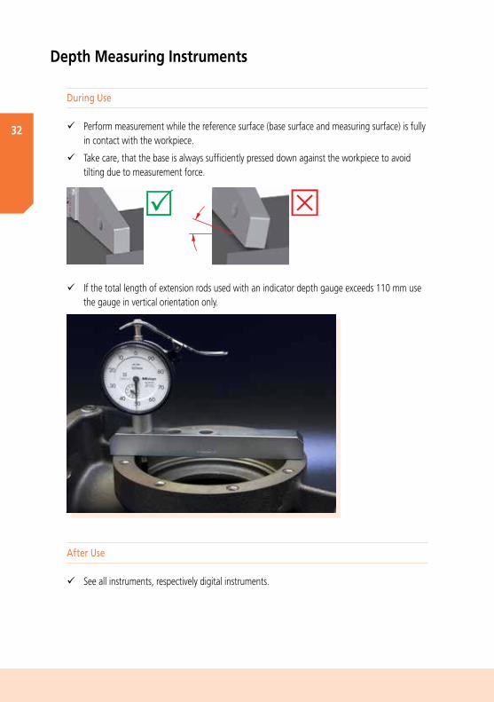
ü Perform measurement while the reference surface (base surface and measuring surface) is fully in contact with the workpiece.
ü Take care, that the base is always sufficiently pressed down against the workpiece to avoid tilting due to measurement force.
ü If the total length of extension rods used with an indicator depth gauge exceeds 110 mm use the gauge in vertical orientation only.

33
Handheld Measuring Instruments

34
Auxiliary Equipment Comparator Stands
Before Use
ü Clean the worktable using a dry cloth or a cloth moistened with alcohol.
ü Make sure to hold the bracket firmly when moving it up or down.
ü Mount the indicator in the stem mounting hole and tighten the clamp screw. Clamp the indicator firmly. However, the plunger of the indicator must still move smoothly.
ü After adjusting the measuring position, tighten the slider clamp before starting measurement.
ü For reference point adjustment, it is recommended to use a gauge block or a master workpiece.
Holder
Base
Column
Slider Clamp
Clamp Screw for Slit Bush(Stem Bush)
Worktable
Stem Bush20 mm -> 8 mm
Stem Bush3/8“ / 9,53 mm -> 8 mm
Fine Feed Knob
Reference point setting with a 50 mm Gauge Block.

35
Handheld Measuring Instruments
After Use
ü See all instruments, respectively digital instruments.
During Use
ü Especially for high-accuracy measurements move the plunger of the indicator upwards and downwards using any spindle lifting device such as a spindle lifting cable or a spindle lifting lever to avoid excessive force when changing the measurement equipment.
ü To finely adjust the measuring position, use the fine feed knob, if available.
ü Avoid repeated touching of the worktable with the contact point, or dropping the contact point abruptly.
ü In the case of scratches on the worktable surface, remove any burrs with a lightly abrasive stone before continuing measurement.
Lifting cable Lifting lever Lifting knob
Lifting handle

36
Gauge Blocks
Before Use
ü To obtain maximum benefit from the extreme accuracy of gauge blocks, use them in a thermally stable environment.
ü Wipe off the oil film from the gauge blocks using a soft cloth and petroleum ether.
ü After wiping, the surfaces are cleaned with a cosmetic brush rinsed with petroleum ether and then blown clean with bellows.
ü Never use alcohol or benzine for cleaning; benzine contains impurities and alcohol always contains aqueous components which may cause corrosion.
ü Best-suited for wiping gauge blocks are microfibre cloths.
ü Check the cleaned gauge blocks for rust and scratches.
ü If there are burrs on the measuring surface remove them carefully using a special Ceraston for gauge blocks. Move the dry gauge block over the Ceraston with very little pressure.
Left Hand Measuring Face
Marked Measuring Face
Unmarked Measuring Face
Side Faces
Marked Side Face
Right Hand Measuring Face
37
Handheld Measuring Instruments
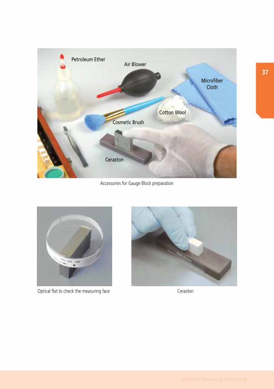
Air BlowerPetroleum Ether
Cosmetic Brush
Cotton Wool
Microfiber Cloth
Ceraston
Accessories for Gauge Block preparation
Optical flat to check the measuring face Ceraston
38
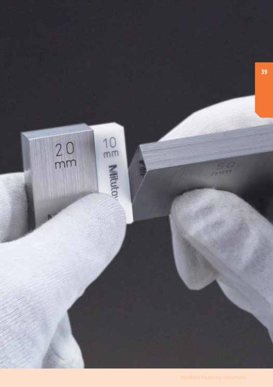
During Use
ü Wringing should always be performed in a clean place on a soft pad – if gauge blocks slip out of your hand, they will not be damaged.
ü In case the measuring surfaces are in good condition, but wringing is still difficult, you may wipe them with medical cotton wool – its oily components will provide a fine film, thus improving the grip of the measuring surfaces.
After Use
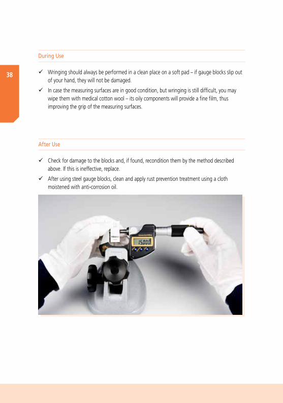
ü Check for damage to the blocks and, if found, recondition them by the method described above. If this is ineffective, replace.
ü After using steel gauge blocks, clean and apply rust prevention treatment using a cloth moistened with anti-corrosion oil.
39
Handheld Measuring Instruments

40
WEEE Disposal of Batteries and Measuring Instruments
Disposal of measuring equipment
ü Disposal of Old Electrical & Electronic Equipment (applicable in the European Union and other European countries with separate collection systems)
ü This symbol on the product or on its packaging indicates that this product shall not be treated as household waste. To reduce the environmental impact of WEEE (Waste Electrical and Electronic Equipment) and minimise the volume of WEEE entering landfills, please reuse and recycle.
ü For further information, please contact your local dealer distributor or your domestic Mitutoyo sales company.
Disposal of batteries
ü Batteries contain materials that can harm the environment when treated as conventional waste. On the other hand, most of these materials can be recycled, saving valuable resources. Therefore, for disposing of old batteries you are obliged to hand them to a certified battery collecting point.

41
Handheld Measuring Instruments

42
Notes

43
Handheld Measuring Instruments

44

MITUTOYO, DIGIMATIC and QUANTUMIKE are either registered trademarks or trademarks of Mitutoyo Corp. in Japan and/or other countries/regions. Other product, company and brand names mentioned herein are for identification purposes only and may be the trademarks of their respective holders.

Mitutoyo Europe GmbHBorsigstraße 8-10 41469 Neuss Germany
T +49 (0) 2137-102-0 F +49 (0) 2137-102-351
[email protected] www.mitutoyo.eu