engineers design and processing manual appendix
TRANSCRIPT
CITY OF OCEANSIDE
ENGINEERS DESIGN AND PROCESSING MANUAL
APPENDIX
CONSTRUCTION GUIDELINES AND
REQUIREMENTS
WATER SYSTEM TESTING REQUIREMENTS A) Chlorination and Bacteria Testing
1. Chlorination and bacteria testing will be accomplished by either a representative of the City Engineering Department or the Utilities Department. Arrange for all testing thru the Public Works Inspector.
2. Chlorine and bacteria testing will be according to AWWA requirements and
the following:
All new water lines will be disinfected with a minimum of 25 parts per million of chlorine. The chlorinated line will be allowed to set for a 24 hour period at which time there must be a minimum of 1O parts per million chlorine residual. If this residual is not met, the line will be flushed with potable water and rechlorinated to a minimum of 25 parts per million. It will again sit for 24 hours and the minimum of 10 parts per million chlorine residual must be achieved. Once this test is passed, the line will be flushed with potable water will sit for a minimum of four hours after which a sample of water will be taken for bacteria testing purposes. The sample will be taken by a representative of the City Engineering Department and delivered to the City's laboratory. The results of the E Coli bacteria test will be know after 48 hours. The costs for the bacteria analysis will be billed to the developer that installed the water line. At no time will a line that has not been tested and found free of contamination be connected to the City's water system. The practice of testing against a valve tied to the City's system is not authorized in the City of Oceanside. All water used for testing and flushing must be metered and the developer will be charged for the water at the prevailing rate.
A minimum of four working days is required for these tests. Additional time
will be required where tests fail.
3. Failing Bacteria Tests will require the following:
a) First Failure: Flushing and re-test for bacteria.
b) Subsequent Failures: Flushing, re-chlorinating the system, flushing the chlorine and re-test for bacteria.
4. Chlorine tablets will not be placed in direct contact with the PVC pipe at any
time.
5. Contact the Public Works Inspector prior to disposing of the chlorinated water to establish an approved means of disposal.
2/13/91 153 Revised 8/26/92

B) Hydrostatic Testing
1. Testing against valves is not authorized. End caps with tapped risers for filling or air release with an appropriate size concrete thrust block will be installed to test against.
2. Pipe Manufacturer's recommendations for filling and testing shall be
followed.
3. The Hydrostatic test will be observed and verified by a representative of the City Engineering Department. Arrange for the testing thru the Public Works Inspector.
4. All water systems will be pre-tested to insure they will pass a 2 hour test
prior to calling for the Public Works Inspector.
5. The developer or contractor shall furnish all materials including water, pumps, meters, equipment, bracing, connections, labor and expense required for testing of water mains. He shall be responsible for the results of any failure under test which are attributable to defective material and/or workmanship furnished by him or to his negligence or improper conduct of the test.
6. Each water main shall be hydrostatically tested by the contractor in the
presence of the Engineer after all pipe and appurtenances have been installed, all anchors, thrust blocks and encasements have been placed and have attained sufficient strength, and the required select and/or other specified backfill has been compacted and certified by the Soils Engineer.
7. The pipeline shall be tested as directed by the Engineering Representative.
The entire pipeline shall successfully meet the requirements specified herein before any portion will be accepted. The test shall be made by placing end caps at the ends of the pipe and filling the pipeline with water in such a manner as to prevent air pockets. After the line has been completely filled, it shall be allowed to stand under pressure to permit escape of air pockets and to examine valves and connections for leaks.
8. The test pump and gauge shall be connected to the water main at a location
other than the highest point in the line, in order to allow release of air from the high point. Means shall be provided for accurately measuring the quantity of water pumped into the pipe during or immediately after the test period in order to maintain or restore the initial test pressure. All pipe, fittings, valves, hydrants, services and appurtenances shall be subjected to the hydrostatic test and irrespective of the measured quantity of leakage; all
2/13/91 154 Revised 8/26/92
detectable leaks shall be repaired by the contractor unless otherwise specified herein.
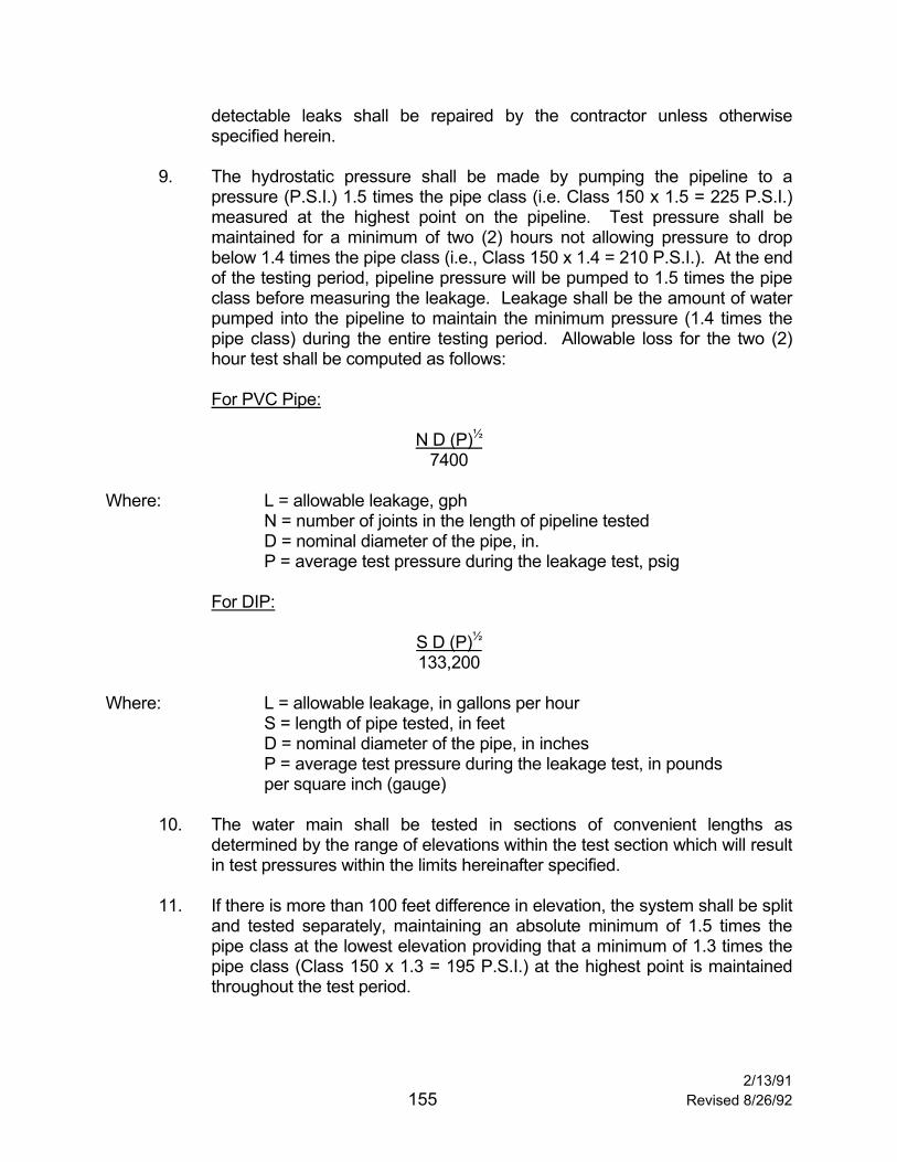
9. The hydrostatic pressure shall be made by pumping the pipeline to a
pressure (P.S.I.) 1.5 times the pipe class (i.e. Class 150 x 1.5 = 225 P.S.I.) measured at the highest point on the pipeline. Test pressure shall be maintained for a minimum of two (2) hours not allowing pressure to drop below 1.4 times the pipe class (i.e., Class 150 x 1.4 = 210 P.S.I.). At the end of the testing period, pipeline pressure will be pumped to 1.5 times the pipe class before measuring the leakage. Leakage shall be the amount of water pumped into the pipeline to maintain the minimum pressure (1.4 times the pipe class) during the entire testing period. Allowable loss for the two (2) hour test shall be computed as follows:
For PVC Pipe:
N D (P)½
7400 Where: L = allowable leakage, gph N = number of joints in the length of pipeline tested D = nominal diameter of the pipe, in. P = average test pressure during the leakage test, psig For DIP:
S D (P)½ 133,200
Where: L = allowable leakage, in gallons per hour S = length of pipe tested, in feet D = nominal diameter of the pipe, in inches P = average test pressure during the leakage test, in pounds per square inch (gauge)
10. The water main shall be tested in sections of convenient lengths as
determined by the range of elevations within the test section which will result in test pressures within the limits hereinafter specified.
11. If there is more than 100 feet difference in elevation, the system shall be split
and tested separately, maintaining an absolute minimum of 1.5 times the pipe class at the lowest elevation providing that a minimum of 1.3 times the pipe class (Class 150 x 1.3 = 195 P.S.I.) at the highest point is maintained throughout the test period.
2/13/91 155 Revised 8/26/92

12. All water mains shall be tested for the time period and at the pressure
specified. Any detectable leak shall be repaired. After all leaks have been repaired, the test shall be repeated until the section tested has met the above requirements.
2/13/91 156 Revised 8/26/92

BEDDING AND BACKFILL
TESTING SPECIFICATIONS NEUTRAL BACKFILL AND NATIVE BACKFILL MATERIAL Testing and quality control of neutral backfill material and native backfill material has become more of an issue due to availability. Whenever there is a question of the suitability of the backfill material, a correction notice requesting testing of the material for conformance to the following requirements shall be written. Where "Neutral" material is specified for corrosion to ferrous metal fitting, the following specifications, as a minimum, shall be met. Sand Equivalent 30 Minimum pH 6.5 - 8.5 Resistivity 1500 - 50,000 ohm-cm Sulfate (optional) 2000 ppm or Less Where "Sand" is specified, a sieve analysis shall be required if material gradation is questioned regarding excessive fines or oversize material. The minimum requirements for a "Sand" shall be that the material has 100% passing the 3/8 inch sieve and less than 6% passing the 200 sieve. Where "Native" material is specified as an option for backfill material, a sieve analysis and sand equivalent shall be required. The material shall have a minimum S.E. of 30 and the sieve analysis shall conform to the disintegrated granite gradation from the Green Book Section. 400 2.3.2. Sieve Size Percent Passing 1" 90-100 No. 4 50-100 No. 30 25- 55 No. 200 5- 18 Prior to placement of material requiring certification a qualified laboratory will test and the results will be submitted to the City of Oceanside for approval. If approved, continuous or random testing for conformance will be required.
2/13/91 157 Revised 8/26/92

BACKFILL/TRENCH
TESTING REQUIREMENTS The following are the minimum compaction testing requirements for all developments. Additional tests may be required at the discretion of the inspector. 1. Test every fifth sewer lateral (Elev. at 2' intervals F.G.). 2. Test sewer main between each manhole (alternate tests between -2 intervals feet
below F.G.). 3. Test storm drain backfill between each structure or at 200 foot intervals along side
of pipe and at an elevation of -2 to -4.5 feet below F.G. when pipe is placed in a trench where top of culvert is 3 feet or more below ground level.
4. Test structure backfill around all drainage structures (1 test per structure -2 to -5
feet below F.G.). 5. Test every sixth water lateral (-2 to 3 feet below F.G.). 6. Test water main every block (-2 to 3 feet below F.G.). 7. Subgrade and base compaction tests to be taken at the rate of test per block or
every 300 feet. 8. Test utility trench in joint trench at 300 foot intervals. 9. Test every fifth utility lateral in the same manner as main trench is tested. 10. Embankment test within proposed street right-of-way shall be taken in each fill
every two feet in vertical elevation and at 250 feet intervals along fill. Formal results of all tests taken, including failures, shall be forwarded to the City Engineer within ten days after the tests are taken. All failures shall require area recompaction and retesting as required by the City Engineer. All Utility Tests (including Sewer and Water) shall be formally submitted to the City Engineer prior to the construction of curbs gutters, base or paving. Design and control testing of Portland cement concrete and asphalt concrete will be requested as necessary during construction of the project by the City Engineer.
2/13/91 158 Revised 8/26/92

PRE-CONSTRUCTION REQUIREMENTS 1. Hours of Operation (515)(34): 7:00 am to 6:00 p.m. M-F; including equipment
warm-up.
Saturday Operation: Requires filing a permit by 2:30 p.m. on the preceding Thursday.
2. Developers Rep. or Supt: To be on site full time. 3. Mass Grading Daily Reports: City copies of daily reports to be kept on site in a two
inch notebook which is to be turned into the City with mass grading soils report. 4. Soil Engineer: To be present during all grading operations. 5. Field Changes: All changes in approved plans, soils reports, and specifications
must be submitted to the City, reviewed and approved prior to implementation in the field.
6. Construction Water: By permit only-no unprotected hoses in the street. 7. Clean & Grub: Maintain dust control. Provide haul routes for removal (see #9). No
grading within 100' of stockpiles. 8. Dust Control: Required during construction at all times. 9. Haul Routes: Permit required from Traffic Engineer. Provide map of hauling, begin
& end dates, and maximum number of trucks to be used. Street cleaning is required; See #12.
10. Traffic Control Plan: Permit required from Traffic Engineer prior to implementing
any traffic control. 11. Import & Export: Permit required from Traffic Engineer. 12. Debris in Streets: Forbidden by Vehicle code. Stop Notice issued for non-
compliance. Clean Up: Bonding will be required. 13. Protection of Adjoining: Developer's responsibility (read the section). No grading
on adjacent properties until an approved Permission to Grade letter is on file in Engineering.
2/13/91 159 Revised 8/26/92

14. Notice to Inspectors: 24 hours notice for ALL INSPECTIONS. Phone (760) 435-5081 and leave a message on the recorder.
15. Canyon Clean-out: 24 hours notice for inspectors; and written approval by Soils
Engineer or Geologist (not Technician) prior to inspection. Can be a field memo. 16. Key-ways & Benches: Same as number 15. 17. Sub Drain: Same as number 15. Method of construction approved by Engineering
prior to installation. Materials certification approved (see 18. Location surveyed as "As-Built" plans.
18. Materials Certification: A letter of certification from a Material Testing facility stating
compliance with specifications and test results for all road base, permeable materials, etc., shall be on file at the City prior to placement in the field.
19. Testing: Minimum 25%. Sandcone. Minimum 90% Compaction. 20% of density
test shall be taken within 3' of final slope and one (1) test within the outer 12" of the final slope, for every 5,000 square feet of slope area.
20. Fills of 10'. + or: Same as number 15. 21. Slopes: Overfill & Cut Back Debris fence on slopes above all traveled roadways. 22. Cover Critical Items in the Soils Report: By Soils Engineer, City Geotechnical
Consultant. (Settlement monumentation for surcharge areas). 23. Erosion Control: See Ordinance #82-43. 24. Emergency Telephone Numbers: Answering machine or service is NOT
ACCEPTABLE!!! 25. Before Building permits can be issued: (A) Final Soils report by Soil Engineer (B) Pad certification by Civil Engineer (C) Construction phasing plan by developer (D) Permanent fire protection in and approved 26. Interim Soils Report: Approved prior to beginning underground construction. 27. Slopes planted within 45 days of completing grading.
2/13/91 160 Revised 8/26/92
28. All items shown on the approved plans must be completed and "As-Built" plans approved prior to requesting bond release.
29. Structural section recommendations shall be submitted to City Engineer for
approval. 30. All drainage devices, slope planting and certifications complete and approved prior
to release for occupancy (See Release for Occupancy check list for additional requirements).
31. See attached AB73 Highlights for underground. OWNER CONTRACTOR ENGINEER OF WORK SOILS ENGINEER CITY INSPECTOR
2/13/91 161 Revised 8/26/92

OCCUPANCY REQUIREMENTS
Prior to the release of any buildings for occupancy by the Engineering Department, all construction activities, including but not limited to the following shall be complete. A. Public Improvements Completed Per Signed Improvement Plans. 1. Water System Complete All testing complete All valve cans raised All fire hydrants in, painted and fire flow tested 2. Sewer System Complete Per Plan All testing complete All manholes and cleanouts raised Sewer cleaned of construction material 3. Paving Complete Per Plan Striping, signs, barricades and reflectors Water test All Engineer's Certification in and approved clean (washed and swept) 4. Sidewalks Completed Per Plan (includes curb & gutter) All major repair complete All trip hazards eliminated Clean (washed and swept) Mail boxes installed Street signs installed 5. Street Lights Installed and 18-Month Energy Fees Paid (Public And Private) 6. Drainage Complete Per Precise Grading Plan Inspected and approved Engineer's Certification Clean drains 7. Monumentation In and Inspected 8. Landscaping Complete and Approved By Inspector
2/13/91 162 Revised 8/26/92

9. City Right-of-Way and Easement Areas To be maintained free and clear of structures prior to City acceptance. 10. All Certifications as Required, Accepted and On File with the City Engineer
11. Completion of All Necessary Construction According to the Approved Plans and Specifications
The Finish Grade Certifications shall indicate that all swales have been graded per plan (1% minimum), and the provisions of Section 1701 (a) [2] (a through f) of the City's Grading Ordinance have been met. The Finish Grade Certification letter shall also be accompanied by FEMA Elevation Certificate completed for each and every lot. The Elevation Certificates can be obtained through FEMA. Further information maybe obtained at the Engineering counter.
2/13/91 163 Revised 8/26/92
AB73 HIGHLIGHTS
Digging on private property as well as public property by a contractor now requires notification of Underground Service Alert.
Dig Alert numbers are valid for 14 calendar days; and must be revalidated if
excavation is to continue beyond the 14 day period.
The excavator must mark plainly, using white paint where he plans to dig or supply exact location information to USA.
A USA member (the owner of subsurface installations) must locate and mark the lines
clearly, using the appropriate color. During the course of the job if the original markings are no longer visible, the excavator is to re-contact USA. The member will then be informed that he is requested to re-locate and remark the lines within two working days.
The excavator must determine the exact location of marked underground facilities by
using hand tools before any power equipment is to be used.
Owners (of subsurface installations) and excavators are both subject to fines of up to $10,000 for negligently violating the new law.
Any owner or excavator who knowingly and willfully violates any of the law's provisions
is subject to fines of up to $50,000.
Action against a violator may be brought by the local (city, county, etc.) or state agency that issued the permit to excavate - as well as the Attorney General and the district attorney.
If an excavator doesn't comply by calling USA for Dig Alert number; or doesn't
properly expose the underground lines before using power equipment, the excavator is liable for any damage resulting from excavation.
Owners of underground lines who are not members of Underground Service Alert
forfeit their right to recover damages to their underground facilities by excavators.
The law does not apply to property owners who perform excavation work that doesn't require a permit.
2/13/91 164 Revised 8/26/92

CITY OF OCEANSIDE PAVEMENT DESIGN GUIDELINES STREET DESIGNATION
PRIME ARTERIAL
6-LANE MAJOR
4-LANE MAJOR
SECONDARY ARTERIAL
INDUSTRIAL/ COLLECTOR
LOCAL COLLECTOR
LOCAL STREET
CUL-DE-SAC (RESIDENTIAL)
PRIVATE (RESIDENTIAL)
ASPHALT THICKNESS (IN)
6 6 6 5 4 4 3 3 3
TRAFFIC INDEX 10 10 9 8 7 6 5 5 5
R-VALUE AGGREGATE BASE THICKNESS
(INCHES)
5 24.5 24.5 21.5 20.0 18.0 14.5 12.0 12.0 12.0
10 24.0 24.0 20.0 18.5 17.5 13.5 11.0 11.0 11.0
15 22.0 22.0 18.5 17.0 15.5 12.5 10.0 10.0 10.0
20 20.5 20.5 15.5 14.5 13.0 11.5 9.5 9.5 9.5
25 18.5 18.5 17.0 15.5 14.0 10.5 8.5 8.5 8.5
30 17.0 17.0 14.0 13.0 11.5 9.5 7.5 7.5 7.5
35 15.0 15.0 12.0 11.5 10.5 8.0 6.5 6.5 6.5
40 13.0 13.0 10.5 10.0 9.0 7.0 6.0* 6.0* 6.0*
45 12.0 12.0 9.0 8.5 8.0 6.0* - - - - - - - - -
50 10.0 10.0 7.5 7.0 7.0 - - - - - - - - - - - -
55 8.0* 8.0* 6.0* 6.0* 6.0* - - - - - - - - - - - -
165
NOTES: 1. * indicates minimum base thickness. 2. Aggregate base shall conform to Caltrans Class II requirements. 3. Processed miscellaneous base conforming to Section 200 of the Standard Specifications for Public Works Construction may be substituted for Aggregate
Base. 4. Structural sections for private drives and commercial and industrial drives and parking areas shall be in accordance with the City’s Grading Ordinance. This table is for convenience only. The use of traditional structural calculation is permissible.