engineeringanddesign rigid pavementsforroads, …
TRANSCRIPT

ENGINEER MANUAL
EM 1110-3-132April 1984
ENGINEERING AND DESIGN
RIGID PAVEMENTS FOR ROADS, STREETS,WALKS AND OPEN STORAGE AREAS
MOBILIZATION CONSTRUCTION
DEPARTMENT OF THE ARMYCORPS OF ENGINEERS
OFFICE OF THE CHIEF OF ENGINEERS

DEPARTMENT OF THE ARMY
EM 1110-3-132U .S . Army Corps of Engineers
DAEN-ECE-G
Washington, D .C . 20314
Engineer ManualNo . 1110-3-132
9 April 1984
Engineering and DesignRIGID PAVEMENTS FOR ROADS, STREETS, WALKS AND
OPEN STORAGE AREASMobilization Construction
1 .
Purpose .
This manual provides guidance for the design of rigid pavementsfor roads, streets, walks and open storage areas at U .S . Army mobilizationinstallations .
2 .
Applicability .
This manual is applicable to all field operatingactivities having mobilization construction responsibilities .
3 . Discussion. Criteria and standards presented herein apply to constructionconsidered crucial to a mobilization effort .
These requirements may bealtered when necessary to satisfy special conditions on the basis of goodengineering practice consistent with the nature of the construction . Designand construction of mobilization facilities must be completed within 180 daysfrom the date notice to proceed is given with the projected life expectancy offive years . Hence, rapid construction of a facility should be reflected inits design.
Time-consuming methods and procedures, normally preferred overquicker methods for better quality, should be de-emphasized .
Lesser gradematerials should be substituted for higher grade materials when the lessergrade materials would provide satisfactory service and when use of highergrade materials would extend construction time .
Work items not immediatelynecessary for the adequate functioning of the facility should be deferreduntil such time as they can be completed without delaying the mobilizationeffort .
FOR THE COMMANDER :
PAUL F.
ANAUGColon
9&1Corps of Engineers
Chief of Staff

Engineer ManualNo . 1110-3-132
9 April 1984
DEPARTMENT OF THE ARMY
EM 1110-3-132U . S . Army Corps of Engineers
Washington, D . C . 20314
Engineering and DesignRIGID PAVEMENTS FOR ROADS, STREETS, WALKS
AND OPEN STORAGE AREASMobilization Construction
Paragraph Page
CHAPTER 1 . GENERAL
Purpose and scope . . . . . . . . . . . . . . 1-1 1-1Basis of pavement design . . . . . . . 1-2 1-1Frost conditions . . . . . . . . . . . . . . . 1-3 1-1Soil stabilization . . . . . . . . . . . . . 1-4 1-2Concrete quality . . . . . . . . . . . . . . . 1-5 1-2Walks . . . . . . . . . . . . . . . . . . . . . . . . . . 1-6 1-2
CHAPTER 2 . SUBGRADE
Preliminary investigations . . . . . 2-1 2-1Soil classificationand tests . . . . . . . . . . . . . . . . . . . . 2-2 2-2
Compaction . . . . . . . . . . . . . . . . . . . . . 2-3 2-2Treatment of unsuitablematerials . . . . . . . . . . . . . . . . . . . . 2-4 2-2
Determination of modulus ofsubgrade reaction . . . . . . . . . . . . 2-5 2-3
CHAPTER 3 . BASE COURSES
General requirements . . . . . . . . . . . 3-1 3-1Compaction . . . . . . . . . . . . . . . . . . . . . 3-2 3-1Materials . . . . . . . . . . . . . . . . . . . . . . 3-3 3-1
CHAPTER 4 . VEHICULAR TRAFFIC
Effect on pavement design . . . . . . 4-1 4-1Traffic evaluation . . . . . . . . . . . . . 4-2 4-1
CHAPTER 5 . NONREINFORCED RIGID PAVEMENTS
Application . . . . . . . . . . . . . . . . . . . . 5-1 5-1Design procedure . . . . . . . . . . . . . . . 5-2 5-1Design procedures for
stabilized foundations . . . . . . . 5-3 5-4Design details . . . . . . . . . . . . . . . . . 5-4 5-5

EM 1110-3-1329 Apr 84
Paragraph Page
CHAPTER 6 . REINFORCED RIGID PAVEMENTS
Application . . . . . . . . . . . . . . . . . . . . 6-1 6-1Design procedure . . . . . . . ., . . . . . . . 6-2 6-1Limitations . . . . . . . . . . . . . . . . . . . . 6-3 6=2Reinforcing steel . . . . . . . . . . . . . . 6-4 6-4Design details . . . . . . . . . . . . . . . . . 6-5 6-4
CHAPTER 7 . PAVEMENT JOINTS
Joint types and usages . . . . . . . . . 7-1 7-1Joint design . . . . . . . . . . . . . . . . . . . 7-2 7-3Joint spacing . . . . . . . . . . . . . . . . . . 7-3 7-5Joint sealing . . . . . . . . . . . . . . . . . . 7-4 7-6
CHAPTER 8 . OPEN STORAGE AREAS
Parking areas . . . . . . . . . . . . . . . . . . 8-1 8-1Motors pools or motor
storage areas . . . . . . . . . . . . . . . . 8-2 8-1Open storage of supplies
and materials . . . . . . . . . . . . . . . . '8-3 8-2
CHAPTER 9 . OVERLAY PAVEMENTS
General . . . . . . . . . . . . . . . . . . . . . . . . 9-1 9-1Definitions and symbols for
overlay pavement design . . . . . . 9-2 9-1Preparation of existing
pavement . . . . . . . . . . . . . . . . . . . . . 9-3 9-2Rigid overlay of rigid base
pavements . . . . . . . . . . . . . . . . . . . . . 9-4 9°-3Reinforced rigid overlay of
rigid base pavements . . . . . . . . . 9-5 9-4Rigid overlays of flexible
base and composite basepavements . . . . . . . . . . . . . . . . . . . . 9-6 9-4
Nonrigid overlay of rigidbase pavements . . . . . . . . . . . . . . . 9-7 9-5
Overlays in frost regions . . . . . . 9-8 9-6
APPENDIX A . DESIGN EXAMPLES A-1
APPENDIX B . REFERENCES B-1

1-2 . Basis of pavement design .
CHAPTER 1
GENERAL
EM 1110-3-1329 Apr 84
1-1 . Purpose and scope . This manual provides criteria for the designof rigid pavements for roads, streets, walks, and open storage areas atU . S . Army mobilization installations for the loadings and conditionsset forth herein .
a . Design factor . The prime factor influencing the structuraldesign of a pavement is the load-carrying capacity required . For rigidpavements, the slab thickness necessary to provide the desiredload-carrying capacity is a function of five principal variables : (a)vehicle wheel load or axle load, (b) configuration of the vehiclewheels or tracks, (c) volume of traffic during the design life of thepavement, (d) modulus of rupture (flexural strength) of the concrete,and (e) modulus of subgrade reaction .
b . Pavement stresses . The rigid pavement design procedurepresented herein is based on the critical tensile stresses producedwithin the slab by the vehicle loading . Maximum tensile stresses inthe pavement occur when the vehicle wheels are tangent to a free orunsupported edge of the pavement . Stresses for the condition of thevehicle wheels tangent to a longitudinal or transverse joint are lesssevere due to the use of load-transfer devices in these joints totransfer a portion of the load to the adjacent slab . Other stresseswhich, due to their cyclic nature, will at times be additive to thevehicle load stresses include : (a) restraint stresses resulting fromthermal expansion and contraction of the pavement and (b) warpingstresses resulting from moisture and temperature gradients within thepavement .
c . Vehicle loadings . The criteria presented in this manual areapplicable to rigid pavement design requirements for all Army vehicles .For determining pavement design requirements, all vehicles have beendivided into three general classifications : (a) pneumatic-tiredvehicles, (b) track-laying vehicles, and (c) forklift trucks (includingboth solid and pneumatic tires) . By relating each vehicle, based onthe wheel configuration and loading, to an equivalent number ofoperations of some arbitrary basic loading, pavement designrequirements are established for any given type or volume of traffic .For the pavement design procedures presented in this manual, allvehicular traffic has been expressed in terms of an equivalent numberof 18,000-pound single-axle load on dual wheels spaced 13-1/2 by 58-1/2by 13-1/2 inches .
1-3 . Frost conditions . When freezing temperatures penetrate afrost-susceptible subgrade or when frost may have a significant effect

EM 1110- 3-1329 Apr 84
on pavements or pavement bases, the design procedures outlined in EM1110-3-138 should be followed .
1-4 . Soil stabilization . In some instances, unsuitable or adversesoils may be improved economically by stabilization with such materialsas cement, fly ash, lime, or certain chemical additives whereby thecharacteristics of the composite material become suitable for subgradepurposes . When this is the case, the design procedures outlined in EM1110-3-137 should be followed .
1-5 . Concrete quality . The criteria contained in EM 1110-3-135 areapplicable to the design of rigid pavements for facilities covered bythis manual . Particular attention must be given to providing anonslippery surface . Concrete flexural strength will be determined inaccordance with ASTM C 78 .
1-6 . Walks . Portland cement walks may be provided where pedestriantraffic justifies this type of construction . Normally, the designthickness for walks will be 4 inches . Where it is necessary anddesirable to continue the walk across driveways, private entrances,etc ., provided for vehicle crossings, the thickness of the walk shouldbe increased to provide sufficient strength to support the vehicularloads to which such portions of the walks will be subjected . Concretewalks should be grooved transversely into rectangular areas at 3- to5-foot intervals to create planes of weakness for control ofcontraction cracking . The depth of such grooves should be a minimum ofone-fourth the thickness of the slab . Expansion joints consisting ofapproved preformed bituminous filler or wood, approximately 1/2-inchthick, should be installed to surround or to separate all structures orfeatures which project through or against the sidewalk slab . Expansionjoints of a similar type should be installed at regularly spacedintervals transversely across the sidewalk slab . The spacing for suchjoints should be not less than 30 feet nor more than 50 feet .

CHAPTER 2
SUBGRADE
Erg 1110-3-1329 Apr 84
2=1 . Preliminary investigations . The subgrade provides a foundationfor supporting the pavement and base course . As a result, much of therequired pavement thickness and the performance obtained from thepavement during its design life will depend on the strength anduniformity of the subgrade . It is desirable a thorough investigationof the subgrade be made so that the design and construction will insureuniformity of support for the pavement slab and realization of themaximum strength potential for the particular subgrade soil type .
a . Site investigations . Insofar as time will allow, investigationsof subgrade conditions at the site of proposed construction should beperformed to determine the engineering characteristics of the subgradesoils, and the extent of any peculiarities of the proposed site whichmight affect pavement behavior . Such investigations should determinethe general suitability of the subgrade soils based on : (a)classification of the soil, (b) moisture-density relation, (c) degreeto which the soil can be compacted, (d) expansion characteristics, (e)susceptibility to pumping, and (f) susceptibility to detrimental frostaction . In order to give consideration to factors that may affect theperformance of the pavement, a review of the service history ofexisting pavements on similar subgrades in the locality of the proposedsite should be made . The engineer is cautioned that such factors asground water, surface infiltration, soil capillarity, topography,rainfall, and drainage conditions also may affect the future supportrendered by the subgrade .
b . Soil conditions . A general picture of the subgrade conditionsto assist in determining the representative soils should be developed .Field reconnaissance should be made to study landforms and soilconditions in ditches and cuts . Full use also should be made ofexisting agricultural soil maps and geological maps in ascertainingsubgrade conditions . Advice from contractors actively involved in thesubject area should be solicited .
(1) Additional subsurface explorations should be made in thoseareas where the initial investigation indicates unusual or potentiallytroublesome subgrade conditions . Subsurface explorations should becarried to a minimum depth of 3 feet below the design grade .
(2) In-place moisture content should be determined to ascertainthe presence of soft layers in the subsoil . Both natural andsubsurface drainage of the subgrade soils must also be considered .
c . Borrow areas . Material in borrow areas should be visuallyinspected to insure that objectionable materials are not present .

EM 1110-3-1329 Apr 84
2-2 . Soil classification and tests . All soils should be classified inaccordance with the Unified Soil Classification System as given inMIL-STD-619 .
2-3 . Compaction . Compaction improves the stability of the subgradesoils and provides a more uniform foundation for the pavement slab orbase course . The CE-55 soil compaction test is used to determine thecompaction characteristics of the subgrade soils and is given inMIL-STD-621 . This is abbreviated as a percent of maximum density .Density measurements could also be made by the following procedure :
- Materials representing the soils at the project site are taken toa laboratory where moisture-density relationships are ascertained(ASTM D 1557) . From these relationships, the material's maximumdensity, occurring at optimal water content, is determined .These relationships establish the bases to which fieldmeasurements are compared .
- Field in-place density tests are made at critical locations atthe construction site . These tests can be the sand-cone test(ASTM D 1556), the balloon test (ASTM D 2167), or the nucleartest (ASTM D 2922) . In-place density test values are thendivided by the maximum obtainable and multiplied by 100 to obtainthe percent maximum density .
a . Cut sections . With the exception of those areas in which thesoil exhibits expansive characteristics or those areas composed ofcohesionless sand or sandy gravel subgrades, the entire subgrade areashould be scarified, moistened, if necessary, to approximately optimummoisture content, and compacted to a minimum of 90 percent of maximumdensity . If the densities of the natural subgrade materials are equalto or greater than 90 percent of the above-mentioned maximum value, norolling is necessary other than that required to provide a smoothsurface . In the case of cohesionless sands or sandy gravels, thesematerials should be compacted to a minimum of 95 percent of maximumdensity . For all subgrade soil types, it is required that the subgradeunder the pavement slab or base course be compacted to a depth of 6inches .
b . Fill sections . With the exception of fills composed of soilsexhibiting expansive characteristics or those composed of cohesionlesssands or sandy gravels, all fills should be compacted to a minimum of90 percent of maximum density . In the case of fills composed ofcohesionless sands or sandy gravels, the entire depth of the fillshould be compacted to a minimum of 95 percent of maximum density .
2-4 . Treatment of unsuitable materials . Materials unsuitable forpavement subgrades are :
- organic soils - top soil, loam, peat, bog, etc .
2-2

- excessively shrinking or expanding soils upon drying or moistureabsorption .
- excessively wet soils such as quicksand or mud .
- soils which show a marked decrease in stability when scarified,worked, or rolled .
Such soils should be removed and replaced, or covered with soils whichare suitable . The depth to which such adverse soils should be removedor covered depends on the soil type, drainage conditions, and depth offreezing temperature penetration and should be determined by theengineer on the basis of judgment and previous experience, with dueconsideration of the traffic to be served and the time elementinvolved .
2-5 . Determination of modulus of subgrade reaction . For the design ofrigid pavements, the modulus of subgrade reaction, k, is used fordesign purposes . It usually is determined by the field plate-bearingtest . However, when time will not allow for this testing, the subgrademodulus value can be determined from figure 2-1 .
EM 1110-3-1329 Apr 84

EM 1110-3-1329 Apr 84
CALIFORNIA BEARING RATIO - CBR
PCA Soil Primer (EB007 .068), With Permission of the Portland CementAssociation, Skokie, IL .
FIGURE 2-l . APPROXIMATE INTERRELATIONSHIPS OF SOILCLASSIFICATION AND BEARING VALUES
2-4
2 3 4 5 6 T 8 9 10 15 20 25 30 40 50 60 TO 80 90 1r~~~~~ir~r~rrrrr~rmrIyI
UNIFIE - "CLASS H "~
~ri"~.t-arri=.rr~~ "Irrrr
AASHTO CLASSIFICATION
v
ad.
r~-M
FEDERAL AVIATIONADMINISTRATIONSOIL CLASSIFICATION ~-
rfx
CHAPTER 3
BASE COURSES
3-1 . General requirements . Base courses may be required underrigid pavements for the purpose of : (a) providing additionalstructural strength, (b) providing a more uniform bearing surfacefor the pavement, (c) replacing soft, highly compressible orexpansive soils, (d) providing protection for the subgrade againstdetrimental frost action, (e) providing drainage, and (f)providing a suitable surface for the operation of constructionequipment during adverse weather conditions . Base courses, whererequired, will be a minimum of 4 inches in thickness over allsubgrades . The designer is cautioned against the use of fine-grainedmaterial for leveling courses or choking open-graded base courses sincethis may create a pumping condition . Positive drainage should beprovided for all base courses to insure against water being trappeddirectly beneath the pavement and saturation of these layers, thusinviting the pumping condition that the base course is intended toprevent . The use of base course for subsurface drainage is discussedfurther in EM 1110-3-136 .
3-2 . Compaction . Where base courses are used, the base-coursematerial should be compacted with the same procedures asrecommended for subgrades in paragraph 2-3 . High densities aredesirable to reduce future consolidation to a minimum .
3-3 . Materials . If conditions indicate that a base course isdesirable, an investigation should be made to determine thesource, quantity, and characteristics of the available materials .The base course may consist of natural materials, processedmaterials, or stabilized materials . The material selected shouldbe the one that best accomplishes the intended purpose of the basecourse . In general, the base-course material should be awell-graded, high-stability material . In this connection, allbase courses to be placed beneath concrete pavements for Armyroads and streets should conform to the following requirements :
Percent passing No . 10 sieve :
Not more than 85Percent passing No . 200 sieve :
Not more than 15
EM 1110- 3-132g Apr 84

CHAPTER 4
4-1 . Effect on pavement design . In order to determine the pavementthickness required for an adequate design, it is necessary that thedesigner obtain traffic data which will include : (a) the types ofvehicles to be served (passenger cars, light trucks, heavy trucks,tanks, etc .), (b) the distribution of the vehicles by type, (c) vehicleloadings, including the maximum single-axle and tandem-axle loadingsfor pneumatic-tired vehicles and the gross weight of the heaviesttrack-laying vehicle expected, and (d) the average daily volume (ADV)of traffic which, in turn, determines the total volume of trafficanticipated during the design life of the pavement .
4-2 . Traffic evaluation
VEHICULAR TRAFFIC
a . Pneumatic-tired vehicles . To aid in evaluating vehiculartraffic for the purpose of pavement design, pneumatic-tired vehicleshave been divided into three groups, as follows :
- Group 1 . Passenger cars, panel trucks, and pickup trucks .
- Group 2 . Two-axle trucks .
- Group 3 . Three-, four-, and five-axle trucks .
EM 1110-3-1329 Apr 84
Pneumatic-tired vehicular traffic has been classified into four generalcategories based on the distribution of vehicles from each of the threegroups listed above . These traffic categories are defined as follows :
Category I - Traffic composed primarily of passenger cars,panel and pickup trucks (Group 1 vehicles), and containing notmore than 1 percent two-axle trucks (Group 2 vehicles) .
Category II - Traffic composed primarily of passenger cars,panel and pickup trucks (Group 1 vehicles), but containing asmuch as 10 percent two-axle trucks (Group 2 vehicles) . Notrucks having three or more axles (Group 3 vehicles) arepermitted in this category .
Category III - Traffic containing as much as 15 percenttrucks, but with not more than 1 percent of the total trafficcomposed of trucks having three or more axles (Group 3vehicles) .
Category IV - Traffic containing as much as 25 percenttrucks, but with not more than 10 percent of the total trafficcomposed of trucks having three or more axles (Group 3vehicles) .

EM 1110-3-1�329 Apr 84
b . Track-laying vehicles and forklift trucks . Track-layingvehicles having gross weights not exceeding 15,000 pounds andforklift trucks having gross weights not exceeding 6,000- poundsmay be treated as two-axle trucks (Group 2 vehicles) andsubstituted for trucks of this type in the traffic categoriesdefined above on a one-for-one basis . Track-laying vehicleshaving gross weights exceeding 15,000 pounds but not exceeding40,000 pounds and forklift trucks having gross weights exceeding6,000 pounds but not exceeding 10,000 pounds may be treated asGroup 3 vehicles and substituted for trucks having three or moreaxles in the appropriate traffic categories on a one-for-onebasis . Traffic composed of track-laying vehicles exceeding 40,000pounds and forklift trucks exceeding 10,000-pound gross weight hasbeen divided: into the following three categories .
Maximum Vehicle Gross Weight, BoundsCategory
Track laying vehicles
Forklift truck
V
60,000
15,000VI
90,000
20,000VII
120,000
35,000

CHAPTER 5
NONREINFORCED RIGID PAVEMENTS
EM 1110-3-1329 Apr 84
5-1 . Application . In general, all rigid pavements for roads, streets,and open storage areas at Army installations will be nonreinforcedexcept for those conditions listed under paragraph 6-1, or unlessotherwise required .
5-2 . Design procedure .
a . Pneumatic-tired vehicles . For convenience in determining designrequirements, the entire range of vehicle loadings and trafficintensities anticipated during the design life of pavements for thevarious classifications of Army roads and streets has been expressed asan equivalent number of coverages of an 18,000-pound single-axleloading . To further simplify the design procedure, the range ofequivalent coverages of the basic loading thus determined has beendesignated by a numerical scale defined as the rigid-pavement designindex . This index extends from one through ten with an increase innumerical value indicative of an increase in pavement designrequirements . Values for the design index to be used during amobilization situation are presented in table 5-1 . Thus to arrive atthe applicable design index, the designer needs only to determine thevolume of traffic and the appropriate traffic category based on thedistribution of traffic by vehicle type . Once the design index hasbeen determined from table 5-1, the required thickness of nonreinforcedpavement is then obtained from the design chart presented in figure5-1 . This design chart is a graphical representation of theinterrelation of flexural strength, modulus of subgrade reaction,pavement thickness, and coverages of the basic 18,000-pound single-axleloading . The design chart is entered using the 28-day flexuralstrength of the concrete determined in accordance with paragraph 1-5 .A horizontal projection is then made to the right to the design valuefor the modulus of subgrade reaction, k . A vertical projection is thenmade to the appropriate design-index line . A second horizontalprojection to the right is then made to intersect the scale of pavementthickness . When the thickness from the design curve indicates afractional value, it will be rounded upward to the nearest full inchthickness . All nonreinforced rigid pavements will be uniform incross-sectional thickness . The minimum thickness of concrete for anyArmy road or street will be 6 inches .
b . Track-laying vehicles . Provision is made herein whereby thedesigner may determine pavement design requirements for track-layingvehicles in combination with traffic by pneumatic-tired vehicles, orfor traffic by track-laying vehicles only . In most cases of trafficcombining pneumatic-tired vehicles with track-laying vehicles havinggross weights in excess of 40,000 pounds, the determination of theappropriate traffic category will be governed by the track-laying

EM 1110-3-1329 Azcc84
U . S. Army Corps of Engineers
V (60-kip track-lay' vehiclea,l5-kip forklift trucks) :
500/day 6 6200/day 5 5100/day 5 54U/day 5 4l0/day 44/day 4 4l/day 4 3
VI (9&-kip track-laying vehicles,forklift trucks) :
2U0/dayl00/day 7 740/day 6 6lO/dap 5 54/day, 5 5l/day 4 4I/oveek 4 3
VII (l20-kip track-laying vehicles,forklift trucks) :
100/day 91
40/day 010/day 7 74/day 61/day 5 5l/week 4 4
Table 5-I . Rigid Pavement DesigA
Rigid Pamement Design
ClassificationTraffic Category B D_E
I I III l lIII 3 2IV 1 3

Nca
zWHNJQXW
QDcoN
800
T90
780
770
760
750
740
T30
720
710
700
690
6800
670
660
650
640
630
620
610
600
590
580
570
560
550
U. S . Army Corps of Engineers
EM 1110-3-1329 Apr 84
NOTE : Minimum allowable thickness of nonreinforced .rigid pavement is 6 inches .
FIGURE 5-1 . DESIGN CURVES FOR CONCRETE PAVEMENTS, ROADS,STREETS, AND OPEN STORAGE AREAS
mtvcNNWzYVSH
WWQa

EM 1110-3-1329 Apr 84
vehicle component of the traffic . In table 5-1, the traffic forCategories V, VI, and VII has been divided further into various levelsof frequency . If the track-laying vehicle traffic is composed ofvehicles from more than a single traffic category, it will be necessaryfor the designer to determine the anticipated frequency of traffic ineach category in order to determine the appropriate design index . Forexample, 40 vehicles per day of Category VI traffic requires a greaterpavement design index than does one vehicle per day of Category VIItraffic . Thus, the designer cannot rely on maximum gross weight aloneto determine rigid pavement design requirements for track-layingvehicles . Once the design index has been determined from table 5-1,the required thickness of nonreinforced rigid pavement is obtained fromfigure 5-1 as described previously .
c . Design examples . Appendix A contains several examples ofnonreinforced rigid pavement design involving various traffic volumesand types of vehicles .
5-3 . Design procedures for stabilized foundations .
a . Soil stabilization or modification . Soils that have beentreated with additives such as cement, lime, fly ash, or bitumen areconsidered to be either stabilized or modified . A stabilized soil isone that shows improvement in load-carrying capability and durabilitycharacteristics . A modified soil is one that shows improvement in itsconstruction characteristics but which does not show an increase in thestrength of the soil sufficiently to qualify as a stabilized soil . Theprincipal benefits of soil modification or stabilization include :reduction of rigid pavement thickness requirements when applicable, astable all-weather construction platform, reduction of swell potential,reduction of the susceptibility to pumping, and reduction of thesusceptibility to strength loss due to moisture .
b . Requirements . The design of the stabilized or modified layerswill be in accordance with EM 1110-3-137 . To qualify as a stabilizedlayer, the stabilized material must meet the unconfined compressivestrength and durability requirements in EM 1110-3-137 ; otherwise, thelayer is considered to be modified .
considered to be a low-strength base pavement and the thicknessdetermined using the following modified partially bonded rigid overlaypavement design equation :
c . Thickness design .pavement on a modified
The thickness requirements for a rigidsoil foundation will be designed as if the layer
is unbound using the k value measured on top of the modified soillayer . For stabilized soil layers, the treated layer will be

based on k value of unbound material, inchesEf = flexural modulus of elasticity .hs = thickness of stabilized layer, inches
5-4 . Design details . Typical details for the design and constructionof nonreinforced, rigid pavements for Army roads and streets are shownon Standard Mobilization Drawing No . XEC-007 .
EM 1110-3-1329 Apr 84
1 .4 1 .4ho = ~/hd - (0 .0063-3 Ef h s )
where
ho = thickness of rigid pavement overlay required over thestabilized layer, inches
hd = thickness of rigid pavement from design chart (fig 5-1)

CHAPTER 6
REINFORCED RIGID PAVEMENTS
(1) Odd-shaped slabs . Odd-shapedusing a minimum of 0 .06 percent of steelother over the entire area of the slab .considered to be one in which thedimension by more than 25 percentneither square nor rectangular .
6-2 . Design procedure .
EM 1110-3-1329 Apr 84
6-1 . Application . Under certain conditions, concrete pavement slabsmay be reinforced with welded wire fabric or deformed bar mats arrangedin a square or rectangular grid . The advantages in using steelreinforcement include : (a) a reduction in the required slab thicknessusually is permissible ; (b) wider spacing between the transversecontraction joints may be used ; (c) the width of crack opening iscontrolled, with the result that load transmission is maintained at ahigh level at these points and objectionable material is prevented frominfiltrating the cracks ; and (d) differential settlement due tononuniform support and/or frost heave is reduced materially . Guidancerelative to the use of reinforced pavement is discussed in thefollowing subparagraphs .
a . Subgrade conditions . Reinforcement may be used to controlcracking in rigid pavements founded on subgrades where differentialvertical movement is a definite potential (for example, foundationswith definite or borderline frost susceptibility that cannot feasiblybe made to conform to conventional frost design requirements as givenin EM 1110-3-138) .
b . Nonreinforced pavements . In otherwise nonreinforced rigidpavements, steel reinforcement should be used for the followingconditions :
slabs should be reinforcedin directions normal to eachAn odd-shaped slab is
longer dimension exceeds the shorteror a slab which essentially is
(2) Mismatched joints . A partial reinforcement of slab isrequired where the joint patterns of abutting pavements or adjacentpaving lanes do not match, and when the pavements are not positivelyseparated by an expansion or slip-type joint . The pavement slabdirectly opposite the mismatched joint should be reinforced with aminimum of 0 .06 percent of steel in directions normal to each othera distance of 3 feet back from the juncture, and for the full widthlength of the slab in a direction normal to the mismatched joint .Mismatched joints normally will occur at intersections or pavementsbetween pavement and fillet areas .
a . Thickness design on unbound base or subbase . The designprocedure for reinforced rigid pavements presented herein utilizes
foror
or
the

EM 1110-3-1329 Apr 84
principle of allowing a reduction in the required thickness ofnonreinforced rigid pavement due to the presence of the steelreinforcing . Essentially, the design method consists of determiningthe percentage of steel required, the thickness of the reinforced rigidpavement, and the maximum allowable length of the slabs . A graphicsolution for the design of reinforced rigid pavements is presented infigure 6-1 . Since the thickness of a reinforced rigid pavement is afunction of the percentage of steel reinforcing, the designer may : (a)determine the required percentage of steel for a predeterminedthickness of pavement, or (b) determine the required thickness ofpavement for a predetermined percentage of steel . In either case, itis necessary first to determine the required thickness of nonreinforcedrigid pavement in accordance with the method outlined previously inparagraph 5-2 for nonreinforced pavements . The exact thickness (to thenearest 0 .1 inch) of nonreinforced pavement, hd, is used to enter thenomograph in figure 6-1 . A straight line is then drawn from the valueof hd to the value selected for either the thickness of reinforcedrigid pavement, hr , or the percentage of reinforcing steel, S . Itshould be noted that the percentage or reinforcing steel, S, indicatedby figure 6-1, is the percentage to be used in the longitudinaldirection only . For normal designs, the percentage of nonreinforcingsteel used in the transverse direction will be one-half of that to beused in the longitudinal direction . Examples of reinforced rigidpavement design are given in appendix A . Once the pavement thicknessand percentage of reinforcing steel have been determined, the maximumallowable slab length, L, is obtained from the intersection of thestraight line and the scale of L . A provision also is made in figure6-1 for adjusting L on the basis of the yield strength, fs , of thereinforcing steel . Difficulties may be encountered in sealing jointsbetween very long slabs because of large volumetric changes caused bytemperature changes .
b . Thickness design on stabilized base or subgrade . To determinethe thickness requirements for reinforced concrete pavement on astabilized foundation, it is first necessary to determine the thicknessof nonreinforced concrete pavement required for the design conditions .This thickness of nonreinforced concrete pavement is determinedaccording to procedures set forth in. paragraph 5-3 . Figure 6-1 is thenentered with the exact thickness of nonreinforced concrete pavement andthe thickness of reinforced pavement and the percent steel determinedas discussed in paragraph 6-2 .a . above .
6-3 . Limitations . The design criteria for reinforced rigid pavementfor Army roads and streets are subject to the following limitations :
a . No reduction in the required thickness of nonreinforced rigidpavement should be allowed for percentages of steel less than 0 .06percent .

hr, inches
11871
9 -
8-
7-
6
5-
4-
U . S . Army Corps of Engineers
6-3
Asq in /ft
1.000.90=
0.80
hr
hd
As
L
fs - Yield strength of reinforc-ing steel in psi
S - Percent of reinforcing steel
L,ft,+ ,ia a
FIGURE 6-1 . REINFORCED RIGID PAVEMENT DESIGN
EM 1110-3-132g Apr 84
0 .50
0 .45C
I- 0 .35
NOTE : Minimum thickness of reinforced rigidpavement will be 6 inches .
0.70
0.60-=
0.50
0 0o 11;.o inA II
W W
-- 0 .30
.- 0 .25
0.40-- 4-100100--1 --0.20
90 !- 0 .19
0.30- 90-- 0 .18- 0.17
0 .25 80 - 0.1680-1
-0 .15
0.20 -70 - 0 .1470- - 0.13
0.15 -60 - 0.12
60-1 0.11
-0.10-50
0.10- 50-- - 0 .09
- 0 .08- Thickness of reinforced 40 0 .075
pavement 40-I - 0.07- Thickness of nonreinforcedpavement
- Cross-sectional area ofsteel in square inches per - 0.06foot of pavement
- Hex allovable length of JRC -30pavement slab 30-
1--0 .05

EM 1110-3-1329 Apr 84
b . No further reduction in the required thickness of nonreinforcedrigid pavement should be allowed over that indicated in figure 6-1 for0 .50 percent steel, regardless of the percentage of steel used .
c . The maximum length, L, of reinforced rigid pavement slabs shouldnot exceed 75 feet regardless of the percentage of steel, yieldstrength of the steel, or thickness of the pavement .
d . The minimum thickness of reinforced rigid pavements should be 6inches .
6-4 . Reinforcing steel .
a . Type . The reinforcing steel for rigid pavements may be eitherdeformed bars or welded wire fabric .
b . Placement . The following criteria regarding the maximum spacingof reinforcement should be observed : (1) for welded wire fabric, themaximum spacing of the longitudinal wires and transverse wires shouldnot exceed 6 inches and 12 inches, respectively ; and (2) for bar mats,the maximum spacing of the longitudinal bars and the transverse barsshould not exceed 15 inches and 30 inches, respectively .
6-5 . Design details . Typical details for the design and constructionof reinforced rigid pavements for Army roads and streets are shown onStandard Mobilization Drawing No . XEC-007 .

CHAPTER 7
PAVEMENT JOINTS
EM 1110-3-1329 Apr 84
7-1 . Joint types and usages . Joints are required in rigid pavementsto permit expansion and contraction of concrete due to temperature andmoisture changes, to relieve warping and curling stresses which resultfrom temperature and moisture gradients within the slab, to minimizeuncontrolled cracking caused by frost action, and as a constructionexpedient to separate the areas of concrete placed at different times .There are three general types of joints used in rigid pavements : (a)contraction, (b) construction, and (c) expansion . Guidance relative tothe requirements for these joints is given in the followingsubparagraphs .
a . Contraction joints . Contraction joints are provided to controlcontraction cracking from temperature changes and from the initialshrinkage of the concrete . The minimum depth of the groove forcontraction joints generally should be one-sixth of the pavementthickness, but not less than the maximum nominal size of the aggregateused . However, where this depth has been found to be insufficient toproduce the desired cracking at the groove, the depth of the grooveshould be increased to one-fourth of the pavement thickness . The sizeof the groove should conform to the dimensions shown on StandardMobilization Drawing No . XEC-006 .
(1) For transverse contraction joints in nonreinforced rigidpavements, sufficient load transfer can be developed from the aggregateinterlock along the fractured face of the joint so that no otherprovision for load transfer is required in Classes D and E pavements .For reinforced rigid pavements, the longer slab lengths will result inlarger openings at the transverse contraction joints and for all suchpavements the transverse contraction joints should be doweled . Dowelsare also required for Class B nonreinforced pavements .
(2) Longitudinal contraction joints are required along thecenterline of nonreinforced rigid pavement lanes having a width equalto or greater than the maximum spacing indicated in paragraph 7-3, fortransverse contraction joints for various pavement thicknesses . Wheresuch longitudinal joints are required, tie bars should be used toprevent cumulative opening of the joint and excessive separation of theadjacent lanes . The tie bars should be No . 5 deformed steel bars, 30inches in length . Spacing of the tie bars should be 30 inches, centerto center .
(3) For reinforced rigid pavements where two traffic lanes areplaced as a single paving lane, a longitudinal dummy groove jointshould be provided at the centerline of the paving lane to controlcracking during concrete placement . In these joints, the reinforcingsteel is carried through the joint, and tie bars are not required .

EM 1110-3-1329 Apr 84
(4) Longitudinal contraction joints at the centerline ofreinforced rigid pavements are required only when the width of thepavement exceeds the allowable length of slab, L, for the percentage ofsteel reinforcement being used . When such joints are required, thesteel reinforcement should be broken at the joint, and tie bars similarto those described above should be used .
b . Construction joints . Construction joints are provided toseparate the areas of concrete placed at different times, and may beeither longitudinal or transverse, as required .
(1) The spacing of longitudinal construction joints will dependlargely on the paving equipment . With most present-day equipment,paving lanes 24 feet or more in width are possible and may be used .Determination of the width of paving lane to be used, that is, whethera 24-foot-wide road or street should be paved in a single lane or intwo 12-foot-wide lanes, is left to the judgment of the designer .
(2) When a longitudinal construction joint is used at the centerof two-lane pavements, a keyed joint with tie bars similar to thoserequired for longitudinal contraction joints, or threaded split5/8-inch tie bolt, should be used . When a longitudinal constructionjoint is used at the center of pavements having four or more pavinglanes, a doweled joint should be used .
(3) Transverse construction joints should be installed at theend of each day's paving operation, and at other points within a pavinglane where the placing of concrete is discontinued a sufficient lengthof time for the concrete to start to set . All transverse constructionjoints in nonreinforced rigid pavements should be of the doweled type,and should be located in place of other regularly spaced transversejoints . When paving is resumed, the regular transverse jointconstruction should be used, beginning with the first regularlyscheduled transverse joint . When a transverse construction joint isrequired within a slab in a reinforced rigid pavement, the reinforcingsteel should be carried through the joint and tie bars added .
c . Expansion joints . Expansion joints are provided for the reliefof forces resulting from thermal expansion of the pavement, and topermit unrestrained differential horizontal movement of adjoiningpavements and/or structures . There are two types of expansion joints,doweled and thickened-edge, both of which should be provided with anonextruding type filler metal . Usually a preformed filler 3/4-inchthick will be adequate . The expansion joint should be so designed asto provide a complete and uniform separation between the rigidpavements or between the rigid pavement and the structure concerned .
(1) Doweled expansion joints should be used for all transverseexpansion joints within rigid pavements except at the intersections ofrigid pavements with structures or with other rigid pavements . The
7-2
EM 1110-3-1329 Apr 84
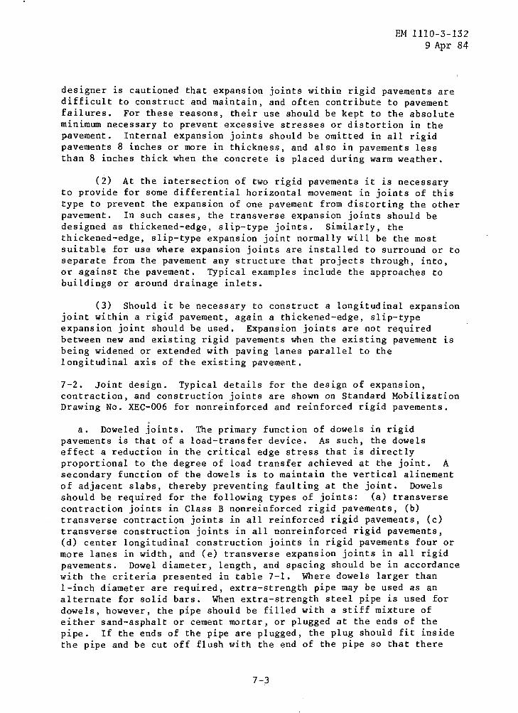
designer is cautioned that expansion joints within rigid pavements aredifficult to construct and maintain, and often contribute to pavementfailures . For these reasons, their use should be kept to the absoluteminimum necessary to prevent excessive stresses or distortion in thepavement . Internal expansion joints should be omitted in all rigidpavements 8 inches or more in thickness, and also in pavements lessthan 8 inches thick when the concrete is placed during warm weather .
(2) At the intersection of two rigid pavements it is necessaryto provide for some differential horizontal movement in joints of thistype to prevent the expansion of one pavement from distorting the otherpavement . In such cases, the transverse expansion joints should bedesigned as thickened-edge, slip-type joints . Similarly, thethickened-edge, slip-type expansion joint normally will be the mostsuitable for use where expansion joints are installed to surround or toseparate from the pavement any structure that projects through, into,or against the pavement . Typical examples include the approaches tobuildings or around drainage inlets .
(3) Should it be necessary to construct a longitudinal expansionjoint within a rigid pavement, again a thickened-edge, slip-typeexpansion joint should be used . Expansion joints are not requiredbetween new and existing rigid pavements when the existing pavement isbeing widened or extended with paving lanes parallel to thelongitudinal axis of the existing pavement .
7-2 . Joint design . Typical details for the design of expansion,contraction, and construction joints are shown on Standard MobilizationDrawing No . XEC-006 for nonreinforced and reinforced rigid pavements .
a . Doweled joints . The primary function of dowels in rigidpavements is that of a load-transfer device . As such, the dowelseffect a reduction in the critical edge stress that is directlyproportional to the degree of load transfer achieved at the joint . Asecondary function of the dowels is to maintain the vertical alinementof adjacent slabs, thereby preventing faulting at the joint . Dowelsshould be required for the following types of joints : (a) transversecontraction joints in Class B nonreinforced rigid pavements, (b)transverse contraction joints in all reinforced rigid pavements, (c)transverse construction joints in all nonreinforced rigid pavements,(d) center longitudinal construction joints in rigid pavements four ormore lanes in width, and (e) transverse expansion joints in all rigidpavements . Dowel diameter, length, and spacing should be in accordancewith the criteria presented in table 7-1 . Where dowels larger than1-inch diameter are required, extra-strength pipe may be used as analternate for solid bars . When extra-strength steel pipe is used fordowels, however, the pipe should be filled with a stiff mixture ofeither sand-asphalt or cement mortar, or plugged at the ends of thepipe . If the ends of the pipe are plugged, the plug should fit insidethe pipe and be cut off flush with the end of the pipe so that there
7-3
EM 1110-3-1329 Apr 84
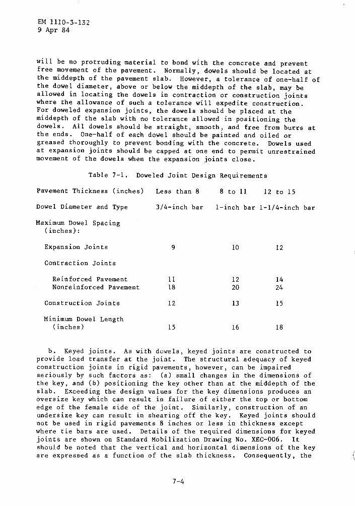
will be no protruding material to bond with the concrete and preventfree movement of the pavement . Normally, dowels should be located atthe middepth of the pavement slab . However, a tolerance of one-half ofthe dowel diameter, above or below the middepth of the slab, may beallowed in locating the dowels in contraction or construction jointswhere the allowance of such a tolerance will expedite construction .For doweled expansion joints, the dowels should be placed at themiddepth of the slab with no tolerance allowed in positioning thedowels . All dowels should be straight, smooth, and free from burrs atthe ends . One-half of each dowel should be painted and oiled orgreased thoroughly to prevent bonding with the concrete . Dowels usedat expansion joints should be capped at one end to permit unrestrainedmovement of the dowels when the expansion joints close .
Table 7-1 . Doweled Joint Design Requirements
b . Keyed joints . As with dowels, keyed joints are constructed toprovide load transfer at the joint . The structural adequacy of keyedconstruction joints in rigid pavements, however, can be impairedseriously by such factors as : (a) small changes in the dimensions ofthe key, and (b) positioning the key other than at the middepth of theslab . Exceeding the design values for the key dimensions produces anoversize key which can result in failure of either the top or bottomedge of the female side of the joint . Similarly, construction of anundersize key can result in shearing off the key . Keyed joints shouldnot be used in rigid pavements 8 inches or less in thickness exceptwhere tie bars are used . Details of the required dimensions for keyedjoints are shown on Standard Mobilization Drawing No . XEC-006 . Itshould be noted that the vertical and horizontal dimensions of the keyare expressed as a function of the slab thickness . Consequently, the
7-4
Pavement Thickness (inches)
Dowel Diameter and Type
Maximum Dowel Spacing(inches) :
Less than 8
3/4-inch bar
8 to 11
1-inch bar
12 to 15
1-1/4-inch bar
Expansion Joints 9 10 12
Contraction Joints
Reinforced Pavement 11 12 14Nonreinforced Pavement 18 20 24
Construction Joints 12 13 15
Minimum Dowel Length(inches) 15 16 18

correct dimensions for the key must be determined for each thickness ofpavement . For all thicknesses of pavement where keyed joints may beused, however, the center of the key should be located at the middepthof the slab .
c . Thickened-edge joints . Thickened-edge type joints may be usedfor all types of expansion joints with the exception of transverseexpansion joints within rigid pavements . When thickened-edge jointsare used, the amount of increased thickness at the edge should beapproximately one-fourth of the design thickness of the main portion ofthe pavement . The thickening should start at a distance of not lessthan 3 feet from the joint and taper uniformly to the full requiredthickness at the joint .
7-3 . Joint spacing . For improved pavement performance and lowermaintenance costs, it is desirable to keep the number of joints to aminimum by using the maximum joint spacings that will satisfactorilycontrol cracking . Under certain conditions where temperature changesare moderate and high humidity prevails, joint spacings greater thanthose indicated herein may be satisfactory .
a . Nonreinforced pavements . Transverse contraction joints shouldbe constructed across each paving lane, at intervals not less than12-1/2 feet nor more than 25 feet . The joint pattern should be madeuniform throughout any major paved area . Each joint should be straightand continuous from edge to edge of the paving lane, and extend acrossall paving lanes for the full width of the paved area . The staggeringof joints in adjacent paving lanes should not be permitted . Themaximum spacing of transverse joints that will effectively controlcontraction cracking will vary appreciably depending on pavementthickness, climatic conditions, effective subgrade restraint,coefficients of thermal expansion of the concrete, and othercharacteristics of the aggregate, cement, etc . The joint spacingsshown in the following tabulation have given satisfactory control ofcontraction cracking in most instances and should be used as a guidesubject to modification based on available information regarding localconditions . Experience has shown that under traffic, oblong slabs tendto crack into smaller slabs of nearly equal dimensions . This isparticularly true for thin pavements . Therefore, it is desirable tokeep the ratio of slab length to width as near unity as practicable .In no case should the slab length exceed the width by more than 25percent .
7- 5
EM 1110-3-1329 Apr 84
PavementThickness, inches
Spacing ofCont raction Joints, feet
Less than 9 12 .5 to 159 to 11 15 to 20More than 11 20 to 25

EM 1110-3-1329 Apr 84
b . Reinforced pavements . Transverse contraction joints inreinforced rigid pavements should be constructed across each pavinglane, perpendicular to the pavement centerline, and at intervals of notless than 25 feet nor more than 75 feet . Allowable slab widths orlengths can be determined directly from figure 6-1 for yield strengthsof either 56,000 or 60,000 lb/in 2 . Each joint should be straight andcontinuous from edge to edge of the paving lane and should extendacross all paving lanes for the full width of the paved area .
7-4 . Joint sealing . All joints in rigid pavements should be sealedwith a sealing compound to prevent infiltration of surface water andsolid materials into the joint openings . In areas of heavy spillage ofdiesel fuel or lubricants, a jet-fuel-resistant sealant will be used .In some climates, joint sealing may not be required . Local sources ofinformation, such as state highway departments, should be investigated .

CHAPTER 8
OPEN STORAGE AREAS
EM 1110-3-1329 Apr 84
8-1 . Parking areas . Rigid pavement for parking areas may be providedat U . S . Army installations where vehicular traffic or local conditionsjustify this type of construction . Normally, parking areas areprovided to accommodate passenger cars and other light vehicles andshould be designed for Category I traffic . Pavement jointing detailsshould be determined in accordance with criteria for roads and streetsas given previously in this manual .
8-2 . Motor pools or motor storage areas . Rigid pavements for serviceand storage areas at motor pools or motor storage areas may be providedat U . S . Army installations where vehicular traffic and/or localconditions justify this type of construction .
a . Administration vehicles . Rigid pavements at motor pools ormotor storage areas designated to accommodate administrative vehiclesshould be designed for Category I traffic . The floor-slab thickness invehicular-maintenance buildings will be determined using a rigidpavement design index of 1 . Joints will be sealed with a materialresistant to spilled fuels and lubricants .
b . General purpose motor pools or motor storage areas . Generalpurpose motor pools or motor storage areas should be designed toaccommodate all pneumatic-tired vehicles having gross weights (empty)not exceeding 30,000 pounds, and track-laying vehicles having grossweights not exceeding 25,000 pounds . Where track-laying vehicles mustbe included, rigid pavements should be used to prevent damage to thesurface of the pavement during the turning of these vehicles .Rigid-pavement thickness requirements should be designed for CategoryIII traffic . The floor-slab thickness in vehicular-maintenancebuildings will be determined using a rigid-pavement design index of 3 .Joints will be sealed with a material resistant to spilled fuels andlubricants .
c . Special purpose motor pools or motor storage areas . Specialpurpose motor pools or motor storage areas should be designed toaccommodate any pneumatic-tired vehicle regardless of gross weight oraxle load, and special engineer and ordnance equipment includingdozers, graders, cranes, tank retrievers, tanks, etc . Wheretrack-laying vehicles must be included, rigid pavements should be usedto prevent damage to the surface of the pavement during the turning ofthese vehicles . Rigid-pavement thickness requirements for use bypneumatic-tired vehicles of unlimited weight only should be designedfor Category V traffic . Rigid-pavement thickness requirements fortrack-laying vehicles having gross weights in excess of 40,000 poundsshould be in accordance with criteria given previously in chapter 4 .The floor-slab thickness in vehicular-maintenance buidings will be

EM 1110-3-1329 Apr 84
determined by using a rigid-pavement design index of 5 . Joints will besealed with a material resistant to spilled fuels and lubricants .
8-3 . Open storage of supplies and materials . In areas to be used forthe open storage of supplies and materials, rigid pavements normallyshould be considered only for the driveways and traffic aisles toaccommodate the operating equipment to handle the supplies, materials,and equipment . However, rigid pavements should be provided in alltraffic areas where forklift trucks, small-wheeled tractors, andsmall-wheeled trailers are used for the intertransfer of cratedmaterials, supplies, and equipment . Rigid-pavement design thicknessrequirements should be based on the traffic category appropriate forthe maximum gross weights of the forklift truck vehicles in accordancewith criteria given in chapter 4 . Where rigid pavements are to beprovided for truck-mounted cranes, pavement thickness requirementsshould be based on Category V traffic . For crawler-mounted cranes,pavement thickness requirements should be based on the appropriatemaximum gross weights to be encountered . Other pavement requirementsand jointing details should be in accordance with criteria for roadsand streets as given previously in this manual .

9-1 . General . Normally, overlays of existing pavements are used fortwo reasons : (a) to increase the load-carrying capacity of an existingpavement, or (b) to correct a defective surface condition on theexisting pavement . Of these reasons, the first requires a structuraldesign procedure for determining the thickness of overlay, whereas thesecond requires only a thickness of overlay sufficient to correct thesurface condition, and no increase in load-carrying capacity isconsidered . The design method for overlays included herein is todetermine the thickness required to increase load-carrying capacity .
9-2 . Definitions and symbols for overlay pavement design . Thefollowing terms and symbols apply to the design of overlay pavementsand are defined for the purpose of clarity .
a . Definitions .
CHAPTER 9
OVERLAY PAVEMENTS
EM 1110-3-1329 Apr 84
(1) Rigid base pavement - Existing pavement to be overlaid andis composed of Portland cement concrete .
(2) Flexible base pavement - Existing pavement to be overlaidand is composed of bituminous concrete, base, and subbase courses .
(3) Composite pavement - Existing pavement to be overlaid and iscomposed of an all-bituminous or flexible overlay on a rigid basepavement .
(4) Overlay pavement - A rigid or nonrigid pavement constructedon an existing base pavement to increase load-carrying capacity .
(5) Rigid overlay - An overlay pavement and is composed ofportland cement concrete .
(6) Nonrigid overlay - An overlay pavement and is composed ofall-bituminous concrete or a combination of bituminous concrete, base,and subbase courses .
(7) All-bituminous overlay - A nonrigid overlay composed ofbituminous concrete for the full depth .
(8) Flexible overlay -- A nonrigid overlay composed of bituminousconcrete surface and granular base and subbase courses .
b . Symbols . The following symbols are used .
(1) k Modulus of subgrade reaction, lb/in 3 .

EM 1110-3-1329 Apr 84
(2) CBR California bearing ratio .
(3) R Concrete flexural strength, lb/in2 .
(4) h Existing rigid pavement thickness, inches .
(5) ho Rigid overlay thickness, inches .
(6) t Nonrigid overlay thickness, inches .
(7) C Coefficient depending upon structural condition of rigidbase pavement .
(8) hd Exact thickness of rigid pavement that would be requiredif placed directly on the foundation . hd is determined from figure 5-1using the modulus of subgrade reaction, k . For rigid overlays, theflexural strength, R, will be the 28-day strength of the overlay . Fornonrigid overlays, the flexural strength to be used for thedetermination of hd will be that of the rigid base pavement .
(9) td Exact thickness of flexible pavement that would berequired if placed directly on the subgrade . The thickness isdetermined from design procedures presented in EM 1110-3-131 .
9-3 . Preparation of existing pavement . Inspections of the existingpavement should be made to locate all areas of distress in the existingpavement and to determine the cause of the distress . Areas showingextensive and progressive cracking and/or foundation failures should beremoved and repaired prior to the overlay . This is especially true ofareas where excessive pumping, bleeding of water at joints or cracks,excessive settlement in foundation, subgrade rutting, slides, etc .,have occurred . If voids are detected beneath the base pavement, theyshould be filled by grouting prior to the overlay . The surface of theexisting pavement should be conditioned for the various types ofoverlay as follows :
a . Rigid overlay . The surface of the existing base pavement shouldbe cleaned of all foreign matter, spalled concrete, extruded jointseal, bituminous patches, and other materials that would prevent theoverlay from bonding to the base pavement .
b . Flexible overlay . No special conditioning of the existingsurface is required other thanaggregate and/or concrete .
c . All-bituminous overlay .will be cleaned of all foreignpatches, spalled concrete, andcracks, or spalled areas in thehot sand-asphalt mixture should
the removal of debris and loose
The surface of the existing pavementmatter, fat spots in existing bituminousextruded joint seal . When the joints,existing pavement are wide enough, abe used to fill them to the grade of
9-2

the existing pavement . Wedge courses of bituminous concrete should beused to bring the existing pavement to proper grade when necessary .Prior to placement of the all-bituminous overlay, a tack coat should beapplied to the existing pavement surface .
9-4 . Rigid overlay of rigid base pavements . The criteria contained inparagraph 1-5 are applicable to the design of rigid overlays . Theplacement of forms and the determination of thickness for the rigidoverlay should be as follows :
a . Placing forms . If it is necessary to drill holes in theexisting rigid pavement to provide anchorage for the overlay pavementforms, the size of the holes and the number drilled should be theminimum that will adequately accomplish the purpose . The holes shouldnot be located close to joints or cracks where they might inducespalling, and they should be spaced or staggered so as to minimizeadditional cracking .
b . Determination of overlay thickness . The thickness of rigidpavement overlay necessary to increase the load-carrying ability of anexisting rigid base pavement should be determined by one of thefollowing equations :
Equation 9-1 is for the condition of partial bond developing betweenthe rigid overlay and rigid base pavement . It should be used todetermine the overlay thickness when no bond-breakingmedium is used, such as a tack coat, sand-asphalt patch, orleveling course, etc .
h o
h o =
1 .4 1 .4hd - Ch
EM 1110-3-1329 Apr 84
(eq 9-1)
(eq 9-2)
Equation 9-2 is for the condition of no bond developing between therigid overlay and rigid base pavement . It should be used to determinethe overlay thickness when a sand-asphalt leveling course, bituminouspatch, or tack coat, etc ., is used on the surface of the existing basepavement . The coefficient C is determined by the structural conditionof the rigid base pavement . Its numerical value should be establishedas follows, based upon a visual inspection of the existing pavement .
C = 1 .00 when the slabs are in good condition, with little orno structural cracking .
C = 0 .75 when the slabs show initial cracking due to loading,but little or no multiple cracking .

EM 1110- 3-1329 Apr 84
C = 0 .50 when a larger number of slabs show multiple cracking,but the majority of slabs are intact or contain only singlecracks .
C = 0 .35 when the majority of slabs show multiple cracking .
In both of the equations, hd is the exact thickness, to the nearesttenth of an inch, of monolithic rigid pavement that would be requiredfor the design traffic conditions, and is determined from figure 5-1 .The design thickness of all overlay slabs should be in multiples of 1full inch . Whenever the calculations show agreater than one-quarter, the next full inchThe minimum rigid overlay pavement thicknessit is reinforced or bonded to the rigid basethe following paragraphs .
c . Joints . Unless a bond-breaking medium is used between the rigidoverlay and rigid base pavement, or the rigid overlay is reinforced,joints should be provided in the overlay which coincide with all jointsin the base pavement . However, it is not necessary that the joints inthe overlay be of the same type as those in the existing base pavement .When an appreciable thickness of bond-breaking medium is used, 1/4 inchor more, the matching of joints in the overlay and base pavement is notnecessary but is advisable .
9-5 . Reinforced rigid overlay of rigid base pavements . Reinforcedrigid overlays of existing rigid pavements should be used only whenthey prove to be more economical, when it is necessary to reduce thethickness of the overlay to meet grade requirements, or for otherreasons where it is impractical or impossible to provide the requiredstrengthening by means of a nonreinforced rigid overlay . The thicknessof nonreinforced rigid overlay should be determined in accordance withparagraph 9-4, and the percentage of steel and thickness reductionshould be determined in accordance with chapter 6 of this manual . Whenreinforced rigid overlays are used, the minimum thickness of overlayshould be 4 inches . It is not necessary to provide joints in thereinforced rigid overlay which coincide with all joints in the basepavement ; however, when a joint is required in the overlay, it shouldcoincide with a joint in the base pavement .
9-6 . Rigid overlays of flexible base and composite base pavements .
a . Flexible base pavements . A rigid overlay of an existingflexible pavement should be designed in the same manner as a rigidpavement on grade, in accordance with chapter 5 . A modulus of subgradereaction, k, should be determined by a plate-bearing test made on thesurface of the existing flexible pavement . I£ not practicable todetermine k from a plate-bearing test, conservative value may beestimated from figure 2-1 by comparing the existing flexible pavement
9-4
fractional inch thicknessthickness should be used .should be 6 inches unlesspavement, as described in

with a well-packed gravel or consolidated clay . The followinglimitations, however, should apply :
EM 1110-3-1329 Apr 84
- In no case should a k value greater than 500 lb/in3 be used .
- The plate-bearing test to determine the k value should beperformed on the flexible pavement at a time when the temperatureof the bituminous concrete is of the same order as the ambienttemperature of the hottest period of the year in the locality ofthe proposed construction .
b . Composite base pavements . Two conditions of composite pavementcan be encountered when considering a rigid overlay . When thecomposite pavement is composed of a rigid base pavement with less than4 inches of all-bituminous overlay, the required thickness of rigidoverlay should be determined using the no-bond overlay equation 9=2 .If the composite pavement is composed of a rigid base pavement with 4inches or more of either all-bituminous or flexible overlay, therequired thickness of rigid overlay should be determined in accordancewith paragraph 9-6 .a .
9-7 . Nonrigid overlay of rigid base pavements .
a . Design procedure . The design procedure presented hereindetermines the thickness of nonrigid-type overlay necessary to increasethe load-carrying capacity of existing rigid pavement . This method islimited to the design of the two types of nonrigid overlay defined inparagraph 9-2 . The selection of the type of nonrigid overlay to beused for a given condition is dependent only on the required thicknessof the overlay . Normally, the flexible overlay should be used when therequired thickness of overlay is sufficient to incorporate a minimum4-inch compacted layer of high-quality base-course material plus therequired thickness of bituminous concrete surface courses . For lesserthicknesses of nonrigid overlay, the all-bituminous overlay should beused . The method of design is referenced to the deficiency inthickness of the existing rigid base pavement and assumes that acontrolled degree of cracking will take place in the rigid basepavement during the design life of the pavement .
b . Determination of overlay thickness . The thickness of nonrigidoverlay (all-bituminous or flexible) required to increase the loadcarrying capacity of an existing rigid base pavement to a designatedlevel should be determined by the following equation :
t = 2 .5(Fhd - Ch)
where hd is the exact thickness (to the nearest 1/10 inch) determinedfrom figure 5-1 using the flexural strength of the existing rigid basepavement, the measured or estimated subgrade modulus, k, and theappropriate rigid-pavement design index . The factor F will be :
.1 fora design index = 1 ; .7 for a design index = 2 ; .9 for a design index =
9-5

EM 1110-3-1329 Apr 84
3 ; and .95 for design indices 4 through 10 . The C factor is acoefficient depending on the structural condition of the existing rigidbase pavement . Numerical values of C are determined as follows :
C = 1 .00 when rigid base pavement slabs contain only nominalinitial cracking .
C = 0 .75 when the rigid base pavement slabs contain multiplecracks and numerous corner breaks .
The overlay thickness, t, used in design should be determined to thenearest 1 inch .
c . All-bituminous overlay . The all-bituminous overlay is requiredonly when the combined thickness of a minimum 4-inch compacted basecourse and the required thickness of bituminous surface course exceedsthe design thickness, t . There is no limitation, other than theeconomics of construction, on the maximum thickness of all-bituminousoverlay that can be used . The bituminous concrete overlay should bedesigned in accordance with the requirements of EM 1110-3-131 . A tackcoat is required between the rigid base pavement and the all-bituminousoverlay .
A minimum thickness of 2 inches will be required for anall-bituminous overlay designed to increase the structural capacity ofa base pavement . No limitation is placed on the minimum thickness ofan all-bituminous overlay when used as a maintenance measure to improvepavement surface smoothness .
d . Flexible overlay . A flexible overlay (bituminous surface courseand granular base course) may be used when the design thickness, t, islarge enough to permit the use of a 4-inch compacted base course plusthe required thickness of bituminous surface course . The requiredthickness of bituminous surface course and the design of the surfacecourse should be in accordance with EM 1110-3-131 . The base-coursematerial should be a crushed aggregate material exhibiting a CBR of 100for the full depth . The gradation and compaction requirements of thebase course should be determined from EM 1110-3-131 .
9-8 . Overlays in frost regions . Whenever the subgrade is susceptibleto differential heaving or weakening during the frost-melt period, theoverlay design should meet the requirements for frost action as givenin EM 1110-3-138 . When it is determined that distress in an existingpavement has been caused by differential heaving due to frost action,an overlay may not correct the condition unless the combined thicknessof the pavement is sufficient to prevent substantial frost penetrationinto the underlying frost-susceptible material .

APPENDIX A
DESIGN EXAMPLES
A-1 . Example of a nonreinforced rigid pavement design . Let it be'required to design a nonreinforced rigid pavement for a road in a ruralarea on rolling terrain, to carry the following traffic :
Average .daily volume
3,500 vehicles per laneTrucks, 2-axle
150 per lane per dayTrucks, 3 or more axles
50 per lane per day
In accordance with EM 1110-3-130 and based on the definitions oftraffic categories given previously, this traffic would be evaluated asrequiring a Class C road designed for Category IV traffic . However formobilization work, Class C translates to a Class B pavement . Fromtable 5-1, the rigid pavement design index for a B-IV pavement is 4 .Assuming a 28-day flexural strength for the concrete of 675 lb/in2 anda modulus of subgrade reaction of 100 lb/in 3 , the required pavementthickness as indicated by figure 5-1 is approximately 7 .3 inches .Since the fractional thickness is greater than 1/4 inch, the designthickness would be 8 inches . To illustrate the design procedure whentraffic includes track-laying vehicles, assume that in addition to thepneumatic-tired traffic used in the previous example, the designer mustprovide for an average of 60 tanks per lane per day and that the grossweight of each tank is 50,000 pounds . The 50,000-pound gross weightwould be classified as Category V traffic since it exceeds the maximumof 40,000 pounds permitted for track-laying vehicles in Category IV .Inasmuch as the tank traffic exceeds 40 per day, the rigid pavementdesign index would be based on the next higher traffic volume given intable 5-1, which is 100 per day . Thus from table 5-1, the design indexfor a Class B street would be 5 . Assuming the same 28-day flexuralstrength and modulus of subgrade reaction as in the previous example,the required pavement thickness as indicated by figure 5-1 isapproximately 7 .9 inches and would require a design thickness of 8inches . To illustrate the procedure for combining both forklift trucksand track-laying vehicles with pneumatic-tired vehicles, let it berequired to design a rigid pavement on rolling terrain for thefollowing traffic :
In accordance with EM 1110-3-130, this traffic on rolling terrain wouldbe evaluated as requiring a Class D road or Class E street . From table5-1, the 50-kip, track-laying vehicles are classified as Category V
EM 1110-3-1329 Apr 84
Average daily volume 750 vehicles per laneTrucks, 2-axle 100 per lane per dayTrucks, 3 or more axles 40 per lane per dayTrack-laying vehicles, 50,000 pounds 50 per lane per dayTrack-laying vehicles, 80,000 pounds 20 per lane per dayForklift trucks, 25,000 pounds 2 per lane per day

EM 1110-3-1329 Apr 84
traffic . For a frequency of 50 of these vehicles per lane per day, therigid pavement design index would be 5 .
The 80-kip, track-layingvehicles are classified as Category VI traffic . For a frequency of 20of these vehicles per lane per day, the rigid pavement design indexwould be 6 . The 25-kip, forklift trucks are classified as Category VIItraffic . For a frequency of two of these vehicles per lane per week,the design index would be 5 . Thus it can be seen that the 80-kip,track-laying vehicle traffic is the governing factor as it requires thehighest design index . Assuming the same 28-day flexural strength andmodulus of subgrade reaction as in the previous design examples, therequired pavement thickness from figure 5-1 is 9 .0 inches .
A-2 . Example of a reinforced rigid pavement design . Let it berequired to design a reinforced rigid pavement for the same set ofconditions used in example A-1 . Using the value of hd of 7 .5 inches,the percentage of longitudinal reinforcing steel S required to reducethe pavement thickness to 7 inches obtained from figure 6-1 as 0 .07percent . Similarly, the percentage of longitudinal reinforcing steelrequired to reduce the pavement thickness to 6 inches is 0 .21 percent .The percentage of transverse reinforcing steel would be either 0 .035for a design thickness of 7 inches or 0 .11 for a design thickness of 6inches . The choice of which percentage of steel reinforcement to useshould be based on economic considerations as well as on foundation andclimatic conditions peculiar to the project area . If the yieldstrength of the steel is assumed to be 60,000 lb/in2 , the maximumallowable spacing of the transverse contraction joints would be 38 feetfor 0 .07 percent longitudinal steel, and 76 feet would be indicated asthe maximum spacing for 0 .21 percent longitudinal steel . In the lattercase, the maximum permissible spacing of 75 feet would be used .

Government Publications .
Military Standards .
APPENDIX B
REFERENCES
Department of.-the . Army -Publications .
EM-1110-3-130
Geometrics for Roads, Streets,Walks, and Open Storage Areas .
EM-1110-3-131
Flexible Pavements for Roads,Streets, Walks, and Open StorageAreas .
EM-llli)-3-135
Standard Practice for ConcretePavements .
EM-1110-3-136
Drainage and Erosion Control .
EM-1110-3-137
Soil Stabilization for Pavements .
EM-1110-3-138
Pavement Criteria for SeasonalFrost Conditions .
Nongovernment Publications .
American Society for Testing and Materials (ASTM),1916 Race St ., Philadelphia, PA . 19103
EM 1110-3-1329 Apr 84
C 73-75
Flexural. Strength of Concrete (UsingSimple Beam with Third-PointLoading) .
D .1556-64
Density of Soil In Place by the(R 1974)
Sand-Cone Method .
D 1557-78
Moisture-Density Relations of Soilsand Soil-Aggregate Mixtures (Using10-lb . (4 .5-kg) Rammer and .18 in .(457-mm) Drop) .
MI(,-STD-619B Unified Soil Classification Systemfor Roads, Airfields, Embankments,and Foundations .
MII,-ST!)-621A Test Method for Pavement Subgrade,& Notices .1, 2 Subbase, and Base-Course Materials .

EM 1110-3 ; y329 Apr 84
D 2167-66
Density of Soil in Place by the(R 1977)
Rubber-Balloon Method .
D 2922-81
Density of Soil and Soil-Aggregatein Place by Nuclear Methads(Shallow Depth ) .