engineering survey - transport.nt.gov.au · engineering survey ... auspos online processing service...
TRANSCRIPT

Engineering Survey April 2017 Page 1
STANDARD SPECIFICATION FOR
ENGINEERING SURVEY
ROAD PROJECTS
DEPARTMENT OF INFRASTRUCTURE PLANNING AND LOGISTICS
Revision 1 – 10th April 2017

Engineering Survey April 2017 Page 2
Contents ENGINEERING SURVEY .......................................................................................................... 1
Contents .................................................................................................................................... 2
1. Purpose .............................................................................................................................. 4
2. Scope ................................................................................................................................. 4
3. References ......................................................................................................................... 4
3.1 Australian Standards ................................................................................................... 4
3.2 Legislation ................................................................................................................... 4
3.3 Surveying Standards & Guidelines ............................................................................. 4
4. Definitions & Acronyms ...................................................................................................... 4
5. Quality Management Systems ........................................................................................... 5
6. Qualification of Surveyors .................................................................................................. 6
7. Safe Work Practices ........................................................................................................... 6
7.1 Work In The Vicinity of Power and Water Corporation Assets ................................... 6
7.2 Work In The Vicinity of Gas Pipelines and Fuel Lines ................................................ 6
7.3 Work Within Railway Reserves ................................................................................... 7
8. Cultural and Heritage sites ................................................................................................. 7
9. Entry to Land ...................................................................................................................... 7
10. Traffic Control ................................................................................................................. 7
11. Survey ............................................................................................................................. 8
11.1 General .................................................................................................................... 8
11.2 Survey Datum .......................................................................................................... 8
11.3 Field Marking ........................................................................................................... 9
11.4 Accuracy .................................................................................................................. 9
11.5 Boundaries ............................................................................................................ 12
11.6 Natural and Artificial Surfaces ............................................................................... 12
11.7 Pits ......................................................................................................................... 12
11.8 Bedrock ................................................................................................................. 12
11.9 Kerbs and Gutters ................................................................................................. 12
11.10 Vegetation ............................................................................................................. 13
11.11 Structures .............................................................................................................. 13
11.12 Underground Services ........................................................................................... 13
11.13 Railway .................................................................................................................. 14
11.14 Existing Roads and Tracks .................................................................................... 14
11.15 Fuel and Gas Pipes ............................................................................................... 14
11.16 Electricity ............................................................................................................... 14
11.17 Water Supply ......................................................................................................... 15
11.18 Telecommunications .............................................................................................. 16
11.19 Sewerage .............................................................................................................. 16
11.20 Stormwater Drainage ............................................................................................. 16
11.21 Photography .......................................................................................................... 17
12. Digital Survey Data ....................................................................................................... 17
13. Survey Report ............................................................................................................... 17
14. Lodged Information ....................................................................................................... 18
15. Transfer of Deliverables ................................................................................................ 18
Appendix A Data Capture Methods ................................................................................... 19
Appendix B Pricing Schedule ............................................................................................ 21

Engineering Survey April 2017 Page 3
Appendix C AutoCAD File Structure Table ........................................................................ 23

Engineering Survey April 2017 Page 4
1. PURPOSE
This document specifies the minimum requirements for engineering surveys conducted by or for the Northern Territory Government.
Perform and present all survey work in accordance with the following requirements to ensure that uniformity and consistency of detail, format, quality and procedure is achieved.
2. SCOPE
This document applies to all engineering ground survey commissioned for the purposes of engineering design, analysis and computation.
Any project specific requirements including exemptions or additions to this specification shall be specified in the Project Survey Brief.
Further advice and information can be obtained by contacting the relevant Project Manager.
3. REFERENCES
3.1 AUSTRALIAN STANDARDS
AS 1100.401 (1984), Technical drawing Part 401: Engineering survey and engineering survey design drawing
AS 1742.3 (2009), Manual of uniform traffic control devices Part 3: Traffic control for works on roads
AS/NZS ISO9001 (2008), Quality Management Systems
AS 5488 (2013) Classification of Subsurface Utility Information
3.2 LEGISLATION
2013 Aboriginal Sacred Sites Act, Northern Territory
2012 Dangerous Goods Act, Northern Territory
2015 Energy Pipelines Act, Northern Territory
2016 Heritage Act, Northern Territory
2013 Licensed Surveyors Act, Northern Territory
2016 Work Health and Safety (National Uniform Regulations) Act, Northern Territory
3.3 SURVEYING STANDARDS & GUIDELINES
2014 Standard for the Australian Survey Control Network, Version 2.1, ICSM
2014 Guideline for the Adjustment and Evaluation of Survey Control, Version 2.1, ICSM
2014 Guideline for Control Surveys by GNSS, Version 2.1, ICSM
2014 Guideline for Control Surveys by Differential Levelling, Version 2.1, ICSM
2014 Guideline for Conventional Traverse Surveys, Version 2.1, ICSM
2014 Guideline for the Installation and Documentation of Survey Control Marks, Version 2.1, ICSM
4. DEFINITIONS & ACRONYMS
The following terms used in this procedure have the specific meanings indicated:
AHD Australian Height Datum – national height datum based on mean sea level and adopted in 1971
AUSGeoid Interpolation grid 1.8 km x 1.8 km used to convert heights between the GDA ellipsoid and the AHD
AUSPOS Online processing service provided by Geoscience Australia for calculation of GDA coordinates and derived AHD from static GNSS data
BM Bench Mark – permanent mark placed in a vertically stable location for providing height reference, usually AHD
Consultant The legal entity that is contracted to execute the survey

Engineering Survey April 2017 Page 5
CRM Coordinated Reference Mark – permanent mark placed in a stable location for providing position and height reference. These marks are registered by the Surveyor General.
CSF Combined Scale Factor – used to convert a distances at ground level to corresponding distance on the grid such as MGA. It is the product of the point scale factor and height factor. Ground distance x CSF = Grid distance. To convert a whole project from ground level coordinates to MGA coordinates, scale in X and Y directions by the average project CSF.
DTM Digital Terrain Model – three dimensional model of the surface features of the site
FTP File Transfer Protocol - a standard network protocol used to transfer computer files between a client and server on a computer network
GNSS Global Navigation Satellite System – a constellation of orbiting satellites working in conjunction with a network of ground stations that transmit signals enabling roving receivers on the ground or in the air to determine latitude and longitude
GDA Geocentric Datum Australia – mathematical definition of the earth’s shape with its origin at the centre of mass
GPR Ground Penetrating Radar – device for locating the position and depth of underground features
ICSM Intergovernmental Committee on Surveying and Mapping
IM Indicator Mark – tall mark placed near a ground mark to indicate its location
LiDAR Light Detection and Ranging – technology that uses ultraviolet, visible, or near infrared light to measure distance to objects and capture dense point clouds of information from a mobile platform such as a fixed wing aircraft or helicopter
MGA Map Grid Australia – cartesian coordinates from a Transverse Mercator Projection of GDA latitudes and longitudes
MLS Mobile Laser Scanning - technology that captures dense point clouds of information from a laser scanner mounted on a mobile platform such as a motor vehicle or boat.
RPA Remotely Piloted Aircraft - aircraft that are operated by remote control either fully or intermittently. Often they have autonomous capabilities for routine operations such as collection of imagery over a specified area.
PRP Permanent Reference Point – point of known road chainage
RCM Road Centreline Mark – mark indicating the road centreline on site
RTK Real Time Kinematic – GNSS technology that enables measurement of coordinates and levels in real time
SCM Survey Control Mark – survey mark on site used as a reference for coordinates and levels
SU Survey Uncertainty - is the uncertainty of the horizontal and/or vertical coordinates of a point relative to the survey in which it was observed and is free from the influence of any imprecision or inaccuracy in the datum connection. Therefore, SU reflects only the uncertainty resulting from survey measurements, measurement precisions, network geometry and the choice of constraint. It is expressed at the 95% confidence level.
TLS Terrestrial Laser Scanning - technology that captures dense point clouds of information from a laser scanner mounted at a fixed location during the scanning process.
5. QUALITY MANAGEMENT SYSTEMS
The Consultant shall be certified to and implement the requirements of ISO 9001 Quality Management Systems. The requirements for control and calibration of survey instruments and ancillary equipment used for completing this contract shall be complied with.

Engineering Survey April 2017 Page 6
6. QUALIFICATION OF SURVEYORS
A qualified surveyor shall direct and be responsible for all survey work and able to demonstrate competence in carrying out the required tasks. Minimum qualifications for the survey elements are:
Survey control - A person who holds a Diploma in Surveying, or a recognised equivalent, from a recognised tertiary institution and possesses at least three years appropriate practical experience as a survey party leader.
Engineering Ground Survey - A person who holds a Diploma in Surveying, or a recognised equivalent, from a recognised tertiary institution and possesses at least three years appropriate practical experience as a survey party leader.
Cadastral Boundary Model – A surveyor licensed under the NT Licensed Surveyors Act.
7. SAFE WORK PRACTICES
Further to the Conditions of Tendering and Contract, the Consultant shall ensure that their employees, agents or sub-consultants or their employees, agents or sub-contractors or their employees or agents comply in so far as they are applicable to the execution of work under the contract with the requirements of:
The Work Health and Safety (National Uniform Regulations) Act
The Dangerous Goods Act
The Australian Standards
Darwin Port Operations Pty Ltd
Power and Water Corporation
Telstra
NT Gas Pty Ltd
Origin Energy
Central Energy Australia Pty Ltd
Genesee & Wyoming Australia Pty Ltd
7.1 WORK IN THE VICINITY OF POWER AND WATER CORPORATION ASSETS
Prior to commencing work in the vicinity of any sewerage system, high voltage cable or power line or other high voltage structure, the Consultant shall contact the Power and Water Corporation Authorisations Administrator on 08 8924 5156, and obtain and become cognisant with written guidelines or procedures setting out safe practices for working in or adjacent to such hazardous areas.
Whilst working in the vicinity of sewerage systems, high voltage cables or power lines or other high voltage structures the Consultant shall follow all directions and instructions issued by the Power and Water Corporation. Opening of any sewerage manholes shall be undertaken by the Power and Water Corporation.
7.2 WORK IN THE VICINITY OF GAS PIPELINES AND FUEL LINES
In accordance with the Energy Pipelines Act, the Consultant shall obtain the written approval of the APA Group on 08 8924 8100 or the relevant asset owner before commencing any of the following activities in the vicinity of high pressure gas pipelines:-
1. Any activities within the pipeline right-of-way which involve construction of any kind including:
excavation for drains, pipelines or sewers,
excavation for buried utilities or services,
construction or maintenance of roads or tracks,
boring of holes for posts or any survey or exploration work involving excavation, explosives or vibration.
2. Any nearby construction activities which are likely to affect the right-of-way, such as re-routing surface water flows, construction of high voltage lines, or erection of large metal structures.
3. Any passage of heavy vehicles and equipment over the pipeline other than on public roads.

Engineering Survey April 2017 Page 7
Whilst working in the vicinity of gas pipelines the Consultant shall follow all directions and instructions issued by the asset owner.
Similarly the Consultant shall follow all directions and instructions issued by the asset owner of fuel lines.
7.3 WORK WITHIN RAILWAY RESERVES
Prior to commencing work within any railway sites, the Consultant shall obtain the consent of Genesee & Wyoming Australia Pty Ltd, and comply with their guidelines or procedures setting out safe practices for working in or adjacent to their sites, phone 08 8984 2000.
Whilst working within railway sites the Consultant shall follow all directions and instructions issued by Genesee & Wyoming Australia Pty Ltd.
8. CULTURAL AND HERITAGE SITES
All prescribed archaeological places and objects are protected under the Heritage Act and the Aboriginal Sacred Sites Act, whether they have been recorded or not and regardless of whether they have been disturbed in the past or otherwise. It is an offence under the Act to damage or remove a heritage place or object.
Known information about cultural and heritage sites will be provided to the Consultant including any:
Certificates from the Aboriginal Areas Protection Authority;
Restrictions by an Aboriginal Land Trust or Land Council
Do not enter aboriginal sacred sites without appropriate authority, and avoid disruption to identified archaeological sites. All conditions under an AAPA Certificate must be adhered to.
The Consultant shall ensure that his employees are aware of the possibility that archaeological and heritage sites may exist within the work area, and of the requirement to notify the Department if a site is encountered.
9. ENTRY TO LAND
The Consultant shall obtain permission from landowners before entering private property. The Principal’s Representative will as necessary provide the Consultant with an appropriate letter to facilitate entry for the purpose of conducting the survey. The Consultant will maintain a record of all contacts made for this purpose.
Where any land proposed for survey is on a Crown Reserve, or is a designated Aboriginal Sacred Site administered under an Aboriginal Land Trust or is protected under Native Title or any other encumbrance, the Consultant shall obtain all necessary clearances or permits from the appropriate authorities and/or occupiers of the land.
New tracks shall not be formed, existing tracks altered, fencing cut, clearing carried out, or damage or disturbance of any kind effected unless strictly necessary for the purpose of the Project Survey Brief and permission and clearances have been obtained. The Consultant shall ensure that such disturbances are the minimum required and shall reinstate, clean up and leave the site as close to its pre-disturbed condition as possible, and a safe condition. The Consultant shall be responsible for the cost of reinstating any damage to property resulting from work carried out under the Project Survey Brief.
10. TRAFFIC CONTROL
Where survey involves working on, or immediately adjacent to, trafficked roads, the Consultant shall obtain the appropriate approvals and take measures for the protection of employees, other road users and property.
The Consultant shall assume responsibility for minimising obstruction and inconvenience to the public, and the safe conduct of traffic through or around the works, 24 hours a day, from commencement to completion of the survey works.
Establish traffic control, as necessary, in accordance with the requirements of Australian Standard AS1742.3, Manual of uniform traffic control devices, Part 3: Traffic control devices for works on roads.
In urban areas, program work and install signs accordingly so that traffic is not impeded during the following hours:
0700 hours to 0900 hours

Engineering Survey April 2017 Page 8
1600 hours to 1730 hours.
Road lanes shall not be closed without prior written permission in the form of a Traffic Management plan approved by the Principal’s Representative.
When required, a Traffic Management Plan prepared by a suitably accredited person must be submitted for the approval of the Principal’s Representative, a minimum of 5 working days prior to commencement of the survey works.
11. SURVEY
11.1 GENERAL
Provide a three-dimensional mathematical representation (model) of the site upon which geometric design, analysis and computation can be based.
Establish permanent survey control marks (SCMs) from which the works can be set out.
Comply with the specific requirements defined in the Project Survey Brief.
All natural and artificial features occurring within the survey project area shall be captured and represented in the digital model as points and strings. Sufficient measurements shall be taken to ensure all points and strings in the digital model accurately reflect their true geometric shape and location.
Provide text annotation to adequately define and describe the following:
Road names.
Rivers, streams or lake or other water course names.
Names and numbers of CRMs, SCMs, BMs or any other control used for the survey or located in the survey project area.
Permanent Reference Point (PRP) distances.
Distance markers legend and distances.
Sign annotation on all signs
Culvert type, size or diameter and number of pipes or boxes. Note; culvert/pipe dimensions shall be internal measurements and description of protection works.
Adjacent property boundaries, parcel numbers and Pastoral Station names
Adjacent fences
Pavement marking
Overhead services
Underground services
Chainages on road structures derived from the closest known PRP
Any other relevant annotation that will assist in the definition of features within the survey area.
11.2 SURVEY DATUM
11.2.1 Coordinate Datum
The horizontal position of field data is to be supplied on the appropriate zone of the current Map Grid of Australia (MGA) datum unless specified otherwise in the Project Survey Brief.
A text tabulation of the identity, coordinates, reduced level and type of mark for each control point is to be included in the data file and shown on the verification plots together with identification of the marks used for horizontal and vertical datum.
11.2.2 Connection to MGA
When an alternative coordinate datum has been specified in the Project Survey Brief, provide a common point at each end of the project establishing the relationship between the assumed coordinate datum and the MGA coordinate system. The alternative coordinate datum must not be similar to MGA.
Include equivalent coordinates, the average Combined Scale Factor (CSF) and the difference in orientation of the north points as a text note in the data file and on the verification plots.

Engineering Survey April 2017 Page 9
11.2.3 Height Datum
Where possible, use Australian Height Datum. Where AHD is not possible height information will be on an assumed datum.
For projects in coastal or marine locations the height difference between AHD and Chart Datum shall be determined where possible.
11.2.4 Chainage Datum
The chainage of the start point of the survey will be derived from the nearest Departmental Permanent Reference Point (PRP) for the road being surveyed.
Refer to the Project Survey Brief for the PRP to be used for this survey.
11.3 FIELD MARKING
11.3.1 Safety
Survey marks may constitute a danger to the public, land owners and users, if visual indicator marks have been interfered with or removed. In locations where this is likely to occur, survey marks are to be driven to ground level and be of a type suitable for the location.
Locate marks in locations where minimum disturbance is likely and they are clear of underground services.
11.3.2 Survey Control Marks (SCM)
Unless already existing, place a minimum of three SCMs to be used for horizontal and vertical control on each project in locations where they will be stable and unlikely to be disturbed by the future works. Locate marks so that they are inter-visible to adjacent marks in each direction. The maximum distance between successive marks is 500 metres.
Each SCM shall be a:
CRM; or
Star Iron not less than 600 mm long; or
Spike not less than 200 mm long; or
Other suitable mark
Uniquely identify each mark by stamping the identity into a solid aluminium tag fixed to the mark or the mark itself for a CRM.
When directed by the Principal and prior to commencing field work, a request shall be made to the Survey Land Records section of the Department’s Survey Branch to request an allocation of CRM numbers and requirements. These generally include:
Proposed location
Construction
Recovery marks
Do not place SCMs within 5 metres of the edge of a road carriageway.
11.3.3 Indicator Marks (IM)
Use pressed metal fence spreaders minimum length 1000 mm.
Place indicator marks at SCMs.
Do not place indicator marks within 5 metres of the edge of a rural road carriageway.
11.4 ACCURACY
11.4.1 Survey Control Marks - Horizontal Accuracy
MGA coordinates shall be determined by connection to at least two CRMs or other registered coordinated marks if existing within 10 km of the project extents. In locations where coordinated control marks do not exist, GNSS data shall be recorded on at least two SCMs and MGA coordinates calculated using the AUSPOS service.

Engineering Survey April 2017 Page 10
The SU of Control Marks shall be no more than a maximum horizontal circular confidence of radius (r) at the 95% confidence interval.
r = 2.45 x 15(K+0.2) mm
Where:
K = distance between marks in km
The evaluation of the survey control network shall be in accordance with the current Guideline for the Adjustment and Evaluation of Survey Control.
11.4.2 Survey Control Marks - Vertical Accuracy
The levels of all survey control points shall be established by differential levelling or GNSS observations separately or in combination:
Two-way differential levelling from a known Bench Mark (BM) in accordance with the Guideline for Control Surveys by Differential Levelling, or
One-way differential levelling between at least two known Bench Marks in accordance with the Guideline for Control Surveys by Differential Levelling, or .
Static GNSS methods between at least three known Bench Marks in accordance with Guideline for Control Surveys by GNSS.
The level difference, in metres, between the forward and backward levelling of a two-way run or between two known Bench Marks in a single run shall not exceed 12√K mm, where K is the distance in kilometres and K is greater than or equal to 1 km. The vertical accuracy for distances less than 1 km shall be on a pro rata basis relative to the 1 km tolerance, 12 mm.
11.4.3 Measurement Accuracy for Points and Linear Features
Survey control, technologies, observation methodologies, error mitigation and processing shall ensure that measurements to point and linear features are within the specified positional and height accuracy requirements.
The accuracies stated are relative to the adopted values of the nearest survey control mark.
Table 1: Measurement Accuracy for Point and Linear Feature Classification
Classification Horizontal accuracy Vertical accuracy
A 15 mm 10 mm
B 20 mm 15 mm
C 50 mm 20 mm
D 100 mm 40 mm
E 200 mm 50 mm
F 200 mm 100 mm
G 200 mm 200 mm
Note: Accuracies are at the 95% Confidence Interval

Engineering Survey April 2017 Page 11
Table 2: Feature Type and Accuracy Classification
Feature Type Classification
Survey control features A
Kerbs, Rails, Boundary Marks, Bridges B
Inverts, Paved road features, A/G services (Headwalls, Pits, Manholes, Valve covers etc.)
C
Un-paved road features, Road furniture, U/G Services (direct measured)
D
Ground features, Natural surface, Open drains E
Trees F
U/G Services (indirect measured) G
Regardless of defined accuracies, linear and point features must adhere to their true position relative to the position of adjacent features.
11.4.4 Interpolated Points on Feature Strings
Linear features shall be captured such that the accuracies of interpolated points on the defined string are within twice the nominated accuracy for the relevant classification.
11.4.5 Barrier Strings
The production of the final triangulation mesh is to be controlled through the use of barrier strings/break lines. These strings will represent features that form the edges of triangles in the model, such as tops of banks or road shoulders.
The barrier string attribute is implicit within the feature coding and shall be the only acceptable form of triangle modification. All barrier strings appearing in the survey data must be coded in the field.
The triangulation model must be capable of re-creation directly from the survey information supplied, without the need for interactive editing.
11.4.6 Surface Model
Within the survey project area, sufficient points and linear features shall be captured to ensure that the surface model meets the following accuracy requirements.
Points interpolated on the planar triangulation surface, shall be within the vertical accuracy nominated in the table below for the relevant surface type.
Table 3: Interpolated Surface Accuracy
Surface type Vertical Accuracy
Paved surface 40 mm
Formed surface 80 mm
Natural surface 200 mm
Note: Accuracies are at the 95% Confidence Interval
11.4.7 Verification of the Survey Model
Unless specified otherwise in the Project Survey Brief all methods of survey data collection are subject to verification of the survey model by ground survey.
Verification shall be carried out by measuring ‘quality line strings’ across the project using equipment and methodology that meets or exceeds the accuracies in Section 11.4.3. A quality line string is a series of surveyed points measured approximately in a straight line across the project to give a good indication of the terrain surface. The results are to be included in the survey report.

Engineering Survey April 2017 Page 12
Measurements shall be observed at a different time from the engineering survey and use the same survey control marks. The quality line strings shall not be part of the survey model.
The quality line strings shall be taken at locations that do not coincide with the points in the barrier strings/break lines or the spot heights. Strings must cross the model centreline at approximately 45°.
The number of quality line strings to be observed is a minimum of three per project comprising:
Two strings per road intersection, and
Five strings per kilometre on urban projects, or
Three strings per kilometre on rural projects.
The number of points along the quality line strings shall be sufficient to profile changes of grade in the model within the accuracies in Table 1. The differences in the level of the points compared to the survey model are to be calculated. To be compliant, 95% of the level differences must be within the vertical accuracies described in Sections 11.4.4 and 11.4.6. Systematic errors shall not exceed half the specified vertical accuracy.
Additional or corrective survey shall be undertaken to correct the model if the 95% confidence interval is not achieved initially.
11.5 BOUNDARIES
11.5.1 Property Boundaries
Locate and connect to, sufficient original marks to establish connection with property boundaries over the length of the project within an accuracy of 0.15 m in urban areas and 0.5 m in rural areas. A surveyor licensed under the Licensed Surveyors Act shall be responsible for the boundary model.
11.5.2 Site Boundaries
Where sacred and heritage sites have been identified, mark the site boundaries at 25 metre intervals with indicator marks if specified in the Project Survey Brief.
11.6 NATURAL AND ARTIFICIAL SURFACES
Describe natural terrain surfaces and man-made surfaces by observing changes of grade and as many intermediate points between the changes of grade as are needed to ensure the description of a feature maintains ’model accuracy’. The minimum corridor of interest is generally 25 metres left and right of the road centreline alignment in a rural road situation but may be extended to cover the width of the road reserve when specified in the Project Survey Brief.
Unless specified otherwise in the Project Survey Brief, the natural inverts of creeks are to be located and levelled for a minimum distance of 50 metres from the centre line of the corridor of interest. Cross sections at right angles to the creek are to extend for a minimum of 50 metres from the invert or to the top of the highest bank, whichever is the further from the invert.
Describe table drains, off-let drains and windrows sufficient to enable volume computations and indicate the drainage pattern.
At proposed bridge or culvert sites, undertake any additional survey requirements specified in the Project Survey Brief.
11.7 PITS
Describe the top of access chambers and large pits that are flush with the surface by a single string to indicate size, shape and grade of the top.
If the chamber or pit top is above or below the surrounding surface by an amount greater than 50 mm then a corresponding string at surface level is required in addition to the pit outline.
Small Telstra jointing boxes, water gate valve covers etc. can be shown as a single central point.
11.8 BEDROCK
Describe the extent and surface of bedrock outcrops.
11.9 KERBS AND GUTTERS
Generally one string along the top back of kerb and a second along the lip of the gutter/edge of bitumen is sufficient to describe kerb/and gutter. Measure and describe the typical kerb profile(s).

Engineering Survey April 2017 Page 13
An invert string shall be specified in the Project Survey Brief if required.
11.10 VEGETATION
11.10.1 Standard Requirements
Locate all significant trees that are special due to size, colour, species, cultural or heritage value. Significant size definition is when the trunk diameter exceeds 600 mm at 1 metre above ground level and multi-stem specimens when the combined trunk diameter exceeds 600 mm and the average stem diameter is greater than 200 mm at 1 metre above ground level.
Individual specimens are to be described by type, height, canopy diameter, trunk diameter, and location at ground level.
Describe other vegetation that falls within the project site as an outline around the denser groups or as the edge between woodland and plain.
Describe group outlines of vegetation by a general type description, average height, typical canopy diameter, average trunk diameter.
Where the entire project area falls within open woodland with none of the features described above, a text description to that effect will suffice.
11.10.2 Project Specific Requirements
When specified in the Project Survey Brief that individual specimens are to be surveyed, locate:
Individual specimens if the trunk diameter exceeds 150 mm at 1 metre above ground level
Multi-stem specimens when at least one stem exceeds 100 mm at 1 metre above ground level
Otherwise use a perimeter string or other comment to indicate smaller specimens.
11.11 STRUCTURES
Describe the following (at least):
Buildings: Locate the outer wall surface.
Wall cladding material and floor type.
Locate protruding awnings
Record the reduced level of the floor.
Locate and level low eave lines.
Locate and level overflow relief gullies
Fencing: Location, type, height and condition including gate openings.
Bridges: Shape and size of the deck
Abutment and expansion joint.
Culverts: Head wall location and levels
Wing wall location and levels
Apron location and levels
Invert level of each opening and dimensions of opening
Clear silts and gravels before invert levels are taken and standing water levels are to be observed.
Description protection works
Footings: Shape, size, height, depth.
Aerials Sag point, and the like to enable the identification of site constraints.
11.11.1 Abandoned Infrastructure
Locate and describe derelict, abandoned or partially demolished structures.
11.12 UNDERGROUND SERVICES
The requirements for locating of services are described in the following sections for each type of asset.

Engineering Survey April 2017 Page 14
For underground services, Australian Standard AS 5488 (2013) Classification of Subsurface Utility Information shall apply. The quality level classification options are:
Quality Level A - positive visual identification of the exposed service and direct measurement to obtain spatial position in three dimensions. Typically excavation or potholing with hydro-jet or vacuum-jet is used to expose the service for direct measurement at intervals. In this case Quality Level A only applies at those points.
Quality Level B – traced in three dimensions using electronic detection methods such as ground penetrating radar, electromagnetic detection and acoustic detection as well as interpreting surface features and services plans. The traced depths and positions are measured by survey to obtain spatial position in three dimensions.
Quality Level C – interpretation of the approximate location and attributes of the service using a combination of service plans and a site survey of visible surface features.
Quality Level D – interpretation of the service attributes compiled from sources such as existing records, cursory site inspection and anecdotal evidence. It does not encompass any verification involving direct measurement and is only a broad indication of the location and type of the utility.
The standard requirement in urban areas involves tracing of service locations to Quality Level B. The Quality Level for other locations is specified in the Project Survey Brief.
11.13 RAILWAY
Within the corridor of interest, locate the position, shape and grade of the formation, ballast bed and tracks.
Locate and level communication cables and connection pits, signalling devices, and track crossing barriers and signs.
11.14 EXISTING ROADS AND TRACKS
As a general requirement, locate and level the shape and grade of the wearing surface, shoulders, kerbing, side entry pits, kerb crossings, islands, fill and cut batters, table drains and windrows at all changes of grade.
Extend survey generally 25 metres left and right of the defined road centreline or the centreline of the corridor of interest, unless specified otherwise in the Project Survey Brief.
At intersections, survey the side road for a minimum distance of 100 metres from the intersecting point, or as specified in the Project Survey Brief.
Locate the actual crown line dividing plane surfaces or the high point of the road pavement where it does not coincide with the centre line.
Extend the survey by a minimum of 125m in each direction from the nominated start and end chainages.
Locate and describe road furniture, signage, guard rails, lane lines, edge lines, painted pavement markings, merge lines, chevron outlines, etc.
Locate traffic lights, controller boxes, conduits, junction pits, electricity supply, communication pits and in-pavement vehicle detection loops.
Locate concrete margins and protection works of floodways.
11.15 FUEL AND GAS PIPES
Locate and describe the position, depth below or height above ground level, the diameter, type of pipe, fuel type and valves.
Locate and level pipe racks and the support structure.
11.16 ELECTRICITY
11.16.1 Overhead Electricity Reticulation
Record the position of every main and stay pole within the project site.
Describe the alignment of the conductors with a line string.
Where an existing alignment or proposed centreline passes under overhead conductors, record the position and reduced level of the lowest conductor at the intersecting point; the position and levels of

Engineering Survey April 2017 Page 15
the base of poles on each side of the crossing; and the position and reduced level of the sag point of the lowest conductor.
Where the service runs parallel to the project, record the general height of the lowest conductor.
Locate service poles, aerial transformers, aerial and ground stay wires.
11.16.2 Overhead Electricity HV Transmission
In addition to the above, locate and level each footing of each tower and any protection works.
11.16.3 Underground Transmission/Reticulation
Locate electrical cabling by the position of pits, signs of trenching and surface markers in conjunction with service plans and with the assistance of Power and Water Corporation.
Describe the cable alignment with a line string.
The depth of cables shall be ascertained from plans and verified where possible in pits.
Record the size, depth and construction of pits.
Locate and level the slab of ground level transformers.
Describe whether the service is low or high voltage supply.
11.16.4 Street Lighting
Locate street lighting poles within the project area and electricity supply poles adjacent to the project area when the electricity supply crosses the project boundary.
Locate underground electricity supply cables and cable pits.
Describe the alignment of overhead and underground electricity supply with a line string.
11.16.5 Substations and Switch Yards
Describe the substation or yard by the outline of the perimeter and whether it is stand alone or part of a structure.
Describe details inside the substation as specified in the Project Survey Brief.
11.17 WATER SUPPLY
Describe the position, pipe type, diameter, and reduced levels for above ground level and, if possible, below ground pipelines.
Describe the pipe alignment with a line string.
Locate air and scour valves, stop valves and fire hydrants.
Describe the size, shape and depth of associated pits.
When specified, liaise with the Power and Water Corporation to expose pipes to ascertain orientation and grade information.
When pipes are exposed, record the position of flange faces, the diameter of the flange and the number of bolt holes.
Locate and level bore compound fencing and gate openings.
Locate and level concrete slabs within the compound.
Locate electrical cabinets and associated electricity supply.
Locate and level the feet of bore tripods at ground level.
Note the bore identity.
Locate and level the top of the bore casing and the diameter.
Level the natural surface beside the casing and a 20 metre area at 5 metre intervals about the casing.
Locate and level the inlet and outlet pipes to the tank.
Level the base of the tank and measure the wall height and the maximum water level.
Note the diameter and type of tank.
Locate and level the tank stand feet at ground level.
Measure the dimensions of the tank stand platform.
Locate the flow controller box and associated valves.

Engineering Survey April 2017 Page 16
11.18 TELECOMMUNICATIONS
Locate the position, and where specified in the Project Survey Brief, depth below surface or height above ground level of the asset. Liaise with Telstra and other telecommunications providers where necessary.
Describe the alignment of underground cables or overhead lines with a line string.
Indicate where the asset is optical fibre or copper wire.
Locate small boxes and pillars as a point and large pits by outline.
Describe the size, shape and depth of large pits.
Describe, locate and level security fencing surrounding aerials, and the associated sheds.
11.19 SEWERAGE
11.19.1 Sewer Alignment and Chambers
Locate the position of access chambers and, where specified in the Project Survey Brief, the depth of pipe below the surface, type and diameter of pipe.
Describe the pipe alignment with a line string.
Locate the shape and size of the top of the access chamber.
Record the number on the lid.
Level the top of the lid and the inlet and outlet inverts where possible otherwise the centre invert. Make sure external drop structures are identified and both inlet inverts levelled.
Locate and level air valves and scour valves on rising mains.
11.19.2 Sewer Treatment ponds and spray out areas
Locate and level the top and bottom of the pond walls.
Level the maximum effluent level, the inlet invert and the outlet level.
Describe, locate and level overflow flood ways.
Level the current floor of the ponds.
Locate and level the bypass system and valves.
Locate electrical and monitoring cabinets.
Locate the water supply and wash down points.
Locate and level the spray out pump, concrete slab and valves.
Locate and level ground level at each spray. Note the height of the spray head.
Describe the spray out network and all associated valves.
11.19.3 Sewer Pump stations
Locate the outline of the collection and pump chambers.
Locate the water and electricity supplies.
Locate and level inlet and outlet inverts, top and floor of chambers and maximum storage levels.
11.19.4 Septic systems
Locate and level the outline of the tank, inspection points, absorption lines and adjacent building outline.
Locate and level the outlet from the building, the overflow point, and the inlet and outlet of the tank.
11.20 STORMWATER DRAINAGE
Locate the position of access chambers, type and diameter of pipe systems crossing or within the corridor of interest.
Locate the shape and size of the top of access chambers within the corridor.
Record the number on the lid.
Level the top of the lid and the inlet and outlet inverts where possible otherwise the centre invert.
Describe open lined and unlined drains by size, shape and grade of the channel.

Engineering Survey April 2017 Page 17
Indicate the type and thickness of any lining.
Locate and level the extent of any rock intrusions.
Describe, locate and level drop structures, rock baskets and concrete mattress by type, thickness and shape.
11.21 PHOTOGRAPHY
Provide colour digital photographs of:
The site
Culvert inlet & outlet structures
Signs
Any features of particular interest to the road designer
Label or number and geo-tag photographs and provide an index that includes the location of the feature, and the position and view direction from which the photograph was taken.
12. DIGITAL SURVEY DATA
The digital data file shall meet the following requirements:
Microstation (DGN) or AutoCAD (DWG) format in 3D.
Data shall be formatted in accordance with the AutoCAD File Structure Table in Appendix C.
Comply with AS 1100.401 Technical drawing – Part 401 Engineering survey and engineering survey design drawing.
Drafting and presentation suitable for plotting at a scale of 1:1000 for rural areas or 1:250 for the urban areas, unless an alternative scale is specified.
Contain all relevant details and data specified elsewhere in this specification.
Tabulation of co-ordinates and levels for survey control used and established.
Contoured at 0.1m intervals unless specifically directed to use an alternative contour interval.
Include the following Metadata:
o Consultant name, address, e-mail, phone number and reference number.
o Description of Project
o Date of Survey
o North Point
o Plan Scale
o Co-ordinate and Vertical Datum
o The average Combined Scale Factor (CSF) value adopted to convert distances from grid to ground
o Contour interval
13. SURVEY REPORT
The survey report shall include the following as a minimum:
Table of Contents.
Location of the survey.
Surveyor name(s) and qualifications.
Equipment used type and specifications.
Horizontal Control - a brief description of the source of the datum coordinates, closure adjustment and Survey Uncertainty achieved.
Vertical Control - a summary table of the accuracies and closures achieved by the levelling observations and values adopted; the source of the datum mark(s) and any discrepancies with published AHD values.
The vertical difference between Chart Datum and AHD and how it was determined, if applicable.

Engineering Survey April 2017 Page 18
Control Station listing of only those marks sufficiently stable and precise for use as construction set-out. The listing shall include station identifier; Map Grid of Australia (MGA) coordinates; MGA Zone; AHD level; the CSF; the type of ground mark and witness mark.
If applicable, details of the relationship between an alternative coordinate datum and MGA.
The average CSF value adopted to convert distances from ground to grid.
List of any layers and features used in the CAD file that do not comply with the AutoCAD File Structure Table.
Results of the survey for verification of the surface model including an assessment of systematic errors to demonstrate that they are less than half the specified accuracy for each feature classification.
The estimated accuracy of the cadastral boundary model.
Details of any abnormalities that may have compromised the survey and any matters that may be of interest to the project designer such as identification of partially blocked drainage structures.
Certification that the survey procedures needed to satisfy the required accuracy standards was employed.
Report to be signed by the responsible surveyor.
14. LODGED INFORMATION
14.1.1 To the Principal’s Representative
The following project deliverables as applicable unless specified otherwise:
Digital survey file in Microstation or AutoCAD format
Verification plot in PDF format legibly showing all relevant information. Some layers may be omitted for clarity.
Survey Report in PDF format
Details of contact with land owners and occupiers in PDF format
Photos in JPEG format and index
14.1.2 To the Department’s Survey Branch
The following deliverables as applicable relating to control and CRMs unless specified otherwise:
Locality diagram(s)
NT Geodetic Survey System (NTGESS) metadata spreadsheet
Levelling and GNSS data
Control survey report
Details regarding damaged or missing BMs and CRMs
15. TRANSFER OF DELIVERABLES
The project deliverables are to be provided by:
E-mail, or
Stored on a digital medium agreed with the Project Manager, or
On-line facility such as File Transfer Protocol (FTP).
File compression is permissible but no self-extracting executable formats are to be used.

Engineering Survey April 2017 Page 19
APPENDIX A DATA CAPTURE METHODS
Various new and emerging methods for capturing survey measurements are currently available. The Department is interested in utilising these where appropriate to the project. The suitability of each is dependent on the accuracy required by this specification. Projects for planning, feasibility and concept may specify in the Project Survey Brief a lower accuracy to meet their requirements. Table 4 shows typical accuracies for the feature survey component of engineering surveys. Higher or lower accuracies may be achieved depending on factors such as the measurement equipment, environmental conditions, calibration, measurement procedure and data processing.
Table 4: Feature Survey Methods Typical Accuracy
Method Horizontal accuracy
Vertical accuracy
Suitable for Feature Classifications
Total Station 10 mm 10 mm A-G
Terrestrial Laser Scanning 10 mm 10 mm A-G
Mobile Laser Scanning 20 mm 10 mm B-G
RTK GNSS 30 mm 50 mm E-G
Photogrammetry 100 mm 100 mm F-G
LiDAR 700 mm 250 mm N/A
Note: Accuracies are at the 95% Confidence Interval
TOTAL STATION EQUIPMENT
The Total Station represents the most common method of data capture available for engineering ground survey able to achieve SU better than 10 mm for horizontal position and 10 mm for height.
Relevant applications include:
Establishment of horizontal control by traversing.
Establishment of vertical control by differential levelling.
Modelling of project areas which contain all feature classifications A to G.
Final design applications where positional accuracy is critical and classifications A and B apply.
GLOBAL NAVIGATION SATELLITE SYSTEM (GNSS)
Static GNSS is a common method for establishing survey control and is generally able to achieve SU within 15 mm for horizontal and 20 mm for height when operated using appropriate procedures. GNSS height measurements are based on an ellipsoid and cannot directly measure heights on a gravity-based datum such as AHD. However for distances more than 3km, appropriate static control methods used in conjunction with AUSGeoid can achieve derived AHD levels comparable to the required SU of 12 mm√K relative to local AHD control.
Real Time Kinematic (RTK) GNSS surveying is used for ground data capture and is generally able to achieve SU within 30 mm for horizontal and 50 mm for height, provided it is operated using appropriate procedures.
Relevant applications include:
Establishment of horizontal and vertical control with a static GNSS network.
Modelling of project areas which contain feature classifications E to G using RTK GNSS such as ‘greenfield’ road alignment, waterway, embankment and stockpile surveys.
TERRESTRIAL LASER SCANNING (TLS)

Engineering Survey April 2017 Page 20
This technology captures dense point clouds of information from a laser scanner set in a series of fixed locations around the project. They are particularly useful in obtaining detailed survey information of surfaces or structures where access is difficult or hazardous or where a more complete model is required. They are often used in conjunction with total stations and are capable of achieving SU better than 10 mm with accuracy meeting classifications A to G.
Relevant applications include:
Structures such as bridges and retaining walls
Urban road intersections
MOBILE LASER SCANNING (MLS)
Like Terrestrial Laser Scanning, Mobile Laser Scanning technology captures dense point clouds from a moving platform such as a motor vehicle or boat. It has an advantage by minimising traffic management requirements and lane closures on freeways and major highways. Vertical accuracy meeting classifications B to G are achieved with rigorous ground control and post-processing.
Relevant applications include:
Roads, freeways and highways
Bridges and structures over water
PHOTOGRAMMETRY
Mapping from digital aerial photography is suitable to capture ground data for a lower accuracy project. The digital camera can be mounted in a small Remotely Piloted Aircraft (RPA), helicopter or fixed wing aircraft. Survey control on the ground is required to achieve suitable accuracies from the post-processed imagery. The best achievable vertical SU is between 50 mm and 150 mm depending on the surface and other factors.
Applications include:
Route analysis, ‘greenfield’ road alignment, waterway, embankment and stockpile surveys.
Production of colour ortho-photo maps.
When projects are only for the purpose of planning, feasibility and concept studies there may not be a requirement for ground control.
LiDAR
Where a large scale terrain model is required for planning or concept design purposes, LiDAR surveys can provide a detailed model where accuracies of between 200 mm and 300 mm in height are required. The need for access on the ground is minimal so these surveys can be very useful in areas that are remote, inaccessible or where sensitive landowners exist.

Engineering Survey April 2017 Page 21
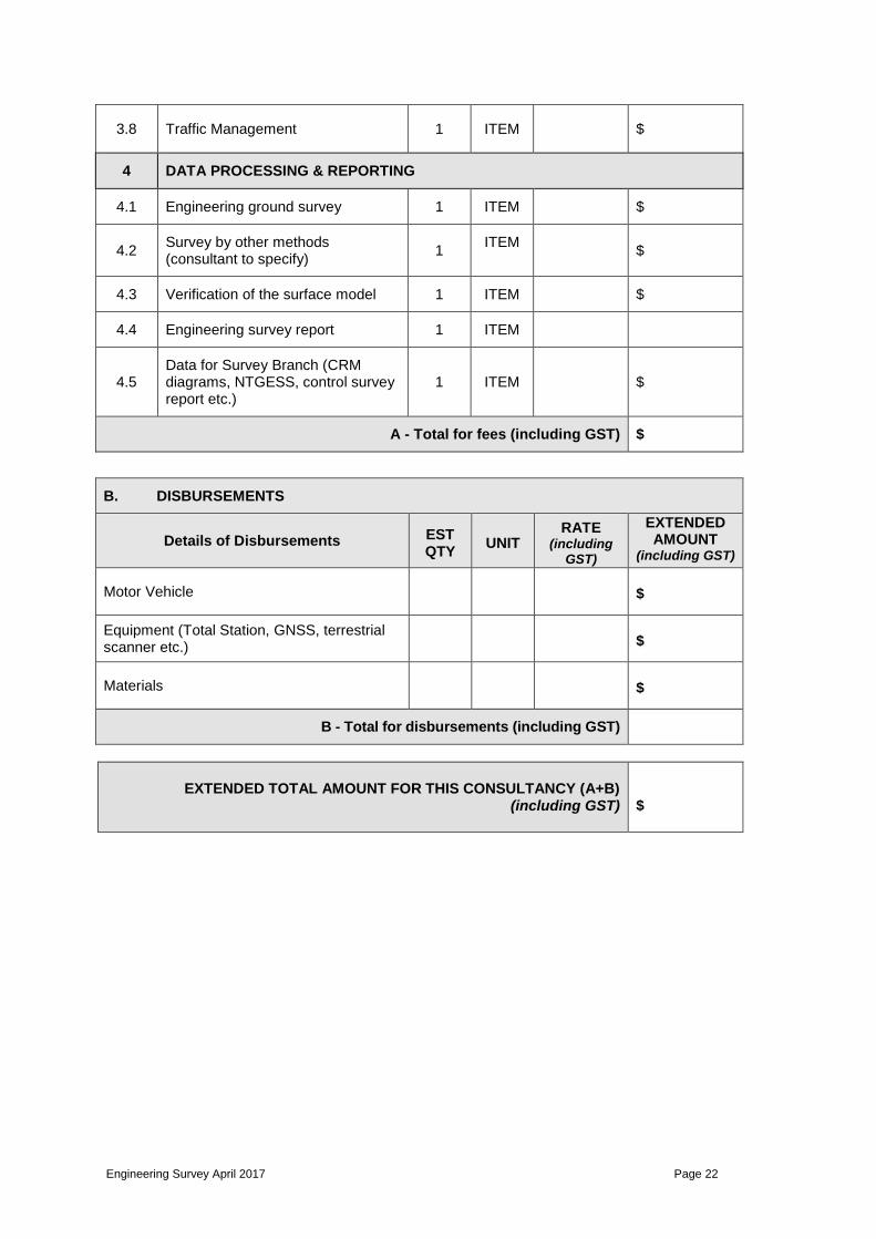
APPENDIX B PRICING SCHEDULE
The consultant’s proposal shall provide a price breakdown in sufficient detail for the Principal’s Representative to evaluate the methodology and resources proposed for delivering the project. A typical schedule is shown below:
A. FEES
ITEM DESCRIPTION EST QTY
UNIT RATE (including GST)
EXTENDED AMOUNT
(including GST)
1 PROJECT MANAGEMENT
1.1 Project establishment 1 ITEM $
1.2 Kick-off meeting 1 EACH $
1.3 Other meetings 1 EACH
1.4 Progress reports 1 EACH $
1.5 Quality control 1 ITEM $
2 PREPARATION
2.1 Data searching (control, cadastral plans, DBYD etc.)
1 ITEM $
2.2
Safety & Permits (HSE plan, Traffic Management Plan, Permit to Work on NTG road, permit to enter aboriginal land etc.)
1 ITEM $
2.3 Preparation of survey equipment, vehicle & materials
1 ITEM $
3 FIELD SURVEY
3.1 Mobilisation and Demobilisation 1 ITEM $
3.2 Survey control 1 ITEM $
3.3 Engineering ground survey 1 ITEM $
3.4 Survey by other methods (consultant to specify)
1 ITEM $
3.5 Verification of the surface model 1 ITEM $
3.6 Definition of property boundaries 1 ITEM $
3.7 Underground services locations 1 ITEM $
Engineering Survey April 2017 Page 22
3.8 Traffic Management 1 ITEM $
4 DATA PROCESSING & REPORTING
4.1 Engineering ground survey 1 ITEM $
4.2 Survey by other methods (consultant to specify)
1 ITEM
$
4.3 Verification of the surface model 1 ITEM $
4.4 Engineering survey report 1 ITEM
4.5 Data for Survey Branch (CRM diagrams, NTGESS, control survey report etc.)
1 ITEM $
A - Total for fees (including GST) $
B. DISBURSEMENTS
Details of Disbursements EST QTY
UNIT RATE
(including GST)
EXTENDED AMOUNT
(including GST)
Motor Vehicle $
Equipment (Total Station, GNSS, terrestrial scanner etc.) $
Materials $
B - Total for disbursements (including GST)
EXTENDED TOTAL AMOUNT FOR THIS CONSULTANCY (A+B) (including GST) $

Engineering Survey April 2017 Page 23
APPENDIX C AUTOCAD FILE STRUCTURE TABLE
Civil and Survey Drawing Profiles can be downloaded from the following site, along with the related Setup Instructions.
https://dipl.nt.gov.au/infrastructure/technical-records/manuals-templates