engineering standard for analytical instruments
TRANSCRIPT

IPS-E-IN-230
ENGINEERING STANDARD
FOR
ANALYTICAL INSTRUMENTS

IPS-E-IN-230
1
CONTENTS : PAGE No.
1. SCOPE ..................................................................................................................................... 3
2. REFERENCES AND SOURCES ............................................................................................. 3
2.1 References ........................................................................................................................ 3
3. GENERAL CONSIDERATIONS ............................................................................................... 4
3.1 General Design Consideration....................................................................................... 4
3.2 Analyzer Location Selection .......................................................................................... 5
4. ANALYZER INSTALLATION IN HAZARDOUS LOCATION................................................... 5
4.1 Safety Considerations ..................................................................................................... 5
4.2 Analyzer Purge Systems ................................................................................................ 6
4.3 Requirements on Instrument Enclosures..................................................................... 6
4.4 Purge Medium Supply and Disposal............................................................................ 8
4.5 Calculation of Flow Restriction Orifices...................................................................... 8
4.6 Purge Alarms .................................................................................................................... 8
4.7 Electric Interlock Requirements ..................................................................................... 8
5. ANALYZER HOUSE................................................................................................................. 8
5.1 General .............................................................................................................................. 8
5.2 Safety Consideration ....................................................................................................... 9
5.3 Location of Analyzer House.......................................................................................... 9
5.4 Dimensions of Analyzer House...................................................................................... 9
5.5 Installation Design Considerations.............................................................................. 10
5.6 Construction of Building.............................................................................................. 11
5.7 Artificial Ventilation System......................................................................................... 12
5.7.1 General requirement .............................................................................................. 12
5.7.2 Air intake system ................................................................................................... 12
5.7.3 Fan requirement ..................................................................................................... 13
5.7.4 Climatic condition .................................................................................................. 13
5.8 Utilities and Facilities ................................................................................................... 13
5.8.1 Electric power supply ........................................................................................... 13
5.8.2 Air, water and steam ............................................................................................ 14
5.8.3 Vent and drain piping systems ........................................................................... 14
5.8.4 Additional utilities .................................................................................................. 14
5.8.5 Telephone ................................................................................................................ 15
IPS-E-IN-230
2
5.8.6 Lighting .................................................................................................................... 15
5.9 Safeguarding System Through Ventilation................................................................. 15
5.10 Marking and Identification of Information................................................................ 15
5.10.1 Analyzer house nameplate .................................................................................. 15
5.10.2 Analyzer house warning notices ....................................................................... 16
5.10.3 Drain, vent and condensate systems ............................................................... 16
5.10.4 Steam supply ........................................................................................................ 16
5.10.5 Ventilation flow detection.................................................................................... 16
6. FIELD MOUNTING OF ANALYZERS................................................................................... 16
7. SAMPLE HANDLING ............................................................................................................. 17
7.1 Sample Take-Off and Transportation.......................................................................... 17
7.2 Sample Conditioning ..................................................................................................... 19
7.3 Sample Disposal System.............................................................................................. 21
8. OBLIGATIONS AND SELECTION CRITERIA FOR ANALYZERS...................................... 23
8.1 General ............................................................................................................................ 23
9. SHOP TEST AND INSPECTION.......................................................................................... 23
9.1 Building .......................................................................................................................... 23
9.2 Utilities, Drain and Vent Systems ............................................................................... 23
9.3 Heating, Ventilating and Air Conditioning (HVAC) Systems................................... 24
9.4 Equipment and Analyzer Systems............................................................................... 24
10. DRAWING AND DATA REQUIREMENTS .......................................................................... 24
APPENDICES:
APPENDIX A DIAGRAMS ...................................................................................................... 27
APPENDIX B SAMPLE CONDITIONING SYSTEM FOR SOME COMMON ANALYZERS ................................................................................. 38
APPENDIX C COMPONENTS OF THE SAMPLE CONDITIONING SYSTEM ................... 86
IPS-E-IN-230
3
1. SCOPE
The practices and requirements specified herein are some important guidelines for engineering and design of processstream analyzers used in determining the physical or chemical characteristics of petroleum and petrochemical productsapplied in Iranian Oil Industries.
Analyzers for laboratory or temporary uses are not covered herein. The recommended practices discussed should not beconsidered as substitute for expert skill and field knowledge.
All recommendations, instructions advised by manufacturers shall be submitted in the bid proposal to be considered byCompany.
2. REFERENCES AND SOURCES
2.1 References
Throughout this Standard the following standards and codes are referred to. The editions of these standards and codesthat are in effect at the time of publication of this Standard shall, to the extent specified herein, form a part of this Stan-dard . The applicability of changes in standards and codes that occur after the date of this Standard shall be mutuallyagreed upon by the Company and the Vendor:
API (AMERICAN PETROLEUM INSTITUTE)
RP-550 "Manual on Installation of Refinery Instrument and Control System, Part II Process Stream Analyzers" Sections 1 through 11 (1985)
RP-500A "Classification of Areas for Electrical Installation in Petroleum Refineries"
ANSI / ASTM (AMERICAN NATIONAL STANDARDS INSTITUTE / AMERICAN SOCIETY FOR TESTING AND MATERIALS)
D 3764 "Practice for Validation of Process Stream Analyzers" (Sec. 5.03) (1980)D 1265 "Practice for Sampling Liquified Petroleum (LP) Gases" (Sec. 5.01)D 4057 "Practice for Manual Sampling of Petroleum and Petroleum Products" (Sec. 5.03)D 4177 "Method for Automatic Sampling of Petroleum and Petroleum Products" (Sec. 5.03)F 307 "Practice for Sampling Pressurized Gas for Gas Analysis" (Sec. 10.05)
BSI (BRITISH STANDARDS INSTITUTION)
BS-476 "Fire Tests on Building Material and Structures"
ISA (INSTRUMENT SOCIETY OF AMERICA)
S7.3 "Quality Standard for Instrument Air"RP-12.6 "Installation of Intrinsically Safe Instrument Systems in Class I Hazardous Locations"S-12.4 "Instrument Purging for Reduction of Hazardous Area Classification"
NFPA (NATIONAL FIRE PROTECTION ASSOCIATION)
NFC-496 "Purged and Pressurized Enclosures for Electrical Equipment in Hazardous Locations" (1982)
Bulletin 70 National Electric Code (NEC)
IPS-E-IN-230
4
NACE (NATIONAL ASSOCIATION OF CORROSION ENGINEERS)
MR-01-75 "Sulfide Stress Cracking Resistant Metallic Material for Oil Field Equipment"
ANSI / ASTM (AMERICAN NATIONAL STANDARDS INSTITUTE / AMERICAN SOCIETY FOR TESTING AND MATERIALS)
B 31.3 "Chemical Plant and Petroleum Refinery Piping"
3. GENERAL CONSIDERATIONS
On-line process stream analyzers and their pertinent sampling systems are generally complex and expensive installa-tions, therefore the installation of on-line analyzers may be limited to the applications when the measurement of proper-ties will cause advantageous plant operation.
On-line process stream analyzer application will only be justified if they are used effectively in the following circum-stances:
a) to restrict product degradation in case of change of mode of the plant operation or when starting up;b) to control products as close as possible to the specifications in order to minimize the off-specification quality;c) to maintain high efficiency of boilers and furnaces;d) corrosion control;e) pollution control;f) personnel and plant safety.
to satisfy the above mentioned objectives, the following main requirements shall be considered in design and installa-tion of on-line process stream analyzer:
- to meet all safety requirements;- to make certain that accurate and reliable analysis to be attained;- to provide facilities for necessary testing, calibration, and isolation;- to improve on-stream time of the analyzer by proper installation design and equipment selection.
For the sake of environmental conditions preparation for preventive maintenance, adjustments and fast repairs of such acomplicated equipment and the following economical advantages:
- combined instrument cable channels;- common supply of power, water and steam;- common drain and vent lines.
Centralized analyzer houses shall be considered. Such a condition can be realized by grouping the analyzers in a wellventilated house, which forms a safe area and allows maintenance on these analyzers with the electric power switched-on.
There are, however, exceptional cases where field mounting is acceptable, for instance for analyzers which are safelyand easily serviceable on site, or transportable analyzers.
In some cases sampling conditions dictates no choice unless installation of analyzers in the field despite of all centrali-zation advantages. In such circumstances, a suitable weather protection shelter shall be considered.
3.1 General Design Consideration
The following requirements shall be considered in design of analyzer systems.
IPS-E-IN-230
5
3.1.1 All process analytical instrument readings required by the operator shall be made available in the control roomdisplay instruments.
3.1.2 The equipment, other than the manual stream selection switches and trend recorders shall be mounted on a singlerack located in the back of the main control board for the analyzers located in the main control room (if applicable).
3.1.3 Electrical wiring of instruments shall conform to IPS-E-IN-190.
3.1.4 Normally the control circuits of the analyzer should be powered from the control panel. Each analyzer shall havean overcurrent protective device (magnetic type circuit breaker or fuse). Local disconnect switches shall also be pro-vided so that the instruments can be safely serviced. Cabinet heaters, circulating pump motors and other devices whichdraw relatively high currents may be powered locally.
3.1.5 Signal wiring shall be run to the control room in separate conduit or cable. It shall be routed to the receiverinstrument by the shortest most direct route which is feasible.
3.1.6 Process control loops which include an analyzer shall normally be cascaded. In some cases where the analyzeroutput is continuous and without delay, direct control may be provided.
3.1.7 Holding circuits shall be provided when the analyzer output is used for trend recording in addition to the signalused for control loop.
3.1.8 Current to pneumatic converters shall be considered if necessary.
3.1.9 Repeater amplifiers with grounded input and floating output shall be considered when the analyzer is used inconjunction with electronic controllers.
3.2 Analyzer Location Selection
3.2.1 All analyzer components and equipment installed in process area exterior to the enclosure or analyzer house shallbe located as close as practicable to the sample point and to be provided with a roof cover to protect service personneland equipment from thundershowers, process spills, falling objects, and sunlight.
In some applications, shielding against radiant heat exposed from surrounding equipment may be provided.
3.2.2 The analyzer components shall be protected from the following substances:
- hot apparatus.- severe ambient changes.- electrical surge shock.- vibration.- mechanical shock damages.
3.2.3 The analysis cell location shall be selected in a manner to be conveniently accessible regardless of the fact that itis located at grade or some elevated point.
4. ANALYZER INSTALLATION IN HAZARDOUS LOCATION
4.1 Safety Considerations
The following minimum safety factors shall be considered in design of any analyzer installation:
4.1.1 Whether the atmosphere at analyzer location is likely to contain flammable material with explosive or ignitablemixture limit in the air, and whether this condition exists normally or only as the result of abnormal conditions, i.e.,equipment failure.
4.1.2 Whether or not it will be necessary to open the enclosures while the units are energized.
IPS-E-IN-230
6
4.1.3 Although the interior of the analyzer enclosure or house is a safe area when the ventilation system is operating,when the ventilation fails, it will be potentially hazardous area. Therefore, all equipment shall satisfy the requirementsfor Zone 2 (Division 2) areas, or the electricity supply shall be automatically switched off when the ventilation systemfails.
4.1.4 Wall sockets in analyzer houses used for electricity supply to electric tools and test equipment must be switchedoff when the ventilation system fails.
4.2 Analyzer Purge Systems
Purging is the most commonly and accepted method for reduction of explosion hazards in the vicinity of a source ofignition.
Depending on the area classification and the type of instrument, the following purge systems shall be applied.
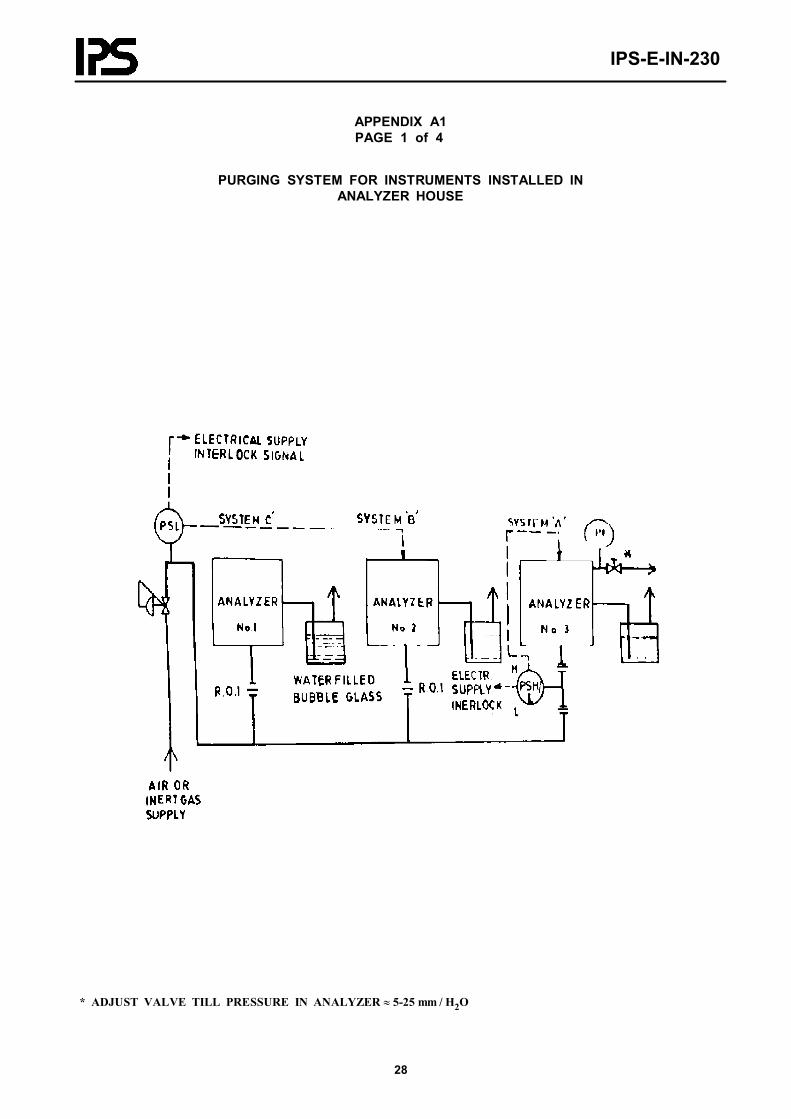
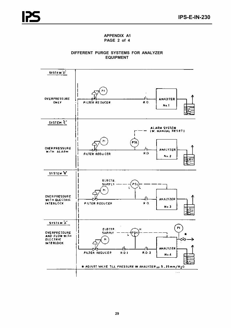
4.2.1 Purge overpressure and low flow protection with electric interlock (System A)
The purging provided in the casing of the analyzer shall be in the range of 5-25 mm-H2O, which shall normally bedetermined by the length of a dip-tube in a water filled bubble glass. The resulting small purge flow shall ensure at least5 times the flow required to dilute any leaking flammable fluids to below the LEL (Low Explosive Limit).
In compliance with the above requirements, the sample lines to the analyzer shall have engineered restrictions to limitthe flow of escaping fluid in case of seal failure.
For specific requirements on electric interlock, reference shall be made to paragraph 4.7 (refer to Appendix A1).
4.2.2 Purge system with low-pressure protection, electric interlock (System B)
For details on purging requirement, reference shall be made to System D hereunder.
For details on electric interlock refer to paragraph 4.7 (also see Appendix A1).
4.2.3 Purge system with low-pressure alarm (System C)
For details on purging requirements, refer to system D hereunder.
For details on alarm refer to paragraph 4.6 and Appendix A1.
4.2.4 Purge system only (System D)
The Purging in the casing of the analyzer shall be considered in the range of 5-25 mm-H2O, which shall normally bedetermined by the length of a dip-tube in a water filled bubble glass. The purge flow resulting by the above mentionedover-pressure shall ensure at least 10 Volume changes of the casing per hour. A restriction orifice shall be installed inthe supply line of the purge medium, (refer to Appendix A1).
4.3 Requirements on Instrument Enclosures
Process stream analyzers consist of different equipment installed in various locations in the refinery. These locations aredifferently classified according to hazardous area classifications. For area classifications the recommendations and stan-dards issued by NFPA and API shall be followed. The process stream analyzer equipment casing shall be specified tomeet the following requirements.

IPS-E-IN-230
7
4.3.1 Instruments in class 1, division 1 areas
Installing electrical instruments in class 1 Group A to D, Division 1 areas shall be avoided. Where such an installationis absolutely unavoidable, then all instrumentation shall be either.
- intrinsically safe; - purged system (see notes 1 and 2 hereunder).
Notes:
1) For non-flame-proof casing containing flammable material:
System A when air is the purge medium. System B when inert gas is the purge medium.
2) For casings not containing flammable material and for flame-proof casings containing flammable material. System B shallbe considered.
4.3.2 Instruments in class 1, division 2 areas
Instrumentations specified for installation in this area shall be either:
- intrinsically safe; - flame-proof; - purged system (see notes 1 through 3);
Ignition group of materials to be considered group A to D.
Notes:
1) For casing containing flammable material and ignition capable components, one of the following systems shall be used:
System A when the purge medium is air (see Appendix A1). System B when the purge medium is inert gas (see Appendix A1 page 2).
2) For casings containing no flammable materials but containing ignition capable components:
System B shall be employed.
3) For explosion proof casings:
System C shall be employed.
4.3.3 Instruments in safe areas
Analyzers for flammable materials generally create a Division 2 in surrounding area, even where the area is otherwisesafe. In closed shelters, the hazardous area classification shall be considered as Division 1 for analyzer installations.Purging system shall be designed in such cases to reduce the classified hazards.
Purging for analyzers on non-flammable materials, may be considered for improved protection against ambient or proc-ess conditions, System D in this application is considered to be sufficient.
4.3.4 Instruments in analyzer houses
All instruments in analyzer house shall be suitable for class 1, Group A to D, Division 2 areas.
All purged instruments shall have a low pressure alarm switch in the common purge supply line.

IPS-E-IN-230
8
In analyzer house, purging system for the house shall be provided similar to System A. In system A application foranalyzers, a high and low pressure switch shall be installed between the two restriction orifices for each instrument.Details of such design is presented in Appendix A1.
4.4 Purge Medium Supply and Disposal
Normal purge medium shall be preferably considered as instrument air.
Inert gas (normally nitrogen) shall be considered when Low Explosion Limit (LEL) is difficult to be obtained by air.
Disposal of purging gas out of casings (which contains flammable material) shall be made by means of open vent linesconducting the gas outside the analyzer house and away from places where could affect the area classification for otherequipment.
4.5 Calculation of Flow Restriction Orifices
Calculation of restriction orifices shall be based on nomogram presented in Appendix A1, page 4.
Example of application for this nomogram is presented in the same Appendix.
4.6 Purge Alarms
Failure alarm of the purge system shall be detected by a low pressure switch installed on the supply line to the analyzerand shall be indicated by visible and audible alarm in the control room for both field mounted and analyzer housemounted analyzers. The alarm shall also be indicated in analyzer house.
4.7 Electric Interlock Requirements
Purge failure shall be detected by a pressure switch (with low setting for System B and high/low settings for System A)and shall be interlocked with power switch via relay circuits. Switch-off action shall be without delay, switching back toon-state shall be activated after at least five volume changes have taken place in the casings encountered. Suitablealarms shall be considered in the interlock circuit to indicate the power supply situation of the circuit.
If automatic switch-on may damage the instruments, then a manual restart switch shall be considered in the power sup-ply line.
5. ANALYZER HOUSE
5.1 General
Analyzer house shall be totally closed premises, provided with a full redundant forced ventilation system to accommo-date analyzers. Air intake for the analyzer HVAC shall be taken from the safe area.
Analyzer house shall be located on the process area according to take-off point location of analyzers as specified inarticle 5.3 (location of analyzer houses).
An air conditioning system shall be provided for analyzer rooms in order to maintain the ambient temperature valuewithin the limits specified by analyzer vendors.
IPS-E-IN-230
9
5.2 Safety Consideration
Generally all analyzer and equipment located in analyzer house shall be suitable for at least Class I, Division 2 areasaccording to API RP-500 A and pertinent NFPA codes to be able to continue their operation under ventilation failurecondition.
The following measures shall be considered in the design of the system to provide safe conditions (non-hazardous) inthe analyzer houses.
5.2.1 Quantity of flammable materials leakage retained in the analyzer house shall be kept to a minimum.
5.2.2 Efficient ventilation system shall be provided for the houses individually to dilute any leak of flammable gasesor vapors, to reduce the concentration of air/flammable gas vapors below the Lower Explosion Limit (LEL).
5.2.3 All alternative precautions shall be considered, to make the area safe under ventilation failure condition.
5.2.4 Provision for safe disposal of samples shall be arranged.
5.2.5 Analyzer houses shall be provided with fire protection facilities.
5.3 Location of Analyzer House
The analyzer house location shall be selected in a manner to be in a non-hazardous area or in Class 1, Division 2 area inwhich a non-hazardous safe area can be found in the immediate vicinity of the area for the ventilation air inlet. It shallbe noted that the sample lines and the sample conditioning system will most likely create a Division 2 area around theanalyzer house anyhow .
The following criteria shall be considered in selecting the location of the analyzer houses:
5.3.1 The analyzer houses location shall have optimum minimized distance from the sample points of the pertinentanalyzers in a manner to minimize the sample transport time lag and cooling of the sample due to the lower ambienttemperatures.
5.3.2 The location shall be free from water and process liquids spillage.
5.3.3 The location shall be free from shock and vibrations caused by railroads, main roads traffic and process equip-ment such as compressors, etc.
5.3.4 The location shall allow free personnel evacuation in case of emergency.
5.3.5 The location shall allow free transport access of all analyzer house installed equipment and consumables, such asanalyzers, gas cylinders, tools and test equipment.
5.4 Dimensions of Analyzer House
The sizing of the analyzer house shall provide enough room for all instruments to be easily accessible on all sides foradjustments, connecting and repair activities.
Sufficient space shall be provided for a sink, work bench, terminal boxes for electrical and signal cables and all auxil-iary equipment, such as; recorders, control units, signal converters, etc.
The size of the analyzer house shall preferably be determined after making the detailed layout drawing for the best ar-rangement of all equipments to be installed in the analyzer house according to vendors recommendations.
The following criteria shall be considered in sizing the dimensions of the analyzer houses.

IPS-E-IN-230
10
5.4.1 The internal width of the house shall be selected with suitable size to allow the installation of analyzers againstopposite walls individually.
5.4.2 The internal height from ceiling to floor shall not be considered less than 2.80 meters.
5.4.3 The length shall be sized in a manner to accommodate the required number of installed analyzers and all otherrequirements stated hereafter, plus 50% spare space.
5.4.4 For preliminary estimation purpose, the average length shall be considered as 900 mm. for usual analyzers and1800 mm. for large instruments such as; process gas chromatographies, viscometers and vapor pressure analyzers.
5.4.5 Attention shall be paid to the space required on the outside walls. Space shall be reserved for the installation ofsample conditioning system on outside walls of the analyzer houses, in a manner to situate the analyzers and their perti-nent sample conditioning systems back to back located.
5.4.6 The sample conditioning space shall have a weather protection cover in a manner that the natural ventilation inthe sample conditioning area is conserved.
5.4.7 Junction boxes for signal cables should be located on outside wall against that part of the wall which sink, workbench, etc. are located opposite to sample conditioning installed wall.
5.5 Installation Design Considerations
5.5.1 Installation of analyzers
Analyzers may be either wall or rack mounted or free standing type to be installed along the two longest walls. Thefollowing requirements shall be considered in installation engineering of the analyzers layout as a minimum. (See Ap-pendix A3). However, free-standing or rack-mounted type will be prefered.
5.5.1.1 The sample conditioning equipment shall not be installed inside the building unless proper operation of thesystem obliges the inside installation.
5.5.1.2 Accessories like, fast loop system, sample recovery system, calibration and carrier gas bottles shall be installedon the external wall of the analyzer rooms.
5.5.1.3 The sample conditioning equipment shall be connected to the analyzer by either a single ¼" outer diameterstainless steel tube or by means of a secondary fast loop. (½" OD)
The flow in these lines shall be restricted by a well engineered restriction orifice, constant flow unit or a sample dosingpump.
5.5.1.4 Flow restriction shall be provided in all lines carrying hazardous materials into the house from bottles such ashydrogen carrier gas for process gas chromatographies.
5.5.1.5 The sample conditioning equipment shall be mounted on the relevant analyzer outside opposite wall of thehouse and shall be adequately weather protected.
5.5.1.6 Auxiliary instruments, such as; programmers, control units, peak holding equipment, service recorders and sig-nal converters shall be installed in small open panels, racks or on the walls in the analyzer house, with adequate purgingprovided.
These instruments shall be mounted at normal working level. These instruments shall not be mounted underneath anytype of equipment handling or using any kind of liquids.
5.5.1.7 The output signals of all analyzers shall be standard and equal to 4-20 mA or 0.2 to 1.0 bar.

IPS-E-IN-230
11
5.5.1.8 Overhead trunking shall be provided in the analyzer house for all interconnecting cables. Such a trunking shallalso be used for signal cables going from terminal boxes to the control rooms.
5.5.1.9 Gas cylinders shall be connected in pairs by means of a double needle valve for continuous and uninterruptedoperation of the analyzer. The cylinders shall be equipped with automatic cylinder change-over facility with properalarms.
5.6 Construction of Building
The following requirements shall be fulfilled in construction of analyzer houses.
5.6.1 The type of construction materials selected for construction of the analyzer house shall neither cause operationaldifficulties nor create safety hazards.
5.6.2 Floors shall be of material which can be easily cleaned from oil spills and which is acid resistance when there isa chance of spillage of chemicals used in the analyzers or in their cleaning/repair.
5.6.3 The walls of the analyzer house shall be strong enough to take the load of wall mounted analyzers and pertinentsampling system.
5.6.4 For the finish of floors, roof and walls reference shall be made to pertinent Civil Engineering Standard (G-CE-230 "Buildings and Construction Methods").
5.6.5 An acid resistant sink shall be provided complete with domestic water supply with sufficient space between sinkand tap.
5.6.6 The analyzer house drain shall be connected to the oil contaminated drain system via a corrosion resistant drainpipe and a water lock.
5.6.7 Drain pits for sample disposal shall be provided at the ends of the longest walls outside the analyzer house.
5.6.8 A small work bench shall be placed in the analyzer house as well as storage shelves or cupboards with wire meshdoors for tools and cleaning materials. Fully enclosed cupboards in which hazardous vapors or gases may accumulatemust not be used.
5.6.9 The doors shall be tight fitting, outward opening, selfclosing type.
5.6.10 The interior of the building shall be readily visible through the armored glass windows of the doors from theoutside of the analyzer house.
5.6.11 It shall be possible to open the doors from inside by means of a simple door handle or push bar only for escapepurpose in an emergency and there shall be one standard key to lock or open the doors of all analyzer houses in theplant from outside.
5.6.12 When the housing floor is concrete, it shall have a slope of 1 in 30 toward the drain located outside the housing.
5.6.13 When the housing floor is a raised open grid, it shall be in easily removable sections. The area under the houseshall be concrete as per item 5.6.12 above.
5.6.14 Free-standing analyzers shall be mounted on rigid floor support members.
5.6.15 If there is any difference in level between floor and ground, a concrete ramp shall be provided leading up toeach entrance of the house enabling wheeled equipment to enter the building conveniently. Access shall be for the fullwidth of each entrance.
5.6.16 Equipment such as gas cylinders, standard sample vessels and parts of the sample treating system which arelocated outside the housing shall be provided with a roof or shelter. Suitable racking shall be supplied for gas cylinders.
IPS-E-IN-230
12
5.6.17 Housings shall have a minimum unobstructed headroom of 2 meter and the location of the door shall be suit-able for prevailing weather conditions.
5.6.18 If a window is installed, it shall be of flame retardant wired material as defined in BS-476 Part 1.
5.6.19 The house walls and roof shall be thermally insulated to conform suitably to the environmental conditions.
5.6.20 Analyzer house shall be equipped with suitable gas and fire detection and alarming system.
5.7 Artificial Ventilation System
5.7.1 General requirement
The analyzer house shall be ventilated with air to keep out flammable and toxic gases, and any leakage of flammablegases and/or vapors which may occur inside the house shall be diluted to a safe level.
The flow of air shall be sufficient to:
- Dilute escaping vapors, resulting from the rupture or failure of any sample or service line, to less than 20% ofthe Low Explosive Limit (LEL) around any potential means of ignition.
- Maintain the pressure inside the analyzer house at 0.25 m bar above that of the outside atmosphere, to prevententry of hazardous atmosphere.
However, at least 10 volume changes per hour shall be provided to ensure adequate mixing of the internal atmosphere,or at least 20m3 of air per installed analyzer per hour, whichever is the greater in a manner to dilute any normally escap-ing flammable gas or vapor to a non-hazardous level.
The air flow shall be sufficiently turbulent to avoid dead corners which accumulation of hazardous gases may occur.
The required air flow rate shall be calculated for each analyzer house, based on the above conditions and submitted tothe Company for approval.
5.7.2 Air intake system
The air intake shall be through a stack provided with a rain-hood.
The air shall be drawn from a non-hazardous area.
The design of the intake duct and the diameter of the stack shall be sized in a manner to limit the air velocity inside theducting to 8 m/second maximally.
5.7.2.1 Air inlet and outlet openings
- The ventilation air shall enter and escape from the analyzer house via ducts and openings. Ventilation air shallenter from a safe area.
- The direction of the flow of air within the house shall ensure an air movement through and around all equip-ment installed inside the house irrespective of the wind direction and strength.
- The inlet of the air ducting shall be located at a safe distance away from any Division II area.
- Outlet openings shall be at floor and ceiling levels to allow escape of gases and vapors both heavier and lighterthan air.
- The outlets shall be flush with floor and ceiling to prevent accumulation and trapping of gases and vapors.

IPS-E-IN-230
13
5.7.2.2 Ducting
- Air shall enter and leave the analyzer house via ducting.
- The ducting material shall be of non-corrosive such as; hot-dipped galvanized steel.
- Ducts shall not run through Division I nor II areas. Inlet ducts shall be air-tight and shall be leak tight whenpassing through Division II areas.
- Filter shall be installed in the ducting such that it is easily accessible for cleaning or replacement.
- Atmospheric opening of the ducting shall be protected from rain and particulated matters irrespective of thedirection and velocity of the wind with no effect on the ventilation.
5.7.3 Fan requirement
5.7.3.1 Ventilation shall be by means of a centrifugal or axial fan driven by a directly coupled motor installed eitherinside or outside the building with suitable protection.
5.7.3.2 The type of the motors shall be suitable for Division II applications. If the motor installed inside the ducting, itshall be suitable for Division I areas, otherwise it shall be suitable for Division II areas.
5.7.3.3 The blades of the ventilator fan shall be of non-sparking material.
5.7.3.4 The power supply to the fan motor shall be independent of all analyzer house safety trip circuits.
5.7.3.5 Dual ventilation system shall be installed in houses containing analyzers which form part of a process controlsystem.
5.7.3.6 The fan support and frame construction shall be of adequate rigidity to prevent resonance and vibration.
5.7.4 Climatic condition
5.7.4.1 The temperature inside the analyzer house shall never be less than 15°C.
5.7.4.2 The maximum temperature inside the analyzer house shall be 35°C with maximum humidity of 75% unless theanalyzers or equipment used dictates lesser maximum temperature.
5.8 Utilities and Facilities
5.8.1 Electric power supply
5.8.1.1 The Electric supply shall be provided with suitable switch board panel to de-energize analyzers and pertainingelectrical equipment per analyzer and analyzer installation by dedicated switches.
5.8.1.2 Socket outlets for electric tools or test equipment shall be provided different from other circuits in the analyzerhouse. These sockets shall be interlocked on the ventilation system as specified hereunder (5.8.1.8).
5.8.1.3 The power supply distribution board shall be outside the building in the vicinity of the analyzer house door,unless otherwise specified.
5.8.1.4 The power supply to analyzers shall be 110 V ac/50 Hz or 24 V dc as specified.
5.8.1.5 All electrical equipment shall suit the area classification.
IPS-E-IN-230
14
5.8.1.6 Trunking shall be provided for the electric power supply cables to the instruments in analyzer house. Thistrunking shall be separate from the trunking for signal cables.
5.8.1.7 Electrical power cables and instrument signal cables shall enter and leave the analyzer house via separate open-ings in the floor, at one of the corners in the analyzer house.
5.8.1.8 Test equipment, electrical tools and electrical equipment without adequate protection for Division II area shallbe connected to the electricity supply via wall sockets only; the supply for which shall be automatically isolated uponventilation failure.
5.8.2 Air, water and steam
5.8.2.1 The common air supply shall be provided with a block valve, and a filter/regulator station.
5.8.2.2 PVC coated copper or S.S.316 tubing, as specified, shall be used downstream of the air filter.
5.8.2.3 The common cooling water line shall be provided with a block valve, filter and reducing station. Individualusers of cooling water shall be provided with a variable area meter and needle valve to adjust the flow.
5.8.2.4 Sweet water shall be used for cooling preferably.
5.8.2.5 Used cooling water can be piped to the waste sample drain header.
5.8.2.6 Where steam is required for analyzers, the common steam supply line must be provided with a block valve,condensate drain, and a strainer. After the strainer, copper tubing or stainless steel tubing shall be used.
5.8.3 Vent and drain piping systems
5.8.3.1 Vent and drain systems shall be installed in the conditioning area against the outside wall(s) of the analyzingpart of the house and shall be adequately supported at intervals of 1 meter maximally.
5.8.3.2 The vent and drain systems shall be selected from one of the following executions to suit the application by theCompany’s approval:
- carbon steel, all-welded construction;- stainless steel, AISI type 316, all welded construction;- rigid PVC plastic with cemented construction.
5.8.3.3 The minimum size of the piping for vent header shall be 2" (DN 50) and 3" (DN 80) for liquid drain header.The interconnecting piping shall be minimum ½" (DN 15).
5.8.3.4 Connection to drain headers without isolating valve shall be provided with a goose neck liquid seal.
A funnel and goose neck liquid seal may be installed where required.
5.8.3.5 Special attention shall be given to ensure the segregation of water and oil drain headers. Cooling water shallnot be discharged into condensate return systems.
5.8.4 Additional utilities
5.8.4.1 The following additional utilities shall be provided when specified by the Company:
- tool air; - nitrogen; - hydrogen gas (as a carrying gas); - LP steam;
IPS-E-IN-230
15
- MP steam (15 bar); - condensate supply and return lines; - sample recovery system (e.g. effluents with lead content).
5.8.4.2 All utilities shall have main shut-off valves, grouped together in the vicinity (not less than 2 meters) outsidethe analyzer house. The shut-off valves shall be clearly identified by means of yellow label.
5.8.5 Telephone
A telephone installation shall be provided inside each analyzer house. The telephones shall have type of protection Exdor Exib for use in zone 1 (Division II) areas.
5.8.6 Lighting
Adequate artificial lighting shall be provided inside and outside the analyzer house, as required for carrying out themaintenance and adjustments on complicated equipment.
Execution of the lighting fixtures and equipment shall be suitable for the area classification.
5.8.7 Automatic fire fighting system
Automatic fire fighting system shall be provided if specified in the project requirements.
5.9 Safeguarding System Through Ventilation
5.9.1 The ventilation air flow shall be measured in the suction duct by means of a venturi-tube or equivalent flowmeasuring devices to check the differential pressure to be approximately 0.25 m bar under the normal operating condi-tions. (Refer to NFPA-496, 3.3).
Venturi-tube shall be equipped with flow transmitter with a pneumatic switch in the output of the transmitter. Theswitch action shall provide the following interlock and annunciation functions:
- Audible and visible alarm in the analyzer house and in the remote control room.- Switch-off all electricity supplies to the equipment not suitable for Division II areas.
5.9.2 Doors shall be provided with "Close" position switches connected to an audible alarm in the analyzer house to besilenced by closing the door only. The doors shall be provided with automatic closing mechanism.
5.10 Marking and Identification of Information
5.10.1 Analyzer house nameplate
5.10.1.1 A nameplate indicating the analyzer room number shall be screwed to both doors of the analyzer room.
5.10.1.2 The format of the nameplate shall be in accordance with the following example:
5.10.1.3 The lettering height of the above notice shall be 25 mm. using capital letters.
ANALYZER HOUSE NUMBER AH-14
IPS-E-IN-230
16
5.10.2 Analyzer house warning notices
5.10.2.1 The following warning notice shall also be indicated on both doors of the analyzer room:
5.10.2.2 The following warning notice shall also be indicated on the separate nameplate underneath of the above men-tioned notice. The applicable statements shall be selected from those indicated here bellow:
5.10.2.3 The capital lettering height shall be 20 mm with the lower case letters to match the capital letter scale.
5.10.3 Drain, vent and condensate systems
Drain, vent and condensate system (if applicable) shall be clearly identified with nameplates and by color coding.
5.10.4 Steam supply
Nameplates shall be provided indicating the maximum pressure and temperature of the steam.
5.10.5 Ventilation flow detection
The flow detection device on the main inlet ducting shall be clearly marked (e.g. FIZ-001) and its housing shall bepainted bright red.
6. FIELD MOUNTING OF ANALYZERS
6.1 General
Field mounting of analyzers may only be considered in the following conditions:
- The cost of analyzer house is unfeasible in comparison to anticipated advantages;
- The distance of selected location of the analyzer room would result an unacceptable time lag in sample trans-portation;
- The sample is non-flammable and the mounting of the analyzer can be located in a safe area.
When the field mounting has to be performed in a dangerous area, intrinsically safe circuits for the analyzer shall beconsidered.
ANALYZER HOUSE PROTECTED BY ARTIFICIALVENTILATION
WARNING- Doors shall be kept closed- Risk of H2S- Flammable material shall not be introduced into the analyzer room without specifically permis-sion and recording.
IPS-E-IN-230
17
6.2 Weather Protection
6.2.1 The analyzer system shall be designed so that there is no dangerous emission of flammable or toxic vapors. Noliquid likely to emit such vapors shall be discharged or filled in sample containers, inside an analyzer housing.
6.2.2 When an analyzer is located in a hazardous area, the preferred installation is a cabinet or shelter substantiallyopen and free from obstruction to the free and natural passage of air. In this case, the area classification of the shel-ter/cabinet shall be same as surrounding area.
6.2.3 Field mounted analyzers shall be provided with adequate protection against adverse climatic conditions such as;rain, sun radiation, process fluids and water spills. Shielding against radiant heat from surrounding equipment (such asfurnaces) shall be provided, if necessary.
6.2.4 The analyzers may be mounted individually or in groups in analyzer cabinets or shelters.
6.2.5 In case of free ventilation obstruction, then the area classification of the interior shall be considered as Division 1and execution of the analyzers and all pertinent electrical equipment shall be selected accordingly using one of the fol-lowing technologies as may be applicable:
- intrinsically safe; - flame-proof; - purged.
6.2.6 Suitable heating shall be provided to protect the analyzer and associated sample handling equipment where nec-essary considering that even analyzers with internal thermostatically controlled heating may require heating to protectthem against external temperature according to the climatic conditions.
7. SAMPLE HANDLING
7.1 Sample Take-Off and Transportation
7.1.1 General
Sample handling systems shall be extracted such that the sample conveyed to the analyzer represents the property of theprocess material at best suited pressure, temperature, flow rate for the proper operation of the analyzer.
Basically each sample handling system consist of the following four elements:
a) sample take-off tap;b) sample transport system to the analyzer;c) sample conditioning system;d) sample return and/or sample disposal system.
Except for some analytical instruments which are designed for direct immersion of the measuring cell into the processpipe.
The design of sampling system shall be in a manner to have target time lag of 1 minute totally but in no circumstances,this time lag shall be more than 5 minutes.
7.1.2 Sample take-off tapping
7.1.2.1 Sample tappings for gaseous samples shall be taken from the top of the main line and for liquid samples fromthe side of process line .

IPS-E-IN-230
18
7.1.2.2 For liquid samples the take-off arrangement shall enable unplugging and flushing of the sample lines.
7.1.2.3 The location of the sample take-off tap shall be conveniently accessible for maintenance and inspection.
7.1.2.4 Sampling system shall be protected against plugging by means of wire mesh strainer or filters provided in theline to the analyzer.
7.1.3 Sample transportation
7.1.3.1 Normally, ¼" or ½ " stainless steel tubing shall be used for sample transportation unless other materials maybe required because of sample compositions and conditions.
7.1.3.2 Sample by-pass around the analyzers shall be provided to ensure that, the sample lines are purged and to re-duce the time lag of sampling. The sample by-pass shall be vented to atmosphere or back to a lower pressure part of theprocess for gases and shall be drained to a sewer or a lower pressure part of the process for liquids.
7.1.3.3 Heat tracing or insulation of the sample line is required if condensation of the sample can occur at ambientconditions.
7.1.3.4 Sample may be transported to the analyzer by one of the following methods:
1) Single line to the analyzer using a by-pass stream
- This system shall consist of a single line with a by-pass stream branched off close to the analyzer to maintainhigh sample transport velocity, resulting small transportation time lag.
- This system shall be used where no return point for a fast loop is available.
- In cases where liquid samples may be vaporized, the liquid is pressure reduced and completely evaporated adja-cent to the process sample take-off tap in order to reduce the by-pass stream quantity.
- The by-pass stream shall be piped to drain or vent. A sample recovery system shall be installed where eco-nomic justification permits.
- Block valves shall be provided for the system to allow maintenance of sample conditioning system.
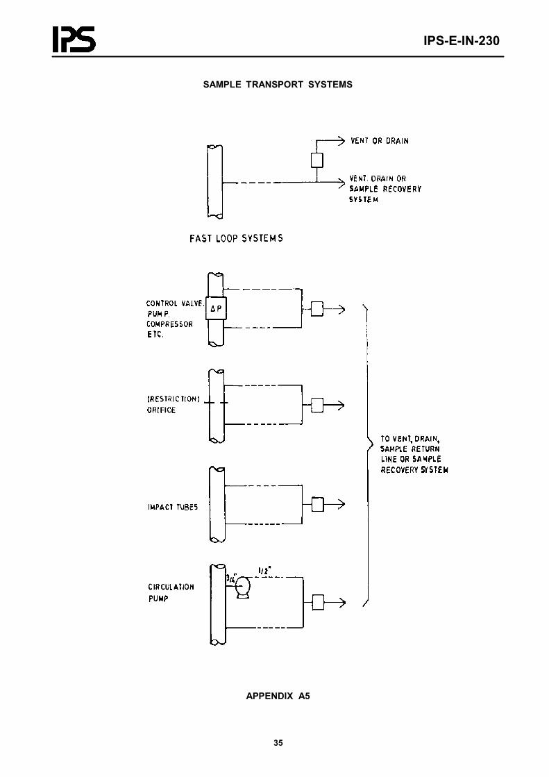
2) Fast loop system
- Fast loops shall be selected for sample transportation as the preferred solution, since there is no waste of prod-uct, the time lags are small and the piping can be arranged of reasonable size with simpler installation.
- Fast loops shall be circulating loop built over one of the following plant elements which creates differentialpressure (refer to Appendix A4):
a) Pumps with relatively constant differential pressure.
b) Control valves which produce variable differential pressure. The fast loop size shall be calculated for the differential pressure existing when the design flow is passing through the control valve in a manner that when the control valve is fully closed, the fast loop does not pass more than 10% of the design flow ofthe process pipe.
c) Process equipment which produce differential pressure depending on the particular equipment.
d) Restriction orifices with normally low relative differential pressure.
e) Impact tubes which usually produce low differential pressure. Application shall be limited to situations where no restrictions in the process line are allowable.
IPS-E-IN-230
19
- The return points of the fast loops for the analysis of gases which are sampled from the liquid phase shall bechosen such that the pressure at these points is always at least 2 barg higher than the vapor pressure of the sam-ple to prevent flashing of the product in the fast loops.
- Minimum number of joints shall be used to minimize possible leakages and to maintain the fast loop flow ashigh as possible for a given differential pressure. In performing this requirement, welding fittings shall be usedrather than screwed fittings.
- Installation of a fast loop pump shall be considered when no suitable differential pressure producing equipmentcan be found in the plant. In such a case the pump shall be installed close to the take-off tap and the suctionpiping shall be designed one size larger than the discharge piping.
- The fast loop pump performance shall be selected to guarantee a sample velocity of approximately 2 m/sec. inthe loop supply line to the analyzer in a manner that pump capacity does not exceed 10% flow of the design flowfor the pertinent process line.
- The fast loop shall be provided with block valve on fluids which may easily solidify during standstill situ-ations, a by-pass valve shall be also considered to by-pass the sample conditioning system when the system isout of operation.
7.2 Sample Conditioning
7.2.1 General
7.2.1.1 Process stream samples normally require conditioning to make them suitable for the analyzer.
7.2.1.2 The requirements set forward by the analyzer vendor shall be carefully compared with the process sample con-ditions to fulfill the operation requirements.
7.2.1.3 The general requirements for conditioning specified herein shall be considered as well as the analyzer vendorrequirements.
7.2.2 Removal of entrainments in liquids
7.2.2.1 Liquid entrainments, such as; water in oil or oil in water, shall be coalesced and further separated by means ofgravity difference methods.
7.2.2.2 Entrained gases may be separated in a similar way.
7.2.2.3 In order to prevent fouling of the coalescer packing, solids shall be removed by filteration before the coalescer.
7.2.2.4 The entrainments separated may be disposed in the return line of the fast loop system. For single line systemsan automatic drain or gas vent shall be considered.
7.2.3 Removal of entrainments in gas
7.2.3.1 Liquid or solid entrainments in the gas sample stream shall be minimized by proper selection of sample taplocation.
7.2.3.2 Separation may be obtained in the sampling system by one of the following methods, as applicable:
a) cyclone separator may be used when the sample has adequate velocity;b) by coalescing the liquid droplets and then separating by means of gravity difference method;c) filteration for solid entrainments.

IPS-E-IN-230
20
7.2.3.3 The liquid removed of gas may be disposed in the return line of the fast loop system or in an automatic drain-pot in case of a single-line system.
7.2.4 Chemical treatment and drying
7.2.4.1 When sample streams contain corrosive gases damaging the analyzer, these shall be removed by passing thesample through a liquid or a packed bed of solid chemicals.
7.2.4.2 When the sample contains moisture influencing the accuracy of the analyzer, this moisture shall be removed bymeans of chilling and trapping method. Normally desiccants shall be avoided, since, they are spent and not functioningor they may adsorb constituents other than water.
7.2.4.3 Where a liquid treating agent is applied, gas streams must be broken up in small bubbles to ensure a largeliquid to gas contact area.
7.2.4.4 In order to maintain a representative sample, the treating agent used shall not influence the property to bemeasured.
7.2.4.5 The volume of treating equipment shall be as small as possible to keep response times low. On the other handthe volume of treating or drying agent shall be large enough to remain effective for at least one week enabling thechanging of chemicals to be performed on a routine basis.
7.2.4.6 The common method of removing acid gases are application of caustic soda solution or caustic pellets. Wherethis treatment does not meet the requirements, then other technical solutions may be considered.
7.2.5 Cooling and heating
7.2.5.1 Some liquid samples may require cooling before entering the analyzers, some of which will be indicatedherein:
a) samples for initial boiling point (IBP) analyzers have to be cooled below their IBP;b) samples for flash point (FP) determination have to be cooled well below their FP;c) analysis of steam samples which are only possible when it is condensed;d) samples which require cooling to obtain separation between condensable and non-condensable vapors, i.e.flue gases sucked by a steam jet.
For the above mentioned samples, cooling system shall be provided.
7.2.5.2 For the samples which their temperature exceeds the temperature compensation range of the analyzer or wherethe temperature of the sample exceeds the capabilities of thermostated heat exchangers in the analyzer, cooling systemshall be provided. Cooling medium for analyzers shall be sweet water preferably.
7.2.5.3 Cooling by means of cold air from a vortex tube or by a mechanical refrigerant cooler shall be consideredwhere sweet cooling water is too expensive or its temperature is not low enough.
7.2.5.4 Cooling medium for samples which may solidify at temperatures lower than 100°C shall be considered as hotcondensate water. (i.e. long and short residue streams). The temperature of the condensate can be controlled by control-ling the pressure of the steam in the steam condenser.
7.2.5.5 In order to prevent condensation of gaseous samples or to lower viscosity of liquid samples, heating shall beapplied to the sample by means of either; steam, hot water or electrical tracing of the sample conditioning lines.
7.2.5.6 Necessary care shall be taken that the conditioned temperatures are maintained up to the analyzer.
IPS-E-IN-230
21
7.2.6 System for vaporization of liquid samples
7.2.6.1 Vaporizer reducer shall be provided for samples which need vaporization before they can be handled by theanalyzer.
7.2.6.2 Where the flow rate is not sufficient to prevent fractionation of the samples due to the limited turbulence in thecomparatively large volumes, then installation of a capillary tube or a tube filled with an inert packing material such assand or fire brick shall be considered on the inlet side of the vaporizer reducer.
7.2.7 Valving
7.2.7.1 Valves used in sampling systems shall have no "dead space" which will hold part of the sample material whichlater may mix with fresh sample and result erroneous results in the analysis.
7.2.7.2 Valves used for blocking purposes shall give a tight shutoff (i.e., ball or cock valve with resilient seating)especially where they are installed for stream switching.
7.2.8 Sample handling for analyzers requiring constant sample flow
Analyzers requiring constant sample flow shall be considered with one of the following three systems:
a) a restriction valve with a rotameter;b) a constant flow unit;c) a sample dosing pump.
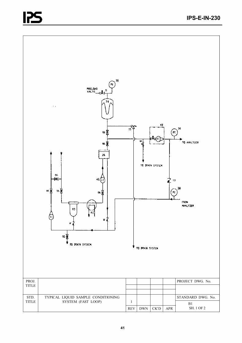
7.2.9 Typical arrangements
For typical arrangements of liquid sample conditioning system, reference to be made to Appendix B.
7.3 Sample Disposal System
7.3.1 General
7.3.1.1 Waste samples from analyzers or sample by-passes shall be returned to the process where the analyzers canoperate at process line pressure, considering economical justification.
7.3.1.2 A safe disposal of sample through drains and vents shall be provided for waste samples which cannot be re-turned to the process system because of economical considerations.
7.3.1.3 Where the waste sample is of significant value, a sample recovery vessel and pump-out facility shall be consid-ered for the system.
7.3.1.4 Where the waste sample may cause serious troubles if piped to drain (such as waxy products), or when nocontaminated drain system is available in the near vicinity, then the recovered sample may be discharged in the plantfeed line for reprocessing.
7.3.1.5 Open discharge inside analyzer houses shall be avoided especially with fluids having low flash points.
7.3.2 Vents
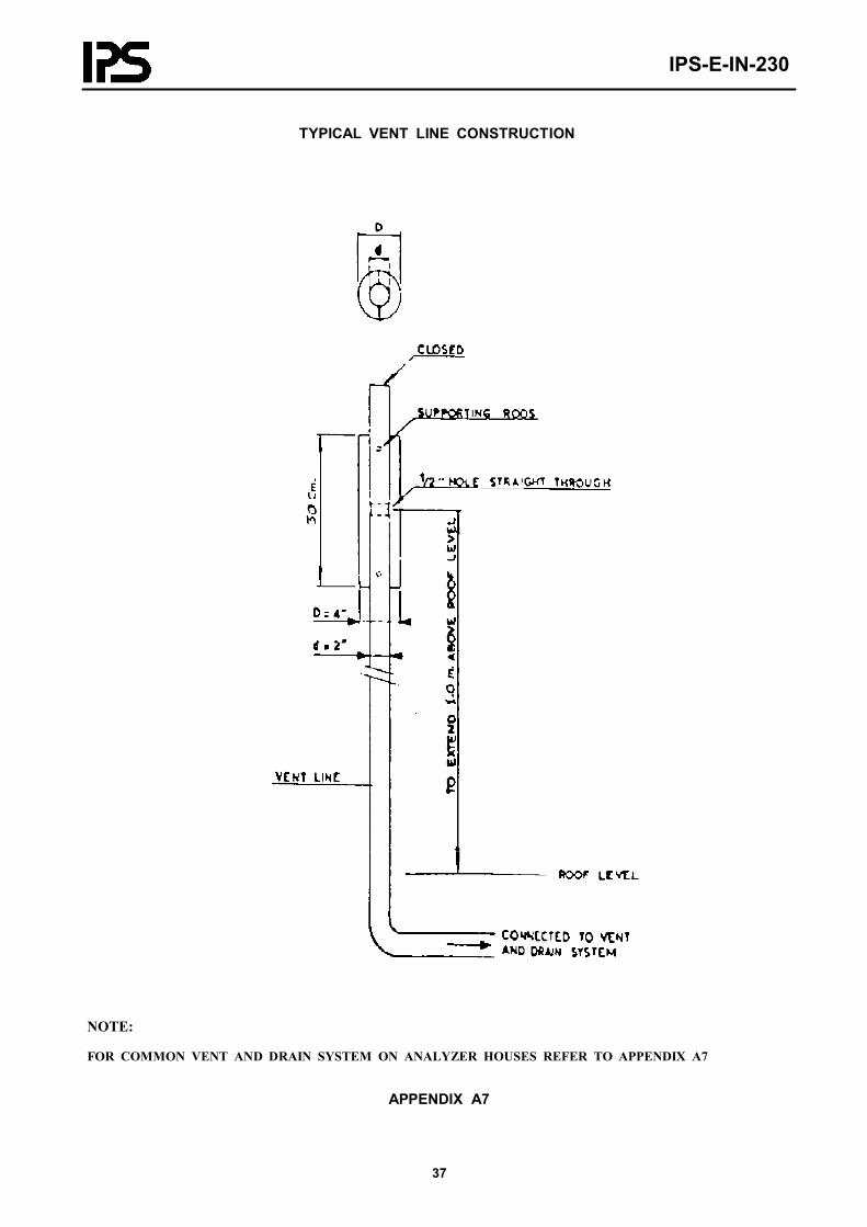
7.3.2.1 Venting of waste sample shall take place at a safe height, at least 4 meters above ground level and at least 1meter above analyzer house roof level; where the analyzer house is located in an isolated open area; or at a safe heightof 3 meters above the highest walk-way of the structure if the house is built under or close to a plant structure.
IPS-E-IN-230
22
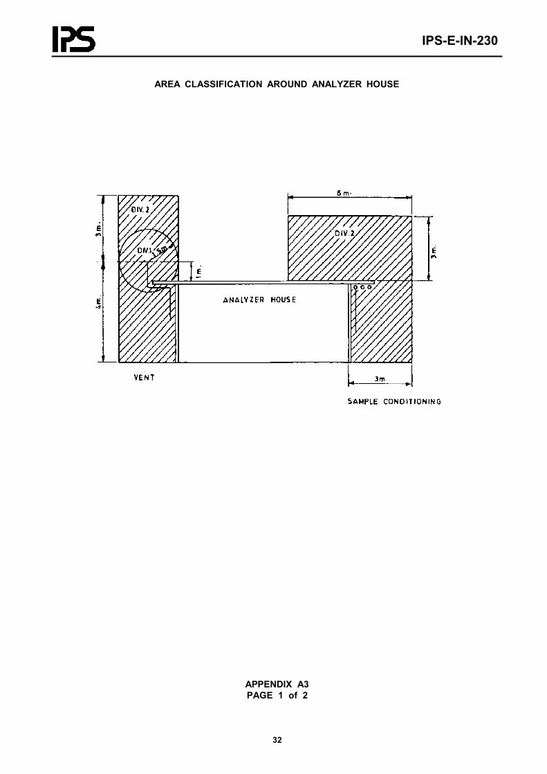
7.3.2.2 A Sphere with a radius of 1.5 meters around the vent line outlet shall be considered as a Division 1 area whilea cylinder with a radius of 1.5 meters and a height of 4 meters under and 3 meters above the outlet shall be consideredas Division 2 area, (see Appendix A2).
7.3.2.3 The vent outlet shall be located at least 1.5 meters away from any opening, i.e. doors, windows or ventilationvent holes of the analyzer house.
7.3.2.4 Special care shall be taken for venting of toxic gases in dangerous concentration.
7.3.2.5 Vent outlet shall be suitably shielded to prevent the backpressure produced by wind direction.
7.3.2.6 The vent outlet shall not be located in the air flow produced by the air cooled heat exchangers.
7.3.2.7 Provisions shall be considered to prevent liquid pockets to be formed in the vent line, if condensation of va-pors can be expected. Such condensate may be automatically drained into the drain system via a gooseneck performingas a liquid seal.
7.3.2.8 Some analyzers which are very sensitive to back-pressure influences may have an open discharge to the atmos-phere by written approval of the Company.
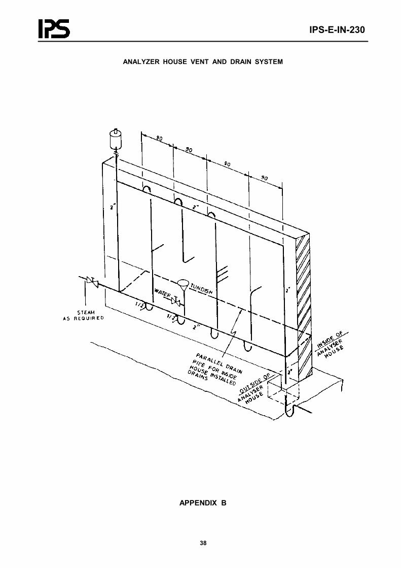
7.3.3 Drains
7.3.3.1 A Common drain line of 2 inches shall be provided along each of the two longest walls outside the analyzerhouse to discharge each individual analyzer drains into them.
7.3.3.2 The drain line shall be atmospheric and must have an atmospheric vent line at the high end, with the lower endconnected to the contaminated drain system via a liquid seal.
7.3.3.3 Tundishes shall be connected to drain line via a gooseneck liquid seal. A continuous water flow to this goose-neck shall be considered to maintain the seal when there is a possibility of continuous vent of low flash material fromthe tundish.
7.3.3.4 When it is likely that drained material will solidify in the drain system due to low temperatures (as may be thecase with waxy products) a steam heated tube has to be installed inside the drain line. (See Appendix A7 for typicaldetails).
7.3.4 Gas disposal to flare
7.3.4.1 Hydrocarbon gases or vapors which cannot be returned to the process shall be discharged to a flare system.
7.3.4.2 The effluent gas pressure shall be kept constant by means of a back-pressure regulator.
7.3.5 Liquid disposal to recovery system
7.3.5.1 Hydrocarbon liquids which cannot be returned to the process shall be discharged into one of the followingsystems:
- plant hydrocarbon recovery system, or;- drain pit for hydrocarbon products.
7.3.5.2 It shall be ensured that the total quantity of liquids disposed is limited to the minimum necessary for adequatesampling.

IPS-E-IN-230
23
7.3.6 Liquid disposal to effluent system
7.3.6.1 Aqueous fluids from analyzers using reagents shall be discharged into a dedicated effluent system used forcontaminated effluents.
8. OBLIGATIONS AND SELECTION CRITERIA FOR ANALYZERS
8.1 General
8.1.1 Suitable detectors shall be considered for alarm and necessary safety precautions where toxic gases are processedor handled which may cause intoxication dangers to personnel who have to work in these areas.
8.1.2 Reference shall be made to the plant specification for data relating to analyzers, including:
a) specification of physical and chemical conditions of sample streams;b) system requirements of accuracy, reliability and servicing frequency;c) display and output signal level information.
8.1.3 Single stream analyzers shall be used except in cases where the Company have specified or have issued a writtenagreement to multi-stream instruments.
8.1.4 The use of individual or multiple prefabricated analyzer installation should be considered in order to reduce siteinstallation work. Such a prefabrication may include sample conditioners, analyzers, air and electrical distribution, cool-ing water, water distribution or coolant circulating system piped and wired on a common frame. The design shall permittesting of the entire assembly before dispatch to site and shall be arranged for convenient removal for off-line mainte-nance.
8.1.5 A schedule of recurring maintenance and adjustment operations shall be prepared and the necessary environmentfor these operations to be specified by the Vendor and shall be provided for all analyzers purchased.
8.1.6 The measurement dead time for analyzers such as chromatograph is equal to 1.5 times of the sampling time.Therefore chromatographs can have sample times of 3 to 30 minutes, which makes them unsuitable for self regulatingloops unless the process time constant is exceptionally large (i.e., distillation column bottom product)
8.1.7 The mass spectrometer can provide an analysis in 10 to 40 seconds and should be considered for control whenthe performance of the loop is important and critical.
9. SHOP TEST AND INSPECTION
9.1 Building
9.1.1 General
Inspection and test of the building and utilities shall be performed by the civil inspectors according to pertinent civilstandards. Anyhow, the responsible assigned analyzer specialist shall be consulted on all works during the constructionof the building with special attention to the drain, vent and utility systems.
9.2 Utilities, Drain and Vent Systems
The inspection and testing of utility supplies and the drain and vent systems, shall be carried out by mechanical engi-neering in accordance with general requirements of piping standards.
IPS-E-IN-230
24
Instrument engineering shall inspect to verify the requirements set forward in this standard.
9.3 Heating, Ventilating and Air Conditioning (HVAC) Systems
The inspection and testing of HVAC systems shall be in accordance with the requirements of the pertinent standards asstated hereto:
9.4 Equipment and Analyzer Systems
9.4.1 Analyzers
9.4.1.1 The inspectors representing the Company shall have right of entry to the vendor plants including all sub-vendor’s plants where work on or testing of the equipment and instrument is being performed.
The Company reserves the right to reject individual equipment or instruments for bad workmanship or defects.
9.4.1.2 Functional test shall be performed on the analyzer system that has been warmed up and stabilized for at least24 hours.
9.4.1.3 Performance test of analyzers must be done with standard calibration gas or liquid. (where applicable)
9.4.1.4 The charts and results of final factory calibration shall be supplied as standard data sheets for the analyzer.
10. DRAWING AND DATA REQUIREMENTS
10.1 A set of drawings shall be prepared to scale by the manufacturer/supplier for all sample conditioning systemsshowing in detail:
- the correct position of components on the mounting plate;- the arrangement of the interconnections;- the method of supporting;- a list of materials required.
Typical "hook-up" drawings and examples of the requirements are given in Appendix B with list of components in Ap-pendix C .
10.2 The drawings shall be assembled in one set for each sample conditioning system, complete with cover sheet, in-dex sheet, list of materials, list of settings, technical information and where applicable, test certificates.
10.3 The manufacturer/supplier shall include an operating instruction for start-up and maintenance of the sample con-ditioning system.
10.4 The manufacturer/supplier shall send the drawings to the Company representive for comments, at least one monthbefore construction work commences.
10.5 Ten copies of the as-built drawings shall be shipped with the sample conditioning system. One set of transparentas-built drawings shall also be provided.
10.6 If the manufacturer/supplier intends to use a computerized system for the handling of components and installationmaterials, he shall obtain a written approval of the Company on the format and contents of the computer output sheets.The sheets should provide the following information minimally:
- itemized material requirements per each conditioning system;- total requirements per item;- information of material ordering.

IPS-E-IN-230
25
10.7 Complete parts list for all components and equipment used in analyzing system shall be provided to the Com-pany.

IPS-E-IN-230
26
IPS-E-IN-230
27
APPENDICES
APPENDIX ADIAGRAMS
INDEX OF APPENDICES A DIAGRAMS
A1 Purging system for instruments installed in analyzer houses 4 sheets
A2 Area Classification around analyzer house 1 sheet
A3 Typical arrangement of equipment in analyzer house 2 sheets
A4 Sample transport systems 1 sheet
A5 Typical analyzer sampling probe for line sizes 2" and above 1 sheet
A6 Typical vent line construction 1 sheet
A7 Analyzer house vent and drain system 1 sheet
IPS-E-IN-230
28
APPENDIX A1PAGE 1 of 4
PURGING SYSTEM FOR INSTRUMENTS INSTALLED INANALYZER HOUSE
* ADJUST VALVE TILL PRESSURE IN ANALYZER ≈ 5-25 mm / H2O
IPS-E-IN-230
29
APPENDIX A1PAGE 2 of 4
DIFFERENT PURGE SYSTEMS FOR ANALYZEREQUIPMENT
IPS-E-IN-230
30
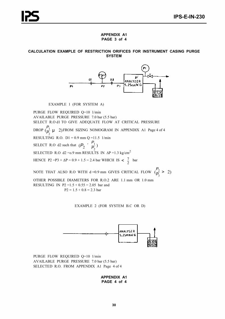
APPENDIX A1PAGE 3 of 4
CALCULATION EXAMPLE OF RESTRICTION ORIFICES FOR INSTRUMENT CASING PURGESYSTEM
EXAMPLE 1 (FOR SYSTEM A)
PURGE FLOW REQUIRED Q=10 1/minAVAILABLE PURGE PRESSURE 7.0 bar (5.5 bar)SELECT R.O d1 TO GIVE ADEQUATE FLOW AT CRITICAL PRESSURE
DROP (P1P2
µ 2) FROM SIZING NOMOGRAM IN APPENDIX A1 Page 4 of 4
RESULTING R.O. D1 = 0.9 mm Q =11.5 1/min
SELECT R.O d2 such that (P2 ´P1P2
)
SELECTED R.O d2 =o.9 mm RESULTS IN ∆P =1.3 kg/cm2
HENCE P2 =P3 + ∆P = 0.9 + 1.5 = 2.4 bar WHICH IS < 72
bar
NOTE THAT ALSO R.O WITH d =0.9 mm GIVES CRITICAL FLOW (P2P3> 2)
OTHER POSSIBLE DIAMETERS FOR R.O.2 ARE 1.1 mm OR 1.0 mmRESULTING IN P2 =1.5 + 0.55 = 2.05 bar and P2 = 1.5 + 0.8 = 2.3 bar
EXAMPLE 2 (FOR SYSTEM B.C OR D)
PURGE FLOW REQUIRED Q=10 1/minAVAILABLE PURGE PRESSURE 7.0 bar (5.5 bar)SELECTED R.O. FROM APPENDIX A1 Page 4 of 4
APPENDIX A1PAGE 4 of 4

IPS-E-IN-230
31
SIZING NOMOGRAM CONICAL ENTRANCE RESTRICTIONORIFICES FOR AIR AND NITROGEN
APPENDIX A2PAGE 1 of 1
IPS-E-IN-230
32
AREA CLASSIFICATION AROUND ANALYZER HOUSE
APPENDIX A3PAGE 1 of 2

IPS-E-IN-230
33
TYPICAL ARRANGEMENT OF EQUIPMENT IN ANALYZER HOUSE
APPENDIX A3PAGE 2 of 2

IPS-E-IN-230
34
TYPICAL ARRANGEMENT OF ANALYZER HOUSE
APPENDIX A4
IPS-E-IN-230
35
SAMPLE TRANSPORT SYSTEMS
APPENDIX A5

IPS-E-IN-230
36
TYPICAL ANALYZER SAMPLING PROBEFOR LINE SIZES NPS 2" & ABOVE
NOTES:
1 ALL MATERIALS, FLANGE TYPE, PIPE FITINGS, VALVES, CLASS RATING, BRANCH CONNECTION DE-TAILS, INSTRUMENT CONNECTION, WELDING DETAILS AND HEAT TREATMENT SHALL COMPLY WITH RELEVANT PIPING SPECIFICATIONS
2 THE PROBE SHALL NOT BE INSTALLED IN THE BOTTOM OF PROCESS LINES, TO AVOLD DIRT /WATER ENTRAINMENT IN SAMPLE.
3 THE CONTAINED VOLUME OF THE PROBE SHALL BE MINIMISED BY LIMITING THE DIMENSIONS AS GIVEN ABOVE. WHERE NECESSARY, DOUBLE VALVING SHALL BE PROBIDED. WHEN THE LIQUID SAMPLE IS TO BE VAPOURISED, DOUBLE EXTRA STRONG PIPE AND REDUCED BORE VALVE SHALLBR USED.
4 THE FLANGE SHALL BE STAMPED WITH THE PROBE TAG NUMBER AND FLOW DIRECTION.
5 THIS PROBE IS ONLY RECOMMENDED FOR SINGLE PHASE PROCESS SAMPLING.
6 FOR FAST LOOP SERVICE, THE PROBE SIZE, AND IF NECESSARY THE BRANCH CONNECTION, MAY BE INCREASED TO MEET LOOP FLOW REQUIREMENTS.
7 CARE MUST BE TAKEN WITH THE DESIGN OF THE PROBE TO ENSURE IT WILL NOT FAIL DUE TO RESONANCE EFFECTS.
APPENDIX A6
IPS-E-IN-230
37
TYPICAL VENT LINE CONSTRUCTION
NOTE:
FOR COMMON VENT AND DRAIN SYSTEM ON ANALYZER HOUSES REFER TO APPENDIX A7
APPENDIX A7
IPS-E-IN-230
38
ANALYZER HOUSE VENT AND DRAIN SYSTEM
APPENDIX B

IPS-E-IN-230
39
SAMPLE CONDITIONING SYSTEM FOR SOME COMMON ANALYZERS
INDEX OF APPENDICES B
Typical liquid sample conditioning system for;
No. of sheets
B1 - Typical sample conditioning system 2
B2 - Chromatograph-single stream 2
B3 - Chromatograph-multi stream 2
B4 - Cloud point (with cooling of sample if specified) 2
B5 - Color 2
B6 - Liquid density with cooling or flushing or both 2
B7 - Dissolved oxygen 2
B8 - Distillation (FBP and flash point) 2
B9 - Flash point with sample cooling/refrigeration 2
B10 - Kinetic vapor pressure 2
B11 - Oil in water 2
B12 - Ph and conductivity 2
B13 - Viscosity 2
B14 - Water hardness 2

IPS-E-IN-230
40
Typical gas sample conditioning system for:
No. of sheets
B15 - Chromatograph-single stream 2
B16 - Chromatograph-multi stream 2
B17 - Gas density 2
B18 - Oxygen 2
B19 - Thermal conductivity 2
B20 - Water content 2
B21 - Moisture 1
B22 - Salt-in-crude 1
B23 - Steam purity 1
B24 - N2 purity 1
B25 - Sulfur and H2S 1
IPS-E-IN-230
41
PROJECT DWG. No.PROJ.TITLE
STANDARD DWG. No.1
STD.TITLE
TYPICAL LIQUID SAMPLE CONDITIONING SYSTEM (FAST LOOP)
REV DWN CK′D APR B1
SH. 1 OF 2

IPS-E-IN-230
42
PROJECT DWG. No.PROJ.TITLE
STANDARD DWG. No.0
STD.TITLE
TYPICAL SAMPLE CONDITIONING SYSTEM FOR MULTI-STREAM SWITCHING
(SINGLE LINE USING BY-PASS STREAM) REV DWN CK′D APR B1
SH. 2 OF 2
IPS-E-IN-230
43
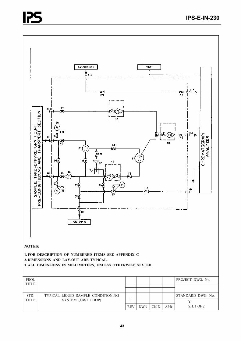
NOTES:
1. FOR DESCRIPTION OF NUMBERED ITEMS SEE APPENDIX C2. DIMENSIONS AND LAY-OUT ARE TYPICAL.3. ALL DIMENSIONS IN MILLIMETERS, UNLESS OTHERWISE STATED.
PROJECT DWG. No.PROJ.TITLE
STANDARD DWG. No.1
STD.TITLE
TYPICAL LIQUID SAMPLE CONDITIONING SYSTEM (FAST LOOP)
REV DWN CK′D APR B1
SH. 1 OF 2
IPS-E-IN-230
44
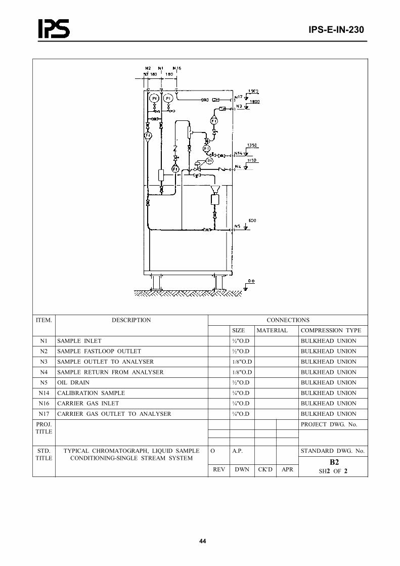
CONNECTIONSITEM. DESCRIPTION
SIZE MATERIAL COMPRESSION TYPE
N1 SAMPLE INLET ½"O.D BULKHEAD UNION
N2 SAMPLE FASTLOOP OUTLET ½"O.D BULKHEAD UNION
N3 SAMPLE OUTLET TO ANALYSER 1/8"O.D BULKHEAD UNION
N4 SAMPLE RETURN FROM ANALYSER 1/8"O.D BULKHEAD UNION
N5 OIL DRAIN ½"O.D BULKHEAD UNION
N14 CALIBRATION SAMPLE ¼"O.D BULKHEAD UNION
N16 CARRIER GAS INLET ¼"O.D BULKHEAD UNION
N17 CARRIER GAS OUTLET TO ANALYSER ¼"O.D BULKHEAD UNION
PROJECT DWG. No.PROJ.TITLE
STANDARD DWG. No.O A.P.STD.TITLE
TYPICAL CHROMATOGRAPH, LIQUID SAMPLE CONDITIONING-SINGLE STREAM SYSTEM
REV DWN CK′D APR B2
SH2 OF 2

IPS-E-IN-230
45
NOTES:
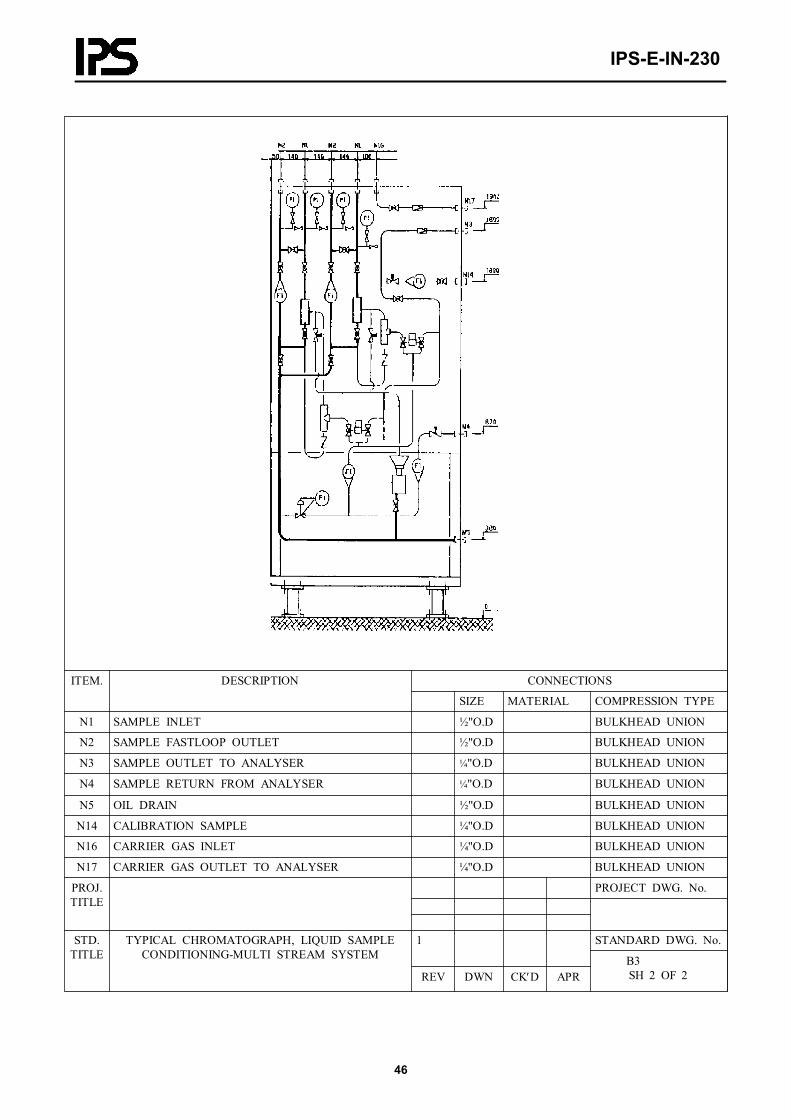
1. FOR NUMBER OF SAMPLE STREAMS SEE REQUISITION.2. TWO BALL VALVES OPERATED BY ONE PNEUMATIC ACTUATOR.3. PNEUMATIC OPERATED VALVES TO BE OPERATED BY SOLENDID VALVES FROM STREAM SELEC- TOR OF PROCESS CHROMATOGRAPH.4. FOR DESCRIPTION OF NUMBERED ITEMS SEE APPENDIX C5. DIMENSIONS AND LAY-OUT ARE TYPICAL.6. ALL DIMENSIONS IN MILLIMETERES, UNLESS OTHERWESE STATED.
PROJECT DWG. No.PROJ.TITLE
STANDARD DWG. No.1
STD.TITLE
TYPICAL CHROMATOGRAPH LIQUID SAMPLE CONDITIONING-MULTI STREAM SYSTEM
REV DWN CK′D APR B3
SH. 1 OF 2
IPS-E-IN-230
46
CONNECTIONSITEM. DESCRIPTION
SIZE MATERIAL COMPRESSION TYPE
N1 SAMPLE INLET ½"O.D BULKHEAD UNION
N2 SAMPLE FASTLOOP OUTLET ½"O.D BULKHEAD UNION
N3 SAMPLE OUTLET TO ANALYSER ¼"O.D BULKHEAD UNION
N4 SAMPLE RETURN FROM ANALYSER ¼"O.D BULKHEAD UNION
N5 OIL DRAIN ½"O.D BULKHEAD UNION
N14 CALIBRATION SAMPLE ¼"O.D BULKHEAD UNION
N16 CARRIER GAS INLET ¼"O.D BULKHEAD UNION
N17 CARRIER GAS OUTLET TO ANALYSER ¼"O.D BULKHEAD UNION
PROJECT DWG. No.PROJ.TITLE
STANDARD DWG. No.1STD.TITLE
TYPICAL CHROMATOGRAPH, LIQUID SAMPLE CONDITIONING-MULTI STREAM SYSTEM
REV DWN CK′D APR B3
SH 2 OF 2

IPS-E-IN-230
47
NOTES:
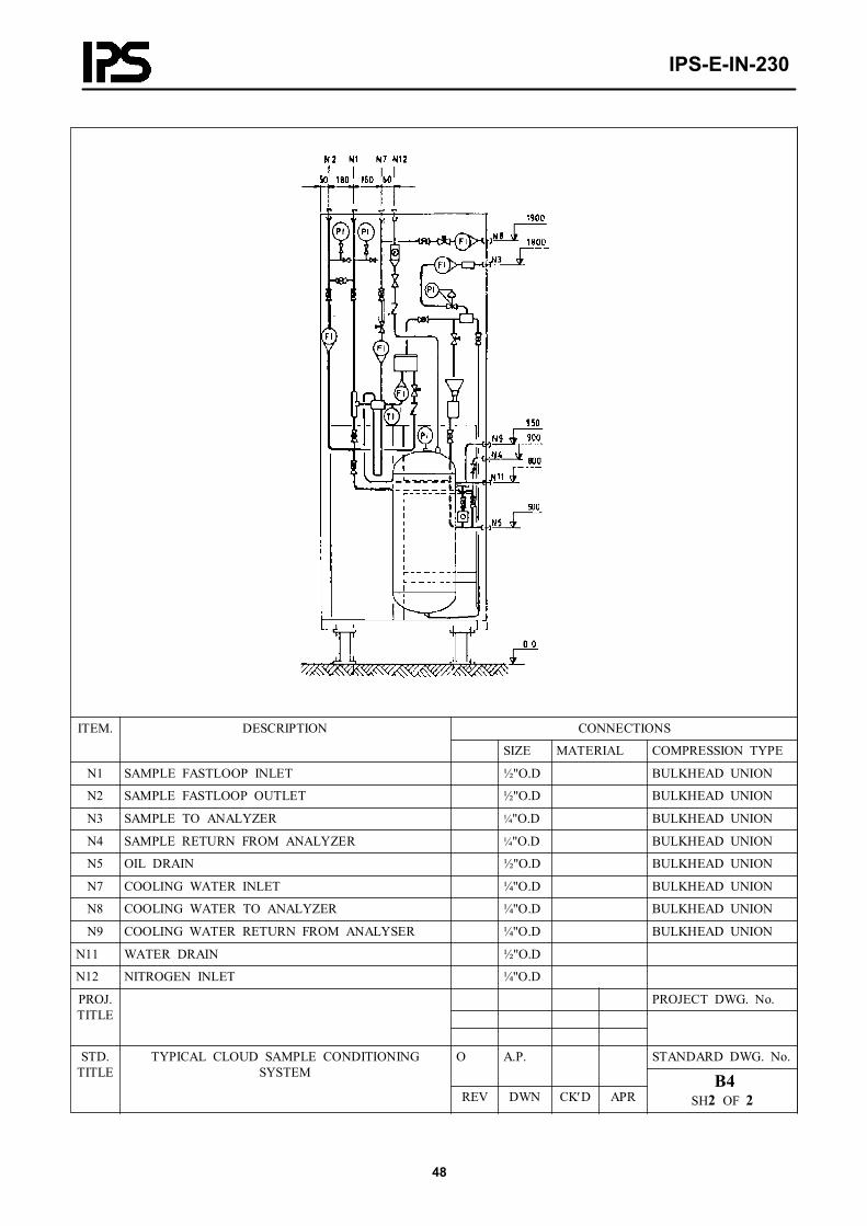
1. FOR DESCRIPTION OF NUMBERED ITEMS SEE APPENDIX C2. DIMENSIONS AND LAY-OUT ARE TYPICAL.3. ALL DIMENSIONS IN MILLIMETERS, UNLESS OTHERWISE STATED.4. SAMPLE COOLING TO BE ADDED FOR ANALYZER WITH COOLING OF SAMPLE
PROJECT DWG. No.PROJ.TITLE
STANDARD DWG. No.1
STD.TITLE
TYPICAL CLOUD POINT SAMPLE CONDITIONING SYSTEM
REV DWN CK′D APR B4
SH. 1 OF 2
IPS-E-IN-230
48
CONNECTIONSITEM. DESCRIPTION
SIZE MATERIAL COMPRESSION TYPE
N1 SAMPLE FASTLOOP INLET ½"O.D BULKHEAD UNION
N2 SAMPLE FASTLOOP OUTLET ½"O.D BULKHEAD UNION
N3 SAMPLE TO ANALYZER ¼"O.D BULKHEAD UNION
N4 SAMPLE RETURN FROM ANALYZER ¼"O.D BULKHEAD UNION
N5 OIL DRAIN ½"O.D BULKHEAD UNION
N7 COOLING WATER INLET ¼"O.D BULKHEAD UNION
N8 COOLING WATER TO ANALYZER ¼"O.D BULKHEAD UNION
N9 COOLING WATER RETURN FROM ANALYSER ¼"O.D BULKHEAD UNION
N11 WATER DRAIN ½"O.D
N12 NITROGEN INLET ¼"O.D
PROJECT DWG. No.PROJ.TITLE
STANDARD DWG. No.O A.P.STD.TITLE
TYPICAL CLOUD SAMPLE CONDITIONING SYSTEM
REV DWN CK′D APR B4
SH2 OF 2
IPS-E-IN-230
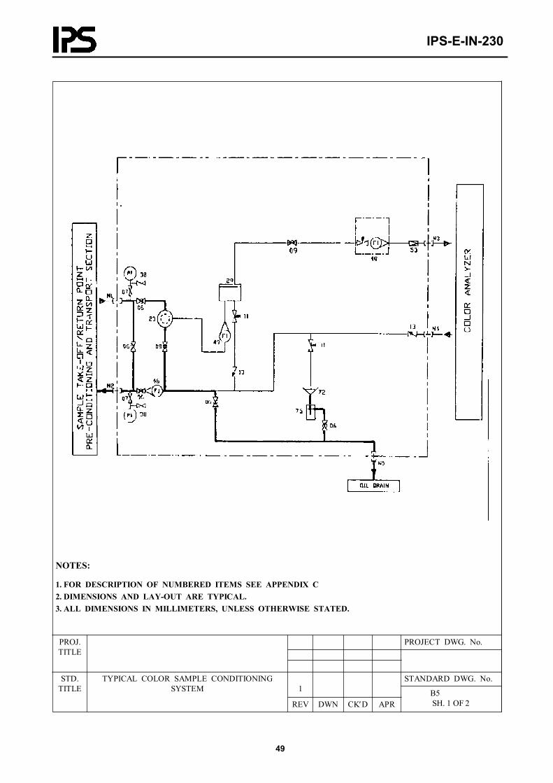
49
NOTES:
1. FOR DESCRIPTION OF NUMBERED ITEMS SEE APPENDIX C2. DIMENSIONS AND LAY-OUT ARE TYPICAL.3. ALL DIMENSIONS IN MILLIMETERS, UNLESS OTHERWISE STATED.
PROJECT DWG. No.PROJ.TITLE
STANDARD DWG. No.1
STD.TITLE
TYPICAL COLOR SAMPLE CONDITIONING SYSTEM
REV DWN CK′D APR B5
SH. 1 OF 2

IPS-E-IN-230
50
CONNECTIONSITEM. DESCRIPTION
SIZE MATERIAL COMPRESSION TYPE
N1 SAMPLE FASTLOOP INLET ½"O.D BULKHEAD UNION
N2 SAMPLE FASTLOOP OUTLET ½"O.D BULKHEAD UNION
N3 SAMPLE TO ANALYZER ¼"O.D BULKHEAD UNION
N4 SAMPLE RETURN FROM ANALYZER ¼"O.D BULKHEAD UNION
N5 OIL DRAIN ½"O.D BULKHEAD UNION
PROJECT DWG. No.PROJ.TITLE
STANDARD DWG. No.1STD.TITLE
TYPICAL COLOUR SAMPLE CONDITIONING SYSTEM
REV DWN CK′D APR B5
SH 2 OF 2

IPS-E-IN-230
51
NOTES:
1. FOR DESCRIPTION OF NUMBERED ITEMS SEE APPENDIX C2. DIMENSIONS AND LAY-OUT ARE TYPICAL.3. ALL DIMENSIONS IN MILLIMETERS, UNLESS OTHERWISE STATED.4. FLUSHING WILL BE DELETED IF NOT SPECIFIED5. COOLING WILL BE DELETED IF NOT SPECIFIED
PROJECT DWG. No.PROJ.TITLE
STANDARD DWG. No.1
STD.TITLE
TYPICAL LIQUID SAMPLE CONDITIONING SYSTEM WITH COOLING FLUSHING OR BOYH
REV DWN CK′D APR B6
SH. 1 OF 2

IPS-E-IN-230
52
CONNECTIONSITEM. DESCRIPTION
SIZE MATERIAL COMPRESSION TYPE
N1 SAMPLE FASTLOOP INLET ½"O.D BULKHEAD UNION
N2 SAMPLE FASTLOOP OUTLET ½"O.D BULKHEAD UNION
N5 OIL DRAIN ½"O.D BULKHEAD UNION
N7 COOLING WATER INLET ½"O.D BULKHEAD UNION
N11 WATER DRAIN ½"O.D BULKHEAD UNION
N13 FLUSHING OIL INLET ½"O.D BULKHEAD UNION
PROJECT DWG. No.PROJ.TITLE
STANDARD DWG. No.1STD.TITLE
TYPICAL LIQUID DENSITY SAMPLE CONDITIONING SYSTEM WITH COOLING
FLUSHING OR BOYH REV DWN CK′D APR B6
SH 2 OF 2
IPS-E-IN-230
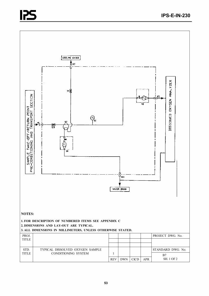
53
NOTES:
1. FOR DESCRIPTION OF NUMBERED ITEMS SEE APPENDIX C2. DIMENSIONS AND LAY-OUT ARE TYPICAL.3. ALL DIMENSIONS IN MILLIMETERS, UNLESS OTHERWISE STATED.
PROJECT DWG. No.PROJ.TITLE
STANDARD DWG. No.1
STD.TITLE
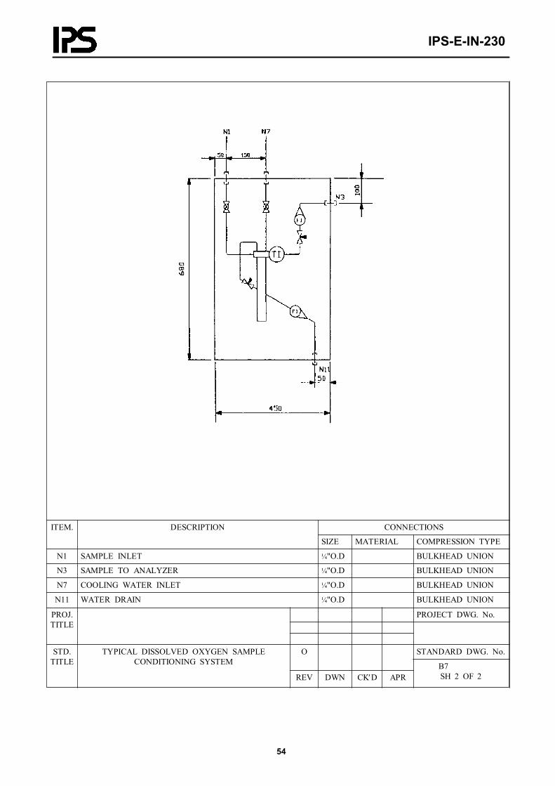
TYPICAL DISSOLVED OXYGEN SAMPLE CONDITIONING SYSTEM
REV DWN CK′D APR B7
SH. 1 OF 2
IPS-E-IN-230
54
CONNECTIONSITEM. DESCRIPTION
SIZE MATERIAL COMPRESSION TYPE
N1 SAMPLE INLET ¼"O.D BULKHEAD UNION
N3 SAMPLE TO ANALYZER ¼"O.D BULKHEAD UNION
N7 COOLING WATER INLET ¼"O.D BULKHEAD UNION
N11 WATER DRAIN ¼"O.D BULKHEAD UNION
PROJECT DWG. No.PROJ.TITLE
STANDARD DWG. No.OSTD.TITLE
TYPICAL DISSOLVED OXYGEN SAMPLE CONDITIONING SYSTEM
REV DWN CK′D APR B7
SH 2 OF 2

IPS-E-IN-230
55
NOTES:
1. FOR DESCRIPTION OF NUMBERED ITEMS SEE APPENDIX C2. DIMENSIONS AND LAY-OUT ARE TYPICAL.3. DIMENSIONS IN MILLIMETERS, UNLESS OTHERWISE STATED.4. TO BE DELETED IF COOLING OF SAMPLE IS NOT SPECIFIED
PROJECT DWG. No.PROJ.TITLE
STANDARD DWG. No.1
STD.TITLE
TYPICAL DISTILLATION (FBP, FSASH POINT) SAMPLE CONDITIONING SYSTEM
REV DWN CK′D APR B8
SH. 1 OF 2

IPS-E-IN-230
56
CONNECTIONSITEM. DESCRIPTION
SIZE MATERIAL COMPRESSION TYPE
N1 SAMPLE FASTLOOP INLET ½"O.D BULKHEAD UNION
N2 SAMPLE FASTLOOP OUTLET ½"O.D BULKHEAD UNION
N3 SAMPLE TO ANALYZER ¼"O.D BULKHEAD UNION
N4 SAMPLE RETURN FROM ANALYZER ¼"O.D BULKHEAD UNION
N5 OIL DRAIN ½"O.D BULKHEAD UNION
N7 COOLING WATER INLET ¼"O.D BULKHEAD UNION
N11 WATER DRAIN ¼"O.D BULKHEAD UNION
N12 NITROGEN INLET ¼"O.D BULKHEAD UNION
PROJECT DWG. No.PROJ.TITLE
STANDARD DWG. No.O A.P.STD.TITLE
TYPICAL DISTILLATION (FBP, FLASH POINT) SAMPLE CONDITIONING SYSTEM
REV DWN CK′D APR B8
SH2 OF 2
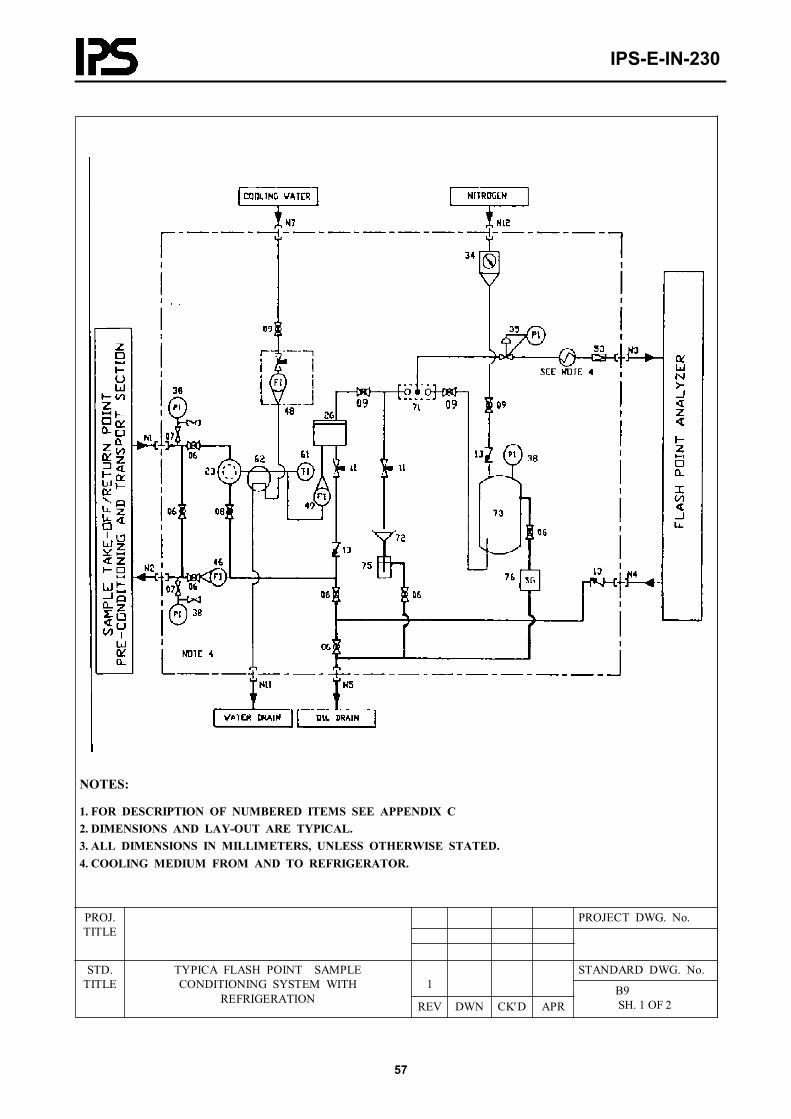
IPS-E-IN-230
57
NOTES:
1. FOR DESCRIPTION OF NUMBERED ITEMS SEE APPENDIX C2. DIMENSIONS AND LAY-OUT ARE TYPICAL.3. ALL DIMENSIONS IN MILLIMETERS, UNLESS OTHERWISE STATED.4. COOLING MEDIUM FROM AND TO REFRIGERATOR.
PROJECT DWG. No.PROJ.TITLE
STANDARD DWG. No.1
STD.TITLE
TYPICA FLASH POINT SAMPLE CONDITIONING SYSTEM WITH
REFRIGERATION REV DWN CK′D APR B9
SH. 1 OF 2
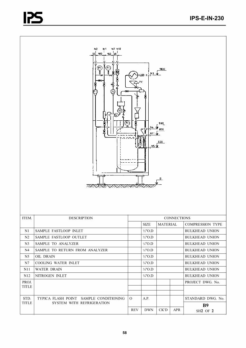
IPS-E-IN-230
58
CONNECTIONSITEM. DESCRIPTION
SIZE MATERIAL COMPRESSION TYPE
N1 SAMPLE FASTLOOP INLET ½"O.D BULKHEAD UNION
N2 SAMPLE FASTLOOP OUTLET ½"O.D BULKHEAD UNION
N3 SAMPLE TO ANALYZER ¼"O.D BULKHEAD UNION
N4 SAMPLE TO RETURN FROM ANALYZER ¼"O.D BULKHEAD UNION
N5 OIL DRAIN ½"O.D BULKHEAD UNION
N7 COOLING WATER INLET ¼"O.D BULKHEAD UNION
N11 WATER DRAIN ¼"O.D BULKHEAD UNION
N12 NITROGEN INLET ¼"O.D BULKHEAD UNION
PROJECT DWG. No.PROJ.TITLE
STANDARD DWG. No.O A.P.STD.TITLE
TYPICA FLASH POINT SAMPLE CONDITIONING SYSTEM WITH REFRIGERATION
REV DWN CK′D APR B9
SH2 OF 2

IPS-E-IN-230
59
NOTES:
1. FOR DESCRIPTION OF NUMBERED ITEMS SEE APPENDIX C2. DIMENSIONS AND LAY-OUT ARE TYPICAL.3. ALL DIMENSIONS IN MILLIMETERS, UNLESS OTHERWISE STATED.
PROJECT DWG. No.PROJ.TITLE
STANDARD DWG. No.1
STD.TITLE
TYPICAL KINETIC VAPOR PRESSURE SAMPLE CONDITIONING SYSTEM
REV DWN CK′D APR B10
SH. 1 OF 2

IPS-E-IN-230
60
CONNECTIONSITEM. DESCRIPTION
SIZE MATERIAL COMPRESSION TYPE
N1 SAMPLE FASTLOOP INLET ½"O.D BULKHEAD UNION
N2 SAMPLE FASTLOOP OUTLET ½"O.D BULKHEAD UNION
N3 SAMPLE TO ANALYZER ¼"O.D BULKHEAD UNION
N4 SAMPLE RETURN FROM ANALYZER ¼"O.D BULKHEAD UNION
N5 OIL DRAIN ½"O.D BULKHEAD UNION
N7 COOLING WATER INLET ¼"O.D BULKHEAD UNION
N8 COOLING WATER TO ANALYZER ¼"O.D BULKHEAD UNION
PROJECT DWG. No.PROJ.TITLE
STANDARD DWG. No.O A.P.STD.TITLE
TYPICAL KINETIC VAPOR PRESSURE SAMPLE CONDITIONING SYSTEM
REV DWN CK′D APR B10
SH2 OF 2
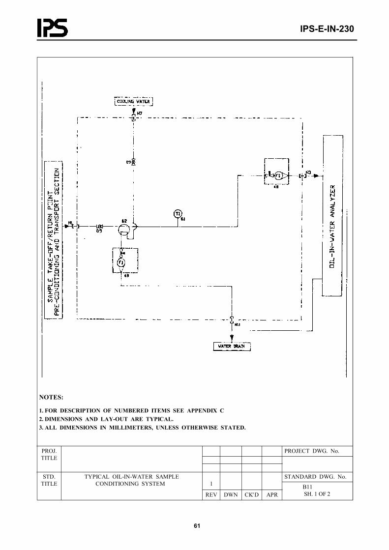
IPS-E-IN-230
61
NOTES:
1. FOR DESCRIPTION OF NUMBERED ITEMS SEE APPENDIX C2. DIMENSIONS AND LAY-OUT ARE TYPICAL.3. ALL DIMENSIONS IN MILLIMETERS, UNLESS OTHERWISE STATED.
PROJECT DWG. No.PROJ.TITLE
STANDARD DWG. No.1
STD.TITLE
TYPICAL OIL-IN-WATER SAMPLE CONDITIONING SYSTEM
REV DWN CK′D APR B11
SH. 1 OF 2

IPS-E-IN-230
62
CONNECTIONSITEM. DESCRIPTION
SIZE MATERIAL COMPRESSION TYPE
N1 SAMPLE INLET ¼"O.D BULKHEAD UNION
N3 SAMPLE TO ANALYZER ¼"O.D BULKHEAD UNION
N7 COOLING WATER INLET ¼"O.D BULKHEAD UNION
N11 WATER DRAIN ¼"O.D BULKHEAD UNION
PROJECT DWG. No.PROJ.TITLE
STANDARD DWG. No.1STD.TITLE
TYPICAL OIL-IN-WATER SAMPLE CONDITIONING SYSTEM
REV DWN CK′D APR B11
SH 2 OF 2

IPS-E-IN-230
63
NOTES:
1. FOR TYPE MEASURING CELL SEE REQUISITION AND RELEVENT DRAWING OF ANALYZER FLOW CELL TO BE INSTALLED BELOW INLET AND OUTLET LINE LEVEL TO MAINTAIN LIQUID IN CELL. FLOW CELL TO BE INSTALLED SO THAT CAS SCAVENGING IS ASSURED.2. SPEC FOR TRANSMITTER AND LOCAL INDICATOR IFREQUIRED SHALL BE PROVIDED 3. FOR DESCRIPTION OF NUMBERED ITEMS SEE APPENDIX C4. DIMENSIONS AND LAY-OUT ARE TYPICAL5. ALL DIMENSIONS IN MILLIMETERS, UNLESS OTHERWISE STATED.6. DELETED IF SPECIFIED WITHOUT FILTER / COALESCER. 7. COOLING WATER SHALL BE ADDED, IF REQUIRED.
PROJECT DWG. No.PROJ.TITLE
STANDARD DWG. No.1
STD.TITLE
TYPICAL PH. CONDUCTIVITY SAMPLE CONDITIONING SYSTEM
REV DWN CK′D APR B12
SH. 1 OF 2

IPS-E-IN-230
64
CONNECTIONSITEM. DESCRIPTION
SIZE MATERIAL COMPRESSION TYPE
N1 SAMPLE INLET ¼"O.D BULKHEAD UNION
N11 WATER DEAIN ½"O.D BULKHEAD UNION
N7 COOLING WATER INLET ¼"O.D BULKHEAD UNION
PROJECT DWG. No.PROJ.TITLE
STANDARD DWG. No.1STD.TITLE
TYPICAL PH, CONDUCTIVITY SAMPLE CONDITIONING SYSTEM
REV DWN CK′D APR B12
SH 2 OF 2

IPS-E-IN-230
65
NOTES:
1. CALIBRATION VESSEL TO BE PROVIDED WITH EXTERNAL HEATING2. FOR DESCRIPTION OF NUMBERED ITEMS SEE APPENDIX C3. DIMENSIONS AND LAY-OUT ARE TYPICAL.4. ALL DIMENSIONS IN MILLIMETERS, UNLESS OTHERWISE STATED.
PROJECT DWG. No.PROJ.TITLE
STANDARD DWG. No.1
STD.TITLE
TYPICAL VISCOSITY SAMPLE CONDITIONING SYSTEM
REV DWN CK′D APR B13
SH. 1 OF 2
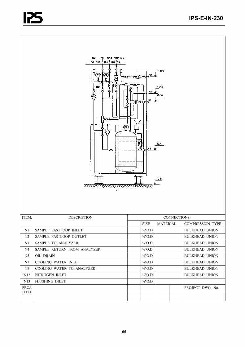
IPS-E-IN-230
66
CONNECTIONSITEM. DESCRIPTION
SIZE MATERIAL COMPRESSION TYPE
N1 SAMPLE FASTLOOP INLET ½"O.D BULKHEAD UNION
N2 SAMPLE FASTLOOP OUTLET ½"O.D BULKHEAD UNION
N3 SAMPLE TO ANALYZER ¼"O.D BULKHEAD UNION
N4 SAMPLE RETURN FROM ANALYZER ¼"O.D BULKHEAD UNION
N5 OIL DRAIN ½"O.D BULKHEAD UNION
N7 COOLING WATER INLET ¼"O.D BULKHEAD UNION
N8 COOLING WATER TO ANALYZER ¼"O.D BULKHEAD UNION
N12 NITROGEN INLET ¼"O.D BULKHEAD UNION
N13 FLUSHING INLET ½"O.D
PROJECT DWG. No.PROJ.TITLE
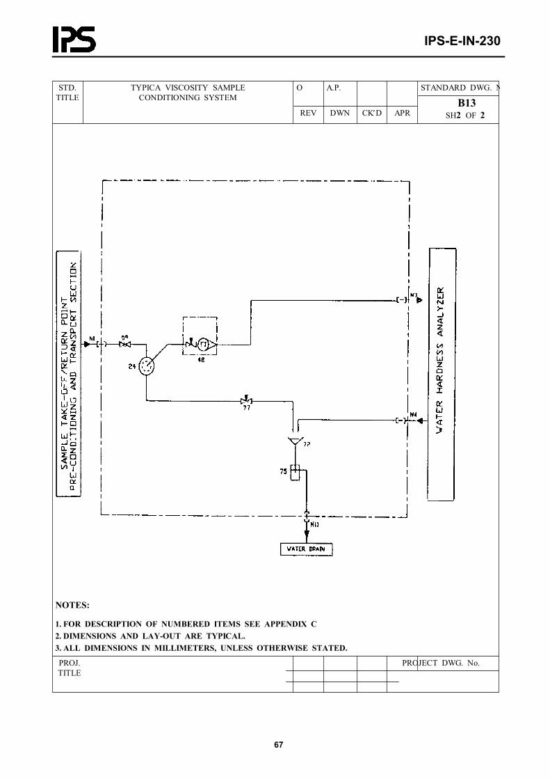
IPS-E-IN-230
67
STANDARD DWG. NO A.P.STD.TITLE
TYPICA VISCOSITY SAMPLECONDITIONING SYSTEM
REV DWN CK′D APR B13
SH2 OF 2
NOTES:
1. FOR DESCRIPTION OF NUMBERED ITEMS SEE APPENDIX C2. DIMENSIONS AND LAY-OUT ARE TYPICAL.3. ALL DIMENSIONS IN MILLIMETERS, UNLESS OTHERWISE STATED.
PROJECT DWG. No.PROJ.TITLE
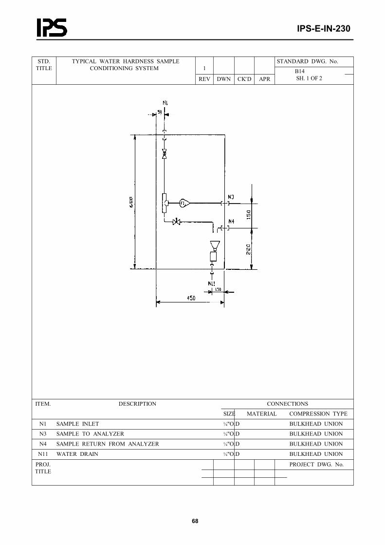
IPS-E-IN-230
68
STANDARD DWG. No.1
STD.TITLE
TYPICAL WATER HARDNESS SAMPLE CONDITIONING SYSTEM
REV DWN CK′D APR B14
SH. 1 OF 2
CONNECTIONSITEM. DESCRIPTION
SIZE MATERIAL COMPRESSION TYPE
N1 SAMPLE INLET ¼"O.D BULKHEAD UNION
N3 SAMPLE TO ANALYZER ¼"O.D BULKHEAD UNION
N4 SAMPLE RETURN FROM ANALYZER ¼"O.D BULKHEAD UNION
N11 WATER DRAIN ¼"O.D BULKHEAD UNION
PROJECT DWG. No.PROJ.TITLE
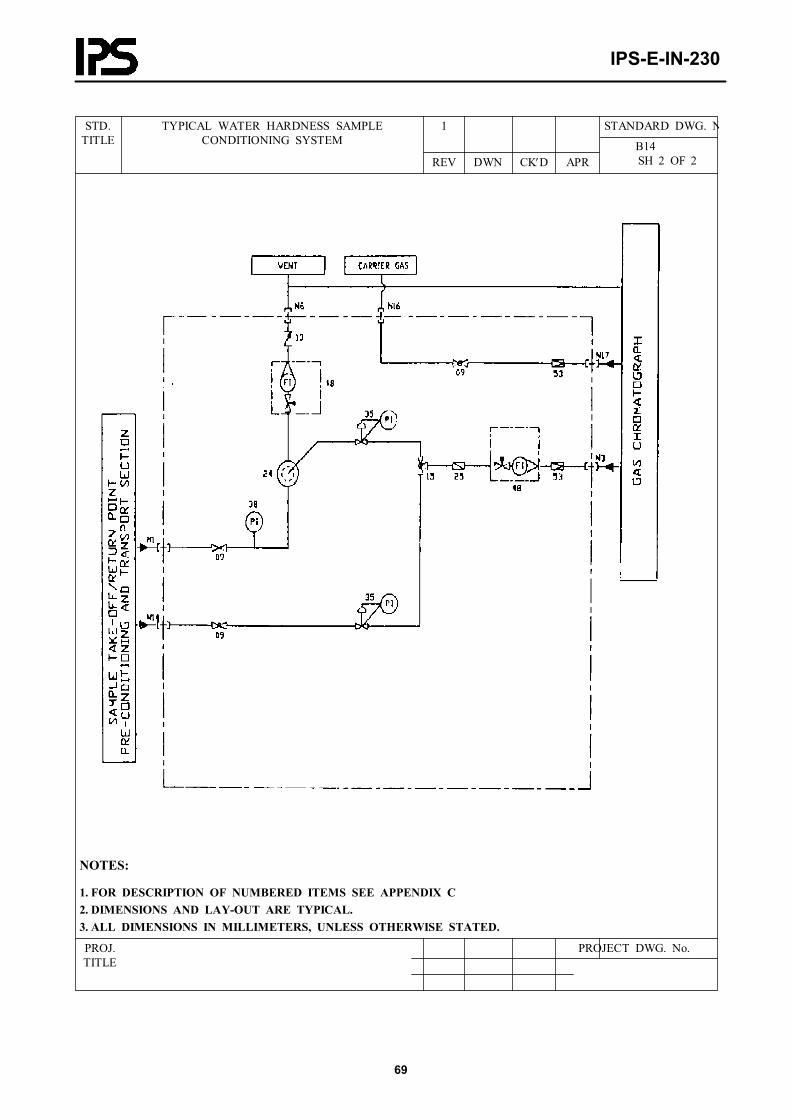
IPS-E-IN-230
69
STANDARD DWG. N1STD.TITLE
TYPICAL WATER HARDNESS SAMPLE CONDITIONING SYSTEM
REV DWN CK′D APR B14
SH 2 OF 2
NOTES:
1. FOR DESCRIPTION OF NUMBERED ITEMS SEE APPENDIX C2. DIMENSIONS AND LAY-OUT ARE TYPICAL.3. ALL DIMENSIONS IN MILLIMETERS, UNLESS OTHERWISE STATED.
PROJECT DWG. No.PROJ.TITLE

IPS-E-IN-230
70
STANDARD DWG. No.1
STD.TITLE
TYPICAL CHROMATOGRAPH-GAS SAMPLE CONDITIONING SYSTEM - SINGLE STREAM
REV DWN CK′D APR B15
SH. 1 OF 2
CONNECTIONSITEM. DESCRIPTION
SIZE MATERIAL COMPRESSION TYPE
N1 SAMPLE INLET ¼"O.D BULKHEAD UNION
N3 SAMPLE TO ANALYZER 1/8"O.D BULKHEAD UNION
N6 SAMPLE TO VENT ¼"O.D BULKHEAD UNION
N14 CALIBRATION SAMPLE INLET ¼"O.D BULKHEAD UNION
N16 CARRIER GAS INLET ¼"O.D BULKHEAD UNION
N17 CARRIER GAS ANALYZER ¼"O.D BULKHEAD UNION
PROJECT DWG. No.PROJ.TITLE

IPS-E-IN-230
71
STANDARD DWG. No1STD.TITLE
TYPICAL CHROMATOGRAPH-GAS SAMPLE CONDITIONING SYSTEM-SINGLE STREAM
REV DWN CK′D APR B15
SH2 OF 2
NOTES:
1. FOR UNMBER OF SAMPLE STREAMS, SEE REQUISITION.2. PNEUMATIC OPERATED VALVES TO BE CONTROLLED BY PROCESS CHROMATOGRAPH, STREAM SELECTOR VIA SOLENDID VALVES.3. FOR DESCRIPTION OF NUMBERED ITEMS SEE APPENDIX C4. DIMENSIONS AND LAY-OUT ARE TYPICAL5. ALL DIMENSIONS IN MILLIMETERS, UNLESS OTHERWISE STATED.6. TWO BALL VALVES OPERATED BY ONE PNEUMATIC ACTUATOR.
PROJECT DWG. No.PROJ.TITLE

IPS-E-IN-230
72
STANDARD DWG. No.1
STD.TITLE
TYPICAL CHROMATOGRAPH LIQUID SAMPLE CONDITIONING-MULTI STREAM STREAM
REV DWN CK′D APR B16
SH. 1 OF 2
CONNECTIONSITEM. DESCRIPTION
SIZE MATERIAL COMPRESSION TYPE
N1 SAMPLE INLET ¼"O.D BULKHEAD UNION
N3 SAMPLE TO ANALYZER 1/8"O.D BULKHEAD UNION
N6 SAMPLE TO VENT ¼"O.D BULKHEAD UNION
N14 CALIBRATION SAMPLE INLET ¼"O.D BULKHEAD UNION
N16 CARRIER GAS INLET ¼"O.D BULKHEAD UNION
N17 CARRIER GAS ANALYZER ¼"O.D BULKHEAD UNION
PROJECT DWG. No.PROJ.TITLE

IPS-E-IN-230
73
STANDARD DWG. N0 A.P.STD.TITLE
TYPICAL CHROMATOGRAPH-GAS SAMPLE CONDITIONING SYSTEM MULTI STREAM
REV DWN CK′D APR B16
SH2 OF 2
NOTES:
1. FOR DESCRIPTION OF NUMBERED ITEMS SEE APPENDIX C2. DIMENSIONS AND LAY-OUT ARE TYPICAL.3. ALL DIMENSIONS IN MILLIMETERS, UNLESS OTHERWISE STATED.
PROJECT DWG. No.PROJ.TITLE

IPS-E-IN-230
74
STANDARD DWG. No.1
STD.TITLE
TYPICAL DENSITY-GAS SAMPLE CONDITIONING SYSTEM
REV DWN CK′D APR B17
SH. 1 OF 2
CONNECTIONSITEM. DESCRIPTION
SIZE MATERIAL COMPRESSION TYPE
N1 SAMPLE INLET ¼"O.D BULKHEAD UNION
N3 SAMPLE TO ANALYZER ¼"O.D BULKHEAD UNION
N6 SAMPLE TO VENT ¼"O.D BULKHEAD UNION
N14 CALIBRATION GAS INLET ¼"O.D BULKHEAD UNION
PROJECT DWG. No.PROJ.TITLE

IPS-E-IN-230
75
STANDARD DWG. N1STD.TITLE
TYPICAL DENSITY-GAS SAMPLE CONDITIONING SYSTEM
REV DWN CK′D APR B17
SH 2 OF 2
NOTES:
1. FOR DESCRIPTION OF NUMBERED ITEMS SEE APPENDIX C2. DIMENSIONS AND LAY-OUT ARE TYPICAL.3. ALL DIMENSIONS IN MILLIMETERS, UNLESS OTHERWISE STATED.
PROJECT DWG. No.PROJ.TITLE

IPS-E-IN-230
76
STANDARD DWG. No.1
STD.TITLE
TYPICAL OXYGEN SAMPLE CONDITIONING SYSTEM
REV DWN CK′D APR B18
SH. 1 OF 2
CONNECTIONSITEM. DESCRIPTION
SIZE MATERIAL COMPRESSION TYPE
N1 SAMPLE INLET ¼"O.D BULKHEAD UNION
N3 SAMPLE TO ANALYZER ¼"O.D BULKHEAD UNION
N6 SAMPLE TO VENT ¼"O.D BULKHEAD UNION
N12 NITROGEN INLET ¼"O.D BULKHEAD UNION
N14 CALIBRATION SAMPLE INLET ¼"O.D BULKHEAD UNION
N15 INSTRUMENT AIR INLET ¼"O.D
N17 CALIBRATION GAS TO ANALYZER ¼"O.D BULKHEAD UNION
PROJECT DWG. No.PROJ.TITLE
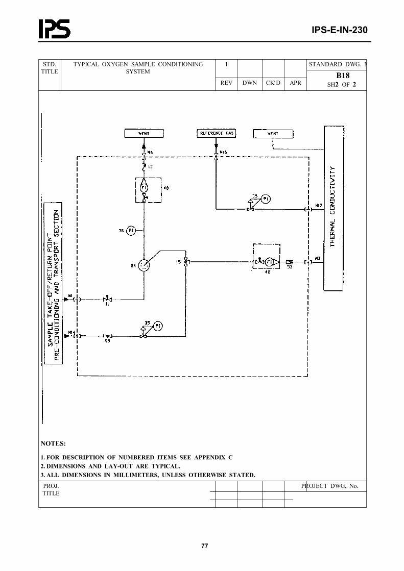
IPS-E-IN-230
77
STANDARD DWG. N1STD.TITLE
TYPICAL OXYGEN SAMPLE CONDITIONING SYSTEM
REV DWN CK′D APR B18
SH2 OF 2
NOTES:
1. FOR DESCRIPTION OF NUMBERED ITEMS SEE APPENDIX C2. DIMENSIONS AND LAY-OUT ARE TYPICAL.3. ALL DIMENSIONS IN MILLIMETERS, UNLESS OTHERWISE STATED.
PROJECT DWG. No.PROJ.TITLE

IPS-E-IN-230
78
STANDARD DWG. No.1
STD.TITLE
TYPICAL THERMAL CONDUCTIVITY SAMPLE CONDITIONING SYSTEM
REV DWN CK′D APR B19
SH. 1 OF 2
CONNECTIONSITEM. DESCRIPTION
SIZE MATERIAL COMPRESSION TYPE
N1 SAMPLE INLET ¼"O.D BULKHEAD UNION
N3 SAMPLE TO ANALYZER ¼"O.D BULKHEAD UNION
N6 SAMPLE TO VENT ¼"O.D BULKHEAD UNION
N14 CALIBRATION SAMPLE INLET ¼"O.D BULKHEAD UNION
N16 REFERENCE GAS INLET ¼"O.D
N17 REFERENC GAS TO ANALYZER ¼"O.D BULKHEAD UNION
PROJECT DWG. No.PROJ.TITLE

IPS-E-IN-230
79
STANDARD DWG. N0 A.P.STD.TITLE
TYPICAL THERMAL CONDUCTIVITY SAMPLE CONDITIONING SYSTEM
REV DWN CK′D APR B19
SH2 OF 2
NOTES:
1. COIL LENGTH TO BE MINIMUM 5 METERS.2. FOR DESCRIPTION OF NUMBERED ITEMS SEE APPENDIX C3. DIMENSIONS AND LAY-OUT ARE TYPICAL.4. ALL DIMENSIONS IN MILLIMETERS, UNLESS OTHERWISE STATED.
PROJECT DWG. No.PROJ.TITLE

IPS-E-IN-230
80
STANDARD DWG. No.1
STD.TITLE
TYPICAL WATER CONTENT SAMPLE CONDITIONING SYSTEM
REV DWN CK′D APR B20
SH. 1 OF 2
CONNECTIONSITEM. DESCRIPTION
SIZE MATERIAL COMPRESSION TYPE
N1 SAMPLE INLET ¼"O.D BULKHEAD UNION
N3 SAMPLE TO ANALYZER ¼"O.D BULKHEAD UNION
N6 SAMPLE TO VENT ¼"O.D BULKHEAD UNION
PROJECT DWG. No.PROJ.TITLE

IPS-E-IN-230
81
STANDARD DWG. No.0 A.P.STD.TITLE
TYPICAL WATER CONTENT SAMPLE CONDITIONING SYSTEM
REV DWN CK′D APR B20
SH 2 OF 2
CONNECTIONSITEM. DESCRIPTION
SIZE MATERIAL COMPRESSION TYPE
N1 SAMPLE INLET ½"O.D BULKHEAD UNION
N3 SAMPLE TO ANALYZER ¼"O.D BULKHEAD UNION
N5 OUTLET FROM ANALYZER ¼"O.D BULKHEAD UNION
N6 SAMPLE VENT TO ATMOSPHERE ½"O.D BULKHEAD UNION
PROJECT DWG. No.PROJ.TITLE

IPS-E-IN-230
82
STANDARD DWG. No1STD.TITLE
TYPICAL MOISTURE SAMPLE CONDITIONING SYSTEM
REV DWN CK′D APR B21
SH2 OF 2
NOTES:
1. ALL TUBING & FITTINGS IN CONTACT WITH FLUIDS MUST BE OF STAINLESS STELL2. CALIBRATION VESSELS SHALL BE REMOVABLE FOR LAB FILLING OR ANALYSIS.3. N1 = CRUDE IN, N2 = CRUDE OUT, N3 = SPENT SAMPLE RETURN, SHALL BE ¾" PIPING4. N4 = CRUDE TO ANALYZER, N5 = CRUDE OUT OF ANALYZER, N7 = NITROGEN TO ANALYZER, SHALL BE ¼" S.S. COMPRESSION BULKHEAD UNIONS.5. N8 = NITROGEN IN, N9 = INSTRUMENT AIR IN, SHALL BE ¼" S.S. COMPRESSION BULKHEAD UNIONS.6. N10 = VENT, SHALL BE ¼" BULKHEAD UNION, COMPRESSION FITTING.
PROJECT DWG. No.PROJ.TITLE
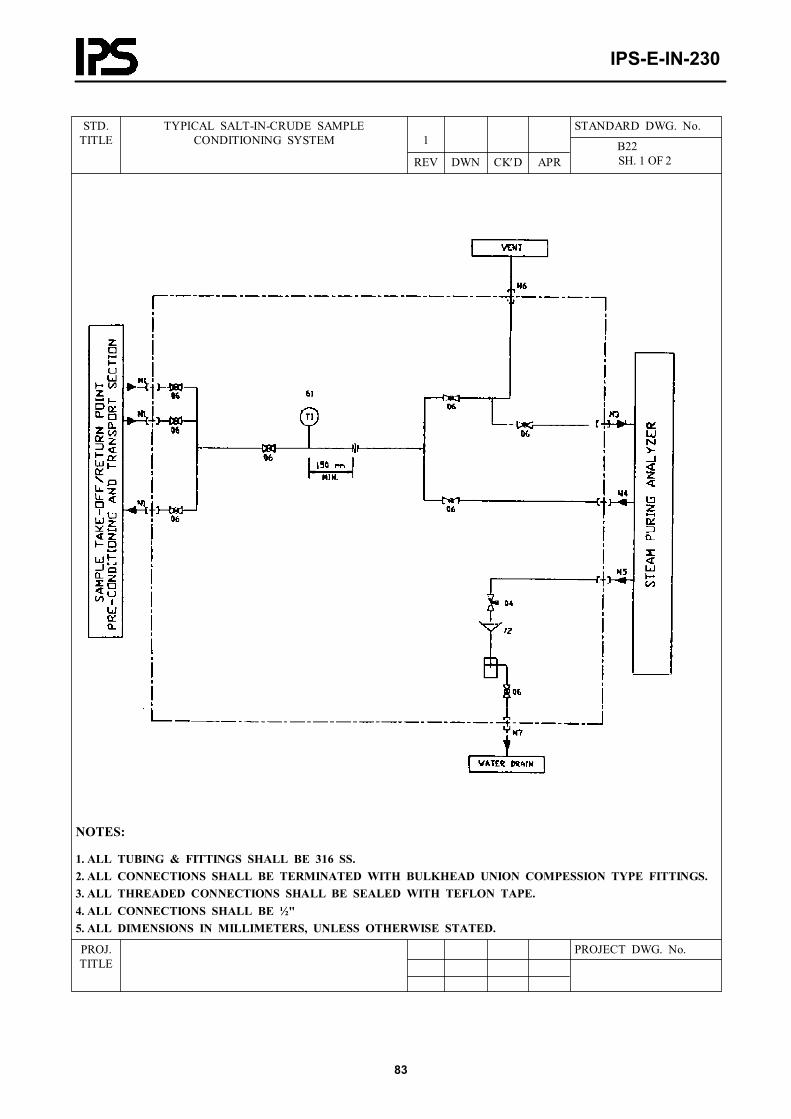
IPS-E-IN-230
83
STANDARD DWG. No.1
STD.TITLE
TYPICAL SALT-IN-CRUDE SAMPLE CONDITIONING SYSTEM
REV DWN CK′D APR B22
SH. 1 OF 2
NOTES:
1. ALL TUBING & FITTINGS SHALL BE 316 SS.2. ALL CONNECTIONS SHALL BE TERMINATED WITH BULKHEAD UNION COMPESSION TYPE FITTINGS.3. ALL THREADED CONNECTIONS SHALL BE SEALED WITH TEFLON TAPE.4. ALL CONNECTIONS SHALL BE ½"5. ALL DIMENSIONS IN MILLIMETERS, UNLESS OTHERWISE STATED.
PROJECT DWG. No.PROJ.TITLE

IPS-E-IN-230
84
STANDARD DWG. No.1
STD.TITLE
TYPICAL STEAM PURITY SAMPLE CONDITIONING SYSTEM
REV DWN CK′D APR B23
SH. 1 OF 2
NOTES:
1. ALL CONNECTIONS SHALL BE ¼" BULKHEAD UNION COMPESSION FITTINGS EXCEPT N9.2. N5 AND N8 ARE COOLING MEDIUM FROM AND TO REFRIGIRATOR
PROJECT DWG. No.PROJ.TITLE
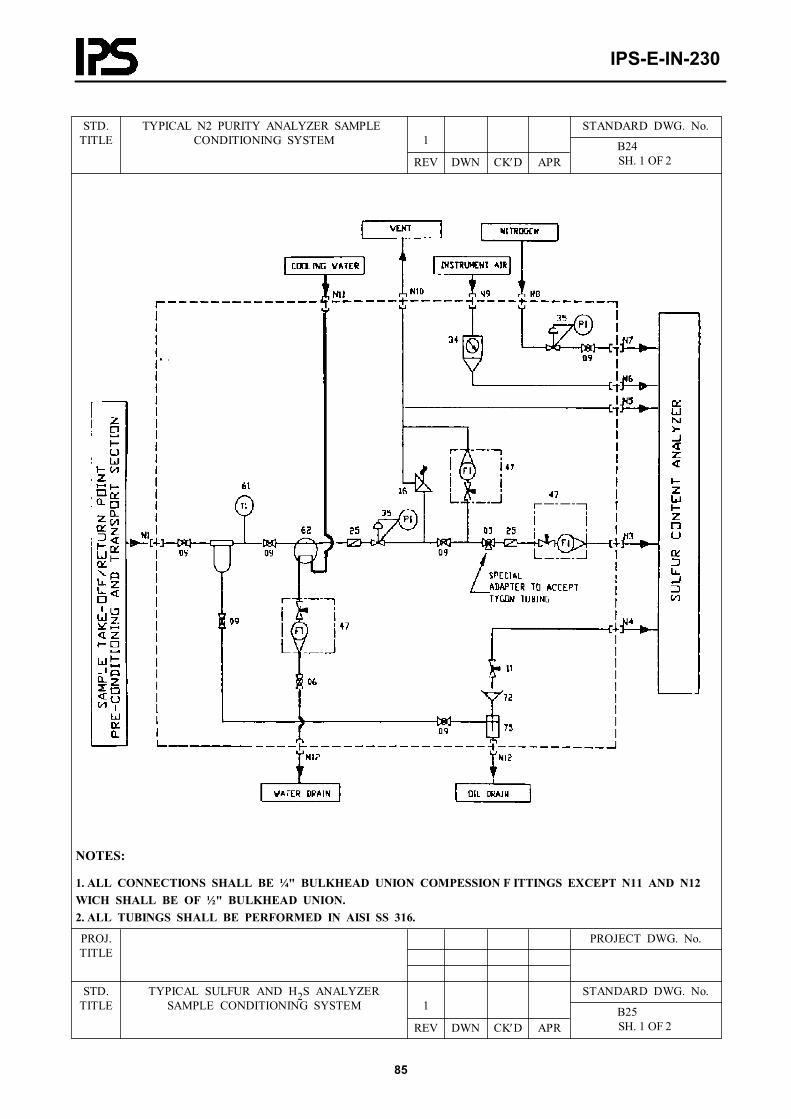
IPS-E-IN-230
85
STANDARD DWG. No.1
STD.TITLE
TYPICAL N2 PURITY ANALYZER SAMPLE CONDITIONING SYSTEM
REV DWN CK′D APR B24
SH. 1 OF 2
NOTES:
1. ALL CONNECTIONS SHALL BE ¼" BULKHEAD UNION COMPESSION F ITTINGS EXCEPT N11 AND N12 WICH SHALL BE OF ½" BULKHEAD UNION.2. ALL TUBINGS SHALL BE PERFORMED IN AISI SS 316.
PROJECT DWG. No.PROJ.TITLE
STANDARD DWG. No.1
STD.TITLE
TYPICAL SULFUR AND H2S ANALYZER SAMPLE CONDITIONING SYSTEM
REV DWN CK′D APR B25
SH. 1 OF 2

IPS-E-IN-230
86
APPENDIX CCOMPONENTS OF THE SAMPLE CONDITIONING SYSTEM
The Item numbers refer to the drawings of Appendix B.
ITEM DESCRIPTION SIZE010203040506070809111213141516172223242526272930313234353638394647484952536162717273747576818689
Bleed orificeThree-way valveThree-way valveNeedle valveT-FilterBall valveIsolate/vent valveGlobe valveBall valveNeedle valveCheck valveCheck valvePneumatic actuatorBall valve 3-wayRelief valveRelief valveStrainerBy-pass filterBy-pass filterRemovable filterCoalescerFilter/coalescerIn-line filterStrainerPressure regulatorBack-pressure regulatorFilter/regulatorPressure regulatorBack-pressure regulatorPressure gagePressure gageFlow meterFlow meter (with needle valve)Flow meter (with needle valve)Flow meterFlow controllerExcess flow valveTemperature gageCooler or heaterSample valve (change over)FunnelCalibration vesselCalibration vessel with diaphragm sealSyphonSight glassSample pumpGas drierBubbler/manostat
½" flanged ½" NPT(F) ¼" NPT(F) ½" NPT(F) ½" connections½" NPT(F) ½" NPT(F) ½" NPT(F) ¼" NPT(F) ¼" NPT(F) ½" NPT(F) ¼" NPT(F)
¼" NPT(F) ½" NPT(F) ¼" NPT(F) ½" NPT½" NPT¼" NPT
¼" NPT¼" NPT¼" NPT
½" NPT½" NPT¼" NPT¼" NPT¼" NPT½" NPT¼" NPT½" NPT½" NPT¼" NPT¼" NPT¼" NPT¼" NPT¼" NPT
½" NPT
½" NPT½" NPT
¼" NPT