engineering specification river ... - fortress.wa.gov bof-009/drawings... · river protection...
TRANSCRIPT

Issued byRPP-WTP PDC
• RIVER PROTECTION PROJECT - WASTE TREATMENT PLANT
ENGINEERING SPECIFICATION
FOR
DFLA W EMF Evaporator Feed Pre-Filter
Content applicable to A LARA?
ADR No. 24590-BOF-ADR-MS-16-0002
Specification changes retroactive?
~ Yes D No
Re,· 0
D \'es ~ No
Quality Level
CM D NIA (alpha re,•ision or revision 0)
DOE Contract No. Retroadive applicability:
NOTE: Contents of this document are Dangerous Waste Permit affecting.
0 7/30/16 llau Pau Su~jit Pabby
Originator h,11,:.q, Checked
3/t"lr?"' By Er,ca Pobri'!relny • ,p:,be,1!!2 8f ~ 5rlln f"""htn1
O,gNAl'llt 8Ktict1Na t.onel Ire. OrgH-htt#l "-hOl'lelll'IC
Plac..d u,wDl 2'017 Ptaud N.a Ol Xl17
I Erica Pobc:rczny Jung Shin
Rt:V DATE B\' cm:n,.
SPECIFICATION No. 24590-BOF-3PS-MLF0-T0002
NIA
v NIA
Al IHOIH.lA 1101\
DE-AC27-01 RV 14136
Youssef MohammadZadeh
Julian Lcam
Youssef Mohammatl/adch
/fl!\ ~~/1•/ll
Julian Lcam s//>/z.c,,7
I~: .. ~,.,;, "k' .r, l{s rl"( - -
APPROVER•
Rev I
•The designated procedure subject matter expert (SME) for 24590-WTP-3OP-G04B-00049. Engineering Spec(/icutions. will concur with the retroactive detem,ination and retroactive applicability details for all Specification Change Notices. Designated procedure SME ('oncun-ence is documented by the initials of the SME in or by the Approval box. See CCN 26377 l for details.
24590-G04B-F00009 Rev 20 (Revised 4/12/2017)
Pagei Rel: 24590-WT1'·31W-G04B-00049

24590-BOF-3PS-MLF0-T0002, Rev 1 DFLAW EMF Evaporator Feed Pre-Filter
Page ii 24590-G04B-F00009 Rev 20 (Revised 4/12/2017) Ref: 24590-WTP-3DP-G04B-00049
Revision History
Q Specification Revision Only
Margin Reduced? CM Only
Revision Reason for Revision YES NO N/A
0 Issued for Quote N/A N/A N/A
1 Issued for Purchase. Revised to conform to Seller's offering. Removed requirements for structural support carbon steel and coating requirements, including Exhibit 8 as lugs are used instead. Removed Exhibit 7 as it is not applicable. Exhibit 6 is replaced by new revision 4 of specification 24590-WTP-3PS-MVB2-T0002. Updated Restricted Materials List document number to 24590-WTP-LIST-ESH-16-0001. Incorporated specification change notice 24590-BOF-3PN-MLF0-00001. Incorporated EIE 24590-WTP-EIE-MS-16-0036. Adjusted sections 3.3.4.1, 10.1.4, and 10.2.1 for clarity.
• • ~
• • • • • •

24590-BOF-3PS-MLF0-T0002, Rev 1
DFLAW EMF Evaporator Feed Pre-Filter
Page iii
24590-G04B-F00019 Rev 4 (2/12/2008) Ref: 24590-WTP-3DP-G04B-00049
Notice
Please note that source, special nuclear, and byproduct materials, as defined in the Atomic Energy Act of 1954 (AEA), are regulated at the US Department of Energy (DOE) facilities exclusively by DOE acting pursuant to its AEA authority. DOE asserts, that pursuant to the AEA, it has sole and exclusive responsibility and authority to regulate source, special nuclear, and byproduct materials at DOE-owned nuclear facilities. Information contained herein on radionuclides is provided for process description purposes only.
24590-BOF-3PS-MLF0-T0002, Rev 1
DFLAW EMF Evaporator Feed Pre-Filter
Page iv
24590-G04B-F00019 Rev 4 (2/12/2008) Ref: 24590-WTP-3DP-G04B-00049
Contents
1 Scope .......................................................................................................................................1
1.1 Project Description and Location ......................................................................................................... 1
1.2 Equipment, Material, and Services Required ...................................................................................... 1
1.3 Work by Others ...................................................................................................................................... 2
1.4 Acronyms and System Designators ....................................................................................................... 2
1.5 Safety/Quality Classifications ................................................................................................................ 2
2 Applicable Documents ...........................................................................................................3
2.1 General .................................................................................................................................................... 3
2.2 Codes and Standards ............................................................................................................................. 3
2.3 Reference Documents/Drawings ........................................................................................................... 3
3 Design Requirements .............................................................................................................4
3.1 General .................................................................................................................................................... 4
3.2 Basic Function ........................................................................................................................................ 4
3.3 Performance ........................................................................................................................................... 5
3.4 Environmental Conditions .................................................................................................................... 6
3.5 Accessibility and Maintenance .............................................................................................................. 6
3.6 Loadings .................................................................................................................................................. 6
4 Materials .................................................................................................................................7
4.1 General .................................................................................................................................................... 7
4.2 Materials and Equipment ...................................................................................................................... 7
4.3 Construction ........................................................................................................................................... 7
4.4 Prohibited Materials .............................................................................................................................. 7
5 Fabrication .............................................................................................................................7
5.1 General .................................................................................................................................................... 7
6 Tests and Inspections ............................................................................................................8
6.1 General .................................................................................................................................................... 8
6.2 Shop Tests ............................................................................................................................................... 8
6.3 Non-Destructive Examination (NDE) ................................................................................................... 8
6.4 Inspection and Test Status ..................................................................................................................... 8
7 Preparation for Shipment .....................................................................................................9
7.1 General Requirements ........................................................................................................................... 9
7.2 Cleanliness .............................................................................................................................................. 9
7.3 Tagging and Marking ............................................................................................................................ 9

24590-BOF-3PS-MLF0-T0002, Rev 1
DFLAW EMF Evaporator Feed Pre-Filter
Page v
24590-G04B-F00019 Rev 4 (2/12/2008) Ref: 24590-WTP-3DP-G04B-00049
8 Quality Assurance ...............................................................................................................10
9 Configuration Management ...............................................................................................10
10 Documentation and Submittals ..........................................................................................10
10.1 General .................................................................................................................................................. 10
10.2 Submittals ............................................................................................................................................. 10 Attachment 1 - Evaporator Feed Pre-Filter Conceptual Flow Diagram…………...………... A-1
Exhibits EXHIBIT 1 | Positive Material Identification (PMI) for Shop-Fabrication …………………………… 1-1 EXHIBIT 2 | Structural Design Loads for Seismic Category III&IV Equipment and Tanks ...……… 2-1 EXHIBIT 3 | Pressure Vessel Design and Fabrication ………………………………………………….. 3-1 EXHIBIT 4 | Seismic Qualification Criteria for Pressure Vessels ……………………………………... 4-1 EXHIBIT 5 | Pressure Vessel Fatigue Analysis …………….……………………………………............. 5-1 EXHIBIT 6 | Deleted EXHIBIT 7 | Deleted EXHIBIT 8 | Deleted

24590-BOF-3PS-MLF0-T0002, Rev 1
DFLAW EMF Evaporator Feed Pre-Filter
Page 1
24590-G04B-F00019 Rev 4 (2/12/2008) Ref: 24590-WTP-3DP-G04B-00049
1 Scope
1.1 Project Description and Location
The Office of River Protection (ORP) and its contractors manage 177 underground radioactive waste storage tanks at the Hanford Site in Washington. These tanks contain approximately 56 million US gallons of radioactive waste. Bechtel National, Inc. (BNI) has entered into contract with the US Department of Energy to design, construct, and commission the Hanford Tank Waste Treatment and Immobilization Plant (WTP) to process and vitrify this waste into a stable form that is suitable for permanent storage or disposal. The WTP will be constructed in the 200 East Area of the Hanford Site, near Richland, Washington. The main facilities within the WTP complex will be the Pretreatment facility (PTF), Low-Activity Waste facility (LAW), High-Level Waste facility (HLW), Analytical Laboratory (Lab), Balance of Facilities (BOF) and the Effluent Management Facility (EMF).
1.2 Equipment, Material, and Services Required
This specification describes the minimum technical requirements for the design, fabrication, and testing of a Commercial Grade (CM) Evaporator Feed Pre-filter for use in the EMF. This Pre-filter is to be a candle type filter.
In case of conflict between any requirement specified herein and the requirements of any other referenced document, the SELLER shall call attention to the conflict and request an interpretation by the BUYER. All deviations considered for incorporation in the work must be submitted to the BUYER on completed SDDR form for BUYER’s approval.
The scope of work for the SELLER includes, but is not limited to, the following:
1.2.1 Furnish a candle filter assembly in accordance with this specification. The SELLER shall provide the items listed below (per associated candle filter MDS) that meets the requirements of this specification, applicable industry codes, and their design.
a) Filter vessel with all internals b) Full description of operational modes and the logic associated with each mode and the
transition between modes. c) Full description and listing of instrumentation and controls necessary for operation of the
filter during all operational modes.
1.2.2 Provide the documents, as submittals per the G-321-E, Engineering Document Requirements, and G-321-V, Quality Verification Document Requirements forms attached to the Material Requisition (MR).
1.2.3 The SELLER may subcontract portions of the work, including any portion of the design, fabrication, manufacturing, or inspection, provided it meets the conditions of this specification.

24590-BOF-3PS-MLF0-T0002, Rev 1
DFLAW EMF Evaporator Feed Pre-Filter
Page 2
24590-G04B-F00019 Rev 4 (2/12/2008) Ref: 24590-WTP-3DP-G04B-00049
1.3 Work by Others
The following items and services will be supplied by the BUYER and are not included in the SELLER’s scope of work:
1.3.1 Installation at BUYER’s facility including installation labor and interconnecting piping.
1.3.2 Instrumentation and controls, including pressure transmitter, level transmitter, actuated nozzle mount valves and installation.
1.3.3 Filter vessel pressure relief valves (to be installed in connecting piping).
1.3.4 Deleted
1.3.5 Utility (i.e. air, steam, service water, demineralized water and cooling water) supply systems.
1.3.6 Foundation for anchorage.
1.3.7 Thermal insulation
1.3.8 Material Conveyance
1.3.9 Structural support, including platforms.
1.3.10 Connecting piping.
1.4 Acronyms and System Designators
1.4.1 Acronyms and Definitions
ASME American Society of Mechanical Engineers BUYER Bechtel National, Incorporated CM Commercial Grade EMF Effluent Management Facility MDS Mechanical Data Sheet MTR Material Test Report MR Material Requisition NDE Non-Destructive Examination NTE Not-to-Exceed P&ID Piping and Instrument Diagram PMI Positive Material Identification QAP Quality Assurance Program SC Seismic Category SDDR Supplier Deviation Disposition Request SELLER The party to whom the contract for work described herein has been awarded WTP Hanford Tank Waste Treatment and Immobilization Plant
1.5 Safety/Quality Classifications
1.5.1 The components specified in this specification do not perform a safety function and are therefore identified with a “Commercial Grade (CM)” classification.

24590-BOF-3PS-MLF0-T0002, Rev 1
DFLAW EMF Evaporator Feed Pre-Filter
Page 3
24590-G04B-F00019 Rev 4 (2/12/2008) Ref: 24590-WTP-3DP-G04B-00049
1.5.2 The candle filter vessel and all internals shall be designed as Seismic Category IV (SC-IV).
2 Applicable Documents
2.1 General
2.1.1 When specific chapters, sections, parts, or paragraphs are listed following a code, industry standard, or reference document, only those chapters, sections, parts, or paragraphs of the document are applicable and shall be applied.
2.1.2 For the codes and standards listed in Section 2.2, the specific edition year identified shall be followed. For the codes and standards that are incorporated by reference (daughter codes and standards), the referenced daughter edition or current edition shall be followed. If an edition year is not identified, the latest issue, including addenda, at the time of award shall apply.
2.1.3 The edition year listed in Section 2.2 shall apply to, and govern in case of conflict with subsequent references to the codes and standards within the referenced documents in section 2.3 and exhibits. SELLER shall notify the Buyer when conflicts are identified for determination of applicable code/standard to be followed.
2.1.4 In case of conflict between this specification and referenced codes and standards, the requirements for all must be met with the most stringent governing. In the evet the Seller is unable to meet code or standard, SELLER shall notify BUYER via the SDDR process.
2.2 Codes and Standards
2.2.1 ASME B46.1, Surface Texture (Surface Roughness, Waviness and Lay)
2.2.2 ASME Boiler and Pressure Vessel Code, Section II: Materials
2.2.3 ASME Boiler and Pressure Vessel Code, Section VIII, Div. 1: Rules for Construction of Pressure Vessels
2.2.4 ASME Y14.100, Engineering Drawing Practices
2.2.5 ASTM B688, Standard Specification for Chromium-Nickel-Molybdenum-Iron (UNS N08366 and UNS N08367) Plate, Sheet, and Strip
2.3 Reference Documents/Drawings
2.3.1 Reference Documents
2.3.1.1 24590-WTP-3PS-G000-T0003, Engineering Specification for Packaging, Handling, and Storage Requirements
2.3.1.2 24590-WTP-3PS-G000-T0014, Engineering Specification for Supplier Design Analyses
2.3.1.3 24590-WTP-LIST-ESH-16-0001, Restricted Materials List
2.3.1.4 24590-WTP-3PS-MVB2-T0001, Engineering Specification for Welding of Pressure Vessels, Heat Exchangers and Boilers*
*Replace any reference to 24590-WTP-3PS-MV00-T0001 in this document with Exhibit 3 of this specification.

24590-BOF-3PS-MLF0-T0002, Rev 1
DFLAW EMF Evaporator Feed Pre-Filter
Page 4
24590-G04B-F00019 Rev 4 (2/12/2008) Ref: 24590-WTP-3DP-G04B-00049
2.3.2 Reference Drawings
2.3.2.1 24590-WTP-MV-M59T-00001, Pressure Vessel Tolerances Standard Details
2.3.2.2 24590-WTP-MV-M59T-00009, Lifting Lugs Standard Details
2.3.2.3 24590-WTP-MV-M59T-00010, Tailing Lug Standard Details
2.3.2.4 24590-WTP-MV-M59T-00012, Grounding Lug Standard Details
2.3.2.5 24590-WTP-MV-M59T-00016001, Vessel Connections Standard Details Sheet 1 of 3
2.3.2.6 24590-WTP-MV-M59T-00016002, Vessel Connections Standard Details Sheet 2 of 3
2.3.2.7 24590-WTP-MV-M59T-00016003, Vessel Connections Standard Details Sheet 3 of 3
2.3.2.8 24590-WTP-MV-M59T-00018, Vessel Name Plate Standard Details
2.3.2.9 24590-WTP-MV-M59T-00026, Anchor Bolt Chair Details for Vertical Vessels
2.3.2.10 24590-WTP-PW-P30T-00001, WTP End Prep Detail for Field Butt Welds
3 Design Requirements 3.1 General
3.1.1 The SELLER shall comply with all applicable Sections of Exhibit 3, Pressure Vessel Design and Fabrication.
3.1.2 The candle filter and associated internals covered by this specification shall be designed for a minimum design life of 40 years, unless otherwise noted, inclusive of maintenance. Design life of equipment shall consider the effects of chemical, radiological, and thermal exposure.
3.1.3 SELLER shall provide an analysis of design life for the candle filter assembly, including its internal components, and justify all assumptions and references. All engineering analyses and calculations provided as supplier submittals shall be in accordance with 24590-WTP-3PS-G000-T0014, Engineering Specification for Supplier Design Analyses. The analysis shall be included with the calculation submittals in Section 10.2.9.4
3.2 Basic Function
3.2.1 Unless otherwise specified, the candle filter equipment shall be designed and fabricated in accordance with the requirements identified in the Mechanical Data Sheet (MDS), and any additional requirements of this specification. Any difference between SELLER’s final design and BUYER’s data specified in the MDS shall be identified to the BUYER for resolution.
3.2.2 The filter media shall be re-useable spring loaded disk type, sintered metal, ceramic, or other permanent filter element material. The filter media material shall be capable of being cleaned as necessary by chemical cleaning solutions such as 0.5 M nitric acid either while in place or when removed from the filter housing.

24590-BOF-3PS-MLF0-T0002, Rev 1
DFLAW EMF Evaporator Feed Pre-Filter
Page 5
24590-G04B-F00019 Rev 4 (2/12/2008) Ref: 24590-WTP-3DP-G04B-00049
3.2.3 The candle filter nozzles shall be configured generally as depicted in the sketch provided in Attachment 1 (page A-1). This includes connections as shown in the nozzle schedule on MDS.
3.2.4 As shown in Attachment 1, normal flow to the filter will come from three sources that enter the filter through three different nozzles. Flow to the filter will only come from one of the three sources at a time during filtration. The candle filter shall be constructed to ASME Section VIII, Div. 1 requirements and shall have an ASME code stamp and National Board Registration.
3.2.5 Three (3) evenly spaced inlet connections (1”, 2”, and 3”) and one (1) outlet connection (3”) located on the bottom head of the filter vessel are required. Nozzle length shall be minimized to the extent practical.
3.3 Performance
3.3.1 General
3.3.1.1 The performance characteristics of equipment shall be in accordance with the MDS.
3.3.2 Filter Vessel
3.3.2.1 A Fatigue evaluation and fatigue analysis, where required, shall be conducted in accordance with Exhibit 5, Pressure Vessel Fatigue Analysis.
3.3.2.2 SELLER shall provide a recommended list and number of spare parts for BUYER’s review.
3.3.2.3 The SELLER shall make provision for insulation as required.
3.3.3 Filter Operational Philosophy
3.3.3.1 SELLER shall provide a detailed description of the operational sequence for the candle filter. All valves, instrumentation, and other piping and instrumentation items that are required to perform operation of the filter shall be shown on a P&ID drawing supplied by the SELLER. The operational description shall include details of the pressure, flow, and any other operational parameters that will need to be monitored and/or controlled by the BUYER during the:
a Filtration mode, including valve line-up and sequence of actuation for filtration mode. Also, specify the minimum system pressure that must be maintained in the filter vessel to hold the filter cake on the candles during filtration mode.
b Filter cake discharge mode, including the pressure to which the filter vessel headspace will need to be pressured to in order to remove the filter cake on the candle filter elements.
c Reset for operation, including venting process for removing air trapped in filter vessel headspace during solids dislodging and discharge.
d Any operational considerations associated with chemical cleaning as specified in Section 3.2.2.

24590-BOF-3PS-MLF0-T0002, Rev 1
DFLAW EMF Evaporator Feed Pre-Filter
Page 6
24590-G04B-F00019 Rev 4 (2/12/2008) Ref: 24590-WTP-3DP-G04B-00049
3.3.4 Filter Cake Discharge
3.3.4.1 The required method for discharge of the filter cake at the end of the filtration cycle is a pressurized release of air from the backside to the filter medium (snap/blow).
3.3.4.2 Deleted
3.3.4.3 Deleted
3.3.4.4 Deleted
3.4 Environmental Conditions
3.4.1 The filter shall be designed, equipped, and furnished to be fully operational throughout the entire range between, and including the limits of, the minimum and maximum conditions specified on the MDS.
3.4.2 Equipment average contact dose rate are as specified on the MDS.
3.5 Accessibility and Maintenance
3.5.1 The design of the filter vessel shall support the ability to open the filter vessel and lift out the candle filter assembly and move it horizontally to a location adjacent to the filter vessel for maintenance and/or cleaning.
3.6 Loadings
3.6.1 Loads to be considered for the structural design of the filter vessel, including filter vessel supports, and associated internal /external components shall be in accordance with applicable codes, standards, and reference documents listed in Section 2 of this specification.
3.6.2 SELLER shall include the location of the anchorage in filter vessel outline drawings supplied to the BUYER. In addition to location, the SELLER shall provide the BUYER maximum anchorage loads for all load cases (including seismic per Section 3.6.4). Vessel nozzle loading analysis shall be done in accordance with ASME Section VIII and Exhibit 3, Pressure Vessels Design and Fabrication and reported as required by submittals listed in the MR.
3.6.3 SELLER shall complete a seismic analysis of the filter vessel assembly and components.
3.6.4 Seismic load capability requirements of the vessel components shall be calculated in accordance with Exhibit 2, Structural Design Loads for Seismic Category IV Equipment and Tanks.
3.6.5 Vessel seismic analysis shall be performed per the requirements of Exhibits 3, Pressure Vessel Design and Fabrication, Section 3.2 and Exhibit 4, Seismic Qualification Criteria for Pressure Vessels.
3.6.6 SELLER shall comply with nozzle loading requirements in Exhibit 3, Pressure Vessel Design and Fabrication, Section 3.7.

24590-BOF-3PS-MLF0-T0002, Rev 1
DFLAW EMF Evaporator Feed Pre-Filter
Page 7
24590-G04B-F00019 Rev 4 (2/12/2008) Ref: 24590-WTP-3DP-G04B-00049
3.6.7 SELLER shall provide four (4) support lugs on the bottom section of the vessel (lugs shall be located as close as permissible to the flange joint between the bottom and top sections of the filter). In addition, four (4) lifting lugs shall be provided on the top head of the filter.
4 Materials 4.1 General
The SELLER shall comply with all requirements of Section 4 of Exhibit 3, Pressure Vessel Design and Fabrication.
4.2 Materials and Equipment
4.2.1 Provide equipment and components with the materials of construction as specified per this specification and on the listed data sheet in Part 2 of the MR. Where specific criteria are not provided, material selection shall be determined by the SELLER and have properties and composition suitable for the specific service conditions and consistent with this specification and its addenda.
4.2.2 Corrosion and erosion allowance is specified on the MDS and shall be applied to each surface exposed to process liquid. The SELLER shall not substitute materials without written approval, via the SDDR process from the BUYER.
4.2.3 SELLER shall comply with the requirements in Exhibit 1, Positive Material Identification (PMI).
4.2.4 Deleted
4.3 Construction
4.3.1 For vessels, classification of fabrication materials for bolts and nuts shall be in accordance with ASME Boiler and Pressure Vessel Code, Section II.
4.3.2 Deleted
4.4 Prohibited Materials
4.4.1 The materials listed in 24590-WTP-LIST-ESH-16-0001, Restricted Materials List shall not be used on any supplied equipment and shall not be brought onto WTP site.
4.4.2 Bronze, copper, lead, zinc, tin, antimony, cadmium, their alloys or materials containing such metals as their basic constituents, or molybdenum and halogens, shall not be used in direct contact with stainless steel.
5 Fabrication 5.1 General
5.1.1 The SELLER shall comply with requirements of Sections 5 and 6 of Exhibit 3, Pressure Vessel Design and Fabrication.

24590-BOF-3PS-MLF0-T0002, Rev 1
DFLAW EMF Evaporator Feed Pre-Filter
Page 8
24590-G04B-F00019 Rev 4 (2/12/2008) Ref: 24590-WTP-3DP-G04B-00049
5.1.2 The SELLER shall fabricate the filter vessel and associated components, in accordance with the BUYER standard details listed under section 2.3.2 of this specification.
5.1.3 Design of filter vessel supports shall be in accordance with Exhibit 3, Pressure Vessel Design and Fabrication, Section 3.10 and 24590-WTP-3PS-MVB2-T0001, Engineering Specification for Welding of Pressure Vessels, Heat Exchanger and Boilers.
5.1.4 All fabrication shall be performed by personnel qualified in accordance with this specification and applicable documents referenced in Section 2 and exhibits of this specification.
5.1.5 For the equipment supplied per this specification, the SELLER shall ensure that all sharp edges are broken/smoothed and all burrs removed. Machined metal surfaces subjected to human touch through maintenance or operational reason shall be constructed to have no sharp edges unless it serves the function of the equipment.
5.1.6 Machined exposed metal surfaces shall have a surface finish of 125 microinches per ASME B46.1, Surface Texture (Surface Roughness, Waviness and Lay).
5.1.7 Deleted
6 Tests and Inspections 6.1 General
6.1.1 The SELLER shall comply with all requirements of Section 7 of Exhibit 3, Pressure Vessel Design and Fabrication.
6.1.2 The SELLER shall submit original set of radiographic film with associated technique and reader sheets in accordance with Section 7.2 of Exhibit 3, Pressure Vessel Design and Fabrication. In addition, the SELLER shall submit original set of vessel assembly seam weld radiographic film. Film shall be packaged to preclude moisture and handling damage.
6.2 Shop Tests
6.2.1 All test results shall be documented, certified, and submitted to the BUYER for review, in accordance with G-321-V, Quality Verification Document Requirements forms attached to the MR.
6.2.2 SELLER shall furnish blind flanges or other acceptable closures for the nozzles, as required for hydrotesting. Closures shall be removed after testing, unless they are required for shipment.
6.3 Non-Destructive Examination (NDE)
6.3.1 The filter vessel shall meet the requirements for welding and non-destructive examination (NDE) from the following specifications:
a) Exhibit 3, Pressure Vessel Design and Fabrication, Sections 6 and 7.2.
6.4 Inspection and Test Status

24590-BOF-3PS-MLF0-T0002, Rev 1
DFLAW EMF Evaporator Feed Pre-Filter
Page 9
24590-G04B-F00019 Rev 4 (2/12/2008) Ref: 24590-WTP-3DP-G04B-00049
6.4.1 The SELLER shall maintain a system for identifying inspection and testing status of items and systems.
7 Preparation for Shipment 7.1 General Requirements
7.1.1 The SELLER shall comply with all requirements of Section 8 of Exhibit 3, Pressure Vessel Design and Fabrication.
7.1.2 The filter vessel shall be packaged, prepared for shipment, handled, and stored in accordance with 24590-WTP-3PS-G000-T0003 (Ref. 2.3.1.1), Engineering Specification for Packaging, Handling, and Storage Requirements; excluding any NQA-1 requirements.
7.1.3 All equipment shall be thoroughly cleaned of all debris, trash, weld splatter, loose mill scale, tools and foreign matter and dried in preparation for shipment.
7.2 Cleanliness
7.2.1 Seller’s cleaning procedures shall be submitted to the Buyer for review.
7.2.2 Prior to surface preparation, visually examine welds, all internal and surfaces of the filter housing. Remove all dirt, oil and grease, loose mill scale, weld spatter and other foreign matter.
7.3 Tagging and Marking
7.3.1 The equipment shall be marked and labeled in accordance with 24590-WTP-3PS-G000-T0003, Engineering Specification for Packaging, Handling, and Storage Requirements, Section 6. Component numbers shall be per the MDS. In case of conflict, SELLER shall submit a report identifying any deviations and/or conflicts on an SDDR form, attached to the MR.
7.3.2 Slinging points and orientation for storage shall be clearly marked.
7.3.3 A stainless steel nameplate shall be rigidly attached to the vessels in a prominent position for ease of visibility, unless a location is indicated on the drawings. The nameplate physical location shall be visible after insulation is installed. Nameplates shall include the following, in addition to all markings mandated by the vessel design standard at a minimum:
a) Manufacturer’s name b) Shop location c) Date of manufacture d) Serial number e) Equipment name and tag number f) Weight of assembly g) Purchase order number h) Design pressure i) Hydro test pressure

24590-BOF-3PS-MLF0-T0002, Rev 1
DFLAW EMF Evaporator Feed Pre-Filter
Page 10
24590-G04B-F00019 Rev 4 (2/12/2008) Ref: 24590-WTP-3DP-G04B-00049
8 Quality Assurance The Seller’s manufacturing Quality Assurance Program (QAP) applicable to production of standard product offerings is acceptable to meet the requirements of this procurement.
9 Configuration Management Equipment and/or components covered by this specification are identified with Plant Item Numbers shown in the listed MDS in Part 2 of the MR. Each item shall be identified in accordance with Section 7.3 of this specification. Configuration Management is maintained by conformance to approved drawings and procedures.
10 Documentation and Submittals 10.1 General
10.1.1 The SELLER shall comply with all requirements of Section 9 of Exhibit 3, Pressure Vessel Design and Fabrication.
10.1.2 SELLER shall submit to BUYER all detailed designs, drawings, documentation, procedures, instructions, calculations, analyses, manufacturer documentation, manufacturer data, inspection reports, test reports, certificates, and manuals required per this specification, the applicable codes, standards, and reference documents in Section 2 of this specification, and the MR.
10.1.3 Documentation shall be submitted to BUYER as summarized on the G-321-E, Engineering Document Requirements, and G-321-V, Quality Verification Document Requirements forms attached to the MR.
10.1.4 SELLER shall prepare and submit a completed Form 15EX as required by Attachment DD “Document and Data Submittal Requirements” of the associated MR, which shall include the planned schedule for submitting the documents required by this specification and the MR Form G-321-E, Document Category 1.0.
10.1.5 Deleted
10.1.6 All drawings shall be produced per the drawing practices set forth in ASME Y14.100, Engineering Drawing Practices.
10.2 Submittals
10.2.1 Schedule and Drawing Index
SELLER shall submit an engineering and fabrication schedule detailing the chronological sequence of events per G-321-E, Document Category 5.0. The schedule shall include Supplier Quality witness/hold points, as applicable. The schedule does not suffice for formal notification of witness/hold points for which a separate notification is still required in accordance with the witness/hold point requirements.

24590-BOF-3PS-MLF0-T0002, Rev 1
DFLAW EMF Evaporator Feed Pre-Filter
Page 11
24590-G04B-F00019 Rev 4 (2/12/2008) Ref: 24590-WTP-3DP-G04B-00049
10.2.2 Data Sheets
10.2.2.1 Mechanical Data Sheets
SELLER shall provide completed Mechanical Data Sheets as listed in Part 2 of the MR.
10.2.3 Drawings
10.2.3.1 Outline Drawings
SELLER shall provide drawings with outline dimensions, services, foundations, and mounting details. Drawings shall show external envelope, including lugs, and centerline(s), fluid, other service connections, isometrics, and details related to filter vessel supports. Outline drawings are to include the filter vessel as well as internal components.
In addition, shop detail drawings shall meet the requirements from the following:
A) Exhibit 3, Pressure Vessel Design and Fabrication, Section 9.6.
B) Section 3.6.2 of this specification
10.2.3.2 Shop Detail Drawings and Bill of Materials (BOM)
SELLER shall provide shop detail drawings with sufficient detail to facilitate fabrication, manufacture, or installation. This includes a complete Bill of Materials (BOM), cross-section details, and structural details.
In addition, shop detail drawings shall meet the requirements from the following:
Exhibit 3, Pressure Vessel Design and Fabrication, Section 9.6.
10.2.3.3 Vessel Nozzle Locations and Connection Details
SELLER shall provide filter vessel nozzle locations and connection details. Nozzle locations shall be in a configuration that conforms to the BUYER-supplied model picture in Attachment 1.
10.2.4 Lists
10.2.4.1 Material List
SELLER shall provide a material list with specific model number, manufacturer, and catalog cut sheets for all equipment.
10.2.4.2 Recommended Spare Parts List
SELLER shall provide a list of recommended spare parts and supplies for maintainable vessel components required for maintenance and repair to ensure continued service or operation without unreasonable delays, including the cost of each item. The SELLER shall also provide a list of startup and commissioning spares, including all components or equipment that may be needed during startup and commissioning.

24590-BOF-3PS-MLF0-T0002, Rev 1
DFLAW EMF Evaporator Feed Pre-Filter
Page 12
24590-G04B-F00019 Rev 4 (2/12/2008) Ref: 24590-WTP-3DP-G04B-00049
10.2.5 Product Data
10.2.5.1 Inspections and Test Plans
SELLER shall provide a detailed description of their work inspections and tests planned during the receipt of materials, manufacturing, testing, and conformance verification activities. SELLER shall include identification of witness and hold points. In addition, SELLER shall provide inspection and test plans in accordance with Exhibit 3, Pressure Vessel Design and Fabrication, Section 9.7.
10.2.5.2 Structural Support Requirements
SELLER shall provide structural support data and drawings with recommended support locations for vessels (i.e., load points, weight distribution, and maximum weight, geometry of equipment, and location of center gravity).
10.2.5.3 Transportation and Shipping Documentation
SELLER shall provide shipping information in accordance with 24590-WTP-3PS-G000-T0003, Engineering Specification for Packaging, Handling, and Storage Requirements, Section 11.2 and Sections 7.1.1 and 7.1.3 of this specification.
10.2.6 Manuals
10.2.6.1 Installation Instruction Manual
SELLER shall submit an Installation Instruction Manual with drawings and procedures required for safe assembly and installation of material, including any explanations for special tools in accordance with 24590-WTP-3PS-G000-T0003, Engineering Specification for Packaging, Handling, and Storage Requirements, Section 11.1.1.
10.2.6.2 Operation and Maintenance Manuals and Instructions
SELLER shall submit manuals with detailed instructions relating to operation of the candle filter system in all modes as indicated in Section 3.3.3.1.
SELLER shall submit maintenance manuals with detailed written instructions to disassemble, reassemble, and maintain components. Manuals shall include specific instructions, procedures, and illustrations for preventative and corrective maintenance. Provide a list of special tools required for maintenance and repair of components.
Corrective maintenance manuals shall include the manufacturer’s procedures and instructions for correcting problems and making repairs. Provide a troubleshooting guide and diagnostic techniques, maintenance and repair procedures, removal and replacement instructions for components, identification of all parts of end items subject to replacement (including special hardware requirements), warranty information, and personnel training requirements for operating and maintaining equipment.

24590-BOF-3PS-MLF0-T0002, Rev 1
DFLAW EMF Evaporator Feed Pre-Filter
Page 13
24590-G04B-F00019 Rev 4 (2/12/2008) Ref: 24590-WTP-3DP-G04B-00049
10.2.6.3 Site Storage, Handling, and Maintenance Requirements Manual
SELLER shall submit a Site Storage, Handling, and Maintenance Requirements Manual with procedures and instructions for site storage, handling, and maintenance that will preserve equipment until it is put into operation in accordance with 24590-WTP-3PS-G000-T0003, Engineering Specification for Packaging, Handling, and Storage Requirements, Section 11.1.2.
10.2.7 Procedures
10.2.7.1 Welding and NDE Procedures and Qualifications
SELLER shall provide welding, weld inspection, NDE, and weld repair procedures and personnel qualifications in accordance with the following:
a) 24590-WTP-3PS-MVB2-T0001, Engineering Specification for Welding of Pressure Vessels, Heat Exchangers, and Boilers, Section 4.
b) Exhibit 3, Pressure Vessel Design and Fabrication, Sections 5.4 and 7.2.
10.2.7.2 Material Control Procedures
SELLER shall provide material control procedures including controlling issuance, handling, storage, and traceability of materials such as weld rod.
10.2.7.3 Deleted
10.2.7.4 Positive Material Identification (PMI) Procedures
SELLER shall submit procedures covering how PMI will be conducted and documented per Exhibit 1, Positive Material Identification (PMI), Section 3.2.
10.2.7.5 Inspection Procedure
SELLER shall provide inspection procedures for the purpose of determining that specified requirements (e.g. dimensions, properties, performance results, etc.) are met.
10.2.7.6 Heat Treatment Procedure
SELLER shall submit a procedure for heat treatment per Exhibit 3, Pressure Vessel Design and Fabrication.
10.2.7.7 Pressure Test Procedure
SELLER shall submit pressure testing procedures including hydro, air, leak, separation, or vacuum test procedures for performing hydrostatic or pneumatic structural integrity and leakage tests per Exhibit 3, Pressure Vessel Design and Fabrication, and Section 6.2 of this specification.
10.2.7.8 Hardness Testing Procedure
SELLER shall submit a procedure for hardness testing per Exhibit 3, Pressure Vessel Design and Fabrication, Section 7.1.4.

24590-BOF-3PS-MLF0-T0002, Rev 1
DFLAW EMF Evaporator Feed Pre-Filter
Page 14
24590-G04B-F00019 Rev 4 (2/12/2008) Ref: 24590-WTP-3DP-G04B-00049
10.2.7.9 Nozzle Loading
SELLER shall submit an analysis for nozzle loading in accordance with Exhibit 3, Pressure Vessel Design and Fabrication, Section 3.7.
10.2.8 Reports
10.2.8.1 Seismic Analysis
SELLER shall provide a seismic analysis as required in Section 3.6.3 of this specification. Analysis shall demonstrate suitability of materials, components, or systems in relation to the conditions imposed by the stated seismic criteria.
10.2.8.2 NDE Records
SELLER shall keep records pertaining to NDE, base materials, filler materials, fabrication, and inspection in accordance with Exhibit 3, Pressure Vessel Design and Fabrication, Section 6.1 and 9.4 and 24590-WTP-3PS-MVB2-T0001, Engineering Specification for Welding of Pressure Vessels, Heat Exchangers and Boilers, Section 12.
10.2.8.3 Test Reports for Vessels and Piping
SELLER shall supply quality records and test results for the following items in accordance with Exhibit 3, Pressure Vessel Design and Fabrication, Sections 6.4.2, 7.5, and 9.8. Test reports shall include, as applicable:
a) Heat treat reports. b) Ultrasonic examination and verification reports. c) Radiographic examination and verification reports. d) RT film and reader sheets. e) Liquid penetrant examination and verification reports. f) Pressure testing and verification reports. g) Inspection and verification reports. h) Mechanical test reports. i) Obstruction reports.
10.2.8.4 ASME Data Reports
SELLER shall provide ASME Boiler and Pressure Vessel Code Section VIII data reports in accordance with Exhibit 3, Pressure Vessel Design and Fabrication, Section 9.5.
10.2.8.5 Positive Material Identification (PMI) Reports
SELLER shall submit PMI testing reports, including a PMI map per Exhibit 1, Positive Material Identification (PMI), Section 6.
10.2.8.6 Material Test Reports
SELLER shall submit material test reports (MTR) and/or Certificates of Compliance (C of C) in accordance with the following:
a) Deleted
24590-BOF-3PS-MLF0-T0002, Rev 1
DFLAW EMF Evaporator Feed Pre-Filter
Page 15
24590-G04B-F00019 Rev 4 (2/12/2008) Ref: 24590-WTP-3DP-G04B-00049
b) 24590-WTP-3PS-MVB2-T0001, Engineering Specification for Welding of Pressure Vessels, Heat Exchanger and Boilers, Section 6.1.4.
c) Deleted
10.2.8.7 Ferrite Data
SELLER shall submit ferrite data on welding materials in accordance with the following:
a) 24590-WTP-3PS-MVB2-T0001, Engineering Specification for Welding of Pressure Vessels, Heat Exchanger and Boilers, Section 6.1.1.
10.2.8.8 Certificates and Inspection Reports
SELLER shall provide certificates and inspection reports.
10.2.8.9 Record of any Major Weld Repairs
SELLER shall submit a record for any major weld repairs if applicable per 24590-WTP-3PS-MVB2-T0001, Engineering Specification for Welding of Pressure Vessels, Heat Exchangers and Boilers, Section 4.1.5.
10.2.8.10 Weld Map
SELLER shall submit a weld map for each weld in accordance with 24590-WTP-3PS-MVB2-T0001, Engineering Specification for Welding of Pressure Vessels, Heat Exchangers, and Boilers, Section 11. Include NDE/PMI maps on the weld map drawings.
10.2.8.11 Analysis and Design Report
SELLER shall provide analysis and design reports, including analytical data (stress, fluid dynamics, etc.), which demonstrates that an item satisfies all specified requirements.
10.2.8.12 Material Verification Report
SELLER shall certify in writing that material of each component is verified.
10.2.8.13 Deleted
10.2.9 Calculations and Analysis
10.2.9.1 Design Calculations for Filter Vessel
SELLER shall submit design calculations, including code calculations, in accordance with Exhibit 3, Pressure Vessel Design and Fabrication, Section 9.2.
10.2.9.2 Fatigue Evaluation and Analysis
SELLER shall submit a fatigue evaluation and a fatigue analysis, where required, in accordance with Exhibit 5, Pressure Vessel Fatigue Analysis, Section 12, prior to commencement of fabrication.
10.2.9.3 Nozzle Loading Calculation

24590-BOF-3PS-MLF0-T0002, Rev 1
DFLAW EMF Evaporator Feed Pre-Filter
Page 16
24590-G04B-F00019 Rev 4 (2/12/2008) Ref: 24590-WTP-3DP-G04B-00049
SELLER shall submit nozzle loading calculations in accordance with the Exhibit 3, Pressure Vessel Design and Fabrication, Section 9.2.
10.2.9.4 Design Life Analysis
SELLER shall submit a design life analysis per Section 3.1.3 of this specification.

24590-BOF-3PS-MLF0-T0002, Rev 1
DFLAW EMF Evaporator Feed Pre-Filter
Page A-1
24590-G04B-F00019 Rev 4 (2/12/2008) Ref: 24590-WTP-3DP-G04B-00049
Attachment 1 – Evaporator Feed Pre‐Filter Conceptual Flow Diagram
Spare
N05
N09
N10
N06
N02Filtered Effluent
Solids Backflush
Filtered Effluent
Normal OperationNon-routine Operation
Various Feed Streams
Backflush Stream - PSA
N03
N08
Pressure TransmitterN01
LevelTransmitter
N04
c=>--------+ C> ·i
.________J
I I I
'----c=>
I I I ._________.J I ,__________/
I
c=)---------·- : ---------1 I= I L...____
24590-BOF-3PS-MLF0-T0002, Rev 1 DFLAW EMF Evaporator Feed Pre-Filter
Exhibit 1, Page 1-1
24590-G04B-F00019 Rev 4 (2/12/2008) Ref: 24590-WTP-3DP-G04B-00049
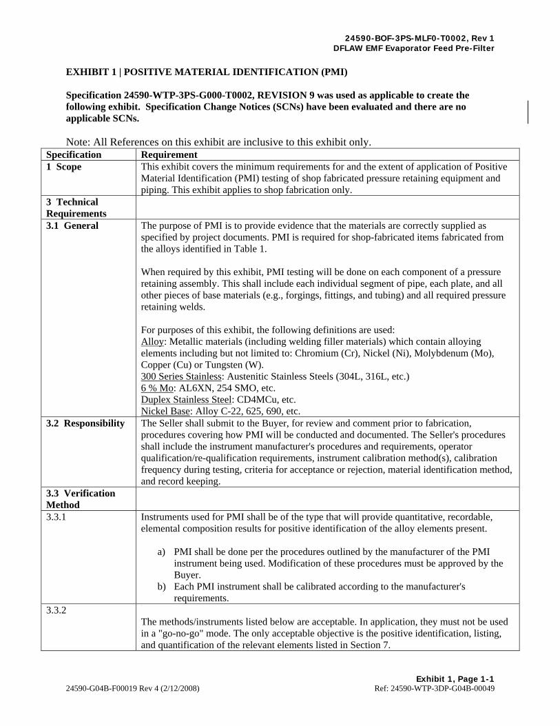
EXHIBIT 1 | POSITIVE MATERIAL IDENTIFICATION (PMI) Specification 24590-WTP-3PS-G000-T0002, REVISION 9 was used as applicable to create the following exhibit. Specification Change Notices (SCNs) have been evaluated and there are no applicable SCNs. Note: All References on this exhibit are inclusive to this exhibit only.
Specification Requirement 1 Scope This exhibit covers the minimum requirements for and the extent of application of Positive
Material Identification (PMI) testing of shop fabricated pressure retaining equipment and piping. This exhibit applies to shop fabrication only.
3 Technical Requirements
3.1 General The purpose of PMI is to provide evidence that the materials are correctly supplied as specified by project documents. PMI is required for shop-fabricated items fabricated from the alloys identified in Table 1. When required by this exhibit, PMI testing will be done on each component of a pressure retaining assembly. This shall include each individual segment of pipe, each plate, and all other pieces of base materials (e.g., forgings, fittings, and tubing) and all required pressure retaining welds. For purposes of this exhibit, the following definitions are used: Alloy: Metallic materials (including welding filler materials) which contain alloying elements including but not limited to: Chromium (Cr), Nickel (Ni), Molybdenum (Mo), Copper (Cu) or Tungsten (W). 300 Series Stainless: Austenitic Stainless Steels (304L, 316L, etc.) 6 % Mo: AL6XN, 254 SMO, etc. Duplex Stainless Steel: CD4MCu, etc. Nickel Base: Alloy C-22, 625, 690, etc.
3.2 Responsibility The Seller shall submit to the Buyer, for review and comment prior to fabrication, procedures covering how PMI will be conducted and documented. The Seller's procedures shall include the instrument manufacturer's procedures and requirements, operator qualification/re-qualification requirements, instrument calibration method(s), calibration frequency during testing, criteria for acceptance or rejection, material identification method, and record keeping.
3.3 Verification Method
3.3.1 Instruments used for PMI shall be of the type that will provide quantitative, recordable, elemental composition results for positive identification of the alloy elements present.
a) PMI shall be done per the procedures outlined by the manufacturer of the PMI instrument being used. Modification of these procedures must be approved by the Buyer.
b) Each PMI instrument shall be calibrated according to the manufacturer's requirements.
3.3.2 The methods/instruments listed below are acceptable. In application, they must not be used in a "go-no-go" mode. The only acceptable objective is the positive identification, listing, and quantification of the relevant elements listed in Section 7.

24590-BOF-3PS-MLF0-T0002, Rev 1 DFLAW EMF Evaporator Feed Pre-Filter
Exhibit 1, Page 1-2
24590-G04B-F00019 Rev 4 (2/12/2008) Ref: 24590-WTP-3DP-G04B-00049
Specification Requirement a) Portable X-ray fluorescence analyzers. Use is limited to the following instruments or their equivalent unless prior approval is given by the Buyer:
TN Technologies Alloy Analyzer 9266, 9277 (The Metallurgist XR) or 9288 Outokumpu X-Met 840, or X-Met 880 Niton Alloy Analyzer (800 Series) Thermo Scientific Niton XL3t Analyzer Metorex X-Met 920, X-Met 3000TA or X-Met 3000TX Metal Analyzer Innov-X Systems XT Series Analyzer Innov-X Systems Alpha 6500 Series Analyzer Innov-X Systems Delta Model DP-2000, DS-2000, or DC-200 Analyzer
b) Portable optical emission analyzers. Use is limited to the following instruments or their equivalent unless prior approval is given by the Buyer:
SpectroPort Model TP-07 or TFO-02 Outokumpu ARC-MET 900 or the New Spectrotest SpectroLab, Spectrotest and Spectrotest Jr.
Any other instrument will require Buyer's approval via the submittal process. Note: Arc strikes, if any, need not be removed.
3.3.3 In lieu of using portable instruments, chemical analysis can be performed on actual material samples. Care must be exercised while collecting samples, as contamination can be contributed by the removal tools. Sample extraction shall not weaken or reduce the functionality of the component. Laboratory analysis reports shall be traceable to the individual component from which the sample was taken (See Section 6, below).
3.3.4 Parts that are too small to be tested using an alloy analyzer are exempt from PMI testing. If such exemption is claimed, the PMI procedure shall specify the minimum part size capable of being tested.
3.4 Welding Consumable Control
In addition to PMI testing required by this exhibit, the Seller shall have in place, and implement, welding consumable material control systems that can be verified by auditing. PMI of completed pressure retaining welds is required as indicated in Table 1. Production "Run Off" weld test coupons may be used for chemical analysis checks.
4 Extent of PMI PMI shall be performed on completed equipment, or assembled parts of equipment, at such time as to ensure that only verified materials have been used in the fabrication and final assembly of components. If the assembled equipment configuration prevents PMI of any individual part, then that part shall be tested prior to assembly and be noted as such on the PMI documentation.
4.1 Vessels, Exchangers, Tanks, Filters and other Manufactured Equipment
Vessels, exchangers, and other manufactured equipment shall have PMI testing performed at the Seller's facilities. This shall include piping and components supplied as part of an equipment "package" or skid.
4.2 Shop Fabricated Piping
4.2.1 PMI is required for all piping and piping components, circumferential pressure retaining welds, and non-autogenous longitudinal welds as indicated in Tables 1 and 2. Note that to the greatest extent possible (considering minimum size restraints of the PMI analyzer), the requirements for examining tubing are equivalent to that of piping.
4.2.2 PMI is not required on autogenous welds, fillet welds, or socket welds.

24590-BOF-3PS-MLF0-T0002, Rev 1 DFLAW EMF Evaporator Feed Pre-Filter
Exhibit 1, Page 1-3
24590-G04B-F00019 Rev 4 (2/12/2008) Ref: 24590-WTP-3DP-G04B-00049
Specification Requirement 4.4 Valves and Pumps
PMI of valves and pumps is required for materials as indicated in Table 1 and piping fluid codes as indicated in Table 2.
4.5 Bulk Materials (Straight Run Piping, Fittings, Stock Valves, Etc.)
PMI is required as indicated in Table 1. Table 2 does not apply.
5 Identification 5.1 General All shop-fabricated items/pieces that have been successfully subjected to the required PMI
shall be marked. The mark shall be durable and last through transportation and receiving inspection at the Buyer's facility. See Section 7 for items that do not pass PMI.
5.2 Marking Materials
Marking materials and adhesive tape selected shall not cause corrosion or other harmful effects. Requirements for marking materials:
The total chloride/flouride content shall not exceed 200 ppm. The total sulfur content shall not exceed 400 ppm. The total of low melting point metals such as lead, zinc, copper, tin, antimony, and
mercury shall not exceed 1 percent; of this, mercury shall not exceed 50 ppm. 5.3 Equipment and Equipment Components
When it has been verified that the material has a composition consistent with the material specified, then it must be stamped with letters "PMIV". Use low stress stamps for identification. Items that cannot be stamped shall have an alternate system of marking. Heat exchanger tubing shall not be stamped. Any alternate system, and the items for which it will be used, must have Buyer approval. To the maximum extent possible, the stamping/marking shall be located for ease of future reference/verification.
5.4 Piping Materials
When it has been verified that the material has a composition consistent with the material specified, then a colored adhesive tape, or other approved marking method, shall be applied at one end to facilitate proper identification.
5.5 Fasteners and Small Parts
Fasteners and small parts shall be marked in accordance with the Seller's procedure using a hard marking method, an indelible ink, or paint.
6 Records of PMI Results shall be recorded on PMI report forms, which shall indicate, as a minimum, the following for each examination:
a) Name of inspector b) Date of testing c) Test method, including PMI instrument name and serial number d) Equipment tag number or pipe spool number (PO number for bulk items) for the
specific piece tested e) Quantitative analysis results for relevant elements (see Section 7)
A PMI map consisting of assembly and sub-assembly drawings shall be prepared for each piece of fabricated equipment or pipe spool. The map shall include components and welds and show the locations of PMI testing. An extended Shop Spool Sheet shall be provided for each individual spool number where PMI was done. In the case of bulk items, PMI results may be submitted in the form of a certificate verifying that parts were tested according to the requirements of this exhibit. Results shall be reported by heat/lot and shall include the following:
a) Name of inspector

24590-BOF-3PS-MLF0-T0002, Rev 1 DFLAW EMF Evaporator Feed Pre-Filter
Exhibit 1, Page 1-4
24590-G04B-F00019 Rev 4 (2/12/2008) Ref: 24590-WTP-3DP-G04B-00049
Specification Requirement b) Date of testing c) Test method, including PMI instrument name and serial number d) Type and number of pieces tested e) Acceptable composition ranges for the relevant elements (see Section 7) f) Material identified
PMI forms shall become a part of the permanent inspection records. Seller shall submit the completed forms as part of the Final Document Package when required by the Form G-321 -V in the Purchase Order.
7 Acceptance, Rejection and Retesting Requirements
All materials tested shall be identified by the PMI instrument as being consistent with the composition of the specified material. The results shall fall within the chemical composition requirements of the ASTM, AWS or other applicable material specification allowing for the accuracy of the instrument. Any questionable PMI result shall be re-analyzed by the same or another instrument, after verification of proper surface preparation. See Section 7.1, below, for materials and welds that fail to meet requirements on the second analysis. The following elements shall be identified and recorded, even if the instrument does provide immediate identification (e.g. display of "316", "6 Mo", etc.): Alloy Elements 304, 304L Ni, Cr 316, 316L Ni, Cr, Mo 347 Ni, Cr, Nb Duplex, 6% Mo, 254 SMO, AL6XN, etc. Ni, Cr, Mo, Cu Nickel base alloys, C-22, 625, 690, etc. Ni, Cr, Mo, W Welds joining dissimilar base materials or having filler materials that do not match the base material composition may include an allowance for dilution. Acceptable composition ranges for commonly used combinations of base material and weld filler metals are included in Table 3. Other combinations, when required, shall be identified to the Buyer for approval. Please note that the only proper use of Table 3 is for assessing dissimilar welds.
7.1 If any material, component, or weld of a type not requiring 100% testing is found to be unacceptable, all other materials, components, or welds (same heat, lot, etc.) represented by that failed item shall be considered suspect. The Buyer shall be notified immediately if a component is confirmed to have failed the PMI. The Seller will then have the following options, with Buyer concurrence:
a) Scrapping/removing all materials, components, or welds represented by the test piece (all of that heat, lot, etc.) and replacing with new components or filler metals, or
b) Performing 100 percent examination of the remainder of the represented materials, components, or welds, and replacing each item that fails the PMI check, or
c) Verifying correct chemistry by laboratory chemical analysis. 7.2 If questionable values obtained with portable analyzers are verified by laboratory analysis,
the laboratory analysis data shall be used and recorded. 7.3 Any item or component containing materials that have not passed the PMI shall be clearly
marked as "DO NOT USE — PMI FAILED" and segregated from the remainder of the stock.

24590-BOF-3PS-MLF0-T0002, Rev 1 DFLAW EMF Evaporator Feed Pre-Filter
Exhibit 1, Page 1-5
24590-G04B-F00019 Rev 4 (2/12/2008) Ref: 24590-WTP-3DP-G04B-00049
Specification Requirement Table 1 PMI Requirements for Shop Fabricated Items/Pieces
Table 1 PMI Requirements for Shop Fabricated Items/Pieces
ITEM - (NOTE 1) VERIFICATION REQUIRED
Type 304 & 304L Stainless Steel Components No Type 316, 316L, & 347 Stainless Steel Components Yes – 100% 6% Mo Components Yes – 100% Duplex Stainless Steel Components Yes – 100% Nickel Base Alloy Components Yes – 100% Alloy Valves Yes – 100% Body and Bonnet Only Alloy Pumps Yes – 100% Casing Only Alloy Piping – including non-autogenous longitudinal welds (Spools, Fittings, Straight-Run Pipe, and Tubing)
Yes – 100% for 6 % Mo alloys and Nickel base alloys Yes – 100% for 316L, used in the fluid codes listed in Table 2
Alloy Pressure Retaining Welds Yes – 100% of completed welds that join material required to have PMI testing
Bolting — B8M used for Pressure Retaining Connections
Yes – 5 % of total bolts, minimum one check per heat
Alloy Heat Exchanger Tubing Yes – 5 % of total tubes, minimum one check per heat
Venturis Yes – 100% pipes and welds Note: 1. The following items are exempted unless specifically designated for PMI by the Purchase Order:
a) All type 304L stainless steel components, piping, and welds b) Deleted c) Non pressure-retaining parts, such as baffles, trays, tray clips, supports, pall-rings,
support rings, etc. d) Non pressure-retaining welds and sections of piping, such as drains, vents,
overflows, etc. e) Gaskets f) Instrumentation (except when the instrument is a shop fabricated piping component
placed in-line of a piping system requiring PMI) g) Internal instruments parts (including pressure retaining parts) h) Instrument tubing less than 1/2 inch in diameter i) HVAC ducting j) Piping components located within piping systems for which PMI is NOT required.
Table 2 Fluid Codes Requiring PMI Testing (Shop

24590-BOF-3PS-MLF0-T0002, Rev 1 DFLAW EMF Evaporator Feed Pre-Filter
Exhibit 1, Page 1-6
24590-G04B-F00019 Rev 4 (2/12/2008) Ref: 24590-WTP-3DP-G04B-00049
Specification Requirement Fabricated Piping and Piping System Components)
Table 3 Base Material and Weld Filler Metal Composition Requirements (Wt%)
Tablel Fluid Codes Requfring PMI Testing (Shop Fabricated Piping a11d Piping System Components)
Fluid Code Flnid Code Fluid Code DR Suspect GU Nitric Acid Fume GV Vessel Vent
Radioactive Steam Radioac1ive HN Nitric Acid HR Recovered Nitric PA Radioactive
Acid Aqueous
PB LAW Feed PC HLW Frod Slurry PE Entrained Solids Concentrate
PF Cs/Tc Concentrate PH LAW Melter Feed PJ HL W Melter Feed ,
pp Ul trafilter PR Suspect PS Suspect Radioactive Penneate Radioactive Liquid Slurry
PU Suspect PV Strontium PW Radioactive Radioactive Carbonate Gas/Vapor Gas/Vaoor
PX Radioactive Slurry PZ Waste Feed RK Sodium Permanganate
ZE Plant Wash Fluid ZF Plant Washings ZH Acidic Effluent
ZJ AlkaHne Effluen t ZL Spent IX Resin ZN Neutralized Effiuent
ZR Suspect ZS Process zx Special Radioa.ctive Radioactive Decontaminant Condensate Condensate
ZY Scrubber Effluent
Table 3 Base Material and Weld Filler 1etal Composition Requirements (Wt %)
MATERIAL Cr Ni Mo Cu w Notes 304L BM 18.0- 20.0 8.0- 12.0 --- -- ---308L WFM 19.5 - 22.0 9.0 - 11.0 0.75 rnax -- -- E/ERJOSL & LT
304L Welds 18.0- 22.0 8.0 - 12.0 0.75 rnax --- --- Note I
J04LBM 18.0- 20.0 8.0- 12.0 --- -- ---J 16LBM 16.0- 18.0 10.0- 14.0 2.0 - 3.0 -- -- -
J 16L WFM 17.0 - 20.0 11.0- 14.0 2.0, - 3.0 --- --- E/ERJ16L & LT
J04U316L Welds 16.0 - 20.0 8.0- 14.0 3.0 max --- --- Note 1
304LBM 18.0 - 20 0 8.0 • 12.0 -·- ... --· J l6L BM 16.0 • 18.0 10.0. 14.0 2.0 • 3.0 ... ... JOSL WFM 19.5 - 220 9.0 - I 1.0 0.75 max --- --- E/ERJ08L & LT
304U3 l6L Welds 16.0 - 22.0 8.0 - 14.0 3.0 max --- --- Note I
J04L BM 18.0- 20.0 8.0- 12.0 --- --- ---J08L WFM 19.5 - 22.0 9.0- 11.0 0.75 max --- --- E/ER308L & LT
CD4MCuBM 24.5 • 26.5 4.75 - 6.0 1.75 · 2.25 2.75 - 3.25 ·-· J04UCD4MCu Welds 18.0- 26.5 4.75 - 12.0 2.0 max ---
Note 1 ---

24590-BOF-3PS-MLF0-T0002, Rev 1 DFLAW EMF Evaporator Feed Pre-Filter
Exhibit 1, Page 1-7
24590-G04B-F00019 Rev 4 (2/12/2008) Ref: 24590-WTP-3DP-G04B-00049
Specification Requirement Table 3 Base Material and Weld Filler Metal Composition Requirements (Wt%)
Table 3 Base Material and Weld Filler Metal Composition Requirements (Wt %) (cont.)
MATERIAL Cr Ni Mo Cu w Notes 3 16LBM 16.0 · 18.0 10.0 - 14.0 2.0-3.0 -- --316L WFM 17.0 - 20.0 11.0-14.0 2.0 - 3.0 --- -- E/ER3 16L & LT
3l6L Weld 16.0- 20.0 10.0- 14.0 2.0 - 3 0 --- -- Note 1
3 !6LBM 16.0- 18.0 10.0 • 14.0 2.0 • 3.0 ... --316L WFM 17.0-20.0 11.0-14.0 2.0 - 3.0 -- -- E/ER3 16L& LT
CD4MCuBM 24.5 - 26.5 4.75 - 6.0 1.75 - 2.25 2.75 - 3.25 --3 16UCD4MCu
16.0 • 26.5 4.75 - 16.0 1.75 - 3.0 Note I
Welds --- --
AL6XNBM 20.0 - 22.0 23.5 - 25.5 6.0- 7.0 0.75 ma,i: --
625 \VFM 20.0 • 23.0 58.0 mfo 8.0 - 10.0 0.50max -- E/ERNiCrMo-3
AL6XN\Velds 20.0 • 23.0 25.5 min 7.0-10.0 0.75 max -- No te2
C-22 BM 20.0 • 22.5 Remainder 12.5- 14.5 -· 2.5 • 3.5
CD4MCuBM 24.5 - 26.5 4.75 - 6.0 1.75 - 2.25 2.75 • 3.25 ·-C-22 WFM 20.0 • 22.5 Remainder 12.5 • 14.5 0.5 ma.x 2.5 • 3.5 E/ERNiCrMo- 10
C-22/CD4MCu 16.0- 22.5 25.0 min 10.5 • 14.5 2.5 - 4.5
Welds --
C-22BM 20.0 • 22.5 Remainder 12.5 - 14.5 --- 2.5 • 3.5
C-22 WFM 20.0- 22.5 Remainder 12.5 • 14.5 0.5 ma,x 2.5 · 3.5 E/ERNiCrMo-10
C-22 Welds 20.0- 22.5 52.0 min 12.5 - 14.5 - - 2.5 - 3.5 Note I
Alloy 625 BM 20.0 - 23.0 58.0 min 8.0 - 10.0 -- --10 304L 18.0- 20.0 8.0 - 12.0 --- --- --to 316L 16.0 - 18.0 10.0 . 14.0 2.0 - 3.0 ·-· ·-625 \VFM 20.0 • 230 55.0 min 8.0 • 10.0 0.50 max -- E/ERNiCrMo-3
Alloy 625 to 19.0 - 23.0 50.0 min 8.0 min 0.50 max --
304U3 16L Welds
AL6XN (N08367) 20.0 - 22.0 23.5 • 25.5 6.0 • 7.0 0.75 max --
BM
to 304L 18 .0 - 20.0 8.0 - 12.0 --- --- ---to 316L 16.0- 18.0 10.0- 14.0 2.0-3.0 --- --625 WFM 20.0- 23.0 55.0 min 8.0- 10.0 0.50 max --- E/ERNiCrMo-3
N08J67 to 19.0 - 23.0 25.0 min 4.0 - 10.0
304U3 16L Welds --- ---
BM = Base metal; WFM = Weld filler metal
Notes:
l. Acceptance is based on the oombined base metal and WFM spec requirements .
2. Acceptance is based on WFM spec and the expected amount of dilution for molybdenum.

24590-BOF-3PS-MLF0-T0002, Rev 1 DFLAW EMF Evaporator Feed Pre-Filter
Exhibit 2, Page 2-1
24590-G04B-F00019 Rev 4 (2/12/2008) Ref: 24590-WTP-3DP-G04B-00049
EXHIBIT 2 | STRUCTURAL DESIGN LOADS FOR SEISMIC CATEGORY IV EQUIPMENT AND TANKS Specification 24590-WTP-3PS-FB01-T0001, REVISION 6 was used as applicable to create the following exhibit. Specification Change Notices (SCNs) have been evaluated and there are no applicable SCNs. Note: All References on this exhibit are inclusive to this exhibit only.
Specification Requirement 1.1 General
This exhibit provides structural design loads for Seismic Category IV (SC-IV) equipment and tanks on the River Protection Project-Waste Treatment Plant (RPP-WTP) located at the Department of Energy (DOE) Hanford Site in Richland, Washington. The seismic categories are derived from the performance categories defined in DOE-STD-1020-94 (Ref. 2.7). The loads include dead, live, wind, fluid, earthquake, snow, ashfall, lateral earth pressure, operating pipe reaction, and thermal loads. Equipment and Tanks required to perform a nuclear safety function during and following a seismic event shall be qualified by analysis or by testing. This exhibit is to be used in combination with the Main Equipment Specification, which may include supplemental codes applicable to the specific Structure, System, or Component (SSC). Appendix B provides guidance for documenting seismic qualification. In case of conflicts between this exhibit and other technical requirements in the Main Equipment Specification, the Seller shall identify such conflicts to the Buyer in writing and obtain resolutions documented in writing. These conflicts may also include inconsistency of load definitions, conditions and combinations as specified by the referenced codes and standards.
1.2 Definitions
EQUIPMENT: Mechanical, electrical, or control system component or element that is part of a mechanical and/or electrical system. SC-IV EQUIPMENT/TANK: Equipment/Tank required to be designed for the SC-IV loads and load combinations provided in this exhibit. This may include equipment/tank: A Safety Class (SC) or Safety Significant equipment/tank that has no natural phenomena hazards (NPH) safety function. Assigned SC-IV for seismic design per the facility-specific Preliminary Documented Safety Analysis (PDSA) document or Documented Safety Analysis document, Non-safety SSC with no potential for seismic interaction with a safety SSC Non-safety SSC with a low interaction potential with a safety SC-III SSC IN-STRUCTURE ACCELERATION RESPONSE SPECTRA: The elastic response spectrum for 5 percent equivalent viscous damping

24590-BOF-3PS-MLF0-T0002, Rev 1 DFLAW EMF Evaporator Feed Pre-Filter
Exhibit 2, Page 2-2
24590-G04B-F00019 Rev 4 (2/12/2008) Ref: 24590-WTP-3DP-G04B-00049
Specification Requirement used to represent the dynamic effects of the Design Basis Ground Motion. REQUIRED RESPONSE SPECTRUM (RRS): The response spectrum of a motion for which the equipment/tank needs to be qualified by testing. The RRS is obtained multiplying by the in-structure acceleration response spectra by a factor of 1.1 . TEST RESPONSE SPECTRUM (TRS): The response spectrum of the test input motion. The TRS is developed from the actual time history of the motion of the test table. The TRS shall envelop the RRS over the frequency range for which the test is designed. REQUIRED INPUT MOTION (RIM): The input motion in terms of acceleration, velocity, and displacement expressed as a function of frequency; that a device being tested shall withstand and still perform its intended function.
2 Applicable Documents 2.1 American Concrete Institute (ACI)
ACI 318-99 Building Code Requirements for Structural Concrete and Commentary.
2.2 American Concrete Institute (ACI)
ACI 349-01 Code Requirements for Nuclear Safety related Concrete Structures and Commentary.
2.3 American Institute of Steel Construction (AISC)
AISC M016-89 Manual of Steel Construction — Allowable Stress Design, Ninth Edition.
2.4 American Society of Civil Engineers (ASCE)
Manuals and reports on Engineering Practice; No. 78, Structural Fire Protection, ASCE 1992.
2.5 American Society of Civil Engineers (ASCE)
Minimum Design Loads for Buildings and Other Structures, ASCE 7-98.
2.6 American Society for Testing and Materials (ASTM) International
Material for steel anchor bolts, ASTM F1554 grade 36, unless specified otherwise on the design drawings.
2.7 Department of Energy (DOE):
DOE-STD-1020-94 (Including Change Notice #1 dated Jan 1996) Natural Phenomena Hazards Design and Evaluation Criteria for Department of Energy Facilities.
2.8 International Conference of Building Officials (ICBO)
Acceptance Criteria for Seismic Qualification Testing of Nonstructural Components ICBO AC 156, January 2000.
2.9 International Conference of Building Officials (ICBO)
Uniform Building code, UBC-97
2.10 Institute of Electrical and Electronics Engineers (IEEE)
IEEE Std 344-1987 (R1993) IEEE Recommended Practice for Seismic Qualification of Class 1E Equipment for Nuclear Power Generating Stations.
2.12 Institute of Electrical and Electronics Engineers (IEEE)
IEEE Std 382-1996, IEEE Standard for Qualification of Actuators for Power-Operated Valve Assemblies With Safety Related Functions for Nuclear Power Plants.
2.13 Institute of Electrical and Electronics Engineers (IEEE)
IEEE Std 323-1983, IEEE Standard for Qualifying Class 1E Equipment for Nuclear Power Generating Stations.

24590-BOF-3PS-MLF0-T0002, Rev 1 DFLAW EMF Evaporator Feed Pre-Filter
Exhibit 2, Page 2-3
24590-G04B-F00019 Rev 4 (2/12/2008) Ref: 24590-WTP-3DP-G04B-00049
Specification Requirement 2.15 American Society of Mechanical Engineers (ASME)
ASME Boiler and Pressure Vessel Code, Section Il, Part D, Subpart 1 (Any edition of the code between 1995 and current edition)
4 Design Loads 4.1 Wind Loads Wind loads shall be calculated per the provisions of ASCE 7-98 (Ref.
2.5), using the following parameters: Basic wind speed (3-second gust) at a height of 33 feet above ground: 85 mph for SC-IV Exposure Category: C Importance Factor: 1.0
4.2 Snow and Ashfall Loads 4.2.1 Snow loads shall be calculated per the provisions of the ASCE 7-98
(Ref. 2.5), using 15 psf ground snow load. 4.2.2 Ashfall loads shall be as follows.
For SC-IV equipment 3 psf 4.3 Earthquake Loads 4.3.1 Earthquake loads on equipment and tanks supported by structures shall
be calculated per the provisions of UBC-97 (Ref 2.9), Section 1632, using the following parameters: Ip = 1.0 For SC-IV equipment tanks Ca = 0.24 ap = 1.0 for rigidly mounted rigid* equipment = 2.5 for flexible equipment* * and flexibly mounted rigid equipment = 1.0 for tanks * Rigid equipment are defined as those with a fundamental period of less than or equal to 0.06 seconds (≥17Hz). ** Flexible equipment are defined as those with a fundamental period of greater than 0.06 seconds (<17Hz). Rp = 3.0 To be used when equipment is attached directly to structural steel = 1.5*** To be used by suppliers unless otherwise specified on the Main Equipment Specification *** Based on actual conditions and location, Buyer's Civil, Structural, Architectural (CSA) personnel may approve an Rp of 3.0 in calculations.
4.3.2 Earthquake loads for self-supporting tanks (i.e. supported on their own foundation) shall be calculated per the provisions of UBC-97 (Ref. 2.9), Section 1634, using the following parameters: I = 1.0 for SC-IV tanks Ca = 0.24 Cv = 0.32
4.3.4 For qualification by testing (hard-mounted application), the requirements presented in either AC 156 (Ref. 2.8), or IEEE Std 344 (Ref. 2.10) shall be followed. The actual mounting of the equipment shall be either simulated or duplicated. The test duration shall be per Section 7.6.5 of IEEE Std 344. The seismic load for testing shall be defined by multiplying the In-Structure Acceleration Spectra as shown in Section 7 by a factor of 1.1, to obtain the Required Response

24590-BOF-3PS-MLF0-T0002, Rev 1 DFLAW EMF Evaporator Feed Pre-Filter
Exhibit 2, Page 2-4
24590-G04B-F00019 Rev 4 (2/12/2008) Ref: 24590-WTP-3DP-G04B-00049
Specification Requirement Spectrum (RRS) per Equation 2-6 in DOE-STD-1020-94 (Ref. 2.7) and enveloping the result to determine the Test Response Spectrum (TRS). These spectra are for horizontal input motion at 5% damping. For vertical input motion, use two-thirds of the given horizontal input motion. The Seller shall submit the proposed test program to the Buyer for review prior to testing. See Appendix D for Additional Seismic Qualification Requirements/Guidelines. To qualify by previous testing, the methodology shall be approved in advance by the Buyer, see Appendix B, section 2(k) of this exhibit for further guidance.
4.3.5 The Seller shall submit the proposed test program (test plan) to the Buyer for review prior to testing. Test plan and sequence, as referenced by IEEE Std 344 (Ref. 2.10) and IEEE Std 382 (Ref. 2.12), shall be per Sections 6.3.1.1 and 6.3.2 of IEEE Std 323 (Ref. 2.13), respectively. For qualification (line or duct-mounted application), see Appendix D.
4.5 Live Loads on Equipment-Supported and Tank-Supported Platforms and Walkways
Platforms and Walkways 100 psf Stairs treads 100 psf or 300 lbs. concentrated loads applied over an area of four (4) square inches, whichever load produces greater effect on equipment. Handrails for stairs and platforms Per Table 16B of UBC-97 (Ref. 2.9)
4.6 Thermal Loads 4.6.1 Base Temperature The base temperature for thermal analyses shall be 70oF. This
temperature is based on recommendations from ACI 349 (Ref. 2.2). 4.6.2 Outdoor Ambient Temperatures
Unless specified otherwise in the Main Equipment Specification or datasheets, ambient air temperatures shall be as follows: For SC-IV equipment:115 oF maximum, -25 oF minimum
4.6.3 Operating Temperatures (Normal and Abnormal), To
Operating (normal and abnormal) temperatures are provided in Main Equipment Specification or the Equipment Qualification Datasheets (EQDs). Abnormal Temperatures are due to an anticipated eight-hour loss of cooling event, which is postulated to occur once per year, and is not the result of an accident or NPH. Abnormal temperature thermal loads shall not be considered concurrent with earthquake (E) loads. For load combinations which include earthquake (E), To shall be normal operating temperature thermal loads only. For load combinations without seismic (E), To shall be greater of normal or abnormal operating temperature thermal loads.
24590-BOF-3PS-MLF0-T0002, Rev 1 DFLAW EMF Evaporator Feed Pre-Filter
Exhibit 2, Page 2-5
24590-G04B-F00019 Rev 4 (2/12/2008) Ref: 24590-WTP-3DP-G04B-00049
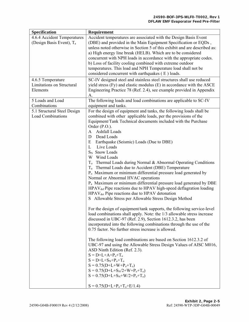
Specification Requirement 4.6.4 Accident Temperatures (Design Basis Event), Ta
Accident temperatures are associated with the Design Basis Event (DBE) and provided in the Main Equipment Specification or EQDs , unless noted otherwise in Section 5 of this exhibit and are described as: a) High energy line break (HELB). Which are to be considered concurrent with NPH loads in accordance with the appropriate codes. b) Loss of facility cooling combined with extreme outdoor temperatures. This load and NPH Temperature load shall not be considered concurrent with earthquakes ( E ) loads.
4.6.5 Temperature Limitations on Structural Elements
SC-IV designed steel and stainless steel structures shall use reduced yield stress (Fy) and elastic modulus (E) in accordance with the ASCE Engineering Practice 78 (Ref. 2.4), see example provided in Appendix A.
5 Loads and Load Combinations
The following loads and load combinations are applicable to SC-IV equipment and tanks.
5.1 Structural Steel Design Load Combinations
For the design of equipment and tanks, the following loads shall be combined with other applicable loads, per the provisions of the Equipment/Tank Technical documents included with the Purchase Order (P.O.). A Ashfall Loads D Dead Loads E Earthquake (Seismic) Loads (Due to DBE) L Live Loads SN Snow Loads W Wind Loads To Thermal Loads during Normal & Abnormal Operating Conditions Ta Thermal Loads due to Accident (DBE) Temperature Po Maximum or minimum differential pressure load generated by Normal or Abnormal HVAC operations Pa Maximum or minimum differential pressure load generated by DBE HPAVdef Pipe reactions due to HPAV high-speed deflagration loading HPAVdet Pipe reactions due to HPAV detonation S Allowable Stress per Allowable Stress Design Method For the design of equipment/tank supports, the following service-level load combinations shall apply. Note: the 1/3 allowable stress increase discussed in UBC-97 (Ref. 2.9), Section 1612.3.2, has been incorporated into the following combinations through the use of the 0.75 factor. No further stress increase is allowed. The following load combinations are based on Section 1612.3.2 of UBC-97 and using the Allowable Stress Design Values of AISC M016, ASD Ninth Edition (Ref. 2.3). S = D+L+A+Po+To S = D+L+SN+Po+To S = 0.75(D+L+W+Po+To) S = 0.75(D+L+SN/2+W+Po+To) S = 0.75(D+L+SN+W/2+Po+To) S = 0.75(D+L+Po+To+E/1.4)

24590-BOF-3PS-MLF0-T0002, Rev 1 DFLAW EMF Evaporator Feed Pre-Filter
Exhibit 2, Page 2-6
24590-G04B-F00019 Rev 4 (2/12/2008) Ref: 24590-WTP-3DP-G04B-00049
Specification Requirement S = 0.75(0.9D+Po+To±E/1.4) S = 0.75(D+L+Pa+Ta) S = 0.75(D+L+Ta+E/1.4) Where Ta is Due to HELB
5.1.1 Structural Steel Design Load Combinations for HPAV shall be consistent with Section 5.1 with the following exceptions: • HPAVdef load combinations are as follows: S = D+L+Lr+A+HPAVdef) S = D+L+SN+HPAVdef) S = 0.75(D+L+W+HPAVdef) S = 0.75(D+L+SN/2+W+HPAVdef) S = 0.75(D+L+SN+W/2+HPAVdef) • HPAVdet load combination is as follows: S = 0.75 (D+L+HPAVdet) S = 0.75(D+L+W+HPAVdet)
5.1.2 Other Loads Where other loads are to be considered in design, each applicable load shall be added to the combinations specified above per requirements of Section 1612.3.3 of UBC-97 (ref. 2.9).
5.2 Reinforced Concrete Design Load Combinations (Anchorage design)
For equipment and tanks anchorage design, the following loads shall be combined with other applicable loads, per the provisions of the Main Equipment Specification. A Ashfall Loads D Dead Loads E Earthquake Loads F Fluid Loads H Lateral Earth Pressure Load L Live Loads Ro Operating Pipe Reaction Load SN Snow Loads To Thermal Loads during Normal & Abnormal Operating Conditions W Wind Loads Ta Thermal Loads due to Accident (DBE) Temperature Po Maximum or minimum differential pressure load generated by Normal or Abnormal HVAC operations Pa Maximum or minimum differential pressure load generated by DBE U Required Strength per Strength Design Method The following load combinations are based on section 9.2 of ACI 318 (Ref. 2. l ). U = 1.4D + 1.7L + 1.7A U = 1.4D + 1.7L + 1.7SN U = 0.75(1.4D + 1.7L + 1.7W) U = 0.75 (1.4D + 1.7L + 1.7SN + 1.7W) U = 0.9D ± 1.3W U - 1.4D + 1.7L+ 1.7A + 1.7H U = 1.4D + 1.7L + 1.7SN+ 1.7H U = 0.9D + 1.7H U = 1.4D + 1.7L+ 1.7A + 1.4F U = 1.4D + 1.7L + 1.7SN + 1.4F U = 0.9D + 1.4F

24590-BOF-3PS-MLF0-T0002, Rev 1 DFLAW EMF Evaporator Feed Pre-Filter
Exhibit 2, Page 2-7
24590-G04B-F00019 Rev 4 (2/12/2008) Ref: 24590-WTP-3DP-G04B-00049
Specification Requirement U = 1.4 (D + To) In addition, the following load combinations based on UBC Section 1612.22 shall apply. U= 1.1(0.9D±E) U = 0.75(1.4D+1.7L+1.7SN+1.4Ta+1.4Ro) Where Ta is Accident (DBE) Temperature [see 4.6.4(b)] U = D+L+SN+F+H+Ta+Ro+E where Ta is due to (HELB) [see 4.6.4(a)] U = 0.75(1.4D+1.7L+1.4To+1.4Po+1.4Ro) U = 0.75(1.4D+1.7L+1.7SN+1.4To+1.4Po+1.4Ro) U = 1.4(D+To+Po) U = 1. 1 (1.2D+L+0.2SN+1.3F+1.6H+ 1.2To+1.2Po+1.2Ro+E) where To and Po are the normal operating values only U = 0.75(1.4D + 1.7L + 1.7SN+ 1.4Ta+ 1.4Pa + 1.4Ro) U = D + L + SN + F + H + Ta + Pa + Ro
6 Equipment and Tank Anchorage
The Supplier shall furnish the Buyer with the following information: • Location of anchorage in relation to equipment. • Design loads on the anchorage shall be reported by individual load and load combination. • Coordinate system and sign conventions. The selected anchor bolt material for the WTP project is ASTM F1554 (Ref. 2.6). Use of other anchor bolt materials, require the approval of the Buyer.

24590-BOF-3PS-MLF0-T0002, Rev 1 DFLAW EMF Evaporator Feed Pre-Filter
Exhibit 3, Page 3-1
24590-G04B-F00019 Rev 4 (2/12/2008) Ref: 24590-WTP-3DP-G04B-00049
EXHIBIT 3 | PRESSURE VESSEL DESIGN AND FABRICATION Specification 24590-WTP-3PS-MV00-T0001, REVISION 5 was used as applicable to create the following exhibit. Specification Change Notices (SCNs) have been evaluated and there are no applicable SCNs. Note: All References in this exhibit are inclusive to this exhibit only.
1 Scope
1.1 Project Description and Location
This exhibit is included in the Purchase Order, Material Requisition or in the scope of work of subcontract packages. It defines the technical requirements for the design, fabrication, and testing of pressure vessels for the Hanford Tank Waste Treatment and Immobilization Plant (WTP) project located in the southeastern part of Washington State.
1.2 Acronyms and Definitions
1.2.2 Containment: Components that contain active process fluids inside the plant process system. Refer to the MDS for the containment classification of components. • Primary Confinement: The boundary within which the process fluids, gases, and vapors are contained and confined during the plant process operation. In this document, the entire process vessel and nozzle walls are generally referred to as the Primary Confinement. • Primary Containment: The part of the Primary Confinement that is in contact with the process fluid. This is typically the wetted portion of the vessel wall below the top of the overflow. • Auxiliary Containment: This term is used in this document to identify the portion of a Primary Confinement that is not subject to a static pressure head of liquid but may be in contact with splashing liquid, vapor, or gases. This is typically the vessel components above the prescribed high operating liquid level. • Secondary Containment: The boundary that will contain process liquid if the Primary Containment is breached. This boundary will not normally be in contact with the process liquid. Typically, this is the cell liner or wall structure of the facility.
1.2.5 Design Level: Determines allowable nozzle reinforcement methods and nondestructive examination (NDE) requirements. Buyer assigns Design Levels on the MDS or Drawings.
1.2.6 Drawings: The Buyer’s Drawings include the vessel general outline drawing and any associated standard drawings
1.2.7 ECDS: The section of the MDS titled Equipment Cyclic Data Sheet. If components of a vessel are subjected to cyclic loads, those loads will be detailed in the ECDS.
1.2.10 MDS: The Buyer’s mechanical data sheet.
1.2.11 NDE: Nondestructive Examination
1.2.13 Quality Level: Establishes the quality assurance program requirements. Formerly, Quality Level also determined allowable nozzle reinforcement methods and NDE requirements. Refer to the Design Level for these requirements. Buyer assigns Quality Levels on the MDS or Drawings.
1.2.14 SDDR: Supplier Deviation Disposition Requests
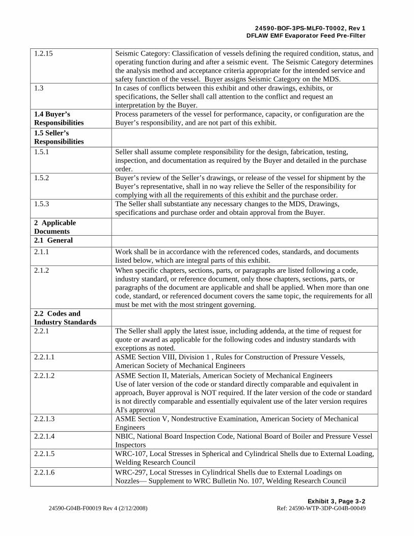
24590-BOF-3PS-MLF0-T0002, Rev 1 DFLAW EMF Evaporator Feed Pre-Filter
Exhibit 3, Page 3-2
24590-G04B-F00019 Rev 4 (2/12/2008) Ref: 24590-WTP-3DP-G04B-00049
1.2.15 Seismic Category: Classification of vessels defining the required condition, status, and operating function during and after a seismic event. The Seismic Category determines the analysis method and acceptance criteria appropriate for the intended service and safety function of the vessel. Buyer assigns Seismic Category on the MDS.
1.3 In cases of conflicts between this exhibit and other drawings, exhibits, or specifications, the Seller shall call attention to the conflict and request an interpretation by the Buyer.
1.4 Buyer’s Responsibilities
Process parameters of the vessel for performance, capacity, or configuration are the Buyer’s responsibility, and are not part of this exhibit.
1.5 Seller’s Responsibilities
1.5.1 Seller shall assume complete responsibility for the design, fabrication, testing, inspection, and documentation as required by the Buyer and detailed in the purchase order.
1.5.2 Buyer’s review of the Seller’s drawings, or release of the vessel for shipment by the Buyer’s representative, shall in no way relieve the Seller of the responsibility for complying with all the requirements of this exhibit and the purchase order.
1.5.3 The Seller shall substantiate any necessary changes to the MDS, Drawings, specifications and purchase order and obtain approval from the Buyer.
2 Applicable Documents
2.1 General
2.1.1 Work shall be in accordance with the referenced codes, standards, and documents listed below, which are integral parts of this exhibit.
2.1.2 When specific chapters, sections, parts, or paragraphs are listed following a code, industry standard, or reference document, only those chapters, sections, parts, or paragraphs of the document are applicable and shall be applied. When more than one code, standard, or referenced document covers the same topic, the requirements for all must be met with the most stringent governing.
2.2 Codes and Industry Standards
2.2.1 The Seller shall apply the latest issue, including addenda, at the time of request for quote or award as applicable for the following codes and industry standards with exceptions as noted.
2.2.1.1 ASME Section VIII, Division 1 , Rules for Construction of Pressure Vessels, American Society of Mechanical Engineers
2.2.1.2 ASME Section II, Materials, American Society of Mechanical Engineers Use of later version of the code or standard directly comparable and equivalent in approach, Buyer approval is NOT required. If the later version of the code or standard is not directly comparable and essentially equivalent use of the later version requires AI's approval
2.2.1.3 ASME Section V, Nondestructive Examination, American Society of Mechanical Engineers
2.2.1.4 NBIC, National Board Inspection Code, National Board of Boiler and Pressure Vessel Inspectors
2.2.1.5 WRC-107, Local Stresses in Spherical and Cylindrical Shells due to External Loading, Welding Research Council
2.2.1.6 WRC-297, Local Stresses in Cylindrical Shells due to External Loadings on Nozzles— Supplement to WRC Bulletin No. 107, Welding Research Council
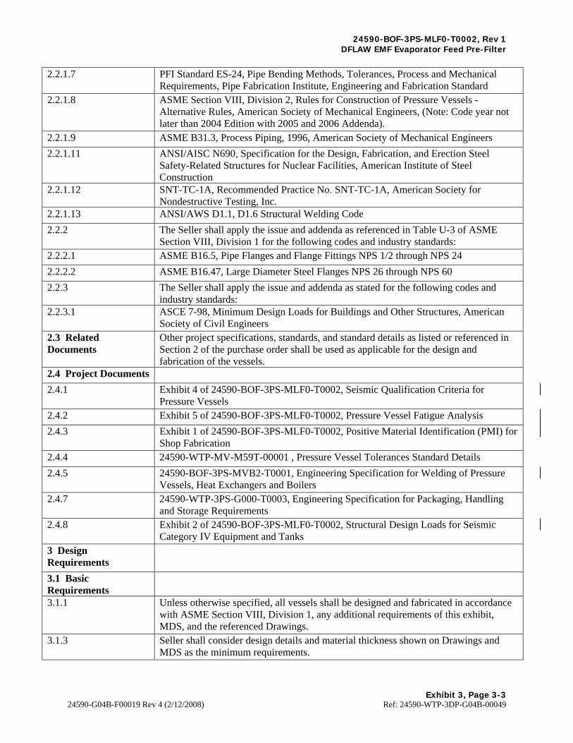
24590-BOF-3PS-MLF0-T0002, Rev 1 DFLAW EMF Evaporator Feed Pre-Filter
Exhibit 3, Page 3-3
24590-G04B-F00019 Rev 4 (2/12/2008) Ref: 24590-WTP-3DP-G04B-00049
2.2.1.7 PFI Standard ES-24, Pipe Bending Methods, Tolerances, Process and Mechanical Requirements, Pipe Fabrication Institute, Engineering and Fabrication Standard
2.2.1.8 ASME Section VIII, Division 2, Rules for Construction of Pressure Vessels - Alternative Rules, American Society of Mechanical Engineers, (Note: Code year not later than 2004 Edition with 2005 and 2006 Addenda).
2.2.1.9 ASME B31.3, Process Piping, 1996, American Society of Mechanical Engineers
2.2.1.11 ANSI/AISC N690, Specification for the Design, Fabrication, and Erection Steel Safety-Related Structures for Nuclear Facilities, American Institute of Steel Construction
2.2.1.12 SNT-TC-1A, Recommended Practice No. SNT-TC-1A, American Society for Nondestructive Testing, Inc.
2.2.1.13 ANSI/AWS D1.1, D1.6 Structural Welding Code
2.2.2 The Seller shall apply the issue and addenda as referenced in Table U-3 of ASME Section VIII, Division 1 for the following codes and industry standards:
2.2.2.1 ASME B16.5, Pipe Flanges and Flange Fittings NPS 1/2 through NPS 24
2.2.2.2 ASME B16.47, Large Diameter Steel Flanges NPS 26 through NPS 60
2.2.3 The Seller shall apply the issue and addenda as stated for the following codes and industry standards:
2.2.3.1 ASCE 7-98, Minimum Design Loads for Buildings and Other Structures, American Society of Civil Engineers
2.3 Related Documents
Other project specifications, standards, and standard details as listed or referenced in Section 2 of the purchase order shall be used as applicable for the design and fabrication of the vessels.
2.4 Project Documents
2.4.1 Exhibit 4 of 24590-BOF-3PS-MLF0-T0002, Seismic Qualification Criteria for Pressure Vessels
2.4.2 Exhibit 5 of 24590-BOF-3PS-MLF0-T0002, Pressure Vessel Fatigue Analysis
2.4.3 Exhibit 1 of 24590-BOF-3PS-MLF0-T0002, Positive Material Identification (PMI) for Shop Fabrication
2.4.4 24590-WTP-MV-M59T-00001 , Pressure Vessel Tolerances Standard Details
2.4.5 24590-BOF-3PS-MVB2-T0001, Engineering Specification for Welding of Pressure Vessels, Heat Exchangers and Boilers
2.4.7 24590-WTP-3PS-G000-T0003, Engineering Specification for Packaging, Handling and Storage Requirements
2.4.8 Exhibit 2 of 24590-BOF-3PS-MLF0-T0002, Structural Design Loads for Seismic Category IV Equipment and Tanks
3 Design Requirements
3.1 Basic Requirements
3.1.1 Unless otherwise specified, all vessels shall be designed and fabricated in accordance with ASME Section VIII, Division 1, any additional requirements of this exhibit, MDS, and the referenced Drawings.
3.1.3 Seller shall consider design details and material thickness shown on Drawings and MDS as the minimum requirements.

24590-BOF-3PS-MLF0-T0002, Rev 1 DFLAW EMF Evaporator Feed Pre-Filter
Exhibit 3, Page 3-4
24590-G04B-F00019 Rev 4 (2/12/2008) Ref: 24590-WTP-3DP-G04B-00049
3.1.4 Seller shall not scale Drawings
3.2 Loadings
3.2.1 Seismic analysis shall be performed per the requirements of Exhibit 4 of 24590-BOF-3PS-MLF0-T0002.
3.2.3 If the MDS contains an ECDS, the Seller shall analyze for fatigue per the requirements detailed in the Exhibit 5 of 24590-BOF-3PS-MLF0-T0002. Seismic loadings shall not be considered when performing a fatigue analysis.
3.2.4 Unless indicated otherwise on the MDS or Drawings, the Seller shall design the vessels to support process liquid filled to the top of the overflow.
3.3 Corrosion/Erosion Allowance
3.3.1 Corrosion allowance is specified on the MDS and shall be applied to each surface exposed to process vapor or liquid.
3.3.2 Unless otherwise specified, corrosion allowance shall not be applied to external vessel surfaces.
3.3.3 Erosion allowances, where required, will be specified in the MDS.
3.4 Heads The Seller shall use head shapes as specified on the vessel drawing. Deviations from this profile may be considered for economic, space or fabrication concerns. Any change, however, requires the approval of the Buyer via SDDR.
3.5 Supports and Anchors
3.5.1 Seller shall provide vessel supports as illustrated on the Drawings.
3.5.2 Supports and anchors shall be designed to secure the buoyant vessel in case the vessel is empty and submerged to the level indicated in the MDS.
3.5.3 Criteria Detail design of vessel supports shall be in accordance with the recommendation of ASME Section VIII, Division 1, Appendix G, except as noted below.
3.5.3.3 SC-IV stainless steel vessel supports are to be designed in accordance with the allowable stresses from N690 to the load combinations from Exhibit 2 of 24590-BOF-3PS-MLF0-T0002.
3.6 Nozzles and Manways
3.6.1 Nozzle wall thickness shall be per ASME Section VIII, Division 1 and at least that specified on the Drawings. Seller shall understand that minimum nozzle thicknesses indicated on the Drawings may not support the nozzle loading requirements listed in Appendix A.
3.6.2 Nozzles and manways and their reinforcements located on the head shall be located fully within the crown region of the head unless noted otherwise on the Drawing.
3.6.3 All nozzles shall be set-in type or through type with full penetration welds. All nozzles, which are flush with the inside surface of the vessel, shall be rounded to 1/8 inch minimum radius as shown below. Nozzles for pressure relief devices, vents, and drainage shall be flush with the inside surface of the vessel. Nozzles with internal projection in primary containment shall have an additional fillet weld between the internal projection and the inside surface of the shell or head.

24590-BOF-3PS-MLF0-T0002, Rev 1 DFLAW EMF Evaporator Feed Pre-Filter
Exhibit 3, Page 3-5
24590-G04B-F00019 Rev 4 (2/12/2008) Ref: 24590-WTP-3DP-G04B-00049
3.6.4 The following illustrates acceptable and unacceptable nozzle configurations and welding:
3.6.5 Flange boltholes shall straddle natural vessel centerlines unless otherwise specified.
3.7 Nozzle Loading
3.7.1 Unless otherwise specified, Seller shall design nozzles for the minimum nozzle design loads listed in the applicable table of Appendix A for the connected pipe size. Nozzles/shell on vessels are to be designed according to the methods of WRC-107, WRC-297 as a minimum.
Sel-ln N'onle Wllh Fu ll Penetration Weld
/
Nll<Ilo Nl!Ck
- Cc=•• Profile rii.1we1a
O!>LQll,I !.lt-lo h I ,,'lrtr•t,00 Wllol ""F.,iJuol.,..ko
I.J~lredror NctZZIHnPllt11ilf)'
CCf'lliillnm~H'U
Through Nozzle wUh Full Penetratfon Weld
Naz.De t~eck
C:Onca.oe PYofi•F1llel \~Id
H1t.11d or Shall
Opdnn.11I Thrnugh ftJnnl• fnr 1Fatlg11 ~Jlrwlr-.
Unacceptable 01..zle Connections
Sel-on Nonie with Full Penetration Weld Through Nozzle with Double Fillet Weld

24590-BOF-3PS-MLF0-T0002, Rev 1 DFLAW EMF Evaporator Feed Pre-Filter
Exhibit 3, Page 3-6
24590-G04B-F00019 Rev 4 (2/12/2008) Ref: 24590-WTP-3DP-G04B-00049
3.7.2 Appendix A lists minimum design nozzle loads by nozzle size, connecting pipe material, and Seismic Category for weight, seismic, and thermal expansion cases. The coordinate system conforms to the 'right hand rule'. Loads provided in Appendix A do not have a sign convention; Seller must ensure that the direction of load application provides the most conservative stresses at the nozzle to shell or head junction. The Y-axis is vertical and in the direction of gravity regardless of the orientation of the nozzle. Loads act at the juncture of the nozzle and shell.
3.7.3 Nozzle load combinations to be considered for Primary and Secondary Stress in the design shall be: Weight + Seismic + Operating Pressure + Thermal Load (Appendix A) Note: Thermal Loads listed in Appendix A are from the loads resulting from the restrained free end movement of the attached pipe and are considered as primary loads per paragraph 4-138 of Appendix 4 of ASME VIII Division 2. With regard to the radial load, the internal pressure shall not be used to oppose the compressive stress due to the force acting inwards; for this load condition a null pressure condition is to be considered to exist. Nozzle load combinations to be considered for Secondary Stress in the design shall be: Weight + Operating Pressure + Thermal Load (Appendix A) + General Thermal (per code definition)
3.7.4 The nozzle loads provided are for the piping connected to the external nozzle. If a nozzle projects and is loaded internally to the vessel, design the nozzle for the sum of the internal and external loads.
3.7.5 The nozzle loads due to thermal expansion listed in Appendix A are estimated based on the operating temperature of 350 °F. If the maximum operating temperature of the attached pipe is less than 350 °F, the nozzle thermal loads may be reduced by a scale factor of the absolute value. Where X is the maximum vessel operating temperature of the attached pipe.
3.8 Nozzle Reinforcement
3.8.1 When required, suitable nozzle reinforcements must be provided. Reinforcement methods are limited depending on the assigned Design Level and cell designation. Refer to Section 6 for allowable reinforcement methods. If the wall thickness of the nozzle neck is greater than that of the connecting piping, the requirements of ASME Section VIII, Division 1, and Figure UW-13.4 shall be satisfied.
3.8.2 Nozzle reinforcing pads, where permitted, shall have one-piece construction (not segments). Nozzle insert plates (integral pads) shall be in accordance with ASME Section VIII with a 3 to 1 taper.
f I X - 70 I ~ ~0-70

24590-BOF-3PS-MLF0-T0002, Rev 1 DFLAW EMF Evaporator Feed Pre-Filter
Exhibit 3, Page 3-7
24590-G04B-F00019 Rev 4 (2/12/2008) Ref: 24590-WTP-3DP-G04B-00049
3.8.3 For external nozzle reinforcing pads, the pad thickness shall not exceed 1.5 times the thickness of the penetrated shell. To meet nozzle loading requirements, pad diameter may exceed the limits of reinforcement per ASME Section VIII, Division 1. Pad width shall be at least 2 inches but shall not exceed ten times the thickness of the pad. Each pad shall have single 1/8 inch nominal pipe size (NPT) telltale hole for testing purposes. On completion of all fabrication activities, the hole shall be fitted loosely with a screwed plug of the same material as the reinforcement plate.
3.8.4 The following illustrates acceptable reinforcement practices for nozzles irrespective of Design Level:
3.8.5 Nozzles on Commercial Grade vessels may use external reinforcing pads (See figure below). As a warning, the nozzle loads specified in Appendix A may exceed the practical use of repads. In such cases, the Seller should consider locally increasing the thickness of the shell or head with an insert plate or increasing the nozzle neck thickness as required. The following illustrates acceptable reinforcing practices with full penetration welds for nozzles on Commercial Grade vessels.
3.8.6 Material used for nozzle reinforcement shall be the same as the parent vessel unless approved by the Buyer as stated on the MDS.
Insert Plate
Nozzle Reinforcement Methods for All Design levels
lnsen Plate
Nozzle Reinforcement Methods Only for Commercial Grade Vessels
Not Located in a Black Cell
Increase Nozzle e(k Thickness

24590-BOF-3PS-MLF0-T0002, Rev 1 DFLAW EMF Evaporator Feed Pre-Filter
Exhibit 3, Page 3-8
24590-G04B-F00019 Rev 4 (2/12/2008) Ref: 24590-WTP-3DP-G04B-00049
3.8.7 Structural reinforcing elements such as reinforcing rings or pads (integral or non-integral) can be used as necessary to accommodate new design load combinations on fabricated and partially fabricated vessels. Any butt-weld seams to be covered by the pads shall be ground flush and radiographically examined, in accordance with ASME Section VIII, Division 1, subdivision UW-51, before the reinforcing pads are welded in place. Reinforcing pads may be formed to the required shape by any process that will not unduly impair the physical properties of the material. Reinforcing pads shall be fitted to conform to the curvature of shell, head, or other surfaces to which they are attached to minimize flat spots and horizontal surfaces that could collect solids. Edges of non-integral pads shall be tapered 3 to 1 minimum to match the height of the legs of the attaching fillet welds. The fillet welds shall fully seal the dead space between the pad and the shell, head, or other surfaces to which the pad is attached.
3.10 External Components and Supports
3.10.1 If the MDS specifies insulation, the Seller shall provide and install insulation supports per the Drawings.
3.10.2 Lifting and tailing lugs shall be provided and installed by the Seller per the Drawings. The Seller may propose alternate designs and submit SDDR for Buyer approval prior to detail design.
3.10.3 The Seller is responsible for determining the necessity of stiffening rings. The material shall match the material of the shell and attachment welds shall be continuous on both sides of the ring. Reinforcement Pads for nozzles, guides etc., shall match the material of parent vessel.
3.10.4 If specified on the Drawings, Seller shall provide and install support clips for piping or platforms. The materials welded to the shell shall match the material of the shell.
3.10.5 If indicated on the Drawings, Seller shall provide and install grounding lugs.
3.10.7 The base of the vertical vessel support skirt shall be marked, using a line of welding bead, at the 0 degree orientation as shown on the Drawings.
3.10.8 If a separate ring beam support is specified on the vessel drawing, the top flange shall be marked, using a line of welding bead, at the 0 degree orientation as shown on the Drawings. Vendor shall include ring beam geometry in their vessel/skirt analysis and shall provide forces and moments at the bottom of ring beam at embed location/interface.
3.10.9 The external supports skirts, legs, saddle, lugs etc., shall be designed in accordance with N690 for Stainless Steel Structures. The support at the discontinuity and with vessel is within the code pressure boundary and shall be designed per ASME Section VIII.
4 Materials
4.1 General
4.1.1 Materials shall be new and free from defects. Classification of fabrication materials shall be in accordance with ASME Section II. The Seller shall furnish legible copies of the mill test reports from the manufacturer for materials comprising the Primary Confinement, internals, supports, and welded attachments. Other materials shall be provided with certified statements that the material meets the requirements of ASME Section II.
4.1.2 Material shall be furnished to the specification and grade shown on the MDS. The fabricator shall not substitute materials without written approval from the Buyer.

24590-BOF-3PS-MLF0-T0002, Rev 1 DFLAW EMF Evaporator Feed Pre-Filter
Exhibit 3, Page 3-9
24590-G04B-F00019 Rev 4 (2/12/2008) Ref: 24590-WTP-3DP-G04B-00049
4.1.3 Contact materials including marking materials, temperature indicating crayons, adhesive backed and pressure sensitive tape, and barrier and wrap materials may be used only under the following limits: • The total halogen content shall not exceed 200 parts per million (PPM) • The total sulfur content shall not exceed 400 PPM • No intentionally added low melting point metals such as lead, zinc, copper, tin, antimony, and mercury. Anti spatter compounds shall not contain chlorine, fluorine, sulfur, mercury or other low melting point metals. Materials and residue shall be completely removed when no longer required. Cleaning materials may be non-halogenated solvents or potable water containing no more than 50 PPM chloride. Contact materials shall be controlled and documented in accordance with the Seller's inspection and test plan as approved by the Buyer.
4.1.4 Seller shall maintain a positive system of identification of materials used in the fabrication of each vessel per Exhibit 1 of 24590-BOF-3PS-MLF0-T0002.
5 Fabrication
5.1 General
5.1.1 Seller shall, if necessary, provide temporary stiffening and jigging to prevent shell distortion during fabrication, welding processes, heat treatment, hydrostatic testing, or shipment.
5.1.2 Fabrication tolerances shall be in accordance with ASME Section VIII, Division 1 and standard drawing 24590-WTP-MV-M59T-00001.
5.1.3 The sequence of fabrication shall be planned to permit maximum access to the internal surfaces to enable examination of all welds.
5.1.4 Plates and pipes shall be cut to size and shape by machining, grinding, shearing, plasma, laser, or water jet cutting. Plates, 3/8 inch thick and above, cut by shearing, shall either be dye penetrant tested on the sheared edge or have 3/8 inch allowance left on the edges which shall be removed by machining or grinding. All thickness of plate or pipe cut by air plasma cutting shall have the edges dressed to a smooth, bright finish. Material cut by the inert gas shielded plasma, laser or water jet process will not require further dressing other than deburring. All lubricants, burrs, and debris shall be removed after cutting.
5.1.5 All stamps used for identification reference markings shall be of the low stress type. Stampings shall not be located near discontinuities.
5.1.6 If a butt welded seam is required between materials of different thickness, the thicker material shall normally be machined on the side away from the process liquid. Machining shall ensure a smooth finished profile with no sharp corners and shall be in accordance with ASME Section VIII, Division 1 .
5.1.7 When rolling any austenitic stainless plate, care shall be taken to prevent carbon pickup or contamination of rolled material. The work area shall be free of carbon steel grindings and general cleanliness shall be maintained to preclude carbon contamination.
5.1.8 Only stainless steel brushes, clean iron-free sand, ceramic, or stainless steel grit shall be used for cleaning stainless steel or nonferrous alloy surfaces. Cleaning tools or materials shall not have been previously used on carbon steel.
5.2 Layout

24590-BOF-3PS-MLF0-T0002, Rev 1 DFLAW EMF Evaporator Feed Pre-Filter
Exhibit 3, Page 3-10
24590-G04B-F00019 Rev 4 (2/12/2008) Ref: 24590-WTP-3DP-G04B-00049
5.2.1 Plate size shall be chosen to minimize welding. For horizontal vessels, the longitudinal seams in cylindrical shells and conical heads shall be located above the specified normal operating level, where practical. Longitudinal seams shall be completed before welding any adjoining circumferential seam.
5.2.2 The longitudinal seams of adjacent shell courses shall be staggered by a minimum length (measured from the toe of the welds) of 5 times the plate thickness, or 4 inches whichever is greater. Where it is considered impractical to meet this requirement, Seller shall submit a proposed layout to the Buyer for approval via the SDDR process.
5.2.3 For large diameter formed heads, where two or more plates are butt welded prior to forming, the butt welds shall be located such that the weld in the knuckle region is minimized.
5.2.4 Saddles shall be continuously welded to the shell. Welded seams under the saddle or wear plate are not permitted. Longitudinal weld seams in the shell should not be located within 15 degrees of the horn of the saddle or wear plate.
5.2.5 Plate layouts shall be arranged so that longitudinal and circumferential weld seams clear all nozzles, manways, and their reinforcing pads to the maximum extent possible. A minimum clearance of eight times the plate thickness from the toes of the welds is required. Where it is considered impractical to meet this requirement, Seller shall submit a proposed layout of all weld joints to the Buyer for approval via the SDDR process.
5.2.6 Structural attachment welds such as internal support rings or clips, external stiffening rings, insulation support rings, and ladder, platform or pipe support clips shall clear weld seams by a minimum of 2 inches. If overlap of pad type structural attachments and weld seams is unavoidable, the portion of the seam to be covered shall be ground flush and radiographically examined before the attachment is welded. The seam shall be radiographed per ASME Section VIII, Division 1, Paragraph UW-51 for a minimum distance of 2 inches beyond the edge of the overlapping attachment. Any protrusion through the weld seam when unavoidable shall be radiographically examined after completing the joint weld for at least minimum distance of 8 times the thickness of thicker material at protrusion. Radiographic examination of longitudinal weld seams is not required when single plate edge type attachments such as tray support rings, stiffening rings, insulation support rings, ladder, platform, or pipe support clips cross such weld seams.
5.3 Nozzles, Manways, and Reinforcing Pads
5.3.1 For forged nozzles connecting to pipe of lesser wall thickness, the Seller shall prepare the nozzles per ASME Section VIII, Division 1, Figure UW-13.4.
5.3.3 Nozzles to be butt welded to connecting pipe shall be prepared for field welding and fitted with a plastic or rubber protective cover and sealed to prevent dirt and water from entering the vessel using adhesive tape which meets the contact material requirements.
5.4 Welding Requirements
5.4.1 Seller shall comply with 24590-BOF-3PS-MVB2-T0001.
5.4.2 All welding shall be continuous. Stitch welding is prohibited.
5.4.3 Joints shall be assembled and retained in position for welding. The use of manipulators or other devices to permit welding in the flat position should be employed where practical.

24590-BOF-3PS-MLF0-T0002, Rev 1 DFLAW EMF Evaporator Feed Pre-Filter
Exhibit 3, Page 3-11
24590-G04B-F00019 Rev 4 (2/12/2008) Ref: 24590-WTP-3DP-G04B-00049
5.4.4 All attachments such as lugs, brackets, nozzles, pads and reinforcements around openings and other members (when permitted) shall follow the contour and shape of the surface to which they will be attached. The gap at all exposed edges to be welded shall not exceed the greater of 1/16 inch or 1/20 of the thickness of the attachment at the point of attachment.
5.4.5 Where fillet welds only are used, the maximum gap between the components being joined shall be 1/8 inch. The components shall be clamped or otherwise maintained together during welding.
5.4.6 Attachment point of spiders, braces, or other temporary attachments shall match the material of the vessel.
5.4.7 All temporary attachments shall be removed prior to shop hydrotest unless specifically approved by the Buyer.
5.4.8 Where practical, internal structural components and piping welds shall be full penetration. If it is not practical, seller shall propose fillet welded attachments for Buyer approval via the SDDR process.
6 Design and NDE Requirements
6.1 All Design Levels
6.1.1 The shell and head sections which are subjected to concentrated or large loads through welded attachments (such as lifting and tailing lugs) shall, prior to welding, be ultrasonically examined over 100 percent of the areas, in accordance with the following: • For connections or attachments directly welded to the shell or head, the area tested shall extend 3 inches beyond the extremity of the proposed weldment • For connections or attachments welded via a reinforcement or doubler plate, the shell area tested shall extend 5 inches beyond each side of the perimeter of the proposed fillet weld attaching the reinforcing or doubler plate to the shell or head • Not required for nozzle penetrations.
6.1.2 All full penetration welds attaching internal or external structural components to the heads or shell shall be ultrasonically tested. If fillet welds except for Lifting and Tailing Lugs are permitted by writing by the Buyer and are not readily ultrasonically tested, they may be dye penetrant tested or magnetic particle tested with approval from the Buyer via the SDDR process.
6.1.3 All full penetration welds forming part of the jacket shall be ultrasonically tested.
6.1.4 Records of the NDE and other tests shall be submitted to the Buyer as described in the purchase order.
6.1.6 Additional NDE requirements are specified in the drawings and MDS.
6.4 Additional Requirements for Commercial Grade (CM) Vessels
6.4.1 Nozzles may use either a pad or integral reinforcement.

24590-BOF-3PS-MLF0-T0002, Rev 1 DFLAW EMF Evaporator Feed Pre-Filter
Exhibit 3, Page 3-12
24590-G04B-F00019 Rev 4 (2/12/2008) Ref: 24590-WTP-3DP-G04B-00049
6.4.2 The following weldments shall be subject to volumetric testing unless otherwise indicated on the MDS or Drawings: • At least 10 percent of the length of each welder's production of vessel main seams butt welds. The minimum extent of volumetric testing shall include all "T" junctions and 10 percent of the remaining longitudinal weld with a 6 inch minimum length of volumetric testing. • For nozzle-to-shell welds located in the Primary Containment, at least 10 percent of the number of welds made by each welder over 100 percent of its circumference. • At least 10 percent of butt welds in internal piping for the full circumference. Radiography is the preferred method of volumetric testing. Where it is considered impractical to perform radiographic examination due to joint configuration, the Seller may propose ultrasonic examinations; the seller shall use the SDDR process to propose ultrasonic examinations. The SDDR shall include UT procedure reference, technical justification of UT proposal for every weldment and schematic location of every weldment proposed to be UT tested.
7 Tests and Inspections
7.1 Hardness Testing for Austenitic Stainless Steel Components
7.1.1 Hardness testing is required when austenitic stainless steel plates are cold formed to make sections such as angles, channels, and conical sections. This requirement is not applicable to the cold forming of dished heads, which is covered by the relevant section of ASME Section VIII, Division 1.
7.1.2 Hardness testing is required when austenitic stainless steel pipe is cold formed for bends with a centerline radius less than three times the nominal pipe diameter.
7.1.3 Any cold forming process, which may significantly increase hardness, shall be in accordance with an approved procedure, which contains hardness testing. The procedure shall be submitted for Buyer's approval.
7.1.4 Hardness testing shall be performed on areas subject to the greatest deformation after cold working or any rework or rectification. The maximum permitted hardness is HRB 92 or as indicated by the material specification acceptance criteria for hardness.
7.1.5 If the maximum permitted hardness is exceeded, the Seller shall solution anneal (heat treatment) in accordance with the applicable ASME specification for that material. Heat Treatment process shall include heating and cooling rates, thermocouple locations, and type of heating equipment. Seller shall submit a written procedure for suitable heat treatment and testing for Buyer's approval.
7.2 Nondestructive Examinations
7.2.1 Radiography, ultrasonic testing, visual examination, magnetic particle, and dye penetrant examination, where specified or required, shall be performed in accordance with ASME Section VIII, Division 1 and ASME Section V, and procedures developed and submitted to the Buyer for review prior to use.

24590-BOF-3PS-MLF0-T0002, Rev 1 DFLAW EMF Evaporator Feed Pre-Filter
Exhibit 3, Page 3-13
24590-G04B-F00019 Rev 4 (2/12/2008) Ref: 24590-WTP-3DP-G04B-00049
7.2.2 All mandatory nondestructive examination (visual, surface flaw, and volumetric) shall be carried out after the completion of fabrication, including any heat treatment. Where Seller carries out additional nondestructive examination prior to any heat treatment process, such examinations shall be included in the Quality Plan or Inspection Schedule. The Buyer's representative need not witness this additional nondestructive examination; however, the records of such inspection shall be made available to the Buyer's representative.
7.2.3 Nondestructive examination must be performed by an inspector certified to the requirements of SNT-TC-1A. The interpretation of the results shall be by either Level II or Level III inspectors certified to SNT-TC-1A. Visual examination is not included in this requirement.
7.2.3.1 All weld visual examinations shall be performed by personnel certified in accordance with American Society for Non-Destructive testing (ASNT) Recommended practice SNT-TC-1A, Level I, II, or III or certified in accordance with AWS QC-1 as either a Certified Welding Inspector (CWI) or a Senior Certified Weld Inspector (SCWI)
7.2.4 Ultrasonic testing, where specified by the Buyer or proposed by the Seller, shall be in accordance with Appendix 12 of ASME Section VIII, Division 1.
7.2.5 Radiographic acceptance criteria shall be in accordance with ASME Section VIII, Division 1, Paragraph UW-51 where full radiography is required or UW-52 where spot radiography as defined in this exhibit is per Section 6.4.2.
7.2.7 Dye Penetrant testing, where specified by the Buyer or proposed by the Seller, shall be in accordance with Appendix 8 of ASME Section VIII, Division 1.
7.2.8 Magnetic Particle testing, where specified by the Buyer or proposed by the Seller, shall be in accordance with Appendix 6 of ASME Section VIII, Division 1.
7.2.9 Weld visual examination, where specified by the Buyer or proposed by the Seller, shall be in accordance with ASME Section V, Article 9.

24590-BOF-3PS-MLF0-T0002, Rev 1 DFLAW EMF Evaporator Feed Pre-Filter
Exhibit 3, Page 3-14
24590-G04B-F00019 Rev 4 (2/12/2008) Ref: 24590-WTP-3DP-G04B-00049
7.2.10 Fillet Weld Measurement: • A fillet weld leg size specified on the drawing weld symbol is the minimum size required 360 degrees around the nozzle/attachment. The effective throat based on that fillet size must be fully met around that circumference, including the obtuse (downhill) location. Both leg and throat dimensions must be met as an example, for a specified fillet weld leg size of 1/4", the throat thickness on the obtuse side as shown in the figure below is NOT acceptable (less than 0.707 x 1/4") and consequently the actual leg size must be increased on the obtuse side to meet an effective throat thickness of 0.707 x 1/4". For angles greater than 135 degrees, submit an SDDR for buyer review and approval. Fillet weld design is applicable between 60 degrees and 135 degrees (per AWS D1.1, Section 16, D1.6 Annex B) any weld outside these limits is not considered a fillet weld and shall be designed accordingly.
7.3 Hydrotests
7.3.1 If paint is specified, the vessel shall not be painted prior to the pressure test. Coating shall not be applied to external welds of items requiring leak/hydrostatic testing prior to testing.
7.3.2 All welds shall be sufficiently cleaned and free of scale or paint prior to hydrostatic testing.
7.3.3 Testing of vessels or components made of austenitic stainless steel materials shall be conducted with potable water containing no more than 50 PPM chloride.
7.3.4 For vessels of low alloy steel, before application of the test pressure, the test water and the vessel material shall be allowed to equalize to approximately the same temperature. The temperature of the pressure resisting components during the pressure test, regardless of test media, shall be at least 30 °F warmer than the minimum design metal temperature to be stamped on the nameplate, but need not exceed 120 °F.
7.3.5 The final hydrostatic test pressure shall be held for a minimum of one hour.
114=Sin
0 ruse ' i:de
Pipe
i:z.c
Acute jde
Off et ozzle Fillet Weld
Tin·oat > ,(I,_ -o ~ l/4
("" 0 .2 for 60")

24590-BOF-3PS-MLF0-T0002, Rev 1 DFLAW EMF Evaporator Feed Pre-Filter
Exhibit 3, Page 3-15
24590-G04B-F00019 Rev 4 (2/12/2008) Ref: 24590-WTP-3DP-G04B-00049
7.3.6 After completion of the hydrostatic test, the vessel shall be drained, dried, cleaned thoroughly inside and outside to remove grease, loose scale, rust, and dirt and closed as quickly as practicable. Test water shall not be in contact with austenitic stainless steel for more than 72 hours, unless treated with an appropriate biocide.
7.3.7 If field assembly or erection is involved, the final hydrostatic test shall be at the job site. The Seller or the field subcontractor shall provide the Buyer with a detailed test procedure for review and approval prior to testing.
7.3.8 A horizontal vessel shall be tested while resting on its support saddles without additional supports or cribbing.
7.3.9 Tall vertical vessels may be shop hydrotested in the horizontal position. The vessel shall be designed for vertical hydrotest loading. These vessel supports must be adequately designed to support the vessel (in accordance with the ASME code) during the hydrotest to prevent damage.
7.3.12 Seller shall submit a hydrostatic test procedure in accordance with the requirements of Section 7.3 of this exhibit and ASME Section VIII, Division 1, Paragraph UG-99 for buyer review prior to use.
7.4 Leak Tests
7.4.1 If gas or pneumatic testing is specified in the MDS, Drawings or in the purchase order, the Seller shall conduct the tests in accordance with ASME Section V. Seller shall submit a test procedure for Buyer review prior to use.
7.4.2 Reinforcing pad attachment welds and accessible surfaces of inside nozzle to vessel wall welds shall be tested for leaks with 15 PSIG dry air or nitrogen and bubble forming solution. This test shall be performed prior to the final hydrostatic or pneumatic test as applicable.
7.5 Obstruction Test
7.5.1 Seller shall ensure and document that all internals, internal piping, and jacketing are free from obstructions.
7.6 Final Inspection of Completed Vessel
7.6.1 Final inspection of the completed vessel shall be the sole responsibility of the Seller. The finished dimensions and cleanliness of the vessels shall comply with the relevant Drawings and specifications after completion of all tests.
8 Preparation and Shipment
8.1 Cleaning
8.1.1 Seller shall comply with 24590-WTP-3PS-G000-T0003.
8.1.2 If specified in the purchase order and in any event following hot working or heat treatment, the equipment shall be descaled. The procedure to be used by Seller shall be submitted for Buyer's prior approval.
8.1.3 If blast (mechanical) descaling process is specified in the purchase order for stainless steel construction, clean and iron-free glass or ceramic beads, or sand of alumina or zirconia type shall be used. The type, grade, and chemical composition of the abrasive shall be submitted for Buyer's approval prior to its use. Recycling of abrasive is prohibited. Blast cleaning shall not be used on weld metal or as a final finish on fabrications.
8.2 Packaging

24590-BOF-3PS-MLF0-T0002, Rev 1 DFLAW EMF Evaporator Feed Pre-Filter
Exhibit 3, Page 3-16
24590-G04B-F00019 Rev 4 (2/12/2008) Ref: 24590-WTP-3DP-G04B-00049
8.2.2 All flanged openings, which are not provided with a cover, shall be protected by an ASME B16.5 or B16.47 carbon steel blind flange of the same rating as the flange, a full faced rubber gasket with a minimum thickness of 1/8 inch and carbon steel bolts with stainless steel washers.
8.2.3 For internal parts, suitable supports shall be provided to avoid damage during shipment. Temporary internal bracing shall be painted yellow and a label, located near the nameplate shall state that the vessel contains temporary bracing that must be removed.
8.2.4 Small parts, which are to be shipped loose, shall be bagged or boxed and marked with the order and plant item number of the vessel.
8.3 Shipping
8.3.1 Seller shall take all necessary precautions in loading by blocking and bracing the vessel and furnishing all necessary material to prevent damage.
8.3.2 The Seller shall verify, by calculation, that the vessel and internals will withstand loads occurring during shipping for the chosen mode of transportation. The Buyer shall inform the Seller of the chosen mode of transportation
9 Documentation and Submittals
9.2 Design calculations shall include relevant ASME Section VIII, Division 1 formulas, and source paragraphs, values used in the formulas, the calculated results, and comparison with acceptable values. Where calculations are based on other than the ASME Section VIII, Division 1 formulas, the source of the formulas shall be referenced. Where a computer program is used for calculations, a brief program description shall be given, including name and version of the program. If the program is not commercially available to industry, Seller shall maintain and provide, upon request, program documentation. Calculations shall include, but not be limited to: • Code calculations • Nozzle neck calculation per UG45, average primary stress Pm across the nozzle wall • Seismic calculations including base horizontal seismic force and moment and loads for anchorage and anchor bolt design • Support calculations including empty weight, operating weight and location of center of gravity • Calculations associated with lifting and erection of the vessel • Nozzle load analysis for local and gross effect, per Section 3.7 above, or by other approved method • Design of attachments, both internal and external • Thermal and discontinuity stresses as applicable • Fatigue analysis as applicable for vessels in fatigue services

24590-BOF-3PS-MLF0-T0002, Rev 1 DFLAW EMF Evaporator Feed Pre-Filter
Exhibit 3, Page 3-17
24590-G04B-F00019 Rev 4 (2/12/2008) Ref: 24590-WTP-3DP-G04B-00049
9.2.1 Seller shall submit an Outline drawing for each item. The Outline drawing shall include the following minimum for each item: • Shell and head thickness • Head type • Vessel empty weight, test weight and shipping weight • Center of Gravity • Lifting lugs and tailing lugs • Diameter, tangent-to-tangent dimensions and appropriate support details • Nozzle, flange support locations from datum point • Nozzle schedule with nozzle marks and service conditions • All appropriate design conditions, NDE and materials of construction • Foundation/Mounting details • Installations of appropriate internals
9.3 Seller shall make a complete set of Buyer approved drawings and other documents available to the Buyer's representative at the time the quality surveillance activities are being conducted.
9.4 All records pertaining to the nondestructive examination, base materials, filler materials, fabrication, and inspection shall be traceable to the area and part inspected and is accessible for Buyer's examination.
9.5 Seller shall provide ASME Section VIII, Division 1 data reports per ASME Section VIII Division 1, Paragraph UG-120.
9.6 Seller shall submit assembly drawings and shop detail drawings for buyer's review. These drawings shall include bill of materials, weld symbol, and NDE for each weld, and parts used in vessel construction. Assembly and shop detail drawings shall also include shell and head plate layout (including nozzles) for compliance with Section 5.2 of this exhibit.
9.7 Seller shall provide a detailed description of their work inspections and tests planned during the receipt of materials, manufacturing, testing, and conformance verification activities. This shall include identification of Bechtel and supplier witness and hold points.
9.8 Seller shall supply quality records and test results in accordance with the G321 V form of the Material Requisition to include the following.
9.8.1 Document Category 16.0 – Heat Treat Reports – in accordance with section 7.1 of this exhibit. A complete record of any applicable heat treatment including charts.
9.8.2 Document Category 19.0 Ultrasonic Examination and Verification Reports - in accordance with Section 7.2.4 of this exhibit.
9.8.3 Document Category 20.0 Radiographic Examination and Verification Reports - in accordance with Section 7.2.5 of this exhibit.
9.8.4 Document Category 20.1 RT Film and Reader Sheets - Seller shall submit the original set of radiographic film with associated technique and reader sheets for radiographic tests performed. Radiographic film must be suitably packaged to preclude moisture and handing damage.
9.8.5 Magnetic Particle Examination and Verification Reports - in accordance with Section 7.2.8 of this exhibit.

24590-BOF-3PS-MLF0-T0002, Rev 1 DFLAW EMF Evaporator Feed Pre-Filter
Exhibit 3, Page 3-18
24590-G04B-F00019 Rev 4 (2/12/2008) Ref: 24590-WTP-3DP-G04B-00049
9.8.6 Document Category 22.0 Liquid Penetrant Examination and Verification Reports - in accordance with Section 7.2.7 of this exhibit.
9.8.7 Document Category 24.0 Pressure Testing and Verification Reports
Hydrostatic Leak Testing in accordance with section 7.3 of this exhibit. Gas or Pneumatic Testing in accordance with section 7.4 of this exhibit.
9.8.8 Document Category 25.0 Inspection and Verification Report
Final dimensional verifications comply with Section 7.6 of this exhibit. Visual Weld Inspections in accordance with Section 7.2.9 and 7.2.10 of this
exhibit. Hardness Test report (if applicable) in accordance with Section 7.1 of this
exhibit.
9.8.9 Document Category 26.1 Mechanical Test Report
Load testing, Obstruction documentation per Section 7.5 of this exhibit.

24590-BOF-3PS-MLF0-T0002, Rev 1 DFLAW EMF Evaporator Feed Pre-Filter
Exhibit 3, Page A-1
24590-G04B-F00019 Rev 4 (2/12/2008) Ref: 24590-WTP-3DP-G04B-00049
Appendix A-1 Minimum Nozzle Design Loads
Horizontal Shell Top Nozzle Horizontal Shell. Bottom Nozzle
~ 1----~
Vertical Shell Horizonta l Nozzle Horizontal Head Nozzle
M ,
~ 0 M,9 ~. ~o 9 F , G M' F,
( )
(
Vertical Bottom Head Nozzle Vc11ical Top Head Nozzle
~

24590-BOF-3PS-MLF0-T0002, Rev 1 DFLAW EMF Evaporator Feed Pre-Filter
Exhibit 3, Page A-2
24590-G04B-F00019 Rev 4 (2/12/2008) Ref: 24590-WTP-3DP-G04B-00049
Appendix A-2
Table A2- M inimum Nozzle Loads Due 10 Stain less Steel Piping on Vessels Designated as SC-I I. 111. and IV
Pipt· S ize Load T~·pe Fun:·('S ~loments Fx (lb) IFY (lb) tFz (lb) Mx (ft•lb) (My (ft-lb) IMZ !ft•lbl
\\'c igh1 10 16 IO I I 7 7 I in S1.:ismit· 66 44 66 92 1~7 137
Th~nnal 28 24 38 38 77 77 Wcighl 20 32 20 26 16 16
1-l/2in s~isrnic l.<8 92 138 228 3-12 342 rhennal 58 52 78 96 192 192 \Vcig,111 3-J 56 34 46 29 29
2 in Seismic H4 162 H4 398 597 597 l'hi:nn:.1I 1(14 92 138 169 337 337 Wciglu 71 11 3 71 180 11 2 11 2
3 in Seismic 491 327 491 1570 2350 2350 Thcrm:i l 209 185 278 6(,4 1330 1.130 \Vc igh1 120 1'12 120 342 214 214
-I in Seismic 834 557 834 2%0 4440 4440 ThtTmal 356 317 474 1260 2520 2520 \Vciglu 290 462 290 95 1 595 595
6 in Seismic 2025 1350 2025 8290 12400 12400 Thcrm,11 875 777 11 70 3580 7160 7160 Weight 333 534 .,.,., 1210 758 758
8 in Seismic 2360 1580 2360 10700 16000 1(,()(10 Th~rmal 1050 938 1410 4800 9590 9590 \\'eight 36 1 578 J61 2210 1380 1380
IO in Sl'ismic 2540 1690 2540 19400 29100 29100 Thermal 11 10 991 1490 8500 17000 17000 \\'eight 502 803 502 3240 2020 2020
12 in S..:ismic 3510 2340 3510 28100 42100 42 100 l'hermal 1550 1380 2070 12400 24800 24800 Wcighl 59 1 946 59 1 3870 2420 2420
14 in Sdsmic 4160 2780 4160 33900 509()0 50900 rl1~rnwl 1850 1640 2460 15000 30100 30 100 \\'l·i~hl 757 1210 757 5080 3180 3180
16 in Sci~mic 53 1(1 3540 5310 44100 66100 66 100 ·111crmal 2380 2120 3180 19800 39500 39500 \Vcighl 1200 1930 1200 819(1 5120 5120
IR in Seismic 8490 5660 8490 71500 107000 107000 'llH."rm:c,I 2<l<l0 2(,60 3<l80 25200 50300 5'1300 Weight 1280 2050 1280 8630 5400 5400
20in Seismic 8910 5940 8910 75900 114000 114000 Thermal 3660 3260 4880 31200 62400 62400 Weight 1380 2200 1380 9380 5860 5860
22 in Seismic 95 10 6340 9510 81500 122000 122000 Thermal 4420 3930 5900 37900 75800 75800 \\'eight 1600 2570 1600 11000 6870 6870
2-1 in Seismic 11 IOO 7430 I 1100 96 100 144000 144000 Thermal 5240 4660 6990 45200 90400 90400
Nole: Unless otherwise specified on the MOS utilize tbe minimum nozzle loads s pecified

24590-BOF-3PS-MLF0-T0002, Rev 1 DFLAW EMF Evaporator Feed Pre-Filter
Exhibit 3, Page A-3
24590-G04B-F00019 Rev 4 (2/12/2008) Ref: 24590-WTP-3DP-G04B-00049
Appendix A-3
Table A4- Minimum Nozzle Loads Due lo Carbon S1cc l Pi1>ing on Vesse ls Dcsigna1ed as SC-II. I l l or IV
Pip(' Size Load T~·pc.· Fore,·~ i\l omr nt, Fx llbl IFv llbl IFz llbl Mx /ft-lb) IMv (ft-l bl IMz (ft-lb)
\\'cighl 10 16 10 13 8 8 I i n Seismic (,8 46 68 110 166 166
I hcrinal 32 30 44 53 106 106 Wcighl 20 3i io 31 20 20
1- 1/2 in Sci:-,nic 140 92 140 275 412 412 ·111ermul <,8 60 90 132 2(,5 265 \\'cighl 3-1 54 34 55 3.f 34
2 in Sci!-llliC 234 156 234 480 72 1 72 1 ·1·11..,•rmal 114 100 150 232 465 465 Wcigh1 1,2 99 62 176 II 0 110
3 in Seismic 482 32 1 482 I 9 H) 2870 2&70 Thermal 231 206 308 915 1830 1830 ll'eigh1 104 167 104 335 209 209
4 in Seismic 804 536 804 3610 5420 5420 rhcrmal 3R7 344 516 1740 3480 3480 \\'<.•igh1 243 389 243 '149 593 593
6 i n Seismic 1860 1250 1860 10200 15200 15200 l hcrmnl 906 806 1110 4930 9870 9R70 Weig.hi 353 564 353 1450 903 903
8 in Sci:-mic 2690 1800 2690 13400 20200 20200 ' l'hcrm:,I 1320 1180 1770 6610 13200 13200 \\'c igh1 384 61 5 384 2600 1630 16:10
10 in Sei~rnic 2920 1950 2920 23700 35600 35600 Thermal 1450 1290 1930 11700 23~00 23400 \\'cigh1 567 908 567 4150 2590 2590
12 in Sci:-.rnic 4310 2880 4310 37100 55(,()0 55600 ·1·hcnnal 2140 1910 2860 18400 36800 36800 Weight 707 11 30 707 5400 3380 3380
14 in Si.:bmic 5380 3590 5380 48100 72200 72200 Thermal 2(,70 2380 3570 23900 47900 47900 Wcigh1 980 1570 9RO 8040 5020 5020
16, in Seismic 7450 4970 7450 71900 108000 IOROOO rl1crn1al 3700 3290 4940 35800 71500 71500 Weight 1300 2080 1300 11300 7090 7090
18 in Seismic 9890 6590 9890 102000 152000 152000 Thcrlllol 4950 4400 6600 50900 102000 102000 Wdght 1640 2(,30 1640 14900 9330 9330
20 in Seismic 12500 8320 12500 132000 198000 198000 ·n1cnnal 6300 5600 8400 6(,500 133000 13.1000 Weight 1900 3040 1900 15400 9620 9620
22 in Seismic 14400 % 10 14400 135000 203000 203000 ·n1c.·nnal 7330 6520 9770 68800 138000 138000 \l'cighl 2510 4020 25 10 24~00 15500 15500
2~ in Seismic 19000 12700 19000 217000 326000 326000 Thcnnal 9760 8680 13000 11 1000 222000 222000
Notl': Unless (itherwise specified on the MDS utiliw the minimum nozzle loads specified
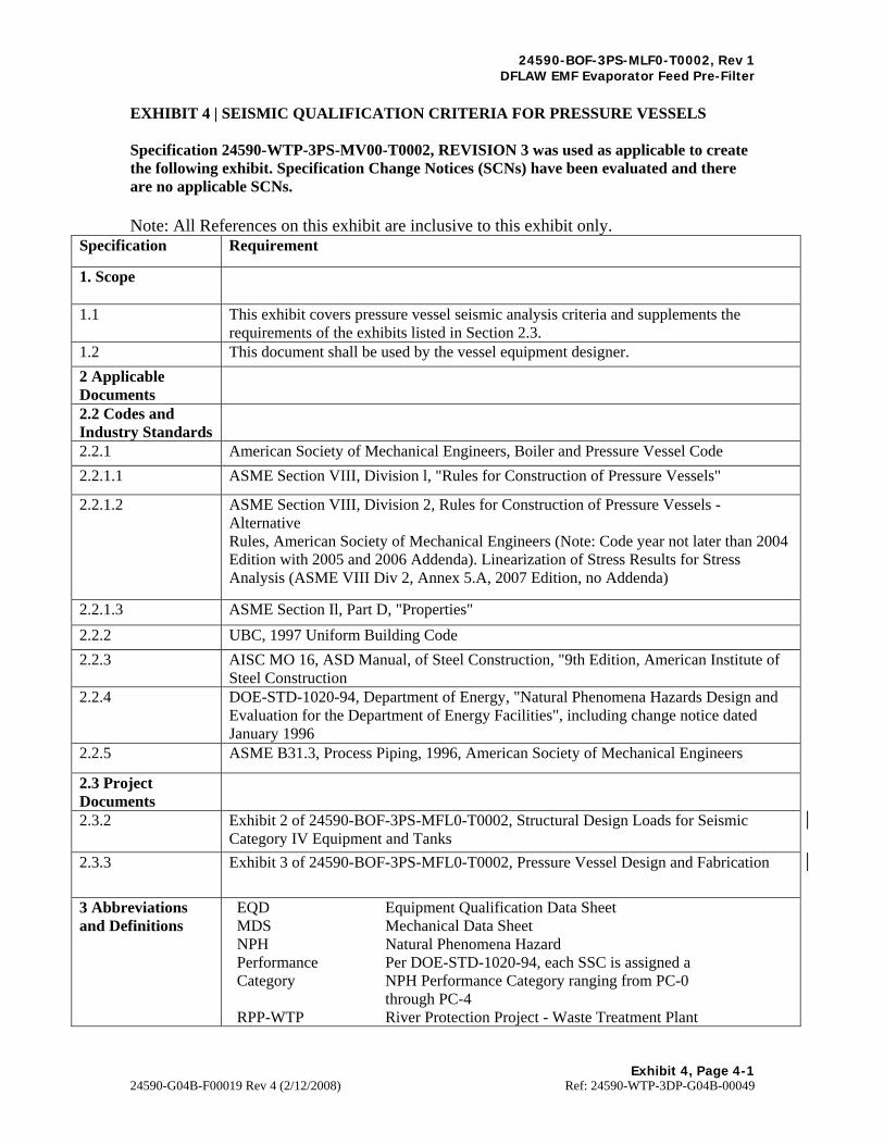
24590-BOF-3PS-MLF0-T0002, Rev 1 DFLAW EMF Evaporator Feed Pre-Filter
Exhibit 4, Page 4-1 24590-G04B-F00019 Rev 4 (2/12/2008) Ref: 24590-WTP-3DP-G04B-00049
EXHIBIT 4 | SEISMIC QUALIFICATION CRITERIA FOR PRESSURE VESSELS Specification 24590-WTP-3PS-MV00-T0002, REVISION 3 was used as applicable to create the following exhibit. Specification Change Notices (SCNs) have been evaluated and there are no applicable SCNs. Note: All References on this exhibit are inclusive to this exhibit only.
Specification Requirement
1. Scope
1.1 This exhibit covers pressure vessel seismic analysis criteria and supplements the requirements of the exhibits listed in Section 2.3.
1.2 This document shall be used by the vessel equipment designer.
2 Applicable Documents
2.2 Codes and Industry Standards
2.2.1 American Society of Mechanical Engineers, Boiler and Pressure Vessel Code
2.2.1.1 ASME Section VIII, Division l, "Rules for Construction of Pressure Vessels"
2.2.1.2 ASME Section VIII, Division 2, Rules for Construction of Pressure Vessels - Alternative Rules, American Society of Mechanical Engineers (Note: Code year not later than 2004 Edition with 2005 and 2006 Addenda). Linearization of Stress Results for Stress Analysis (ASME VIII Div 2, Annex 5.A, 2007 Edition, no Addenda)
2.2.1.3 ASME Section Il, Part D, "Properties"
2.2.2 UBC, 1997 Uniform Building Code
2.2.3 AISC MO 16, ASD Manual, of Steel Construction, "9th Edition, American Institute of Steel Construction
2.2.4 DOE-STD-1020-94, Department of Energy, "Natural Phenomena Hazards Design and Evaluation for the Department of Energy Facilities", including change notice dated January 1996
2.2.5 ASME B31.3, Process Piping, 1996, American Society of Mechanical Engineers
2.3 Project Documents
2.3.2 Exhibit 2 of 24590-BOF-3PS-MFL0-T0002, Structural Design Loads for Seismic Category IV Equipment and Tanks
2.3.3 Exhibit 3 of 24590-BOF-3PS-MFL0-T0002, Pressure Vessel Design and Fabrication
3 Abbreviations and Definitions
EQD Equipment Qualification Data Sheet MDS Mechanical Data Sheet NPH Natural Phenomena Hazard Performance Category
Per DOE-STD-1020-94, each SSC is assigned a NPH Performance Category ranging from PC-0 through PC-4
RPP-WTP River Protection Project - Waste Treatment Plant

24590-BOF-3PS-MLF0-T0002, Rev 1 DFLAW EMF Evaporator Feed Pre-Filter
Exhibit 4, Page 4-2 24590-G04B-F00019 Rev 4 (2/12/2008) Ref: 24590-WTP-3DP-G04B-00049
Specification Requirement
SC Seismic Category SC-I, II, III, IV Specifies the required seismic category of an
equipment item. Refer to Exhibit 3 for a more detailed explanation.
Seismic Loading Seismic loading is defined in terms of a site-specified design response spectrum, also referred to as Design Basis Earthquake (DBE), or specified for the site by Uniform Building Code (UBC)
SSC Structures, Systems and Components
5 Buyer's Responsibilities
5.2 The Buyer provides the Seismic Response Spectra where necessary to perform the seismic analysis.
6 Seller's Responsibilities
6.1 The Seller is responsible for the seismic analysis of the vessels according to the assigned Seismic Category. The Seller shall ensure that stresses in the vessel do not exceed those allowed, as defined in Section 7.4 for the vessel proper and reference 2.3.3 for the vessel supports, for the required loads and combinations thereof.
6.2 Depending on the Seismic Category of the vessel and its internal components, a finite element analysis may be required to determine the vessel stresses when subjected to operating and seismic loading. The software and implementation used for the analysis shall be in accordance with the quality assurance requirements defined in the purchase order.
6.3 The Seller shall obtain approval from the Buyer before nominating others to perform the design services.
7 Design Requirements
7.1 Seismic Category
7.1.1 The RPP-WTP Structures, Systems, and Components (SSC) are categorized as SC-I, II, III, or IV. The SC level is based upon the contents and the required functionality of the SSC following a seismic event. The Seismic Category defines the applicable analysis method and the acceptance criteria.
7.1.2 Seismic loading shall not be considered when performing the primary plus secondary stress range analysis required by Section VIII, Division 2, Appendix 4. In addition, seismic loading shall not be considered when performing a fatigue analysis required by Section VIII, Division 2, Appendix 5.
7.1.3 As indicated in UG-23(c), seismic loads are combined with normal operating loads when applying the factor of 1.2 to the allowable stress. Seismic loading and wind loading or Multiple Overblow need not be considered to act simultaneously.

24590-BOF-3PS-MLF0-T0002, Rev 1 DFLAW EMF Evaporator Feed Pre-Filter
Exhibit 4, Page 4-3 24590-G04B-F00019 Rev 4 (2/12/2008) Ref: 24590-WTP-3DP-G04B-00049
Specification Requirement
7.1.4 NPH Performance Categories for each SSC are assigned using criteria specified in DOE-STD-1020-94, and range from PC-0 through PC-4 depending on overall risk of the facility operation and the assigned function to the SSC. The following table summarizes the descriptions of the NPH Performance Categories as defined in DOE-STD-1020-94 and the correlation to Seismic Category:
7.2 Design Code
7.2.1 The governing design code for the vessel proper is ASME Section VIII, Division l. The loadings to be considered in designing the vessel shall include those listed in paragraph UG-22 of the code.
7.2.2 The governing design code for the vessel supports is as per Exhibit 3 of 24590-BOF-3PS-MFL0-T0002, Pressure Vessel Design and Fabrication.
7.3 Seismic Analysis
7.3.1 Internal components, supports, and piping systems shall be analyzed the same as the parent vessel unless otherwise noted. Requirements for internal piping and supports are provided in Reference 2.3.3.
7.3.3 The seismic loads for SC-III and SC-IV vessels shall be determined according to Exhibit 2 of 24590-BOF-3PS-MFL0-T0002. Factors for UBC equations are given in Section 4.0 of that exhibit.
7.3.5 The seismic analysis of SC-III and SC-IV vessels and their supports shall be performed in accordance with specification Exhibit 2 of 24590-BOF-3PS-MFL0-T0002 and 24590-WTP-3PS-MVB2-T0001.
7.4 Maximum Allowable Stresses and Acceptance Criteria for the Vessel Proper
7.4.1 Maximum Allowable Tensile Stress - The maximum allowable tensile stress, S, for the material of construction of the vessel shall be as specified in ASME Section II, Part D, and Subpart 1 .
Performance Performance Goal Description RPP-WTP Seismic Category Category (SC)
PC-0 No safety, mission, or cost considerations SC-Y
PC-I Maintain occupant safety SC-N
PC-2 Occupant safety, continued operation with minimum SC-III intenuption.
PC-3 Occupant safety, continued operation, hazard SC-II or SC-I confinement.
PC-4 Occupant safety, continued operation, confidence of ot required for this hazard confinement. project

24590-BOF-3PS-MLF0-T0002, Rev 1 DFLAW EMF Evaporator Feed Pre-Filter
Exhibit 4, Page 4-4 24590-G04B-F00019 Rev 4 (2/12/2008) Ref: 24590-WTP-3DP-G04B-00049
Specification Requirement
7.4.2 Maximum Allowable Longitudinal Compressive Stress - The maximum allowable longitudinal compressive stress used in the vessel design shall meet the requirements of paragraph UG-23(b) of the ASME Section VIII, Division 1.
7.4.3 Maximum General Primary Membrane Stress - The wall thickness of a vessel shall be determined such that the induced maximum general primary membrane stress does not exceed the maximum allowable stress in tension for any combination of loadings listed in paragraph UG-22 of ASME Section VIII, Division 1 that induce primary stresses and are expected to occur simultaneously during normal operation of the vessel.
7.4.4 Combined Primary Membrane plus Primary Bending Stress - The combination of loads as discussed in Section 7.4.3 shall not induce a combined maximum primary membrane stress plus primary bending stress across the vessel wall thickness, that exceeds 1.5 times the maximum allowable stress value in tension.
7.4.5 Combination of Seismic Loadings with Other Loadings - For the combination of seismic loading with other loadings in UG-22, the wall thickness of a vessel shall be determined such that the general primary membrane stress shall not exceed 1.2 times the permitted maximum allowable stress, as defined in 7.4.1, 7.4.2, 7.4.3 or 7.4.4. Seismic loading and wind loading or Multiple Overblow need not be considered to act simultaneously. As indicated in UG-23(c), seismic loads are combined with normal operating loads when applying the factor of 1.2 to the allowable stress. Note that ASME Section VIII, Division l, UG-23(d) is silent relative to any stresses other than General Primary Membrane, i.e., it does not address the same types of stresses (Local Primary Membrane, Primary Membrane plus Primary Bending) in the detail addressed in Section VIII, Division 2. Local Primary Membrane stress is discussed in ASME Section VIII, Division 2, Paragraph AD-140(c) and is limited to 1.5kSm, as is Primary Bending stress (AD-140(d)). Table AD-150.1 of ASME Section VIII, Division 2, then provides guidance for "k" under Design and other conditions. In accordance with that Table and in accordance with the commitment to use S vs. Sm, a factor of 1.2 times the permitted allowable stress in 7.44 above shall be used for Local Primary Membrane or Primary Bending evaluations that include seismic loading (i.e., 1.2 x 1.5 x S).
7.4.8 The acceptance criteria for non-safety vessels shall be in accordance with ASME Section VIII, Division 1, using the allowable stress, S, from ASME Section VIII, Division 1.

24590-BOF-3PS-MLF0-T0002, Rev 1 DFLAW EMF Evaporator Feed Pre-Filter
Exhibit 5, Page 5-1
24590-G04B-F00019 Rev 4 (2/12/2008) Ref: 24590-WTP-3DP-G04B-00049
EXHIBIT 5 | PRESSURE VESSEL FATIGUE ANALYSIS Specification 24590-WTP-3PS-MV00-T0003, REVISION 3 was used as applicable to create the following exhibit. Specification Change Notices (SCNs) have been evaluated and there are no applicable SCNs. Note: All References on this exhibit are inclusive to this exhibit only.
Specification Requirement
1 Introduction
1.1 This exhibit is supplementary to Exhibit 3 of 24590-BOF-3PS-MFL0-T0002 and covers fatigue evaluation and fatigue analysis requirements. The documents should be read in conjunction, particularly for definitions, conditions of conflict, and responsibilities of the parties. However, the clauses of the above document shall apply, unless specified otherwise here.
2 Definitions and Acronyms
ECDS Equipment Cyclic Data Sheet Equipment Cyclic Data Sheet
A table in the MDS which contains the cyclic data for that particular component
Fatigue Analysis Calculations to determine fatigue life expectancy of the equipment
Fatigue Evaluation A documented exercise that determines whether fatigue is a significant design criterion and must be considered by subsequent fatigue analysis
MDS Mechanical Data Sheet RPP-WTP River Protection Project – Waste Treatment Plant
3 Applicable Documents
3.1 Codes and Industry Standards
3.1.1 American Society of Mechanical Engineers Codes:
3.1.1.1 ASME Section VIII, Division 1, "Rules for Construction of Pressure Vessels".
3.1.1.2 ASME Section VIII, Division 2, Rules for Construction of Pressure Vessels - Alternative Rules, American Society of Mechanical Engineers (Note: Code year not later than 2004 Edition with 2005 and 2006 Addenda). Linearization of Stress Results for Stress Analysis (ASME VIII Div 2, Annex 5.A, 2007 Edition, no Addenda)
3.1.1.3 ASME SA 480/SA 480M, "Standard Specification for General Requirements for Flat-Rolled Stainless and Heat Resisting Steel Plate, Sheet, and Strip."
3.1.1.4 ASME B31.3, Process Piping, 1996, American Society of Mechanical Engineers.
3.1.2 American Institute of Steel Construction Standards:

24590-BOF-3PS-MLF0-T0002, Rev 1 DFLAW EMF Evaporator Feed Pre-Filter
Exhibit 5, Page 5-2
24590-G04B-F00019 Rev 4 (2/12/2008) Ref: 24590-WTP-3DP-G04B-00049
Specification Requirement
3.1.2.1 AISC M016, ASD Manual of Steel Construction, 9th Edition, American Institute of Steel Construction.
3.2 Project Documents
3.2.1 Exhibit 3 of 24590-BOF-3PS-MFL0-T0002, Pressure Vessel Design and Fabrication.
3.2.2 Exhibit 4 of 24590-BOF-3PS-MFL0-T0002, Seismic Qualification Criteria for Pressure Vessels.
4 Buyer's Responsibilities
4.1 The Buyer shall provide the necessary cyclic data for the Seller to make an evaluation regarding the fatigue life of the equipment.
5 Seller's Responsibilities
5.1 Evaluation: The Seller shall perform an evaluation of the equipment based on the cyclic data provided by the Buyer and also on any necessary data provided by others as contracted by the Seller.
5.2 Interpretation: The Seller shall confirm with the Buyer that the cyclic data has been accurately interpreted before proceeding to a fatigue analysis exercise.
5.3 Analysis: The Seller shall perform a fatigue analysis based upon the Buyer's data.
5.4 Documentation: The Seller shall provide statements and calculations for the fatigue evaluation and any analysis to the Buyer for review and approval, to support the satisfactory design life of the equipment.
5.5 Design Changes: The Seller shall make the resulting design changes to ensure the required life expectancy of equipment and subsequently obtain the Buyer's approval. The design changes shall be restricted to material thickness increases, weld types and weld seam locations. Buyer's opinion of changes shall be obtained at an early stage of the design development to ensure compliance with criteria outside the Seller's scope.
6 Fatigue Design Code
6.1 The overall design code for pressure vessels is the ASME Section VIII, Division 1 . Paragraph UG-22 (e) of Division 1, requires consideration of cyclic loading. This shall be in accordance with ASME Section VIII, Division 2 Paragraph AD-160. When fatigue analysis is required it shall be in accordance with ASME Section VIII, Division 2, Appendix 4 and 5, using the allowable stress (S) from ASME Section VIII, Division 1 in lieu of design stress intensity (Sm) of ASME Section VIII, Division 2.
7 Cyclic Load Data
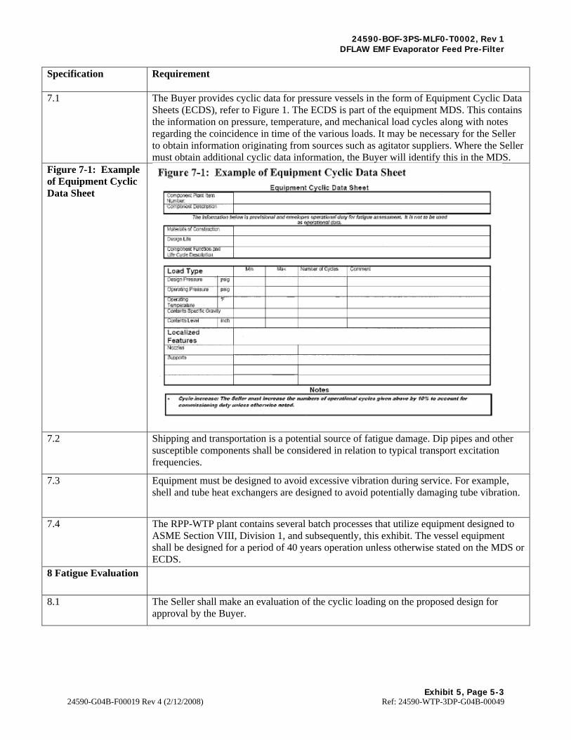
24590-BOF-3PS-MLF0-T0002, Rev 1 DFLAW EMF Evaporator Feed Pre-Filter
Exhibit 5, Page 5-3
24590-G04B-F00019 Rev 4 (2/12/2008) Ref: 24590-WTP-3DP-G04B-00049
Specification Requirement
7.1 The Buyer provides cyclic data for pressure vessels in the form of Equipment Cyclic Data Sheets (ECDS), refer to Figure 1. The ECDS is part of the equipment MDS. This contains the information on pressure, temperature, and mechanical load cycles along with notes regarding the coincidence in time of the various loads. It may be necessary for the Seller to obtain information originating from sources such as agitator suppliers. Where the Seller must obtain additional cyclic data information, the Buyer will identify this in the MDS.
Figure 7-1: Example of Equipment Cyclic Data Sheet
7.2 Shipping and transportation is a potential source of fatigue damage. Dip pipes and other susceptible components shall be considered in relation to typical transport excitation frequencies.
7.3 Equipment must be designed to avoid excessive vibration during service. For example, shell and tube heat exchangers are designed to avoid potentially damaging tube vibration.
7.4 The RPP-WTP plant contains several batch processes that utilize equipment designed to ASME Section VIII, Division 1, and subsequently, this exhibit. The vessel equipment shall be designed for a period of 40 years operation unless otherwise stated on the MDS or ECDS.
8 Fatigue Evaluation
8.1 The Seller shall make an evaluation of the cyclic loading on the proposed design for approval by the Buyer.
Figure 7-1: Example of Equipment Cyclic Data Sheet
II ~f:"rnn~~n
I
Egulement cicliic Data. Slleet
I G:¢il;<loii1'-~<Jf)
rn,e Ji,_ ll<m J);;loW i:! 1:,i,w;.,.,,w f,i1t/ ,.,~_. o;oorn,loool <l~Tf fitn'llr".q;tm! _.._..,.,llli!lfL II •• rlo r ro M <Bild ~ M•-fll'll'JOI~• ...
~\--~ Oor"1m:t.'m
~,;r,tM L"OIT:ll'llll!rf. ,i.aoon :tr» ur..affl' .c...,.,aUo,1
Load rwie T"'4> .... , r<"...,.,..q, ")= .:;o.,,-..,µ
Cla>".w,nl't......, 1'3'9
~,~ ~-... ~
............ t" J,-,,"""'IIJra L,AB'"l l:tCl!t~pa;:::::t;._..,iilH1!1
lallf~ Lf!"#&t fl-· L ocall:Z.tHI l"aaturci.s, N«sz5oo
~
Note~ . &y-DU,.lac.llYIYS Tho $eJJorn141:!IJ J'~•~· IJM ~ of 11p,u.rrt1,maJ &<yc/c.:I' 11i.v:cn ~li"t" by -tr:. to, .KCIHl"t far .11.tuJ~_l.iMJ,lit!} duly m•Nn .. : ,atiw.,w,&:., natadl.

24590-BOF-3PS-MLF0-T0002, Rev 1 DFLAW EMF Evaporator Feed Pre-Filter
Exhibit 5, Page 5-4
24590-G04B-F00019 Rev 4 (2/12/2008) Ref: 24590-WTP-3DP-G04B-00049
Specification Requirement
8.2 The evaluation is a procedure to identify equipment that may not require a full fatigue analysis. The details of this calculation, the assumptions made, and the effects from mechanical loads, shall be submitted for Buyer approval.
8.3 Following rules of ASME Section VIII apply:
8.3.2 All pressure vessels with greater than 1 million cycles (106) shall be considered as having a significant number of cycles and shall require fatigue analysis in accordance with ASME Section VIII, Division 2, Appendix 5.
8.3.3 All pressure vessels with internal components subject to fatigue cycles due to hydrodynamic loading from fluid mixing shall require a fatigue evaluation using the Section VIII, Division 2, paragraph AD 160.2 and AD 160.3 exemption rules, to determine if the number of loading cycles is significant. If a detailed fatigue analysis is required, it shall be performed in accordance with ASME Section VIII, Division 2, Appendix 5.
8.4 The equipment must not have the features described in AD-160.1 unless specific agreement is obtained from the Buyer. The requirements of AD-100 (b) that are necessary for the evaluation and analysis to be applicable shall be observed.
8.5 The liquid static head pressure affecting the stress at any location of interest shall be considered, in addition to other loads.
8.6 Non-safety pressure vessels require a fatigue evaluation in accordance with Section VIII, Division 1, Paragraph UG-22(e).
9 Fatigue Analysis
9.2 The thickness of corrosion allowance shall be completely removed from components when determining stress levels.
9.3 The fatigue analysis for all cyclic loads identified on the ECDS shall demonstrate that the maximum cumulative usage factor, 'U', does not exceed 1.0 at any critical location or discontinuity on the vessel wall such as near nozzles, supports, and structural attachment.
9.4 Seismic loading shall not be considered (see reference 3.2.2) when performing a fatigue analysis.
9.5 The acceptance criteria for fatigue analysis of pressure vessels is as follows:
9.6 The acceptance criteria for non-safety vessels shall be considered in accordance with ASME Section VIII, Division 1,UG-22 (e), using the allowable stress, S, from ASME Section VIII, Division 1 .

24590-BOF-3PS-MLF0-T0002, Rev 1 DFLAW EMF Evaporator Feed Pre-Filter
Exhibit 5, Page 5-5
24590-G04B-F00019 Rev 4 (2/12/2008) Ref: 24590-WTP-3DP-G04B-00049
Specification Requirement
9.7 For non-pressure components outside the scope of ASME Section VIII, e.g., agitator (with gear box and electric motor) mounted on vessels; other fatigue analysis techniques are acceptable, as approved by the Design Authority.
10 Surface Finishes
10.1.1 The equipment surface finish assumed for a fatigue analysis shall not exceed 2B plate mill finish in accordance with ASME SA 480/SA 480M.
10.1.2 Surface finish enhancements for cleaning or inspection purposes are not to be assumed to enhance fatigue life.
10.1.3 Local contour dressing of welds for fatigue life improvement shall not be acknowledged in any fatigue analysis. However, where the fabrication code tolerates any undercut at a weld toe this shall be acknowledged in fatigue analysis as an additional stress concentration unless fabrication and inspection procedures confirm that undercut is not present or has been repaired.
10.1.4 Welds should be assumed to be descaled as-laid for fatigue analysis purposes. The finish of welds must be full throat thickness with a blended form at the parent metal.
11 Nozzle Loads
11.1.1 The minimum nozzle design loads in the applicable table of Exhibit 3 of 24590-BOF-3PS-MFL0-T0002, Appendix A shall be used for analysis unless other loads have been specified in the MDS, in which case the MDS specified loads are to be used. The seismic component of loads shall be ignored in fatigue analysis as the seismic design is based on a single design basis event making negligible contribution to the fatigue life. The thermal and weight component of loads shall be considered in the analysis.
11.1.2 The maximum peak stress intensity range values from the combination of all piping loads, pressure, and temperature at a nozzle shall be used for fatigue analysis. If maximum values from different locations are combined then this must be identified in the calculations.
11.1.3 If the vessel has internal piping, the loads listed in the applicable table of Exhibit 3 of 24590-BOF-3PS-MFL0-T0002, Appendix A (or in the applicable MDS) shall be combined with the loads calculated by the Seller for the reaction of the internal piping on the attached nozzle.
12 Documentation
12.1 The ASME, Section VIII, Division 1, UG-22 requirement, for the consideration of cyclic loads, must be addressed by a fatigue evaluation and, where required, a fatigue analysis. This must be documented and submitted for the Buyer's approval prior to commencement of fabrication.
12.2 Typical evaluation documents shall contain: - An appraisal of the equipment cyclic duty data and the locations that are sensitive to fatigue - Histograms of the load cycles assumed for the evaluation - The calculation of the evaluation criteria values - The conclusions, assumptions and limitations of the evaluation - Supporting references

24590-BOF-3PS-MLF0-T0002, Rev 1 DFLAW EMF Evaporator Feed Pre-Filter
Exhibit 5, Page 5-6
24590-G04B-F00019 Rev 4 (2/12/2008) Ref: 24590-WTP-3DP-G04B-00049
Specification Requirement
12.3 Typical analysis documents shall contain the following as a minimum: - The stress derivations, classifications and combinations considered as cyclic - The cumulative usage factor at each critical location analyzed for fatigue - The conclusions, assumptions and limitations of the analysis - Supporting references

24590-BOF-3PS-MLF0-T0002, Rev 1 DFLAW EMF Evaporator Feed Pre-Filter
Exhibit 6, Page 6-1 24590-G04B-F00019 Rev 4 (2/12/2008) Ref: 24590-WTP-3DP-G04B-00049
EXHIBIT 6 | DELETED
24590-BOF-3PS-MLF0-T0002, Rev 1 DFLAW EMF Evaporator Feed Pre-Filter
Exhibit 7, Page 7-1
24590-G04B-F00019 Rev 4 (2/12/2008) Ref: 24590-WTP-3DP-G04B-00049
EXHIBIT 7 | DELETED

24590-BOF-3PS-MLF0-T0002, Rev 1 DFLAW EMF Evaporator Feed Pre-Filter
Exhibit 8, Page 8-1
24590-G04B-F00019 Rev 4 (2/12/2008) Ref: 24590-WTP-3DP-G04B-00049
EXHIBIT 8 | DELETED