engineering – materials and technology - leaving...
TRANSCRIPT

Coimisiún na Scrúduithe Stáit State Examinations Commission
Leaving Certificate 2013
Marking Scheme
Higher Level
ENGINEERING – Materials and Technology
v2

Note to teachers and students on the use of published marking schemes
Marking schemes published by the State Examinations Commission are not intended to be standalone documents. They are an essential resource for examiners who receive training in the correct interpretation and application of the scheme. This training involves, among other things, marking samples of student work and discussing the marks awarded, so as to clarify the correct application of the scheme. The work of examiners is subsequently monitored by Advising Examiners to ensure consistent and accurate application of the marking scheme. This process is overseen by the Chief Examiner, usually assisted by a Chief Advising Examiner. The Chief Examiner is the final authority regarding whether or not the marking scheme has been correctly applied to any piece of candidate work. Marking schemes are working documents. While a draft marking scheme is prepared in advance of the examination, the scheme is not finalised until examiners have applied it to candidates’ work and the feedback from all examiners has been collated and considered in light of the full range of responses of candidates, the overall level of difficulty of the examination and the need to maintain consistency in standards from year to year. This published document contains the finalised scheme, as it was applied to all candidates’ work. In the case of marking schemes that include model solutions or answers, it should be noted that these are not intended to be exhaustive. Variations and alternatives may also be acceptable. Examiners must consider all answers on their merits, and will have consulted with their Advising Examiners when in doubt. Future Marking Schemes Assumptions about future marking schemes on the basis of past schemes should be avoided. While the underlying assessment principles remain the same, the details of the marking of a particular type of question may change in the context of the contribution of that question to the overall examination in a given year. The Chief Examiner in any given year has the responsibility to determine how best to ensure the fair and accurate assessment of candidates’ work and to ensure consistency in the standard of the assessment from year to year. Accordingly, aspects of the structure, detail and application of the marking scheme for a particular examination are subject to change from one year to the next without notice.

Page 1
LEAVING CERTIFICATE 2013
MARKING SCHEME Written Examination and Practical Examination
ENGINEERING – MATERIALS AND TECHNOLOGY
HIGHER LEVEL

Page 2
LEAVING CERTIFICATE
ENGINEERING - Materials and Technology
(Higher Level – 300 marks)
Written Examination Marking Scheme 2013
Answer Question 1, Sections A and B and Four other questions.
Question 3 – 50 marks
(a) (i) 4 + 4 (ii) 8
(b) (i) 2 + 2 + 2 + 2 + 2 (ii) 8
(c) Any two @ 8 + 8
Question 4 – 50 marks
(a) Any two @8 + 8
(b) (i) 8 (ii) 3 + 3 (iii) 4
(c) (i) 8 (ii) 8
Question 5 – 50 marks
(a) Any three @ 6 + 6 + 6
(b) (i) 4 (ii) 4 (iii) 8
(c) Any one@16
OR
(c) (i) (ii)
4 + 4 4 + 4
Question 6 – 50 marks
(a) (i) 6 (ii) 6 (iii) 4
(b) Any three @ 6 + 6 + 6
(c) (i) 2 + 2
(ii) 2 + 2 (iii) 4 + 4
Question 7 – 50 marks
(a) 6 + 6 + 6
(b) (i) 10 (ii) 2 + 2 + 2
(c) 16
OR
(c) (i) 4 + 4 (ii) 4 + 4
Question 8 – 50 marks
(a) Any one @ 16
(b) Any three@6 + 6 + 6
(c) 16
OR
(c) (i) 4 + 4 (ii) 4 + 4
Question 1 Section A – 50 marks Any ten @ 5 marks each.
(a) Any two @ 3 + 2 (b) Any two @ 3 + 2 (c) Any two @ 3 + 2 (d) Any two @ 3 + 2 (e) 5 (f) 5 (g) 5 (h) 5 (i) 2 + 2 + 1 (j) 5 (k) 5 (l) Any two @ 3 + 2 (m) 5
Question 1 Section B – 50 marks Answer all of the following.
(n) 4 + 3 + 3
(o) (i) 1 + 1 + 1 (ii) 7
(p) 5 + 5
(q) 10
(r) Any two @5 + 5
Question 2 – 50 marks
(a) (i) 4 + 3 (ii) 3 + 3 + 3
(b) Graph 10 (i) 4 (ii) 4
(c) (i) 2 + 2 + 2 (ii) 2 + 8

Page 3
Question1 (100 Marks) Section A – 50 marks (a) Oil, grease, graphite
3 + 2
(b) Safety signs: (i) Emergency exit (ii) Ear protection (iii) Fire equipment
(Any two) 3 + 2 (c) Two ore dressing methods: Magnetic separation, flotation, gravity concentration
(Any two) 3+2
(d) Acid rain, moisture, oxygen in air (Any two) 3+2
(e) Metal alloys are combinations of metals that are mixed together, examples are solder
which is made from lead and tin. Co-polymers are formed when two different mers are linked together in the same polymer chain. Both alloys and co-polymers seek to improve material properties.
5
(f) Thermostatic control is a system that seeks to maintain a fixed temperature. Temperature is measured and additional heat is only added if the temperature drops, this preserves energy as heat is only generated if needed.
5 (g) Narcotic effects are the result of inhalation of toxic substances which can result in
loss of sensibility, drowsiness, unconsciousness and possibly death. Systemic effects are the result of toxins entering the bloodstream or body system through skin, mouth, etc. and attacking fundamental organs and functions.
5
(h) (i) Nicolaus Otto The German inventor of the first internal-combustion engine to efficiently burn fuel directly in a piston chamber.
(ii) Frank Whittle This British engineer patented the basic design for the turbojet engine in 1930. The principles of his jet engine were used in British, German and American aircraft during World War II.
(iii) Dugald Clerk Scottish engineer who designed the world's first successful two-stroke engine in 1878 and patented it in England in 1881. 5
Sample Answers and Marking Scheme
Note: The solutions presented are examples only. All other valid solutions are acceptable and are marked accordingly.

Page 4
(i) Common applications for pneumatic control include: • Automatic doors on trains and buses; • Truck brakes; • Wheel and tyre changing; • Dentist drill; • Paint spraying; • Assembly line moving of objects by pushing, pulling, clamping, etc. • Punching and pressing sheet materials; • Hazardous environments such as mines, ignitable gases, etc.
(Any three) 2 + 2 + 1 (j) Anodising
In the case of aluminium, the anodising process forms a layer of aluminium oxide which is very hard, relatively inert, electrically insulatingand can absorb dyes to colour the film. Anodizing increases corrosion resistance and wear resistance, and provides better adhesion for paint primers and glues than the bare metal.
5 (k) Carburising flame Contains an excess of acetylene with a lower oxygen supply.
(02 : C2 H2 = 0.85 to 0.95) Used for brazing, soldering, flame hardening.
5
(l) (i) IC – Integrated Circuit (ii) LCD – Liquid Crystal Display (iii) GRP – Glass-Reinforced Plastic (iv) CAM – Computer Aided Manufacture/Machining
(Any two) 3 + 2 (m) Worm and worm wheel.
5 Section B – 50 marks (n) Three heat sources: gas, light, heat, electromagnetic radiation, semiconductor, etc
4 + 3 + 3 (o) (i) A – Hot region
B – Cold region C – Regenerator
1 + 1 + 1
bright inner cone Acetylene feather
envelope

Page 5
(ii) Principle of operation: The alpha Stirling engine contains two power pistons in separate cylinders, one hot and one cold. The hot cylinder is situated inside the high temperature heat exchanger and the cold cylinder is situated inside the low temperature heat exchanger. The working fluid in the Stirling engine goes through four stages cooling, compression, heating and expansion. This is done in the alpha Stirling engine by moving the working fluid to the cooling cylinder and then through the regenerator to the heating cylinder. The change in temperature will cause the pressure of the working fluid to change and the movement of the pistons will also change the pressure.
7 (p) Engine efficiency: Stirling engine efficiency = Desired output of engine x 100 Required input of engine 1
This ideal efficiency for a Stirling engine is the highest possible efficiency of any heat engine. The car engine is approx. 25% efficient, less than half the possible efficiency of the Stirling engine.
Advantages:
• Any available heat source can be used • Can be used to produce power, heating or cooling. • Silent in operation • Low emissions • Simple design – can be lightweight and portable. • Can be manufactured to very small sizes as it is not feature internal combustion.
Disadvantages: • Low power to weight ratio • Requires a significant differential between the hot and cold zones to maintain
efficiency
• Power output is difficult to regulate
Range of applications: Advantages:
Stirling engines have been used for a wide range of applications including: • Automotive engines • Electric vehicles • Aircraft engines • Marine engines • Electrical power generation • Solar power generation • Nuclear power • Heating and cooling • Stirling cryocoolers • Heat pumps • Portable refrigeration

Page 6
• Low temperature difference engines • Acoustic Stirling Heat Engine • Chip cooling • Can be used for domestic, industrial and military applications • Stirling engines offer potential as a part of hybrid systems where slow starting
can be addressed.
Disadvantages: • Not self-starting • Require a longer warm up time than other engines.
5 + 5 (q) This Stirling engine takes heat from the processor to power the engine which then
drives a fan to cool the processor. It is self-regulating, as the more heat generated by the chip, the more power output from the Stirling engine to cool the processor.
10
(r) (i) Beta Stirling engine: A beta Stirling has a single power piston arranged within the same cylinder on the same shaft as a displacer piston. The displacer piston is a loose fit and does not extract any power from the expanding gas but only serves to shuttle the working gas between the hot and cold heat exchangers. When the working gas is pushed to the hot end of the cylinder it expands and pushes the power piston. When it is pushed to the cold end of the cylinder it contracts and the momentum of the machine, usually enhanced by a flywheel, pushes the power piston the other way to compress the gas.
(ii) Lower power output compared to internal combustion engine of same size.
Stirling engines are more expensive than internal combustion engines with same power output.
Stirling engines are not self-starting.
Stirling engines require a longer warm up time than other engine types.
It is difficult to vary the power output of Stirling engines. (iii) The role of the displacer in a Stirling engine The displacer is unique to Stirling engine design. Heat is applied to one end of the
displacer cylinder and extracted at the opposite end. The function of the displacer is to move air from the heated place to the cool place.
(Any two) 5 + 5
flywheel
hot region
displacer

Page 7
Question 2 (50 Marks) (a) (i) Metal fatigue is failure due to on/off loading or cyclic stressing. Fatigue failure begins as a minute crack which grows under the action of fluctuating stress. Creep is the slow deformation of a material over time resulting from a constant force acting on the material. Creep is more likely to occur if materials are subjected to high temperatures.
4 + 3
(ii) A - Tensile test Tests the strength of metals to see how they will react to forces exerted. It gives a measure for ductility, elasticity and can indicate brittleness. B - Vickers test A hardness test to determine the resistance to indentation. C - Izod test A test for toughness which is a measure of the resistance to impact.
3 + 3 + 3
(b) Draw graph
10
(i) U.T.S. = Max. Load = 108 = 1.38kN/mm2 C.S.A π x 52
4
(ii) 0.1% proof stress 0.1% of 50mm = 0.05mm Proof load = 88kN 0.1% proof stress = Proof Load = 88 = 1.12kN/mm2 C.S.A π x 52
4
Loa
d (
kN
)
Extension (mm) 0.05 0.25 0.5 0.75 1.0 1.25
120
100 88 80
60
40
20

Page 8
(c) (i) Non-destructive tests are used in industrial engineering to ensure:
• that parts can be tested for quality; • that expensive components need not be destroyed during testing; • tests can be carried out for flaws at surface level or internally.
2 + 2 + 2
(ii) Eddy current testing
Eddy current tests are most effective for testing non-ferrous metals of uniform section.
A coil, energised with high frequency alternating current, is placed close to a conductive material producing eddy currents on the material. A magnetic field is produced in the test specimen by the currents. A defect will distort this magnetic field which will then be located by a search coil which records electronically and displays the imperfection.
(Name and Describe) 2 + 8
Question 3 (50 Marks) (a) (i) A has been subject to annealing which is likely to make the screwdriver blade
soft, it will deform when torque is applied. B has been hardened but is still brittle. It is likely to crack or break as torque is applied.
4 + 4
(ii) Medium carbon steel can be hardened and tempered to a reasonable extent, especially when close to 1% carbon. Higher carbon content steels will harden more effectively. Lower carbon steels may be case hardened for a hard outside layer.
If hardened, the screwdriver blade needs to be tempered to reduce brittleness. The blade is cleaned and then heated slowly and carefully until it reaches tempering temperature (220-300ºC) this is usually indicated by colour changes form straw through to blue.
8 (b) (i) A - Austenite B - Austenite and Cementite C - Ferrite and Pearlite D - Pearlite and Cementite X - Eutectoid point
2 + 2 + 2 + 2 + 2
(ii) phase change - solid austenite changes to solid pearlite composition - 0.83% carbon temperature - 723oC 8

Page 9
(c) (i) Induction hardening A coil carries high frequency currents which are induced on the surface of the component causing a rapid rise in temperature. This allows a change to austenite in the surface layers of the component. Water jets then cool the steel transforming the austenite to martensite. This leaves the outer surface hard. The frequency of the current determines the depth of heating and the depth of hardening.
(ii) Quenching media:
• Water • Oil • Brine • Air
(iii) Optical pyrometer:
A B C This pyrometer compares the intensity of light from the filament of a lamp. Current flow from the lamp can be adjusted, using a variable resistor, to match the light from the furnace – this is shown in diagram B. When the filament seems to ‘disappear’, a temperature reading can be taken. The reading in diagram A is too low and the reading in diagram C is too high.
(iv) Composition of 18% chromium and 10% nickel, commonly known as 18/10 stainless, is often used in cutlery and high quality cookware. This austenite stainless steel is the 316 grade, also called marine grade stainless, it is used primarily for its excellent resistance to corrosion.
(Any two) 8 + 8
Component – section to be hardened. Induction coils Water cooling spray

Page 10
Question 4 (50 Marks) (a) (i) Age hardening Aluminium alloyed with copper and cooled from a high temperature will increase in hardness over time at room temperature. This is due to the precipitation of CuAl2. Age hardening is a feature of a range of alloys, especially non-ferrous combinations.
(ii) Eutectic alloy: A mixture of metals that is completely soluble in the liquid state but insoluble in the solid state. The cadmium and bismuth combination is an example.
Partial solubility alloy: An alloy of two metals will dissolve in each other to a limited degree, the lead-tin alloy is an example.
(iii) Vacancy or vacant site defect: if there is an atom missing from the lattice, a distortion occurs as other atoms are forced toward the vacant space.
Interstitial: a different type of atom moves into the spaces between the atoms of the lattice. Substitutional: the structure has foreign atoms in the lattice. Distortion will be caused if these atoms are a different size.
(iv) Intermetallic compound Intermetallic compounds exist as solid phases containing two or more metallic elements and may have other non-metallic elements. Intermetallic compounds will exhibit a different crystal structure than its elements. They are generally brittle with a high melting point. An example is iron carbide or cementite.
(Any two) 8 + 8
(b) (i) Draw the thermal equilibrium diagram
8
X Y
% of metal B in alloy
Liquid
Pasty – Solid and Liquid
Liquidus line
Solidus line
Tem
per
atur
e º C
Solid
0 20 40 60 80 100
600 450 400 200

Page 11
(ii) Liquid: the two metals are soluble in each other in the liquid state. Liquidus line: the change from fully liquid to pasty state. Above the liquidus line, the alloy is liquid. This is the beginning of solidification. Solidus line: the change from pasty to solid. Below the solidus line, the alloy is cooling and solid. This is the end of solidification. Pasty: alloy is in liquid and solid form Solid: alloy is in solid form.
(Any three) 3 + 3
(iii) From the diagram: X: Liquid phase of 30% B and 70% A Y: Solid phase of 80% B and 20% A 4 (c) (i) The stages of crystal solidification of a metal from the liquid phase are known
as dendritic growth. As the metal cools, solidification starts from cells and begin to grow to form a dendrite. These have a tree-like formation with branches reaching out in all directions. Grain boundaries with solid metal crystals are formed.
8
(ii) The cooling curve for 20% Nickel shown indicates the start and end of solidification for that particular alloy, these values are transferred to the equilibrium diagram. If the information from a range of cooling curves for different combinations of the alloy is collected on one chart, a thermal equilibrium diagram is then formed.
8
Question 5 (50 Marks) (a) (i) Safety hazards associated with manual metal arc welding:
• Electric shock due to high voltages. Ensure that equipment is well maintained with cables secured and insulated properly to prevent electric shock.
• Fumes created by heating metals. Materials to be welded need to be cleaned and degreased to minimise fumes while welding. Appropriate ventilation systems should be in place.
• Hot metals. Protective clothing should be worn including leather gloves, apron, etc.
• Intense light. A good quality welding shield with darkened face plates must be worn to protect the user.

Page 12
• Protect others. Appropriate welding curtain or cubicle will ensure that others are not exposed to the UV light emitted from the welding process.
(ii) Transformer A step-down transformer is used to change the mains voltage from 220V to a suitable level (80-100V) for welding. This will provide the high current needed for welding. This type of transformer has more turns on the primary coil than the secondary coil and will induce alternating current (AC) at a lower voltage. Rectifier The rectifier changes alternating current (AC) to direct current (DC). It consists of four diodes which allows two of the diodes to conduct on each half-cycle of the AC supply.
Capacitor The capacitor is employed to provide a smooth supply of low voltage DC. (iii) Functions of the electrode coating include:
• To generate a shield of carbon dioxide gas to protect welded joints from contamination by oxygen and nitrogen in the air.
• To form a slag coating which protects the weld from oxidation and ensures a slow cooling rate for the weld, this prevents cracks and brittleness.
• Facilitates the striking action of the arc between the work and electrode.
(iv) Tungsten inert gas (TIG) welding - welding of aluminium and stainless steel
Submerged arc welding (SAW) - large scale straight line welds such as steel reinforcing beams, shipbuilding and bridge construction. Oxy-acetylene welding – fabrication and repair of automotive bodies
(Any three) 6 + 6 + 6
(b) (i) Seam resistance welding
4 (ii) Applications: commonly used in sheet metal presses and filing cabinets
4
(iii) A form of resistance welding that uses copper roller electrodes to provide a continuous run of overlapping spot welds as the current is activated at set intervals. One of the electrodes may be driven by an electric motor. The workpiece is moved between the rollers and pulses of current are supplied. Each pulse is set to last long enough to produce a spot weld. The time interval is controlled so that these spots overlap by approx. 40% of their length along the seam.
8

Page 13
(c) (i) MIG welding: A semi-automatic process. A consumable bare wire electrode is fed continuously into the weld pool area through the welding torch. An inert gas, such as Argon, creates a protective shield around the weld pool giving a fluxing action. The feed rate and flow rate of the gas are set by the operator. This allows the operator to guide the torch along the weld once the arc is generated between the electrode and the work. MIG welding does not produce a slag on the weld. (ii) Electro-slag welding is an automatic welding process used to join thicker plates(5). The gap between the plates to be welded can be quite large as it
is filled with molten metal. Water cooled copper shoes(3) prevent this molten metal escaping from the joint. The carriage, shoes and electrode(1) all move together leaving the solidified weld(4) behind.
(Any one) 16
OR (c) (i) Seam welding, spot welding, projection welding, MIG, SAW
4 + 4
(ii) Painting, circuit assembly, fabrication, placing of parts, component testing
4 + 4
electrode

Page 14
Question 6 (50 Marks) (a) (i) B - Transfer moulding.
6
(ii) Transfer moulding will mould thermoset plastics, the plug casing needs to be moulded from a thermoset material due to generation of heat. Transfer moulding gives a detailed component profile. It will produce a hard, robust component.
6
(iii) The split mould allows the component produced by injection moulding to be released from the mould. At the end of the cycle, the component can be pushed out by ejector pins and trimmed to shape. This makes injection moulding an efficient automated process.
4 (b) (i) Condensation polymerisation: Used to produce many thermosetting plastics, condensation polymerisation forms a strong primary bond with cross-links between chains. Two monomers react chemically to form a new molecule with water eliminated as a by- product. This has the effect of producing a cross-linked structure with strong primary bonds. The polymer produced cannot be re-softened, has a high tensile strength and a high melting point. Phenol formaldehyde is an example.
Addition polymerisation:
Thermoplastics, such as polyethylene, are produced by addition polymerisation. Long chainlike molecules are formed by the addition of large numbers of mers. The ethylene molecule (or mer) consists of a strong and a weak bond between the carbon atoms. A catalyst or a free radical which has an unpaired electron in its outer shell is added to the ethylene molecule. The weak bond is attached and one of its electrons is taken by the radical leaving the other free. Then the attached ethylene molecule behaves like a radical and the process is continuously repeated until termination takes place.
Addition polymerisation contains bonds held together by weak van der Waals forces which can be overcome by heat or pressure. (ii) Plasticisers are added to polymers to improve their flexibility. They achieve this by altering the forces of attraction between molecules of the polymer.
Stabilisers help prevent the degradation effects that heat, ultra-violet light and other environmental conditions place on the polymer.
(iii) Extrusion: This process is used to produce items of uniform profile such as curtain rails and plumbing pipes. Plastic granules are fed from a hopper through a die by a rotating screw. The plastic is heated in the chamber before it enters the die and cooled by air jets or water as it leaves the die.
Page 15
The extruded products can be cut into lengths or coiled. Thermoplastics such as polythene, PVC and nylon are commonly extruded.
Compression moulding: This process is suitable for thermosetting plastics. It
uses a split mould formed to the shape of the object to be moulded. The combination of heat and pressure allows a measured amount of polymer to be shaped. The polymer can be in powder or ‘slug’ form. As the mould closes, the application of heat triggers the chemical reaction of ‘cross-linking’ and the object sets (curing). The mould is opened and the object is removed. These mouldings can have a high quality finish requiring only the removal of ‘flash’.
(iv) Natural rubber is the sap from the rubber tree. It has folded polymer chains
which are bonded by weak Van der Waals forces. It is both plastic and elastic.
Synthetic rubber is rubber processed with sulphur to give cross-links between the folded chains, this is vulcanisation. A stronger bond which is more durable and less flexible than natural rubber is developed.
(Any three) 6 + 6 + 6
(c) (i) A - linear structure B - cross-linked structure
2 + 2 (ii) A - thermoplastics such as polyethylene, PVC B - thermosets such as epoxy resins
2 + 2 (iii) A - can be heated and reheated into shape, low melting point, allows for easy moulding, easily disrupted by heat, low tensile strength, ideal for recycling B - will not recycle, high melting point, high tensile strength, good thermal insulation, can withstand high temperatures without loosing rigidity, stiff and less flexible.
4 + 4
Question 7 (50 Marks) (a) (i) A centre lathe must incorporate features such as:
• Moving parts must be guarded. • Stopping controls are to be prominent and accessible. • A braking system that will stop the chuck quickly. • Minimal vibration due to robust construction.
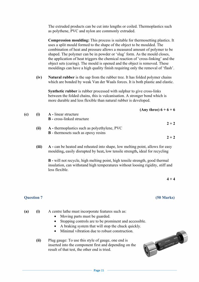
(ii) Plug gauge: To use this style of gauge, one end is inserted into the component first and depending on the result of that test, the other end is tried.

Page 16
(iii) Three types of chip formed in metal cutting: • Continuous chip, • Discontinuous chip and • Chip with built-up edge.
(iv) Methods of machining flat surfaces on metals:
• Milling; • Surface grinding; • Facing on the lathe; • CAM; • Laser cutter.
(v) Advantages: stays sharp at high temperatures, ease of replacement, multiple cutting points on each tool, cutting angles are ground into inserts Disadvantages: expensive to replace, brittle when subjected to shock load, limited use on materials other than round bars
(Any three) 6 + 6 + 6 (b) (i) Surface grinding machine:
A metal cutting process in which flat and extremely smooth surfaces are produced. The grinding wheel rotates and the workpiece, usually held in a magnetic chuck, is fed to and fro continuously. At the end of each stroke, the table is moved across the wheel by a small amount. The grinding wheel can be lowered to take a new cut.
10
(ii) Hazards using bench grinder: • All grinding processes produce small metal particles that are emitted at
high speed, eye protection is critical. • Grinding wheels rotate at high speeds, they need to be correctly
mounted and balanced to avoid vibration. • The wheels are guarded with small gaps between guard and wheel,
caution needs to be exercised as loose clothing may get trapped. • Tools and metals must be gripped close to the grinding wheels giving
the danger of metals overheating or hands slipping onto wheel. 2 + 2 + 2
grinding wheel
table
workpiece on magnetic chuck

Page 17
(c) Gang milling: This is when milling cutters are mounted side by side on the arbour. This may be used to mill a complex surface in one pass. The cutting profile is generated by the size and shape of the cutter. Straddle milling: The milling cutters are mounted on the arbour and are separated by spacing cutters. It is used to mill two surfaces parallel to each other.
16
OR (c) (i) Reducing CNC machining cycle time:
• The machine allows a rapid movement when the tool returns to start a next cutting action.
• Minimal setting-up between batch productions of components. • Multi-tool loading for components.
4 + 4
(ii) Advantages of using stepper motors in robotic control:
• Incremental movement allows for precision control of cutting. • Reliability of operation. • Good power output to give torque required for operation.
4 + 4
Workpiece
spacers
Workpiece

Page 18
Question 8 (50 Marks) (a) (i) Universal joint: The drive rotates the spline shaft of the universal joint which transmits motion through to the output shaft. This allows motion to be transmitted in a line or at an angle. It is commonly used on tractor machinery. (ii) Simple helical gear train: Two shafts are driven in opposite directions by a simple gear train. When there is no difference in gear size, both rotate at the same speed. Speeds can be varied by using different sized gears. The helical teeth on the gears allow a number of teeth on each gear to be in contact at the same time, this gives a smoother and stronger drive. These gear systems may be used on gear driven drills.
(Any one) Name 8 Operation 8
(b) (i) The advantages of toothed pulley belts: Toothed belts are much less prone to slippage. Can be used as a drive for timing engines giving a quieter operation than chain drives. (ii) Solenoid:
An electrical device where a coil of wire, wound around a soft iron core, is energised. The magnetic force induced by the current pulls the bar towards the centre. A solenoid spring will return the bar to its original position. Used for controlled entry door locks.
(iii) Resistor: A resistor will limit current flow and is used to protect electronic components. . (iv) Convert rotary motion into linear motion: Crank and slider. Rack and pinion.
(v) Pneumatic flow regulator: This restricts, or regulates, the flow of air in one direction only in a pneumatic
circuit. (Any three) 6 + 6 + 6

Page 19
(c) There are a variety of ways of providing movement to the cutter of the computer- controlled machine shown. Suggested solution - other viable solutions are acceptable.
16
(c) (i) Input components – 12V power supply, thermistor, potential divider. Output components – relay, motor.
4 + 4
(ii) The relay acts as a switch when the transistor is on. It allows the 120V circuit to activate from a 12V sensing circuit.
(Name and Describe) 4 + 4
The drive to move the cutter left and right into position and to raise and lower the cutter can be driven by rack and pinion. As the pinion rotates, the rack is driven in a linear movement. The speed of movement is determined by the rotating speed of the pinion. The rack can be driven in both directions by reversing the pinion.

Coi
mis
iún
na
Scr
úd
uit
he
Stá
it
Sta
te E
xam
inat
ion
s C
omm
issi
on
Lea
vin
g C
erti
fica
te E
ngi
nee
rin
g - P
ract
ical
Mar
kin
g S
chem
e 20
13
Subj
ectiv
e M
arki
ng 1
– 2
0
17 –
20
Exc
elle
nt
13 –
16
Ver
y G
ood
9 –
12 G
ood
5 –
8 Po
or
1 –
4 V
ery
Poor
Sec
tion
P
art
Nu
mb
er
Pic
tori
al S
ket
ch /
Des
crip
tion
C
once
pt
Mar
k
Mar
k
1 A
ll P
arts
of
Pro
ject
A
ssem
bly,
Fun
ctio
n &
Fin
ish
S
ubje
ctiv
e M
ark
1 –
20
20
20
2 P
arts
1, 3
& 4
P
art
1
8 M
arks
M
arki
ng O
ut
1 20
10 m
m R
adii
2
Dri
lled
& T
appe
d H
oles
5
Par
ts 3
& 4
12 M
arks
Mar
kin g
Out
2
24 m
m ×
17 m
m S
lots
4
Ø5.
5m
m H
oles
2
Ext
erna
l Pro
file
4 3
Par
t 2
Par
t 2
M
arki
ng O
ut
4 20
22
mm
Slo
t Pro
file
6
20 m
m R
adii
4
24 m
m B
olt E
nd R
ight
Sid
e 3
24 m
m B
olt E
nd L
eft S
ide
3 4
Par
t 5
Par
t 5
Mar
king
Out
4
20
18 m
m S
lot
4
6 m
m S
lots
4
8 m
m S
lots
4
Ext
erna
l Pro
file
4
5 P
arts
6, 7
and
8
Par
t 6
L
athe
Wor
k 4
20
Par
t 7
Lat
he W
ork
4
Par
t 8
L
athe
& B
ench
Wor
k 12
100
Mar
ks
(× 1
.5 =
150
Tot
al)
676 8
3
1 4

