engineering manual - yahoolib.store.yahoo.net/lib/yhst-19035540417790/ez42manual.pdfengineering...
TRANSCRIPT

Manufacturer of Quality Air Conditioning and Heating Products • www.islandaire.com • [email protected] • (800)-886-27591
M A N U F A C T U R E R O F Q U A L I T Y A I R C O N D I T I O N I N G A N D H E A T I N G P R O D U C T S
EZ Series 4242” W x 16”H PTAC/PTHPPerfect fit for Replacing Existing 42”X16” Units and for New Construction Projects
Engineering Manual
6140207 Rev.A

Manufacturer of Quality Air Conditioning and Heating Products • www.islandaire.com • [email protected] • (800)-886-27591
Table of ContentsTABLE OF CONTENTS ......................................1
INTRODUCTION.................................................2
APPLICATIONS New Construction ................................................3 Retrofit/Replacement ..........................................3 ApplicationConsiderations .................................4 GuaranteedQuality ..............................................4 IndoorAirQuality ...............................................4
PRODUCT OVERVIEW QuietOperation ...................................................5 DurableConstruction ...........................................5 SeacoastConstruction ..........................................5
PRODUCT FEATURES AND BENEFITS ......6,7 Identification ........................................................6 SlideOutChassis .................................................7 WallSleeve ..........................................................7 ExteriorLouver/Grilles ........................................7 RemovableFrontPanel .......................................7 DischargeGrille ...................................................7 TangentialBlowerWheel ....................................8 SlingerFan ...........................................................8 VenturiShroud .....................................................8 DischargeAirFilters ............................................8 FreshAirVent ......................................................8
DATA & SPECIFICATIONS ModelNomenclature ...........................................9 ReplacementGuide ..............................................9 PerformanceData ..............................................10 DimensionalDrawings ......................................11 ClearancesandProjections ................................12
OPTIONS AND ACCESSORIES ......................13 HardwireKit ......................................................13 PowerCord ........................................................13 OptionalTwo-StageHeater ...............................13 CondensateKit ..................................................13 Subbase ..............................................................13 LateralDuct .......................................................13
INSTALLATION INSTRUCTIONS SelectingaLocation ..........................................14 PreparingtheWallOpening ...............................15 Framing ..............................................................15 WallSleeveInstallation .....................................16 CondensateDrainKit ..................................17, 18
StampedRearGrille ..........................................19 ArchitecturalRearGrille ............................. 20-22 SubbaseAssemblyandInstallation .............23, 24 ChassisInstallation ............................................25 Frontcoverinstallation ......................................26 FreshAirVent ....................................................27 LateralDuctKit .................................................27
MAINTENANCE AirIntakeFilters ................................................28 RoutineMaintenance .........................................28
INFORMATION FOR HEAT PUMP UNITS ..29
ELECTRICAL INSTALLATION WireHarnessKit ...............................................30 HeaterlessUnits .................................................30 VoltageMeasurements .......................................30 LCDIPowerCord ..............................................30 HardwireKit ......................................................30 WiringDiagram-StandardModel ......................31
SYSTEM CONTROLS AND MANAGEMENT UserInterfaces DigitalControlPanel ....................................32 RemoteControl .............................................32 WallThermostats ..........................................32 FrontDeskControl ......................................32 SystemManagementSoftware FanCycleControl .........................................33 RoomFreezePrevention ...............................33 HighTemperatureCompressorProtection ....33 LowTemperatureCompressorProtection ....33 DiagnosticSoftware ......................................33 CustomOperationand ContinualRoomTemperatureMonitoring ....33 DigitalControlPanel ...................................34, 35 RemoteWallMountedThermostats ..................36 RemoteThermostatinterface .............................37 ControlBoardPhysicalFeatures .......................38 TemperatureLimiting ........................................39 DiagnosticDisplayErrorCodes ........................40
PERFORMANCE SPECIFICATIONS ...... 41-45
TYPICAL WARRANTY ....................................46
Islandaire reserves the right to make changes in design and construction at any time without notice.

Manufacturer of Quality Air Conditioning and Heating Products • www.islandaire.com • [email protected] • (800)-886-27592
Our CompanyIslandaire is the fastest growing specialty air conditioning and heatingmanufacturer in the country. Founded in 1992 by Robert Hansen, ithas grown into a multi-million dollar company in just a few shortyears. Islandairebuildsafullcomplementofhighquality thru-the-wallreplacementairconditionersandheatpumps,watersourceheatpumps,andgasunitsinEastSetauket,NewYork.Eachmodelfitsperfectlyintotheexistingoriginalwallsleeveassembly,therebysavingbothtimeandmoneyduringinstallations.
OurEngineering,Production,Sales andCustomerServicedepartmentshave been fully integrated to provide the maximum degree of usersatisfaction.WeatIslandairefeelthatthisteamapproachtomanufacturingproduces a superior overall product and assures a larger degree offlexibilityindesignandproductionschedulingtomeettightprototypingorconstructiontimetables.
The Perfect FitThru-wall air conditionersweredeveloped in the late1950's.Over thenextfortyyearsmanycompaniesengineered,manufacturedandinstalleda variety of different units throughout the United States and Canada.Today,anumberof thesecompaniesareno longer inbusinessorhavediscontinuedtheirlineofthru-wallairconditionersandnolongercarryreplacementparts.
Islandaire offers replacement air conditioners and heat pumps thatare interchangeable with units no longer available from the originalmanufacturer.Ourunitsareengineeredtofitperfectlywithintheexistingwall sleeve, thereby reducing installation time and expense. They aremanufacturedatourmodern75,000squarefootplantonLongIslandinNewYork.
Thankyouforconsideringourproducts,
The Islandaire Team

Manufacturer of Quality Air Conditioning and Heating Products • www.islandaire.com • [email protected] • (800)-886-27593
Applications
TheEZSeries42unitsaredesignedandmanufacturedfornewconstructionorthereplacementofpackagedterminalairconditioning(PTAC)unitsinanexistingbuilding. Our packaged terminal air conditioning(PTAC) units provide year-round comfort controlfor hotels, motels, apartments, dormitories, shops,nursinghomes,assistedlivingcenters,satelliteoffices,room additions and other applications that requireeconomicalheatingandcooling
The product is designed for individually zonedcomfort controlled heating and cooling. The unitwidth is an industry standard 42”. We offer ourcoolingchassistooperatewithcoolingonlyorelectricheat.The design standards, heavy duty constructionand the focuson indoornoise reductionhas createdourunitasthepremierunitofthefuture.Individuallycontrolled PTAC units are ideal for rooms that arenot occupied during vacancies, holidays, weekendsornights.Individualunitsallowtenantstochoosethe degreeofcomfortandoperatingeconomy.
Thermostatandfancontrolsarebuiltintothedigitaltouch-pad,plusallunitshavetheflexibilitytoconverttoawallthermostatcontrol,orinterfaceintoenergymanagement systems.Whether you are designing anewstructureorreplacingPTACunitsinanexistingbuilding,Islandairewillmeetyourneeds.
New ConstructionThe Islandaire EZ42 Packaged Terminal AirConditioning (PTAC) unit is designed to meet theneeds of the architect, engineer, and contractor. Forunit installation, Islandaire’s expert support networkwillassistinallapplicableaspectsoftheconstructionproject,frompreparingabudgettostart-up.
ADVANTAGES FOR NEW CONSTRUCTION
Design Flexibility For The Architect Engineer • Super-quietperformance,indoorsandout • Nobulkyductsystem • Noseparateequipmentroom • Nowatertowersoradditionalcooling equipment • Lesssensitivityorbuildingorientation • Optional architectural grille to permit custom exteriorappearanceLower Operating Costs & Reliable Comfort for the Occupant
Islandaire helps lower utility costs with energyefficientunitsthatexceedindustrystandards.Energysavings are achieved in both heating and coolingenvironments through efficient mechanical designand onboard electronic logic. Separate indoor andoutdoor fans provide lower operating costs. Energymanagementsoftwareisbuiltintotheunit’sstandarddigitalcontrols.
These units may also qualify for electrical powercompanyrebates.(Consultyourlocalutilityproviderforrebateopportunities.)
Retrofit/ ReplacementIslandairePTACunitsareengineeredtofitperfectlywithinmost existing wall sleeves, thereby reducinginstallationtimeandexpense.Thereisnotimewastedonredesigninganexistingwallopeningorremovinganoldwallsleeve.JustslidetheoldchassisoutandreplacewithanewonefromIslandaire.
EZ Quick slide-out chassis eases installation intothewall sleeve. Rapid servicing reduces downtime:completechassiscanbereplacedinminuteswithoutdisruptingotheroccupants.

Manufacturer of Quality Air Conditioning and Heating Products • www.islandaire.com • [email protected] • (800)-886-27594
Applications (cont.)
Application
ConsiderationsIt is important for air conditioning systems to beproperlysizedforeachapplicationinordertoachievedesiredtemperatureandhumiditylevels.ItisstronglyrecommendedthataprofessionalengineermatchthePTACunitswiththebuildingstructureandclimate.
The following application considerations are allimportantinchoosingtheproperPTACsystemforthebuildingstructure.
UNDERSIZING
IfaPTACunitisundersized(coolingcapacityislessthan required capacity for an application), the unitwillnotbeabletocoolthespacedowntothedesiredtemperatureduringveryhotdays.
OVERSIZING
IfaPTACunitisoversized(coolingcapacityisgreaterthanrequiredcapacityforthespecificapplication),theunitwillcoolthespacedowntothedesiredtemperaturetoo quickly creating a cool, yet excessively humid,space.
AIR INFILTRATION
Excessive air infiltration can intensify problemsassociated with undersizing or oversizing a PTACunit. This can be the cause of insufficient cooling,dehumidification,orheating.Sourcesofairinfiltrationincludevents, gaps aroundwindows anddoors, andimproperlysealedfloors,ceilingorwalljoints.
Guaranteed QualityEachIslandaireunitisdesignedtooperatequietlyandefficientlyandisbackedbythebestwarrantyprogramavailable.Standardwarrantyisoneyearpartsandlaborincludingfiveyearcompressorpartonlywarrantyortwo year parts only including five year compressorpartonlywarranty.
Whether it is an exact replacement unit or a newconstructionproject,Islandaireisthesmartchoiceforallyourairconditioningandheatingneeds.
Indoor Air QualityIn addition to an already quiet unit, we have co-developed an indoor air quality option calledDr.PTAC.
Dr.PTACiscurrentlydesignedasatwostagesystem.The primary stage conditions room air and temperstheairtoacceptableairqualitylevels.Thesecondarystagebringsinconditionedoutsideairatarateofupto75CFM,tocompensatefortoiletexhaustandroomoccupancy,andcontinuouslypressurizestheroom.Thesecondarystageisinitiatedbyanoutdoorhumidistatthat allows the unit to condition the incoming freshair about 55%RH.The systemcanbe calibrated torunathigheroutdoorRHlevels,buttherecommendedmaximumsetpoint55%outdoorRH.WhenoutdoorRH levels are above the set point, the secondarycompressor is initiated and conditions make up airbelowthesetpoint.
The secondary fan continuously runs allowingfresh,conditioned,make-upairatarateofup to75CFM(leavingcoil cfm) toenter the room.Theunitis manufactured in accordance to ARI, UL, CSAstandards for the primary side andAHAM and ULstandardsforthesecondaryside.

Manufacturer of Quality Air Conditioning and Heating Products • www.islandaire.com • [email protected] • (800)-886-27595
Product Overview (EZ42)
Quiet OperationThecross-flowtangentialfanwheeldesignusedinourEZ42 units provides whisper quiet operation whiledeliveringmaximum airflow required for proper aircirculation. Separate indoor and outdoor fanmotorsfurtherreduceoperatingsoundlevelsandcosts.
Theheavygaugeconstructionofthechassisandcabinetminimizes vibration for quieter operation.Vibrationisolators on the rotary compressor keep it runningsmoothly and quietly. The unit bulkhead is fullyinsulatedtodecreaseoutdoorsoundtransmission.
Thecompressorisisolatedtominimizevibrationandsoundtransmissionforquietoperation.
Durable Construction• IslandairePTAC/PTHPunitsarebuiltwithdurable,
quality components designed for continuousoperationinallenvironments.
• Ourwallsleevesareconstructedofthick18-gaugesteelwith a tough baked-onfinish formaximumdurability.
• The outdoor fan motor is totally enclosed,preventing damage from moisture and debrisintroduced by extreme weather conditions. Bothindoor and outdoor fan motors are permanentlylubricatedforextendedlife.
• Electrical components are located on the indoorsideofthewallprotectingthemfromdrivingrainandhumidity.
• Thecompressorisareliable,highefficiencydesignrotary compressor. It is hermetically sealed anddesignedforcontinuousoperation.
• Repositionable discharge grille allows angle ofairflow to be adjusted according to application.Made from tough plastic material that won’t rust, resists scratches and is easy to clean.
All Units Have Seacoast ConstructionApplication of air conditioning equipment in acorrosiveenvironmentrequiresspecialconsideration.Thecorrosivenatureofsaltwatervapor,chlorineandacidvapor, demands aunit that canwithstand theseenvironments.Anymetalportionthatisexposedtoacorrosivevapormustbespeciallytreated.
All Islandaire PTAC units have special corrosionprotectionthatcanhelpdramaticallyextendthelifeoftheunit.Listedbelowarejustsomeofthecomponentsthatfeaturecorrosionprotections:
•WallSleeve–Theentirewallsleeveisconstructedof18-gaugesteel.Treatedinsideandoutsidewithabaked-onbasedpowdercoatpainttoprotectitfromthecorrosiveeffectsofsaltspray.
•BasePan–Basepanhasacorrosionresistantcoatingtoprotectitfromtheelements.
•CondenserCoil–Protectivecoatingappliedtothecoiltopreventcorrosionandweathering.
•Condenser Fan Blade – Constructed of strongengineeringplasticthathasexcellentflameresistanceanddimensionalstabilityoverawiderangeofservicetemperatures.
•CondenserFanMotor–Speciallycoatedbythemanufacturer.
•Compressor –Protective coating applied by themanufacturerontheexteriortoenhanceequipmentlifeandperformance.
•Outdoor Louver – Made of aluminum, etchedand anodized formaximumcorrosion protection.Availableinstampedorarchitecturalstyles.Canbepaintedinawidechoiceofcolors.
Standard on All Models: Corrosion protection treatment shields the EZ42 unit from corrosive environments and extends the life of the unit especially in coastal locations.

Manufacturer of Quality Air Conditioning and Heating Products • www.islandaire.com • [email protected] • (800)-886-27596
COMPRESSOR
DIAGNOSTIC CENTERDIGITAL TOUCHPAD CONTROL /
VENTURI SHROUD
Product Overview
DISCHARGE GRILLE
FRESH AIR INTAKE
RETURN AIR FILTERS
WALL SLEEVE
Islandaire manufactures the EZ42 loaded with standard features that other manufacturers often consider optional.
TANGENTIAL BLOWER WHEEL
REMOVABLE FRONT PANEL
SLOPED BASEPAN
PRODUCED BY AN AUTODESK EDUCATIONAL PRODUCT
PRODUCED BY AN AUTODESK EDUCATIONAL PRODUCT
PRO
DU
CED
BYAN
AUTO
DES
KED
UC
ATI
ON
ALPR
OD
UC
T PRO
DU
CED
BYAN
AUTO
DESK
EDU
CA
TION
ALPR
OD
UC
T
AUTO
AUTO
SLINGER FAN BLADE
CHASSIS

Manufacturer of Quality Air Conditioning and Heating Products • www.islandaire.com • [email protected] • (800)-886-27597
Slide Out Chassis – • Slide-outchassismakesinstallationsimple• Allcomponentsarereadilyaccessibletoservicepersonnel• On-boarddiagnosticsoftwareanddisplayhelpdiagnose potentialproblems• Designedtoreplaceolderunitswithminimalmodification• Isolatedrotarycompressordesignforcontinuousefficient,reliable and quiet operation
Wall Sleeve – Part Number 2400450-
• Thickinsulationonthetopandsidestoreducenoise andincreaseefficiency• Heavy-gauge(18ga.)steelwithpowderpaintcoating for maximum scratch, dent and corrosion resistance.
Exterior Louver/Grilles – • Architecturalextrudedaluminumgrille,Part Number 6070134-• Customcolorsavailable(Askforourcolorchartsheet)• Recessedavailable• StampedGrille,Part Number 6070264
Discharge Grille – Part Number 6130113
• ToughABSplasticisdurable,easytocleanandmaintain
Removable Front Panel – Part Number 6130102
• Made from tough plastic material that won’t rust, resists scratches and is easy to clean• Quickremovalensuresshorterinstallationtimeandfasterservicecalls• Easyaccesstoremovablefilters
See page 25 for chassis installation instructions
See pages 15-16 for wall sleeve installation instructions
See pages 19-22 for exterior grille installation instructions
See page 26 for front cover installation instructions
Chassis Features and Benefits

Manufacturer of Quality Air Conditioning and Heating Products • www.islandaire.com • [email protected] • (800)-886-27598
Chassis Features and Benefits (cont.)
Fresh Air Vent – • Allowsfreshairtobedrawnintothe room when indoor fan is operating• Manualcontrolallowsuninterruptedoperation
Tangential Blower Wheel – • Createsextremelyquietindooroperatingenvironment• Generatesabalancedandconstantairflowintotheroom
Slinger Fan – • Curvedfanbladesincreaseairflowacrosstheoutsidecoil• Createsaquietoperatingenvironmentoutsideofbuilding• Slingerringefficientlyremovescondensateandincreasescooling
Return Air Filters – (2 per) Part Number 6080067
• Easilyremovablefromthefrontoftheunitforcleaning• Filtersthecirculatedairinsidetheroom• Keepsthesystemcleanandworkingefficiently• Cleanfiltersincreaselifeofthesystemcomponents
Venturi Shroud • Workswiththefantomaximizeairflowandincreaseefficiency• Removeseasilyforquickaccesswhencleaningcondensercoil
See page 28 for maintenance information
See page 27 for fresh air vent information

Manufacturer of Quality Air Conditioning and Heating Products • www.islandaire.com • [email protected] • (800)-886-27599
MANUFACTURER MODEL
WALL OPENING DIMENSION DISCHARGE RETURN AIR HEAT TYPE
16 1/4" X 42 1/4"ANGLED FLAT BOTTOM FRONT ELECTRIC HYDRONIC
AC HP
AMANA PTC • • • • • • •
CLIMATE MASTER PTP • • • • • • • •
MC QUAY
PDE • • • • • • •
PSE • • • • • •
MQE • • • • • • • •
SINGER NE • • • • •
TRANE PTE • • • • • • • •
LG LP • • • • • • •
GE AZ • • • • • • •
Replacement Guide
Ordering Data
IDENTITY CODE0 - SPECIAL4 - STANDARD
COMPONENTEZ - COOLING CHASSIS
MODEL TYPE42 - ISLANDAIRE 42 X 16
COOLING CAPACITY07 - 7,000 BTU09 - 9,000 BTU12 - 12,000 BTU15 - 15,000 BTU
2 - 230V 20 AMPS3 - 230V 30 AMPS4 - 230V JUNCTION BOX7 - 277 VOLT 20 AMP*8 - 277 VOLT JUNCTION BOX9 - 230V 15 AMPS
SYSTEM TYPEA- STANDARD CHASSIS (R410A)B - HEAT PUMP (R410A)
VOLTAGE / LINE CORD
A- NONE COOLING ONLYB - 2.5 KWC - 3.6 KWD - 4.2 KWE - 5.0 KW3 - TWO-STAGE HEAT 3.6 KW TOTAL4 - TWO-STAGE HEAT 5.0 KW TOTAL
HEATING OPTIONS ROOM CONTROLSN - STANDARD ELECTRONIC CONTROL REMOTE T-STATS - DIGITAL CONTROLS (UNIT MOUNTED)
HYDRONIC OPTIONS1- NONE
RETURN DISCHARGE OPTIONS4 - FRONT RET./ TOP DIS.
EZ 42 12 A 2 C 1 S 4 4 A AFUNCTIONAL OPTIONS
A- NONE B- FRESH AIR DAMPER
A- NONE C- ENERGY MGT. N/O D- ENERGY MGT. N/C POWER MANAGEMENT OPTIONS
Model NomenclaturePleasereviewthenomenclature/modelnumberbreakdownbelowfortheEZSeries42options.UnitsareavailableinfourcoolingBTUHsizes: 7,500; 9,000; 12,000; 15,000Voltageoptionsare:208/230V,and277V.
Controlchoicesincludeaunitmounteddigitalcontrol;multiplewiredwallmountedheating/coolingthermostatsandawirelesswallthermostat,withoccupancysensorcontrol.

Manufacturer of Quality Air Conditioning and Heating Products • www.islandaire.com • [email protected] • (800)-886-275910
Performance Data for EZ42 SeriesEZ07 EZ09 EZ12 EZ15
VOLTS 208 230 265/277 208 230 265/277 208 230 265/277 208 230 265/277
COOLING CAPACITY (BTU/H) 7,185 7,385 7,286 8,768 8,968 8,868 11,836 12,086 11,936 15,198 15,498 15,345
COOLING CAPACITY (W) 2,107 2,166 2,137 2,571 2,630 2,601 3,471 3,544 3,500 4,457 4,545 4,500
COOLING POWER INPUT (W) 599 615 695 850 850 787 1,150 1,150 1,091 1,550 1,550 1,550
COOLING AMPS 2.79 2.79 2.19 3.90 3.90 2.84 5.00 5.00 3.94 7.1 7.1 5.6
EER 11.99 12.01 12.00 10.32 10.55 11.27 10.29 10.51 10.94 9.8 10.0 9.9
CFM HIGH 340 375 360 340 375 360 340 375 360 360 360 360
CFM LOW 260 260 260 260 260 260 325 325 325 325 325 325
HEATING PUMP CAP. (BTU/H) 7,000 7,000 7,000 8,500 8,500 9,000 11,000 11,000 11,000 15,000 15,000 14,500
HEAT PUMP CAP. (WATTS) 2,050 2,050 2,050 2,500 2,500 2,640 3,225 3,225 3,225 4,400 4,400 4,250
C.O.P. 3.3 3.3 3.3 3.3 3.3 3.3 3.1 3.1 3.1 3.0 3.0 3.0
SOUND dBa (In/Out) 39/58 39/58 39/58 39/58 39/58 39/58 42/62 42/62 42/62 42/62 42/62 42/62
REFRIGERANT (TYPE) R410A R410A R410A R410A R410A R410A R410A R410A R410A R410A R410A R410A
SHIPPING WEIGHT (LB) 135 135 141 137 137 137 156 156 141 164 164 143
STC (UNIT OFF) 32 32 32 32 32 32 32 32 32 32 32 32
Electrical EZ42
LINE VOLTAGE 230 220 208 277
MAXIMUM AMPERAGE 12 16 24 16
WALL SOCKET CONFIGURATION
RECEPTACLE NUMBER NEMA 6-15R NEMA 6-20R NEMA 6-30R NEMA 7-20R
ELECTRICAL HEAT OPTIONS N/A 2.5 - 3.6 4.2 - 5.0 2.5 - 4.2
Performance Data
15 Amps 20 Amps 30 Amps 15 Amps 20 Amps 30 Amps15 Amps 20 Amps 30 Amps 15 Amps 20 Amps 30 Amps15 Amps 20 Amps 30 Amps 15 Amps 20 Amps 30 Amps15 Amps 20 Amps 30 Amps 15 Amps 20 Amps 30 Amps
EZ 42 optional 2 Stage Heaters for 208/230 volt units
Heating options
HEATING OPTION VOLTAGE (1) WATTAGE BTUs (2) AMPS (3)
B:2.5 KW
208 2,050 7,000 10.46
230 2,500 8,535 11.47
277 2,500 8,535 9.63
C:3.6 KW
208 2,950 10,070 14.78
230 3,600 12,290 16.25
277 3,600 12,290 13.60
D:4.2 KW
208 3,433 11,720 17.10
230 4,200 14,330 18.86
277 4,200 14,330 15.76
E:5.0 KW
208 4,100 14,000 20.31
230 5,000 17,070 22.34
277 5,000 17,070 18.65
HEATING OPTION STAGE VOLTAGE WATTAGE BTUs (2) AMPS (3)
3:2 STAGE HEAT3.6KW TOTAL
1 208 2,200 7,600 10.7
2 700 2,400 3.4
1 230 2,700 9,300 11.8
2 900 2,900 3.7
4:2 STAGE HEAT5.0KW TOTAL
1 208 2,900 9,800 13.8
2 1,200 4,200 5.9
1 230 3,500 12,000 15.3
2 1,500 5,100 6.5
OnlyAvailableonRemoteThermostatUnits
(1)Voltage is Single Phase,Alternating Current and R.M.S.(2) Heating Capacity (B.T.U./Hr.) based on indoor blower motor and heating elements. (3) Amp values are a combination of indoor blower motor and heating elements.

Manufacturer of Quality Air Conditioning and Heating Products • www.islandaire.com • [email protected] • (800)-886-275911
Figure 1 Dimensional Drawings
Dimensional drawings
Front View
Unitsmustbeinstalledinaccordancewithallapplicablecodes.Ensurethatthereisadequateclearanceforservicingandproperoperation.Aminimumof18inchesinfrontofthechassisisrequired.Provideadditionalspaceforservicetechniciantoworkontheunit.Ensurethatdrapes,bed,bedspread,furniture,etc.DONOTblockeitherreturnordischargeairopenings.
Side ViewPRODUCED BY AN AUTODESK EDUCATIONAL PRODUCT
PRODUCED BY AN AUTODESK EDUCATIONAL PRODUCT
PRO
DU
CED
BYAN
AUTO
DES
KED
UC
ATI
ON
ALPR
OD
UC
T PRO
DU
CED
BYAN
AUTO
DESK
EDU
CA
TION
ALPR
OD
UC
T
AUTO
AUTO
CORDSET
6” MIN.
ELECTRICAL KNOCKOUTS
16”
SUBBASE
PRODUCED BY AN AUTODESK EDUCATIONAL PRODUCT
PRODUCED BY AN AUTODESK EDUCATIONAL PRODUCT
PRO
DU
CED
BY
AN A
UTO
DES
K ED
UC
ATI
ON
AL P
RO
DU
CT PR
OD
UC
ED BY AN
AUTO
DESK ED
UC
ATIO
NAL PR
OD
UC
T
11-3/8”4”
21.5”7.375” 14.125”
Top View
PRODUCED BY AN AUTODESK EDUCATIONAL PRODUCT
PRODUCED BY AN AUTODESK EDUCATIONAL PRODUCT
PRO
DU
CED
BYAN
AUTO
DES
KED
UC
ATI
ON
ALPR
OD
UC
T PRO
DU
CED
BYAN
AUTO
DESK
EDU
CA
TION
ALPR
OD
UC
T
AUTO
AUTO
42”
FRONT DISCHARGE GRILLE
3”
3”
WALL SLEEVE
40”
3” CLEARANCE TO SIDE WALLS
24 5/16” 9 9/16”6 1/8”
AIR FLOWAIR FLOW
AIR FLOW

Manufacturer of Quality Air Conditioning and Heating Products • www.islandaire.com • [email protected] • (800)-886-275912
Figure 2 Minimum Projection Into Room
Figure 3 Minimum Clearance From Floor
Figure 4 Minimum Clearance From Walls
OPTION
MINIMUM CLEARANCES
TO FLOOR TO ADJACENT WALLS
INCHES INCHES
WALL SLEEVE ONLY 6 0
SUBBASE KIT 6 3.25
LEVELING LEGS 6 3
DUCT KIT 6 0
DRAIN KIT 6 1.5
HARDWIRE KIT 6 1.25
MinimumClearanceforsubbase,LevelingLegs,andLateralDuctKitInstallationofthesekitsrequiresdrillingofmountingholeson both sides of the wall sleeve. The minimum requiredclearancedistancebetweenthewallsleeveandfloorwallisshowninthefirstcolumnofthetablebelow.
Theminimumclearancebetweenthewallsleeveandadjacent(perpendicular)wallsisshowninthesecondcolumn.Ifthedistancebetweenwallsleeveandadjacentwallwillbeatorneartheminimumclearancedistance,mountthesekitsonthesleevebeforeinstallingthesleeveinthewall.
Thewall sleevewill need to be installed so that the sleeveprojects into the roomaminimumamount according to thetablebelow.
OPTIONMINIMUM PROJECTION
INCHES (MM)
WALL SLEEVE ONLY .25 (6)
SUBBASE KIT 2.75 (70)
LEVELING LEGS KIT 2 (50)
DUCT KIT 2.375 (35)
HYDRONIC HEAT KIT “A” SERIES 3 (75)
HYDRONIC HEAT KIT “J” SERIES 2.5 (65)
Minimum Projection Into room
OUTSIDE WALL ROOM SIDE
WALL SLEEVE
MINIMUMROOM SIDEPROJECTION(SEE TABLE)
OUTSIDE WALL ROOM SIDE
WALL SLEEVE
1/4” MINIMUM
MINIMUMCLEARANCE TO FINISHED FLOOR(SEE TABLE)
OUTSIDE WALL
TOP VIEW
INTERNAL ADJACENT WALL
MINIMUM CLEARANCE FROM WALL
WALL SLEEVE
Clearances and Projections

Manufacturer of Quality Air Conditioning and Heating Products • www.islandaire.com • [email protected] • (800)-886-275913
Options and Accessories
Condensate Drain Kit – Part Number 4090661
• Attachestowallsleevebasepantocontrolcondensateremoval• Canbeadaptedforleftorrightsideexteriordrainage or internal drain connection
Subbase – • Providessecureenclosureforelectricalconnections• Providesstructuralsupportforunitsthatextendintotheroom• Includeslevelinglegsforsupportandpreciseadjustment
Optional 2 Stage Heater – Availableon208/230VoltUnitsWithRemoteThermostats
• Reducesenergycostduringtheheatingseason• Maximizesyear-roundcomfort• Availablein3.6kWand5.0kWonly
ON
/OFF
Hard Wire kit – Part Number 6040756
• Usedinplaceofaplug-inpowercord• Connectsunitdirectlytobuildingmains• All265Vunitsrequireeitherahardwirekitorelectricsubbase
Remote Control – Part Number 6040694
• AbilitytocontrolPTACfromanywhereintheroom• Largefullfunctiondisplay• OperatesontwoAAbatteries
See page 30 for electrical information
See pages 17-18 for drain kit installation instructions
See pages 23-24 for subbase installation instructions
Lateral Duct Kit Assembly• AllowstheairfromonePTACunittobesharedbyanadjacentroom.• Thekitmountstothetopoftheunitandcanbeconfigured for either right or left discharge

Manufacturer of Quality Air Conditioning and Heating Products • www.islandaire.com • [email protected] • (800)-886-275914
Installation Instructions
Installation NotesSelect a location for the unit
• Locate theunitwhere itwillevenlydistributeairthroughouttheroomwithoutobstruction
• The wall that the unit is mounted to must be astructurallysoundoutsidewallabletosupporttheweightoftheunit
• Locate the unit where there will be adequatedrainageoraccesstoadrainsource
• Placetheunitsothattheairfiltercanberemovedeasily and maintenance work can be performedwithoutinterference
• Locateunitwithinreachofproperpowersupply
• Aminimumunobstructeddistanceof36”shouldbekeptaroundtheoutsideportionofthesleeve
• PTACunitsshouldbeinstallednocloserthan12”apartwhen twounitsaresidebyside. If threeormorePTACunitsaretooperatenexttooneanotherallow a minimum of 36” between units.Also, avertical clearance of 60” should be maintainedbetweenunits.
• Units must be installed in accordance with allapplicablecodes.
• To prevent damage, this unit should NOT beoperated to provide supplementary heating &cooling during the construction period. The unitis designed for operation in a normal indoorenvironment. Operating this unit in unenclosedspace and exposure to construction environmentmayresultinpermanentdamage.
• Besurethattheamperageofthededicatedelectricalservicetotheunitiscorrect.
• The subbase accessory includes leveling legs. Ifaddedwallsleevesupportisrequired,andasubbaseisnottobeused,anaccessorylevelinglegkitmaybeinstalled.
InstallationofthePTACunitinvolvesfourmaincomponentsandvariousaccessorycomponents.Themaincomponentsarethewallsleeve,chassis,reargrille,anddecorativefront.Theaccessorycomponentsaresubbase,condensatedrain,ductkits,andhardwirecable.
Figure 5 Main Installation Components
FRONT PANEL CHASSIS WALL SLEEVE REAR GRILLE

Manufacturer of Quality Air Conditioning and Heating Products • www.islandaire.com • [email protected] • (800)-886-275915
Framing Properbuildingpracticesmustbeusedwhenconstruct-ingawallopeningtosupportaPTACwallsleeveandchassis.Unitsmustbeinstalledinaccordancewithallapplicablecodes.
Preparing the Wall Opening• Onceasatisfactorylocationisfoundandheight
of unit is determined, create awall opening toinstallthewallsleeve.Theroughopeningshouldmeasure aminimumof161/4”highx421/4”wide.
• If opening will start right at the finished floorlevel,leaveenoughclearanceforcarpeting,etc.Ifusingapowercord,leaveenoughspaceforthecordtoexitfromunderthefrontpanel.
• Whenasub-baseisused,theopeningmuststartabovethefinishedfloortomatchtheheightofthesub-baseselected.
• When construction is complete, check thewallopeningtobesurethewallsleevewillslideintotheopeningwithoutobstruction.
• Ifinstalledinaconcreteormasonrywall,alintelmustbeprovidedinthewallopeningforsupport.
Donotusethewallsleeveasalintel.
• When installed in the opening, thewall sleevemustbehorizontallylevelfromsidetosideandpitched(onequarterbubbleinthesightglass)totheoutside.
DO NOT SLOPE THE WALL SLEEVETOWARDTHEROOM.
• Theinstallermustprovideadequatesealingandinsulationaroundthesleeveafteritisinstalled.
• Ifused,a208/230-voltwall receptaclemustbelocatedwithin58inchesofthelowerrightsleevecorner.Extensioncordsmustnotbeusedwiththeunit.
• For installations in walls deeper than 13-7/8inches, special care is necessary to preventproblems with rain water, condensate drainageand intake/discharge air. Consult with yourSales Representative before attempting suchinstallations.
Wall Sleeve Installation Instructions
Figure 6 Framing and Minimum Wall Opening
16 1/2”
JACK STUDSHEADER - (1) 4”X4” OR (2) 2” X 4” ON EDGE
MAIN STUD
FLOOR
SUB-FLOOR
JACK STUD
CRIPPLE
42 1/2”
6” FROMFINISHED FLOOR
WALL RECEPTACLE MUST BE LOCATED WITHIN 58” OF LOWER RIGHT CORNER (208/230 VOLT UNITS ONLY)ACCESS TO MAINS MUST BE AVAILABLE FOR ALL OTHER UNITS
Figure 7 Framing and Minimum Wall Opening

Manufacturer of Quality Air Conditioning and Heating Products • www.islandaire.com • [email protected] • (800)-886-275916
Figure 10 Wall Sleeve Installation
Figure 9 Wall Sleeve Installation
Figure 8 Wall Sleeve Installation
WALL OPENING
WALL SLEEVE
Wall Sleeve InstallationAfterthewallopeningischeckedforlocation,size,andclearances,proceedtowallsleeveinstallation.
1. InstallCondensateDrainKit(ifapplicable).
2. Slidethewallsleeveintothewallopening.Theunit chassismust fit snugly and uniformly intothewallsleevewithoutdistortion.
3. Makesurethatthesleeveiswithintherangeofminimum projections as outlined on the nextpage.
4. Levelwallsleevesidetoside.Forproperdrainage,thesleeveshouldbelevelfromsidetosideandone-quarter bubble in the sight glass sloping totheoutside.
5. Securethewallsleevebyanchoringwithfastenersthrough the sidesand top.Drillholesofpropersizeandintheproperlocationsothescrewswillengage into strong supporting members of thewall. DO NOT DRILL THROUGH BOTTOMOF WALL SLEEVE. THIS CAN CAUSELEAKAGE OF CONDENSATE WATERWITHIN THE WALLS.
6. Check the levelof thewall sleeveandadjust ifnecessary.
7. Caulk or seal around the outside of the entiresleeve.
8. Recycle or dispose of packaging materials perlocalcodes.
MAKE SURE WALL SLEEVE SLOPES TO THE OUTSIDE BY 1/4 BUBBLE SHOWN ON LEVEL
INSIDE WALL
SIDE VIEW
Wall Sleeve Installation Instructions (cont.)
FASTEN SLEEVETO FRAMING WITH
WOOD SCREWSAT SIDES & TOP
MAKE SURE WALL SLEEVE IS LEVEL SIDE TO SIDE
FRONT VIEW
DONOTDRILLORATTACHSCREWSTOBOTTOMOFSLEEVE
Theinstallermustdetermineandsupplythemountingboltsand/orscrewstoattachthe wall sleeve to the sides of the wallopening.Make sure thewall opening isadequateforstrongsupport.
Note

Manufacturer of Quality Air Conditioning and Heating Products • www.islandaire.com • [email protected] • (800)-886-275917
Condensate Drain Kit
Figure 11 External Drain Installation
Figure 12 Block-Off Plate Installation
External Drain InstallationPart Number 6140165 The drain kit can be installed as an external drain on the left or right side drain opening on the sleeve. Determine which drain opening will provide the best drainage for the installation.
Local codes will determine the proper method for condensate disposal. The drain kit must be installed before installation of the wall sleeve condenser grille.
1. Remove the rear enclosure panel and the cardboard sleeve stiffener.
2. Install the outdoor drain fitting and one of the outdoor drain fitting gaskets over one of the drain holes on the rear of the wall sleeve. Secure this assembly to the rear of the sleeve with two sheet metal screws into the holes provided in the wall sleeve.
3. Cover and seal the remaining drain hole using the remaining outdoor drain gasket, cover plate and remaining sheet metal screws provided
Condensate Drain Kit Part Number 4090661An indoor/outdoor drain kit is available as an accessory item. When a drain kit is to be installed, do so before installing the wall sleeve in the wall.
During periods of high humidity and/or during heat pump operation condensate water will collect in the bottom pan of the chassis. When the chassis bottom pan is full, the water will overflow into the wall sleeve and out the drainage holes on the back edge of the wall sleeve.
The Condensate Drain kit contains an overflow tube to direct excess condensate water from the bottom of the sleeve to either an internal or external drainage path. Because heat pumps generate condensate even during the heating season, it is recommended to always use a drain kit with heat pump models. Determine whether the kit should be installed as an internal or external drain system.
OUTDOOR GASKET
OUTDOOR GASKET OUTDOOR
DRAIN FITTING
BLOCK-OFFPLATE
SHEET METAL SCREWS
SHEET METAL SCREWS
Periodically inspect drain passages for blockage. Blow out drain tubing annually to prevent overflow from entering the building.
This drain kit serves only as a link between the unit and field-supplied condensate drain system.
Installing the kit without connecting it to a drainage system will result in inadequate condensate removal, possible leakage and corrosion.
NOTE

Manufacturer of Quality Air Conditioning and Heating Products • www.islandaire.com • [email protected] • (800)-886-275918
Condensate Drain Kit (cont.)Figure 13 Internal Drain Location
DRAIN LOCATION FROM SIDE TO SIDE IS DETERMINED BY BUILDING DRAIN SYSTEM
DRAIN LOCATION FROM FRONT EDGE OF WALL SLEEVE SHOULD BE A MIN. OF 3.5 INCHES IF USING SUBBASE
DETERMINE LOCATION OF INTERNAL DRAIN. DRILL MOUNTING HOLES ACCORDING TO TEMPLATE
Figure 15 Block-Off Plate Installation
INSTALL BLOCK-OFF PLATES AND GASKETS OVER LEFT AND RIGHT EXTERIOR DRAIN HOLES
Internal Drain Installation Part Number 6140165
The drain kit can be installed as an internal drain on the bottom of the wall sleeve to allow condensate to drain into an internal drain system inside of the building. Locate the drain so that it will be on the room side of the wall when the cabinet wall sleeve is installed.
NOTE: The drain kit must be installed prior to the installation of the wall sleeve.
1. Locate an area on the wall sleeve that will be inside the room when the sleeve is installed. If a subbase is installed, locate the kit a minimum of 3 1/2” from the front flange of the wall sleeve. This clearance will provide adequate clearance for the subbase.
2. Cutout the template shown to the right. Using this template, locate and drill the drain kit holes as close to the outside wall as possible.
3. Using detail A (above) as a guide, assemble the drain gasket, drain fitting plate, and indoor drain fitting together. Install the assembly into the drilled holes and secure using the two indoor mounting screws provided. The screws must be inserted INSIDE the wall sleeve and TOP driven down into the drain fitting plate.
Ensure drain tube is not restricted. Cover the two screw heads with a good quality outdoor caulking (not supplied) for additional corrosion protection.
NOTE: If the drain fitting is not connected to an indoor drainage system immediately after the wall sleeve is installed; plug the hole with cork (not included) to prevent indoor water damage in case it rains.
4. Install a 1/2” ID tube or hose (not included) on the drain fitting and interconnect it to the drain system inside of the building. Ensure that there are no kinks or traps in tube or hose. Kinks or traps can cause improper drainage.
5. Install the two drain blank-off plates and outdoor drain gaskets on the outdoor portion of the wall sleeve as shown in figure 5. These components can be installed after the sleeve is secured in the wall opening just prior to the installation of the condenser grilleandchassis.
Figure 14 Internal Drain Installation
ATTACH DRAIN FITTING, GASKET, AND PLATE WITH SCREWS INSERTED THROUGH WALL SLEEVE
SHEET METAL SCREWS
PLATE
GASKET
DRAIN FITTING
INSIDE OF WALL SLEEVE

Manufacturer of Quality Air Conditioning and Heating Products • www.islandaire.com • [email protected] • (800)-886-275919
Rear Grille Installation Instructions
Stamped Rear GrillePart Number 6070264Thereargrilledirectscondenserairflowandprovidesaprotectivebarrierfortheoutdoorcoil.EithertheapprovedStandardorArchitecturalgrillemustbe installedbeforeinstallingthechassis.
StandardlouveredgrilleInstallation
1. Preparethegrilleforinstallationbyinstallingthefiveplastic fasteners supplied through the holes in thegrille.
3. Guidethealignmentpins,locatedonthelower-rightand lower-left hand corners of the grille,with theircorrespondingholeson the rearoutsideedgeof thewallsleeve.
Ifinstallingthegrillefrominsidetheroom:
Usetheattachedplastichandletokeepafirmgrasponthegrille.Anglethegrillethroughtheopeningattherearof thewallsleeve, thenpull thegrillebackto thewall sleeve and align the screwheads to thekeyholeslots.Besuretokeepafirmgripontheplastichandleandgrilletopreventitfromdroppingand/orcausingpossibleinjuryorpropertydamage.Removetheplastichandlewheninstallationiscomplete.
4. Securethegrilletothewallsleevebyinstallingscrewsinto the plastic fasteners.Be careful not to damagefastenersbyovertightening.
Figure 16 Standard Grille Fastener
PLASTICFASTENER
STANDARD GRILLE
Figure 17 Std. Grille Installation
INSIDE WALL
STANDARDGRILLE
ANGLE THE GRILLE THROUGH THE OPENING
AT BACK OF WALL SLEEVE
1
2
PULL FORWARD TO INSERT SCREW
HEADS INTO KEYHOLE SLOTS
Figure 18 Std. Grille Installation
KEYHOLE SLOTS
SECURE THE GRILLE TO THE WALL SLEEVE BY TIGHTENING SCREW HEADS IN KEYHOLE SLOTS.
DO NOT OVERTIGHTEN

Manufacturer of Quality Air Conditioning and Heating Products • www.islandaire.com • [email protected] • (800)-886-275920
Rear Grille Installation Instructions (cont.)
Figure 21 Arch. Rear Grille Installation
Figure 19 Architectural Rear Grille Parts
Architectural Rear GrillePart Number 6070134Thereargrilledirectscondenserairflowandprovidesaprotectivebarrierfortheoutdoorcoil.EithertheapprovedStandardorArchitecturalgrillemustbeinstalledbeforeinstallingthechassis.
Architecturallouveredgrillekitinstallation
1. Install the four threaded studs into the threadedopenings on the inside face of the grille. Install awasherandonehexnuttotheendofeachstud.
2. Manipulatethegrilleoutthroughtherearwallsleeveopening.Besuretokeepafirmgriponthegrilletoprevent it from dropping and/or causing possibleinjuryorpropertydamage.
3. Attach the grille to the sleeve by aligning andinsertingthehexnutthreadedontothestudsthroughthekeyholeslotsinthewallsleeve.
4. Securethegrilletothesleevebytighteningthehexnutandaddingandtighteninganadditionalhexnut.
PRODUCED BY AN AUTODESK EDUCATIONAL PRODUCT
PRODUCED BY AN AUTODESK EDUCATIONAL PRODUCT
PRO
DU
CED
BY
AN A
UTO
DES
K ED
UC
ATI
ON
AL P
RO
DU
CT PR
OD
UC
ED BY AN
AUTO
DESK ED
UC
ATIO
NAL PR
OD
UC
T
ARCHITECTURAL GRILLE
STUD
INSTALL THE FOUR THREADED STUDS INTO THE THREADED OPEN-INGS ON THE INSIDE FACE OF THE GRILLE. INSTALL WASHERS AND HEX NUTS TO THE END OF EACH STUD.
Architectural Rear Grille, 4 Studs, 4 Washers, (8) Hex Nuts
ARCHITECTURAL GRILLE
INSIDE WALL
ANGLE THE GRILLE THROUGH THE OPENING AT BACK OF WALL SLEEVE
1
2
PULL FORWARD TO GUIDE HEX NUTS THROUGH KEYHOLE SLOTS IN WALL SLEEVE, THEN TIGHTEN HEX NUTS. SECURE WITH AN ADDITIONAL HEX NUT.
HEX NUT
WASHER
KEYHOLE SLOT IN WALL SLEEVE
WALL SLEEVE ARCHITECTURAL GRILLE
2
Figure 20 Threaded Stud Installation

Manufacturer of Quality Air Conditioning and Heating Products • www.islandaire.com • [email protected] • (800)-886-275921
Figure 22 Wall Sleeve Dimensions and Mounting Hole Locations for Installation of Exterior Louver Grille by Others
Rear Grille Installation Instructions (cont.)Part Supplied By Others

Manufacturer of Quality Air Conditioning and Heating Products • www.islandaire.com • [email protected] • (800)-886-275922
Figure 23 Wall Sleeve Dimensions and Mounting Stud Locations for Installation of Exterior Louver Grille by Others
Rear Grille Installation Instructions (cont.)Part Supplied By Others

Manufacturer of Quality Air Conditioning and Heating Products • www.islandaire.com • [email protected] • (800)-886-275923
Subbase Assembly & Installation
Subbase Assembly & InstallationElectrical Subbase Assembly
AnelectricalSubbaseprovidesaconvenientlocationforunitwiring to be connected to buildingwiring. It also providessupportfortheindoorportionoftheunit.
Subbase Selection
Selectasubbaseaccordingtothepowerrequirementsoftheunit.SeeSubbaseSelectionchartonpage24.
Subbase Electrical Connection
Thewiringshouldberoughedinandtheconduitconnectedtothesubbasejunctionbox.Completetheinstallationbywiringthereceptacletotheincomingpowersupply.
SubbaseInstallationNotes:
1. Insert thesideextensionpieces into the frontassemblyanddeterminetherequiredassemblydepthbyplacingtheassemblyunderthewallsleeve.
Determinethedepthofthesideextensionpiecesdesiredand break at the proper score line. Subbase may beinstalledwithoutthesideextensionpieces.
2. Insertlevelingboltsintothesubbasebottomflange.Four(4)boltsarerequiredifthesideextensionsareused.
3. Place the subbaseon thefloor and align its center linewiththecenterlineofthewallopening.
4. Securethesubbasetothewallsleevewiththetworetainerclipsprovided.
Figure 24 Assembled Subbase
Figure 25 Subbase Installation
WALL SLEEVE WALL
SUBBASE
LEVELING BOLTS
SIDE EXTENSION: TRIM TO FIT
RETAINERCLIP
RETAINERSCREW
BREAK AT PROPER SCORE LINE AND DISCARD EXCESS

Manufacturer of Quality Air Conditioning and Heating Products • www.islandaire.com • [email protected] • (800)-886-275924
Subbase Assembly & Installation (cont.)Figure 26 Subbase Assembly
113
13
3
4
6
7
5
1014
10
11
12 98
2
ITEM QTY PART NO. DESCRIPTION
1 1
2500654 BASE FRAME - 4”
2500655 BASE FRAME - 5”
2500656 BASE FRAME - 6”
2500657 BASE FRAME - 7”
2500658 BASE FRAME - 8”
2 1
2500695 RH SIDE EXTENSION - 4”
2500696 RH SIDE EXTENSION - 5”
2500697 RH SIDE EXTENSION - 6”
2500698 RH SIDE EXTENSION - 7”
2500699 RH SIDE EXTENSION - 8”
3 1
2500659 LH SIDE EXTENSION - 4”
2500660 LH SIDE EXTENSION- 5”
2500661 LH SIDE EXTENSION- 6”
2500662 LH SIDE EXTENSION - 7”
2500663 LH SIDE EXTENSION - 8”
4 1
N/A * RECEPTACLE SUPPORT - 4”
2500689 RECEPTACLE SUPPORT - 5”
2500690 RECEPTACLE SUPPORT - 6”
2500691 RECEPTACLE SUPPORT - 7”
2500692 RECEPTACLE SUPPORT - 8”
5 1 2500669 REAR COVER PANEL6 1 2500664 JUNCTION BOX7 1 2500679 REAR COVER8 1 2500593 RECEPTACLE PANEL9 1 2500592 RECEPTACLE PANEL
10 2 2500674 FRONT PANEL11 4 2500684 JUNCTION BOX COVER12 4 2500595 LINE CORD GUARD13 2 2500611 ATTACHMENT CLIP14 4 HW2724 LEGS
KIT NUMBER HEIGHT 4083189 4 115V, 20 AMP4083190 4 NON-ELECTRIC4083191 5 NON-ELECTRIC4083192 6 NON-ELECTRIC4083193 7 NON-ELECTRIC4083194 8 NON-ELECTRIC4083200 4 208/230V, 20 AMP4083201 4 208/230V, 30 AMP4083202 4 277V, 20 AMP4083203 5 115V, 20 AMP4083204 5 208/230V, 20 AMP4083205 5 208/230V, 30 AMP4083206 5 265V, 20 AMP4083207 6 115V, 20 AMP4083208 6 208/230V, 20 AMP4083209 6 208/230V, 30 AMP4083210 6 265V, 20 AMP4083211 7 115V, 20 AMP4083212 7 208/230V, 20 AMP4083213 7 208/230V, 30 AMP4083214 7 265V, 20 AMP4083215 8 115V, 20 AMP4083216 8 208/230V, 20 AMP4083217 8 208/230V, 30 AMP4083218 8 265V, 20 AMP
SUBBASE SELECTION CHART SUBBASE PARTS LIST

Manufacturer of Quality Air Conditioning and Heating Products • www.islandaire.com • [email protected] • (800)-886-275925
WALL SLEEVECHASSISEXTERIOR WALL
FLOOR
Figure 27 Chassis Installation1. Remove the cabinet front from the chassis asdescribedinFrontRemoval.
2. Insertthechassisintothewallsleeve.
3. Slide the chassis into thewall sleeve until thechassisflangescontactthefrontedgeofthewallsleeve.
4. Securethechassistothewallsleeveusingtwoscrewsoneachsideofthechassistoensureaproper seal between the chassis and the wallsleeve.
5/16” SHEET METAL SCREWS
Chassis Installation
Figure 28 Chassis Installation

Manufacturer of Quality Air Conditioning and Heating Products • www.islandaire.com • [email protected] • (800)-886-275926
Figure 29 Front Cover Tabs
Front Cover Installation
Usethefollowingproceduretoinstallthefrontpanelontothechassis:1. Attachthetopofthefrontcoverontothetop
edgeofthechassis.
2. Swingdownthefrontcoveroverthechassisandapplypressureuntilitlocksintoplace.
3. Make sure that digital display opening andfiltersalignwithproperlocationsonchassis.
Front Cover RemovalRemovethefrontcoverbypullingoutatthebottomtoreleaseit,thenliftituptocleartherailalongthechassistop.
Figure 30 Front Cover Installation
Figure 31 Front Cover Installation
TABS
Front Cover Installation & Removal

Manufacturer of Quality Air Conditioning and Heating Products • www.islandaire.com • [email protected] • (800)-886-275927
Fresh Air VentTheventcontrolallowsoutsideairtobedrawnintotheconditionedarea.Thisoutsideaircanprovideventilationwhentheblowerisoperating,butitwillincreasetheheatingorcoolingloadandoperatingcosts.Toobtainaccesstotheventcontrol:1.Removethecabinetfront(seeFrontRemoval).
2.Removetheshippingscrew(ifinstalled)fromtheventdoor.
3.Removethelabel(ifpresent)fromovertheventcontrol leveron the left sideof the chassis.Removetheventdoorshippingscrew.
Fresh Air Vent
Figure 32 Lateral Duct Kit
Lateral Duct KitTheLateralDuctkitallowstheairfromonePTACunittobesharedbyanadjacentroom.Thekitmountstothetopoftheunitandcanbeconfiguredforeitherrightorleftdischarge.Theamountofairdivertedtothesecondroomisadjustable.Thekitconsistsofamainductfortheroomoforiginandanextensionducttoreachtheadjoiningroomandterminalduct.
Figure 33 Lateral Duct Kit
Part Number 4082401 Duct Kit AssemblyPart Number 4082404 Duct ExtensionPart Number 6070199 End Grille
InstallingAirDischargePackageThisoriginalpackageallowsfordistributionofairintoanadjacentzonerequiringacontrolledtemperature.Thisassemblywilldischargetheconditionedairtoeithertherightorleftdependinguponwhichendtheendcapisplaced.Totaloveralllengthofductkitnottoexceed10feet.
NOTE: Recommended for use on models with remote thermostat. Not recommended for models with built-in thermostats.

Manufacturer of Quality Air Conditioning and Heating Products • www.islandaire.com • [email protected] • (800)-886-275928
Air Intake Filters(2 per) Part Number 6080067Whenairconditionerisoperating,indoorairisfilteredandrefilteredcontinuouslytrappingairbornedirtanddustinthewashablefilter.Theairintakefiltersareremovableforeasycleaning.Acleanfilterhelpsremovedust,lint,andotherparticlesfromtheairandisimportantforbestcoolingandoperatingefficiency.Checkthefiltereverytwoweekstoseewhetheritneedscleaning.1. Turnunitoff.2. Removeeachairfilterbygraspingthetop
edgeofthefilterframeandpullingeachoneupandoutoftheunit.
3.Washinhotsoapywater,rinseandshakedry.4. Replacethefilter,withthefrontofthefilter
towardyou.5. Todrythefilterthoroughly,runyourunitfor
afewminutesinfanmode.
Routine Maintenance • Keepairintakefilterclean.
• Coils should be inspected periodically forbuild-upoflint,dirt,leaves,otherdebris,andbentfins.
Cleancoilswithasoftbrushandcompressedairorvacuum.DoNOTusesharpobjectstocleancoils.
• The fan motors are permanently lubricatedanddonotrequireservicing.
• Inareasofheavysnowandiceaccumulation,snow and ice should not be permitted toaccumulate against the unit. As soon aspracticalaftersuchinclementweather,cleansnowandicefromaroundtheunitasmuchaspossible.
Maintenance
Figure 34 Filter Removal
AIR INTAKE FILTERS

Manufacturer of Quality Air Conditioning and Heating Products • www.islandaire.com • [email protected] • (800)-886-275929
Heatpumpmodelsoffersubstantialsavingsovermodelswithconventionalelectricresistanceheaters
Islandaire’s PTAC units provide indoor comfort inthe same manner as conventional air conditioners,removingheatandhumidityfromindoorair.Theheatandhumidity is released to the outdoors. Islandaire’shighefficiencydesignsavesenergyandreducescoolingcosts.
When the outdoor coil temperature is above 20°F(approximately35°Foutdoor-airtemperature),theheatpumpdrawsheatfromoutdoorairandusesit toheatindoorair.Sinceheatistransferredandnotproduced,theheatpumpuseslesselectricityandreducesenergycostssignificantly.
If the outdoor coil temperature falls below 20°F(approximately35°Foutdoor-airtemperature),theunitautomatically switches on a built-in electric heater.The compressor stops and a blower circulates warmair produced by the heater. When the outdoor coiltemperature rises above 40°F, heat pump operationresumesautomatically.
Heat Pump FeaturesOutdoorThermostat:
Duringtheheatingcycle,theoutdoorthermostatsensesoutdoorcoiltemperature.Itswitchestheunittoelectricheatmodewhentheoutdoorcoiltemperatureis20°Forbelow(approximately35°Foutdoor-airtemperature).
The thermostat switches the unit back to heat pumpmodewhen the outdoor coil temperature rises above40°F,whichisenoughtoprovideheattomeetdemand.Theentireoperationiscompletelyautomatic.
ReversingValve:
Thereversingvalvecontrolsthedirectionofrefrigerantflow for both heating and cooling functions andremainsenergizedaslongasthecontrolsareintheheatposition.Whenthecoolingcontrolsareactivated, thevalveautomaticallyreversestothecoolingposition.
NOTE:Be sure to connect reversing valvewiring totheB(bluewire)connectionofthethermostatforheatpumpapplications.
Information for Heat Pump units

Manufacturer of Quality Air Conditioning and Heating Products • www.islandaire.com • [email protected] • (800)-886-275930
Electrical Installation
HARDWIRE KITPart Number 6040756
Cordconnection toawall socket isnotpermitted for265voltunits.All265-voltunitsmustbehardwiredusingthehardwirekitormakeuseof theplug-in receptacle in thestandardsubbase.
LCDI CORDS230/208V units are equipped with LCDI orAFCI powercords and can open the electrical circuit to the unit. Intheevent theunitdoesnotoperate,checktheresetbuttonlocatedonorneartheheadofthepowercordaspartofthenormaltroubleshootingprocedure.
PTAC WIRE HARNESS KITSee PTACWire Harness Kit Installation Instructions forproperwireorientationandlocationforlowvoltagewiring.
HEATERLESS UNITSRefer to the Installation Instructions suppliedwith thekitfor a complete description of the installation procedures.All208/230voltheaterlessunitsareshippedwitha15Amppowercord.
VOLTAGE MEASUREMENTSOnce the unit is properlywired,measure the unit supplyvoltage. Voltage must fall within the voltage utilizationrangeasshowninthetablebelow.
OPERATING VOLTAGE
UNIT VOLTAGE RATING
VOLTAGE UTILIZATION RANGE
MINIMUM MAXIMUM
230/208 197 253
265 238 292
Figure 36 LCDI Cord
Figure 35 Hardwire Kit

Manufacturer of Quality Air Conditioning and Heating Products • www.islandaire.com • [email protected] • (800)-886-275931
Wiring Diagram
WH
ITE
YEL
LOW
BLU
EN
OT
USE
D
BLA
CK
WSH
P
WT
Y
RD
& FU
SIBL
E LI
NK
EZ42
WSHP
REMOTE
RESTARTFREEZE PROT
GAS HEATELECTRIC HEAT
HEAT PUMPHYDRONIC
Figure 37 Wiring Diagram

Manufacturer of Quality Air Conditioning and Heating Products • www.islandaire.com • [email protected] • (800)-886-275932
USER INTERFACESTheIslandaireEZ42PTACcanbeoperatedbyseveraldifferentcontrolsystems.Listedonthispagearesomeoftheimportantcontrolfeaturesandabriefdescriptionoftheirfunctions.
System Controls and Management
Figure 38 Remote Control
Figure 40 Wall Thermostats
Figure 39 Digital Control Panel
ON/OFF
MODE INDICATOR TEMP INDICATOR
FAN SPEED INDICATOR LOCK INDICATORCLOCK
TEMP
FAN SPEED SET
TIMER SET
HOUR ADJUST
TIMER DISPLAY
POWER
MODE
HOLD
MIN ADJUST
Digital Control PanelThebuilt-indigitalcontrolpanel featuresaneasy toreaddigitaldisplay,largebuttonsandbrightindicatorlights.Energymanagementandtemperaturelimitingpreferences allow the owner to increase efficiency,limitextremeusageandoptimizeperformance.
See pages 34 & 35 for full details
Remote Control Part Number 6040694
Theunitcanbeconvenientlyoperatedwithabatteryoperatedwirelessremotecontrol.Allfunctionsareaccessiblethroughtheremotecontrolunit.
Wall ThermostatsTerminalconnectionsonthemaincontrolboardalloweasyconversionfromanon-boardcontrolpaneltoawallmountedthermostatcontrol(wiredorwireless).
See pages 36 & 37 for full details
Front Desk ControlLowvoltageterminalsonthemaincontrolboardalloweasy connection to a front desk energymanagementsystem. Front desk controls allow the unit to beoperatedfromaremotelocation.Frontdeskcontrolscanreduceenergyconsumptionbyallowingfrontdeskpersonneltoturntheunitoffwhenaroomisvacant.
General Operation
Press the On/Off button on the remote control.
Press the MODE button to select the desired operation mode: Cool/Fan/Heat. Press the TEMP + or - buttons to set desired temperature. Press the Fan Speed button to set the desired air flow rate (high/med/low).
Setting the Clock
When new batteries are inserted, the default clock setting is 00:00 A.M.. To adjust the setting to the current time, open the back cover and push the CLK button; the clock display will blink. Use the HOUR and MIN buttons to set the current time. Then press the CLK button again and close the back cover.
Manufacturer of Quality Air Conditioning and Heating Products • www.islandaire.com • [email protected] • (800)-886-275933
System Controls and Management (cont.)
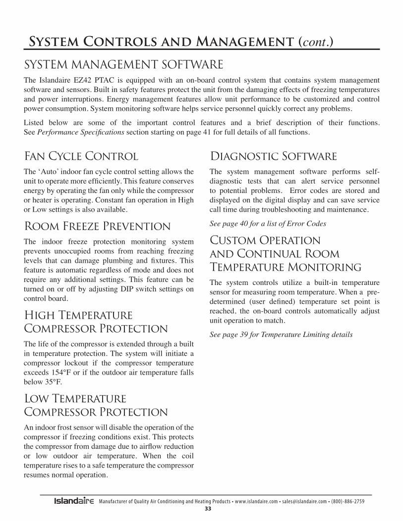
Fan Cycle ControlThe‘Auto’indoorfancyclecontrolsettingallowstheunittooperatemoreefficiently.Thisfeatureconservesenergybyoperatingthefanonlywhilethecompressororheaterisoperating.ConstantfanoperationinHighorLowsettingsisalsoavailable.
Room Freeze PreventionThe indoor freeze protection monitoring systemprevents unoccupied rooms from reaching freezinglevels that can damage plumbing and fixtures. Thisfeatureisautomaticregardlessofmodeanddoesnotrequire any additional settings. This feature can beturnedonoroffbyadjustingDIPswitchsettingsoncontrolboard.
High Temperature Compressor ProtectionThelifeofthecompressorisextendedthroughabuiltin temperatureprotection.The systemwill initiateacompressor lockout if the compressor temperatureexceeds154°Foriftheoutdoorairtemperaturefallsbelow35°F.
Low Temperature Compressor ProtectionAnindoorfrostsensorwilldisabletheoperationofthecompressoriffreezingconditionsexist.Thisprotectsthecompressorfromdamageduetoairflowreductionor low outdoor air temperature. When the coiltemperaturerisestoasafetemperaturethecompressorresumesnormaloperation.
Diagnostic SoftwareThe system management software performs self-diagnostic tests that can alert service personnelto potential problems. Error codes are stored anddisplayedonthedigitaldisplayandcansaveservicecalltimeduringtroubleshootingandmaintenance.
See page 40 for a list of Error Codes
Custom Operation and Continual Room Temperature MonitoringThe system controls utilize a built-in temperaturesensorformeasuringroomtemperature.Whenapre-determined (user defined) temperature set point isreached, the on-board controls automatically adjustunitoperationtomatch.
See page 39 for Temperature Limiting details
SYSTEM MANAGEMENT SOFTWAREThe Islandaire EZ42 PTAC is equipped with an on-board control system that contains systemmanagementsoftwareandsensors.Builtinsafetyfeaturesprotecttheunitfromthedamagingeffectsoffreezingtemperaturesand power interruptions. Energymanagement features allow unit performance to be customized and controlpowerconsumption.Systemmonitoringsoftwarehelpsservicepersonnelquicklycorrectanyproblems.
Listed below are some of the important control features and a brief description of their functions. See Performance Specifications sectionstartingonpage41forfulldetailsofallfunctions.
Manufacturer of Quality Air Conditioning and Heating Products • www.islandaire.com • [email protected] • (800)-886-275934
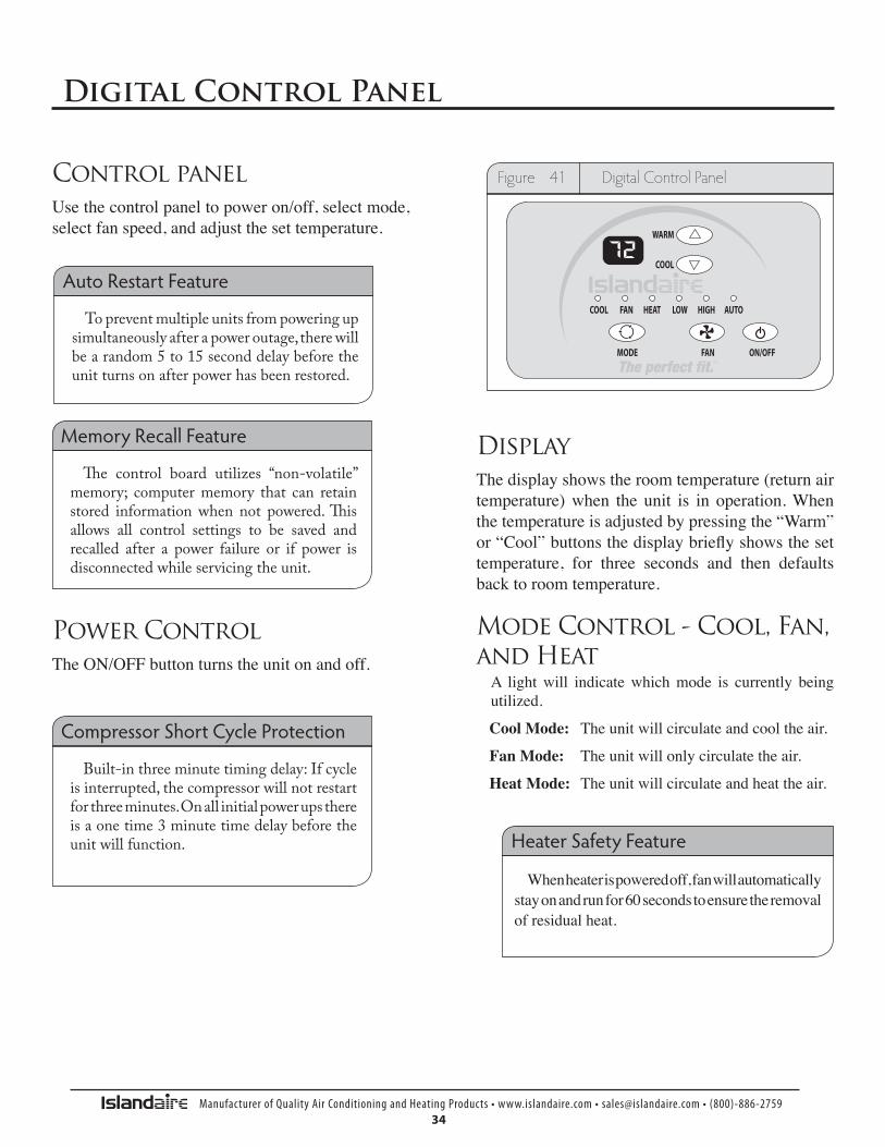
Control panelUsethecontrolpaneltopoweron/off,selectmode,selectfanspeed,andadjustthesettemperature.
Power ControlTheON/OFFbuttonturnstheunitonandoff.
DisplayThedisplayshowstheroomtemperature(returnairtemperature)when the unit is in operation.Whenthetemperatureisadjustedbypressingthe“Warm”or“Cool”buttonsthedisplaybrieflyshowsthesettemperature, for three seconds and then defaultsbacktoroomtemperature.
Digital Control Panel
Mode Control - Cool, Fan, and HeatA lightwill indicatewhichmode is currently beingutilized.
CoolMode: Theunitwillcirculateandcooltheair.
FanMode: Theunitwillonlycirculatetheair.
HeatMode: Theunitwillcirculateandheattheair.
To prevent multiple units from powering up simultaneously after a power outage, there will bearandom5to15seconddelaybeforetheunitturnsonafterpowerhasbeenrestored.
Auto Restart Feature
The control board utilizes “non-volatile”memory; computer memory that can retain stored informationwhen not powered.Thisallows all control settings to be saved andrecalled after a power failure or if power is disconnected while servicing the unit.
Memory Recall Feature
Built-inthreeminutetimingdelay:Ifcycleis interrupted, the compressor will not restart forthreeminutes.Onallinitialpowerupsthereisaonetime3minutetimedelaybeforetheunit will function.
Compressor Short Cycle Protection
Whenheaterispoweredoff,fanwillautomaticallystayonandrunfor60secondstoensuretheremovalofresidualheat.
Heater Safety Feature
AUTO
Figure 41 Digital Control Panel

Manufacturer of Quality Air Conditioning and Heating Products • www.islandaire.com • [email protected] • (800)-886-275935
Digital Control Panel
Fan Speed Control - Low, High, and AutoThe fan speed settings are adjusted with the Fanbutton.Eachtimethebuttonisdepresseditchangesthe setting between Low,High andAuto.A lightwillindicatewhichsettingiscurrentlybeingused.
IfeithertheLoworHighfansettingsareselectedthe fan will continuously operate in the selectedLoworHighspeedevenifthesettemperaturehasbeenreached.
When theAuto feature is selected, while the airconditioner is in the COOL or HEAT mode, thefan speeds will change between low and highautomatically as the temperature in the roomchanges and the fan will cycle off when the settemperatureisreached.
Temperature ControlsTheWarm and Cool buttons are used to raise orlower the set temperature. By depressing bothbuttons at once, the display will toggle betweenCelsiusandFahrenheit.
Operating Guidelines • Donotblockairflow.Efficientoperationofthe
unitdependsonfreecirculationofair.
Paper, leaves, and other debris can reduceefficiency and cause serious damage to thecompressor.
• Ensure that objects such as drapes, furniture,or plants are not blocking supply and returnairflow.
• DoNOToperateunitwithfrontpanelremovedorwithoutfilter,asthiswillvoidanywarranties.
• Keepdoorsandwindowsclosed.Leavingthemopenwillincreasetheworkloadontheunitandwillresultinhigheroperatingcostandexcessivecondensate.
• Do NOT operate unit during construction.Construction dust can clog filter and causepermanentdamagetoothercomponents.
Figure 42 Fan Controls - Digital Control Panel
AUTO
Figure 43 Temp Controls - Digital Control Panel
AUTO
Ifthetemperatureinavacantroomfallsbelow50°F(4.4°C)thefreezepreventionthermostatautomaticallystartstheheatingcycletopreventfreezingconditions.Allotheroperationswillbedisableduntilthetemperaturerisesabove58°F.Whenthetemperatureofthefreezeprevention
thermostat rises above 58°F the systemwillresumenormaloperations.
Freeze Protection Feature

Manufacturer of Quality Air Conditioning and Heating Products • www.islandaire.com • [email protected] • (800)-886-275936
Remote Wall Mounted Thermostats
TheEZ42canbecontrolledbyanyremoteelectronicthermostatthatcaninterfacewithRCBWYGterminals.A Wiring harness is provided with conductors forall applications (HeatCool,HeatPump,MultispeedFan, etc.) see details on the next page.TheControlSelectionjumpermustbeinT’STATposition.Duringacall,theremotethermostatwillpassRbacktothecontrolleronarespectiveterminal.Thepushbuttonson the touchpad become inactive in the remotethermostatmode.
Note: In terms of outputs, there are two types ofthermostats:RelayContactsandSolidState.
Manufacturersofsolidstateoutputthermostatsincludeloadingresistorsintheirinstallationkits.These(560Ohm 3W) resistors are meant to load thermostatsolidstateoutputs inorder for theoutputvoltage tobeeither0or24VAC,i.e.nofloatingvoltage.TheseresistorsareconnectedfromW,Y,Gtocommon(C),respectively
Youcanwire any typeof 24Vac thermostat straightinto the RemoteThermostat Interface on the PTACcontrolboard(seepage37).
Wireless Wall Thermostat
Wireless wall thermostats are designed to provideprecise temperature control without the installationlaborandexpenseofwiring.
•PoweredbyAAbatteries
•Mountsinanysuitablelocationthatwillprovideanaccurateroomtemperaturereading.
•Large LCD display provides the user withcurrent room temperature, set point temperature,time, program interval, and other system statusinformation.
RemoteControlNode
Used with a wireless wall thermostat, the RCNcommunicates with the thermostat using unlicensed900MHz,radiofrequencyenergy.
Energy Saving OptionsAutomatic Change-Over Remote MountedThermostatscanbeobtained toswitch fromheatingtocoolingandfromcoolingtoheatingautomatically.With automatic change over, the operation of theheating cycle or the cooling cycle is determined bythetemperaturerequirementofthespace.
Most thermostatswith this featureare set tochangeoverwhentheroomtemperaturevaries3-1/2°Ffromtheset-point.Theunitisplacedinthecoolingmodewhentheset-pointisover3-1/2°F;3-1/2oFundertheset point places the unit in the heating mode. This3-1/2°Fvariation is usually adjustable froma 1/2°Fdeadbandtoa5°Fdeadband.Eachcycleisrununtilthe set point temperature is reached, then that cycleisde-energized.Onsomethermostats, theautomaticchangeoverfunctioncanbeoverriddenmanuallybymovingthethermostatselectorswitchto“heat”orto“cool.”
The fan operation, with an automatic change overthermostat, is controlled by the fan selector switch.When placed in the “fan” mode, the fan runscontinuously.When placed in the “auto”mode, thefanwillonlyenergizewhen the thermostat calls forheatingorcooling.
Remote Thermostats
Remote Thermostat Control

Manufacturer of Quality Air Conditioning and Heating Products • www.islandaire.com • [email protected] • (800)-886-275937
Remote Thermostat Interface
Theremotethermostatinterfaceterminalblockislocatedonthepowermoduleboard. AWiringharnessisprovidedwithconductorsforallapplications(HeatCool,HeatPump,MultispeedFan,etc.)Itprovidesaconnectionforremotethermostatandenergymanagementinputs.
Toconverttothermostatoperation:1.Shutmainpowertounitoff2.Accessmaincontrolboardandturnremotethermostatdipswitchon3.Pluginthesuppliedthermostatharness.4.Connectwirestofieldsuppliedthermostat
Figure 44 Thermostat Terminal Block
R LSGH B Y W
GL C
TerminalR(Red)
Lowvoltageterminaltosupplyvoltagetoanexternalwallmountedthermostat.Thisterminaliscapableofsupplying100mAat18-30VACRMSovertheentireinputvoltagerangespecified.
TerminalLS(Purple)
When this lowvoltage terminal is connected to theR terminal, the compressor and electric heater aredisabled to provide an energy management systeminterface.
TerminalGH(Green)
WhenthislowvoltageterminalisconnectedtotheRterminal,andtheunitisinremotemode,theblower/fanwillberequestedforoperationonhighspeed.
TerminalB(Blue)
When this lowvoltage terminal is connected to theR terminal, and theunit is in the remotemode, thereversing valve is energized.Hydronic and electricheatshallbeattemptedasbackupsiftheBterminalisassertedandthecompressorislockedoutordisabled.Thisissubjecttotheconfiguredheatmodesavailable.
TerminalY(Yellow)
When this lowvoltage terminal is connected to theR terminal, and the unit is in remote mode, thecompressor will be switched on (the GL or GHterminalmustalsobeconnectedtotheRterminal).
TerminalW(White)
When this low voltage terminal is connected totheR terminal, and the unit is in the remotemode,first hydronic heat is attempted, and electric heat isswitchedonasbackup(theGLorGHterminalmustalsobeconnectedtotheRterminal).Thisissubjecttotheconfiguredheatmodesavailable.
TerminalGL(Orange)
WhenthislowvoltageterminalisconnectedtotheRterminal,andtheunitisinremotemode,theblower/fanwillberequestedforoperationonlowspeed.
TerminalC(Black)
Lowvoltage terminal,24VACcommon, toprovideoppositepolarityvoltagetowallthermostat.

Manufacturer of Quality Air Conditioning and Heating Products • www.islandaire.com • [email protected] • (800)-886-275938
A B C D
E
F
G
G
H
I
J
K
LMNOPQRT
V
BB
W
X
Z
AA
A TRANS – TRNSFRMR/ LOW VLT
B 24 VAC – ACCESSORY
C REMOTE THERMOSTAT
D EGND – ACCESSORY
E DIP SWITCH 1 REMOTE ON/OFF
WSHP ON/OFF
F DIP SWITCH 2 RESTART ON/OFF
FREEZE PROT ON/OFF
GAS HEAT ON/OFF
ELECTRIC HEAT ON/OFF
HEAT PUMP ON/OFF
G IR PLUG
H DISPLAY I ODA- OUTDOOR AIR SENSOR
J IDC – INDOOR COIL SENSOR
K RA – RETURN AIR SENSOR
L ODC – OUTDOOR COIL SENSOR
M NC – NORMALLY CLOSED
N NO – NORMALLY OPEN
O COND – CONDENSER MOTOR
P REV – REVERSING VALVE
Q GAS – GAS VALVE
R CNU – EVAPORATOR MOTOR
HI
LO
COM
S L2(N2)
T L2(N1)
U L2(N3)
V CNT – TRANS/LINE VOLTAGE
W FUSE
X L1
Y HYD/GAS – FAN SWITCH
Z NO2 – COMPRESSOR
AA COM2 – LINE 1
BB NO1 – ELECTRIC HEATER
CC COM1 – LINE 1
SU
Y
KEY Fuse
An easily replaceable6.3Amp250Vfuseisconveniently located oncontrolboard.
V
PRODUCED BY AN AUTODESK EDUCATIONAL PRODUCT
PRODUCED BY AN AUTODESK EDUCATIONAL PRODUCT
PRO
DU
CED
BY
AN A
UTO
DES
K ED
UC
ATIO
NAL
PR
OD
UC
T PRO
DU
CED
BY AN AU
TOD
ESK EDU
CATIO
NAL PR
OD
UC
T
1
1
2
2
3
3
4
4
A A
B B
C C
D D
SHEET 1 OF 1
DRAWN
CHECKED
QA
MFG
APPROVED
User 3/25/2010
DWG NO
TITLE
SIZE
CSCALE
REV
Figure 45 Control Board Physical Featrures
Control Board

Manufacturer of Quality Air Conditioning and Heating Products • www.islandaire.com • [email protected] • (800)-886-275939
DISPLAY CODE LOW LIMIT(DEGREES F)
HIGH LIMIT(DEGREES F)
R1 63 86
R2 65 86
R3 65 90
R4 67 88
R5 67 92
R6 69 90
R7 68 72
R8 (FACTORY DEFAULT) 60 90
Available Setpoint Ranges
Settingcustomizedtemperaturesetpointrangescansaveenergycostsbylimitingextremesettings.
ToentertheSetpointsetupmode,holddowntheFAN+WARMbuttonsfor5seconds.
Whiletheunitisinthismode,youcannowscrollthroughaseriesofcodes(R1,R2,R3,R4,etc.)toselectthedesiredtemperaturelimitingsetting.Tomovefromonecodetothenext,presstheFan+Warmbuttonstogethertomovetothenextcodeonthedigitaldisplay.Seechartatrightforthecodesandthesetpointrangetheyeachrepresent.
Toacceptthenewsetpoint,releasethebuttonsfor10secondswhenthedesiredcodeisdisplayed.ThechangewilltakeeffectwhentheON/OFFkeyispressedasecondtime,returningthedisplaytonormalfunction.
Tocancelthechange,wait10secondswithoutpressingtheON/OFFbuttonasecondtime.
HowtoSettheHeatingandCoolingLimitsSet Temperature Limiting
AUTO
RA
Figure 46 Display - Temp Limit Code
R1 Fan&
Warm
Temperature Limiting

Manufacturer of Quality Air Conditioning and Heating Products • www.islandaire.com • [email protected] • (800)-886-275940
Control Panel Display Diagnostics
Sensorsintheunitcontinuallymonitortheindoorcoil,outdoorcoil,andoutdoorairconditions.Ifabnormalconditionsaredetected,anerrorcodeisdisplayed,removingtheguessworkintroubleshootingaunit.
Diagnostic & Error Codes
ERROR CODE DIAGNOSIS CAUSE NOTE
E2RETURN AIR (RA)
TEMPERATURE SENSOR FAILURE
RA SENSOR BROKEN OR LOOSE AT BOARD CONNECTION TURN OFF POWER TO DISPLAY
E3INDOOR COIL (IDC)
TEMPERATURE SENSOR FAILURE
IDC SENSOR LOOSE OR BROKEN AT BOARD CONNECTION TURN OFF POWER TO DISPLAY
E4 ABNORMAL OPERATION • CHECK PROPER LOCATION OF IDC SENSOR AND ODC SENSOR • ENSURE THAT BOTH SENSORS ARE SECURE TO COILS • COMPRESSOR FAILURE • COMPRESSOR OVERLOAD OPEN • REFRIGERANT LEAK
TURN OFF POWER TO DISPLAY
E5OUTDOOR COIL (ODC)
TEMPERATURE SENSOR FAILURE
• ODC SENSOR BROKEN OR LOOSE AT BOARD CONNECTION TURN OFF POWER TO DISPLAY
E9 SYN. FAULT TERMINALS OPEN
• HIGH PRESSURE SWITCH OPEN - DIRTY CONDENSER COIL (COOLING) - FAILED CONDENSER MOTOR (COOLING) - BE SURE BAFFLES ARE INSTALLED (IF REQUIRED) - REFRIGERANT RESTRICTION - DIRTY FILTER / EVAPORATOR COIL (HEAT PUMP) - EVAPORATOR MOTOR FAILURE (HEAT PUMP) - RETURN / SUPPLY AIR RESTRICTED (HEAT PUMP) • ALL ADDITIONAL SAFETYS ADDED TO UNIT SHOULD BE CHECKED
TURN OFF POWER TO DISPLAY
*FOR BOARDS THAT DO NOT HAVE SYN. FAULT TERMINALS, CAUSES 1-7 LISTED UNDER E-9 WILL USE E4 ERROR CODE
AUTO
RA
Figure 47 Display - Error Code
E 2
Error Codes

Manufacturer of Quality Air Conditioning and Heating Products • www.islandaire.com • [email protected] • (800)-886-275941
Performance Specifications
PACKAGED TERMINAL COOLING UNIT WITH HEAT PUMP OR ELECTRIC HEATINGPARTII:SPECIFICATIONSSizeRange:Cooling:6,900to15,100BtuhHeating:6,000to14,100BtuhHeatPump6,400to17,000BtuhElectricIslandaireModelNumbers:PARTII:GENERAL1.01 SYSTEM DESCRIPTION Singlepiece,thru-the-wallelectricallycontrolled
unitusinghermeticrotarycompressorforcoolingandheatpumporelectricresistanceheat.
A.InsulatedWallSleeve: Shallbeentirelyconstructedofgalvanized,
heavy-gaugesteelwithanAntiqueIvorypowderpaintcorrosionresistantfinish.Wallsleevesshallbeinstalledthroughthewallasshownonplansandshallhavefactoryprovisionsforuseofappropriatefasteningdevicestosecuresleevetothewall.Innoeventshallfastenersbeinstalledthroughthebasepaninthebottomofthewallsleeve.
Wallsleeveshallprovideexcellentthermalinsulation,willhavesuperioroutdoornoiseabsorptionandshallbecorrosionfreeforthelifeoftheproduct.
Wallsleevemusthavedimensionsof42in.widthx16in.heightx147/8in.depthandbeshippedwitharearweatherbarrierinstalled.
B.OutdoorLouveredGrille: Shallbe(stamped)(architectural)anodized
aluminumasshownonplans.Louvershallbe
(finishednatural)(painted)asshownontheschedule.Louversshallbeeasilyinstalledfromtheinsideofthebuildingafterthecabinet/wallsleevehasbeeninstalled.SpecialfieldfabricatedlouversmustbeapprovedbythePTACmanufacturerastofreeareaandaircirculationrequirements.
Outdoorgrilleshallresistcorrosion,breakageandmatchthecolorspecifiedondrawingscheduleandspecifications.
C.Subbase: Subbasewillsupportthewallsleevewhen
itextendsintotheroommorethan4inches.Subbasemustcomefromthefactorypre-assembled,withabuiltinreceptacle(sizeasspecifiedondrawingscheduleandspecifications)orwithfactoryinstalledhardwire,pre-sizedforanexactfittotheunit.
1.02 QUALITY ASSURANCE SystemshallbeapprovedandcertifiedbyETL.
ChassiscapacityandefficiencyperformanceshallbecertifiedinaccordancewithARIstandard310/380.ChassisshallmeetASHRAEStandard90.1forminimumenergyefficiency.
1.03 DELIVERY, STORAGE, AND HANDLINGA.Thepackagingofthechassisshallbesufficient
toprotectthechassisfromdamageduringshipmentviaanenclosedtruck.
B.Chassis,wallsleeves,andgrillesshallbeshippedinseparatecartons.Universalhandlinginstructionsshallbedefinedandvisibleonthecarton,fromfront,backandsides.
C.Unitshallbestoredandhandledpermanufacturer’srecommendations.

Manufacturer of Quality Air Conditioning and Heating Products • www.islandaire.com • [email protected] • (800)-886-275942
A.General: Factory-assembled,single-pieceheatingand/or
coolingunit.Containedwithintheunitenclosureshallbecompressor,coils,fansandfanmotor,heatingmeans,controls,allwiringandpiping,andafullrefrigerantcharge(R-410A).
B.Chassis: Thechassisshallbeafactory-assembled,single
pieceheatingand/orcoolingunit,thatissimpletoinstallandoperate.Justslidethechassisintoawallsleeve,plugitintoanoutlet,andoperateafterinstallation.Thechassisdimensionsshallnotexceed42in.wideand16in.highwithroomcabinetinplace.Thechassisshallconsistofthefollowingfunctionalsectionsandcomponents:1.OperatingCharacteristics: Chassisshallbecapableofstartingandrunningat115°FambientoutdoortemperaturepermaximumloadcriteriaofARIStandard310/380.
2.Electrical: Chassisshallbeequippedwitha58in.powercord.ThechassiscurrentdrawshallbespecifiedonthechassisnameplateandmatchelectricalrequirementsspecifiedontheContractdrawingscheduleandspecifications.ThepowercordplugconfigurationshallconformtoNEMAstandardsandtheratingshallsupportthecurrentdrawoftheelectricresistanceheater.
For265Vinstallations,ULcodesrequiretheuseofanelectricalequippedsubbaseforpowercordusageorhardwireconduitfornon-cordedinstallations.
C.AirflowSystem: Theairflowsystemshallconsistofone
permanentsplit-capacitor,direct-drivepermanentlylubricated,two-speedfanmotorfortheindoorandoutdoorfans.Theoutdoorfanshallbeadynamicallybalanced,corrosionresistantpolymermulti-bladeaxialflowdesign,withintegratedslingerring.Theindoorfanshallbeadynamicallybalanced,polymer,reversecurveblowerwheel,toassureuniformairdistribution.TheFanMotorshallbeofanencloseddesigntoreducetheeffectsofmoistureandcorrosion.
D.CompressorandRefrigerant: Therotary-typeCompressorshallbefully
hermeticwithinternalandexternalvibrationisolation.Therefrigerationsystemwillbesealedandcontainafullrefrigerantcharge(R-410a).
E.Coils: Condenserandevaporatorcoilstobe
constructedofhigh-efficiency,lancedsinewaveenhancedaluminumfinsandseamlessaxialgroovedcoppertubing,necessarytoachieveEERandCOPrating,asspecifiedonthechassisnameplate.
F.Factory-InstalledElectricHeater: Thefactory-installed,opencoiltype,electric
heaterisstandardinheat/coolandheatpumpchassis.Theelectricheatershallcontainbothanautomaticresetandaone-shotovertemperatureprotectiondevice.
TheheatingcapacityoftheelectricheatershallbeasidentifiedontheContractdrawingscheduleandinthespecifications.
Performance Specifications (cont.)
2.01 EQUIPMENT

Manufacturer of Quality Air Conditioning and Heating Products • www.islandaire.com • [email protected] • (800)-886-275943
Performance Specifications (cont.)
G.FrontPanel(suppliedwithchassis): Frontpanelshallbeconstructedofapolymer
materialtoresistbreakageandcorrosion.Itshallhaveafrontlouveredsurfacewithintegratedairfilters.Theairfiltersshallbeeasilyaccessiblewithoutremovingthefrontpanelfromthechassis.
H.FreshAirVent Thechassisshallhaveamanualadjustablefresh
airventwithaconcealedmanualcontrol.Theventcontrolshallallowamaximumof50cfmoffreshairtobedrawnintotheroomwhentheindoorfanisoperatingandthedoorisopen.
I.CondensateRemovalSystem Thechassisshallhaveacondensateremoval
systemconsistingofacondensatesuctionport,todrawandatomizecondensate,andaslingerringintegratedintheoutdoorfan,todispersecondensateontothecondensercoiltobeevaporated.
CondensationaccumulatedduringreversecycleheatingmustNOTbeevaporatedagainsttheindoorcoilsoastopreventcontaminationoftheindoorairwithpollutantsandodors.Condensationmustbedisposedofusinga(external)(internal)drainsystemasshownonplans.
3.01 CONTROLSAllstandardmodelsshallbeequippedwithelectromechanicalcontrolstosimplifytheserviceabilityoftheunit.A.StandardControls Thechassisshallhavestandardcontrols,
accessible.ThemodeselectioncontrolshallprovideOFF,FANONLY,HEATorCOOLoperations.
Thetemperatureselectioncontrolshallbeanadjustablethermostatwithupperandlowerlimits.
B.ContinuousFan Allstandardmodelsshallhaveacontinuous/fan
cycleselectorswitchlocatedbehindthefrontpanel.Itshallallowtheselectionofcontinuousfanoperationformaximumcomfortorcycleoperation(fanonlyrunswithcoolingorheatingoperation)formaximumenergysavings.
C.TemperatureLimiting AllstandardmodelsshallhaveTemperature
Limitingmanagementbuiltintothesystemcontrols.
Thetemperaturelimitingcontrolsallowaroomtemperaturesetpointrangetobeestablished,toavoidextremetemperaturesettings,tomaximizeenergysavings.
D.EmergencyHeat EmergencyHeatSwitch(HeatPumpModels
Only),uponfailureofthecompressor,shallautomaticallydisablethecompressorinheatingmodeandonlyallowtheuseofelectricstripheaterduringheatingcycles.TheEmergencyHeatswitchisactiveatalloutdoorambienttemperatures.
E.Thermostat Wallthermostatchassisshallcomefromthe
factoryreadyforwallthermostatinstallation,includingablankoutplateinplaceofthedigitalcontrolpanel.InstallationofharnessandDIPswitchrequired.
F.FanSpeedControl Wallthermostatchassis(RCandRPmodels)
shallhaveauserselectablefanspeedcontrolswitch,onthecontrolpanel,tooptimizefanspeedformaximumcomfort.
G.ProtectionCircuits: Compressorshallhaveautomaticreset,over
temperatureandovercurrentprotection.Thefanmotorshallhaveaninherent,automaticresetovertemperatureprotection.Theelectricheatershallhavetwoovertemperatureprotectors.

Manufacturer of Quality Air Conditioning and Heating Products • www.islandaire.com • [email protected] • (800)-886-275944
Heat pump units shall have the selected roomtemperaturemaintained by cycling either in the heatpumpmodeorelectricstripheat.Aheatpumpunitwithelectricheatisswitchedfromtheheatpumpmodetoelectricstripheatwhentheoutdoorcoiltemperatureis20°Forwhentheheatpumpcannotkeepupwiththeheatingloadandatwostagethermostatisused.
For heat pump operation, a room thermostat with aB** (heating changeover) terminal is required. Thiswill mean that some “auto changeover” thermostatscannot be used, asmany of them either do not havea B** terminal, or else energize the B** terminalcontinuouslywheninthe“auto”position.4.0.2ElectricHeatOverride
For heat pump applications, electric heat comes ononlywhentheoutdoorcoiltemperatureisbelow28°F,maximizingtheamountoftimetheunitoperatesinthemoreefficientheatpumpmode.TheminimumCOPforheat pumps, at 47°FDBoutdoor,must be2.9 for allsizes.
(Heatpumpmodelsshallalsoincludereversingvalve).4.0.3ReverseCycleAHeatPumpWITHback-upelectricheat– Thereversingvalve,thecompressor,theoutdoor
condenserfanmotorandtheindoorfanmotorshallbeenergized.Reversecycleheatingshalloccurwhentheoutdoorcoiltemperatureis28°Fandabove.Ifoutdoorcoiltemperaturedropsbe-low28°FortheOutdoorairtemperaturedropsto35°Forless,Electricheatistheonlysourceofheat.WhentheOutdoorcoiltemperatureraisesbackto40°Fandabove,thentheCompressororElectricheaterisused.
Atemperature-sensingdeviceshallbeusedtomonitortheoutdoorcoiltemperaturetolimitfrostbuildup.Defrostingoftheoutdoorcoilwillbeactivatedwhenoutdoorcoiltemperaturedropsbelow28°Foroutdoorairtemperaturedropsto35°Forless.Defrostingisterminatedwhenoutdoorcoiltemperaturerisesbackto
40°F.Duringdefrosting,bothcompressorandtheoutdoorfanareturnedoff.Theindoorfanwillrunatitssetspeed.
CondensationaccumulatedduringreversecycleheatingmustNOTbeevaporatedagainsttheindoorcoilsoastopreventcontaminationoftheindoorairwithpollutantsandodors.Con-densationmustbedisposedofusinga(external)(internal)drainsystemasshownonplans.
B.HeatPumpWITHOUTback-upelectricheat– Thereversingvalve,thecompressor,theoutdoor
condenserfanmotorandtheindoorfanmotorshallbeenergized.Reversecycleheatingshalloccurwhentheoutdoortemperaturesare35°Fandabove.
Ifoutdoorcoiltemperaturedropsbelow28°FortheOutdoorairtemperaturedropsto35°Forless,thecompressorstopsandthereisnosourceofheat.WhentheOutdoorcoiltemperatureraisesbackto40°Fandabove,thenthecompres-sorreversecycleistheheatsource.
Atemperature-sensingdeviceshallbeusedtomonitortheoutdoorcoiltemperaturetolimitfrostbuildup.Defrostingoftheoutdoorcoilwillbeactivatedwhenoutdoorcoiltemperaturedropsbelow28°Fofoutdoorairtemperaturedropsto35°Forless.Defrostingisterminatedwhenoutdoorcoiltemperaturerisesbackto40°F.Duringdefrosting,bothcompressorandtheoutdoorfanareturnedoff.
Theindoorfanwillstopifindoorcoiltempera-turefallsbelow78°F.Itwillrestartatitssetspeedwhenindoorcoiltemperaturerisesbackto80°F.
Performance Specifications (cont.)
4.0.1 HEAT PUMP OPERATION

Manufacturer of Quality Air Conditioning and Heating Products • www.islandaire.com • [email protected] • (800)-886-275945
4.01ACCESSORIES:A.MetalWallSleeveshallbeaone-piece,extended
wallsleeve,withfactoryinstalledinsulation.B.Architecturallouvershallbepaintedaluminum
forasuperiorcolormatchtothebuilding.C.Subbaseshallbepre-assembledfromthefactory
andULlisted. Subbaseoptionsinclude:
1.Non-electricalsubbase:Thenon-electricalsubbaseshallbepre-assembledandprovidesmechanicalsupportandrequiresnowiring.
2.Electricalsubbase:Theelectricalsubbaseshallbepre-assembledwithfactory-installedelectricaljunctionboxcontainingareceptacleforcordedunits.
3.Hardwiredsubbase:Thehardwiredelectricalsubbaseshallbepre-assembledwithfactoryinstalledelectricaljunctionboxcontaining19in.offlexibleconduit(foraperfectfittotheunit)andallmatingconnections.
D.Hardwirekitshallprovideapermanentconnectiontotheunit.
Thehardwirekitmountsonthefrontrightsideoftheunitandshallhave36in.offlexiblesteelconduitandaconnectorforeasyconnect/disconnect.
E.CondensateDrain Thisuniversaldrainkitshallbeusedinternally
orexternallytorouteexcesscondensatetoadrainagesystem.Itcanbefield-installedonanyIslandairewallsleeve.Thedrainkitshallbeattachedtotheexteriorrightorleftsideoftheallsleeveforexternaldrainingormaybemountedtothebottomofthewallsleeveforinternaldraining.
F. LateralDuct: Thekitshallincludeanadapterplenum,
extensionduct,wallregisterandwallmolding.Thelateralductsystemallowsonesystemtoheatorcooltwoadjacentrooms,bydirectingupto30%oftheairflowtotheadjacentroom.Seesection4.0fordetailedspecification.
G.FrontDeskControl: Unitcontrolsshallprovidefrontdeskcontrol
onallunits,allowingindividualunitstobeturnedonandofffromaremotelocationorbyamotionsensingdevice.Frontdeskcontrolsshallinterfacetomostenergymanagementsystems.
H.Securitydoor Thekey-lockingsecuritydoorkitshallprevent
unauthorizedaccesstotheunit’sheatingandcoolingcontrolsandpreventstamperingwithunitsinpubliclocationsandinstitutions.ThesecuritydoorshallincludetwomatchingkeysandkeysshallbecommontoallIslandaireSecurityDoorkits.
Performance Specifications (cont.)

Manufacturer of Quality Air Conditioning and Heating Products • www.islandaire.com • [email protected] • (800)-886-275946
LIMITED ONE YEAR PARTS AND LABOR PLUS ADDITIONAL 2ND THROUGH 5TH YEAR SEALED SYSTEM PART ONLY WARRANTY COVERING
ISLANDAIRE THRU-WALL AIR CONDITIONERS & HEAT PUMPS
THISWARRANTYAPPLIESTOTHEAIRCONDITIONERUNIT(“THEUNIT”)THATISTHESUBJECTOF THIS SALE AND IS IN LIEU OF ALL OTHER WARRANTIES EXPRESSED OR IMPLIED. THIS WARRANTY DOES NOT APPLY TO ANY ACCESSORY THAT IS NOT A PART OF THE UNIT AS SHIPPED BY ISLANDAIRE THIS WARRANTY APPLIES ONLY TO THE ORIGINAL EQUIPMENT AT THE ORIGINAL INSTALLATION LOCATION. PROOF OF PROPER, ROUTINE MAINTENANCE WILL BE REQUIRED IN ORDER TO MAINTAIN EXTENDED WARRANTY.
ISLANDAIREthe“Company”ofEastSetauket,NewYorkwarrantsthattheunitisfreefromdefectsinmaterialandworkmanshipundernormaluseandservice,forthetwelve-monthperiodfollowingthedateofinstallation*.
WARRANTYCoverageincludesrepairorreplacement,attheCompany’soption,ofanydefectivepartsthatfailundernormaluseforthefirst365daysafterthedateofequipmentinstallation*undertheterms,conditionsandlimitationsofthewarranty.AlldefectivepartsshallbereturnedwithinthirtydaysafterremovaltotheCompanyatsuchlocationsastheCompanymaydesignate.Islandairereservestherighttoimposeaninspectionchargeand/orarestockingfeeincaseswherepartsorequipmenthavebeenimproperlyreturnedasdefectiveand/orasbeinginwarranty.Awarrantypartcanonlybereplacedonetimeoverthedurationofthewarrantyperiod.
WARRANTYcoveragealsoincludesLaborChargesonallcoveredrepairsperformedbyaIslandaireAuthorizedServiceCompanyinaccordancewiththeterms,conditionsandlimitationsofthewarranty.Extrachargessuchasemergencycalls,nuisancecalls,mileage,overtimeorshippingarenotcovered.Check,test,andstartbyanexperiencedpersonaretheresponsibilityoftheinstallingcontractor.Check,testandstartshallincludephysicallyoperatingeachunitinbothcoolingandheatingmodesandcorrectinganyminordeficienciesnoted.Onoccasion,wiresmaybecomedisconnectedorcomponentsmaybedislodgedfromtheirbasesasaresultofroughhandlingduringtransport,causingimproperfunctioningoftheunit.CorrectionoftheseminorconditionsispartofCheck,Test,andStart.
ADDITIONAL SEALED SYSTEMWARRANTY Coverage includes replacement of any part of the sealedrefrigerationsystem,includingthecompressor,evaporator,condenserandconnectingtubing,thatprovestobedefectivefromthe2NDthrough5thYearfromdateofinstallation.Laborisnotincluded.FreightchargesforreplacementandreturnofdefectivewarrantypartswillbetheCompany’sresponsibility.
INNOEVENTSHALLTHECOMPANY’SMAXIMUMLIABILITYEXCEEDTHESELLINGPRICEOFTHE UNIT CLAIMED TO BE DEFECTIVE
AsaconditionprecedenttotheCompany’sobligationunderthisWARRANTY,itshallbetheobligationoftheOwnerduringthedesignatedWARRANTYperiodtofurnishthefollowinginformationtotheCompanywithinthree days after unit failure: 1)ModelNumber and SerialNumber of unit involved, 2)A full and completedescription of the problem encounteredwith the unit.Upon receipt of the above information, theCompanywillreplytotheOwnerwithinaperiodnottoexceedfifteenworkingdays,withadescriptionoftheactiontheCompanydesirestotake.
ContacttheIslandaireCustomerServiceDepartmentatU.S.800-886-2759
TovalidatethisWARRANTY,youmustcompletetheregistrationinformationbelowandreturnthepre-addressedcardtoIslandairewithinsevendaysofequipmentinstallation.TheactualwarrantytypeforyourequipmentisstatedontheoriginalIslandaire invoice forsaidequipment.Proofof installationdate isrequired.*PleasebeadvisedwherenoWarrantyRegistrationCardhasbeenreturned,theoriginaldateofinvoiceoftheequipmentshallbecomethestartdateofthewarrantyperiod.
Typical Warranty - EZ42
22 Research Way, East Setauket, NY 11733 • 1-800-886-2759e-mail: [email protected] • www.islandaire.com
Ph: 631-471-2900 • FX: 631-471-2913

Manufacturer of Quality Air Conditioning and Heating Products • www.islandaire.com • [email protected] • (800)-886-275947
M A N U F A C T U R E R O F Q U A L I T Y A I R C O N D I T I O N I N G A N D H E A T I N G P R O D U C T S
22 Research Way, East Setauket, NY 11733 • 1-800-886-2759e-mail: [email protected] • www.islandaire.com
Ph: 631-471-2900 • FX: 631-471-2913
Locally Represented By: