engineering lehigh university bethlehem, pennsylvania
TRANSCRIPT

,,.
fRITZ ENGINEERiNG LABORATORYLEHIGH UNIVERSITY
BETHLEHEM, PENNSYLVANIA
EFFECT OF RIGID BEAM-cOLUMN COlrNECTIONSON COLUMN STRESSES
by Inge Lyse· and E. H~ MountO- - - - - ~ ~ - - - - - - - - ~
INTRODUCTION
A study of the design and behavior of the top angle
beam connection designed for end restraint appeared in the
October 19;56 and October 1937 issues of THE WELDING JOURNAL'.
The present paper contains the results of a study of the lo~
cali zed column stresses produced by this type of connection.
The investigation was sponsored by the Structural Steel Weld
ing Committee of the American Welding Society and was carried
out at the Fritz Engineering Laboratory of Lehigh University.
'!'he column moments induced by partial rigid!ty in the
beam connection may be detertnined by modification of .anyone
of a number of methods ot rigid trame analysis. This investi
gation was, therefore, confined to a stUdy of those localized
column stresses of a secondary nature. The object of the in
vestigation was to determine whether these secondary stresses
acting simultaneously with axial column loads were of suf'fi
cient magnitude to cause local buckling of the column when
subjected to. vertical loading.
- - - - - - - - - -- - ~ ~ - - - ~ ~ - - - - - .- ~ - -.-* Researeh Prof'essor of Englneel'lng Materials
Lehigh University, Bethlehem, Pennsylvania
o American Welding Society Research Fellow .Lehigh University, Beth18hem, Pennsylvaniain immediate eharg~ of investigation
, PROGRESS REPORT ON WELDED BEAM-cOLUMN CONNECTIONS /by Inge Lyse and G. J. Gibson
EF:F'ECT OF WELDED TOP ANGLES ON BEAM-GOLUMN CONNECTIONS Vby Inge Lyse and G. J. Gibson

- 2
A series of beam-column connections with column size,
beam size and top-angle' size as variables were investigated.
Analysis of the data obtai~ed indicates that these localized
stresses are of a negligible order within the proposed limits
of the top angle connectio~.
ACKNOWLEDGMENT
The investigation was carried out under the direction
of the Structural Steel Welding Committee of which Mr. L. S.
Moissei!!' is Chairman and Mr. W. Spraragen the Secretary.
Acknowledgment is due all members of the Committee for their
interest in the work and their assistance in for.mulatlon of
the test program. Acknowledgment is also due Mr. Roger Fluck
of the Bethlehem Steel Company for welding of specimens and
Mr. H. J. Godfrey and other members of the Fritz Engine~rlng
Laboratory staff for their assistance in carrying out this
investigation.
TEST PROGRAM
The original program provided that the principal test
ing be carried out using a simplified specimen consisting of a
plate simulating the tension flange of a beam, welded to the
column flange. Direct tension was applied to the plate which
in turn transferred the tension to the column flange and web.
Pilot tests, however; indicated that this type of specimen
could not be made to duplicate column flange stresses produced

- :5
by the welded top angle connection. The program was, there
fore, revised and a cantilever specimen of the type shown in
Fig. 1 was substituted. The program in ita-final form pro
vided for the testing of fourteen specimen~ of this general
type with beam size, column size, and top angle size varying
as indicated in Table I.
FABRICATION OF TEST SPECIMENS
The stub columns were cut to size and mounted hori
zontally on a jig. The seat angle was then welded,in place.
The beam was set in place and shimmed to allow 1/8 to 1/4-1n.
clea.rance between beam. end and column face. The beem was
tack-welded to the $eat angle and the shims removed. The
top angle was tack-welded in place and the beam. checked .fin
ally for perpendicularity to column face. The top angle
welds were c9mpleted and the jig rotated through 90° to allow
placing of the final seat angle welds in the horizontal posi
tion. The specimen was then reversed in the jig and the pro
cedure repeated in attaching the second beam to the opposite
column face. Top angle welds were placed in two ways. The
weld metal was plaeedin a se~ies of beads until the desired
weld size was reached" or the jig was rotated through. 45° and
the weld metal floated in by a series of flat horizontal beads.
No appreciable difference in behavior between welds :made by
these two methods was noted in testing and, therefore, no dif
ferentiation is made in the test data between specimens welded
by the two methods.

- 4
All welds were made by a qualified welder and upon
failure showed excellent fusion and absence of inclusions
or blow holes. All large welds were made with 3/l6-in.
Murex heavy mineral coated electrode and all tack-welds and
small finishing beads were made with 5/32-1n. Airco No. 87
coated electrode.
METHOD OF TESTING
All specimens were tested to failure in a 300,000
lb. Olsen testing,machine. Loading was applied as shown in
Fig. 1. The beams were supported on rollers placed 32 in.
from the column faces and the load applied to the center of"
the column through a spherical bearing block.
The rotation of each beam at the face of the column
was measured· bY' means of :four Ames dials reading to 1/1000
in. attached to the beams with plungers bearing against the
column .face as shown in Fig. 1. Gage plates were tack-welded
on the centerline of the column web opposite both seat and
top angles. Three rows o.f gage holes were spaced at vapying
distances from the column web. Corresponding gage holes on
the imler surface of the column flange permitted measurement
of column flange deflections relative to the column center
line. Gage holes were spaced .at 2-1.n. intervalts in the rows
and permitted observation of deflections four inches abov.
and below the weld connscting top angle to eolumn and two
inches above and below the heel of the seat angle. .An Ames
dial reading to l/lOOO..,.n. and modified as shown in Fig. 2

- 5
was used in measuring the flange deflections.
The specimens were whit~vrashed before testing and
observation of scaling aided in determining the location
of critical points.
TEST DATA
General information concerning specimen 'size, design
loads, ultimate strength, apparent factors of safety and
flange deflections is presented in Table I. The factors ot
safety listed in Table I are factors of safety against end
failure. It should be remembered that the flexibility of
this type of connection is such that failure by oV6%"stressing
at the center ot the beam will occur prior te ultimate tall
ure of the connection. The tabulated flange de:f1ect:tons are
those observed at the :flange edge at the point ot attachment
of the top angle and at the heel of the seat angle. Deflect
ions of slightly greater magnitude than those recorded at the
top'angle were observed at a point on the flange edge two
inches below the point ot attachment of the top angle. This
phenomenon was the result of the moment applied to the colUlm1
flange by the top angle and di sappeared as loads were increased.
above the design load, so that the maximum deflections occurred, .at the point of attachment of the top angle. The shift in the
point of maximum deflection may be accounted for by the fact,. .that yielding of the top angle weld at or slightly above design
load allows the moment applied to the flange to increase at a

6
much lower rate, while the direct pUll continues to increase
With the increased load.
Flange deflections observed for angles smaller than
;3 by :3 by l!2-1n. and having a length less than 8 in. were
very small and erratic.lI!
Typical transverse flange deflection curves for larger
angles are shown in Fig. 3 and 4. In each case the le.ft halt
of the figure shows the observed deflections at the point of
attachment of the top angle and the right haa. of' the figure
shows corresponding curves tor a point two inches below the
top angle connection. Typical deflection curves of the flange
edge are presented in Fig. 5. These curves show the local na
ture o£ the deflections. In all cases the piotted deflections
are the average of observed deflections for corresponding
points on opposite sides of the column web. The average was
used in order to eliminate the effect of any.eccentricity in
the loading of the specimen.
Flange deflections at the seat angle were at all tLmes
small and erratic. The general trend, however, seemed to be
in the direction of uniform deflection tor all points on a
transverse section which indicates that the major portion of
the deflection was the result of elastic and plastic deforma
tion of the web.
The measured end rotations ot the beams were used in
calculating heel deflections of the t.op angles and in the

- 7
determ.1nation of the rigidity of' the connection. A typical
load-deflection curve is shown in Fig. 6. The results were
plotted f'or .three angles of' the same size. :3 by :3 by l/2-in.
but with varying lengths of 6, 8, and 10 in. The f'act that
the pointsf'all so closely together indicates that variation
in length has no effect upon the f'lexibility of the eonnect
ion. However, incrlase in the length of the angle over six
inches showed a tendency to deerease the efficiency of the
connection, i.e., decrease the ultimate load expressed in
pounds per inch length of top angle. This tendency became
particularly pronounced in angles as large as :3 by :3 by 7/8
:tn. and 3 by :3 by 1 in. Fig. 7 shows the type ot failure
which occurred in a :3 by :3 by 1 In. top angle 10 in. in length.
This failure is typical. of angles of this size. Failure start
ed by tearing of the ~eld at the root in the center of the
column flange and progressed toward the throat and in both
directions from the center to the ends of the welds.
Elastic and plastic deformations of the web contribute
materially to the center deflections of the flange as shown in
Fig. :3 and 4. The critical points are shown by the scaling of
the whitewash in Fig. 8. The scaling at the top angle is in
clined at 45° indicating that the principal force acting is
directtenslon applied at the point of attachment ot the top
angle to column flange and acting in a direction perpendicular
to the column flange. The scaling at the s,eat angle is typic"
al of web crippling due to bearing loads.

.... 8
DIsaUSSI ON AND ANALYSIS OF TEST RESULrrs
Before any attempt was made to analyze the column
stresses it was necessary to establiah an upper limit of top. ..
angle size which in turn esta.blished the maximum load which,
need be considered in the analysis of eolunm stresses and de.
flections.
The rigidity of the cantilever connection wa.s computed
as shown in Fig. 9. The eantilever was assumed to be an end
portion of a partially restrained beam having an identical
connection at the opposite end, the point of inflection being
coineident with the point of application of load to the canti
levered beam. The load, end rotations and point of'inflection
being fixed by test procedure and results, it wa~ possible to
calculate the length of this imaginary beam. and to compare its
free end rotation with the observed rotation of the cantilevera
This comparison gave a measure of the rigidity developed by the
connection under various load conditions. Fig. 10 presents a '
comparison of rigidities developed by three sizes of' angle,
namely; 3 by 3 by 1/2: in.• ; :3 by 3 by 5/8 in., and :3 by 3 by
3/4 in. The length of these angles was also a variable but
Fig. 6 showed that the length has no eff'ect upon -the flexi
bility or its reciprocal, rigidity. In calCUlating the rigid
ity or the connection it was necessary to use a beam size which
when coupled with the connection in question gave a balanced
design. Since Table I shows that beam size ha.s no erfect upon

- 9
the action of the top angle it was necessary to consider the
..balanced design only in computation of the rigidity. The
dotted curve in Fig. 10 intersects the rigidity curves at
the per cent fixity developed at design load. These curves
are typical of othera plotted for the remainder of the spe
cimens. They show that in all cases the rigidity de,veloped
at design load is well above the mlnim'U.D!l allowab~e rigidity
of' :fifty p~r cent. They also ahow that design load rigidity
tends to increase with angle size rather rapidly :for those
sizes eq~a1 to ,or greater than 3 by 3 by 3/4 in. This in
crease in rigidity im caused by two factors. First~ genera.l
yielding throughout the entire weld is improbable in the
larger size welds. Second, the ductility of the top angle
transverse to ,the direction or rolling was found by free bend
tests to decrease rather markedly in angle ,sizes aboue 3 by 3
by 3/4 in. As the flexibility of the connection depends upon
the yielding ot the top angle weld and the ductility of the
angle itself, these two factors tend to increase the rigidity
as mentioned abev'e. This inerea.se in, ri.gldity of the connect
ion is accompanied by a comparable decrease in the factor of
safety against end failure. The flexibili ty ~f' the connection
might be increased by increasing the length of leg of the top
angle but this in turn decreases the allowable load on the con
nection. Theref'ore an increase in the amount of' material used
in the connection at this point 1s not accompanied by a corres
ponding increase in load-eartiying abiJ,1ty.

- 10
The drop in efficiency of the connection accompanying
the use of lengths over six inches in the larger angles is
explained by consideration of the type of failure pictured in
Fig. 7. It is evident that at loads near the ultimate all
portions of the top angle weld are not contributing full value
at the same time. This condition can occur only in extreme
cases and is eliminated entirely it an upper limit to top
angle size be set at a point such that the largest beam used
in a balanced design wo~ld require a"top angle of length not
in excess of six inches. The above considerations led to the
establishment of an upp~r limit to top angle size of 3 by 3
by 7/8 in.
Examination of the transverse deflection curves of
Fig. 3 and 4 reveals the fact that the deflections may be
separated into two parts, that due to bending of the flange
and that due to yielding of the web. Such a division can be
only approximate as no actual measurements of web de:forma
tions were made.
Consideration of that portion of the deflection due.
to bending of the flange revealed that the transverse deflec
tion curves were very similar to the.dei'lection curves of a
simple cantilever uniformly loaded. A method of analysis
proposed in an article by Gregor, appearing in DER PRAKTISCHE
STAHLHOCHBAU, Band IV, 1932, and reviewed in LA SOUDRE A L' ARC
ELECTRIQUE, was used with certain modifications. A portion of
- 11
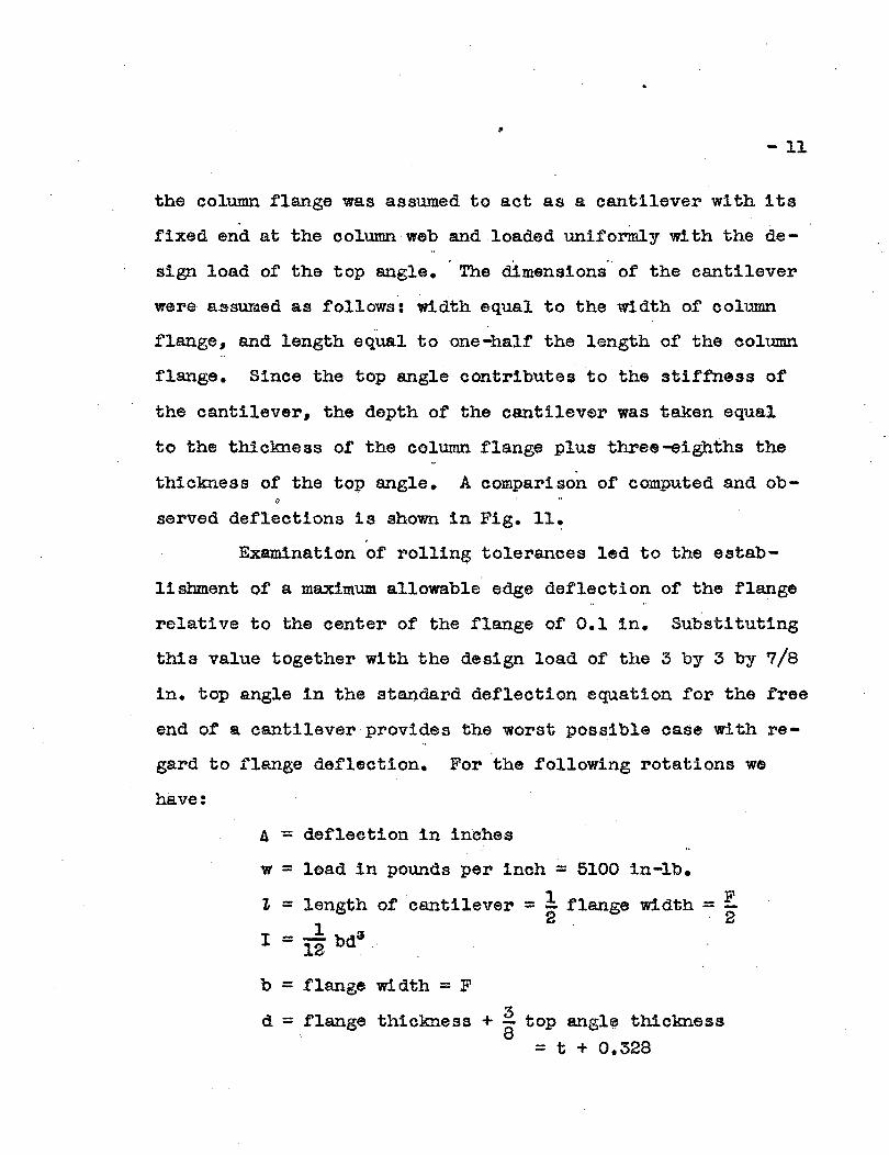
the column flange was assumed to act as a. cantilever wi th its~
fixed end at the column web and loaded uniformly with the de-
sign load of the top angle. The dimensions' of the cantilever
were assumed as follows: width equal to the width of' column..
flange, and length equal toone-half the length of the column
flange. Since the top angle contributes to the stiffness of
the cantilever, the depth of the cantilever was taken equal
to the thickness of the column flange plus three-eighths the
thickness of the top angle. A comparison of computed and ob
served deflections 15 shown in Fig. ll~
Examination of rolling tolerances led to the estab
lishment of a maximum allowable edge deflection of the flange
relative to the center of the flange of 0.1 in. Substituting
this value together with the design load of the 3 by3 by 7/8
in. top angle in the standard deflection equation for the free
end of' a cantilever provides the worst possible case with re
gard to flange deflection. For the following rotations we
have:
a= def'leetion in inches
w = load in pounds per inch = 5100 in-lb.
~ = length of' cantilever = ! flange width = E2 . 2I = ...! bd3
12 .
b = flange width = F
d = flange thickness + ~ top angl~ thickness= t + 0.328

- 12
5l00(t>ft0.1 =-----......----------
8 x 30,000,000 x l~ F(t+O,,328)&
Solving this equation gives:
F ~ 18.4 as the limiting ratio of flanget+O.328 -
width to flange thickness. Examination of. a standard table
of H and column sections shows that all are well within this
11m!t. That portion of the !'lange deflection which was ca.used
by bending is, therefore, negligible.
The portion of the de.flect!on caused by yielding of
the web was confined to sate limits by limiting the web
stress at eritieal 'points. Observation of scaling of the
whitewash showed tha.t the seat angle at all times gave a bet
ter distribution of load over the column flange and web than
the top angle. The critical point is, therefore, located at
the point of attaebment of the top angle. Limiting of web
stress at this point should make the connection amply safe.
Computa,tlon of the web· stress was treated as a bearing prob
lem with a tensile force substituted for the bearing load. The
total top angle design load was considered to be' distributed
. at 45° through the f'lange into the web giving a stressed area
equal to the web thickness times the length of' leg of top
angle weld plus twice the f~ange thickness. For:

- 1t:3
t = flange thickness
T = web thickness
p = top angle load = pounds per inch of top
angle times .length ot top angle
f = length of leg at top angle weld
F =flange width = top angle length.
we have:
-{f-+--.~-t-}-T = 24.000* p~s.i.
Subl'!ltituting the load and dimensions of the :3 by :3 by 7/8 in.
top angle gives a limiting ratio of flange width to web thick-
ness of:
¥ ~. 94.1 (O.437+t)
Examination of a large number of H and column sections showed
all to be well wi thin thi s I1m1t •
SUMMARY AND CONCLUSIONS'
1. The rig1di ty of' welded top angle commections at
design load ineFea~S with increase in angle thiokness and
is well above the minimum allowable end restraint of tift1
per cent.
2. Practical consideration of economy, rl8idity and
safety limits the top angle 'size toa maximum of' :3 by :3 by
7/8 in•
.. .. -- -* Allowable secondary stress.

- 14
3. The flange defleetions produced by the welded top
angle eonnection may be ssparated into two parts, that due to
f'lange bending and that due to web de.11ol:'mation. The bending
deflections may be computed by assuming a portion of the". ..
flange to act as a simply uniformly loa.ded cantilever. The
web deformations may be held within reasonable limits by an
alyzing the web stresses in a manner similar to bearing stress
computations.
4. The loealized stresses and deformations produced
by the welded top angle connections are of a negligible order
of magnitude providing the upper limit of top angle size is
not exceeded. If further assurance of this faet Is required,
one need only consider the .fact that the column is always lat-
erally supported at the conneetion. Theref'ore local stresses
and deformations o.f the order produced by the connection can
notpossi~ly cause column failure under primary loading, .

•TABLE I
Ata Asa
in. in.
0.002 0.001
.• 002 .001
Top AngleSize
inehe$
;5 x 3 x 1/4Length = 5~F
:3 x :3 x 1/2v' Length = 5
3 x 3 x 5/8). Length = 5
3 x 3 x 3/4r Length - 5
( :3 x3 x 1/2.) Length = 10
~ :3 x 3 x 1/2Length = 8
3 x. 3 x 1/21 Length = 6
~ 3 x 3 x 1/2Length: 5.5
() :3 x 3 x 1/2\' Length = 4
Column.Size
J.b/ln.
BlOb 49
BlOb 49
BlOb 49
BlOb 49
BlOb 49
BlOb ;49
BlOb 49
BlOb< 49
BlOb 49
BeamSize
121 31.8
121 3f$18,
121 31.8
121 31.8
B lOb 49
B lOb 49.....~
B lOb 49
151 42.9
Top AngleDesignLoad
lb/in.
280
1230
2055
3250
1230
1230
1230
1230
1230
ObservedUltimate
Load
lb/ln.
1170
2590
4250
6240
2990
2880
3280
2790
3000
Factorof
Safety
4.18
2.10
'2.07
1.92
2.27
2.44
.003
.005
.010
.006
.003
.002
.004
.002
.011
.005
.006
.005
.004
.000
6290 1.93 .010 .008
9380 2,,88 .004 .000'
03x3x1l Length = 10
:3 x ~'3 x 3/4\.\ Length = 1Q
\) :3 x 3 x 3/4
Length = 8
.. \1 5 .:x: :5 x 3/4. tength=5.75
B lOb 49 B lOb 49 7230
__4 ____
·BB' lOb 49 lOb 49 31350
B 10 45 8 lOb 49 3250
B 10 29" B lOb. 49 3250
10140
5450
1.40
1.68
.043
.•017
.027
, .-015
_ CI _ _ _ ... .. _ .. __:~ _ .." .-..... ._ ~ . ,,,,":' i--!'; 1M __ ~ .. .. _ .. ... ...- ~......
Ata .= De~ign load edg;s..del'lec'tion 6.t;.fl.s.nge at point. of atta,eM&mt or top angle
'4 sa = Design load ~dge d:~tleet'!on 'ot flange at heel of seat angle~ . P: .
...: ~~'
The 3 x 3 "x 7/8 in, top~sle<f8.iledin the f:}.llet of the top angle as a result of a flaw in· the. ~ . '.'
'steel. The ds.ta from thi s test therefore are om!tted from the repo,rt.
.'
•


e U ed In
1 • 2
urin Ian f1 ctlon


i • 7
c on
e Y el n Indicat d y Sc lin Of it ash


