engineering investigation report investigation report wsdot#01-2012 january 4, 2013 page | 2...
TRANSCRIPT

Engineering Investigation Report WSDOT#01-2012
January 4, 2013
Page | 1
Elizabeth Nicoletti Washington State Ferries Senior Port Engineer 2901 3rd Ave, Suite 500 Seattle WA 98121
Subject: Ferry Walla Walla 1A Propulsion Motor Incident
Dear Elizabeth:
Cadick Corporation is pleased to provide our Technical Investigation Report into the circumstances and findings found regarding the incident that occurred on the M/V Walla Walla on November 4, 2012 while moored at Washington States Maintenance facility at Eagle Harbor.
Contents Executive Summary ....................................................................................................................................................2
Findings of Fact ...........................................................................................................................................................3
Conclusions .................................................................................................................................................................7
Recommendations ......................................................................................................................................................9
Recognition Statement ............................................................................................................................................ 11
Attachments ............................................................................................................................................................ 12
Cadick Corporation | PO Box 495578 Garland, Tx 75049-5578 | 800-931-8573 | www.cadickcorp.com

Engineering Investigation Report WSDOT#01-2012
January 4, 2013
Page | 2
Executive Summary On November 4, 2012, the vessel Walla Walla was moored at Eagle Harbor Maintenance facility, undergoing propulsion system maintenance. The 1A propulsion motor suffered severe overheating and damage to its armature (see Figures 1, 2, and 3). This incident happened due to a breakdown in communication between the maintenance crew and vessel engineers, lack of system understanding and written procedures and an overly ambitious schedule, attempting to accomplish more than reasonably possible.
The maintenance task at the time of the incident was to stone the commutator of the 2B propulsion motor. There are two motor armatures coupled together at each end of the vessel. The correct procedures were followed on the #2 end, removing all brushes on the 2B motor and using the 2A motor to rotate the armature to be polished. The 1A motor on the other end of the vessel had two sets of brushes down on the commutator and had not been isolated from the A propulsion loop.
The 1A motor was scheduled to have maintenance done after the 2B stoning procedure was completed. Because two sets of brushes were left in their operational position, voltage was applied to the armature through the brushes while the A propulsion loop was energized and caused significant heat damage.
The Plexiglas covers were all in place on the 1A motor during this incident, containing all arcing that occurred. Because the covers were in place, it eliminated any safety concerns regarding adjacent equipment or personnel. There were no individuals in that space during this maintenance.
Figures 1-3
Cadick Corporation | PO Box 495578 Garland, Tx 75049-5578 | 800-931-8573 | www.cadickcorp.com

Engineering Investigation Report WSDOT#01-2012
January 4, 2013
Page | 3
Findings of Fact The Walla Walla had undergone a maintenance period in Everett, WA from July 23, 2012 to October 31, 2012 prior to this event and numerous items had been accomplished during that period.
1. Paint restoration and vessel repairs were undertaken. 2. All four propulsion motors were inspected and cleaned by Delta Electric. The inspection included the
following: a. Verifying brush box spacing and height b. Evaluating the condition of the commutators. c. Checking air gap measurements on the field windings
3. Delta Electrics report (Attachment 2) concluded that all four motor commutators had uneven discoloration due to atmospheric conditions and uneven brush spring tension. The motors also had a heavy film of carbon dust throughout each machine due to self seating brushes being used.
4. Self seating brushes refer to a grade of brush which is typically a softer carbon composite, which conforms to the commutator surface without physically seating the brush by mechanical means
5. Delta recommended that all brushes be replaced with a self cleaning style of brush, these are typically a harder grade of carbon and do not wear as fast, thus less carbon dust.
Follow up conversations between Staff Chief Engineer Bruce Cooper and Delta Electric lead technician, Antonio Vacca regarding corrective action to restore the commutators’ surface condition included the recommendation from Delta to polish/burnish each commutator.
This is an accepted industry practice for restoring a damaged surface for improving the commutation and reducing sparking while the motor is operating. A work request was submitted by Staff Chief Engineer, Bruce Cooper, to have Eagle Harbor maintenance electricians polish/burnish the commutators on the #1 and #2 drive motor commutators and undercut high mica that was found on the 1A motor.
1. The term hand stoning the commutator in the context of this report refers to polishing/burnishing the copper surface.
2. A wooden block that has been cut to conform to the curvature of the commutator is applied to the surface of the commutator while it is rotating, to restore the finished surface of the copper.
3. The term stoning can also be used when an abrasive material, in a solid form is pressed onto the rotating commutator, in front of (in the direction of rotation) newly installed carbon brushes, to help seat the brushes to the commutator curvature.
The Walla Walla was towed back to Eagle Harbor from Everett, so the propulsion motors were not energized nor were the heaters inside the motors. Eagle Harbor maintenance electricians tested the insulation values of each motor prior to starting the scheduled work on the motors and found the insulation values were below acceptable values (less than 1 Meg ohm). All motor heaters were energized to dry the insulation. Drying was anticipated to increase the insulation resistance.
Cadick Corporation | PO Box 495578 Garland, Tx 75049-5578 | 800-931-8573 | www.cadickcorp.com

Engineering Investigation Report WSDOT#01-2012
January 4, 2013
Page | 4
The readings increased to an acceptable level during the next 24 hours, with the lowest reading above 6 Meg ohms. During conversations with Mark Levang (Electrical lead) and Vessel General Foreman, Steve Carpine, we learned that it is normal practice to leave all brushes down on the commutator, but the 1A motor was scheduled for maintenance, so all brushes had been removed except for two sets . These brushes were used for connection points for the insulation test set, tests that were conducted on Saturday, November 3rd.
The following events took place prior to starting the scheduled maintenance.
• On November 1st a meeting was held with the electrician lead Mark Levang, Steve Carpine, Vessel General Foreman, the Port Engineer Scott Mullan, and Staff Chief Engineer Bruce Cooper to review the plan for polishing the 2B motor and undercutting the commutator mica on 1A. All were in agreement with starting the work on November 3rd.
• As described earlier, heat was applied with the fixed space heaters in the motor enclosures. • The insulation readings improved and it was decided to start the maintenance on Nov 4th. • All brush boxes were removed from the 2B motor, which was the first motor to be worked on, and all
but one positive and one negative set of brushes had been removed earlier from the 1A motor. • It was agreed that the excitation for the 1A & 1B motors would be de-energized, tagged and locked out
while the 2B motor commutator was being hand stoned. • The vessel was positioned so that the #2 end shaft was pushing the vessel into the moorings. Captain
Cynthia Bruner was stationed on the bridge, to observe the vessels movement and position while this maintenance was being conducted.
Figure 2
Cadick Corporation | PO Box 495578 Garland, Tx 75049-5578 | 800-931-8573 | www.cadickcorp.com
Engineering Investigation Report WSDOT#01-2012
January 4, 2013
Page | 5
The figure above is being used to illustrate the electrical configuration of the Walla Walla. It is not intended for this diagram to depict the actual physical layout of the vessel. As shown in Figure 2, the Jumbo Class propulsion configuration (Walla Walla) is designed with two propulsion loops. The #3 Main Engine/Generator was providing power to the “A” loop, so that they could turn the #2B motor with the energized 2A motor that was assigned to the A loop. The brushes were all lifted on the 2B motor in order to hand stone the commutator.
The electricians assumed that with the excitation deenergized and tagged/locked out, the 1A motor which is also part of the A loop, would be OK while still in that loop.
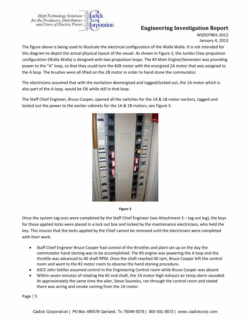
The Staff Chief Engineer, Bruce Cooper, opened all the switches for the 1A & 1B motor exciters, tagged and locked out the power to the exciter cabinets for the 1A & 1B motors; see Figure 3.
Figure 3
Once the system tag outs were completed by the Staff Chief Engineer (see Attachment 3 – tag out log), the keys for those applied locks were placed in a lock out box and locked by the maintenance electricians, who held the key. This insures that the locks applied by the Chief cannot be removed until the electricians were completed with their work.
• Staff Chief Engineer Bruce Cooper had control of the throttles and plant set up on the day the commutator hand stoning was to be accomplished. The #3 engine was powering the A loop and the throttle was advanced to 40 shaft RPM. Once the shaft reached 40 rpm, Bruce Cooper left the control room and went to the #2 motor room to observe the hand stoning procedure.
• ASCE John Settles assumed control in the Engineering Control room while Bruce Cooper was absent. • Within seven minutes of rotating the #2 end shaft, the 1A motor High exhaust air temp alarm sounded.
At approximately the same time the oiler, Steve Sourelos, ran through the control room and stated there was arcing and smoke coming from the 1A motor.
Cadick Corporation | PO Box 495578 Garland, Tx 75049-5578 | 800-931-8573 | www.cadickcorp.com

Engineering Investigation Report WSDOT#01-2012
January 4, 2013
Page | 6
• The #3 engine/generator was immediately removed from the propulsion loop and the motor room
camera was turned on to observe the 1A motor. • Once the power was removed from the 1A motor the arcing subsided. • The motor room was vented to the atmosphere to clear the smoke, and after approximately two hours
the crew went down and removed the Plexiglas cover from the motor to observe the interior and witnessed the damage to the commutator where the brushes had been left down on the commutator.
• All work was suspended at that time and the Port Engineer, Scott Mullan was notified of the incident.
The Jumbo Class propulsion system is a fixed armature circuit and can only be isolated by physically reconfiguring a set of bus links in each motor enclosure to isolate the motors armature from the bus loop. This would have to be done in order to energize only one motor on a particular loop and not the other motor. It is our opinion that this was not understood by the maintenance electricians.
To verify that all precautions and Safety standards were followed leading up to this incident, a thorough review of WFS Safety Instruction and LOTO (Lock Out Tag Out) procedures was accomplished.
• The Lock out Tag Out Manual (attachment 4) is very specific about the procedures to be followed to isolate a given circuit. The Tag out log that is maintained in the Engineering Control Room documents what equipment has been tagged out, who placed the tag, lock number and the date. It also indicates when the tag was removed, who removed it and the status of that piece of equipment.
• Our investigation found that on November 1st; o Locks were placed on the 2A,2B and #2 Standby exciter power circuit breakers. o Tags were also placed on UPSP1-4, 2A exciter, USPS2-3 2B exciter and USPS2-5 #2 Standby
exciter. o The locks and tags for the 2A exciter had to be removed prior to energizing this motor, but they
were never cleared/recorded on the Tag Out Log. This appears to be an administrative oversight by the Staff Chief Engineer who attached the locks and tags.
• What was apparent was the lack of communication between the maintenance crew and the Staff Chief Engineer regarding the steps each one took to prepare for the planned maintenance.
• Without a written document that details this maintenance evolution, the electricians rely on the Chief Engineer to properly lock out and tag out the propulsion system in a manner which eliminates any release of hazardous energy or exposes anyone to an unsafe condition.
• Because the maintenance crew is not familiar enough with the vessels propulsion system to know if the tag out was thorough, they rely on the Chief to make sure that is tagged out correctly. This maintenance task had not been done on the Walla Walla for 10 years prior to this attempt
• The electricians stated that they have done this type of maintenance many times on the other classes of vessels, but this was the first time for most of them on this vessel.
• Electrician Mark Levang is the only maintenance electrician who has done this procedure before on the Walla Walla, however he was not the lead electrician at the time.
Because the propulsion motors on the Walla Walla are connected to each propulsion loop through bus links, the motors are not isolated from propulsion voltage when their respective exciters are taken out of service.
Cadick Corporation | PO Box 495578 Garland, Tx 75049-5578 | 800-931-8573 | www.cadickcorp.com

Engineering Investigation Report WSDOT#01-2012
January 4, 2013
Page | 7
Figure 4 shows the links that are located in an enclosure which is attached to each motor. If a motor has to be isolated completely from the energized propulsion loop, these links must be removed and repositioned so that the loop stays closed, going around the motor circuit and isolating the motor armature from the loop voltage.
Figure 4
Conclusions Because the 1A motor had two sets of brushes still connected to the commutator and the loop isolation links still “in service”, the A loop voltage was applied to that motor’s armature circuit, the commutating ( interpole) windings and compensating (pole face) windings.
It is our opinion that there were four (4) proximate issues that led to this failure.
1. Insufficient communications among all involved personnel the day of the casualty. 2. The SCE Bruce Cooper was not aware that the brushes had been removed from the 1A motor 3. Insufficient understanding of the motor electrical supply system resulting in a failure to properly
disconnect the 1A motor armature or discuss the possible alternate set up as described earlier 4. A rushed schedule in an attempt to finish the work quickly and get the ferry restored to service.
Cadick Corporation | PO Box 495578 Garland, Tx 75049-5578 | 800-931-8573 | www.cadickcorp.com

Engineering Investigation Report WSDOT#01-2012
January 4, 2013
Page | 8
Figure 5
• Figure 5, shows that -- with the exciters secured and tagged out, if the propulsion A loop is energized, power is present at the A1 and A2 connections. Connections A1 and A2 can only be disconnected by opening the links as previously discussed.
• With only two sets of carbon brushes in place on the commutator and no excitation applied to the field (F1, F2) the motor would not develop enough torque to break free.
• We believe that the damaged brush set (negative polarity) initially had a higher resistance than thepositive set. When the voltage was applied, current flowed through both brush sets; however, the higher resistance of the negative brushes caused it to more rapidly heat up. As its temperature increased over that of the positive set, its relative resistance increased as did the voltage across it. This heat-resistance relationship caused the negative brush set to reach the melting point of copper much faster than the positive brush set. The resulting arcing caused a reduction in the total current; and at that point, the positive brush set would have experienced decreasing heat dissipation and never reached the point of obvious damage.
• This entire evolution, from energizing the A loop to shutting it down after smoke and arcing were observed coming from the 1A motor, lasted approximately seven minutes, as recorded by the ships alarm and monitoring system (attachment 5).
Cadick Corporation | PO Box 495578 Garland, Tx 75049-5578 | 800-931-8573 | www.cadickcorp.com

Engineering Investigation Report WSDOT#01-2012
January 4, 2013
Page | 9
Recommendations We recommend that the following steps be taken to reduce the possibility of a reoccurrence of this type of incident:
Develop a written procedure which details every aspect of a particular task.
It has been noted several times in this report that there is no written procedure for some of the maintenance performed on this vessel. A written procedure, similar to those used by the Naval Sea services and many of the large bulk carrier companies, is highly recommended.
Such a procedure details every aspect of a particular task, and includes all safety related requirements, such as Lock Out Tag Out procedures and Personal Protective Equipment required to perform the job. These procedures should be created as a joint effort, between a vessel engineer, Eagle Harbor maintenance personnel and an outside vendor, who is practiced at creating this type of document. At a minimum the procedure should include the following:
• A specific schedule for each task including the time required for completion. • The number of technicians required. • The skill set and experience required for each technician. • All required tools and equipment. • All hazards that may be encountered. • Step-by-step directions need by all involved. • Each item on the procedure should have a check box so that the person in charge can check off each
step as it is accomplished. • List the components that are being locked out not the system it is part of.
This document would cover all of the tasks required of vessel personnel, maintenance personnel and or outside contractors.
Had this type of Maintenance Procedure document been available,
1. The Chief Engineer would have known that the maintenance team had left brushes down on the 1A motor for insulation tests.
2. The maintenance team would have realized that the bus links needed to be removed prior to energizing the propulsion loop and that just securing the exciters was not enough.
3. The Port Engineer’s Department would have been aware of each step and time required to accomplish that maintenance task.
4. Planning Depts. would have a better understanding of the time and assets required to complete a specific task and could plan this maintenance with a more reasonable time of completion.
Because this type of maintenance is rarely done, relying totally on corporate knowledge is not recommended. While each individual involved in this incident did what they knew needed to be done, there was a missing
Cadick Corporation | PO Box 495578 Garland, Tx 75049-5578 | 800-931-8573 | www.cadickcorp.com

Engineering Investigation Report WSDOT#01-2012
January 4, 2013
Page | 10
factor which lead to this incident, a common reference that all involved could rely on, a procedure that had been tested and proven.
The creation of the Maintenance Procedures should include a member of each of the specialties that are responsible for that work or anyone tasked with oversight.
Provide additional training for maintenance and safety personnel.
Cadick Corporation has reviewed the Training Course for the Jumbo Class Ferry Propulsion System. This manual is a very good technical reference, but does not discuss system configuration and set up in much detail. It is designed for the engineer who has a fair to excellent knowledge base of the system already.
We envision a short training program of perhaps eight (8) hours in length. During this training, all involved personnel would be walked through the procedure for the task(s) to be performed. It should include a brief, detailed coverage of the expected safety hazards and how they can be avoided.
In addition to the eight hour training, we also recommend that annual training be implemented for affected personnel including:
1. Coverage and review of all ship’s electrical systems. 2. Review of safety procedures and policies. 3. Selected focus on issues or problems that have appeared in the period since the last training.
The provision of these types of training will help to keep personnel more focused on the technical and safety aspects of their jobs. It will also help to keep morale high.
We believe that the implementation of these recommendations will greatly reduce the possibility of a recurrence of problems such as those that are the topic of this report.
Respectfully submitted:
Micheal Turner Director of Marine Services Cadick Corporation
Cadick Corporation | PO Box 495578 Garland, Tx 75049-5578 | 800-931-8573 | www.cadickcorp.com

Engineering Investigation Report WSDOT#01-2012
January 4, 2013
Page | 11
Recognition Statement Cadick Corporation would like to express its appreciation for the support and candor of all personnel that were involved in our investigation. We are pleased to note that all personnel focused on the analysis and resolution of the problem with an eye towards implementing procedures to prevent its recurrence.
We would especially like to thank:
From the Investigation Kick Off Meeting 11/13/12:
• Elizabeth Nicoletti • Tim Browning • Scott Mullan • Ron Wohlfrom • Mike Lindsey • Vern Day • Dan Gleaves • David Gleaves • RJ Kelly • Darnell Baldinelli • George Capacci • Jean Baker • Steve Rodgers
Other Individuals with Whom We Discussed the Incident
• Bruce Cooper • Mike Lindsey • Mark Levang • Steve Carpine • Delta Electric – Tony Vacca
Cadick Corporation | PO Box 495578 Garland, Tx 75049-5578 | 800-931-8573 | www.cadickcorp.com

Engineering Investigation Report WSDOT#01-2012
January 4, 2013
Page | 12
Attachments Delta Electrics Report
Tag Out Log
Lock Out Tag Out Manual
Ship’s Alarm and Monitoring System
Statements
Motor Outline
Cadick Corporation | PO Box 495578 Garland, Tx 75049-5578 | 800-931-8573 | www.cadickcorp.com