engineer intelligence bulletin no 3 - bulletpicker.combulletpicker.com/pdf/engineer intelligence...
TRANSCRIPT

.3
LLIGEECEBULLETIN NO.3
ENGINEER SECTION
HI.EIGHTH ARMY
DECLASSIFIED

TABLE OF CONTENTS
TITLE PAGE
SECTION I - EDITORIAL, All Troops 1
SECTION II - GENERAL REPORTS FROM OPERATIONALAREAS__ 2
Cebu 2 - 29Zamboanga 30 - 32
SECTION III - ANTI-WITHDRAWAL FUSES 33Jap Naval Torpedo FEploders Used in
Land Mines 33 - 41Japanese Tail Fuse, E-l(a) 42
SECTION IV - JAPANESE USE OF MINESS 45Booby Trapped Ammunition Dump (Luzon) 45Depth Charge Road Block - Cebu City 46Improvised 'Artillery Shell' Land Mine 49Electrically Fired Controlled Road Mine -
(Panay) 49Improvised Release Type Road Mine (Negros) 49Pressure Bar Used in Road Mine (Negros) 49Japanese Mine Road Block (Negros) 49Controlled Mine Field (Panay) 49Japanese Type 90 Flare Igniter Used as a
Pull Firing Device for Aerial Bomb Mines 50
NOTICE
This document is classified as SECRET only because portions
of the contents describe the effectiveness or ineffectiveness of
Japanese tactics, techniqpes, and material against cur troops.
The material contained herein may be used for the training of
troops.
Published by
ENGINEER SECTION, HEADQUARTERS EIGHTH ARMY
in May 1945
Distributed to all Eighth Army units; GHQ, SWPA: USAFFE;
FEAF; Sixth Army; Tenth Army; Seventh Fleet; PHIBSEC; Land
Headquarters, SWPA; and Engineer Board, Ft. Belvoir, Va.

I-ALL TROOPSBecause the subject matter of this issue of the Engi-
neer Intelligence Bulletin is of general interest and ap-plication, it is being distributed to Eighth Army troopsof all branches. The contents are limited to certain spe-cific information on Japanese use of land mines an forti-cations obtained during recent operations in the SA.
The material on mines should be used by troops onlyin accordance with existing training directives, which pro-vide in general: that all combat and service troops willbe trained in precautions to be taken in the vicinity ofmines and booby traps, methods of probing for mines, me-thods of removing mines and booby traps at a safe distancewith cables, and methods of marking and guarding enemy minefields to safeguard passage of friendly troops; and thatindividuals in combat engineer units, infantry ammunitionand pioneer platoons, and infantry anti-tank platoons willbe given additional training in the recognition of minesand booby traps and in the more refined techniques of dis-arming, lifting, and destroying activated mines and boobytraps. Personnel not especially trained should not tamperwith mines of any kind, friendly or enemy.
PAGE I

"I -GENERAL REPORTS FROM OPERATIONAL AREAS
CEBU
I - General
Extensive enemy defensive installations were encountered by our troopsduring the landing on the Talisay - Tanke beach south of Cebu City but these,fortunately, were not occupied or defended by fire. On the advance intoCebu City, the same situation obtained; the city was strongly prepared fordefense with numerous street blocks, pillboxes, mines, and shelters, but waspractically undefended. Upon the approach of American forces, the Japanesepromptly withdrew into strongly prepared defensive positions in the hillsnorthwest of Cebu City. The following report on the Cebu defenses coversonly the Talisay - Tanke beach defenses, installations in Cebu City, and awell constructed road block along the Mananga River, and supplements thebrief preliminary report on Page 4 of Engineer Intelligence Bulletin No. 2.
II - Talisay - Tanke Beach Defenses
A. General layout of defenses:
1. For a complete layout of defenses, see Figure 1.
2. It will be noted in Figure 1 that all pillboxes and firing posi-tions, with two exceptions, were in one line along the edge of the coconutgrove fringing the beach. There was no depth to the position. Practicallyall of the firing positions were designed for frontal or flanking fire. Thearea between Tanke and the larger cemetery contained the heaviest concentra-tion of pillboxes, trenches, covered firing positions, and shelters. Thesecommanded the entire landing beach and offshore area. There were a few large
PAGE 2

JAPANESE DEFENSIVE POSITIONSTALISAY-"TANKE LANDING BEACH AREA, CEBU ISLAND, P.I.
LEGEND-SARSEO WIRE -X-x-X - AT DITCH 0<>04>oC.'
Q°O R 'SPLINTER PROOF SHELTER E MASSIVE SARRIER-p4-OO--
a OPEN FIRING POSITION 0 LOS PENCE --- p--4-P1TRENCH VVVVVVN RAIL PENCE 1D
f UNCR. PILL OX 4(ASPARAS 3E00 00gp
0CONCR. SHELTER - BOOBY TRAP0
WET RICE QLOG PILL BOX G'SINGLE MINE0LOG SHELTER &3 FELLED LOSE''-.-t,
SPLINTER PROOF FIRING POB. 0l' CRATER C)
WET RICE WET RICE
WET RICE
0 i hi~eavi/y crn' ad =-S area in weet ice -
RICE7
WET RICEro4 u/ar3 a" _ - -
deo1 Scl Appro+ '-ir M.
500 0° 50 .S 000 50 2 00 25 0 eeed
FIGURE I - PAGE 3


shelters back of the beach, apparently designed for CP's, but no artillery,mortar, or AT gun positions were discovered. Trenches were of simple stand-ing zig-zag or wavy types (Figure 2), generally not revetted, and with severalsplinter-proof covered bays. The concrete pillboxes and shelters ranged from7 inches to 3 feet in thickness; coconut log emplacements were from one tofour logs in thickness. Splinter-proofs generally consisted of one to twoinch lumber sheathing covered with sand or sand bags (See Figures 3 - 8).
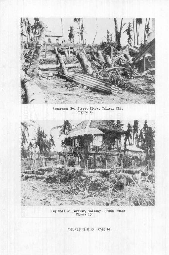
3. The two or more bands of massive AT obstacles shown on Figure 1formed a continuous AT barrier back of the beach from Talisay to Tanke in-clusive, and included AT ditches (Figures 9 & 10), log fence barriers (Figure11), steel rail fences, log "asparagus beds" (Figure 12), timber saw horses,and log walls (Figure 13). Full advantage was taken of local materials, andthe obstacles were well tied in with existing barriers. Inshore from theTalisay - Tanke road, a swampy creek parallels the road and forms an effectiveAT obstacle. In the hinterland, the extensive areas of wet rice fields canal-ized all motor movement to roads leading inland from the beach. The streetsof Talisay were blocked with craters, AT ditches, felled trees and stumps,"asparagus beds" of embedded logs, and masonry parapets.
4. Mixed 60 mm mortar shells, 75, 105, and 155 mm artillery shells,and 100 - 250 pound aerial bombs were used as AP.and AT mines of pressurecontact types. In general, they were buried upright with fuses extendingslightly above the ground and were fused for effect against personnel as well
as vehicles. Many were covered with a standard type of wooden cover (Figure14). An almost continuous band of mines extended the length of the beach be-tween the shoreline and the gun positions. Ordinarily, several rows of mines'were spaced at random within the band (Figure 15). On the sand spit in frontof Talisay a single row of bombs were placed about 15 feet apart. An addi-tional band of mines along the shore behind the spit was reported. Mineswere incorporated into road blocks in Talisay and on the roads back of thebeach (Figure 16).
5. Anti-personnel obstacles, consisting of wire entanglements and
short, pointed bamboo strips were employed (Figure 17). One band of wire ob-stacles extended the entire length of the beach. Included was one short sec-tion of underwater wire (Figure 18), which was completely submerged only athigh tide. Another strip of low wire placed in the surf covered an 880 footfrontage along the beach (Figure 18). A shallow field consisting of rows oftwo feet long pointed bamboo strips extended for about 750 feet in front ofone section of the forward line of emplacements.
6. The log boom off Tanke consisted of a double row of logs and
bamboo tied or chained together, with fish nets attached. Apparently these
nets were intended to foul the propellers of craft attempting to cross over
the boom. The boom was not mined.
7. Pillboxes, AT ditches, trenches, shelters, and massive obstacles
were concealed by utilizing the palm groves, dummy nipa huts, beach sand, palmfronds, woven fiber panels, dummy tin roofs, vines, and other plants and foliage.
Much of the camouflage was disrupted at the time of the inspection. Conscien-
tious effort appears to have been made to conceal all installations except the
AT band of felled trees back of the beach, the underwater obstacles, and the
street blocks in Talisay.
PAGE 4

DETAIL OF TYPICAL SECTION OF TRENCH, TALISAY-TANKE BEACH AREA
4 _4
:.: " rs "
~-. t4
Section of Trench, Talisay - Tanke Beach
FIGURE 2 - PAGE 5
-LEGEND-
Simple trench with spoil berm......
Splinter proof cover
Coconut trees........ .............SECTION A-A'

I
-- - - - - - - - - - - - -
-4
id* a
INORMA-
1 i1 1
N
IL
" FRONT VIEW
CONCRETE PILLBOX
TALISAY BEACH
"TOP VIEW."
Sketch of Heavy Concrete Pilibox - Talisay Beach(See Photos Page 8)
Photo of Pilibox in Above Sketch
FIGURE 3 - PAGE 6

2"x14" lumber trap doorfaced on outside with
.1/4"steel plate,closedupward by pulling cord.Same on other ports
SKETCH OF HEAVY CONCRETE PILLBOX, TALISAY BEACH(See Photos Page 8)
FIGURE 4 - PAGE 7
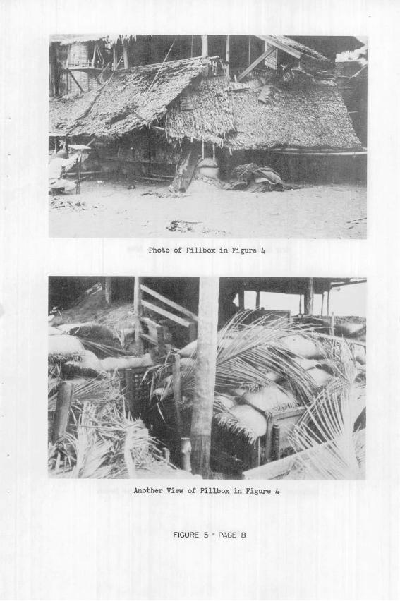
Photo of Pillbox in Figure 4
FIGURE 5 - PAGE 8

Log Shelter, Talisay - Tanke Beach Area
Splinter Proof Firing Position, Talisay - Tanke Beach
FIGURE 6 - PAGE 9

Pilibox in Corner of' Stone Wali, Talisay - Tanke Beach(See Sketch Above)
FIGURE 7 - PAGE 10
83"
It / /Y 3hgPILLBOX BUILTINTO CORNER
OF CEMETERY
WALL
/TALISAY- TAN KE
BEACH
Open

Interior of Shelter, Thlisay - Tanke Beach(See Sketch Above)
FIGURE 8 -PAGE I I
(2 ,iheotoosg sides aod top
17 (?ff hrdih: Food poZom -(?)SPosts to ,ooO-
B~-ottoot of port of good leoe!
NOTE The walls and roof of/this she//er were composed of logs and spoil. // was impossibleto determine thickness used.
SHELTER WITH FIRING PORTS TO REARTALISAY- TANKE BEACH
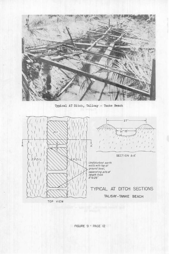
Typical AT Ditch, Talisay - Tanke Beach
-
27'
A 1 I I , / / / / l
SECTION A-A'
Undisturbed earthwa//s with top at
ground level,
separating pits oflength from
8'to26'
TYPICAL AT DITCH SECTIONS
TALISAY-TANKE BEACH
TOP VIEW
FIGURE 9 - PAGE 12
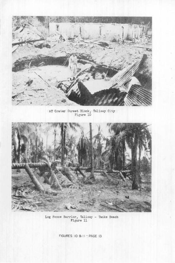
ATCrater Street Block, Talisay CityFigure 10
Log Fence Barrier, Talisay - Tanke BeachFigure 11
FIGURES 10 &8I I - PAGE 13
1 L r ^ ... T .
Asparagus Bed Street Block, Talisay CityFigure 12
61~
Log Wall AT Barrier,Figure
Talisay - Tanke Beach
FIGURES 12 8a 13 - PAGE 14

rl .l
Wood cover foundboth camouflaged -FuSE EXPOSEDand exposed _ < \
Ground line
S SHELL Two planks na//ed at 900S BURIED laid over fuse to act as
L _J pressure plates
WOOD COVER PLACED OVER MANY MINES
FIG. 14 TALISAY BEACH AREA AND MANANGA R. BRIDGE AREA
LEGEND: 0 Individual mines of 60mm,75mm,105mm,155mm shells and 100#to 250*aerial bombs
Beach Line
SPATTERN OF PORTION OF MINE FIELD ON TALISAY-TANKE BEACH
;M u,
-- I
Fl

- Shoulder-
00bombor /55mm shell
60mm artyshell buriedupright with nose fuseflush with surface
-Roadway, approx. 14'
0 0 r
Pre- cast concrete pipe 2/'highsupported by coconut logsburied in roadway
ROAD BLOCK FOUND ON TALISAY-TANKE ROAD
FIGURE 16 - PAGE 16
/2--16'Traveled read
ditch line
00
Legend: 8 She// or bomb buried verticalwith nose fuse extendingabove ground
TYPE MINE ROAD BLOCK
(Four of these found on roads inhinterland bock of Talisay beach)
NOTE: Mines covered by palm frondslying across road

Bamboo Strip Anti-personnel Obstacle, Talisay - Tanke Beach
Figure 17
,r-
Underwater Wire and Wire in Surf, Talisay - Tanke Beach
Figure 10
FIGURES 17 & 18 - PAGE 17
-". l a _ ; i. .w
.~ o -. ..

B. Effectiveness of the Defensive Systems:
1. Since the existing beach defenses were not manned, they had littleeffect on the landing of our forces except for the delay caused by mines andobstacles. The minefields along the beach destroyed several amphibious trac-tors, were responsible for some casualties in the first wave of troops andscattered casualties later, and restricted progress of the first waves overthe beach. Poor concealment of mines limited their effect. Two of the fiveexit roads to Highway No. 1 were rapidly cleared of mines and obstacles andcaused little delay.
2. Although camouflage was disrupted extensively at the time of thesurvey, existing remnants indicate that it was probably very effective againsthigh or medium altitude visual or photo observation.
C. Conclusions:
1. Japanese employment of bombs and shells as improvised AT and AP
mines was excellent. Their effectiveness was limited only by poor conceal-ment, failure to arm some shells, and failure to cover them with fire. The
75 mm shells used would have been particularly effective against personnelif they had been properly concealed.
2. The AT ditches were adequate to stop our medium tank. The logand rail barriers probably would not have stopped medium tanks or bulldozers
completely, but would have provided sufficient delay to prevent armor over-running a position covered by adequate AT and small arms fire, and made thetanks good targets for AT weapons.
3. Most of the firing positions and shelters afforded protectiononly against small arms fire, blast, shell and bomb fragments, and lightmortar fire. None of the emplacements furnished protection from direct hits
of 100 pound bombs or naval shell fire. Considered as light emplacements,the works demonstrated excellent improvisation and effective utilization of
locally available materials by the Japanese.
III - Mananga River Bridge and Road Block on Highway No. 1
A. General:
The Highway No. 1 bridge over the Mananga River southwest of Pardopresents an interesting example of an elaborate road block. The block wasintended to defend against an American advance up the east coast of the is-
land. Figures 19 - 24 give a complete description of the block. In addi-
tion to the minefield in the stream bed and the mines placed along the should-
ers of the main road (Figure 19), mines were planted along possible bypass
approaches and at random in open fields. All the mines located were either
artillery shells or aerial bombs, planted upright in the ground, camouflaged,and fused for pressure detonation.
PAGE 18

B. Discussion:
As planned, the block would have been extremely effective againstmechanized attack. The combination of the mine fields and mined road should-ers, the blown bridge, the formidable AT ditches, and the dragon teeth, allcovered by prepared firing positions would have been very difficult to re-duce had they been defended.
IV - Cebu City Defenses
A. The following data on individual installations is reported:
1. Street and Road Blocks:
a. Road shoulders and roadways were mined with aerial bombs,shells and yardstick mines (See Figure 24).
b. Some street blocks consisted of large buried marine minesor depth charges behind movable knife-rests of timber and barbed wire placedacross the street (See Figure 25).
c. Railroad rails supported by heavy concrete posts or logsand extending across streets were used as blocks. These generally were tiedin to stone buildings, walls, or other natural flanking obstacles (See Figure26).
d, Heavy concrete posts staggered across streets at intervalsprohibiting the passage of vehicles or tanks were employed (See Figure 27.a & b).
e. Log crib walls were filled with debris, logs and rubble(See Figure 28).
f. Heavy log posts were set into the pavement and lashed to-gether by cables.
g. Aerial bomb and shell mines and wire obstacles were incor-porated into many of the blocks described above.
2. Firing Positions:
Many road blocks and street tangents were covered by MG andrifle positions of the open parapet, splinter-proof, or concrete pillboxtypes; or by MG and rifle positions built into buildings and walls. Forcharacteristic positions; see Figures 29 & 30.
B. Conclusions:
1. Had Cebu City been defended and the barriers covered by AT, MG,and rifle fire, the obstacles described above would have been very effectiveagainst personnel, vehicles, and tanks. Undefended, they caused only minordelay and very few casualties to vehicles and personnel.
2. The Cebu City defenses indicate that the Japanese are well in-doctrinated in the development of the potential strength of cities as defen-sive positions.
PAGE 19

LEGEND
SURFACED HIGHWAYSECONDARY ROADS ALL WEATHER=-=SEASONAL ROADFOOT PATH ----- -------------RIVER BED BOUNDARY - -- - -
HIGH CLIFF RIVER BED BOUNDARY- -STREAM
PILLBOXOPEN FIRING POSITION --TRENCHES VWHNWWWVDRAGONS TEETH "......ANTITANK DITCH-OMINE FIELD -o--o-o---o-INDIVIDUAL MINE X
SKETCH OF MANANGA RIVER ROAD BLOCK
FIGURE 19 - PAGE 20

AT Ditch and Dragon Teeth, Mananga River Bridge
FIGURE 20 - PAGE 21
25' APPROX.-( N>"'
TYPICAL CROSS- SECTION-AT DITCH AT MANANGA R. BR.

Destroyed Bridge over Mananga River on Highway No. 1.
Dragon Teeth, Mananga River Bridge(See Figure 22)
FIGURE 21 - PAGE 22
,L ~ ~eJ~r-e
UI-CC~~ ~ ~ '
Ire:
---- ,~'
_t:~Cii~r~Y-Pjk

CONCRETE TETRAHEDRON-MANANGA R. BRIDGE-HIGHWAY NO. I
FIGURE 22 PAGE 23
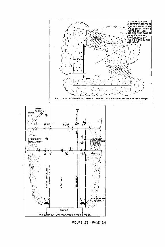
FIGURE 23 - PAGE 24
" CONCRETE FLOOR8 CONCRETE ROOF WITH
PILL BOX COVERING AT DITCH AT HIGHWAY NO. I CROSSING OF THE MANANGA RIVER

---- 24 'Approx-. -
Figure 24
Type of Knife-Rest Used in Cebu City Street BlocksFigure 25
FIGURES 24 8 25 - PAGE 25
/2'A oprox.
Roadway -Curb-_ line
2 Yardstick mines Buildingburied in roadway
end to end
ROAD BLOCK IN CEBU CITY

Remains of Steel Rail Type Street Block, Cebu City
Figure 26
-Surfaced roadway--
Five-strand fence Lsupported by concrete xiblocks _ x_ E. l'
B rb~ed wire strung on steel
pickets inbedded in top ofconcrete posts
-Concrete blocks 32'x3Y2 x3'aboveground embedded in street
'hlgh masonry wall
fgnr sneiter
Port''
CEMETERY--
y 9'high masonry wall
OPEN LOT
STREET BLOCK IN CEBU CITY(NOTE: Mines were probably incorporated into this block)
Figure 27 A
FIGURES 26 & 27A - PAGE 26
4'highmasonry wa/I
_II I

Figure27B
Log Crib Wall Obstacle, Cebu CityFigure 28
FIGURES 27B 8 28 - PAGE 27
Massive concreteposts
SLight bunker
STREET BLOCK AT LAHUG RJ(Environs of Cebu City)

Concrete Pillbox, Cebu City(See Sketch Above)
FIGURE 29 - PAGE 28
A\Jo7
FRONT VIEW
NOTE: - Walls are reinforced withpanels of wrought iron fence.
ALL-CONCRETE PILLBOX ON HWY NO. I
SW OF CEBU CITY
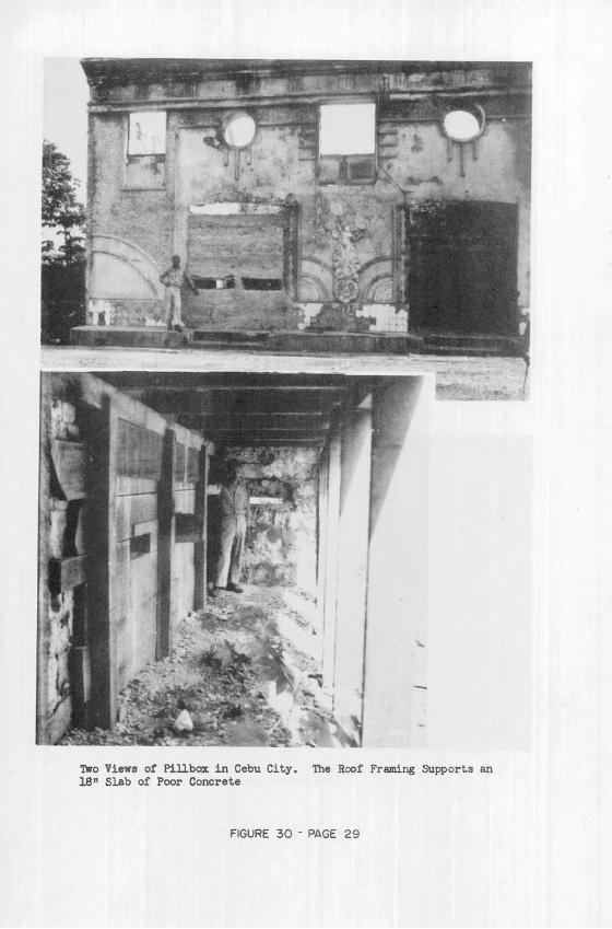
Two Views of Pillbox in Cebu City. The Roof Framing Supports an
18" Slab of Poor Concrete
FIGURE 30 - PAGE 29
L. r
1 JI~ s

ZAMBOANGA
This report supplements material presented on Pages11 to 47 of Engineer Intelligence Bulletin No. 2, April1945, and covers the period 20 March to 25 April 1945.
Enemy mine operations for the period were on a muchsmaller scale than in previous periods. The fact that ourtroops had left the existing road net and were advancinginto the hills, building their own supply roads as theyprogressed, probably accounts for this reduction in enemymine activity.
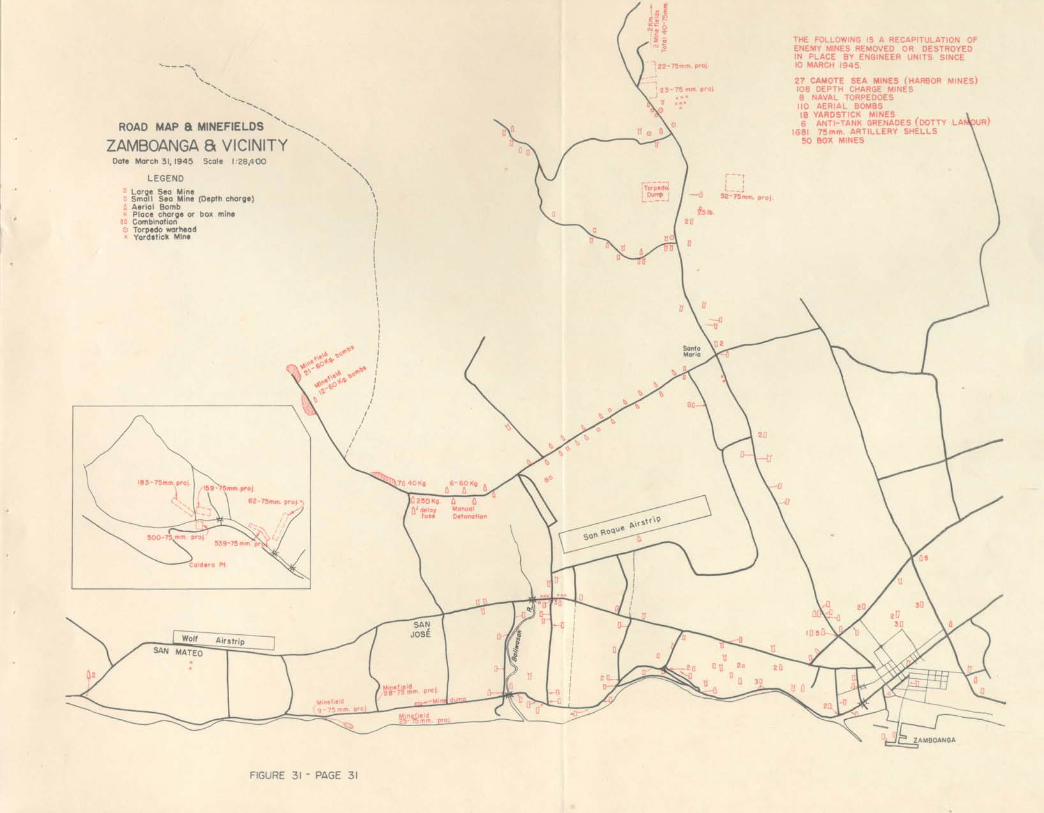
Figure 31 supplements the mine location chart pre-viously published on Page 35 of Engineer IntelligenceBulletin No. 2. Figure 32 describes in detail the firstenemy mine field encountered in the Zamboanga area inwhich a definite mine pattern was used. Note the wirefences marking the fields. These fences probably weredesigned to prevent animals from detonating mines. Itwill also be observed in Figure 31 that the Japaneselaid many mine fields across country away from the roads.
During the period in question the enemy used the 75mm artillery shell mine in large quantities and in suchisolated areas that guerrilla forces were given instruc-tions in the disarming and removal of this simple typeof mine and were able to perform these tasks effectively.
PAGE 30
N
ROAD MAP & MINEFIELDS -,
ZAMBOANGA 8 VICINITY 'Date March 31,1945 Scale 1:28,400
LEGEND
SLarge Sea Mineo Small Sea Mine (Depth charge)6 Aerial BombSPlace charge or box mine
O0 Combination0 Torpedo warheadx Yardstick Mine
23-75 mm. proj.J x
t K
THE FOLLOWING IS A RECAPITULATION OFENEMY MINES REMOVED OR DESTROYEDIN PLACE BY ENGINEER UNITS SINCE10 MARCH 1945.
27 CAMOTE SEA MINES (HARBOR MINES)108 DEPTH CHARGE MINES8 NAVAL TORPEDOES110 AERIAL BOMBS18 YARDSTICK MINES6 ANTI-TANK GRENADES (DOTTY LA U
1681 75mm. ARTILLERY SHELLS50 BOX MINES
N\
N
52-75mm. proj.
FIGURE 31 - PAGE 31


MINEFIELD PATTERN
Minefield located at road junction
(3a.7-(42. 5)Mindanao- Cld era Sheet
Coconut
Grove
completed
mmne
4 MNEFL No.2
-- San Ramon Kawit 3.5 Miles-
MINE FIELD No. I (Removed)
Consisted of 159-75mm. type in 3 rows evenly spaced at 13'Mines in rows as indicated in numbers evenly spaced at 6-6
MINE FIELD No.2 (emoved)
Follows same measurement a pattern-consisted of 183-75mm
type artillery shells
MINE FIELD No. 3
6 mines removed from road shoulders-remainder posted for guerillas to completeUndetermined number believed to follow same pattern as I &2All mine fields surrounded by single strand of barbed wire approx. 3' in height.Total mines removed 348
MINEFIELD No. 3
Left for removal by guerillas
11 f

ItI ANTI-WITHDRAWAL FUSESJAP NAVAL TORPEDO PLODERS USED IN LAND MINES
A. General:
Preliminary reports on the use of Japan-ese naval torpedo exploders in torpedo warheadland mines have been disseminated in EngineerIntelligence Bulletin No. 2, pages 17, 18, and47. More detailed information is now avail-able. The information presented herein is NOTintended as instructions for disarming suchassemblies, but as convincing proof that NOPERSONNEL EXCEPT QUALIFIED NAVY EXPERTS SHOULDATTEMPT TO DISARM, RBI(OVE, OR MOVE THESE EX-PLODERS IF ATTACHED TO TE BOOSTER CHARGE, AWARHEAD, OR ANY OTHER EXPLOSIVE CHARGE. Theonly exception to the above rule is that ifthe tactical situation demands removal and ifit is impracticable to destroy the warhead inplace, it may be dragged out of position bytank-drawn cables. Although the two types ofexploders to be described are equipped withpostive and effective safety devices, internalmodifications which are not visible externallyand which render the safety devices either in-effective or cause detonation of the chargewhen the safety devices are manipulated, canbe made easily in the field with simple tools.Although the modification made in the assemb-
lies found at Zamboanga were easily discern-able, the fact remains that the Jap is awareof the possibilities of these exploders andthat he may be expected to use more refinedtechniques in the future.
PAGE 33

B. Type 90 Model 2 Exploder in Type 91 Warhead:
1. Description and Internal Functioning:
Figure 33 a consists of general views of components of theexploder. The exploder-booster assembly may be broken down into four maincomponents:
a. The light aluminum top cover plate.
b. The bronze top casting, upon which are mounted the waterdriven arming impeller, the gear train to the arming spindle ("b", Figure33 b), the arming spindle ("c", Figure 33 b), and the positive safetydevice of the assembly ("d" & "e", Figure 33 b)
c. The inertia exploder assembly which is housed in thecylindrical aluminum main housing ("f", Figure 33 b) and mounted on abrass base plate which is connected to the bottom of the main housing byscrews.
d. The cap-primer-booster assembly ("r" - "s" - "q", Figure33 b) which is screwed into the base plate by annular threads at the topof the body.
Reference Figure 33 b, the base plate "g" and the striker housing"g'" are fastened together rigidly. The striker shaft "m" is threadedloosely to a striker headpiece "n". The striker shaft is free to revolveunder action of the arming spindle "c", the shank of which engages loose-ly inside the square cross-sectioned cavity in the striker shaft. Theheadpiece "n" cannot revolve because of two attached lugs which run invertical slots cut into the striker housing "g'". The striker spring "p"is contained by the striker headpiece at one end and on the other nid bythe striker spring retaining plug "t" which screws inside the strikerhousing. The locking sleeve assembly "i" rests on the floor of the heavyinertia cup "h" and in its normal position retains the two ball bearingdetents "o", thus preventing downward movement of the striker headpiece.Tipping of the inertia cup by an impact from any direction causes upwardmovement of the locking sleeve, allows the detents to fall outward, andreleases the striker assembly "m - n". The locking sleeve is held inplace by the spring "j", which bears against the nut "k" at the upper endof the spring.
PAGE 34

A~w
Group 2 Group 3p. l: Torpedo used at Zamboanga.
Note wire to bail and wire leadingto outside; both were connectedto locking sleeve.Gp. 2: Foreground; top cover plate.
L. to R.; top casting assembly, mainw housing, inertia exploder assembly.Gp. 3: Inertia exploder assemblyparts. Rear, L. to R.; strikerspring retaining plug, safety sleeve,locking sleeve spring nut, lockingsleeve spring, locking sleeve, in-ertia cup. Front, L. to R.; inertiaassembly base plate and striker housing,
Group 4 striker spring, striker shaft, strikerheadpiece.
Gp. 4: L. to R.; inertia exploderassembly, top view with bail in safeposition.
TYPE 90, MODEL 2 TORPEDO EXPLODER- PARTS-
FIGURE 33A-PAGE 35

-LEGEND-
a-Top Costingb-Arming Spindle Gear
c-Arming Spindle f
d- Safety Ring Plunger A
e-Safety Ring ef- Main Housing
g-Inertia AssemblyBose Plate
g'- Striker Housing
h-Inertia Cup
/ -Locking Sleeve Assemblyh
j-Locking Sleeve Spring
k-Locking Sleeve SpringNut
- Safety Sleeve g
m- Striker Shaft o
n-Striker Headpiece
o-Ball Bearing Detents -
p Striker Spring
q- Booster Container
r-Primer
t-Striker Spring sRetaining Plug
u-Firing Pin -
v-Locking SleevePlungers
PARTIAL SECTION, TYPE 90, MODEL 2, JAPANESE TORPEDO EXPLODER
FIGURE 338-PAGE 36

Var abte Oelay Arming Shoft
ImpBller-
Bil
P easure Disk
.o
Group I Group 2
Variable Dely Arming S
PlungerFrom~
Bana
Group 3 Group 4
Gp. 1: L. to R.; inertia exploder assembly, top view ofexploder with bail in armed position.
Qp. 2: L. to R.; exploder, traveling plug, connectingring, dummy primer, booster, traveling cap for booster.
Gp. 3: Foreground; top cover plate. L. to R.; top cast-
ing assembly, main housing, inertia exploder assembly.
GiJ1 Rear row, L. to R.; locking sleeve spring nuts (2),striker spring retaining plug, locking sleeve spring,locking sleeve, inertia cup. Front row, L. to R.; inertiaassembly base plate and striker housing, striker spring,assembled striker shaft and striker headpiece.
"CEBU TYPE" TORPEDO EXPLODER-PARTS-
FIGURE 34A-PAGE 37

PARTIAL SECTION "CEBU" TYPE TORPEDO EXPLODER(For legend of parts see figure 33b)
FIGURE 34B-PAGE 38
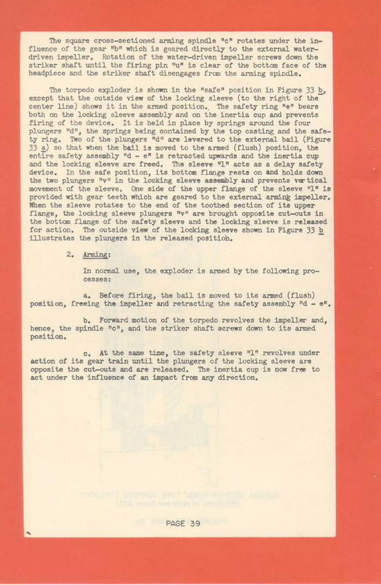
The square cross-sectioned arming spindle "c" rotates under the in-fluence of the gear "b" which is geared directly to the external water-driven impeller. Rotation of the water-driven impeller screws down thestriker shaft until the firing pin "u" is clear of the bottom face of theheadpiece and the striker shaft disengages from the arming spindle.
The torpedo exploder is shown in the "safe" position in Figure 33 b,except that the outside view of the locking sleeve (to the right of thecenter line) shows it in the armed position. The safety ring "e" bearsboth on the locking sleeve assembly and on the inertia cup and preventsfiring of the device. It is held in place by springs around the fourplungers "d", the springs being contained by the top casting and the safe-ty ring. Two of the plungers "d" are levered to the external bail (Figure33 a) so that when the bail is moved to the armed (flush) position, theentire safety assembly "d - e" is retracted upwards and the inertia cupand the locking sleeve are freed. The sleeve "1" acts as a delay safetydevice. In the safe position, its bottom flange rests on tad holds downthe two plungers "v" in the locking sleeve assembly and prevents verticalmovement of the sleeve. One side of the upper flange of the sleeve "1" isprovided with gear teeth which are geared to the external arming impeller.When the sleeve rotates to the end of the toothed section of its upperflange, the locking sleeve plungers "v" are brought opposite cut-outs inthe bottom flange of the safety sleeve and the locking sleeve is releasedfor action. The outside view of the locking sleeve shown in Figure 33 billustrates the plungers in the released positioh.
2. Arming:
In normal use, the exploder is armed by the following pro-cesses:
a. Before firing, the bail is moved to its armed (flush)position, freeing the impeller and retracting the safety assembly "d - e",
b. Forward motion of the torpedo revolves the impeller and,hence, the spindle "c", and the striker shaft screws down to its armedposition.
c. At the same time, the safety sleeve "1" revolves underaction of its gear train until the plungers of the locking sleeve areopposite the cut-outs and are released. The inertia cup is now free toact under the influence of an impact from any direction.
PAGE 39

3. Employment as a Booby Trap Firing Device:
There are several ways the exploder may be booby trappedwithout any external evidence to indicate that it is dangerous. Twomethods are presented below (NO ALLIED PERSONNEL SHOULD ATTEMPT TO SETSUCH TRAPS):
a. Remove the top casting assembly and arm the strikerassembly manually. Release the locking sleeve plungers by rotating thesafety sleeve "1" by hand. Rotate the bail to its armed (flush with top)position and secure it by a safety pin. At about the point "A" (Figure33 b) on the bottom surface of the safety ring, braze a short, pointedbrass contact plug of such length that in the retracted position Of thesafety ring the plug will barely clear the top periphery of the inertiacup. Carefully assemble the top casting assembly to the rest of the ex-ploder. In this case, if the bail is released to its "safe" position, theplug will tip the inertia ring by pressure at one point, the lockingsleeve will be lifted, and the firing pin released.
b. Place the exploder in a vertical position. Removespring "j". Arm the striker assembly manually as in sub-paragraph a,above. Remove the safety ring "e". Reassemble carefully. In this caseall safety and delayed arming devices are rendered useless. Removal ofthe spring "j" makes the exploder so sensitive that a moderate jar oreven careful displacement of the exploder from its vertical position willrelease the firing pin.
C. Unidentified Torpedo Exploder Found at Cebu:
An inertia type torpedo exploder similar to the type found onZamboanga was captured at Cebu (Figure 34 a & ). It was not used in aland mine but is described because it is suitable for employment in thesame manner as the Type 90, Model 2, Exploder.
The inertia firing mechanism of this type has the same componentsas the Type 90 with minor variations. The principal variations are in theinertia cup which has a circular instead of an oval base and in the lock-ing sleeve which is tubular and has no arms or other fixtures. The arm-ing of the striker assembly is accomplished in the same manner in bothtypes.
The safety delayed arming assemblies of the two types are almostentirely different except for the method of arming the firing pin. Thesafety cam "A" (Figure 34 b) is the only postive safety device. As shownin the figure, it holds down the locking sleeve. It is actuated by two
PAGE 40

power trains. One train, a delayed arming train, is operated by the rota-tion of the water impeller. After a variable number of revolutions of theimpeller, cam "A" revolves so as to clear the locking sleeve. The othertrain, a safety device, is a ccplicated lever-plunger-gear-cam arrange-ment which is operated by moving the bail from the armed to the safe posi-tion. Since the delayed arming train leads to cam "A" through the ratchetgear "B" (Figure 34 b), whatever the status of the delayed arming train,moving the bail to the safe (vertical) position will return cam "A" to thesafe position without interference.
Two other refinements, not present in the Type 90 Exploder, areincorporated into this device. A vertical shaft mounted in the top cast-ing serves as a variable delay arming device and is part of the delayedarming train. Fixed to the lower end of this shaft is a circular cam witha section cut away so that when a lever arm riding on it falls off intothe cut-away portion, a clutch in the delay arming train is engaged, andthe train goes into operation. The vertical shaft is geared to theimpeller and the number of revolutions required to engage the delayed arm-ing train can be regulated at will at any stage of the operation bysetting the shaft in the desired position. The other refinement consistsof an external brass disk floating on a rubber diaphragm mounted on thetop casting (Figure 34 a) and connected through the diaphragm by screwsto a contact point inside the body. The assembly is held outward againstthe diaphragm by a very heavy spring. If pushed inward by a heavy pres-sure, the contact point bears on a lever which actuates another freelever, which in turn rotates cam "A" to a safe position and holds itthere. It is presumed that this device is designed to prevent operationof the exploder if the torpedo dives too deep.
It is obvious that this exploder can be booby trapped by methodssimilar to those suggested for the Type 90 and that A CHARGE FUSED BYTHIS EXPLODER SHOULD NOT BE HANDLED OR MOVED, EXCEPT IN CASES OF EMER-GENCY, AND THEN ONLY BY CABLES DRAWN BY A TANK FROM A SAFE DISTANCE WITHFULL EXPECTATIONS OF IT EXPLODING. In case such action is necessary,extreme caution should be used in connecting the cables.
D. Precautions:
All personnel should be able to recognize these two torpedo ex-ploders and, upon discovery of a charge fused with one, post a guard andcall a bomb disposal or mine expert. As an example of the power of awarhead, one exploded on the ground surface at Zamboanga made a crater 25feet in diameter and 12 feet in depth.
PAGE 41

JAPANESE TAIL FUSE, E-l(a)
(Formerly known as B-7(a))(See Figure 35 a & b)
In normal operation, on release from theplane the arming vanes rotate the arming spindleclockwise and unscrew it from the inertia block,which is keyed to the body to prevent rotation.The flange of the arming spindle prevents thespindle and vanes from coming completely off thefuse body. Upon impact, the inertia block movesdown against the creep spring. As soon as thetop sinks flush with the top of the lower fusebody, the trigger is free to pivot under the in-fluence of the trigger spring and the canningaction of the striker notch. It pivots just farenough for the lip on the trigger to slide overthe top of the inertia block. The striker isnot quite released because rotation of the trig-ger brings the longer trigger arm to bear againstthe wall of the fuse pocket. In this position,the fuse is armed.
If any attempt is made to withdraw the armedfuse from its pocket by unscrewing it, the trig-ger will pivot further when it cnmes oppositethe annular groove in the fuse pocket wall. Whenthe trigger falls into this groove, it releasesthe striker. Under the action of the firingspring, the striker will fire the primer, set-ting off the explosive train.
The visible portion of this fuse, as it isseated in the bomb, is different from any otherJapanese fuse body known by this office. Thefuse can be armed easily by manual operation.NO ONE SHOULD ATTEMPT TO UNSCREW THIS FUSE FROMTHE BOMB UNDER ANY CONDITIONS.
PAGE 42

SAFETY FORK
RMING VANES
-ARMING SPINDLE
UPPER FUSE BODY
TRIGGER 8TRIGGER SPRING
STRIKER NOTCH
STRIKER BODY
STRIKER SPRING
STRIKER
PRIMER
.-SPRING TYPE DETENT
.--- INERTIA BLOCK
---- LOWER FUSE BODY
-- CREEP SPRING
-- RELAY PELLET
i- DETONATOR (GAINE)
JAPANESE TAIL FUSE E-I A
ANTI- WITHDRAWAL(FORMERLY KNOWN AS JAPANESE TAIL FUSE B-7(a))
FIGURE 35A-PAGE 43

FIRED POSITION
JAPANESE TAIL FUSE E-IA
ANTI- WITHDRAWAL
(FORMERLY KNOWN AS JAPANESE TAILFUSE B-7(a))
FIGURE 35B-PAGE 44

I3" JAPANESE USE OF MINESBOOBY TRAPPED AMMUNITION DUMP (LUZON)
The following extract is taken from XIV Corps Periodic Report No. 92:
"Retiring Japanese troops on - - - Luzon ingeniously booby trappedthree sizeable stacks of munitions - - - - - - - - - - The existence ofconcealed detonating mechanisms in this particular location was not real-ized until the price of inquisitiveness and lack of knowledge on the sub-ject had been paid. At the scene, the shattered bodies of two civiliansand a dog were grim reminders of what may happen to the unwary and unwise.
"An investigation by technical intelligence personnel of the remain-ing munitions in the area revealed two other sizeable stacks to be cleverlybooby trapped in the following manner: (See Figure 36).
"The munitions booby trapped consisted of 75 boxes of Type 99,7.7 mm rifle and MG ammunition, and 15 boxes of Type 89, 50 mm grenades.The total of 90 boxes was neatly stacked six boxes high within a revetmentcut into the side of the hill. This revetment was only large enough forthe munitions. Entrance and encirclement was not possible on the groundlevel. Inspection could be made only from one end and above. From a-top the embankment, the site resembled a poor attempt at concealment of abunker. Loose dirt, twigs, and grass were thrown on top of a roof which con-sisted of two sheets of corrugated iron and a plywood door, presumably fromone of the dwellings near by. In this apparent casualness of preparation
PAGE 45

lay the shrewdness of the act. Fastened beneath the main components of theroof to long branches were the strings of six pull type friction ignitersfixed in improvised box type mines. These mines were placed directly ontop of the stacks of munitions and carried the entire weight of the roof.Therefore, any attempt to move any portion of the covering material wouldprobably pull at least one of the igniters, detonate the picric acid con-tents of the box mine, and initiate the explosion of the ammunition.
"In the same area one of these mines was placed in an empty woodenbox with a camouflage net wrapped around it concealing the mine entirely.The friction igniter was tied to the net. Should the net be unrolled, theigniter would undoubtedly be pulled."
DEPTH CHARGE ROAD BLOCK - CEBU CITY
(See Figure 37)
In the harbor area at Cebu City, eleven road blocks of the same generalpattern were found. They consisted of combinations of three elements, asfollows:
a. One or two depth charges buried in the street, placed in near-by bomb craters, or placed on the ground along side the block and camouflaged.These were fused with standard Japanese electric blasting caps.
b. One or more actuating assemblies, consisting of the standardelectro-chemical lead horn type fuse assembly for the Japanese single-hornbeach mine. Generally, the lead horn assemblies were set into the top ofconcrete tetrahedrons 8" in height and about 12" square at the base and 10"square at the top. A lead-covered two wire electrical cable entered the con-crete on the-top surface of the tetrahedron and at the base of the lead horn.This cable was connected to the leading wires of the electric blasting capin the depth charge.
c. Two or three heavy timber and barbed wire knife-rest sections.
Often the concrete tetrahedrons were buried beneath the wire obstaclesand were attached by a trip wire to either the wire obstacle or to each other.In such cases, the mine could be detonated either by crushing the lead hornby pressure or by bending the horn by exertion of a strong pull on the tripwire.
These road blocks were analysed easily and were disarmed by first cut-ting the electric leading wires, then unscrewing the lead horn in a clock-wise direction and removing the electric fuse from the fuse well of the depthcharge. Finally, the depth charge, wire obstacles, and concrete tetrahedronswere removed from the roadway.
PAGE 46

BOOBY TRAPPED AMMUNITION DUMPEND VIEW OF REVETMENT CUT AWAY
SHOWING AMMUNITION WITH BOX MINE ON TOP
FIGURE 36-PAGE 47
Enemy
Pull wire
cried concrete tetrahedrondhorn chemic al battery -
y screwed into well on topending above street level
Roadway
OPERATION: Lead horn is broken by pull on wire obstacle or by running overit. Current is generated in lead horn battery assembly andtransmitted to electrical detonator of underwater mine.
NOTE:This is drawn from a verbal description. Variations of thisblock were reported which had two or more small tetrahedronswith lead horns and mine set in centerof roadway.
STREET OBSTACLECEBU CITY
FIGURE 37-PAGE 48
Small twith lecassemband ex)
'Buried /aoge or smallunderwater barrel mineset for ele trical detonation

IMPROVISED 'ARTILLERY SHELL' LAND MINE
Figure 38 is a schematic drawing of a typical improvised pressure typeland mine found on the island of Jolo, Sulu Archipelago, P.I. The mines,as placed, were not concealed nor camouflaged and consequently were easilydetected and removed.
The mine is constructed by inverting an artillery shell case over theshell which has the nose fuse and nose plug removed. The fuse well of theprojectile nose rests against the black powder booster in the base of theshell case. An open top wooden box, inverted and with a nail driven throughit, is then placed over the base of the shell case so that the nail restson the shell case primer. This complete assembly is then placed as shown inthe figure to function as a pressure type road mine, resting approximatelyflush with the ground surface.
The following procedure is suggested tentatively as a method for removalof such a mine:
Check for external booby trapping by excavation and for internalpull device by careful visual inspection. Remove wood cover if careful mani-pulation indicates that it is free. If the primer is intact, remove theshell case. The mine should now be safe to handle. If the wooden cover doesnot lift freely, or if the shell case primer has been tampered with, destroyin place if possible.
ELECTRICALLY FIRED CONTROLLED ROAD MINE (PANAY)
Figure 39 is self-explanatory. This principle of pulling a bare wirethrough a metal tube to complete an electrical firing circuit is a commonJapanese expedient.
IMPROVISED RELEASE TYPE ROAD MINE - NEGROS
Figure 40 is self-explanatory. Where light wire or cord is used forthe trip wire, it is probable that the trip wire would break upon being hitand the mine would be actuated.
PRESSURE BAR USED IN ROAD MINE (NEGROS)
Figure 41 is self-explanatory.
JAPANESE MINE ROAD BLOCK (NEGROS)
Figure 42 is self-explanatory.
CONTROLLED MINE FIELD (PANAY)
Figure 43 is self-explanatory.
PAGE 49

JAPANESE TYPE 90 FLARE IGNITER USED AS A PULL FIRING DEVICE FOR AERIALBOMB MINES (See Figure 4A)
The following report is bases on XI Corps G-2 Weekly Report No. 7:
On Luzon, numerous aerial bombs were found used as land mines andbooby traps. A common improvisation was the use of the Japanese Type 90Flare Igniter with 50, 100, and 250 kg. bombs.
This igniter requires only minor modification to make it suitablefor use in a bomb. The only components of the Type 90 Flare used are theconical cap, a thin brass disk, and the striker mechanism. In addition, ablasting cap, packing material to act as a filler around the striker mechan-ism, and a little powdered picric acid, are required. The packing materialis composed of toilet tissue wrapped tightly around the striker mechanism.Friction tape is used to keep the paper from unwinding. The entire deviceis wedged into the bomb nose. The cone is wired to the bomb by utilizingthe two screw holes on the cone and the suspension lugs and band on the bomb.The brass disk prevents the striking mechanism from being pulled from thebomb.
A fairly stout pull on a well placed trip wire is sufficient to pullthe striker release assembly from its housing. When the assembly clears thehousing, the striker release arm fly apart and the striker is released. Theblasting cap is taped to the percussion cap and acts as a booster. The capis supplemented by powdered picric acid dropped into the gaine pocket beforethe entire device is inserted.
PAGE 50
/Noil
(Schematic-not to scale)
IMPROVISED 'ARTILLERY SHELL'FIGURE 38
LAND MINE
FIGURES 38 8 39-PAGE 51
MINE DETAIL
IMPROVISED JAPANESE MINE, ELECTRICALLY FIREDPANAYFIGURE 39
SEE DETAIL 'A'
100 kg. bomb stick, held in place by stones, supports trip wire
fatened
v to stake
Jap telephone wire or cord
SECTION A-A'
vane partially unscrewed
trip wire stretched taut
S -strip of inner tube
metal strap holdinginner tube to fuse
DETAIL 'A'
IMPROVISED JAP RELEASE TYPE ROAD MINE(NEGROS)
FIGURE 40-PAGE 52
FIGURES 41 & 42-PAGE 53

DETAIL OF MINE CONTROLLED FROM PILLBOX(5 ON PLAN) SKETCH OF MINE FIELDELECTRIC WIRE 2' SECTION OF RAIL SCHOOL STREET ILOILO PANAY P.I.USED ASTRIP NOT DRAWN TO SCALE 24 MARCH45RELEASE 1 "x3" WOOD GUIDES
LEGEND
2"x4"BOLTED I JAP EMPLACEMENT 5 REMOTE CONTROL
2 JAP TRENCHES OPERATED
5 I 3 BARBED WIRE FENCE 6 TRIP WIRES RUNNING2"x4" TRIP AND GATE FROM MINES TORELEASE LOCATIONS OF PRE- CONTROL BOXES
VIOUSLY REMOVEDMINES.
IMPROVISED WOOD BOX MINE MINBURIED AND TAMPED WITH ROCKS
'r CONCEALED WITHPIECE CORRUGATED) SHEET METAL.
CT; 4"x8 BURIEDm IN GROUND
x
ID -- 624'
m X IJ 6 SEE DETAILED6 DRAWlNG "
" . . . .nA r-l, n A

TRIP
TYPE 90 FLARE IGNITER MODIFIED FORUSE IN AERIAL BOMB
FIGURE 44- PAGE 55