engine throttle with display and monitoring · pdf fileengine throttle with display and...
TRANSCRIPT

ELA200 Rev171106
1
FIRE RESEARCH CORPORATIONwww.fireresearch.com
26 Southern Blvd., Nesconset, NY 11767TEL 631.724.8888 FAX 631.360.9727 TOLL FREE 1.800.645.0074
ENGINE THROTTLEwith DISPLAY
and MONITORING SYSTEMMODEL: ELA200
Document Number:XE-ELA2PM-R0A

ELA200 Rev171106
2
CONTENTS Table of Contents
CONTENTS ................................................................................................................ 2INTRODUCTION ...................................................................................................... 4
Overview ................................................................................................................ 4Features .................................................................................................................. 4Specifications ......................................................................................................... 5
GENERAL DESCRIPTION ....................................................................................... 6Controls and Indicators .......................................................................................... 8
INSTALLATION ...................................................................................................... 10Install Control Module ......................................................................................... 10Install Engine Sensors .......................................................................................... 10Install Buzzer ....................................................................................................... 10Install High Idle Kit ............................................................................................. 10
OPERATION ............................................................................................................ 12Throttle Control Mode ......................................................................................... 12Governor Control Mode....................................................................................... 12Power-up .............................................................................................................. 12Controls ................................................................................................................ 13Detailed Information ............................................................................................ 14High-Idle .............................................................................................................. 15
PROGRAMMING .................................................................................................... 16Access Password Protected Programs ................................................................. 18
CALIBRATION ........................................................................................................ 20Engine RPM (Code C3) ....................................................................................... 21
WIRING .................................................................................................................... 22Connectors and Cables......................................................................................... 22Secondary Controller, Cables and Connections ................................................... 23Cummins Harness Connections ........................................................................... 24Detroit Diesel Harness Connections .................................................................... 25Navistar Harness Connections ............................................................................. 27Navistar / International Chassis Harness Connections ........................................ 28Caterpillar Harness Connections ......................................................................... 29Ford Harness Connections ................................................................................... 31Mack Harness Connections ................................................................................. 34Scania Harness Connections—Type A ................................................................ 36Scania BCI Harness Connections—Type D ........................................................ 37Mercedes Harness Connections ........................................................................... 38John Deere Harness Connections ........................................................................ 39MAN Harness Connections ................................................................................. 40IVECO Harness Connections .............................................................................. 41High-Idle Wiring .................................................................................................. 42
FLYBACK DIODE INFORMATION ...................................................................... 43

ELA200 Rev171106
3
List of Tables
Table 1. Error Codes ................................................................................................ 13Table 2. Fault Warning Codes .................................................................................. 13Table 3. Calibration Codes Quick Reference Chart ................................................. 20
List of Figures
Figure 1. Controls and Indicators ............................................................................... 9Figure 2. Control Module Mounting Dimensions.................................................... 11Figure 3. Connectors ................................................................................................ 22Figure 4. Connector Wiring ..................................................................................... 23Figure 5. Cummins ELA201 Wiring ........................................................................ 24Figure 6. Detroit Diesel ELA202 Wiring ................................................................. 25Figure 7. Detroit Diesel ELA202 Wiring Governor Control Mode ......................... 26Figure 8. Navistar ELA204 Wiring ........................................................................... 27Figure 9. Navistar/International Chassis ELA204 Wiring ........................................ 28Figure 10. Caterpillar ELA205 Wiring ..................................................................... 29Figure 11. Ford 6.7L ELA206 J1939 Translator Module Wiring ............................. 32Figure 12. Ford 6.7L ELA206 PCM Wiring ............................................................. 33Figure 13. Mack ELA207 Wiring ............................................................................. 34Figure 14. Mack ELA207 Wiring Governor Control Mode ..................................... 35Figure 15. Scania ELA208 Wiring—Type A ............................................................ 36Figure 16. Scania BCI ELA208 Wiring—Type D .................................................... 37Figure 17. Mercedes ELA210 Wiring ....................................................................... 38Figure 18. John Deere ELA216 Wiring .................................................................... 39Figure 19. MAN ELA224 Wiring ............................................................................. 40Figure 20. IVECO ELA426 Wiring .......................................................................... 41Figure 21. High-Idle Wiring ..................................................................................... 42Figure 22. Flyback Diode ........................................................................................ 43

ELA200 Rev171106
4
INTRODUCTION
OverviewThe ThrottleXcel is an all-in-one instrument panel that integrates a traditional style
remote hand throttle with engine monitoring and display. It provides engine control as a remote throttle or it can be programmed as an engine governor.
The ELA200 models are programmed to operate in one of the following control modes dependent on requirements, engine type, and wiring.
Throttle Control Mode: In this mode the ThrottleXcel is a traditional remote engine hand throttle and provides manual control of the engine RPM.
Governor Control Mode: In this mode the ThrottleXcel is an engine governor and maintains a constant engine RPM. It eliminates the need to make throttle adjustments as the engine load changes.
RPM adjustments are made in both modes by turning the control knob. The engine can be brought down to idle quickly after operation with the touch of the red idle button.
The four LED bar graphs provide constant display of safe operating ranges for engine oil pressure, engine coolant temperature, transmission temperature, and battery voltage. They do not show exact numbers or units of measure. Detailed information is shown in the message display when the MENU button is pressed. Engine hours are also shown.
All controls and indicators are located on the front of the control module.
FeaturesJ1939 CAN Bus for Engine Information
Manual or Automatic Control of Engine RPM
Powers Up at Engine Idle RPM
Interlock Signal Recognition with Throttle Ready LED
Return to Engine Idle With the Push of a Button
Diagnostic Capabilities
High Idle
Displays and LEDs Automatically Adjusted for Day or Night Operation
Audible Alarm Buzzer (Optional)
KPa / Bar (Optional)

ELA200 Rev171106
5
SpecificationsThe ThrottleXcel is available in various models. Each model is programmed to
interface with specific engines. All models provide the same functions, controls, and digital readouts.
Display Module
Supply Power: 12/24 VDC
Supply Current: 0.5 Amps
Dimensions: 4 5/8" Wide by 6 3/4" High
LED Bar Graphs
Oil Pressure: 10 - 100 PSI
Temperature (Engine Coolant): 150 - 240 °F
Transmission Temperature: 140 - 300 °F
Battery Voltage: 11.5 - 15.5 VDC (12 V)
23.0 - 30 VDC (24 V)
Engine Sensors (as necessary)
Engine Oil Pressure: 0 - 100 PSI, 1/8" NPTF
Engine Coolant Temperature: 100 - 250 °F, 1/2" - 14 NPT
Transmission Temperature: 140 - 320 °F, 1/8" NPTF
Audible Alarm Buzzer (Optional)
Voltage: 12/24 VDC
Volume: 96 dB

ELA200 Rev171106
6
GENERAL DESCRIPTIONThe ThrottleXcel model ELA200 provides a remote throttle for engine RPM control
and displays for remote engine monitoring, these models are not engine governors.The ThrottleXcel is compatible with the following engines:
ELA201 Cummins IS Series
ELA202 Detroit Diesel
ELA204 Navistar
ELA205 Caterpillar
ELA206* Ford (Governor Control Mode Not Available)
ELA207 Mack (Governor Control Mode Not Available)
ELA208 Scania
ELA210 Mercedes
ELA216 John Deere
ELA224 MAN
ELA226 IVECO
* Note: An adapter and cable assembly replaces the basic 8-pin cable when connecting the ThrottleXcel to a Ford (except 2011) engine.
Components
The information available on the J1939 databus varies depending on the particular engine type. Not all wires are used for all engines. Refer to the engine specific wiring diagram for interface connections. The sensors (if any) that need to be installed also vary depending on the engine.
The ThrottleXcel consist of the following components:
Control Module
Engine Oil Pressure Sensor (As Necessary)
Engine Coolant Temperature Sensor (As Necessary)
Transmission Temperature Sensor (As Necessary)
Audible Alarm Buzzer (Optional)
Cables
Contol Module
The control module is waterproof and uses 4 5/8 by 6 3/4 inches of panel space. All controls and indicators are located on the front of the control panel. (Refer to Controls and Indicators.)

ELA200 Rev171106
7
Engine Oil Pressure Sensor
The oil pressure sensor is installed as necessary.
Engine Coolant Temperature Sensor
The engine coolant temperature sensor is installed as necessary.
Transmission Temperature Sensor
The transmission fluid temperature sensor is installed as necessary.
Audible Alarm Buzzer (Optional)
The optional buzzer is installed as required. A ground is provided at the 12-pin connector pin 6 to activate the buzzer (max current: 300mA). The buzzer will sound when a fault code becomes activated. (See Table 2 for the Fault Warning Codes list/descriptions on page 13.)
Cables
There are three cables that connect to the control module. The 8-pin connector is for the remote throttle interface, the 12-pin connector is for the monitoring and display interface. The 6-pin connector is for the FRC datalink.

ELA200 Rev171106
8
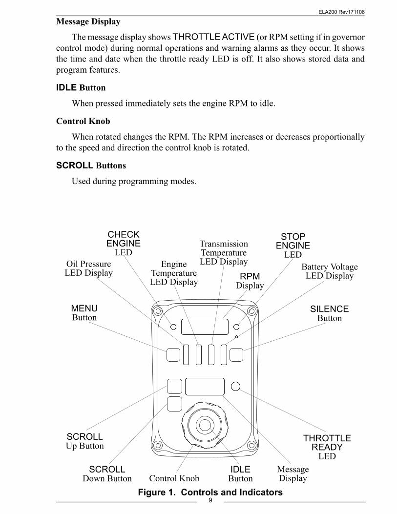
Controls and IndicatorsAll controls and indicators are located on the front of the control module. (Refer to
Figure 1.) The displays and LEDs are automatically adjusted for day or night operation. See Operation and Programming Sections for more information.
MENU Button
Used to access stored data and program features.
Oil Pressure LED Display
Shows engine oil pressure. The LEDs are green when the pressure is within normal limits and red when it is not.
CHECK ENGINE LED, STOP ENGINE LED
Repeats the warnings from the cab.
Engine Temperature LED Display
Shows engine coolant temperature. The LEDs are green when the temperature is within normal limits and red when it is not.
Transmission Temperature LED Display
Shows transmission temperature. The LEDs are green when the temperature is within normal limits and red when it is not.
RPM Display
Shows the current engine RPM in bright red digits. It also shows error codes, stored data, and program features.
Battery Voltage LED Display
Shows battery voltage. The LEDs are green when the voltage is within normal limits and red when it is not.
SILENCE Button
Press to suppress audio alarms. Used during programming modes.
THROTTLE READY LED
This LED is on when the required interlock conditions are met to begin operations.
ELA200 Rev171106
9Figure 1. Controls and Indicators
Message Display
The message display shows THROTTLE ACTIVE (or RPM setting if in governor control mode) during normal operations and warning alarms as they occur. It shows the time and date when the throttle ready LED is off. It also shows stored data and program features.
IDLE Button
When pressed immediately sets the engine RPM to idle.
Control Knob
When rotated changes the RPM. The RPM increases or decreases proportionally to the speed and direction the control knob is rotated.
SCROLL Buttons
Used during programming modes.
RPM Display
Message Display
Oil Pressure LED Display
Engine Temperature LED Display
Transmission Temperature LED Display
SILENCE Button
MENU Button
Battery VoltageLED Display
Control KnobIDLE Button
THROTTLE READY
LED
SCROLLUp Button
SCROLLDown Button
STOP ENGINE
LED
CHECK ENGINE
LED

ELA200 Rev171106
10
INSTALLATION
Install Control Module1. Measure and mark mounting location for control module panel cutout and
mounting screw holes. Make sure there is clearance behind the panel for the module and cables before cutting holes. Refer to Figure 2 for layout and dimensions.
2. Cut out a 3 1/2 by 5 3/4 inch hole.
3. Drill four holes, clearance or tapped, for 10-32 mounting screws.
4. Place control module in position and secure with screws.
5. Connect cables at rear of the control module. (Refer to Wiring Section.)
Install Engine SensorsFor most engines, the engine throttle display receives engine RPM, oil pressure,
engine coolant temperature, and transmission temperature data over the J1939 databus. Some engines do not broadcast this data over the databus and sensors may need to be installed.
Note: The ThrottleXcel may need a programming change for some sensor inputs to be recognized. If the sensor was not ordered as part of the ThrottleXcel kit you may need to contact FRC technical support for programming information.
The sensors are wired to the 12-pin connector at the rear of the control module. Refer to the Wiring Section.
Install BuzzerPin 6 on the 12-pin connector at the rear of the control module is provided to
connect an optional buzzer. Connect the ground side of the buzzer to pin 6. Maximum current through pin 6 is 300 mA. The buzzer ordered from FRC requires a 1-1/8 inch diameter mounting hole. (Refer to the Wiring section.)
Install High Idle KitThe high idle is activated when + VDC is provided to pin 7 (High Idle Active
Input) of the 12-pin connector and pin 6 (Interlock Input) of the 8-pin connector. Refer to High Idle Wiring.
Note: It is important that the connection to the Interlock Input from the High Idle circuit be isolated from the apparatus interlock wiring with the two diodes. The pump must NOT be engaged when using the high idle function and the THROTTLE READY LED will be off.

ELA200 Rev171106
11Figure 2. Control Module Mounting Dimensions
4 5/8"
6 3/4"
Mounting holes are clearance or tapped for 10-32 screws.
3 1/2"
5 3/4"
Panel Cutout 5 3/4"
4"
Maximum Radius
1/2"
1 1/2"
1 3/4"
2 1/2"4"

ELA200 Rev171106
12
OPERATIONThe ELA200 models are programmed to operate in one of the following control
modes dependent on requirements, engine type, and wiring.
Throttle Control ModeThis is the factory default. In this mode the ThrottleXcel is a traditional remote
engine hand throttle and provides manual control of the engine RPM. Set the control knob for a specific RPM, as the engine load changes the engine RPM may change. Changes in the ThrottleXcel output to adjust the engine RPM are made manually by turning the control knob.
The message display shows THROTTLE ACTIVE.
Governor Control ModeThis mode is programmed at installation. In this mode the ThrottleXcel is an engine
governor and maintains a constant engine RPM. It eliminates the need to make throttle adjustments as the engine load changes. Set the control knob for a specific RPM, as the engine load varies the engine RPM remains the same. Changes in the ThrottleXcel output to adjust the engine RPM are made automatically and hold engine speed at the RPM setting. (Changes to the RPM setting are made by turning the control knob.)
The message display shows the RPM setting in the form: RPM 1100.
Power-upNote: When power is applied to the ThrottleXcel the message display shows
the Software Program Revision Number for five (5) seconds and then the Control Mode for two (2) seconds.
On power-up the RPM display shows engine RPM, the four LED bar graphs are green indicating readings within normal ranges, and the message display alternates between showing the date and time.
If a monitored function is not within normal parameters the display flashes, the RPM display shows an error or fault warning code and a description shows in the message display. (Refer to Table 1. Error Codes or Table 2. Fault Warning Codes.)
If one of the inputs displayed by the LED bar graphs is not within normal range the LEDs will be red.
When all necessary throttle enables are active and the interlock circuit is complete, the THROTTLE READY LED comes on and the remote throttle is ready to control the engine RPM. The control signal is set at idle regardless of the control knob position.
RPM adjustments are made in both modes by turning the control knob. The engine can be brought down to idle quickly after operation with the touch of the red idle button.

ELA200 Rev171106
13
Table 2. Fault Warning CodesRPM
DisplayMessage Display Description Factory
Default SettingF01 HI BATT VOLTAGE High Battery Voltage 15.5 VF02 LOW BATT VOLTAGE Low Battery Voltage 11.8 V*F03 HI TRANS TEMP High Transmission Temperature 300 °FF04 LOW OIL PRESSURE Low Engine Oil Pressure 8 PSI**F07 HI ENG TEMP High Engine Coolant Temperature 220 °F**F09 ENG NOT RESPOND Engine Does Not Respond
* 11.8 engine running, 11.7 engine off.
Table 1. Error CodesRPM
DisplayMessage Display
Probable CauseNote: Not all inputs are used for all engines. For systems that use a datalink to pass information the datalink cable and connectors or ECM programming would be the probable cause.
E01 NO DATA >Datalink cable not connected / connected to wrong port>Broken wire / bad connector contact on datalink cable
E02 NO RPM Engine RPM not detected>Datalink cable not connected / connected to wrong port>Engine not running / ignition key on>Broken wire / bad connector contact on alternator cable
E04 NO OIL SENSOR
No Engine Oil Pressure Data Detected (w/separate sensor input)>Sensor cable not connected>Broken wire / bad connector contact on sensor cable>Defective pressure sensor
E07 NO ENG T SENSOR
No Coolant Temperature Data Detected (w/separate sensor input)>Sensor cable not connected>Broken wire / bad connector contact on sensor cable>Defective temperature sensor
E16 NO FRC DATALINK
>FRC datalink cable not connected / connected to wrong port>Broken wire / bad connector contact on cable
ControlsControl Knob
The control knob is used to adjust the engine RPM (or RPM setting). The ThrottleXcel senses how fast and in what direction the control knob is rotated and sends a signal to the ECM to increase or decrease the engine RPM proportionally.
If the control knob is rotated quickly; the engine RPM changes quickly.
If the control knob is rotated slowly; the engine RPM changes slowly.
• Rotate the control knob clockwise to increase engine RPM.
• Rotate the control knob counterclockwise to decrease engine RPM.
• Press the red IDLE button to immediately return the engine to idle.
** J1939 compliant—engine ECM will issue this warning.

ELA200 Rev171106
14
Detailed InformationThe four LED bar graphs provide constant display of safe operating ranges for
engine oil pressure, engine coolant temperature, transmission temperature, and battery voltage. They do not show exact numbers or units of measure. This detailed information is shown in the message display when the MENU button is pressed. Engine hours are also shown.
Show Detailed Information
Note: Detailed information is a display only mode and no changes can be made to the data.
The MENU button allows the operator to gain access to detailed information. Each time the MENU button is pressed the display scrolls to show the next value.
The message display indicates the following:
ENG TEMP ### °F (programmable for °C)
ENG OIL ### PSI (programmable for kPa or Bar)
BATT VDC ##.# V (programmable for 12V or 24V)
ENG HRS ####
TRANS T. ### °F (programmable for °C)The message display reverts to normal operation after 20 seconds if no buttons are
pressed. When a button other than the MENU button is pressed, the display immediately reverts to normal operation. The SILENCE button should be used during operations.

ELA200 Rev171106
15
High-IdleThe throttle programming includes a high-idle function. To activate the high-idle set
all interlocks as called for by local SOP (normally this would include the transmission in neutral and the parking brake on). Set the High-Idle switch to ON.
Note: The pump must NOT be engaged when using the high-idle function and the THROTTLE READY LED will be off.
Change High-Idle Setting
Note: The high-idle is set at about 1000 RPM at the factory. (This value varies depending on the specific engine.)
1. With the engine running, set the high-idle switch to ON.
Result: Engine goes to High-Idle RPM.
2. Press and hold IDLE button for 3 seconds.
Result: RPM display flashes and shows the high-idle setting.
3. Keep pressing the IDLE button and rotate control knob to desired RPM.
4. Release IDLE button to store the new high idle setting.
ELA200 Rev171106
16
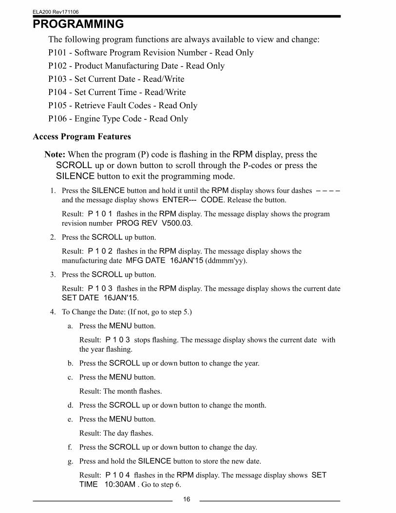
PROGRAMMINGThe following program functions are always available to view and change:P101 - Software Program Revision Number - Read OnlyP102 - Product Manufacturing Date - Read OnlyP103 - Set Current Date - Read/WriteP104 - Set Current Time - Read/WriteP105 - Retrieve Fault Codes - Read OnlyP106 - Engine Type Code - Read Only
Access Program Features
Note: When the program (P) code is flashing in the RPM display, press the SCROLL up or down button to scroll through the P-codes or press the SILENCE button to exit the programming mode.
1. Press the SILENCE button and hold it until the RPM display shows four dashes – – – – and the message display shows ENTER--- CODE. Release the button.
Result: P 1 0 1 flashes in the RPM display. The message display shows the program revision number PROG REV V500.03.
2. Press the SCROLL up button.
Result: P 1 0 2 flashes in the RPM display. The message display shows the manufacturing date MFG DATE 16JAN'15 (ddmmm'yy).
3. Press the SCROLL up button.
Result: P 1 0 3 flashes in the RPM display. The message display shows the current date SET DATE 16JAN'15.
4. To Change the Date: (If not, go to step 5.)
a. Press the MENU button.
Result: P 1 0 3 stops flashing. The message display shows the current date with the year flashing.
b. Press the SCROLL up or down button to change the year.
c. Press the MENU button.
Result: The month flashes.
d. Press the SCROLL up or down button to change the month.
e. Press the MENU button.
Result: The day flashes.
f. Press the SCROLL up or down button to change the day.
g. Press and hold the SILENCE button to store the new date.
Result: P 1 0 4 flashes in the RPM display. The message display shows SET TIME 10:30AM . Go to step 6.

ELA200 Rev171106
17
5. Press the SCROLL up button.
Result: P 1 0 4 flashes in the RPM display. The message display shows SET TIME 10:30AM .
6. To Change the Time: (If not, go to step 7.)
a. Press the MENU button.
Result: P 1 0 4 stops flashing. The message display shows the current time with the AM or PM flashing.
b. Press the SCROLL up or down button to change AM or PM.
c. Press the MENU button.
Result: The minute flashes.
d. Press the SCROLL up or down button to change the minutes.
e. Press the MENU button.
Result: The hour flashes.
f. Press the SCROLL up or down button to change the hours.
g. Press and hold the SILENCE button to store new time.
Result: P 1 0 5 flashes in the RPM display. The message display shows NO WARNING or LOGGED DATA. Go to step 8.
7. Press the SCROLL up button.
Result: P 1 0 5 flashes in the RPM display. The message display shows NO WARNING or LOGGED DATA.
8. Press the MENU button when it shows LOGGED DATA or go to step 9.
Result: 5 1 flashes in the RPM display. The fault, date, and time that the fault code was recorded shows in the message display.
a. To scroll through the logged fault code data, press the SCROLL up or down button.
b. Press the SILENCE button to exit viewing logged data.
9. Press the SCROLL up or down button.
Result: P 1 0 6 flashes in the RPM display. The message display shows the engine type code that is set in the program. (Refer to the Engine Code Reference Table.)
10. Press the SCROLL up or down button to scroll through the P-codes or press the SILENCE button to exit the programming mode.

ELA200 Rev171106
18
Access Password Protected ProgramsThe following program functions are available to view and change after the
password code has been entered:
Calibration Password Code 1111
C3 - Engine RPM CalibrationRefer to Calibration Section.
Enter Password Code
Note: To exit the programming mode, press the SILENCE button when the program code flashes in the RPM display.
1. Press the SILENCE button and hold it until the RPM display shows four dashes – – – – and the message display shows ENTER--- CODE. Release the button.
2. Press the MENU button within three seconds. The message display shows CODE ENTRY. The RPM display shows the number 1000. Each time the MENU button is pressed the first digit increments by 1. Set the first digit to the desired number.
3. Press the SILENCE button to move the curser to the next digit. Press the MENU button to change the digit.
4. Repeat step 3 and enter the password code. (Calibration password is 1111.)
Result: When a correct password code is entered C 3 for calibration or P 3 x x flashes in the RPM display.
5. Press the SCROLL up or down button when the program code is flashing to scroll through the program codes.
6. Press the MENU button to enter the programming mode to view and change parameter settings.
Result: The program code stops flashing. The message display shows a selectable option or a numerical value.
7. Press the MENU button to change a selectable option or the SCROLL up or down button to change a numerical value.
8. Press the SILENCE button to save the changes and exit the programming mode.
Result: The program code advances to the next code and flashes.
9. Repeat steps 5 through 8 as necessary.
10. Press the SILENCE button when the program code is flashing to exit.

ELA200 Rev171106
19
This page intentionally left blank.

ELA200 Rev171106
20
CODE DESCRIPTION MESSAGE DISPLAY
Press MENU Button Again
Press MENU Button Again
C3 Engine RPM Calibration CAL.ENG RPM
SET RPMXXXX
Table 3. Calibration Codes Quick Reference Chart
CALIBRATIONThree programs are available after the calibration password code has been entered:C3 - Engine RPM CalibrationRefer to Table 5. Calibration Codes Quick Reference Chart.
Enter Calibration Password Code 1111
Note: To exit the programming mode, press the SILENCE button when the program code flashes in the RPM display.
1. Enter the password code 1111. (Refer to Programming Section.)
Result: When the correct password code is entered C 3 flashes in the RPM display. The message display shows CAL. ENG RPM.
2. Press the SCROLL up or down buttons when the program (C) code is flashing to scroll through the program codes.
Refer to specific calibration section for detailed procedures.
Note: If there is a failure during calibration the message display shows SENSOR PROBLEM.
3. Press the SILENCE button when the program (C) code is flashing to exit.

ELA200 Rev171106
21
Engine RPM (Code C3)This code is not applicable for engines with the J1939 CAN connected. To perform
the following calibration, a reference tachometer is needed to verify the correct engine RPM.
1. Apply power to the display module.
2. Enter the calibration password.
3. Scroll to code C3 CAL. ENG RPM.
4. Press the MENU button to show SET RPM.
Result: Flashing digit is ready to be changed.
5. Set the RPM to match the reference RPM. Press the SCROLL up or down buttons to change the value. Press the MENU button to change the digit.
6. Press the SILENCE button to save the setting into memory.
7. Press the SILENCE button when the program (C) code is flashing to exit calibration. Press the MENU button to enter the next program. Press the SCROLL up or down buttons to scroll through program codes.

ELA200 Rev171106
22
Notes:- Not all wires are used for all engines.- For 2011 6.7L engines and newer, the J1939 Translator Module needs to be installed.- High idle is not available for Ford or Mack.- When using an FRC provided engine sensor cable, the red wire is sensor signal and the black wire connects to a ground.
Figure 3. Connectors
WIRINGThe following figures include the schematics, wiring diagrams, block diagrams,
and cables for the ThrottleXcel.
Connectors and CablesFor most engines the throttle display receives engine RPM, oil pressure, and
coolant temperature data over the J1939 data link from the ECM. Some engines do not broadcast this data over the data link and sensors may need to be installed.
When the GOVERNOR CONTROL MODE is programmed with Cummins, Detroit Diesel, and Mercedes engines, the governor is designed to control engine throttle directly over the SAE J1939 databus. Remote throttle does not need to be enabled in the ECM and remote throttle wiring is not needed.
NOTE: Not all wires are used for all engines. Refer to the engine specific wiring diagram for interface connections.
8 Pin Connector/CablePin Wire Color Description 1 Red Supply Voltage (12/24 VDC)2 Black Ground3 Orange +5 VDC Reference From ECM4 White Throttle Signal To ECM 5 Green Signal Return From ECM6 Yellow Interlock Input (+ VDC)7 Blue Throttle Enable Signal Output8 Brown Foot Pedal Signal Input
Control Module Rear View
8-Pin Connector
Pin 1
12-Pin Connector
Pin 1
6-Pin Connector
Pin 1
USBAccess Port*
Vent
12 Pin Connector/CablePin Wire Color Description 1 NC2 NC3 NC4 Blue Engine Oil Press. Sensor Signal5 Orange Engine Temp. Sensor Signal6 Brown Buzzer Ground (300mA)7 Violet High Idle Active Input (+ VDC)8 White J1939 CAN (Shield)9 Black J1939 CAN (–)10 Red J1939 CAN (+)11 Green Transmission Temp. Sensor Signal12 Yellow RPM Signal
*NOTE: If opened, USB access port plug must be tightened to a torque of 8-10 in-lbs. Exceeding this torque value can result in damage to its water seal capability. Warning: Flange may not fully bottom out.

ELA200 Rev171106
23Figure 4. Connector Wiring
6 Pin Connector/CablePin Wire Color Description 1 NC2 NC3 NC4 Green FRC Datalink (–)5 Yellow FRC Datalink (+)6 NC
12-Pin Connector
Note: The program code P303 must be set to REMOTE on the Secondary Controller control module.
To J1939(See Engine Specific Wiring)
Secondary Controller12, 8 and 6 Pin Connector Wiring
+12 VDC
GND
Ignition Key
RED
BLK
8-Pin Connector
NOTE: Terminating resistor and adapters are included in the kit for connection to the primary display; no other wires are required for remote operation.
6-Pin Connector
YELGRN
FRC Datalink (+)FRC Datalink (–)
To the Primary Controller
Data Bus Terminator
6-Pin Connector
YELGRN
FRC Datalink (+)FRC Datalink (–)
To the Secondary Controller
Data Bus Terminator
Secondary Controller, Cables and Connections

ELA200 Rev171106
24
Figure 5. Cummins ELA201 Wiring
8-Pin Connector(Refer to Figure 3)
J1939 Datalink (–)
J1939 Datalink (–)
Pin 9 Black Wire
Pin 9 Black Wire
Pin 10 Red Wire
Pin 10 Red Wire
J1939 Datalink (+)
J1939 Datalink (+)
12-Pin Connector (Refer to Figure 3)
12-Pin Connector (Refer to Figure 3)
Cummins Harness ConnectionsInterface Information
The ECM Remote Accelerator (Throttle) Option has to be set to ON. The diagnostic tool cannot be used to do this, an Insight service tool must be used. Refer to an authorized dealer to program this option.
DO NOT WIRE FOR GOVERNOR CONTROL MODE
DO NOT WIRE FOR GOVERNOR CONTROL MODE
2010CM570 Model Engine
+12 (24) VDC
Ignition KeyGND
+12 (24) VDC Pump Engaged
Interlock
1 RED
2 BLK
3 ORG
4 WHT
5 GRN
6 YEL
7 BLU
8 BRN
50-Pin OEM Connector
5256434037
1817
863616766
4622
48214943
3746
Sensor Supply 5VDCRemote Accelerator SignalRemote Accelerator Return
Remote Accelerator ON/OFF SwitchMax Speed/Governor Type Switch
Accelerator Supply (+)Remote Accel. Position
Accelerator Supply ReturnRemote Accel. Switch
2013CM2350 Model Engines
2010CM2250 ISC8.3 ISL9
Model Engines
CM2250 ECM OEM Connector
CM2350 96-Pin OEM Connector

ELA200 Rev171106
25Figure 6. Detroit Diesel ELA202 Wiring
Detroit Diesel Harness ConnectionsInterface Information
2007 and Newer EngineDDEC VI
Vehicle Interface Harness
DO NOT WIRE FOR GOVERNOR CONTROL MODE
Sensor Return
Sensor Supply (5 VDC)
Variable Speed Governor
ECM
Yel/Blk
Yel/Red
Ppl/Yel
V-11
V-14
V-60
8-Pin Connector(Refer to Figure 3)
+12 (24) VDC
Ignition KeyGND
+12 (24) VDC Pump Engaged
Interlock
21-PIN Connector #3
3/33/43/2
Sensor Supply
Remote PTO
Sensor Return
Remote Throttle Select Switch
Remote PTO Switch2/82/9
18-PIN Connector #2
1 RED
2 BLK
3 ORG
4 WHT
5 GRN
6 YEL
7 BLU
8 BRN
2006 and Older EngineDDEC V
Vehicle Interface Harness
DDEC V
12-Pin Connector (Refer to Figure 3)
Pin 9 Black Wire
Pin 10 Red Wire
Pin 8 White Wire
J1939 CAN (+)
SHIELD
J1939 CAN (–)
2/18
2/17
2/16
V-43
V-44
V-58
Dk Blu/Red
Dk Blu/Yel
Dk Blu
J1939 (+)
Shield
J1939 (–)
DDEC VI
18-PIN Connector #2
Vehicle Interface Harness
THROTTLE CONTROL MODE
ELA200 Rev171106
26Figure 7. Detroit Diesel ELA202 Wiring Governor Control Mode
Governor Control ModeThis wiring is for use ONLY when the ThrottleXcel is programmed for the
GOVERNOR CONTROL MODE.
DDEC V
12-Pin Connector (Refer to Figure 3)
Pin 9 Black Wire
Pin 10 Red Wire
Pin 8 White Wire
J1939 CAN (+)
SHIELD
J1939 CAN (–)
2/18
2/17
2/16
V-43
V-44
V-58
Dk Blu/Red
Dk Blu/Yel
Dk Blu
J1939 (+)
Shield
J1939 (–)
DDEC VI
18-PIN Connector #2
Vehicle Interface Harness

ELA200 Rev171106
27
Navistar Harness ConnectionsInterface Information
The ECM must be programmed for a remote throttle input. When using code or 12VXY, 12VZA, or 12VZB the following parameters need to be set:
PTO-REMOTE-PEDAL to 1-Yes; PTO-REM-PEDAL-RTZ to 1-RTZ-not;PTO-DISABLE-CAB-INTERFACE to 1-Yes; DRIVELINE-MODE to 1
Note: Check the engine code to verify the program setting (for J1939 control use 4C and for voltage control use 4D). Wire accordingly or change the code.
ESTConnector
J1939 CAN (–)Shield
J1939 CAN (+)
12-Pin Connector (Refer to Figure 3)
Figure 8. Navistar ELA204 Wiring
+12 (24) VDCIgnition Key
GND +12 (24) VDC Pump Engaged
Interlock8-Pin Connect(Refer to Figure 3 )
Voltage Ref 5V
REM Accelerator
Signal Return
Variable PTO Enable
Transfer Case
X1-27
X1-50
X1-35
X1-60
X1-11
ECM Function
12VZACircuit #
(V8)
K95
K97RPS
K95R
K97RVAR
K97SCX
12VZACircuit #
(I6)
K97FV
K99F
K97WA
K97CC
K97XC
X1-14
X1-20
X1-6
X3-20
X4-6
12VZBCircuit #(IBBE)
K92A4
K92A5
K92A3
K92A12
K92A7
Split Shaft Only
Pin 8 White WirePin 9 Black WirePin 10 Red Wire
Pin EPin DPin C
C1-47
C1-34
J1939 (–)
J1939 (+)Pin 9 Black Wire
Pin 10 Red Wire
12-Pin Connector (Refer to Figure 4)
ECM 58-PinC1 Connector
Note: Refer to Figure 4. Connector Wiring 8-Pin connector for power and interlock wire connections.
J1939 CAN Bus Control 12VXY2010 and Newer MAXXFORCE 11 and 13 Engines
Voltage ControlPost 2007 MAXXFORCE 7, DT, 9, 10, 11, and 13 Engines
Pin 1 Red Wire
Pin 2 Black Wire
Pin 6 Yellow Wire
Pin 3 Orange Wire
Pin 4 White Wire
Pin 5 Green Wire
Pin 7 Blue Wire
This wiring is for use ONLY when the ThrottleXcel is programmed for the GOVERNOR CONTROL MODE

ELA200 Rev171106
28Figure 9. Navistar/International Chassis ELA204 Wiring
Navistar / International Chassis Harness ConnectionsInterface Information
Note: This function is not available on custom chassis, refer to Figure 8. Navistar ELA Wiring.
Vehicles must be equipped with an Electronic System Controller (ESC) and have the Body Builder J1939 Datalink available.
Remote Engine Speed must be set to ON (Feature Code 0595AHA)Connect the Body Builder J1939 Datalink to the FRC Datalink for engine control
as shown below. This wiring is for use ONLY when the ThrottleXcel is programmed for the
GOVERNOR CONTROL MODE.
ATA Datalink
ConnectorJ1939 CAN (Shield)
J1939 CAN (–)
J1939 CAN (+)
Pin 8 White Wire
Pin 9 Black Wire
Pin 10 Red Wire
Pin E
Pin D
Pin C
12-Pin Connector (Refer to Figure 3)
Note: The Body Builder J1939 Datalink is for engine control, the J1939 CAN Bus provides
engine information to the governor.
Body Builder J1939 Datalink (–)
Body Builder J1939 Datalink (+)
FRC Datalink (–)
FRC Datalink (+)
F5
F6
6-Pin Connector (Refer to Figure 4)
1602(ESC J5)
Connector
Pin 4 Green Wire
Pin 5 Yellow Wire
Engine Control Output
Engine Information Input
1 RED
2 BLK
3 ORG
4 WHT
5 GRN
6 YEL
7 BLU
8 BRN
+12 (24) VDC
Ignition KeyGND
+12 (24) VDC Pump Engaged
Interlock
8-Pin Connector (Refer to Figure 3)

ELA200 Rev171106
29
70-Pin Vehicle Harness Connector
12-Pin Connector (Refer to Figure 3)
J1939 Datalink Negative (–)
J1939 Datalink Positive (+)
Pin 8 White Wire
Pin 9 Black Wire
Pin 10 Red Wire
+12 (24) VDCIgnition Key
GND
+12 (24) VDC Pump Engaged
Interlock
8-Pin Connector(Refer to Figure 3)
G845-PU
K999-GN
A249-BK
K990-GN
K900-YL
Input #1 PTO ON/OFF Switch
Input #8 (Remote Throttle PWM)68
56
42
34
50
ECM
1 RED
2 BLK
3 ORG
4 WHT
5 GRN
6 YEL
7 BLU
8 BRN
J1939 Datalink Shield
Caterpillar Harness ConnectionsInterface Information
The parameter settings for PTO Configuration are programmed to Remote Throttle or Remote Throttle with J1939 Speed Command.
ECM software with a Personality Module release date of May08 for C7, C9, C13, C15 engines, has the Remote Throttle with J1939 Speed Command setting available. This setting allows the engine speed to be controlled during PTO operations by a J1939 compliant device.
Refer to an authorized dealer to program one of these options.
C7, C9, C10, C11, C12, C13, C15 Engine Interface
Engines with 70-pin OEM connector.
Figure 10. Caterpillar ELA205 Wiring(Sheet 1 of 2)

ELA200 Rev171106
30
1 RED
2 BLK
3 ORG
4 WHT
5 GRN
6 YEL
7 BLU
8 BRN
Figure 10. Caterpillar ELA205 Wiring(Sheet 2 of 2)
+12 (24) VDC
Ignition KeyGND
+12 (24) VDC Pump Engaged
Interlock
8-Pin Connector (Refer to Figure 3)
K999-GN
K982-YL
Multi-Function Input #1 PTO ON/OFF Switch
Multi-Function Input #3 Remote Throttle PWM
40-Pin Vehicle Harness Connector
31
8
ECM
C10, C12 Engine Interface
Engines with 40-Pin OEM connector.
Note: Refer to 12-Pin connector Figure 3 for separate sensor and RPM connections.

ELA200 Rev171106
31
Ford Harness Connections2011 Model F-250/350/450/550 - 6.7L Diesel Engines
J1939 Interface Information
A J1939 CAN input is required to provide engine information to the ThrottleXcel. The Ford vehicle CAN Bus information needs to be interpreted. A J1939 Translator Module with a harness to connect it to the ODB-II connector must be installed.
Note: The ODB-II connector and wiring is accessed under the dash.There are two scenarios:
I. The J1939 Translator Module is installed as a component with governor kit (no Seat Belt Monitoring System is installed).
Install the J1939 Translator Module and the ODB-II interconnecting harness (provided with the throttle kit). A 2-Pin connector is provided for the wires to ThrottleXcel.
II. The J1939 Translator Module is installed as part of the NFPA1901 compliant Seat Belt Monitoring and VDR System.
The Translator Module/ODB-II/VDR harness is under the driver side dash. A T-cable (provided with the governor kit) needs to be installed at the 4-Pin connector that is between the harness and the VDR.
Stationary Elevated Idle Control (SEIC) Interface Information
Note: Access wires for SEIC are located in cabin, tagged and bundled above the parking brake pedal assembly behind datalink connector.
SEIC is used in two modes: stationary and split shaft. The ThrottleXcel provides a variable RPM control to the Ford Power train Control Module (PCM) when all enabling conditions are met. Refer to Figure 13 Ford 6.7L ELA PCM Wiring.
SEIC Enablers: Parking brake applied; Foot off of service brake; Vehicle in park; Foot off of accelerator pedal; Vehicle speed is 0 mph (stationary); Engine at a stable base idle speed.
Note: Do not press the accelerator or service brake pedal when engaging the fire pump, this prevents the switch into SEIC.

ELA200 Rev171106
32Figure 11. Ford 6.7L ELA206 J1939 Translator Module Wiring
Translator Module Harness
(2-Pin Connector)
J1939 (+)
J1939 (–)Pin 10 Red Wire
Pin 9 Black Wire
ELA 12-Pin
Connector (Refer to Figure 3)
Mounting holes are clearance for #8 screws.
Install the J1939 Translator Module with the ODB-II Interconnecting Harness or Install the T-cable between 4-Pin connectors.
To install the J1939 Translator Module with ODB-II harness, read and follow the installation instructions provided with the Translator Module kit.
J1939 Translator Module
2"
4"3 1/2"
1"
J1 Connector
TEST Pad
Disconnect VDR harness 4-Pin connector and connect the T-cable
provided with the governor kit.
J1939 Translator Module and VDR Harness
To OEM ODB-II
Connector
Pass Through ODB-II
Connector
To Translator Module J1 Connector
To FRC VDR 8-Pin Connector
2-Pin Connector1-Red J1939 (+)2-Blk J1939 (–)
4-Pin VDR Connector
To ThrottleXcel12-Pin Connector
Note: The TEST pad on the module circuit board has to be held at ground when the harness connector is plugged into the J1 connector.
To OEM ODB-II
Connector
To Translator Module J1 Connector
Pass Through ODB-II
Connector
2-Pin Connector1-Red J1939 (+)2-Blk J1939 (–)
To ThrottleXcel12-Pin Connector
J1939 Translator Module Harness
Translator Module Harness to Governor
Note: Refer to Figure 3. Connector Wiring for ThrottleXcel power and interlock wire connections.

ELA200 Rev171106
33Figure 12. Ford 6.7L ELA206 PCM Wiring
2011 Model F-250/350/450/550 - 6.7L Diesel EngineStationary Elevated Idle Control (SEIC)
Note: Do not press the accelerator or service brake pedal when engaging the fire pump, this prevents the switch into SEIC.
8-Pin Connector (Refer to Figure 3)
PCM
PTO REF
PTO RTN
PTO RPM
PTO RS1
Circuit #Wire Color
LE434White/Brown
RE327Gray/Violet
CE914Green
CE912Yellow/Green
Pin 3 Orange Wire
Pin 5 Green Wire
Pin 4 White Wire
55
22
8
6+12 (24) VDCPump in Gear
C1232B-Stationary Mode
Access wires for SEIC are located in cabin, tagged and bundled above the parking brake pedal assembly behind datalink connector.
Split Shaft Mode PCM
PTO REF
PTO RTN
PTO RPM
PTO RS1
PTO RS2
Circuit #Wire Color
LE434White/Brown
RE327Gray/Violet
CE914Green
CE912Yellow/Green
CE933Blue/Orange
Pin 3 Orange Wire
Pin 5 Green Wire
Pin 4 White Wire
55
22
8
6
4
+12 (24) VDCPump in Gear
C1232B-
8-Pin Connector (Refer to Figure 3)
Note: Refer to Figure 3. Connector Wiring for power and interlock wire connections.
Split Shaft Mode is activated by applying supply voltage to both the PTORS1 and PTORS2 PCM circuits simultaneously.1. Assure engine is running and fully warmed-up.2. Apply parking brake.3. Transmission in neutral to disengage drive wheels.4. With foot off brake and accelerator, switch Split-Shaft PTO on.5A. *Only for MY 2011-2012: Without pressing the brake, shift transmission into drive. If vehicle unexpectedly lurches or moves, immediately press brake pedal and shift transmission into park or neutral to secure vehicle.5B. *Only for MY 2013: While pressing the service brake, shift transmission into drive.6. Engage PTO load.
NOTE: *Refer to Ford SVE Bulletin Q-180R4Once the system enablers are met voltage may be added to the SEIC system for activation.If power is applied prior to the enablers being met, a system error may occur, and the SEIC system
will have to be reset.If an SEIC disabler occurs the engine requires a change-of-state, meaning the operator is required to
turn off voltage to the PTO-Request circuit, and back on again to re-invoke SEIC and PTO operation.

ELA200 Rev171106
34
Mack Harness ConnectionsInterface Information
The 8-Pin cable needs to be wired to the cab foot throttle harness. Use a voltmeter to determine which pins are 5 V Reference and Engine Control Signal.
The engine control signal will be 0.7 volts at idle and rise to approximately 3.8 volts as the foot pedal is pressed.
Note: Refer to 12-Pin connector Figure 3 for separate sensor and RPM connections.
Figure 13. Mack ELA207 Wiring
8-Pin Connector(Refer to Figure 3)
Cab Foot Throttle
Cab Foot Throttle
Connector
+12 (24) VDC
Ignition KeyGND
+12 (24) VDC Pump Engaged
Interlock
To Engine VECU
Throttle Pedal
Analog Ground
Throttle Pedal Supply
Note: Use a plug and receptacle on the Engine Control Signal wire so the ends can be reconnected if the ThrottleXcel is removed.
NC
NOC
Relay
+12 VDC
IVSOutput Supply
IVSOutput Supply
Throttle Pedal
Throttle Pedal SupplyAnalog Ground
V-MAC IV with IVS switch in
the foot throttle.
A23B19
B8
1 RED
2 BLK
3 ORG
4 WHT
5 GRN
6 YEL
7 BLU
8 BRN

ELA200 Rev171106
35Figure 14. Mack ELA207 Wiring Governor Control Mode
Governor Control ModeThis wiring is for use ONLY when the ThrottleXcel is programmed for the
GOVERNOR CONTROL MODE.For V-MACK IV 07 and newer, the governor is designed to control engine throttle
directly over the SAE J1939 databus.
J1939 CAN Bus Control
VC5
VC4
J1939 (–)
J1939 (+)Pin 9 Black Wire
Pin 10 Red Wire
12-Pin Connector (Refer to Figure 3)
VECUConnector C

ELA200 Rev171106
36
Scania Harness Connections—Type AInterface Information
For use on P, R, and T-series trucks equipped with a bodywork control unit (BWS). Connector C259 is available on all vehicles ordered with any of the bodywork options. It is located on the plate for the electrical bodywork interface for body builders. Connector C259 is white and has 21 pins. (February 2005 to 2015.)
Figure 15. Scania ELA208 Wiring—Type A
12
15
18
2
1
Contact Housing (MCP)
C259
3
6
9
The EXT switch must be in the ON position when
operating the throttle.
12-Pin Connector (Refer to Figure 3)
8-Pin Connector (Refer to Figure 3)
C259 Connector
8Engine RPM Control 2 +24 Volts
J1939 CAN high 21
9 Engine RPM Control 2 Earth
11
10 Engine RPM Control 2 Signal
Engine RPM Control 2 +5 Volts
J1939 CAN low 20
Note: Signal to pin 10 is 0.6 to 3.0 V
Pin 9 Black WirePin 10 Red Wire
Pin 4 White Wire
Pin 5 GreenWire
Pin 3 Orange Wire
Pin 7 Blue Wire
ELA200 Rev171106
37
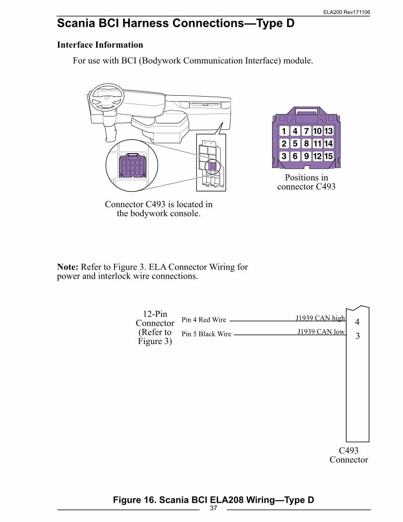
Scania BCI Harness Connections—Type DInterface Information
For use with BCI (Bodywork Communication Interface) module.
Figure 16. Scania BCI ELA208 Wiring—Type D
Note: Refer to Figure 3. ELA Connector Wiring for power and interlock wire connections.
Connector C493 is located in the bodywork console.
Positions in connector C493
12-Pin Connector (Refer to Figure 3)
J1939 CAN high 4J1939 CAN low 3
Pin 4 Red Wire
Pin 5 Black Wire
C493Connector

ELA200 Rev171106
38
Mercedes Harness ConnectionsInterface Information.
Figure 17. Mercedes ELA210 Wiring
VCU
12-Pin Connector (Refer to Figure 3) Pin 10 Red Wire
Pin 9 Black WirePin 8 White Wire
Remote PTO Power Supply
Remote Throttle Signal Analog
VCU 18-Pin Connector
18
17
Sensor Ground (Throttle Pedal & Remote)
VCU 21-Pin Connector
14
2006 and Older Connectors
7 Remote Accel Select Sw
10 Remote PTO Sw
20 Shield21 – J193919 + J1939
1 RED
2 BLK
3 ORG
4 WHT
5 GRN
6 YEL
7 BLU
8 BRN
8-Pin Connector(Refer to Figure 3 )
+12 (24) VDC
Ignition KeyGND
+12 (24) VDC Pump Engaged
Interlock
2007 and Newer EngineDDEC VI
Vehicle Interface Harness 21-PIN Connector #3
3/33/43/2
Sensor Supply
Remote PTO
Sensor Return
Remote Throttle Select Switch
Remote PTO Switch2/82/9
18-PIN Connector #2
Pin 8 White Wire
DDEC VIVehicle Interface Harness
18-PIN Connector #212-Pin
Connector (Refer to Figure 3)
J1939 CAN (+)
SHIELD
J1939 CAN (–)
2/18
Pin 9 Black Wire2/172/16
Pin 10 Red Wire
DO NOT WIRE FOR GOVERNOR CONTROL MODE

ELA200 Rev171106
39
J1939 CAN Bus Control
U
V
J1939 (–)
J1939 (+)Pin 9 Black Wire
Pin 10 Red Wire
12-Pin Connector (Refer to Figure 3)
Figure 18. John Deere ELA216 Wiring
John Deere Harness ConnectionsInterface Information
CAN Controller will request a torque by means of TSC1. This option is disabled by default and is selectable in the Trim Options page for this application. Source address 57 should be programmed.
Note: Refer to Figure 3 Connector Wiring for Power and Interlock wire connections.
Circuit No. 905 Green
Circuit No. 904 Yellow
21 Pin Deutsch Connector
TIER-3PowerTech Engines
ELA200 Rev171106
40
J1939 CAN Bus Control
X1997/18
X1997/17
J1939 (–)
J1939 (+)Pin 9 Black Wire
Pin 10 Red Wire
12-Pin Connector (Refer to Figure 3)
18-Pin Connector X1997
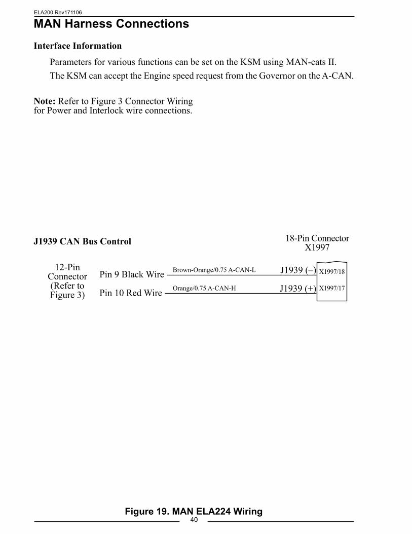
Figure 19. MAN ELA224 Wiring
MAN Harness ConnectionsInterface Information
Parameters for various functions can be set on the KSM using MAN-cats II.The KSM can accept the Engine speed request from the Governor on the A-CAN.
Note: Refer to Figure 3 Connector Wiring for Power and Interlock wire connections.
Brown-Orange/0.75 A-CAN-L
Orange/0.75 A-CAN-H
ELA200 Rev171106
41
CAN Bus Control
4
6
(–)
(+)Pin 9 Black Wire
Pin 10 Red Wire
12-Pin Connector (Refer to Figure 3)
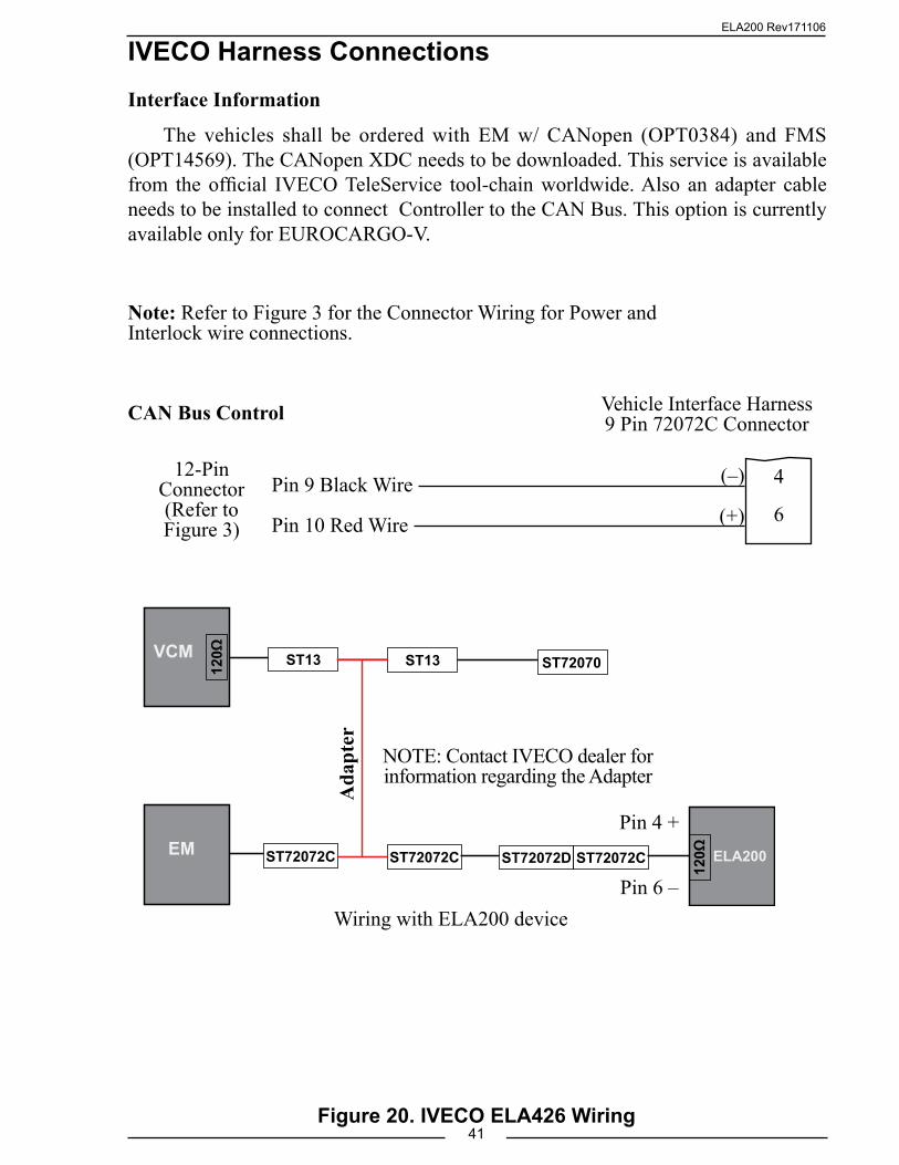
IVECO Harness ConnectionsInterface Information
The vehicles shall be ordered with EM w/ CANopen (OPT0384) and FMS (OPT14569). The CANopen XDC needs to be downloaded. This service is available from the official IVECO TeleService tool-chain worldwide. Also an adapter cable needs to be installed to connect Controller to the CAN Bus. This option is currently available only for EUROCARGO-V.
Note: Refer to Figure 3 for the Connector Wiring for Power and Interlock wire connections.
Wiring with ELA200 device
VCM
EM
120Ω
ELA200
120Ω
ST13
ST72072C ST72072C ST72072CST72072D
ST72070ST13
Vehicle Interface Harness9 Pin 72072C Connector
Pin 4 +
Pin 6 –
Ada
pter
NOTE: Contact IVECO dealer for information regarding the Adapter
Figure 20. IVECO ELA426 Wiring

ELA200 Rev171106
42Figure 21. High-Idle Wiring
High-Idle WiringThe throttle programming includes a high-idle function. To activate the high-idle
provide + VDC to pin 7 (High-Idle Active Input) of the 12-pin connector and pin 6 (Interlock Input) of the 8-pin connector. The high-idle connection to pin 6 must be isolated form the interlock circuit using two diodes (see schematic).
Note: It is important that the connection to the Interlock Input from the High-Idle circuit be isolated from the apparatus interlock wiring with the two diodes. Refer to the wiring diagram. The pump must NOT be engaged when using the high idle function.
The high-idle is set at about 1000 RPM at the factory. (This value will vary depending on the specific engine.) To adjust this setting refer to High-Idle in the Operation Section.
A High-Idle Kit is available from FRC.Includes:ON/OFF SwitchIndicator LightTwo Diodes
To 8-Pin ConnectorPin 6 Yellow Wire
Interlock Input
To 12-Pin ConnectorPin 7 Violet Wire
High-Idle Active Input
High-Idle ON/OFF Switch
Diodes(IN4002 or equivalent)
From Transmission
Neutral+ VDC
Pump Engaged Indicator
Light
NC
NOC
ON
OFF
High-Idle Indicator
LightGND
FromPump
Engaged +12 VDC
GND
NC
NO
C
From Parking BrakeGND
NC
NO
C
ELA200 Rev171106
43
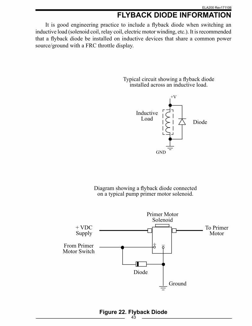
FLYBACK DIODE INFORMATIONIt is good engineering practice to include a flyback diode when switching an
inductive load (solenoid coil, relay coil, electric motor winding, etc.). It is recommended that a flyback diode be installed on inductive devices that share a common power source/ground with a FRC throttle display.
Figure 22. Flyback Diode
Typical circuit showing a flyback diode installed across an inductive load.
Diagram showing a flyback diode connected on a typical pump primer motor solenoid.
Primer Motor Solenoid
+ VDC Supply
From Primer Motor Switch
To Primer Motor
Ground
+ –
Diode
Diode Inductive
Load
GND
+V

ELA200 Rev171106
44