engine mechanical overhaul - madstyle1972madstyle1972.com/repair/14/20jb4c04/w040001.pdf · a01160...
TRANSCRIPT

140Q9–03
A64807
A01155
A01156
A65712
SST
–ENGINE MECHANICAL CYLINDER BLOCK (1ZZ–FE)14–151
1416Author�: Date�:
2003 COROLLA MATRIX 218W (RM940U)
OVERHAUL
1. REMOVE CYLINDER BLOCK WATER DRAIN COCKSUB–ASSY
(a) Remove the cylinder block water drain cock from the cyl-inder block.
2. INSPECT CONNECTING ROD THRUST CLEARANCE(a) Using a dial indicator, measure the thrust clearance while
moving the connecting rod back and forth.Standard thrust clearance:0.160 – 0.342 mm (0.063 – 0.0135 in.) Maximum thrust clearance: 0.342 mm (0.0135 in.)
If the thrust clearance is greater than maximum, replace theconnecting rod.If necessary, replace the crankshaft.3. INSPECT CONNECTING ROD OIL CLEARANCENOTICE:Do not turn the crankshaft.(a) Using marking paint, write the matched cylinder number
on each connecting rod and cap.HINT:The match marks on the connecting rods and caps are for en-suring correct reassembly.
(b) Using SST, remove the 2 bolts and connecting rod cap.SST 09205–16010
(c) Clean the crank pin and bearing.(d) Check the crank pin and bearing for pitting and scratches.

A01159
Plastigage
A65713
Front Mark
A65714
SST
A65715
Paint Mark
90�Engine Front
A65712
SST
14–152–ENGINE MECHANICAL CYLINDER BLOCK (1ZZ–FE)
1417Author�: Date�:
2003 COROLLA MATRIX 218W (RM940U)
(e) Lay a strip of Plastigage across the crank pin.
(f) Check that the front mark of the connecting rod cap is fac-ing in the correct direction.
(g) Apply a light coat of engine oil on the threads and underthe heads of the connecting rod cap bolts.
(h) Using SST, tighten the bolts in several passes by the spe-cified torque.SST 09205–16010Torque: 20 N ⋅m (204 kgf ⋅cm, 15 ft ⋅lbf)
(i) Mark the front of the connecting cap bolts with paint.(j) Retighten the cap bolts by 90� as shown in the illustration.(k) Check that the crankshaft turns smoothly.
(l) Remove the 2 bolts and connecting rod cap.

A01160
A65716
Mark
A01166
A64813
–ENGINE MECHANICAL CYLINDER BLOCK (1ZZ–FE)14–153
1418Author�: Date�:
2003 COROLLA MATRIX 218W (RM940U)
(m) Measure the Plastigage at its widest point.Standard oil clearance:0.028 – 0.060 mm (0.0011 – 0.0024 in.) Maximum oil clearance: 0.080 mm (0.0032 in.)
NOTICE:Remove the Plastigage completely after the measurement.If the oil clearance is greater than maximum, replace the con-necting rod bearing.If necessary, grind or replace the crankshaft.HINT:If replacing a bearing, select a new one having the same num-ber as marked on the connecting rod. There are 3 sizes of stan-dard bearings, marked ”1”, ”2” and ”3” accordingly.
Item Mark mm (in.)
Connecting rod large endbore diameter
12
3
47.000 – 47.008 (1.85039 – 1.85071)47.009 – 47.016 (1.85075 – 1.85102)47.017 – 47.024 (1.85106 – 1.85134)
Connecting rod bearingthickness
12
3
1.486 – 1.490 (0.05850 – 0.05866)1.491 – 1.494 (0.05870 – 0.05882)1.495 – 1.498 (0.05886 – 0.05898)
Crankshaft pin outer diame-ter
– 43.992 – 44.000 (1.73197 – 1.73228)
4. REMOVE CONNECTING ROD SUB–ASSY(a) Using a ride reamer, remove all the carbon from the top
of the cylinder.
(b) Push the piston, connecting rod assembly and upperbearing through the top of the cylinder block.
HINT:� Keep the bearing, connecting rod and cap together.� Arrange the piston and connecting rod assemblies in the
correct order.

A64814
A64815
A01175
Piston RingExpander
A01192
A63898
14–154–ENGINE MECHANICAL CYLINDER BLOCK (1ZZ–FE)
1419Author�: Date�:
2003 COROLLA MATRIX 218W (RM940U)
5. REMOVE CONNECTING ROD BEARING(a) Remove the connecting rod bearing from the connecting
rod cap.
(b) Remove the connecting rod bearing from the connectingrod.
6. REMOVE PISTON RING SET(a) Using a piston ring expander, remove the 2 compression
rings.(b) Remove the 2 side rails and oil ring by hand.
7. REMOVE W/PIN PISTON SUB–ASSY(a) Using a small screwdriver, pry out the 2 snap rings.
(b) Heat the piston to 80 – 90�C (176 – 194�F).

A01179
A64817
A64968
7 93
4 8 10 6 2
15
A64819
–ENGINE MECHANICAL CYLINDER BLOCK (1ZZ–FE)14–155
1420Author�: Date�:
2003 COROLLA MATRIX 218W (RM940U)
(c) Using a plastic hammer and brass bar, lightly tap out thepiston pin and remove the connecting rod.
HINT:� The piston and pin are a matched set.� Arrange the piston, pins, ring, connecting rod and bear-
ings in the correct order.
8. REMOVE CRANKSHAFT(a) Remove the 10 bolts.
(b) Uniformly loosen the 10 bearing cap bolts, in severalpasses, in the sequence shown in the illustration.SST 09011–38121
(c) Using a screwdriver, remove the bearing cap by pryingthe indicated portions between the cylinder block andbearing cap.
NOTICE:Be careful not to damage the contact surfaces of the cylin-der block and bearing cap.

A64820
A32142
A64821
A64822
14–156–ENGINE MECHANICAL CYLINDER BLOCK (1ZZ–FE)
1421Author�: Date�:
2003 COROLLA MATRIX 218W (RM940U)
(d) Remove the crankshaft from the cylinder block.
9. INSPECT CRANKSHAFT THRUST CLEARANCE(a) Using a dial indicator, measure the thrust clearance while
prying the crankshaft back and forth with a screwdriver.Standard thrust clearance:0.04 – 0.24 mm (0.0016 – 0.0095 in.) Maximum thrust clearance: 0.30 mm (0.0118 in.)
If the thrust clearance is greater than maximum, measure thethrust washer thickness. If the thickness is not specified, replace the thrust washer.HINT:Thrust washer thickness: 2.430 – 2.480 mm (0.0957 – 0.0976in.).
10. REMOVE CRANKSHAFT THRUST WASHER UPPER(a) Remove the 2 crankshaft thrust washers from the cylinder
block.
11. REMOVE CRANKSHAFT BEARING(a) Remove the 5 crankshaft bearings from the cylinder
block.NOTICE:Arrange the main bearings and thrust washers in the cor-rect order.

A64823
A64969
Bearing Cap Lower side:
Intake side: Upper side:
–ENGINE MECHANICAL CYLINDER BLOCK (1ZZ–FE)14–157
1422Author�: Date�:
2003 COROLLA MATRIX 218W (RM940U)
(b) Remove the 5 crankshaft bearings from the bearing cap.NOTICE:Arrange the main bearings and thrust washers in the cor-rect order.
12. REMOVE STUD BOLT(a) Using torx socket wrench E5 and E7, remove the 9 stud bolts.

A64825
A62802
Thrust Direction
Axial Direction
A
B
10 mm (0.394 in.)
10 mm (0.394 in.)
C
A62803
25.6 mm (1.008 in.)
14–158–ENGINE MECHANICAL CYLINDER BLOCK (1ZZ–FE)
1423Author�: Date�:
2003 COROLLA MATRIX 218W (RM940U)
13. INSPECT CYLINDER BLOCK FOR FLATNESS(a) Using a precision straight edge and feeler gauge, mea-
sure the surface contacting the cylinder head gasket forwarpage.Maximum warpage: 0.05 mm (0.0020 in.)
If the warpage is greater than maximum, replace the cylinderblock.
14. INSPECT CYLINDER BORE(a) Using a cylinder gauge, measure the cylinder bore diame-
ter at positions A, B and C in the thrust and axial direc-tions.Standard diameter:79.000 – 79.013 mm (3.1102 – 3.1108 in.) Maximum diameter: 79.013 mm (3.1108 in.)
If the diameter is greater than maximum, replace th cylinderblock.
15. INSPECT W/PIN PISTON SUB–ASSY(a) Using a micrometer, measure the piston diameter at a
right angle to the piston pin hole, and at the piston of 25.6mm (1.008 in.) from the piston head.Piston diameter: 78.872 – 78.972 mm (3.1052 – 3.1091 in.)

A13490
EM0227
A01185
–ENGINE MECHANICAL CYLINDER BLOCK (1ZZ–FE)14–159
1424Author�: Date�:
2003 COROLLA MATRIX 218W (RM940U)
16. INSPECT PISTON OIL CLEARANCE(a) Subtract the piston diameter measurement from the cylinder bore diameter measurement.
Standard oil clearance: 0.065 – 0.088 mm (0.0026 – 0.0035 in.) Maximum oil clearance: 0.088 mm (0.0035 in.)
If the oil clearance is greater than maximum, replace all the pistons.If necessary, replace the cylinder block.
17. INSPECT PISTON PIN OIL CLEARANCE(a) Using a caliper gauge, measure the piston pin bore diam-
eter.Piston pin bore diameter: 20.006 – 20.015 mm (0.78764 – 0.78799 in.)
Mark mm (in.)
A 20.006 – 20.009 (0.78764 – 0.78776)
B 20.010 – 20.012 (0.78780 – 0.78787)
C 20.013 – 20.015 (0.78791 – 0.78799)
(b) Using a micrometer, measure the piston pin outer diame-ter.Piston pin outer diameter: 20.004 – 20.013 mm (0.78756 – 0.78791 in.)
Mark mm (in.)
A 20.004 – 20.007 (0.78756 – 0.78768)
B 20.008 – 20.010 (0.78772 – 0.78780)
C 20.011 – 20.013 (0.78783 – 0.78791)
(c) Using a caliper gauge, measure the connecting rod smallend bore diameter.Connecting rod small end bore diameter: 20.012 – 20.021 mm (0.78787 – 0.78823 in.)
Mark mm (in.)
A 20.012 – 20.015 (0.78787 – 0.78799)
B 20.016 – 20.018 (0.78803 – 0.78811)
C 20.019 – 20.021 (0.78815 – 0.78823)

A64970
Front Mark
Connecting RodSmall EndBore DiameterMark
Piston PinBore DiameterMark
Front Mark
Piston:
Connecting Rod:
A01171
A01170
14–160–ENGINE MECHANICAL CYLINDER BLOCK (1ZZ–FE)
1425Author�: Date�:
2003 COROLLA MATRIX 218W (RM940U)
(d) Subtract the piston pin outer diameter measurement fromthe piston pin bore diameter measurement.Standard oil clearance: 0.002 – 0.011 mm (0.0001 – 0.0004 in.) Maximum oil clearance: 0.011 mm (0.0004 in.)
If the oil clearance is greater than maximum, replace the con-necting rod.If necessary, replace the w/pin piston.(e) Subtract the piston pin outer diameter measurement from
the connecting rod small end bore diameter measure-ment.Standard oil clearance: –0.001 – 0.017 mm (–0.0004 – 0.0007 in.) Maximum oil clearance: 0.017 mm (0.0007 in.)
If the oil clearance is greater than maximum, replace the con-necting rod.If necessary, replace the connecting rod and w/pin piston.
18. INSPECT RING GROOVE CLEARANCE(a) Using a feeler gauge, measure the clearance between
the new piston ring and the wall of the ring groove.Ring groove clearance: No. 1 0.020 – 0.070 mm (0.0008 – 0.0028 in.) No. 2 0.030 – 0.070 mm (0.0012 – 0.0028 in.) Oil 0.03 – 0.11 mm (0.0012 – 0.0043 in.)
If the groove clearance is not as specified, replace the pistonring.
19. INSPECT PISTON RING END GAP(a) Using a piston, push the piston ring a little beyond the bot-
tom of the ring travel, that means 110 mm (4.33 in.) fromthe top of the cylinder block.

EM7639
A62804
A62805
A01470
–ENGINE MECHANICAL CYLINDER BLOCK (1ZZ–FE)14–161
1426Author�: Date�:
2003 COROLLA MATRIX 218W (RM940U)
(b) Using a feeler gauge, measure the end gap.Standard end gap:No. 1 0.25 – 0.35 mm (0.0098 – 0.0138 in.) No. 2 0.35 – 0.50 mm (0.0138 – 0.0197 in.) Oil 0.15 – 0.40 (0.0059 – 0.158 in.) Maximum end gap:No. 1 1.05 mm (0.0413 in.) No. 2 1.20 mm (0.0472 in.)
If the end gap is greater than maximum,replace the piston ring.If the end gap is greater than maximum, even with anew pistonring, replace the cylinder block.
20. INSPECT CONNECTING ROD SUB–ASSY(a) Using a connecting rod aligner and feeler gauge, check
the connecting rod alignment.(1) Check for out–of–alignment.Maximum out–of alignment:0.05 mm (0.0020 in.) per 100 mm (3.94 in.)
If out–of alignment is greater than maximum, replace the con-necting rod assembly.
(2) Check for twist.Maximum twist:0.05mm (0.0020 in.) per 100 mm (3.94 in.)
If twist is greater than maximum, replace the connecting rod as-sembly.
21. INSPECT CONNECTING ROD BOLT(a) Using a vernier caliper, measure the tension portion diam-
eter of the bolts.Standard diameter:6.6 – 6.7 mm (0.260 – 0.264 in.) Maximum diameter: 6.4 mm (0.252 in.)
If the diameter is less than maximum, replace the connectingrod bolt.

A64828
ZF6927
ZF6928
A01194
14–162–ENGINE MECHANICAL CYLINDER BLOCK (1ZZ–FE)
1427Author�: Date�:
2003 COROLLA MATRIX 218W (RM940U)
22. INSPECT CRANKSHAFT(a) Using a dial indicator and V–blocks, measure the circle
runout, as shown in the illustration.Maximum circle runout: 0.03 mm (0.0012 in.)
If the circle runout is greater than maximum, replace the crank-shaft.
(b) Using a micrometer, measure the diameter of each mainjournal at the points shown in the illustration.Diameter: 47.988 – 48.000 mm (1.8893 – 1.8898 in.)
If the diameter is not as specified, check the crankshaft oil clear-ance.(c) Check each main journal for taper and out–of–round as
shown.Maximum taper and out–of–round:0.020 mm (0.0008 in.)
If the taper and out–of–round is greater than maximum, replacethe crankshaft.
(d) Using a micrometer, measure the diameter of each crankpin at the points shown in the illustration.Diameter: 43.992 – 44.000 mm (1.7320 – 1.7323 in.)
If the diameter is not as specified, check the connecting rod oilclearance.(e) Check each crank pin for taper and out–of–round as
shown.Maximum taper and out–of–round:0.020 mm (0.0008 in.)
If the taper and out–of–round is greater than maximum, replacethe crankshaft.
23. INSPECT CRANKSHAFT BEARING CAP SET BOLT(a) Using vernier caliper, measure the tension portion diame-
ter of the bolts.Standard diameter: 7.3 – 7.5 mm (0.287 – 0.295 in.) Minimum diameter: 7.3 mm (0.287 in.)
If the diameter is greater than minimum, replace the crankshaftbearing cap set bolt.

A11780
Plastigage
A64968
7 93
48 1062
1 5
A65715
Paint Mark
90�Engine Front
A64817
A64968
7 93
4 8 10 6 2
15
–ENGINE MECHANICAL CYLINDER BLOCK (1ZZ–FE)14–163
1428Author�: Date�:
2003 COROLLA MATRIX 218W (RM940U)
24. INSPECT CRANKSHAFT OIL CLEARANCENOTICE:Do not turn the crankshaft.(a) Clean each main journal and bearing.(b) Place the crankshaft on the cylinder block.(c) Lay a strip of Plastigage across each journal.
(d) Using SST, tighten the bolts in several passes, in the se-quence shown, by the specified torque.SST 09011–38121Torque: 44 N ⋅m (449 kgf ⋅cm, 33 ft ⋅lbf)
(e) Mark the front of the bearing cap bolts with paint.(f) Retighten the bearing cap bolts by 90� as shown in the
illustration.(g) Check that the painted mark is now at a 90� angle to the
front.
(h) Tighten 10 other bolts for the bearing cap.Torque: 19 N ⋅m (194 kgf ⋅cm, 14 ft ⋅lbf)
(i) Remove the 10 bolts.
(j) Uniformly loosen the 10 bearing cap bolts, in severalpasses, in the sequence shown in the illustration.SST 09011–38121

A11781
A64971
Cylinder Block:
Crankshaft:
Bearing:
No. 1 No. 2 No. 3 No. 4 No. 5
No. 2No. 3No. 5
No. 1
No. 4
Mark
14–164–ENGINE MECHANICAL CYLINDER BLOCK (1ZZ–FE)
1429Author�: Date�:
2003 COROLLA MATRIX 218W (RM940U)
(k) Measure the plastigage at its widest point.Standard oil clearance: 0.015 – 0.032 mm (0.0006 – 0.0013 in.) Minimum oil clearance: 0.05 mm (0.0020 in.)
NOTICE:Completely remove the plastigageIf the oil clearance is greater than minimum, replace the crank-shaft bearing.If necessary, replace the crankshaft.HINT:If replacing a bearing, select a new one having the same num-ber. If the number of the bearing cannot be determined, calcu-late the correct use bearing number by adding together thenumbers imprinted on the cylinder block and crankshaft, thenselect a new bearing having the calculated number. There are4 sizes of standard bearings, marked ”1”, ”2”, ”3” and ”4” accord-ingly.
Cylinder block (A)+
Crankshaft (B)0–2 3–5 6–8 9–11
Use bearing ”1” ”2” ”3” ”4”
EXAMPLE: Cylinder block ”3” (A) + Crankshaft ”4” (B) = Total number 7 (Usebearing ”3”)
Item Mark mm (in.)
Cylinder block journal borediameter (A)
”0””1”
”2”
”3”
”4”
”5”
”6”
52.000 – 52.002 (2.04724 – 2.04732)52.003 – 52.004 (2.04736 – 2.04740)52.005 – 52.006 (2.04744 – 2.04748)52.007 – 52.009 (2.04752 – 2.04760)52.010 – 52.011 (2.04764 – 2.04768)52.012 – 52.013 (2.04772 – 2.04776)52.014 – 52.015 (2.04788 – 2.04783)
Crankshaft journal diameter(B)
”0””1”
”2”
”3”
”4”
”5”
47.999 – 48.000 (1.88972 – 1.88976)47.997 – 47.998 (1.88965 – 1.88969)47.995 – 47.996 (1.88957 – 1.88961)47.993 – 47.994 (1.88949 – 1.88953)47.991 – 47.992 (1.88941 – 1.88945)47.988 – 47.990 (1.88929 – 1.88922)
Standard bearing center wallthickness
”1”
”2”
”3”
”4”
1.994 – 1.997 (0.07850 – 0.07862)1.998 – 2.000 (0.07866 – 0.07874)2.001 – 2.003 (0.07878 – 0.07886)2.004 – 2.006 (0.07890 – 0.07898)

A64972
8
15
5(0.200)
(mm (in.))
12(0.472)
7.5(0.295)
8(0.315)
Front side:
Bearing Cap Lower side:
Lower side: Rear side:
10
2215
10
14
6
A B C D
A
B C
D
–ENGINE MECHANICAL CYLINDER BLOCK (1ZZ–FE)14–165
1430Author�: Date�:
2003 COROLLA MATRIX 218W (RM940U)
25. INSTALL STRAIGHT PIN(a) Using a plastic hammer, install the 9 straight pins to the cylinder block.
Standard protrusion: Straight pin A 5 mm (0.200 in.) Straight pin B 7.5 mm (0.295 in.) Straight pin C 12 mm (0.472 in.) Straight pin D 8 mm (0.315 in.)

A64973
Front side: Upper side:
A
B
B
A B C
6(0.236)
7(0.276)
10(0.394)
C
(mm (in.))
Bearing Cap Front side:
14
12
13
12
9
15
14–166–ENGINE MECHANICAL CYLINDER BLOCK (1ZZ–FE)
1431Author�: Date�:
2003 COROLLA MATRIX 218W (RM940U)
26. INSTALL RING PIN(a) Using a plastic hammer, install the 5 ring pins to the cylinder block.
Standard protrusion: Ring pin A 6 mm (0.236 in.) RIng pin B 7 mm (0.276 in.) Ring pin C 10 mm (0.394 in.)

A64974
Intake side:
Bearing Cap Lower side:
Upper side:
A
D
E
D
C
B
A B C D E(mm)
15
12
38.5
15
10
52.514
9
31.5 12
9
27.58.5
822.5
A64975
End Gap
End Gap
Pin HoleCutout Portion
–ENGINE MECHANICAL CYLINDER BLOCK (1ZZ–FE)14–167
1432Author�: Date�:
2003 COROLLA MATRIX 218W (RM940U)
27. INSTALL STUD BOLT(a) Using torx socket wrench E5 and E7, install the 9 stud bolt to the cylinder block.
Torque: Stud bolt A, C, D and E 5.0 N ⋅m (51 kgf ⋅cm, 44 in. ⋅lbf) Stud bolt B 11 N ⋅m (112 kgf ⋅cm, 8 ft ⋅lbf)
28. INSTALL W/PIN PISTON SUB–ASSY(a) Using a small screwdriver, install a new snap ring at one
end of the piston pin hole.HINT:Be sure that end gap of the snap ring is aligned with the pin holecutout portion of the piston.

A01187
A64976
FrontMark
A64975
End Gap
End Gap
Pin HoleCutout Portion
A62811
Cord Mark
Piston RingExpander
14–168–ENGINE MECHANICAL CYLINDER BLOCK (1ZZ–FE)
1433Author�: Date�:
2003 COROLLA MATRIX 218W (RM940U)
(b) Heat the piston to 80 – 90�C (176–194�F).
(c) Align the front marks on the piston with connecting rod,and push in the piston with your thumb.
(d) Using a small screwdriver, install a new snap ring at oneend of the piston pin hole.
HINT:Be sure that end gap of the snap ring is aligned with the pin holecutout portion of the piston.
29. INSTALL PISTON RING SETHINT:In case of reusing the piston rings, install them to the matchedpistons with the surfaces faced correctly.(a) Install the oil ring expander and 2 side rails by hand.(b) Using a piston ring expander, install the 2 compression
rings with the code mark facing upward.Code mark (No.2 only): 2R

A64977
Upper Side Rail
FrontMark
Compression No. 2
Lower Side RailCompression No. 1 or Expander
A01190
Oil Groove
A01189
A01191Oil Groove
–ENGINE MECHANICAL CYLINDER BLOCK (1ZZ–FE)14–169
1434Author�: Date�:
2003 COROLLA MATRIX 218W (RM940U)
(c) Position the piston rings so that the ring ends are asshown.
30. INSTALL CRANKSHAFT BEARING(a) Install the upper bearing with an oil groove on cylinder
block.NOTICE:Clean the backside of the bearing and the bearing surfaceof the bearing cap and let not stick the oils and fats.
(b) Install the lower bearing on the bearing cap sub–assy.NOTICE:Clean the backside of the bearing and the bearing surfaceof the bearing cap and let not stick the oils and fats.
31. INSTALL CRANKSHAFT THRUST WASHER UPPER(a) Install the 2 thrust washers under the No. 3 journal posi-
tion of the cylinder block with the oil grooves facing out-ward.

A64820
A01038
Seal Packing
A64968
7 93
48 1062
1 5
A65715
Paint Mark
90�Engine Front
14–170–ENGINE MECHANICAL CYLINDER BLOCK (1ZZ–FE)
1435Author�: Date�:
2003 COROLLA MATRIX 218W (RM940U)
32. INSTALL CRANKSHAFT(a) Apply engine oil to upper bearing and install the crank-
shaft on the cylinder block.(b) Apply a light coat of engine oil on the bolt threads, the bolt
seats, and the bearings of the bearing cap sub–assy.(c) Install the crankshaft to the cylinder block.
(d) Apply seal packing in the shape of bead (Diameter 2.5 –3.5 mm (0.098 – 0.139 in.) consequently as shown in theillustration.Seal packing: Part No. 08826–00080 or equivalent
NOTICE:� Remove any oil from the contact surface.� Install the bearing cap sub–assembly within 3 min-
utes after applying seal packing.� Do not put into engine oil within 2 hours after the
installation.
(e) Using SST, tighten the bolts in several passes, in the se-quence shown, by the specified torque.SST 09011–38121Torque: 44 N ⋅m (449 kgf ⋅cm, 33 ft ⋅lbf)
(f) Mark the front of the bearing cap sub–assy bolts withpaint.
(g) Retighten the bearing cap sub–assy bolts by 90� asshown in the illustration.
(h) Check that the painted mark is now at a 90� angle to thefront.

A64817
A64978
Oil Groove
Claw
A64979
Oil Groove
Claw
A64977
Upper Side Rail
FrontMark
Compression No. 2
Lower Side RailCompression No. 1 or Expander
–ENGINE MECHANICAL CYLINDER BLOCK (1ZZ–FE)14–171
1436Author�: Date�:
2003 COROLLA MATRIX 218W (RM940U)
(i) Tighten 10 other bolts for the bearing cap.Torque: 19 N ⋅m (194 kgf ⋅cm, 14 ft ⋅lbf)
33. INSTALL CONNECTING ROD BEARING(a) Align the connecting rod bearing claw with the oil groove
of the connecting rod cap.(b) Install the connecting rod bearing in the connecting rod
cap.NOTICE:Clean the backside of the bearing and bearing surface ofthe connecting rod cap and let not stick the oils and fats.
(c) Align the connecting rod bearing claw with the oil grooveof the connecting rod.
(d) Install the connecting rod bearing in the connecting rod.NOTICE:Clean the backside of the bearing and bearing surface ofthe connecting rod and let not stick the oils and fats.
34. INSTALL CONNECTING ROD SUB–ASSY(a) Position the piston rings so that the ring ends are as
shown.(b) Apply engine oil to the cylinder walls, the pistons, and the
surfaces of connecting rod bearings.(c) Check the position of the piston ring ends.
A62813
Front Mark
Piston Ring Compressor
A65713
Front Mark
A65714
SST
A65715
Paint Mark
90�Engine Front
14–172–ENGINE MECHANICAL CYLINDER BLOCK (1ZZ–FE)
1437Author�: Date�:
2003 COROLLA MATRIX 218W (RM940U)
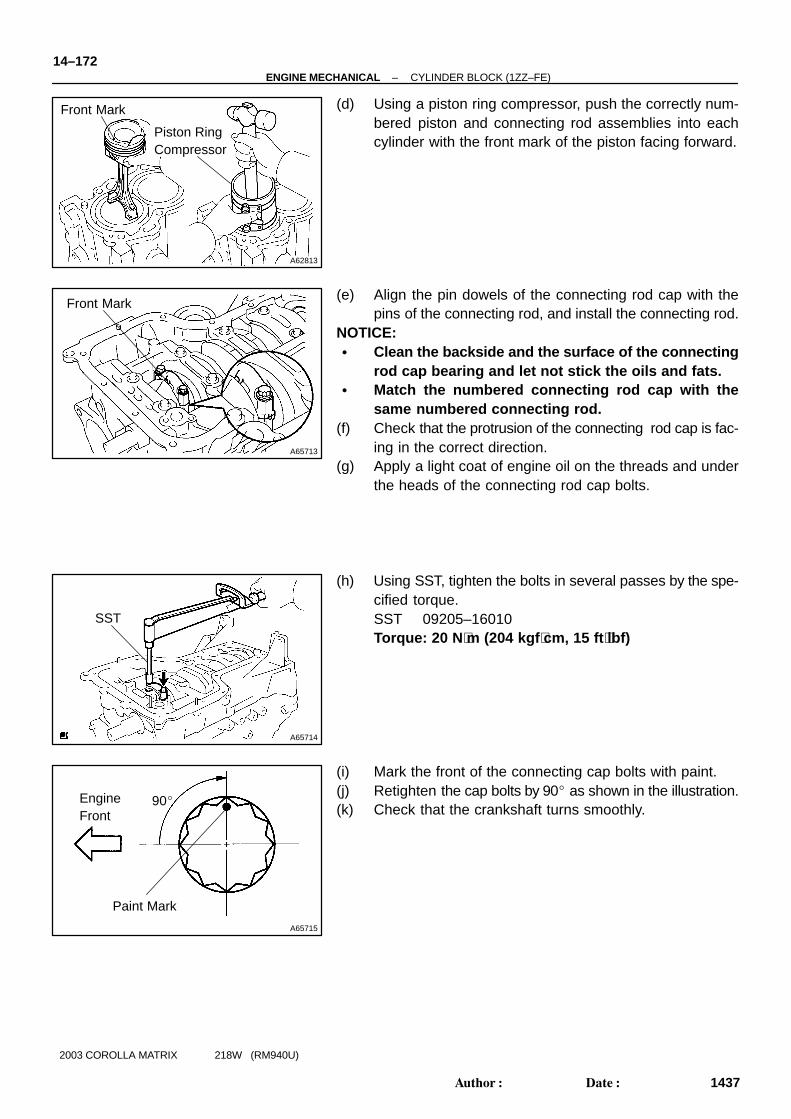
(d) Using a piston ring compressor, push the correctly num-bered piston and connecting rod assemblies into eachcylinder with the front mark of the piston facing forward.
(e) Align the pin dowels of the connecting rod cap with thepins of the connecting rod, and install the connecting rod.
NOTICE:� Clean the backside and the surface of the connecting
rod cap bearing and let not stick the oils and fats.� Match the numbered connecting rod cap with the
same numbered connecting rod.(f) Check that the protrusion of the connecting rod cap is fac-
ing in the correct direction.(g) Apply a light coat of engine oil on the threads and under
the heads of the connecting rod cap bolts.
(h) Using SST, tighten the bolts in several passes by the spe-cified torque.SST 09205–16010Torque: 20 N ⋅m (204 kgf ⋅cm, 15 ft ⋅lbf)
(i) Mark the front of the connecting cap bolts with paint.(j) Retighten the cap bolts by 90� as shown in the illustration.(k) Check that the crankshaft turns smoothly.

A64845
–ENGINE MECHANICAL CYLINDER BLOCK (1ZZ–FE)14–173
1438Author�: Date�:
2003 COROLLA MATRIX 218W (RM940U)
35. INSTALL CYLINDER BLOCK WATER DRAIN COCKSUB–ASSY
(a) Apply 2 or 3 threads of adhesive to the cylinder block wa-ter drain cock, and install it within 3 minutes.Torque: 25 N ⋅m (255 kgf ⋅cm, 18 ft ⋅lbf)Adhesive: Part No. 08833–00080, THREE BOND 1344, LOCTITE242 or equivalent
(b) After applying the specified torque, rotate the cylinderblock water drain cock clockwise until its drain port facesdownward.
NOTICE:� Do not put into coolant in an hour after the installa-
tion.� Do not rotate the drain union more than 360 � in (b),
and never loosen it after setting the union correctly.