engine control unit - ecotrons engine control unit... · 3 iacc idle speed motor drive c output...
TRANSCRIPT

Engine Control Unit
(ECU)
Technical Spec
ECOTRONS LLC
COPY RIGHTS ECOTRONS
ALL RIGHTS RESERVED
Note: If you are not sure about any specific details,
please contact us at [email protected].

Product: Engine Control Unit
Type: EC4T2CTHIGIA
Comment: All the data in the document are tests under
normal conditions
Index Page Revision Date Note
1 ---- First Edition 5.19.2015 V1.1
2 ---- Second Edition 2.15.2017 V1.2
Contents
1 Overview
2 Characteristic and principle
3 Technical parameters
4 Installations
5 Instructions
6 Malfunction Indicators and Elimination
7 Appendix: mechanical CAD size

Engine Control Unit(EC4T2CTHIGIA) technical spec-V1.2
1 Copy rights ECOTRONS LLC http://www.ecotrons.com
1 Overview
The core part of Ecotrons ECU is FreeScale’s 16 bit or 32 bit microprocessor that
is specifically designed for powertrain controls. ECU also includes some
Application Specific Integrated Circuits, or ASIC chips, from world famous
automotive semiconductor manufacturers, like Infineon, and International
Rectifier etc. Most importantly, Ecotrons’ ECU contains the state-of-art engine
control software which combines both efficiency and flexibility of the modern
engine control technology.
Ecotrons has a few small engine ECUs; all small sizes and light weight. One is
like the below picture, water proof.
2 Characteristic and principle
2.1 Characteristics
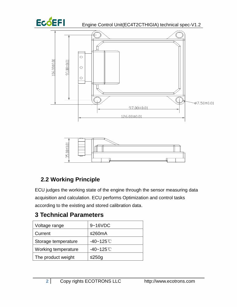
The 24-pin ECU with an aluminum shell is sealed by pouring sealant. And
there are mounting holes on the shell.
ECU shape size.
Engine Control Unit(EC4T2CTHIGIA) technical spec-V1.2
2 Copy rights ECOTRONS LLC http://www.ecotrons.com
2.2 Working Principle
ECU judges the working state of the engine through the sensor measuring data
acquisition and calculation. ECU performs Optimization and control tasks
according to the existing and stored calibration data.
3 Technical Parameters
Voltage range 9~16VDC
Current ≤260mA
Storage temperature -40~125℃
Working temperature -40~125℃
The product weight ≤250g

Engine Control Unit(EC4T2CTHIGIA) technical spec-V1.2
3 Copy rights ECOTRONS LLC http://www.ecotrons.com
4 Installations
4.1 Installation location
In order to ensure a high reliability, ECU installation should abide by the following
principles:
Mounting position of ECU should have adequate ventilation.
Avoid the heat transmission to the ECU.
Away from the ignition system, the EMI is serious.
It should be installed firmly.
Avoid the dirty, wet, and splash water.
Don't let the ECU to prop up the wiring harness.
Wiring harness should avoid wear and heat.
4.2 Temperature Adaptability
The temperature of location must under the limit (125 o C at any time.
4.3 Waterproof Requirements
The water cannot gather near the ECU connector. It may cause a short.
All the possibility of contact with water should be ruled out.

Engine Control Unit(EC4T2CTHIGIA) technical spec-V1.2
4 Copy rights ECOTRONS LLC http://www.ecotrons.com
5 The Instructions
5.1 System Function
ECT
MAP
TPS
O2 sensor
CKP+
IAT
A/D
Speed acquisi
tion
Switch signal
Communicati
on
Jet drive
RS232
Ignitiondrive
Coil 2
INJ2
INJ1
KEYSW
ECU
Motordrive
Idle Motor
ROUT
Coils 1
CKP-
Abbreviation:
IAT: Intake Air Temperature Sensor
ECT: Engine (Coolant) Temperature or Cylinder Head Temperature Sensor
MAP: Manifold Absolute Pressure Sensor
TPS: Throttle Position Sensor
KEYSW: Key Switch or Ignition Switch input
CKP: Crank Position Sensor
ROUT: Relay control Output
INJ: Injector control output
Coil: Inductive ignition coils

Engine Control Unit(EC4T2CTHIGIA) technical spec-V1.2
5 Copy rights ECOTRONS LLC http://www.ecotrons.com
Control Strategy Block Diagram:
Engine Control Unit(EC4T2CTHIGIA) technical spec-V1.2
6 Copy rights ECOTRONS LLC http://www.ecotrons.com
Control Strategy Block Diagram (as above)
Major control strategies:
• Charge detection and prediction.
• Fuel injection controls.
• Ignition system controls.
• Fuel pump controls.
• EVAP emission controls.
• Transient fuel compensations.
• Decel-fuel-cut-off.
• Altitude compensations.
• Temperature compensations (winter, summer, etc.).
• Engine protections.
• Diagnostics and serial communications.
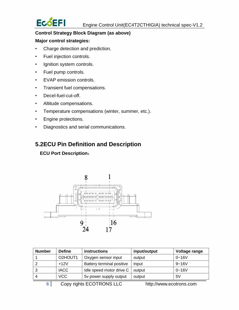
5.2 ECU Pin Definition and Description
ECU Port Description:
Number Define instructions input/output Voltage range
1 O2HOUT1 Oxygen sensor input output 0~16V
2 +12V Battery terminal positive Input 9~16V
3 IACC Idle speed motor drive C output 0~16V
4 VCC 5v power supply output output 5V

Engine Control Unit(EC4T2CTHIGIA) technical spec-V1.2
7 Copy rights ECOTRONS LLC http://www.ecotrons.com
5 RXD serial port
communication sender
output -15~+15V
6 IACA Idle speed motor drive A output 0~16V
7 TPS Throttle position sensor Input 0~5V
8 GND-A Sensor ground output 0
9 CKP- The negative of crank
position sensor input
output 0~16V
10 MAP Manifold air pressure Input 0~5V
11 IACD Idle speed motor drive D output 0~16V
12 TXD serial port
communication receiver
Input -15~+15V
13 IAT Intake air temperature
sensor input
Input 0~5V
14 KEYSW Key switch Input 0~16V
15 INJ2 Fuel injector # 2 driver
output
Output 0~16V
16 INJ1 Fuel injector # 1 driver
output
Output 0~16V
17 GND-P Power ground Output 0
18 COIL1 Ignition Coil #1 driver
output
Output 0~16V
19 COIL2 Ignition Coil #2 driver
output
Output 0~16V
20 ROUT fuel pump relay driver
output
Output 0~16 V
21 ECT The engine temperature
sensor
Input 0~5 V
22 IACB Idle speed motor drive B Output 0~16V
23 O2IN1 Oxygen sensor input Input 0~1V
24 CKP+ The positive of crank
position sensor input
Input 2~150V
5.3 ECU function module
5.3.1 Analog Signal Acquisition Channel
AD conversion channel can convert analog signals from sensor to digital signals.
The ECU can get signals from the sensors, like the air temperature sensor,
engine temperature sensor, air pressure sensor, throttle position sensor and
oxygen sensor signal.

Engine Control Unit(EC4T2CTHIGIA) technical spec-V1.2
8 Copy rights ECOTRONS LLC http://www.ecotrons.com
5.3.2 CKP Signal Acquisition
The CKP signal is extracted from the engine ignition trigger sensor, the voltage of
original signal is high, so it must be converted into a 0~5V digital pulse
voltage, can be processed to identify ECU, then ECU can get the information
of engine speed and piston position . The voltage of signal from trigger sensor
must be higher than 2V.
5.3.3 Fuel Injector Drive
Fuel injector drive circuit
MCU can control the MOSFET to be ON or OFF, and then the injector will be ON
or OFF. So the ECU can control the injector to inject the accurately fuel. For
gasoline engine, the stoic AFR (air/fuel ratio) is 14.7.
5.3.4 Ignition control
In ECU, MCU can control the IGBT to be ON and OFF, and then the ignition coil
will be charging and fire. So the ECU can control the ignition coil to fire at a
suitable ignition timing.
Note: the EC4T2CTHIGIA ECU cannot driver a CDI directly.
5.4 Matters Needing Attention
In the installation, the ECU should be installed at the end to reduce the
damage of the electrostatic.
The power supply should be disconnected before the ECU is installed.
For the first time to use the ECU, in order to get the right TPS information,

Engine Control Unit(EC4T2CTHIGIA) technical spec-V1.2
9 Copy rights ECOTRONS LLC http://www.ecotrons.com
please operate as following:
Close the throttle , in the idle position;
Key on, waiting for more than 5 seconds;
Open the throttle fully, waiting for more than 5 seconds;
Close the key switch, waiting for more than 5 seconds.
Try to avoid ECU suffered more than 16V voltages.
ECU should be stored in a dry, dust-free environment, not exposed to any
liquid waste.
6 Malfunction Indicator and Elimination
The fault phenomenon Cause analysis Elimination method
Trouble light shining Parts are bad According to the
software read failure
After open the key switch, oil
pump does not work
1. The ECU without
electricity
2. The relay is
damaged
3. The ECU has been
damaged
1. Check the red
power cord and
fuse
2. Replace the relay
3. Replace the ECU

Engine Control Unit(EC4T2CTHIGIA) technical spec-V1.2
10 Copy rights ECOTRONS LLC http://www.ecotrons.com
7. Appendix: Mechanical CAD Size