engine co a service...refilling engine cooling system kv991j0010 (j-23688) engine coolant...
TRANSCRIPT

ENGINE
C
D
E
SECTION CO A
CO
ENGINE COOLING SYSTEM
F
G
H
I
J
K
L
M
N
O
P
CONTENTS
VQ35DE
PRECAUTION ............................................... 2
PRECAUTIONS ................................................... 2Precaution for Supplemental Restraint System (SRS) "AIR BAG" and "SEAT BELT PRE-TEN-SIONER" ...................................................................2Precaution for Liquid Gasket .....................................2
PREPARATION ............................................ 4
PREPARATION ................................................... 4Special Service Tool .................................................4Commercial Service Tool ..........................................4
SYSTEM DESCRIPTION .............................. 6
OVERHEATING CAUSE ANALYSIS .................. 6Troubleshooting Chart ...............................................6
COOLING SYSTEM ............................................ 8Cooling Circuit ...........................................................8Schematic .................................................................8
PERIODIC MAINTENANCE .......................... 9
ENGINE COOLANT ............................................ 9System Inspection .....................................................9Changing Engine Coolant .......................................10
REMOVAL AND INSTALLATION ...............13
RADIATOR ........................................................13Removal and Installation .........................................13
COOLING FAN ..................................................15Removal and Installation .........................................15
WATER PUMP ..................................................16Exploded View .........................................................16Removal and Installation .........................................16
THERMOSTAT AND THERMOSTAT HOUS-ING ....................................................................20
Removal and Installation .........................................20
WATER OUTLET AND WATER PIPING ..........22Removal and Installation .........................................22
UNIT DISASSEMBLY AND ASSEMBLY ....24
COOLING FAN ..................................................24Disassembly and Assembly .....................................24
SERVICE DATA AND SPECIFICATIONS (SDS) ............................................................25
SERVICE DATA AND SPECIFICATIONS (SDS) .................................................................25
Capacity ...................................................................25Thermostat ..............................................................25Radiator ...................................................................25
CO-1Revision: January 2012 2011 Maxima
[VQ35DE]PRECAUTIONS
< PRECAUTION >
PRECAUTIONPRECAUTIONSPrecaution for Supplemental Restraint System (SRS) "AIR BAG" and "SEAT BELT PRE-TENSIONER" INFOID:0000000006708611
The Supplemental Restraint System such as “AIR BAG” and “SEAT BELT PRE-TENSIONER”, used alongwith a front seat belt, helps to reduce the risk or severity of injury to the driver and front passenger for certaintypes of collision. This system includes seat belt switch inputs and dual stage front air bag modules. The SRSsystem uses the seat belt switches to determine the front air bag deployment, and may only deploy one frontair bag, depending on the severity of a collision and whether the front occupants are belted or unbelted.Information necessary to service the system safely is included in the SR and SB section of this Service Man-ual.WARNING:• To avoid rendering the SRS inoperative, which could increase the risk of personal injury or death in
the event of a collision which would result in air bag inflation, all maintenance must be performed byan authorized NISSAN/INFINITI dealer.
• Improper maintenance, including incorrect removal and installation of the SRS, can lead to personalinjury caused by unintentional activation of the system. For removal of Spiral Cable and Air BagModule, see the SR section.
• Do not use electrical test equipment on any circuit related to the SRS unless instructed to in thisService Manual. SRS wiring harnesses can be identified by yellow and/or orange harnesses or har-ness connectors.
PRECAUTIONS WHEN USING POWER TOOLS (AIR OR ELECTRIC) AND HAMMERSWARNING:• When working near the Airbag Diagnosis Sensor Unit or other Airbag System sensors with the Igni-
tion ON or engine running, DO NOT use air or electric power tools or strike near the sensor(s) with ahammer. Heavy vibration could activate the sensor(s) and deploy the air bag(s), possibly causingserious injury.
• When using air or electric power tools or hammers, always switch the Ignition OFF, disconnect thebattery, and wait at least 3 minutes before performing any service.
Precaution for Liquid Gasket INFOID:0000000006237152
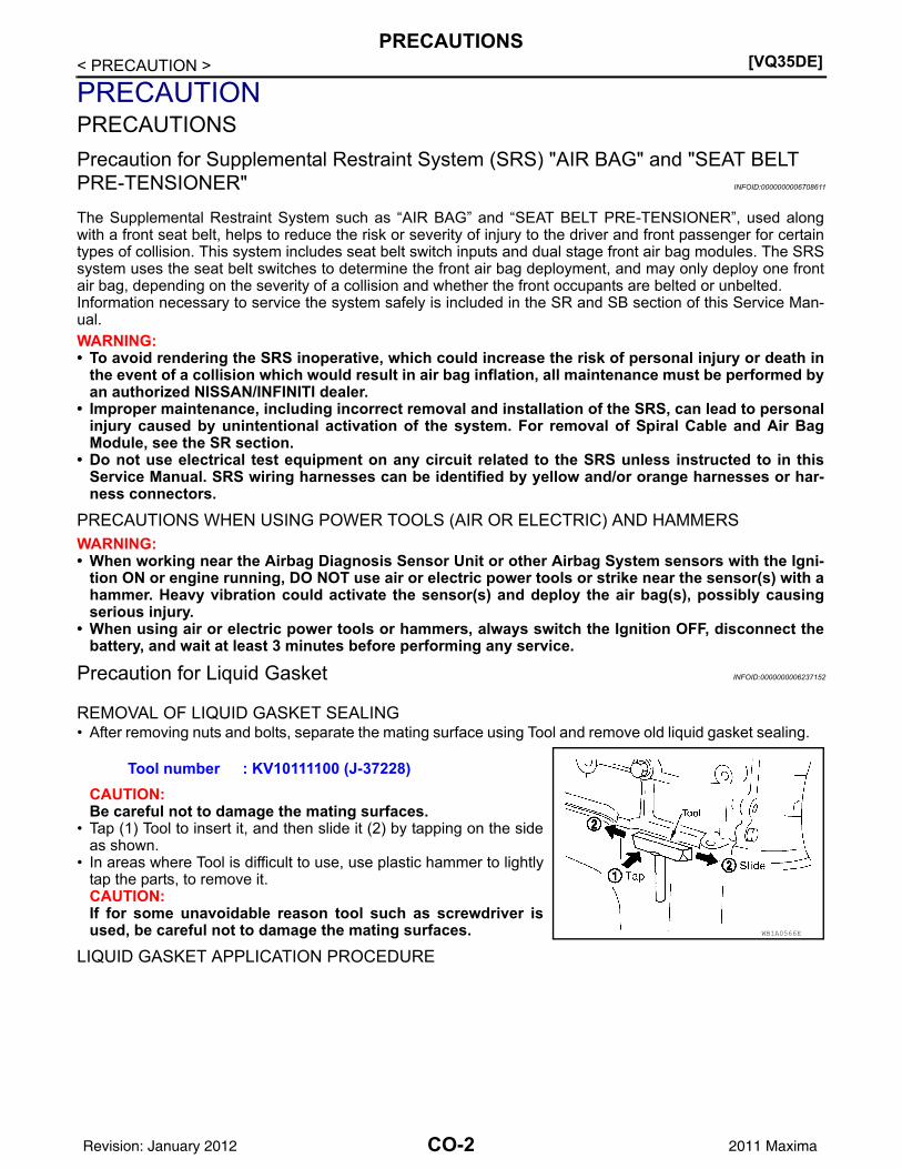
REMOVAL OF LIQUID GASKET SEALING• After removing nuts and bolts, separate the mating surface using Tool and remove old liquid gasket sealing.
CAUTION:Be careful not to damage the mating surfaces.
• Tap (1) Tool to insert it, and then slide it (2) by tapping on the sideas shown.
• In areas where Tool is difficult to use, use plastic hammer to lightlytap the parts, to remove it.CAUTION:If for some unavoidable reason tool such as screwdriver isused, be careful not to damage the mating surfaces.
LIQUID GASKET APPLICATION PROCEDURE
Tool number : KV10111100 (J-37228)
WBIA0566E
CO-2Revision: January 2012 2011 Maxima

PRECAUTIONS[VQ35DE]
C
D
E
F
G
H
I
J
K
L
M
A
O
N
P
O
< PRECAUTION >
C
1. Remove old liquid gasket adhering to the liquid gasket applica-tion surface and the mating surface using scraper.• Remove liquid gasket completely from the groove of the liquid
gasket application surface, bolts, and bolt holes.2. Thoroughly clean the mating surfaces and remove adhering
moisture, grease and foreign materials.
3. Attach liquid gasket tube to Tool.
Use Genuine RTV Silicone Sealant or equivalent. Refer toGI-15, "Recommended Chemical Products and Sealants".
4. Apply liquid gasket without breaks to the specified location with the specified dimensions.• If there is a groove for the liquid gasket application, apply liq-
uid gasket to the groove.• As for the bolt holes, normally apply liquid gasket inside the
holes. Occasionally, it should be applied outside the holes.Make sure to read the text of Service Manual.
• Within five minutes of liquid gasket application, install the mat-ing component.
• If liquid gasket protrudes, wipe it off immediately.• Do not retighten nuts or bolts after the installation.• After 30 minutes or more have passed from the installation, fill
engine oil and engine coolant.CAUTION:Carefully follow all of the warnings, cautions, notes, and procedures contained in this manual.
PBIC0003E
Tool number : WS39930000 ( — )
WBIA0567E
SEM159F
CO-3Revision: January 2012 2011 Maxima

[VQ35DE]PREPARATION
< PREPARATION >
PREPARATIONPREPARATIONSpecial Service Tool INFOID:0000000006237153
The actual shapes of Kent-Moore tools may from those of special service tools illustrated here.
Commercial Service Tool INFOID:0000000006237154
Tool number(Kent-Moore No.)Tool name
Description
WS39930000( — )Tube pressure
Pressing the tube of liquid gasket
EG17650301(J-33984-A)Radiator cap tester adapter
Adapting radiator cap tester to radiator cap and radiator filler necka: 28 (1.10) dia.b: 31.4 (1.236) dia.c: 41.3 (1.626) dia.Unit: mm (in)
KV10111100(J-37228)Seal cutter
Removing chain tensioner cover and water pump cover
KV991J0070(J-45695)Coolant refill tool
Refilling engine cooling system
KV991J0010(J-23688)Engine coolant refractometer
Checking concentration of ethylene glycol in engine coolant
S-NT052
S-NT564
NT046
LMA053
WBIA0539E
CO-4Revision: January 2012 2011 Maxima
PREPARATION[VQ35DE]
C
D
E
F
G
H
I
J
K
L
M
A
O
N
P
O
< PREPARATION >
C
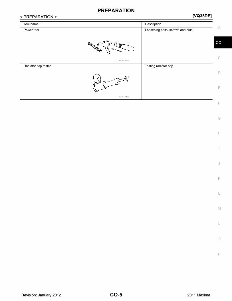
Tool name Description
Power tool Loosening bolts, screws and nuts
Radiator cap tester Testing radiator cap
PIIB1407E
PBIC1982E
CO-5Revision: January 2012 2011 Maxima

[VQ35DE]OVERHEATING CAUSE ANALYSIS
< SYSTEM DESCRIPTION >
SYSTEM DESCRIPTIONOVERHEATING CAUSE ANALYSISTroubleshooting Chart INFOID:0000000006237155
Symptom Check items
Cooling sys-tem parts malfunction
Poor heat transfer
Water pump malfunction Worn or loose drive belt
—
Thermostat stuck closed —
Damaged finsDust contamination or pa-per clogging
Physical damage
Clogged radiator cooling tube
Excess foreign material (rust, dirt, sand, etc.)
Reduced air flow
Cooling fan does not oper-ate
Fan assembly —High resistance to fan rota-tion
Damaged fan blades
Damaged radiator shroud — Radiator shroud —
Improper coolant mixture ratio —
Coolant viscosity—
Poor coolant quality — —
Insufficient coolant
Coolant leaks
Cooling hoseLoose clamp
Cracked hose
Water pump Poor sealing
Radiator capLoose
Poor sealing
Radiator
O-ring for damage, deterio-ration or improper fitting
Cracked radiator tank
Cracked radiator core
Reservoir tank Cracked reservoir tank
Overflowing reservoir tank Exhaust gas leaks into cool-ing system
Cylinder head deterioration
Cylinder head gasket deteri-oration
CO-6Revision: January 2012 2011 Maxima

OVERHEATING CAUSE ANALYSIS[VQ35DE]
C
D
E
F
G
H
I
J
K
L
M
A
O
N
P
O
< SYSTEM DESCRIPTION >
C
Except cool-ing system parts mal-function
— Overload on engine
Abusive driving
High engine rpm under no load
Driving in low gear for ex-tended time
Driving at extremely high speed
Powertrain system malfunc-tion
—Installed improper size wheels and tires
Dragging brakes
Improper ignition timing
Blocked or restricted air flow
Blocked bumper Blocked air flow
—
Blocked radiator grilleInstalled car brassiere
Mud contamination or paper clogging
Blocked radiator
Blocked air flowBlocked condenser
Installed large fog lamp
Symptom Check items
CO-7Revision: January 2012 2011 Maxima
[VQ35DE]COOLING SYSTEM
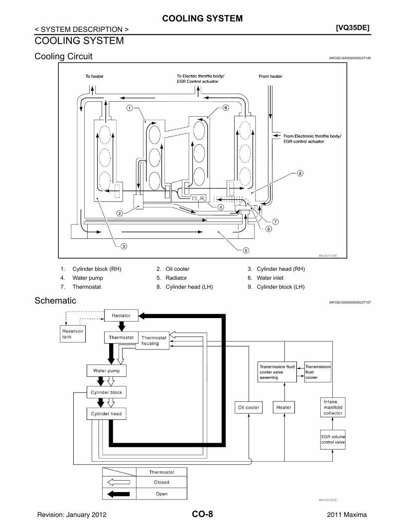
< SYSTEM DESCRIPTION >COOLING SYSTEMCooling Circuit INFOID:0000000006237156
Schematic INFOID:0000000006237157
WBIA0558E
1. Cylinder block (RH) 2. Oil cooler 3. Cylinder head (RH)4. Water pump 5. Radiator 6. Water inlet7. Thermostat 8. Cylinder head (LH) 9. Cylinder block (LH)
WBIA0562E
CO-8Revision: January 2012 2011 Maxima
ENGINE COOLANT[VQ35DE]
C
D
E
F
G
H
I
J
K
L
M
A
O
N
P
O
< PERIODIC MAINTENANCE >
C
PERIODIC MAINTENANCEENGINE COOLANTSystem Inspection INFOID:0000000006237158
WARNING:• Never remove the radiator cap when the engine is hot. Serious burns could occur from high pres-
sure coolant escaping from the radiator.• Wrap a thick cloth around the cap. Slowly push down and turn it a quarter turn to allow built-up pres-
sure to escape. Carefully remove the cap by pushing down and turning it all the way.
CHECKING COOLING SYSTEM HOSESCheck hoses for the following:• Improper attachment• Leaks• Cracks• Damage• Loose connections• Chafing• Deterioration
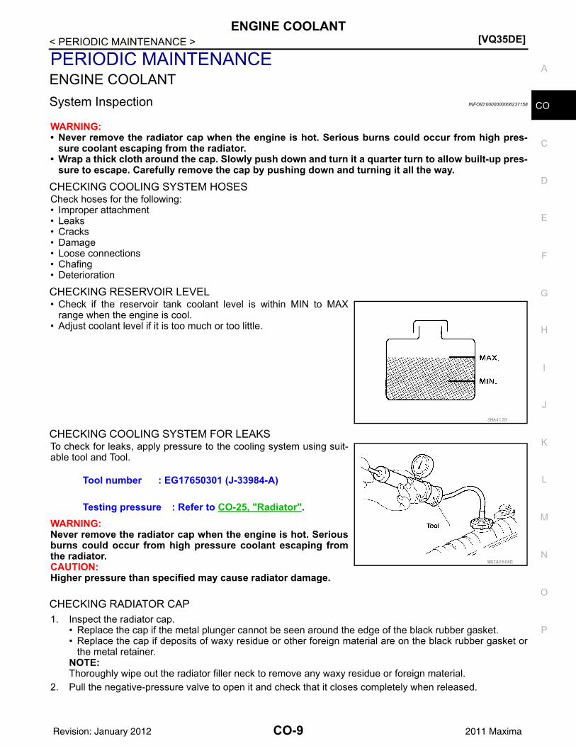
CHECKING RESERVOIR LEVEL• Check if the reservoir tank coolant level is within MIN to MAX
range when the engine is cool.• Adjust coolant level if it is too much or too little.
CHECKING COOLING SYSTEM FOR LEAKSTo check for leaks, apply pressure to the cooling system using suit-able tool and Tool.
WARNING:Never remove the radiator cap when the engine is hot. Seriousburns could occur from high pressure coolant escaping fromthe radiator.CAUTION:Higher pressure than specified may cause radiator damage.
CHECKING RADIATOR CAP1. Inspect the radiator cap.
• Replace the cap if the metal plunger cannot be seen around the edge of the black rubber gasket.• Replace the cap if deposits of waxy residue or other foreign material are on the black rubber gasket or
the metal retainer.NOTE:Thoroughly wipe out the radiator filler neck to remove any waxy residue or foreign material.
2. Pull the negative-pressure valve to open it and check that it closes completely when released.
SMA412B
Tool number : EG17650301 (J-33984-A)
Testing pressure : Refer to CO-25, "Radiator".
WBIA0568E
CO-9Revision: January 2012 2011 Maxima
[VQ35DE]ENGINE COOLANT
< PERIODIC MAINTENANCE >
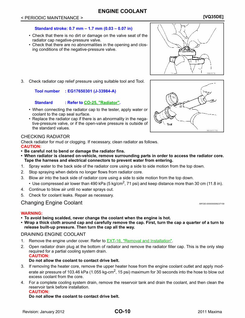
• Check that there is no dirt or damage on the valve seat of theradiator cap negative-pressure valve.
• Check that there are no abnormalities in the opening and clos-ing conditions of the negative-pressure valve.
3. Check radiator cap relief pressure using suitable tool and Tool.
• When connecting the radiator cap to the tester, apply water orcoolant to the cap seal surface.
• Replace the radiator cap if there is an abnormality in the nega-tive-pressure valve, or if the open-valve pressure is outside ofthe standard values.
CHECKING RADIATORCheck radiator for mud or clogging. If necessary, clean radiator as follows.CAUTION:• Be careful not to bend or damage the radiator fins.• When radiator is cleaned on-vehicle, remove surrounding parts in order to access the radiator core.
Tape the harness and electrical connectors to prevent water from entering.1. Spray water to the back side of the radiator core using a side to side motion from the top down. 2. Stop spraying when debris no longer flows from radiator core. 3. Blow air into the back side of radiator core using a side to side motion from the top down.
• Use compressed air lower than 490 kPa (5 kg/cm2, 71 psi) and keep distance more than 30 cm (11.8 in). 4. Continue to blow air until no water sprays out.5. Check for coolant leaks. Repair as necessary.
Changing Engine Coolant INFOID:0000000006237159
WARNING:• To avoid being scalded, never change the coolant when the engine is hot.• Wrap a thick cloth around cap and carefully remove the cap. First, turn the cap a quarter of a turn to
release built-up pressure. Then turn the cap all the way.
DRAINING ENGINE COOLANT1. Remove the engine under cover. Refer to EXT-16, "Removal and Installation".2. Open radiator drain plug at the bottom of radiator and remove the radiator filler cap. This is the only step
required for a partial cooling system drain. CAUTION:Do not allow the coolant to contact drive belt.
3. If removing the heater core, remove the upper heater hose from the engine coolant outlet and apply mod-erate air pressure of 103.46 kPa (1.055 kg-cm2, 15 psi) maximum for 30 seconds into the hose to blow outexcess coolant from the core.
4. For a complete cooling system drain, remove the reservoir tank and drain the coolant, and then clean thereservoir tank before installation.CAUTION:Do not allow the coolant to contact drive belt.
Standard stroke: 0.7 mm – 1.7 mm (0.03 – 0.07 in)
SMA967B
Tool number : EG17650301 (J-33984-A)
Standard : Refer to CO-25, "Radiator".
WBIA0570E
CO-10Revision: January 2012 2011 Maxima
ENGINE COOLANT[VQ35DE]
C
D
E
F
G
H
I
J
K
L
M
A
O
N
P
O
< PERIODIC MAINTENANCE >
C
5. When performing a complete cooling system drain remove the cylinder block front drain plug and the cyl-inder block RH drain plug.
6. Check the drained coolant for contaminants such as rust, corrosion or discoloration.• If contaminated, flush the engine cooling system.
REFILLING ENGINE COOLANT1. Install the radiator drain plug. If the cooling system was drained completely, install the reservoir tank and
the cylinder block drain plugs.• The radiator must be completely empty of coolant and water.• Apply sealant to the threads of the cylinder block drain plugs. Use Genuine High Performance Thread
Sealant or equivalent. Refer to GI-15, "Recommended Chemical Products and Sealants".
2. If disconnected, reattach the upper radiator hose at the engine side.3. Set the vehicle heater controls to the full HOT and heater ON position. Turn the vehicle ignition ON with
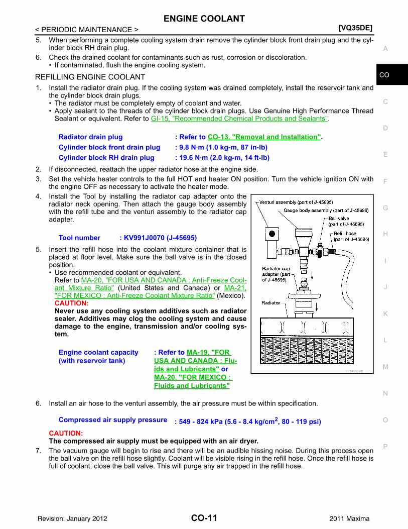
the engine OFF as necessary to activate the heater mode.4. Install the Tool by installing the radiator cap adapter onto the
radiator neck opening. Then attach the gauge body assemblywith the refill tube and the venturi assembly to the radiator capadapter.
5. Insert the refill hose into the coolant mixture container that isplaced at floor level. Make sure the ball valve is in the closedposition. • Use recommended coolant or equivalent.
Refer to MA-20, "FOR USA AND CANADA : Anti-Freeze Cool-ant Mixture Ratio" (United States and Canada) or MA-21,"FOR MEXICO : Anti-Freeze Coolant Mixture Ratio" (Mexico).CAUTION:Never use any cooling system additives such as radiatorsealer. Additives may clog the cooling system and causedamage to the engine, transmission and/or cooling sys-tem.
6. Install an air hose to the venturi assembly, the air pressure must be within specification.
CAUTION:The compressed air supply must be equipped with an air dryer.
7. The vacuum gauge will begin to rise and there will be an audible hissing noise. During this process openthe ball valve on the refill hose slightly. Coolant will be visible rising in the refill hose. Once the refill hose isfull of coolant, close the ball valve. This will purge any air trapped in the refill hose.
Radiator drain plug : Refer to CO-13, "Removal and Installation".Cylinder block front drain plug : 9.8 N·m (1.0 kg-m, 87 in-lb)Cylinder block RH drain plug : 19.6 N·m (2.0 kg-m, 14 ft-lb)
Tool number : KV991J0070 (J-45695)
Engine coolant capacity (with reservoir tank)
: Refer to MA-19, "FOR USA AND CANADA : Flu-ids and Lubricants" or MA-20, "FOR MEXICO : Fluids and Lubricants"
LLIA0058E
Compressed air supply pressure : 549 - 824 kPa (5.6 - 8.4 kg/cm2, 80 - 119 psi)
CO-11Revision: January 2012 2011 Maxima
[VQ35DE]ENGINE COOLANT
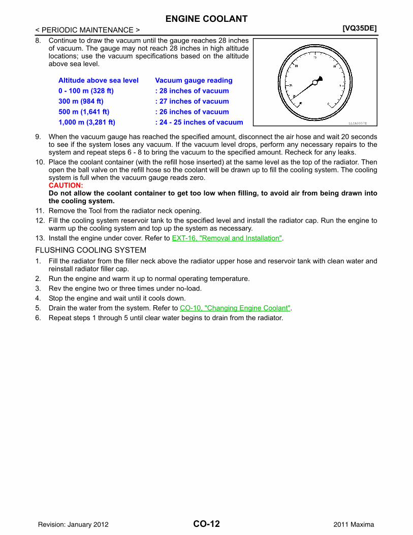
< PERIODIC MAINTENANCE >8. Continue to draw the vacuum until the gauge reaches 28 inches
of vacuum. The gauge may not reach 28 inches in high altitudelocations; use the vacuum specifications based on the altitudeabove sea level.
9. When the vacuum gauge has reached the specified amount, disconnect the air hose and wait 20 secondsto see if the system loses any vacuum. If the vacuum level drops, perform any necessary repairs to thesystem and repeat steps 6 - 8 to bring the vacuum to the specified amount. Recheck for any leaks.
10. Place the coolant container (with the refill hose inserted) at the same level as the top of the radiator. Thenopen the ball valve on the refill hose so the coolant will be drawn up to fill the cooling system. The coolingsystem is full when the vacuum gauge reads zero.CAUTION:Do not allow the coolant container to get too low when filling, to avoid air from being drawn intothe cooling system.
11. Remove the Tool from the radiator neck opening.12. Fill the cooling system reservoir tank to the specified level and install the radiator cap. Run the engine to
warm up the cooling system and top up the system as necessary.13. Install the engine under cover. Refer to EXT-16, "Removal and Installation".
FLUSHING COOLING SYSTEM1. Fill the radiator from the filler neck above the radiator upper hose and reservoir tank with clean water and
reinstall radiator filler cap. 2. Run the engine and warm it up to normal operating temperature.3. Rev the engine two or three times under no-load.4. Stop the engine and wait until it cools down.5. Drain the water from the system. Refer to CO-10, "Changing Engine Coolant".6. Repeat steps 1 through 5 until clear water begins to drain from the radiator.
Altitude above sea level Vacuum gauge reading0 - 100 m (328 ft) : 28 inches of vacuum300 m (984 ft) : 27 inches of vacuum500 m (1,641 ft) : 26 inches of vacuum1,000 m (3,281 ft) : 24 - 25 inches of vacuum LLIA0057E
CO-12Revision: January 2012 2011 Maxima
RADIATOR[VQ35DE]
C
D
E
F
G
H
I
J
K
L
M
A
O
N
P
O
< REMOVAL AND INSTALLATION >
C
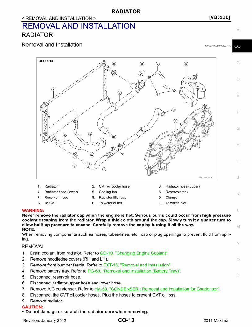
REMOVAL AND INSTALLATIONRADIATORRemoval and Installation INFOID:0000000006237160
WARNING:Never remove the radiator cap when the engine is hot. Serious burns could occur from high pressurecoolant escaping from the radiator. Wrap a thick cloth around the cap. Slowly turn it a quarter turn toallow built-up pressure to escape. Carefully remove the cap by turning it all the way. NOTE:When removing components such as hoses, tubes/lines, etc., cap or plug openings to prevent fluid from spill-ing.
REMOVAL1. Drain coolant from radiator. Refer to CO-10, "Changing Engine Coolant".2. Remove hoodledge covers (RH and LH).3. Remove front bumper fascia. Refer to EXT-16, "Removal and Installation".4. Remove battery tray. Refer to PG-69, "Removal and Installation (Battery Tray)".5. Disconnect reservoir hose.6. Disconnect radiator upper hose and lower hose.7. Remove A/C condenser. Refer to HA-50, "CONDENSER : Removal and Installation for Condenser".8. Disconnect the CVT oil cooler hoses. Plug the hoses to prevent CVT oil loss.9. Remove radiator.CAUTION:• Do not damage or scratch the radiator core when removing.
1. Radiator 2. CVT oil cooler hose 3. Radiator hose (upper)4. Radiator hose (lower) 5. Cooling fan 6. Reservoir tank7. Reservoir hose 8. Radiator filler cap 9. ClampsA. To CVT B. To water outlet C. To water inlet
AWBIA0682GB
CO-13Revision: January 2012 2011 Maxima
[VQ35DE]RADIATOR
< REMOVAL AND INSTALLATION >INSTALLATIONInstallation is in the reverse order of removal.• After installation refill engine coolant and check for leaks. Refer to CO-10, "Changing Engine Coolant" and
CO-9, "System Inspection". CAUTION:Do not spill coolant in engine compartment. Use a shop cloth to absorb coolant.
INSPECTIONRadiator1. Check radiator for mud or clogging. If necessary, clean radiator as follows.
CAUTION:• Be careful not to bend or damage the radiator fins.• When radiator is cleaned on-vehicle, remove surrounding parts in order to access the radiator
core. Tape the harness and electrical connectors to prevent water from entering.2. Spray water to the back side of the radiator core using a side to side motion from the top down. 3. Stop spraying when debris no longer flows from radiator core. 4. Blow air into the back side of radiator core using a side to side motion from the top down.
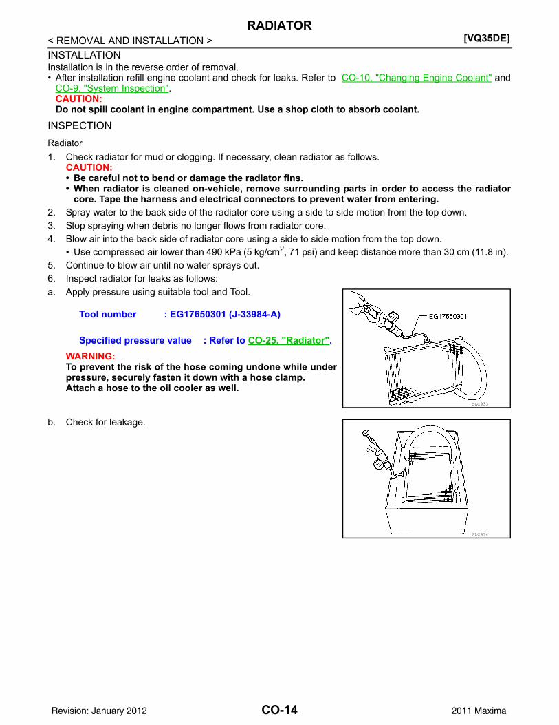
• Use compressed air lower than 490 kPa (5 kg/cm2, 71 psi) and keep distance more than 30 cm (11.8 in). 5. Continue to blow air until no water sprays out.6. Inspect radiator for leaks as follows:a. Apply pressure using suitable tool and Tool.
WARNING:To prevent the risk of the hose coming undone while underpressure, securely fasten it down with a hose clamp.Attach a hose to the oil cooler as well.
b. Check for leakage.
Tool number : EG17650301 (J-33984-A)
Specified pressure value : Refer to CO-25, "Radiator".
SLC933
SLC934
CO-14Revision: January 2012 2011 Maxima
COOLING FAN[VQ35DE]
C
D
E
F
G
H
I
J
K
L
M
A
O
N
P
O
< REMOVAL AND INSTALLATION >
C
COOLING FANRemoval and Installation INFOID:0000000006237161
WARNING:Never remove the radiator cap when the engine is hot. Serious burns could occur from high pressurecoolant escaping from the radiator. Wrap a thick cloth around the cap. Slowly turn it a quarter turn toallow built-up pressure to escape. Carefully remove the cap by turning it all the way. NOTE:When removing components such as hoses, tubes/lines, etc., cap or plug openings to prevent fluid from spill-ing.
REMOVAL1. Partially drain engine coolant from radiator. Refer to CO-10, "Changing Engine Coolant".
CAUTION:Perform when engine is cold.
2. Remove engine room cover.3. Remove TCM. Refer to TM-161, "Removal and Installation".4. Remove battery tray. Refer to PG-69, "Removal and Installation (Battery Tray)".5. Disconnect radiator hose (upper).6. Disconnect fan motor connectors.7. Remove radiator cooling fan assembly.
INSTALLATIONInstallation is in the reverse order of removal.• Cooling fans are controlled by ECM. For details, refer to EC-485, "Description".
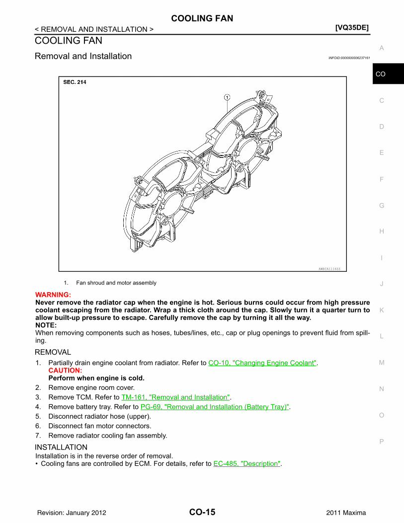
1. Fan shroud and motor assembly
AWBIA1116ZZ
CO-15Revision: January 2012 2011 Maxima
[VQ35DE]WATER PUMP
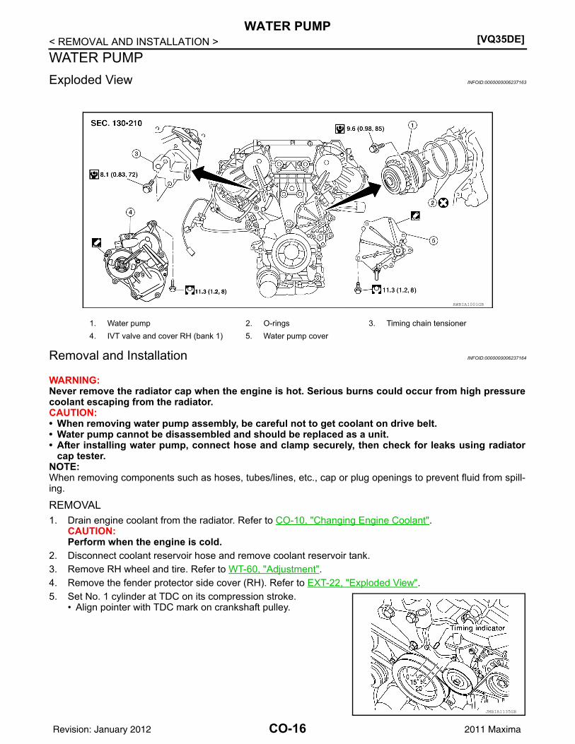
< REMOVAL AND INSTALLATION >WATER PUMPExploded View INFOID:0000000006237163
Removal and Installation INFOID:0000000006237164
WARNING:Never remove the radiator cap when the engine is hot. Serious burns could occur from high pressurecoolant escaping from the radiator.CAUTION:• When removing water pump assembly, be careful not to get coolant on drive belt.• Water pump cannot be disassembled and should be replaced as a unit.• After installing water pump, connect hose and clamp securely, then check for leaks using radiator
cap tester.NOTE:When removing components such as hoses, tubes/lines, etc., cap or plug openings to prevent fluid from spill-ing.
REMOVAL1. Drain engine coolant from the radiator. Refer to CO-10, "Changing Engine Coolant".
CAUTION:Perform when the engine is cold.
2. Disconnect coolant reservoir hose and remove coolant reservoir tank. 3. Remove RH wheel and tire. Refer to WT-60, "Adjustment".4. Remove the fender protector side cover (RH). Refer to EXT-22, "Exploded View".5. Set No. 1 cylinder at TDC on its compression stroke.
• Align pointer with TDC mark on crankshaft pulley.
AWBIA1001GB
1. Water pump 2. O-rings 3. Timing chain tensioner4. IVT valve and cover RH (bank 1) 5. Water pump cover
JMBIA1135GB
CO-16Revision: January 2012 2011 Maxima

WATER PUMP[VQ35DE]
C
D
E
F
G
H
I
J
K
L
M
A
O
N
P
O
< REMOVAL AND INSTALLATION >
C
6. Remove drive belt. Refer to EM-14, "Removal and Installation".7. Remove the idler pulley and the A/C idler pulley. Refer to EM-15, "Removal and Installation of Drive Belt
Auto-tensioner".8. Remove hoodledge cover (RH).9. Remove cylinder block front drain plug (1) on water pump side
of cylinder block to drain engine coolant from engine.
10. Support engine and remove the front engine insulator and bracket. Refer to EM-96, "Removal and Instal-lation".
11. Disconnect RH valve timing control connectors and remove IVT valve and cover RH (bank 1). Refer toEM-51, "Exploded View".
12. Remove water pump cover. Refer to EM-51, "Exploded View".13. Remove the timing chain tensioner (primary) as follows:a. Pull the lever (C) down to release the plunger stopper tab (B).b. Insert the stopper pin (A) into the tensioner body hole to hold the
lever (C) and keep the plunger stopper tab (B) released.NOTE:An allen wrench [(1.2 mm (0.047 in)] is used for a stopper pin(A) as an example.
c. Compress the plunger (D) into the tensioner body (1) by press-ing the slack guide (2).
d. Keep the slack guide (2) pressed and lock the plunger (D) in bypushing the stopper pin (A) through the lever (C) and into thechain tensioner body hole.
e. Remove timing chain tensioner bolts and then remove the timing chain tensioner.CAUTION:Be careful not to drop timing chain tensioner bolts inside timing chain case.
14. Remove the three water pump bolts (A). Make a gap betweenwater pump sprocket (1) and timing chain, by carefully turningcrankshaft pulley (2) counterclockwise until timing chain loosenson water pump sprocket (1).
AWBIA0902ZZ
AWBIA0903ZZ
AWBIA0904ZZ
CO-17Revision: January 2012 2011 Maxima
[VQ35DE]WATER PUMP
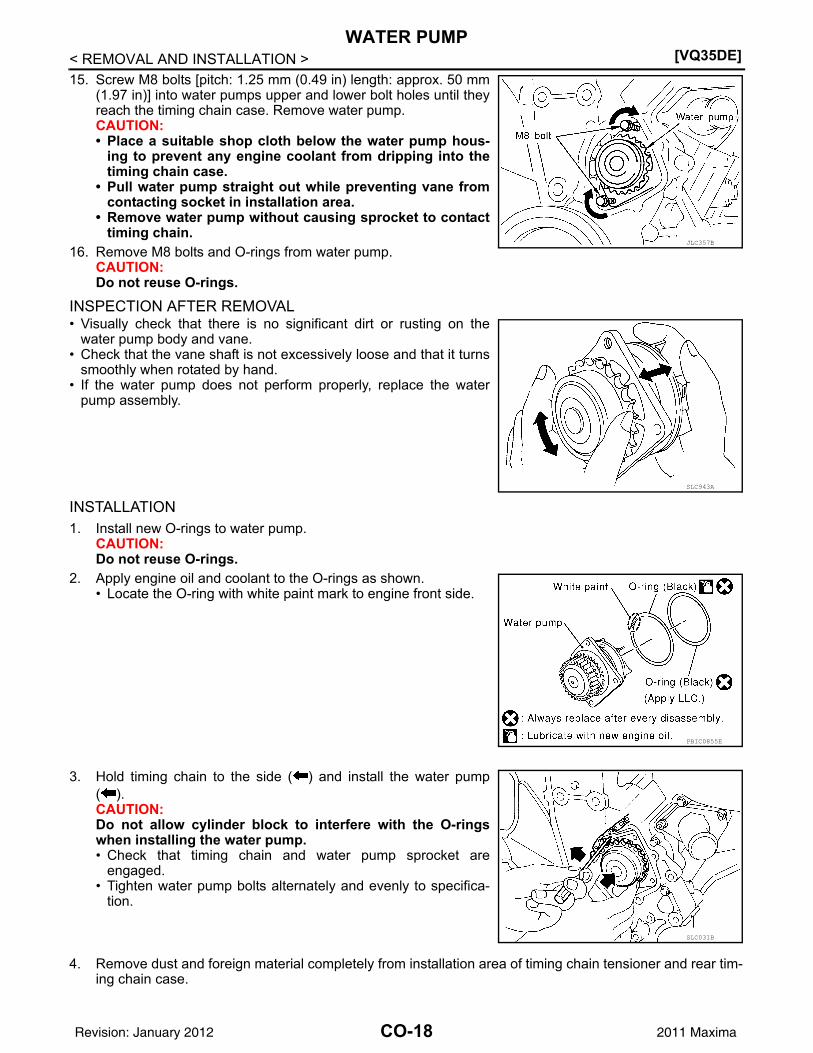
< REMOVAL AND INSTALLATION >15. Screw M8 bolts [pitch: 1.25 mm (0.49 in) length: approx. 50 mm
(1.97 in)] into water pumps upper and lower bolt holes until theyreach the timing chain case. Remove water pump.CAUTION:• Place a suitable shop cloth below the water pump hous-
ing to prevent any engine coolant from dripping into thetiming chain case.
• Pull water pump straight out while preventing vane fromcontacting socket in installation area.
• Remove water pump without causing sprocket to contacttiming chain.
16. Remove M8 bolts and O-rings from water pump.CAUTION:Do not reuse O-rings.
INSPECTION AFTER REMOVAL• Visually check that there is no significant dirt or rusting on the
water pump body and vane.• Check that the vane shaft is not excessively loose and that it turns
smoothly when rotated by hand. • If the water pump does not perform properly, replace the water
pump assembly.
INSTALLATION1. Install new O-rings to water pump.
CAUTION:Do not reuse O-rings.
2. Apply engine oil and coolant to the O-rings as shown.• Locate the O-ring with white paint mark to engine front side.
3. Hold timing chain to the side ( ) and install the water pump( ).CAUTION:Do not allow cylinder block to interfere with the O-ringswhen installing the water pump. • Check that timing chain and water pump sprocket are
engaged.• Tighten water pump bolts alternately and evenly to specifica-
tion.
4. Remove dust and foreign material completely from installation area of timing chain tensioner and rear tim-ing chain case.
JLC357B
SLC943A
PBIC0855E
SLC031B
CO-18Revision: January 2012 2011 Maxima
WATER PUMP[VQ35DE]
C
D
E
F
G
H
I
J
K
L
M
A
O
N
P
O
< REMOVAL AND INSTALLATION >
C
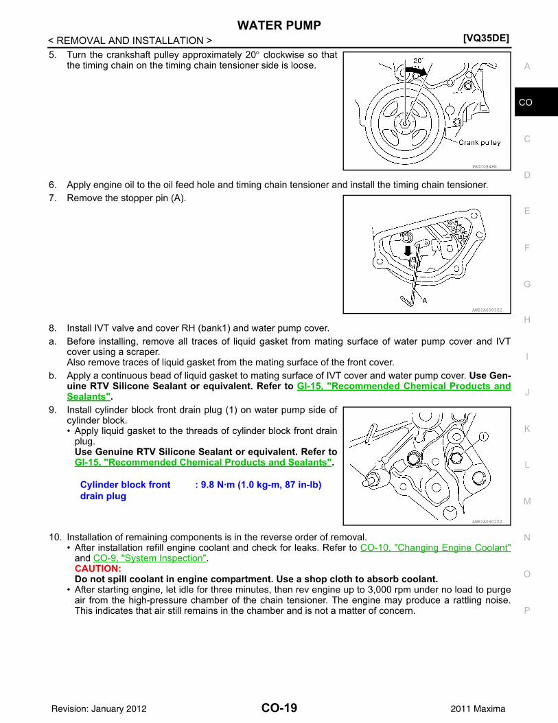
5. Turn the crankshaft pulley approximately 20° clockwise so thatthe timing chain on the timing chain tensioner side is loose.
6. Apply engine oil to the oil feed hole and timing chain tensioner and install the timing chain tensioner.7. Remove the stopper pin (A).
8. Install IVT valve and cover RH (bank1) and water pump cover.a. Before installing, remove all traces of liquid gasket from mating surface of water pump cover and IVT
cover using a scraper.Also remove traces of liquid gasket from the mating surface of the front cover.
b. Apply a continuous bead of liquid gasket to mating surface of IVT cover and water pump cover. Use Gen-uine RTV Silicone Sealant or equivalent. Refer to GI-15, "Recommended Chemical Products andSealants".
9. Install cylinder block front drain plug (1) on water pump side ofcylinder block.• Apply liquid gasket to the threads of cylinder block front drain
plug. Use Genuine RTV Silicone Sealant or equivalent. Refer toGI-15, "Recommended Chemical Products and Sealants".
10. Installation of remaining components is in the reverse order of removal.• After installation refill engine coolant and check for leaks. Refer to CO-10, "Changing Engine Coolant"
and CO-9, "System Inspection".CAUTION:Do not spill coolant in engine compartment. Use a shop cloth to absorb coolant.
• After starting engine, let idle for three minutes, then rev engine up to 3,000 rpm under no load to purgeair from the high-pressure chamber of the chain tensioner. The engine may produce a rattling noise.This indicates that air still remains in the chamber and is not a matter of concern.
PBIC0848E
AWBIA0905ZZ
Cylinder block front drain plug
: 9.8 N·m (1.0 kg-m, 87 in-lb)
AWBIA0902ZZ
CO-19Revision: January 2012 2011 Maxima
[VQ35DE]THERMOSTAT AND THERMOSTAT HOUSING
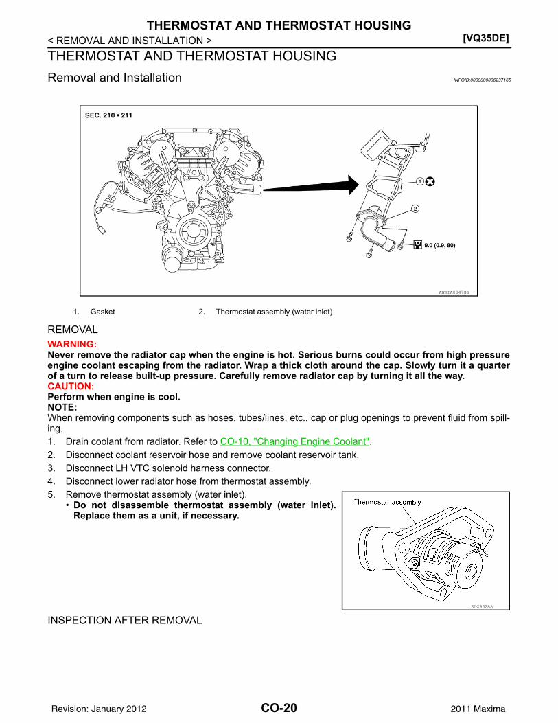
< REMOVAL AND INSTALLATION >THERMOSTAT AND THERMOSTAT HOUSINGRemoval and Installation INFOID:0000000006237165
REMOVALWARNING:Never remove the radiator cap when the engine is hot. Serious burns could occur from high pressureengine coolant escaping from the radiator. Wrap a thick cloth around the cap. Slowly turn it a quarterof a turn to release built-up pressure. Carefully remove radiator cap by turning it all the way.CAUTION:Perform when engine is cool.NOTE:When removing components such as hoses, tubes/lines, etc., cap or plug openings to prevent fluid from spill-ing.1. Drain coolant from radiator. Refer to CO-10, "Changing Engine Coolant".2. Disconnect coolant reservoir hose and remove coolant reservoir tank. 3. Disconnect LH VTC solenoid harness connector.4. Disconnect lower radiator hose from thermostat assembly.5. Remove thermostat assembly (water inlet).
• Do not disassemble thermostat assembly (water inlet).Replace them as a unit, if necessary.
INSPECTION AFTER REMOVAL
1. Gasket 2. Thermostat assembly (water inlet)
AWBIA0847GB
SLC962AA
CO-20Revision: January 2012 2011 Maxima
THERMOSTAT AND THERMOSTAT HOUSING[VQ35DE]
C
D
E
F
G
H
I
J
K
L
M
A
O
N
P
O
< REMOVAL AND INSTALLATION >
C
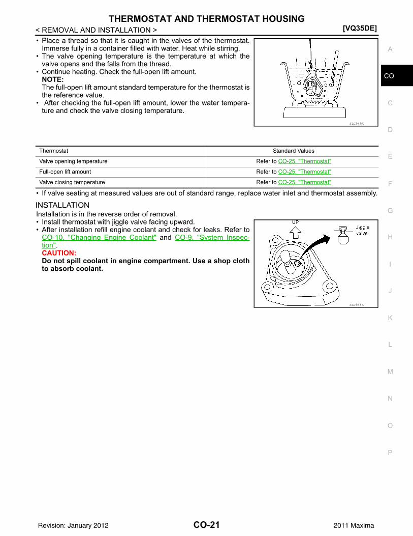
• Place a thread so that it is caught in the valves of the thermostat.Immerse fully in a container filled with water. Heat while stirring.
• The valve opening temperature is the temperature at which thevalve opens and the falls from the thread.
• Continue heating. Check the full-open lift amount.NOTE:The full-open lift amount standard temperature for the thermostat isthe reference value.
• After checking the full-open lift amount, lower the water tempera-ture and check the valve closing temperature.
• If valve seating at measured values are out of standard range, replace water inlet and thermostat assembly.
INSTALLATIONInstallation is in the reverse order of removal.• Install thermostat with jiggle valve facing upward.• After installation refill engine coolant and check for leaks. Refer to
CO-10, "Changing Engine Coolant" and CO-9, "System Inspec-tion".CAUTION:Do not spill coolant in engine compartment. Use a shop clothto absorb coolant.
SLC949A
Thermostat Standard Values
Valve opening temperature Refer to CO-25, "Thermostat"
Full-open lift amount Refer to CO-25, "Thermostat"
Valve closing temperature Refer to CO-25, "Thermostat"
SLC948A
CO-21Revision: January 2012 2011 Maxima
[VQ35DE]WATER OUTLET AND WATER PIPING
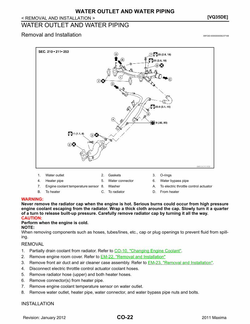
< REMOVAL AND INSTALLATION >WATER OUTLET AND WATER PIPINGRemoval and Installation INFOID:0000000006237166
WARNING:Never remove the radiator cap when the engine is hot. Serious burns could occur from high pressureengine coolant escaping from the radiator. Wrap a thick cloth around the cap. Slowly turn it a quarterof a turn to release built-up pressure. Carefully remove radiator cap by turning it all the way.CAUTION:Perform when the engine is cold.NOTE:When removing components such as hoses, tubes/lines, etc., cap or plug openings to prevent fluid from spill-ing.
REMOVAL1. Partially drain coolant from radiator. Refer to CO-10, "Changing Engine Coolant".2. Remove engine room cover. Refer to EM-22, "Removal and Installation"3. Remove front air duct and air cleaner case assembly. Refer to EM-23, "Removal and Installation".4. Disconnect electric throttle control actuator coolant hoses.5. Remove radiator hose (upper) and both heater hoses.6. Remove connector(s) from heater pipe.7. Remove engine coolant temperature sensor on water outlet.8. Remove water outlet, heater pipe, water connector, and water bypass pipe nuts and bolts.
INSTALLATION
1. Water outlet 2. Gaskets 3. O-rings4. Heater pipe 5. Water connector 6. Water bypass pipe7. Engine coolant temperature sensor 8. Washer A. To electric throttle control actuatorB. To heater C. To radiator D. From heater
AWBIA1014GB
CO-22Revision: January 2012 2011 Maxima

WATER OUTLET AND WATER PIPING[VQ35DE]
C
D
E
F
G
H
I
J
K
L
M
A
O
N
P
O
< REMOVAL AND INSTALLATION >
C
1. Installation is in the reverse order of removal.• Securely insert each hose, and install a clamp at a position where it does not interfere with the pipe
bulge.CAUTION:Do not reuse gaskets.
• When inserting heater pipe and water bypass pipe into water connector, apply neutral detergent to newO-rings.CAUTION:Do not reuse O-rings.
• After installation refill engine coolant and check for leaks. Refer to CO-10, "Changing Engine Coolant"and CO-9, "System Inspection".
CO-23Revision: January 2012 2011 Maxima
[VQ35DE]COOLING FAN
< UNIT DISASSEMBLY AND ASSEMBLY >
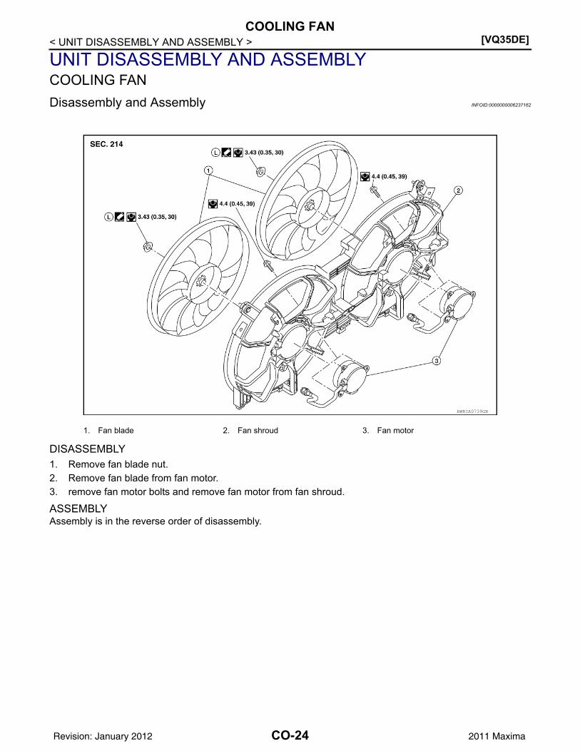
UNIT DISASSEMBLY AND ASSEMBLYCOOLING FANDisassembly and Assembly INFOID:0000000006237162
DISASSEMBLY1. Remove fan blade nut.2. Remove fan blade from fan motor.3. remove fan motor bolts and remove fan motor from fan shroud.
ASSEMBLYAssembly is in the reverse order of disassembly.
AWBIA0739GB
1. Fan blade 2. Fan shroud 3. Fan motor
CO-24Revision: January 2012 2011 Maxima
SERVICE DATA AND SPECIFICATIONS (SDS)[VQ35DE]
C
D
E
F
G
H
I
J
K
L
M
A
O
N
P
O
< SERVICE DATA AND SPECIFICATIONS (SDS)
C
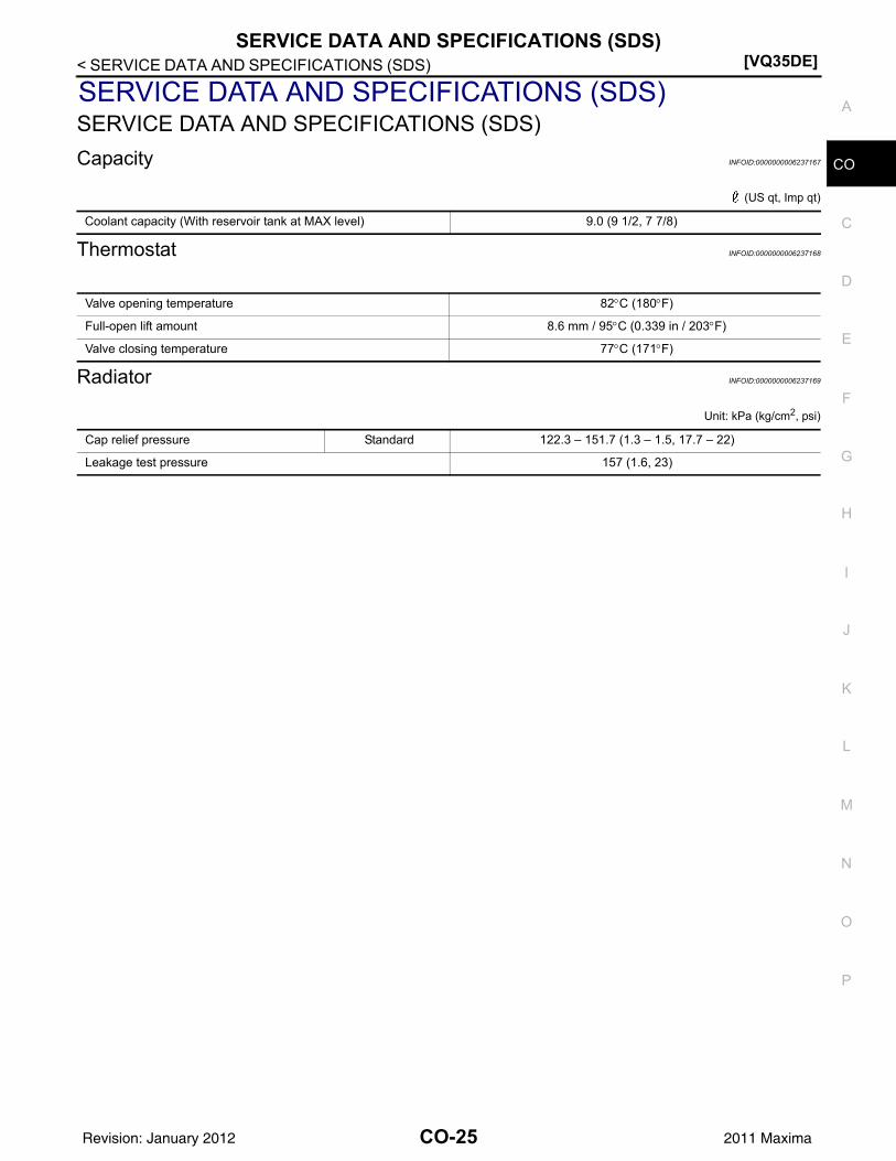
SERVICE DATA AND SPECIFICATIONS (SDS)SERVICE DATA AND SPECIFICATIONS (SDS)Capacity INFOID:0000000006237167
(US qt, Imp qt)
Thermostat INFOID:0000000006237168
Radiator INFOID:0000000006237169
Unit: kPa (kg/cm2, psi)
Coolant capacity (With reservoir tank at MAX level) 9.0 (9 1/2, 7 7/8)
Valve opening temperature 82°C (180°F)
Full-open lift amount 8.6 mm / 95°C (0.339 in / 203°F)
Valve closing temperature 77°C (171°F)
Cap relief pressure Standard 122.3 – 151.7 (1.3 – 1.5, 17.7 – 22)
Leakage test pressure 157 (1.6, 23)
CO-25Revision: January 2012 2011 Maxima