eng swap instructions - buggiesunlimited.com...installation instructions rear body removal remove...
TRANSCRIPT
TOOLSNote: Because of the extensive list of tools required for this kit installation, refer to the steps below to determine what tools will be required.
INSTALLATION INSTRUCTIONSRear Body Removal
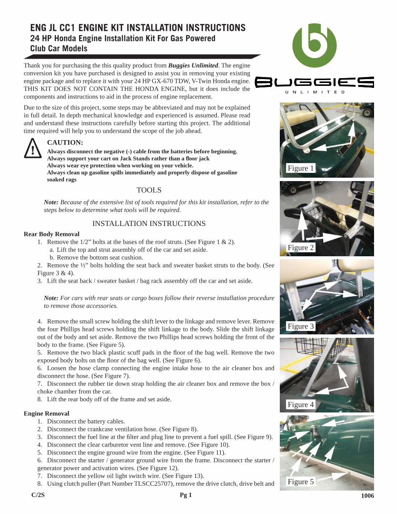
Remove the 1/2” bolts at the bases of the roof struts. (See Figure 1 & 2).Lift the top and strut assembly off of the car and set aside.Remove the bottom seat cushion.
Remove the ½” bolts holding the seat back and sweater basket struts to the body. (See Figure 3 & 4).
Lift the seat back / sweater basket / bag rack assembly off the car and set aside.
Note: For cars with rear seats or cargo boxes follow their reverse installation procedure to remove those accessories.
Remove the small screw holding the shift lever to the linkage and remove lever. Remove the four Phillips head screws holding the shift linkage to the body. Slide the shift linkage out of the body and set aside. Remove the two Phillips head screws holding the front of the body to the frame. (See Figure 5).
Remove the two black plastic scuff pads in the fl oor of the bag well. Remove the two exposed body bolts on the fl oor of the bag well. (See Figure 6).
Loosen the hose clamp connecting the engine intake hose to the air cleaner box and disconnect the hose. (See Figure 7).
Disconnect the rubber tie down strap holding the air cleaner box and remove the box / choke chamber from the car.
Lift the rear body off of the frame and set aside.
Engine RemovalDisconnect the battery cables.Disconnect the crankcase ventilation hose. (See Figure 8).Disconnect the fuel line at the fi lter and plug line to prevent a fuel spill. (See Figure 9).Disconnect the clear carburetor vent line and remove. (See Figure 10).Disconnect the engine ground wire from the engine. (See Figure 11).Disconnect the starter / generator ground wire from the frame. Disconnect the starter /
generator power and activation wires. (See Figure 12).Disconnect the yellow oil light switch wire. (See Figure 13).Using clutch puller (Part Number TLSCC25707), remove the drive clutch, drive belt and
1.a.b.
2.
3.
4.
5.
6.
7.
8.
1.2.3.4.5.6.
7.8.
ENG JL CC1 ENGINE KIT INSTALLATION INSTRUCTIONS24 HP Honda Engine Installation Kit For Gas Powered Club Car Models
Thank you for purchasing the this quality product from Buggies Unlimited. The engine conversion kit you have purchased is designed to assist you in removing your existing engine package and to replace it with your 24 HP GX-670 TDW, V-Twin Honda engine. THIS KIT DOES NOT CONTAIN THE HONDA ENGINE, but it does include the components and instructions to aid in the process of engine replacement.
Due to the size of this project, some steps may be abbreviated and may not be explained in full detail. In depth mechanical knowledge and experienced is assumed. Please read and understand these instructions carefully before starting this project. The additional time required will help you to understand the scope of the job ahead.
CAUTION: Always disconnect the negative (-) cable from the batteries before beginning. Always support your cart on Jack Stands rather than a fl oor jack Always wear eye protection when working on your vehicle. Always clean up gasoline spills immediately and properly dispose of gasoline soaked rags
Figure 1
Figure 2
Figure 3
Figure 4
Figure 5
Pg 1 1006C/2S

Jack Shaft & Drive Belt InstallationInsert the Jackshaft through the bearings in the Engine Mount. The shaft is installed
from passenger side of the car to driver side. (See Figure 30).Drive shaft through bearings until the tapered clutch end rests against the bearing face.On the driver’s side of the car, slide the Jackshaft Collar over the Jackshaft and seat it
against the bearing face. (See Figure 31).Install the Jackshaft pulley inner and outer hubs.
1. Insert Key into keyway. (See Figure 32)2. Slide outer hub onto shaft with threaded hole facing out. (See Figure 33)Slide inner hub onto shaft, over key, and tighten set screw. (See Figure 34)Align the non threaded holes on the inner hub with the threaded holes on the outer
hub. Thread the supplied black fasteners into the outer hub until they are hand tight. (See Figure 35). Then follow the pulley manufacturer’s instructions (in the pulley box) to torque these three bolts.
Should You Need To Remove The PulleysRemove bolts from outer hub.Thread the bolts into the threaded holes on the inner hubTighten the bolts into the outer face of the inner hub in an alternating pattern to push
the two hubs apart.Loosen the set screw and remove the hub and pulley.
Note: Be sure to tighten all three hub mounting bolts together in an alternating fash-ion. This ensures the hubs are seated evenly. Failure to do so can cause the mounting bolts to break when attempting to remove hubs. Also be careful not to over tighten hub mounting bolts as this may cause the bolts to break upon removal as well.
Install Crankshaft Pulley inner and outer hubs and ensure they are aligned with the jack-shaft pulley. (See Figure 36).
Note: In order to get the Crankshaft Pulley hubs to clear the frame, it may be neces-sary to unbolt the Engine Drop Bracket from the front of the engine tray, remove it, and lower the engine slightly.
Place a 5/16” X 18 X 1” bolt through the now unused bolt hole on the driver’s side of the engine tray. Install the Tensioner Assembly over this bolt and lightly fasten with a 5/16” X 18 locknut. (See Figure 37)
Install the Drive Belt over both the Crankshaft and Jackshaft pulleys and around the Idler Pulley.
Press down on the Tensioner Arm to tighten the belt and secure the Tensioner with a 5/16” X 18 X 1” bolt, washer, and lock nut. (See Figure 38)
Completely tighten both Tensioner Arm bolts.Check that the Drive Belt is properly centered on all three pulleys. If not remove tension
from the belt and loosen either the Crankshaft or Jackshaft pulleys. Adjust as necessary.Install the OEM drive clutch onto the passenger’s side of the Jackshaft. Install the OEM
drive belt onto the driven and drive clutches. (See Figure 39)
Note: If the belt does not fi t properly, loosen the four bolts securing the engine assem-bly to the engine tray, slide the assembly to the desired position, and torque the engine mounting bolts.
Note: Check to ensure that the driver’s side brake cable will not rub against the Crank-shaft Pulley. To provide adequate clearance, it may be necessary to remove the wire bracket holding the cable to the frame. Also check that the cable is properly secured with e-clips at the rear drums and under the frame near the brake linkage. If the cable is not properly connected it will fl ex under braking and may rub on the Crankshaft Pul-ley.
Installing the Wiring Harness
1.
2.3.
4.a.b.c.d.
a.b.c.
d.
5.
6.
7.
8.
9.10.
11.
Figure 12
Figure 13
Figure 14
Figure 15
Figure 16
Figure 17
Pg 3 1205

Using a ¼” bit, drill two holes and mount the alternator regulator as shown using the supplied 1/4” X 20 X 1 1/4” bolts and locknuts. (See Figure 40)
Plug in the regulator wire harness. Run the harness around the side of the engine above the drive clutch. (See Figure 41)
Unbolt the 10 mm bolt on the engine case. Attach the ring terminal for the alternator regulator and the ring terminal for the engine ground strap to this bolt and reinstall as shown. (See Figure 42)
Connect the two gray wires from the alternator harness to the two gray alternator output wires located beneath the starter. (See Figure 43)
Set the white wire aside.Install the blue fuel cut solenoid wire to the small post on the ignition solenoid as shown.
(This post will have the blue key switch wire already connected to it) (See Figure 44)Run the wire out of the solenoid box, around to the engine, and connect it to the black
and yellow wire coming out from under the air cleaner box on the Honda engine.
Note: The fuel cut solenoid will be activated when the key is in the ‘on’ position. As such, leaving the vehicle with the key turned ‘on’ and the engine off for extended periods of time will drain the battery.
Relocate the factory wire harness around the solenoid box to the front of the engine com-partment as shown. (See Figure 45)
Connect to white and red factory ignition kill wire to the black and red ignition kill wire coming out from behind the fan shroud on the Honda Engine.
The yellow oil pressure wire and pink starter/generator activation wire will no longer be used and should be secure out of the way.
Cut the ring terminal off the end of the 6 ga. white starter cable.Strip the end of the starter cable and crimp or solder the supplied ring terminal to the
cable.Secure the starter cable to the positive post on the starter using a 12 mm wrench. (See
Figure 46)Remove the 5 amp ignition fuse from the solenoid box and replace with the supplied 30
amp fuse.Cut away the rubber mat to install the fl oor mounted starter switch as shown. (See Figure
47)Install the supplied Ignition Harness by running the wires as follows:
The two red wires with small ring ends are run inside the frame I-Beams along with the OEM harness to the fl oor switch. (See Figure 48)
The ring end on the yellow wire is connected to large post of the ignition solenoid on top of the white starter cable. (See Figure 44)
The ring end on the red wire (with fuse holder) is connected to battery positive. (See Figure 49)
The butt terminal on the red battery positive wire is connected to the white wire com-ing from the alternator harness.
The red wire with the female spade connector is attached to the starter solenoid. (See Figure 46)
The relay connector on the end of the harness is run along the body support of the frame and secured to the frame with #10 hardware as shown. (See Figure 50)
Connect the black ground wire to the frame using the relay connector mounting hard-ware. (See Figure 51)
Plug the supplied relay into the relay connector.
Note: When mounting the relay connector, make sure that it is not mounted too closely to the exhaust. Excessive heat can melt the plastic relay casing.
Installing the Fuel LineRemove the air cleaner box lid on top of the Honda engine.Remove the air cleanerRemove the two 10 mm and two 8 mm bolts that hold the air cleaner box to the engine.
(See Figure 52)With the air cleaner box off, remove the fuel line from the end of the fuel fi lter. (See
1.
2.
3.
4.
5.6.
7.
8.
6.
7.
8.9.
10.
11.
12.
13.a.
b.
c.
d.
e.
f.
g.
14.
1.2.3.
4.
Figure 18
Figure 19
Figure 20
Figure 21
Figure 22
Figure 23
Pg 4 1205
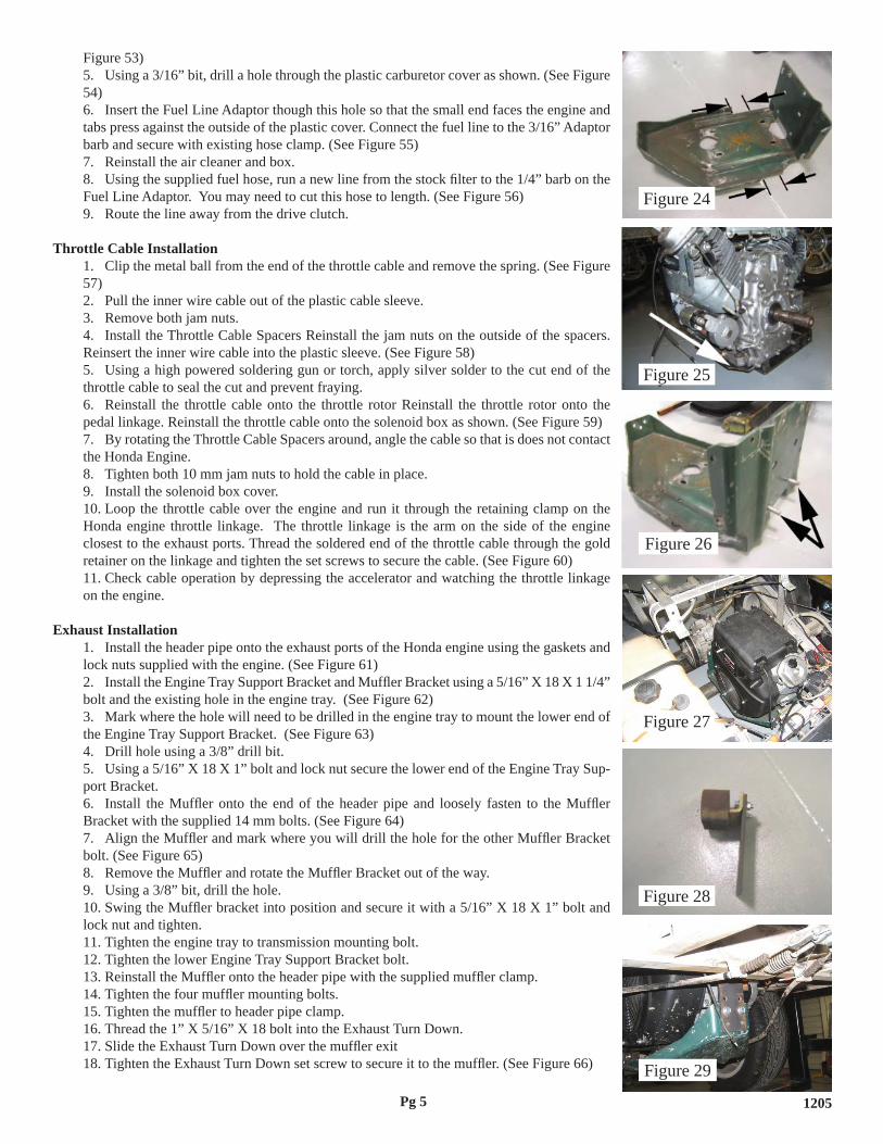
Figure 53)Using a 3/16” bit, drill a hole through the plastic carburetor cover as shown. (See Figure
54)Insert the Fuel Line Adaptor though this hole so that the small end faces the engine and
tabs press against the outside of the plastic cover. Connect the fuel line to the 3/16” Adaptor barb and secure with existing hose clamp. (See Figure 55)
Reinstall the air cleaner and box.Using the supplied fuel hose, run a new line from the stock fi lter to the 1/4” barb on the
Fuel Line Adaptor. You may need to cut this hose to length. (See Figure 56)Route the line away from the drive clutch.
Throttle Cable InstallationClip the metal ball from the end of the throttle cable and remove the spring. (See Figure
57)Pull the inner wire cable out of the plastic cable sleeve.Remove both jam nuts.Install the Throttle Cable Spacers Reinstall the jam nuts on the outside of the spacers.
Reinsert the inner wire cable into the plastic sleeve. (See Figure 58)Using a high powered soldering gun or torch, apply silver solder to the cut end of the
throttle cable to seal the cut and prevent fraying.Reinstall the throttle cable onto the throttle rotor Reinstall the throttle rotor onto the
pedal linkage. Reinstall the throttle cable onto the solenoid box as shown. (See Figure 59)By rotating the Throttle Cable Spacers around, angle the cable so that is does not contact
the Honda Engine.Tighten both 10 mm jam nuts to hold the cable in place.Install the solenoid box cover.Loop the throttle cable over the engine and run it through the retaining clamp on the
Honda engine throttle linkage. The throttle linkage is the arm on the side of the engine closest to the exhaust ports. Thread the soldered end of the throttle cable through the gold retainer on the linkage and tighten the set screws to secure the cable. (See Figure 60)
Check cable operation by depressing the accelerator and watching the throttle linkage on the engine.
Exhaust InstallationInstall the header pipe onto the exhaust ports of the Honda engine using the gaskets and
lock nuts supplied with the engine. (See Figure 61)Install the Engine Tray Support Bracket and Muffl er Bracket using a 5/16” X 18 X 1 1/4”
bolt and the existing hole in the engine tray. (See Figure 62) Mark where the hole will need to be drilled in the engine tray to mount the lower end of
the Engine Tray Support Bracket. (See Figure 63)Drill hole using a 3/8” drill bit.Using a 5/16” X 18 X 1” bolt and lock nut secure the lower end of the Engine Tray Sup-
port Bracket.Install the Muffl er onto the end of the header pipe and loosely fasten to the Muffl er
Bracket with the supplied 14 mm bolts. (See Figure 64)Align the Muffl er and mark where you will drill the hole for the other Muffl er Bracket
bolt. (See Figure 65)Remove the Muffl er and rotate the Muffl er Bracket out of the way.Using a 3/8” bit, drill the hole.Swing the Muffl er bracket into position and secure it with a 5/16” X 18 X 1” bolt and
lock nut and tighten.Tighten the engine tray to transmission mounting bolt.Tighten the lower Engine Tray Support Bracket bolt.Reinstall the Muffl er onto the header pipe with the supplied muffl er clamp.Tighten the four muffl er mounting bolts.Tighten the muffl er to header pipe clamp.Thread the 1” X 5/16” X 18 bolt into the Exhaust Turn Down.Slide the Exhaust Turn Down over the muffl er exitTighten the Exhaust Turn Down set screw to secure it to the muffl er. (See Figure 66)
5.
6.
7.8.
9.
1.
2.3.4.
5.
6.
7.
8.9.10.
11.
1.
2.
3.
4.5.
6.
7.
8.9.10.
11.12.13.14.15.16.17.18.
Figure 24
Figure 25
Figure 26
Figure 27
Figure 28
Figure 29
Pg 5 1205

starter / generator belt. (See Figure 14). Remove three 7/16” bolts holding the starter / generator pulley to the back of the clutch
and remove the pulley. (See Figure 15).Remove the brackets holding the ignition kill wire and throttle cable. (See Figure 16).Disconnect the white and red ignition kill wire. (See Figure 17).Pull the entire wiring harness away from the engine and set aside. Disconnect the throttle cable from the governor linkage by removing the e-clip holding
the throttle cable to the mount bracket. Remove throttle cable and remove throttle cable bracket from transaxle. (See Figure 18).
Remove solenoid box cover by removing the single retaining screw in the top. Loosen both 10 mm jam nuts holding the throttle cable to the solenoid box. Remove the
C-clip holding the plastic throttle rotor to the pedal linkage. Remove the rotor, disconnect, and remove the throttle cable and set everything aside. (See Figure 19).
Loosen the ¾” jam nuts holding the shifter cable to the transaxle. Disconnect the shifter cable from the transmission and set aside. Loosen the clamp holding the governor linkage on the transaxle. (See Figure 20).
Remove the governor linkage from the transaxle, remove the governor cable mount bracket, and set aside.
Support the engine tray with a jack. Remove the six 14 mm engine to transmission nuts and bolts. (See Figure 21).Remove the two ½” bolts holding the snubber to the engine tray and set the snubber
aside. (See Figure 22).Carefully lower the engine down and away from the transmission to slide it free from the
mounting studs.
CAUTION: Use caution when removing the engine from the car, it is recommended to have two or more people for this step to prevent dropping and damaging the engine, personal injury, or both.
With the engine and mount tray out of the car, remove the 14 mm nuts and 13 mm bolts holding the engine to the tray and set the engine aside. Remove the ½” bolts connecting the support brackets to the engine tray and discard these brackets. (See Figure 23).
Preparation and Honda Engine installationCut approximately 3” from each side of the engine tray as shown. (See Figure 24).Reuse the four 13 mm engine mount bolts to secure the Honda V-Twin to the Engine
Mount supplied in the kit. (See Figure 25).
Note: The exhaust ports of the Honda engine face the side of the Engine Mount with the angular relief cut.
Install the two lower engine tray to transmission mounting bolts (See Figure 26).Bolt the Honda V-Twin / Engine Mount assembly to the modifi ed engine tray using the
four supplied 8 MM bolts and fender washers.Lift the car and support with jack stands.Raise the engine assembly into position from under the car.
CAUTION: The Honda engine assembly is more than twice as heavy as the stock as-sembly. Use caution when lifting the engine into the car, it is STRONGLY recommended to have two or more people for this step to prevent dropping and damaging the engine, personal injury, or both.
Secure the engine assembly to the transmission with remaining engine to transmission mounting bolts and nuts. (See Figure 27).
Bolt the snubber to the Engine Drop Bracket with the existing snubber bolts. (See Figure 28).
Secure the Engine Drop Bracket to the front of the engine tray using the provided 5/16” X 18 X 1 ½” bolts. (See Figure 29).
If the snubber does not rest securely in the frame, loosen the axle u-bolts to allow the entire drive train assembly to rotate slightly until the snubber is properly seated.
10.
11.12.13.14.
15.16.
17.
18.
19.20.21.
22.
24.
1.2.
3.4.
5.6.
7.
8.
9.
10.
Figure 6
Figure 7
Figure 8
Figure 9
Figure 10
Figure 11
Pg 2 1205

CAUTION: Do not over tighten the set screw as you can strip the threads on the turn down. If you do destroy the threads, simply drill and tap another hole for the set screw.
Instal heat shield to muffl er. (See fi gure 67)
Choke Cable InstallationTake out the three 1/4” screws to remove the choke button from the rear car body.Install the Choke Cable Plate onto the body with the supplied #10 hardware. (See Figure
68)Reinstall the rear body onto the car. Installation is the reverse of steps on page 1.Slide the Choke Cable through the opening in the Choke Cable Plate until the back of
the pull lever rests against the plate. Secure to the plate with the supplied 9/16” X 18 nut. (See Figure 69)Route the Choke Cable over the exhaust through the retaining clamp and connect it to
the choke linkage on the Honda engine. (See Figure 70)Tighten both linkage set screws and verify Choke Cable operation.
Engine StartupCheck the engine compartment to verify that no wires or cable are contacting the exhaust
or any moving parts. Secure any loosing wiring, cables, or hoses with clamps.Fill the engine with oil.Verify that the OEM spark plugs have been replaced with NGK BPR2ES plugs.
Note: If the factory installed spark plugs are not NGK’s they will need to be replaced per the Honda Technical Service Bulletin. The OEM plug will foul quickly and cause extremely poor engine performance.
Reconnect the battery.Use a jack to lift the rear wheels off the ground.Put the car into gear and turn the key switch to the ‘on’ position.Verify that the fuel cut solenoid under the air cleaner box clicks.Depress the Ignition Floor Switch and verify that the Ignition Harness relay clicks.Double-check throttle and choke linkages for proper movement.In order to engage the starter, the Ignition Floor Switch must be held down as the accel-
erator is depressed. Have an assistant nearby as it may be diffi cult to pull the Choke Cable, while holding the Ignition Floor Switch, and pressing on the accelerator.
Verify that the Honda engine will turn over and start.Once the engine has started, release the Ignition Floor Switch. While the engine is run-
ning, ignition is completely controlled by the accelerator pedal.
Note: If the engine will not start, double check all electrical connections and make sure that a gear has been selected. If the engine will crank but not start, make sure the choke and throttle linkages are connected properly and that the engine is getting fuel.
Finish reinstalling the remainder of the body, seat, and top components.Test-drive the vehicle, checking for leaks and smooth operation.
Note: If the engine will start and run fi ne under no load, but will buck and stumble while driving, make sure the spark plugs have been replaced.
Note: If the take off speed is very abrupt or the engine will not rev to maximum RPM, check the adjustment of the throttle cable at the linkage. Adjustment of the throttle stop screw and position of the cable will fi ne tune the throttle response characteristics of the engine.
Extra Throttle AdjustmentYou will notice that the factory DS throttle linkage does not provide enough throw to operate the Honda throttle from 0-100%. By connecting the cable in the OEM position on the Honda engine, you must either tune for low end drivability or top end throttle.
19.
1.2.
3.4.
5.6.
7.
1.
2.3.
4.5.6.7.8.9.10.
11.12.
13.14.
Figure 30
Figure 31
Figure 32
Figure 33
Figure 34
Figure 35
Pg 6 1205

However, by relocating the throttle cable connector further towards the center of the Honda throttle rotor it is possible to adapt the DS linkage to provide 0-100% throttle on the Honda engine.
The DS throttle cable moves ¾” from 0-100% throttle. You will need to fi nd the spot on the Honda throttle rotor that is displaced ¾” when the Honda engine is moved from 0-100% throttle. That spot is ¾” from the Honda throttle rotor pivot and is shown in Figure 71. Mark this spot and drill a 17/64” hole. Remove the e-clip off of the gold throttle cable connector and remove the connector from the throttle rotor. Reinstall the connector into the new hole and secure with the e-clip. You will now be able to enjoy full throttle control of the Honda engine with your OEM Club Car throttle linkage.
DISCLAIMER: Due to the physical requirements of mechanically reversing the engine rota-tion, the OEM drive clutch has been relocated. The new placement puts the bottom third of the clutch below the engine tray and exposes the clutch to potential road hazards. As a result you will need to be aware that carelessly traversing rough or rocky terrain can result in dam-age to your clutch. For general on road use and light to moderate off road use the position of the clutch will not cause problems. If you anticipate severe off road use we strongly recom-mend you install a Buggies Unlimited Accessory Clutch Shield (call for information). This will protect your clutch from impacts. However, Buggies Unlimited is not responsible should you damage your clutch from negligent or reckless driving. Please pay attention while driving to prevent damage to critical drive train components.
Please enjoy your new high power car and drive safely & responsibly. Ensure that all suspen-sion and steering components are healthy and tight, double check the car alignment, check the condition and adjustment of the brakes, etc. It is important for your safety and the safety of others that your car is in good mechanical condition and well maintained when traveling at very high speeds.
INDEMNIFICATION AND INSURANCE AGREEMENT24 HP Honda Engine installation should be performed by a professional. The engine replace-ment kit purchaser assumes sole and entire responsibility for, and shall indemnify and save harmless Mattison Avenue Corporation (d.b.a. Buggies Unlimited), from any and all claim, liability, responsibility, and damage, or any costs or expenses resulting from any loss of life or injuries or claimed injuries to persons or property that may be sustained in connection with the use of any product before or after purchase, including but not limited to high speed motors. The high speed motor purchaser also shall indemnify Mattison Avenue Corporation (d.b.a. Buggies Unlimited) and save Mattison Avenue Corporation (d.b.a. Buggies Unlimited) harmless with respect to any and all liability that may be incurred.
Golf carts are recommended for use only by those aged 16 and older. Golf carts can be espe-cially hazardous to operate. Always remember that riding and alcohol/drugs don’t mix. Never ride on public roads. Never carry more than two passengers (except shuttles and trams). Never engage in stunt driving. Avoid excessive speeds and be particularly careful on diffi cult terrain. Buggies Unlimited reserves the right, at any time, to discontinue or change specifi cations, pric-es, designs, features, models or equipment without notice and without incurring any obligation.
Figure 36
Figure 37
Figure 38
Figure 39
Figure 40
Figure 41
Pg 7 1205

Figure 46 Figure 47
Figure 48 Figure 49 Figure 50
Figure 51
Figure 42
Figure 45
Figure 43 Figure 44
Figure 52 Figure 53
Figure 54 Figure 55 Figure 56
Figure 57 Figure 58 Figure 59
Pg 8 1205

Figure 65
Figure 68
Figure 70
Figure 60 Figure 61 Figure 62
Figure 63 Figure 64
Figure 69
Pg 9 1205
Figure 71
Buggies Unlimited1-888-444-9994
www.buggiesunlimited.com© Copyright 1997-2008 Buggies Unlimited. All Rights Reserved.
Figure 66 Figure 67

Pg 10