energy production with a tubular propeller turbine · energy production with a tubular propeller...
TRANSCRIPT

Energy production with a tubular propeller turbine
I Samora1,2, V Hasmatuchi3, C Münch-Alligné3, M J Franca2, A J Schleiss2, H M Ramos1 1 Civil Engineering Research and Innovation for Sustainability, Instituto Superior Técnico, Av. Rovisco Pais 1, 1049-001 Lisbon, Portugal. 2 Laboratory of Hydraulic Constructions, École Polytecnique Fédérale de Lausanne, GC A3 504 Station 18, CH-1015 Lausanne, Switzerland. 3 University of Applied Sciences and Arts Western Switzerland Valais, School of Engineering, Route du Rawyl 47, CH-1950 Sion, Switzerland.
Abstract. Micro-hydropower is a way of improving the energetic efficiency of existent water systems. In the particular case of drinking water systems, several studies have showed that pressure reducing valves can be by-passed with turbines in order to recover the dissipated hydraulic energy to produce electricity. As conventional turbines are not always cost-effective for power under 20 kW, a new energy converter is studied. A five blade tubular propeller (5BTP), assessed through laboratorial tests on a reduced model with a diameter of 85 mm diameter and a maximal output power of 300 W, is addressed in this work. Having showed promising potential for further development, since global efficiencies of around 60% were observed, the turbine has been further used to estimate the potential for energy production in a real case study. A sub-grid of the drinking water system of the city of Lausanne, Switzerland, has been used to obtain an annual energy production through hourly simulations with several turbines.
1. Introduction The definition of small hydropower (SHP) limits depends on the country. In Europe, hydropower stations with an installed power lower than 10 MW are considered as small power plants whereas the limit reaches 50MW in China. In Switzerland, SHP represents 10% of the hydroelectricity, 77% of this production is performed by the “larger” SHPs, with an installed power between 1 and 10 MW. Nevertheless, the production of micro power stations lower than 300kW is not negligible reaching 9 % of small hydroelectricity [1].
The interest on micro and pico hydropower is increasing nowadays in the context of searching for new opportunities for renewable energy production and improvement of the existent water systems. Nevertheless, the conventional turbines are often not cost-effective for installed power under 10 MW [1]. Other than classical types of turbine, water wheels, hydraulic screws and pumps working in reverse mode are possible alternative technologies for micro and pico hydropower. Even so, to adapt to the variable discharge conditions and low heads which can be involved in micro and pico hydro schemes, research is being carried out for the development of new technologies. State of the art research on new technologies for energy recovery can be divided in three main fields of application: marine/estuary environment, small rivers and pressurized systems. In this work, focus is given to pressurized systems.
28th IAHR Symposium on Hydraulic Machinery and Systems
1411

One of the most promising types of systems for micro hydropower production is the drinking water supply system: The flow rates are guaranteed during most of the hours of the day, although low consumptions may be verified during the night; it is not dependent on the weather; the main components, such as pipes, tanks and valves, already exist [3]; and since the flow is already pressurized, extra chambers are not necessary. The installation of turbines in these systems can also contribute to the control of leakage due to excessive pressure [4], [5]. Moreover, the proximity of the installations to local consumers allow for a decentralized production, minimizing the transmission losses [3]. In this context, the development of a turbine for inline installation in a pressurized pipe adapted to low head operations and relatively small flow discharges is particularly interesting for drinking water supply systems.
The goal of this work is to present the experimental hydraulic characterization (characteristic curves and efficiency) of a micro/pico turbine and to simulate the energy production in a water supply network using this technology.
2. Experimental setup The Five Blade Tubular Propeller (5BTP) was initially developed in Instituto Superior Técnico (IST), in Portugal [1] during the HYLOW Project (2008-2012), under the scope of the EU 7th Framework Program. The concept was developed through CFD modeling [8] and preliminary laboratorial tests [9].
The present work introduces a new reduced scale runner of the 5BTP turbine with a diameter of 85 mm produced in École Polytechnique Fédérale de Lausanne (EPFL), Switzerland. The turbine body was designed and manufactured by the University of Applied Sciences and Arts Western Switzerland in Sion (HES-SO VS). The experiments were conducted in the HES-SO VS universal hydraulic test rig, presented in figure 1, designed for performance tests mainly for small power turbomachines [10] following the IEC 60193 standard recommendations [8].
Figure 1. Experimental setup of the turbine reduced scale model installed on the HES-SO VS test rig.
In figure 2 a sketch along with a photograph of the new runner, made of bronze, installed on the
turbine shaft is presented. As illustrated in figure 3, the runner is coupled to a downstream shaft placed along with the ceramic bearings is a housing with the same external diameter as the runner hub. This main shaft connects the runner to the external permanent magnet generator. Hence the runner in placed upstream from a 45° elbow in order to reduce the flow head losses (compared to a 90° one) and to ensure a uniform distribution of the upstream flow velocity. Four static pressure collectors connected to three absolute (accuracy of ±0.05%) and two differential (accuracy of respectively ±0.1% and ±0.5%)
28th IAHR Symposium on Hydraulic Machinery and Systems
1412

pressure sensors are used. They were placed one upstream from the runner, two immediately upstream and downstream of the runner and a fourth downstream from the first elbow. The discharge was measured with an electromagnetic flowmeter (accuracy of ±0.5%), the water temperature being also monitored. Finally, a torque meter (accuracy of ±1%) and an encoder were used to measure the parameters necessary to the calculation of the mechanical torque.
Figure 2. Reduced scale model of the 5BTP runner (diameter of 85 mm).
Figure 3. 3D CAD view of the full turbine reduced scale model. The hydraulic performance of the turbine was accessed for discharges between 1.4 and 13.5 l/s and
for runner rotation speeds between 50 and 2 750 rpm. For each fixed value of rotation speed, imposed by the generator, the full discharges range was covered, measuring at each step the flow rate, the head, the torque and the rotating speed feedback. The water temperature was kept between 15° and 25°C for all operating points.
3. Search algorithm and case study Once the characteristic curves of the turbine obtained, simulations were performed to access the energy production with the 5BTP in a drinking water supply network. The choice of placement within a network is not, nevertheless, a straightforward problem due to the variability of discharges and redundancy of branches. Moreover, minimum pressure levels have to be ensured in order to guarantee the quality of water supply to the population.
To optimize the placement of turbines in a given network while respecting the pressure restrictions, the algorithm developed in [12] and [13] was applied. This algorithm is based on the simulated annealing process and optimizes the placement of Nt number of turbines defined by the user with the goal of
Q
N, Tmec
H
Ht
P1 P2 P3
28th IAHR Symposium on Hydraulic Machinery and Systems
1413

maximizing the annual energy production – the objective function is given by equation (1). The variable nxxX ,...,1 is the vector of the branches ID corresponding to the location of each turbine for each
iteration.
T
tt XE
Xf
1
)(
1)( (1)
The objective function is presented as the inverse of the total energy produced in the time window T, since the simulated annealing is a minimization process, while the study is a maximization problem. With a time step t of one hour and a time window of one year, the energy was calculated according to the following relation:
nn
Nt
nnt HQgtXE
1
)( (2)
where g is the gravitational acceleration (m/s2), is the water density (kg/m3) and for each n turbine, Qn (m3/s) is the flow rate, Hn (m) is the head, and n is the total efficiency. In each iteration, the flow rate is obtained from the hydraulic state of the network, calculated with the commercial software EPANET 2.0 which is coupled to the algorithm. To simulate the turbines, singular energy drops are used, whose head-loss coefficient is calculated as a function of the turbine characteristic curve.
Updates to this algorithm were added to allow the installation of more than one turbine in each branch and to take into account head losses in the contractions and expansions.
In order to estimate the performance of the 5BTP in a water supply network, simulations in a real case study were performed using the search algorithm. The chosen case study is a sub-grid of the drinking water network of the city of Lausanne. The sub-grid has 335 branches and 312 nodes (see figure 4), corresponding to 17 km of pipes that cover a maximum difference of elevation of 128 m.
Figure 4. Sub-grid and corresponding elevations of the Lausanne drinking water network used as case study.
The network model was provided by eauservice, the municipal drinking water service of Lausanne,
together with five years of hourly flow data measurements of inflow into the grid. These inflows were distributed among the nodes according to the average spatial flow distribution and averaged to monthly patterns of weekdays and weekends/holidays. In average, the hourly inflow into the network is about 124 l/s.
The adopted minimum pressure level was of 30 m, taking into consideration the typical height of buildings in Lausanne.
28th IAHR Symposium on Hydraulic Machinery and Systems
1414
4. Results
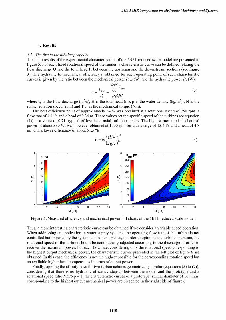
4.1. The five blade tubular propeller The main results of the experimental characterization of the 5BPT reduced scale model are presented in figure 5. For each fixed rotational speed of the runner, a characteristic curve can be defined relating the flow discharge Q and the total head H between the upstream and the downstream sections (see figure 3). The hydraulic-to-mechanical efficiency obtained for each operating point of such characteristic curves is given by the ratio between the mechanical power Pmec (W) and the hydraulic power Ph (W):
gQH
TN
P
P mec
h
mec
60
2
(3)
where Q is the flow discharge (m3/s), H is the total head (m), is the water density (kg/m3) , N is the runner rotation speed (rpm) and Tmec is the mechanical torque (Nm).
The best efficiency point of approximately 64 % was obtained at a rotational speed of 750 rpm, a flow rate of 4.4 l/s and a head of 0.34 m. These values set the specific speed of the turbine (see equation (4)) at a value of 0.71, typical of low head axial turbine runners. The highest measured mechanical power of about 330 W, was however obtained at 1500 rpm for a discharge of 13.4 l/s and a head of 4.8 m, with a lower efficiency of about 51.5 %.
43
21
2gH
Q (4)
Figure 5. Measured efficiency and mechanical power hill charts of the 5BTP reduced scale model.
Thus, a more interesting characteristic curve can be obtained if we consider a variable speed operation. When addressing an application in water supply systems, the operating flow rate of the turbine is not controlled but imposed by the system consumers. Hence, in order to optimize the turbine operation, the rotational speed of the turbine should be continuously adjusted according to the discharge in order to recover the maximum power. For each flow rate, considering only the rotational speed coresponding to the highest output mechanical power, the characteristic curves presented in the left plot of figure 6 are obtained. In this case, the efficiency is not the highest possible for the corresponding rotation speed but an available higher head compensates in terms of output power.
Finally, appling the affinity laws for two turbomachines geometrically similar (equations (5) to (7)), considering that there is no hydrualic efficency step-up between the model and the prototype and a rotational speed ratio Nm/Np = 1, the characteristic curves of a prototype (runner diameter of 165 mm) coresponding to the highest output mechanical power are presented in the right side of figure 6.
28th IAHR Symposium on Hydraulic Machinery and Systems
1415

3
p
m
p
m
p
m
D
D
N
N
Q
Q (5)
22
p
m
p
m
p
m
D
D
N
N
H
H
(6)
53
p
m
p
m
mecp
mecm
D
D
N
N
P
P,
(7)
where m and p subscripts corespond to respectively the model and the prototype, and D represents the runner outer diameter (m).
Figure 6. Characteristic curves of the reduced scale model (left) and of a prototype of 165 mm diameter (right) for maximum mechanical power with variable rotational speed.
4.2. Energy production simulations Using the results from the experimental campaign to represent the turbine performance, in particular the extrapolated characteristic curves at prototype scale (see figure 6), an estimation of the annual production with the 5BTP was made. The search algorithm was used for one, two, three and four turbines considering a generator efficiency of 100%, the global efficiency being given only by the turbine efficiency. In this situation, the results exclude the choice of the electrical equipment.
For each number of turbines to be installed, the algorithm was run twice. With the aim of having also a second best solution, the second run had the restriction of not allowing the solution found in the first run. The results are presented in table 1.
The results present an obvious tendency for the best solution for Nt turbines to be a sequence formed from the best solution with Nt-1 turbines. The best individual placements are, hence, often repeated. Nevertheless, in all solutions the best production is achieved by distributing the turbines in different pipes and not by repeating Nt times the individual placement. This is due to the fact that the installation of turbines will affect the flow rate in each pipe, as the system has new equilibrium.
The selected runner diameters in each location varied from 105 to 175 mm, resulting in maximum power outputs between 1 and 11 kW.
0
50
100
150
200
250
300
350
0
1
2
3
4
5
6
0 5 10 15
Pm
ec(W
)
Hea
d (m
)
Q (l/s)
Head
Mechanical power
750
rpm
1000
rpm
1250
rpm
1500
rpm
0
1000
2000
3000
4000
5000
6000
7000
8000
9000
10000
0
5
10
15
20
0 50 100
Pm
ec(W
)
Hea
d (m
)
Q (l/s)15
00 r
pm 12
50 r
pm
1000
rpm
750
rpm
28th IAHR Symposium on Hydraulic Machinery and Systems
1416

Table 1. Results from the optimization of energy production with one, two, three and four turbines.
N° of turbines
Locations ID Energy (MWh/year)
D (mm)
1 127 54.9 160
142 54.8 160 2 127, 294 57.5 160, 105
142, 294 57.5 160, 105 3 15, 37, 57 80.3 130, 135, 175
15, 37, 128 80.3 130, 135, 175 4 15, 17, 107, 142 95.8 105, 105, 180, 175
15, 17, 107, 156 94.6 105, 105, 180, 175
Finally, the installation of three turbines corresponds to a recovery around 2%, of the energy needed
to pump the average hourly flow incoming into the sub-grid, considering the elevation of the upstream water tank, the elevation of Lake Geneva and a pump with 0.6 of efficiency.
5. Conclusions In this paper, a new pico axial turbine is presented to address the difficulties of installing turbines in water supply networks, under variable flow rates and low heads.
The experimental campaign conducted on the 5BTP reduced scale model with a runner diameter of 85 mm covered a range of discharges between 1.4 and 13.5 l/s and allowed energy recovery with heads bellow 7.5 mwc. The best efficiency point of about 64 % was obtained. The highest measured mechanical power was of 328 W, with a lower efficiency of about 51.5 %. To a prototype of 165 mm, it corresponds to a mechanical power of 9 W. These results can be considered promising when referring to micro/pico machines.
To quantify the energy that the 5BTP could generate in a water supply network, simulations with the experimentally obtained characteristic and efficiency curves extrapolated to the prototype scale were performed in a real case study sub-grid. An optimization algorithm was used to identify the most suitable locations for the installation of one to four turbines in the sub-grid of the drinking water network of the city Lausanne. It was concluded that one turbine would be able to recover around 55 MWh per year.
Acknowledgements This research has been supported by the PhD grant ref. SFRH/BD/51931/2012 issued by FCT under
the IST-EPFL Joint PhD initiative. The authors would like to thank the Swiss Federal Office of Energy for financing the experimental tests of the turbine, and eauservice Lausanne, Switzerland, for the time and data provided to support this work.
28th IAHR Symposium on Hydraulic Machinery and Systems
1417

References [1] OFEN (2013) Global statistics of energy in Switzerland – in french. [2] Wiemann P, Müller G, Senior J (2008) Risk management and resolution strategies for established and novel technologies in the low head small hydropower market. Hidroenergia 2008, Ljubljana. [3] Ramos H, Mello M, De P (2010) Clean power in water supply systems as a sustainable solution: from planning to practical implementation. Water science and technology: water supply, 79(10):24-26. [4] McNabola A, Coughlan P, Corcoran L, Power C, Williams AP, Harris I, Gallagher J, Styles D (2014) Energy recovery in the water industry using micro-hydropower: an opportunity to improve sustainability. Water Policy, 16:168-183. [5] Carravetta A, Giuseppe G, Fecarotta O, Ramos H (2012) Energy production in water distribution networks: A PAT design strategy. Water Resources Management, 26(13): 3947-3959. [6] Weijermars R, Taylor P, Bahn O, Das S R, Wei Y (2012) Review of models and actors in energy mix optimization – can leader visions and decisions align with optimum model strategies for our future energy systems?” Energy Strategy Reviews, 1(1), 5-18. [7] HYLOW (Hydropower converters with very low head differences) (2010) Periodic Report Summary. http://cordis.europa.eu/result/rcn/45354_en.html [8] Ramos H, Borga A, Simão M (2009) New design for low-power energy production in water pipe systems. Water Science and Engineering, 2(4): 69-84. [9] Caxaria G, Mesquita e Sousa D, Ramos H (2011) Small scale hydropower: generator analysis and optimization for water supply systems. World Renewable Energy Congress 2011, Linköping, Sweden. [10] Hasmatuchi V, Botero F, Gabathuler S, Munch C, (2015) Design and control of a new hydraulic test rig for small hydro turbines. The International Journal on Hydropower & Dams, 22(4): 51-60. [11] International Electrotechnical Committee, (1999) Hydraulic Turbines, Storage Pumps and Pump-Turbines - Model Acceptance Tests. International Standard IEC 60193, 2nd Edition. [12] Samora I, Franca M J, Schleiss A J, Ramos H M, (2015) Optimal location of micro-turbines in a water supply network. E-proceedings of the 36th IAHR World Congress, The Hague, Netherlands [13] Samora I, Franca M J, Schleiss A J, Ramos H M, (2016) Simulated annealing in optimization of energy production in a water supply network. Water Resources Management, under review.
28th IAHR Symposium on Hydraulic Machinery and Systems
1418