energy performance of double-skin …etd.lib.metu.edu.tr/upload/107830/index.pdfiii abstract energy...
TRANSCRIPT
ENERGY PERFORMANCE OF DOUBLE-SKIN FAÇADES
IN INTELLIGENT OFFICE BUILDINGS: A CASE STUDY IN GERMANY
A THESIS SUBMITTED TO THE GRADUATE SCHOOL OF NATURAL AND APPLIED SCIENCES
OF THE MIDDLE EAST TECHNICAL UNIVERSITY
BY
AYÇA BAYRAM
IN PARTIAL FULFILLMENT OF THE REQUIREMENTS FOR THE DEGREE OF MASTER OF SCIENCE
IN THE DEPARTMENT OF ARCHITECTURE
SEPTEMBER 2003

Approval of the Graduate School of Natural and Applied Sciences of the Middle East Technical University
_____________________ Prof. Canan Özgen, PhD.
Director
I certify that this thesis satisfies all the requirements as a thesis for the degree of Master of Science.
_____________________ Assoc. Prof. Selahattin Önür, PhD.
Head of Department
This is to certify that we have read this thesis and that in our opinion it is fully adequate, in scope and quality, as a thesis for the degree of Master of Science.
_____________________ Asst. Prof. Soofia Tahira Elias-Özkan, PhD.
Supervisor Examining Committee Members Assoc. Prof. Arda Düzgüneş, PhD. _____________________
Asst. Prof. Soofia Tahira Elias-Özkan, PhD. _____________________
Asst. Prof. Metin Arikan, PhD.
_____________________
Part-time Instr. Erkan Şahmalı _____________________
Raife Ergin _____________________

iii
ABSTRACT
ENERGY PERFORMANCE OF DOUBLE-SKIN FAÇADES
IN INTELLIGENT OFFICE BUILDINGS:
A CASE STUDY IN GERMANY
Bayram, Ayça
M. Sc., Department of Architecture
Supervisor: Asst. Prof. Soofia Tahira Elias Özkan, PhD.
September 2003, 135 pages
The building industry makes up a considerable fraction of world’s energy
consumption. The adverse effects of a growing energy demand such as depletion in
fossil fuel reserves and natural resources hassled the building industry to a search for
new technologies that result in less energy consumption together with the maximum
utilization of natural resources. Energy- and ecology-conscious European countries
incorporated the well-being of occupants while conducting research on innovative
technologies. In view of the fact that double-skin façades offer a healthy and
comfortable milieu for the occupants and use natural resources hence consume less
energy they became a promising invention for all concerns. The analysis of the
performance of the double-skin façades and energy consumption is inconclusive at
this time. However, based upon thermal performance analysis have been done so far,
a double-skin façade perform better and provide some energy reduction, particularly
on the heating side cycle, from a standard double glazed unit wall.

iv
The aim of this study was to examine the relationship between double-skin
façades and building management systems in intelligent office buildings as they
relate to energy efficiency issues thus to find out whether or not the integration of
these systems into intelligent buildings provides optimization in energy performance
and comfort conditions. The building for the case study, which is an intelligent office
building incorporating a double-skin façade was selected as one that promises high
comfort conditions for the occupants with low energy consumption. The working
principles of integrated façade systems, together with their advantages and
disadvantages were investigated by means of the case study. It was concluded that
due to their high initial costs, these systems offer no real advantages for today.
However with the inevitable exhaustion of fossil fuels that is foreseen for the future,
these systems would become an innovative solution in terms of energy conservation.
Keywords: Intelligent Buildings, Double-skin Façade, Double-shell Façade,
Double Façade, Energy Performance, Energy Efficient Building Design.

v
ÖZ
AKILLI OFİS BINALARINDA ÇİFT CEPHELERİN ENERJİ PERFORMANSI
Bayram, Ayça
Yüksek Lisans, Mimarlık Bölümü
Tez Yöneticisi: Yrd. Doç. Dr. Soofia Tahira Elias Özkan
Eylül 2003, 135 sayfa
Devamlı artmakta olan enerji ihtiyacı sonucu oluşan fosil yakıtların ve doğal
kaynakların azalması gibi olumsuz etkiler, dünya enerji tüketimi üzerinde büyük bir
paya sahip olan yapı endüstrisini daha az enerji tüketimini ve doğal kaynaklardan
maksimum düzeyde faydalanmayı sağlayan teknolojiler için bir arayışa
sürüklemiştir. Ekoloji ve enerji duyarlılığına sahip Avrupa ülkeleri yeni teknoloji
araştırmalarını sürdürürken kullanıcıların huzurunu sağlamayı da dikkate almışlardır.
Çift cephe sistemleri bina kullanıcılarına rahat ve sağlıklı bir ortam sunmalarının
yanı sıra doğal kaynaklardan olabildiğince faydalanarak minimum enerji tüketimiyle
kaygıların bir çoğuna cevap verebilecek yeni bir çözüm olma yolunda potansiyele
sahiptir. Bugün için çift cidarlı cephe sistemlerinin enerji performans analizleri kesin
bir sonuç vermemekle birlikte, şu ana kadar yapılmış olan ısıl performans analizleri
çift cidarlı cephe sistemlerinin standart çift cama oranla, özellikle ısıtma açısından
daha iyi performans gösterdiklerini ve belli bir enerji tasarrufu sağladıklarını
göstermektedir.

vi
Bu çalışmada çift cepheler ile bina yönetim sistemleri arasındaki ilişki enerji
performansı açısından incelenmekte ve bu sistemlerin akıllı binalara dahil edilmesi
halinde daha iyi bir enerji performansı sunup sunmadıkları araştırılmaktadır. Örnek
durum incelemesi olarak düşük enerji tüketimiyle kullanıcılarına yüksek konfor
koşulları sunan çift katmanlı cepheye sahip akıllı bir ofis binası ele alınmıştır. Bu tez
örnek bina üzerinden inceleme yaparak bina enerji sistemlerine dahil edilmiş çift
cephe sistemlerinin çalışma prensiplerini avantaj ve dezavantajlarıyla birlikte
sunmaktadır. Yapım aşamasında maliyeti çok yüksek olan bu sistemler şu an için çok
fazla tercih edilmemekle birlikte çok yakın gelecekte yaşanması muhtemel fosil
kaynakların tükenmesiyle oluşacak enerji arayışına bir çözüm olma yolunda
ilerlemektedir.
Anahtar Kelimeler: Akıllı Binalar, Çift Cidarlı Cephe, Çift Kabuklu Cephe,
Çift Cephe, Enerji Performansı, Enerji Etkin Tasarım.

vii
To My Family.
To My Family.
To My Beloved Family To My Family.
To My Family.

viii
ACKNOWLEDGEMENT
I would like to express my sincere thanks and appreciation to Asst. Prof.
Dr. Soofia Tahira Elias-Özkan. This work would not have been possible without her
generous support, persistent guidance and patience.
I am grateful to the entire staff of the Project Department of the
Çuhadaroğlu Aluminum Industry and Trade Co., Inc. for their understanding and
cooperation. Especially to Nelin, Adnan and Özlem for their valuable guidance,
immeasurable support and contribution to my thesis. My special thanks to Ayşin
Türköz for her trust in my work; she was the only one who defended me in difficult
times.
Thanks also to Annette Nasgowitz from Hochtief Project Development
GmbH , Alexander Knirsch and Thomas Auer from Transsolar Energietechnik
GmbH for their help and participation.
I cannot thank enough my family for so generously giving me the time and
space to focus on this work. Also special thanks to my sister Zeynep for her
immeasurable assistance and unshakeable faith in me.
Thanks also to my faithful friends, especially Güzden and Okan, for their
continual support and help.

ix
TABLE OF CONTENTS
ABSTRACT...............................................................................................................iii
ÖZ.................................................................................................................................v
DEDICATION..........................................................................................................vii
ACKNOWLEDGEMENTS....................................................................................viii
TABLE OF CONTENTS..........................................................................................ix
LIST OF TABLES....................................................................................................xii
LIST OF FIGURES.................................................................................................xiii
LIST OF ABBREVIATIONS.........................................................................…..xviii
CHAPTER
1.INTRODUCTION…………………………………………………………..1
1.1 Argument…………………………………………………………………3
1.2 Objectives………………………………………………………………...4
1.3 Methodology……………………………………………………………..4
1.4. Disposition……………………………………………………..…….….6
2. LITERATURE SURVEY….………………………………………….....…8
2.1. Intelligent Buildings….…...…………………………………...………...8
2.2. Historical Development of Intelligent Buildings ……………...........…10
2.3. Integrated Systems in Intelligent Buildings……………....................…13
2.3.1. Information Systems…...………………….…………..............…18
2.3.2. Facilities Management………………………….……..................18
2.4 Façade Design in Intelligent Buildings..………...…………...............…20

x
2.4.1. Façade Typologies.………….....…………......….........................23
2.4.2. Double-skin Façades.…………...…..………......…......................24
3. CASE STUDY: THE HOCHTIEF PRISMA BUILDING……...........…51
3.1. Materials and Methods of the Study……………………………………51
3.2 Introduction….……………………….…................................................52
3.2.1. Building Layout………………..…............................................…54
3.2.2. Façade Composition…………..……………………….............…60
3.2.3. Design Decisions...………….………..................................….…66
3.3. Energy Management Systems……….................................................…68
3.3.1. Winter Operations…………….....…….……..………………..…68
3.3.2. Summer Operations ……………………….........................….…71
3.4. Simulation Study………………………………………………………..73
3.4.1. Simulation Tools…………..…………………………………......74
3.4.2. Results of the Simulations…………...………………………......77
3.5. Cost Analysis…………………………………………………………...81
4. CONCLUSION AND RECOMMENDATIONS…...…...................……84
LITERATURE CITED...…………………….…....................................................89
APPENDICES
A. Comparative analysis of double-skin façades and conventional façades…….….91
B. Cost analysis of double-skin façades and conventional façades…….…………...95
C. Architectural drawings of the case study………..……………..……………..….98
D. Façade composition showing the façade elements and glass types.…..……..…113
E. Configurations of the exterior skin modules of the double-skin façade………...116

xi
F. Images of the Prisma Building...……………..……………….…………..…….125
G. Airflow simulation results………………………………...……………………133

xii
LIST OF TABLES
Table 2.1 Performance criteria for evaluating the integration of systems…………………14 2.2 Expanded outline of critical performance qualities……………………………..16 2.3 Study of air-quality-related illnesses…………………...………….……………21 2.4 Cost analysis of traditional building…………………………………………….47 2.5 Cost analysis of a double-skin façade…………………………………………...47 2.6 Pro and Con arguments on DSFs…………………………………..……………50 3.3 Survey of some conditions for the building simulations…………..……………75 B.1 Deep plan building cost…………………………………………………………96 B.2 Narrow plan building cost………………………………………………………97

xiii
LIST OF FIGURES
Figure 2.1 Models of Building Intelligence ......................................................................... 10
2.2 The IBE model of building intelligence............................................................... 12
2.3 Two Generic Types of Double Façades .............................................................. 25
2.4 Diagram of different multiple skin façades......................................................... 30
2.5 Annual heating and cooling load per unit of floor area for the basic variants and the parameter analysis............................................................................ 31 2.6 Energy consumption quantities for different façade typologies applied on deep plan and narrow plan buildings. ........................................................................ 32 2.7 CO2 Emissions for different façade typologies applied on deep plan and narrow plan buildings................................................................................................. 33 2.8 Buffer System ...................................................................................................... 38
2.9 Business promotion center façade detail.............................................................. 39
2.10 Double skin façade……………………………………………………………..39
2.11 Extracted System............................................................................................... 40
2.12 Exterior view of the Helicon Building….………….…………………………..41 2.13 Cavity of the DSF .............................................................................................. 41
2.14 Story-height double-skin façade of Helicon Building ....................................... 42
2.15 Twin Face system............................................................................................... 43
2.16 The diagonal flowing of air................................................................................ 44
2.17 The composition of the façade…………………………………………………44 2.18 Annual running costs…..………………………………………………………48

xiv
3.1 Model prepared for the competition………………..........…..…...……………..52 3.2 Roof plan of the Prisma Building……………………………………………….53 3.3 Interior view from the atrium showing the bridges……………………………..54 3.4 Interior skin panel modules……………………………...………………………55 3.5 Corner of the double-skin façade showing the winter garden…………………..56 3.6 View from the corner……………………………………………………………56 3.7 Section detail from the cavity…………………………………………………...57 3.8 Double skin façade modules…………………………………………………….58 3.9 Front view of the double skin façade……………………………………………59 3.10 Bottom opening vents controlled by motors electronically……………………60 3.11 Life size mock-up………………...……………………………………………61 3.12 Single glazed glass partition detail………………………………………….…62 3.13 Ground floor with colonnaded corner………………………………………….63 3.14 Steel anchorage inserted in the RC beam carrying the inner pane……….……63 3.15 Interior pane module…………………………………………………………...64 3.16 Winter operation in the building……………………………………….………66 3.17 Schematic drawing of the offices in the side block during winter……….….…67 3.18 Schematic drawing of the offices in the front block during winter…...……….68 3.19 Summer operation in the building……….……………….…………………….69 3.20 Schematic drawing of the office rooms in the side block during summer.….…70 3.21 Schematic drawing of the offices in the front block during summer………..…71 3.22 Principle representation of the ventilation concept during winter…….…….…72

xv
3.23 Principle representation of the ventilation concept during summer…...………73 3.24 Visualization of the light ratios in the atrium under overcast sky conditions….74 3.25 Representation of 1:1 section model.…………………………………..………74 3.26 Double façade temperatures over the height on the southeast side after a 14-day heat period…………………………………………………...………………76 3.27 Temperatures for the southeast offices with statistical and measured weather data……..……………………………………..…………..………………..76 3.28 Temperatures for the southeast offices with statistical and measured weather data………………………………..…………………………………..……77 3.29 Qualitative connections of comfort and costs for HVAC……………………...79 A.1 Comparative fresh air-cooling analysis for different façade typologies…..……91 A.2 Comparative fresh air-heating analysis for different façade typologies..………92 A.3 Comparative space-cooling analysis for different façade typologies.………….93 A.4 Comparative space-heating analysis for different façade typologies…...………94 C.1 Site plan…………………………………………………………………………98 C.2 First floor plan…………………………………………………………………..99 C.3 Second floor plan……………...………………………………………………100 C.4 Third floor plan…………………………………………………………..……101 C.5 Fourth floor plan………………………………………………………….……102 C.6 Fifth floor plan……………………………………………………………...…103 C.7 Sixth floor plan………………………………………………………………...104 C.8 Seventh floor plan……………………………………………………………..105 C.9 Eighth floor plan………………………………………………………………106 C.10 Ninth floor plan………………………………………………………………107
xvi
C.11 Tenth floor plan………………………………………………………………108 C.12 Eleventh floor plan…………………………………...………………………109 C.13 Section through the side block……………...……..…………………………110 C.14 Section through the front block………………………………………………111 C.15 Sections through the double skin façade……………………………………..112 C.16 Sections through the double skin façade……………..………………………113 D.1 Façade composition front view……………………………………………..…114 D.2 Façade composition side views……………………………………………..…115 D.3 Façade composition showing the glass types………………………………….116 E.1 Module with bottom vents……………………………………………………..117 E.2 Module without vents………………………………………………………….118 E.3 Winter garden panel module…………………………………………………..119 E.4 Module with single bottom vent……………………………………………….120 E.5 Module with single top vent…………………………………………………...121 E.6 Module with top opening vents………………………………………………..122 E.7 Module with single bottom opening vent…………………………...…………123 E.8 Grouped vent modules…………………………………………………………124 E.9 Grouped vent modules…………………………………………………………125 F.1 Interior view from the atrium …………………………………………………126 F.2 Exterior view of the Prisma Building …………………………………………127 F.3 Interior view showing the coincidental bridges that connect three blocks to each other………………….…………………………………………………….128 F.4 The cavity of the double skin façade showing the top vents ……….…………129

xvii
F.5 Construction stage of the double skin façade …………………………………130 F.6 Top view of the building looking at the front block…………………...………131 F.7 Top view of the building looking at the side block……………………………132 F.8 Interior view of the building showing the atrium and glass roof ……………...133

xviii
LIST OF ABBREVIATIONS
AFW- Airflow Window
ASHRAE- American Society of Heating, Refrigerating and Air-conditioning
Engineers
BACnet- Building Automation and Control networks
BAS- Building Automation System
BMS- Building Management Systems
BP- British Petroleum
CCMS- Central Control and Monitoring System
CFD- Computational Fluid Dynamics
COMIS- Conjunction of Multizone Air Infiltration Specialist
DSF-Double Skin Façade
EMS- Energy Management System
EMCS- Energy Management and Control System
FMS- Facilities Management System
HVAC-Heating, Ventilating and Air Conditioning
IB- Intelligent Building
IBE- Intelligent Building in Europe
IGU - Insulating Glazing Unit
IT- Information Technology
MSF- Multiple Skin Façade
STS- Shared Tenant Services
SUP- Supply Window
TRNSYS- Transient System Simulation

1
CHAPTER 1.
INTRODUCTION
This study presents a critical discussion of energy performance of double skin
façades in intelligent office buildings. In this chapter are presented the argument and
primary objectives of the study, together with a brief overview of the general
methodology. The chapter concludes with a disposition of the material contained in
remaining chapters.
1.1. Argument
The emergence of the Double Skin Façades (DSF) dates back three quarters of
a century. Rapid development had begun in the1970s, which was identified as the
“oil-crisis era”. Growing concern for energy use following the crisis accelerated
improvements in the glass industry. The glass-manufacturing companies started to
seek new solutions and to discover new materials that might enable buildings to
consume less energy. Together with the inventions in glass products, DSF
technology also gathered momentum. Consciousness of ecology and environment, as
well as the convenience of climatic conditions led European countries to become the
place of origin of DSF technologies. Application of DSFs is wider in Europe than
elsewhere due to cultural, political and regional advantages.
The common use of DSF is in buildings that are exposed to high wind loads,
such as high-rise office buildings, in which the required air exchange can be

2
managed throughout a long period in a natural way. High wind loads do not allow
the occupants to open the windows in high-rise office buildings since the airflow in
the room becomes disturbing due to the higher velocity of the wind at upper floors.
Buildings using this façade technology are mostly intelligent buildings (IB). Their
daylighting and solar gain problems are solved by perforated aluminum Venetian
blinds and vents controlled by micro-mechanisms. The sensors located at different
points send data to a central control point and adjustments are made based on these
feedbacks. IB technology requires a multi disciplinary design, and architectural
design is the starting point for all disciplines that take part in the design stage. An
intelligent building requires intelligence applied at the concept, construction and
operation stages of a project by clients, design consultants, contractors,
manufacturers and facilities managers.
Today, buildings are not simply a combination of stone and glass; rather they
are becoming more like high performance working machines with the developments
in technology. Intelligent buildings can check and control the comfort conditions for
the exterior as well as interior environments appropriately.
There are two claims about DSFs today, neither of which has been proven as
yet. One is the energy efficiency of these systems. Even though DSFs are considered
to be energy efficient façades, there is a lack of corroborating scientific evidence.
Computational fluid dynamics (CFD) calculations that use various numerical
techniques to solve the pollution dispersion, heat transfer, phase change, chemical
reaction and many other associated phenomena are carried out for computer
simulations. There are a large number of parameters that change from region to
region as well as from building to building and these calculations do not enable
concurrently entering all such parameters for these simulations. It is nevertheless
claimed that DSFs provide up to 25-30% energy savings compared to conventional
façades.

3
The second claim is that by reducing heating and cooling loads of the building
it is possible to amortize the initial cost in long-term. Any savings here depend on the
building type and occupancy as well as on regional conditions. Cost analyses show
that the initial cost of the DSFs range from 20% to 300% of conventional façades,
depending on actual façade composition.
Since fossil fuel reserves are being exhausted day by day, what is left should be
used carefully and renewable resources should be utilized as much as possible. In a
study presented by British Petroleum (BP) Statistical Review of World Energy1, it is
indicated that total depletion time of fossil fuel reserves has decreased in 1997 from
42.2 years to 40.9 years; in other words in a period of 40 years we will run out of
fossil fuels. Thus, more attention must be paid to solar energy, which is
environmentally friendly and available just about everywhere on earth, unlike fossil
fuels. Intelligent buildings have the potential that integrates technology and ecology
by using renewable resources such as solar energy instead of fossil fuels with the
help of double skin systems.
Counting from the last decade with the objective of minimizing the energy
consumption of office buildings and maximizing user comfort, various multi-layer
glass façade systems have been developed, the most interesting one of which is the
double-skin façade. Following years after the oil crisis in 1970s, the fully glazed
buildings were criticized by the authorities due to their inefficient energy
consumption. Therefore, the construction industry headed to develop new techniques
such as photosensitive, thermochromic, electrochromic and photochromic glass, and
new coatings such as reflective or selective (Low-E), angular selective and anti-
reflection. With the use of advanced glass techniques, double-skin façades utilize
1 BP Statistical Review of World Energy, June 2003, Retrieved Aug. 05, 2003, http://www.bp.com/files/16/bp_stats/history_1612.pdf
4
solar energy to reduce the energy consumption of the buildings in United States,
which is, 36% of the nation's energy according to Scientific American.
The argument in the study is that, DSF is one of the solutions to reduce energy
consumption that is heating and cooling loads in energy conscious intelligent office
buildings. Despite the disadvantages drawn by the author above, there are still
various benefits, which can bring the buildings aesthetics, transparency, security,
sound reduction, lifecycle impacts, water penetration resistance, occupant
productivity and contact with the environment, and improved office atmosphere with
user control and comfort addition to energy savings. There is an obvious situation
that the DSFs are exposed to be studied and sought whether they are energy efficient
or not, together with the cost analyses to see if they amortize the initial cost in long-
term assessment.
1.2. Objectives
The aim of the study is to find out whether the DSF has an important role in
energy saving for the buildings or not. Energy consumption for heating and cooling
loads for the buildings is directly related with the total glass area since most of the
heat gains and losses occur through the glass surfaces. The concept of the DSF
depends on the stack effect, which is created between two glass screens to remove
the heat from the building in hot seasons or by using the greenhouse effect to warm
up in cold seasons, and this leads the façade to be fully glazed. The point here is to
find out whether the double-skin façades have high thermal performance under
whatever circumstances and what the pros and cons of so-called façades are.
The configuration of the system, sequence of the glass layers is directly related
with the climate. Some studies show that the heating demand of the DSFs is higher
than the single glazed conventional type façades. On the other hand, its function as a
thermal chimney utilizing the stack effect to remove excessive heat in summer
decreases the cooling loads apparently. Furthermore the studies show that as
compared to the conventional façade systems DSFs are credited with a 30%
reduction in energy consumption, providing for natural ventilation even in
skyscrapers and providing valuable noise reduction. They also create a visually
5
transparent architecture that is impossible with conventional curtain wall façades
with similar thermal properties. The objective of the study will be to find out that
whether the DSFs have important contributions to the reduction of energy
consumption. Since the initial costs are very high for DSFs the question will be is it
worthwhile.
The studies done so far cannot give specific results for overall energy
performance of the DSF systems. The study will bring the analyses together and will
try to reach a conclusion about the argument. As well as the relation between the
intelligent building systems and double skin façades will be studied in order to find
out if these systems become more energy efficient when they are incorporated in the
entire operations of the buildings.
1.3. Methodology
The thesis has tried to reach a conclusion by evaluating a case study under the
light of analyses that have been done until now. Prior to doing so, typologies of
double skin façades with different working principles have been discussed through
various buildings regarding their structures; thermal performance analyses have been
surveyed, as well as parameters affecting the performance of double façade systems
have been identified.
The author works under a company named Çuhadaroğlu Aluminum Industry and
Trade Inc. that produce aluminum systems and façades mostly for commercial and
office buildings. The case study was selected specifically as it is one of the projects
that the company has designed between 1999-2001. The architectural drawings,
detail drawings of the DSF system and the images of the building were acquired
from the company. Through the personal interviews with the project director and the
construction site chief of the case study, information about the design stages and the
problems occurred during and after the construction of the building was obtained.
The building layout and the façade composition were both examined through the
drawings and photos and then verified by people who have worked for this project.

6
Cost analysis of the case study was obtained from the charts prepared by the
project director and also from the personal interviews with the associated manager of
the tender department.
Contacts with Annette Nasgowitz from Hochtief Project Development GmbH in
Essen and Alexander Knirsch and Thomas Auer from Transsolar Energietechnik
GmbH in Stuttgart have been set up through e-mails, faxes and phone interviews.
Transsolar Company was the one that developed strategies for energy efficient
design and thermal comfort for the building whereas Hochtief Project Development
established the investment and design decisions and drawn application projects of the
building. Thermal, hydraulic and airflow simulation tests have been done by this
company and gathered in a report named “Termination Report of the Energy
Concept”. All data related with the simulations and thermal performance of the
building and also schematic drawings were attained from this report. Moreover, data
from the e-mails sent by Mr. Knirsch and Mr. Auer in which they answered the
questions asked by the author about the building management systems (BMS) and
performance of the building were used. By doing so, the study have tried to find
answers to the energy related subjects of the building.
1.4. Disposition
The study is presented in four chapters:
Chapter 1 introduces the subject of the study including its argument and
objectives. Along with a concise outline of the general methodology is given the
sources of data captured for the case study. Conclusively with the disposition of
subject matter the ongoing of the thesis is presented.
In the literature survey presented in Chapter 2 this thesis investigates intelligent
buildings by studying their emergence, development phase and technological aspects
together with their contribution to energy savings, ecology and environment. The
author then deals with the energy management issues regarded in intelligent building
design, in cooperation with the double skin façades.
7
Technical aspects, working principles, typologies and thermal performance of double
skin façades are examined. Finally, the study emphasizes the integration of double
skin façades into the intelligent buildings.
The case study presented in Chapter 3, which is an intelligent high-rise office
building incorporating a DSF at one of its three sides located in Frankfurt, is
examined under the light of aforementioned studies and analyses. Including the
location and climatic conditions and with its overall working principle the case study
is a good example to introduce assumptions about the energy performance of double
skin façades that are integrated into the intelligent office buildings.
Finally Chapter 4 concludes the study by evaluating the case study in terms of
its energy performance and concepts defined in the literature survey.

8
CHAPTER 2.
LITERATURE SURVEY
In this chapter, a survey of literature about intelligent buildings; their
development including technical aspects; façade design together with their relation
with building management systems; façade typologies including double skin façades;
DSFs objectives, typologies, performance evaluation as well as parameters affecting
performance and finally a critical review of double skin façades are presented.
2.1. Intelligent Buildings
The term “intelligent building” originated in the early 1980s in the United
States, where it was used to denote buildings with sophisticated telecommunications,
building management and data networking services that provided shared tenant
services (STS) to their occupants. The development of the intelligent buildings (IB)
was closely linked to the growth of information technology (IT) during this period.
Definitions of the intelligent building during this period therefore focused on major
technological systems such as building automation, communications and office
automation. (Harrison et al., 1998)
Even though the expression has been in use for at least 20 years, there is not a
universally acceptable definition of intelligent buildings. One definition, which
resulted from the International Symposium on the Intelligent Building, held in 1985
in Toronto is: "an intelligent building combines innovations, technological or not,
with skilful management, to maximize return on investment.

9
Different information systems constitute the building intelligence. There are
various forms of facilities of these systems. The way they are integrated with each
other designates the intelligence degree. Thus, building intelligence is a continuum of
capabilities provided by a variety of information services or systems. Today most
buildings contain one or more of these information systems to some extend and they
are marketed as intelligent buildings indeed they are "dumb" buildings. (Bernaden
and Neubauer, 1988)
Coggan2 refers to a definition on his web site, which is proposed by the
Intelligent Building Institute "an intelligent building is one that provides a productive
and cost-effective environment through optimization of its four basic elements -
structure, systems, services and management - and the interrelationships between
them. Intelligent buildings help business owners, property managers and occupants
to realize their goals in the areas of cost, comfort, convenience, safety, long-term
flexibility and marketability." An intelligent building must contain technology of
widespread microprocessors that operate internal systems - lighting; heating,
ventilating and air conditioning (HVAC); power; vertical transportation; fire and life
safety, and security. Along with these particular systems, there are sophisticated
telecommunications systems for voice, data, and video transmission. (Fortune-
Dec’1990, p.16)
The economic and functional benefits of the intelligent building include longer
building life, lower installation and life cycle costs, reduced energy consumption,
higher space efficiency and greater worker productivity. Flexibility is enhanced
because the intelligent building uses re-programmable systems that can be
economically upgraded to meet changing requirements, minimizing the need for
costly structural modifications while simplifying ongoing cable and wire network
management. (Bernaden and Neubauer, 1988)
The thesis will use the term “intelligent building” for the building that is aware
of what is happening inside and outside instantly, makes a decision in the most
2 Coggan, D. Intelligent Buildings Simply Explained. Retrieved July 28, 2003, http://www.coggan.com/aboutintelligentbuildings.html

10
efficient way by providing a suitable, comfortable and productive situation for the
occupiers and reacts rapidly to occupants’ needs with an overall integration of
systems. An intelligent building according to the author should satisfy the occupants’
physical as well as environmental requirements along with cost effectiveness of
individual systems and operations of the whole building and ensure rapid response to
changes in functional, technological, and economic conditions over the building’s
life cycle.
2.2. Historical Development of Intelligent Buildings
Harrison (1998) divides the history of the intelligent buildings into three
distinct periods: Automated buildings (1981-1985), Responsive buildings (1984-
1991) and Effective buildings (1992- ) period as it is seen in Figure 2.1.
Figure 2.1 Models of Building Intelligence (Source: Harrison et al., 1998)
BUILDING MANAGEMENT OFFICE AUTOMATION COMMUNICATIONS
BUILDING MANAGEMENT OFFICE AUTOMATION COMMUNICATIONS RESPONSIVE TO CHANGE
RESPONSIVE BUILDINGS(1986-1991)
AUTOMATED BUILDINGS (1981-1985)
EFFECTIVE BUILDINGS(1992 - )
BUILDING MANAGEMENT SPACE MANAGEMENT BUSINESS MANAGEMENT
An intelligent building is a collection of innovative technologies.
An intelligent building is a collection of technologies able to respond to organizational change over time.
An intelligent building provides a responsive, effective and supportive environment within which the organization can achieve its business objectives. The intelligent building technologies are the tools that help this to happen.

11
According to Harrison (1998), automated office buildings emerged in 1980s
when developers saw the provision of ‘building intelligence’ as a means of giving
their buildings a marketing edge over those of their competitors. Harrison claims that
the first-generation STS schemes were not as successful as expected. There was a
great deal of concern about the security and integrity of shared telecommunications
and data networking systems. In the mid-1980s the limitations of technological
definitions of building intelligence began to become apparent. Orbit studies research,
conducted by DEGW architects, examined the interactions between organizations,
buildings and information technology in the context of a rapidly changing work
environment. The results of the research have shown that buildings that were unable
to deal with changes in the organizations that occupy them, or in the IT that they use,
would become prematurely obsolete and would either require substantial renovation
or demolition. Responsive buildings era started with the findings of this research.
Definitions of building intelligence were then modified to include responsiveness to
change i.e. IB must respond to user requirements, such as shell, services, scenery and
settings.
The 1992 DEGW/Teknibank research project, regarding the Intelligent
Building in Europe (IBE), defined an intelligent building as one which: “... provides
a responsive, effective and supportive intelligent environment within
which the organization can achieve its business objectives.”3 According to Harrison
(1998) IBE project proposed a model of building intelligence that was fundamentally
different from earlier concepts that is seen in Figure 2.2. In this model the focus was
on the building’s occupants and their tasks rather than on computer systems.
Information technology was acknowledged as one of the ways in which the building
can help, or hinder, the occupants, but it is not the reason for the building’s existence.
3 Clements-Croome, D., Intelligent Buildings for the 21th century , 2001, Retrieved Aug. 04, 2003 http://www.agilearchitecture.com

12
BUILDING MANAGEMENT
SPACE MANAGEMENT
BUSINESS
MANAGEMENT INTELLIGENT
BUILDING
GOALS
Environmental User Control of control of Building Building Systems
Management of change Minimization (Capacity, Adaptability, of operating Flexibility, costs Manageability)
Processing storage and presentation of information Internal and external communications
Design strategies and building shell attributes Facilities management strategies
INTELLIGENT
BUILDING
ATTRIBUTES Building automation systems Computer aided facility
management systems (CAFM)
Communications (including office automation, a/v and business systems)
Figure 2.2 The IBE model of building intelligence (Source: Harrison et al., 1998)
Harrison (1998) declares that there are three main goals of an organization
occupying a building, which are building management, space management and
business management as presented in IBE model.
• Building management is the management of the building’s physical environment
using both human systems (facilities management) and computer systems
(building automation systems).
• Space management is the management of the building’s internal spaces over
time. The overall goals of effective space management are the management of
change and the minimization of operating costs.
• Business management is the management of the organization’s core business
activities.
Each of the three organizational goals can be translated into a number of key
tasks such as environmental control of the building, user access to environmental
systems, the management of change, the minimization of operating costs and the
processing, storage presentation and communication of information.
13
According to Clements-Croome4 developers, designers and contractors are
responsible for the resource demands of the environment they create, whereas
owners and occupants are responsible for the waste products they produce. Everyone
has to contribute towards evolving a sustainable workplace. Intelligent buildings
must stem from a belief in sustainability and the need for social responsibility…
flexibility, adaptability, service integration and high standards of finishes offer an
intelligence threshold. An intelligent building can be described as one that will
provide for innovative and adaptable assemblies of technologies in appropriate
physical, environmental and organizational settings, to enhance worker productivity.
2.3. Integrated Systems in Intelligent Buildings
The utmost desire, as Coggan5 claims, in the design of an intelligent building is
to integrate the four operating areas, which are energy efficiency, life safety systems,
telecommunications systems, and workplace automation into one single
computerized system. Over time, the four categories have combined into two broader
ones: facilities management (energy and life safety) and information systems
(telecommunications and workplace automation). In general, facilities management
deals with the physical structure itself and how it is operated and information
systems refer to the way information is handled within the building.6
Moreover, Atkin (1988) divides IB’s into three parts, which are;
1. Building automation systems enable the building to respond to external
factors and conditions such as climatic, fire and security protection;
simultaneous sensing, control and monitoring of the internal environment;
and the storage of the data generated as knowledge of the building’s
performance, in a central computer system.
2. Office automation systems provide management information and as decision
support aids, with links to the central computer system.
4 Clements-Croome, D., Intelligent Buildings for the 21th century , 2001, Retrieved Aug. 04, 2003 http://www.agilearchitecture.com 5 Coggan, D. Intelligent Buildings Simply Explained. Retrieved July 28, 2003, http://www.coggan.com/aboutintelligentbuildings.html 6 Coggan, D. How Can Buildings Be Intelligent?. Retrieved July 28, 2003, http://www.coggan.com/buildingintelligence.html

14
3. Telecommunication systems enable rapid communication with the outside
world, through the central computer system, using optical fiber installations,
microwave and conventional satellite links.
Briefly intelligent building technologies can incorporate fire and life safety
systems, heating ventilating and air conditioning (HVAC), elevators and escalators,
access control systems and security systems, lighting management, energy
management systems, telecommunications, IT infrastructure and community
infrastructure.7 These systems enable buildings to handle information in all of its
many forms (data, text, speech and pictures) both internally and externally. Finally it
is required to achieve a truly intelligent building, which is integrating these systems
to provide a fully interaction with each other (Bernaden and Neubauer, 1988).
Harrison (1998) states that creating a tightly controlled environment in the
office space does not always provide the best working conditions for the building
users and adds that comfort includes a range of psychological as well as
physiological factors. It is recognized today that an individual will lose the feeling of
being in control of the environment as the work group increases in size and also feel
better if control is given over their environment. For example, tolerating a high
temperature in the office if the possibility exists of turning on the air-conditioning
when the conditions become too extreme. For these reasons, providing more
individual control to the building users will increase their comfort. This affects the
design criteria for building services: the user will be looking for control over a semi-
variable environment rather than for an environment with fixed conditions.
Atkin (1988) sets the limits of acceptability for environmental quality such as
physiological, psychological, sociological, and economic needs of the occupants and
surrounding community. With respect to human occupancy, physiological
requirements aim to ensure the physical health and safety of the building occupants,
sheltering basic bodily functions such as sight, hearing, breathing, feeling and protect
the occupants in case of fire, building collapse, poisonous fumes and provide comfort
7 Coggan, D. Intelligent Buildings Simply Explained. Retrieved July 28, 2003, http://www.coggan.com/aboutintelligentbuildings.html

15
conditions against high and low temperatures, and poor light. Psychological
requirements aim to support individual mental health through appropriate provisions
for privacy, interaction, clarity, status, change as well as sociological requirements
aim to support the well-being of the community with which the individuals act,
relating the needs of the individuals to those of the collective. Finally, economic
requirements aim to allocate resources in the most efficient manner in the overall
goal to serve user needs within the wider social context. These factors are outlined in
Table 2.1 below.
Table 2.1. Performance criteria for evaluating the integration of systems (Source: Atkin,
1988)
PHYSIOLOGICAL
NEEDS PSYCHOLOGICAL NEEDS
SOCIOLOGICAL NEEDS
ECONOMIC NEEDS
Performance Criteria Specific to Certain Human Senses in the Integrated System FUNCTIONAL SPATIAL QUALITY
Ergonomic Comfort Handicap Access Functional Servicing
Habitability Beauty Calm Excitement View
Way finding, Functional Adjacencies
Space Conservation
THERMAL QUALITY
No Numbness, Frostbite, No Drowsiness, Heat Stroke
Healthy Plants, Sense of Warmth, Individual Control
Flexibility to Dress w/the custom
Energy Conservation
AIR QUALITY
Air Purity, No Lung Problems, No rashes, Cancers
Health Plants, Not Closed in, Stuffy No Synthetics
No Irritation from neighbors Smoke, Smells
Energy Conservation
AURAL QUALITY
No Hearing Damage. Music Enjoyment Speech Clarity
Quiet. Soothing. Activity. Excitement –Alive-
Privacy. Communication
Conservation of Productive Environments
VISUAL QUALITY
No Glare Good Task Illumination Way finding No Fatigue
Orientation. Cheerfulness. Calm. Intimate, Spacious. Alive
Status of Window Day lit Office Sense of Territory
Energy Conservation
BUILDING INTEGRITY
Fire Safety; Structure; Strength Stability Weather tightness No out gassing
Durability Sense of Stability Image
Status/ Appearance Quality of Const. -Craftsmanship-
Material/Labor Conservation
Performance Criteria General to All Human Senses in the Integrated System Physical Comfort
Health Safety Functional Appropriateness
Psychological Comfort Mental Health Psychological Safety Esthetics Delight
Privacy Security Community Image/ Status
Space Conservation Material Conservation Time Conservation Energy Conservation Money/ Investment Conservation

16
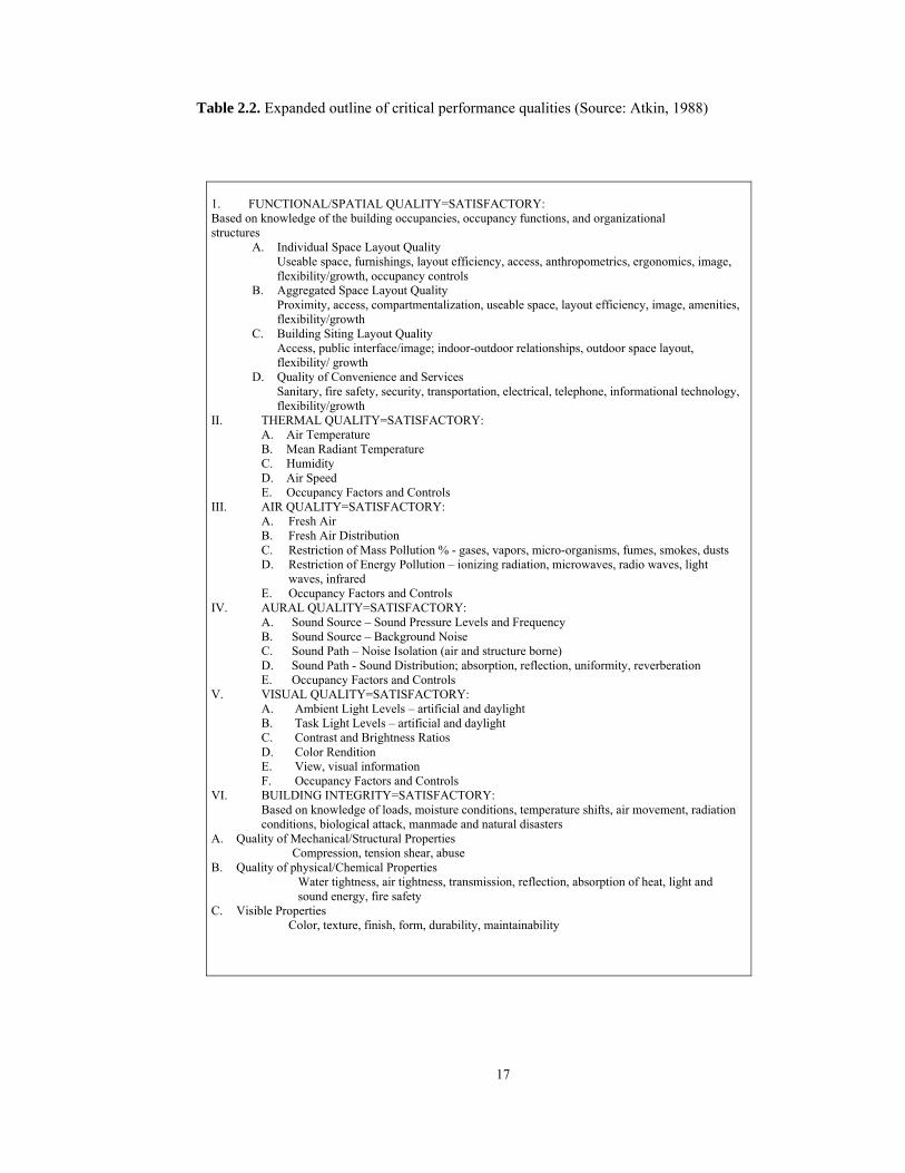
Atkin (1988) declares that for improving the productivity and user satisfaction,
it is necessary to define a manageable list of critical performance qualities for office
environments, for their evaluation, programming, design, construction, maintenance
and use. In many instances, building diagnostics (for determining collective
professional competence inherent in existing building practices) is the first priority
before predicting the requirements for future building intelligence performance. A
minimum of six performance criteria might capture the performance qualities that are
required in the workplace today; spatial (or functional) quality, thermal quality, air
quality, aural quality, visual quality, as well as building integrity against degradation
as it is shown in Table 2.2. The programming, design, construction and operation of
the buildings for total building performance should guarantee immediate
appropriateness of the integrated setting for the building occupancies and functions;
the long term reliability of the integrated setting to perform as intended through the
life of the facility (given appropriate maintenance and use); and flexibility to
accommodate changing functions and occupancies, maintaining suitability
throughout the building’s life cycle.
17
Table 2.2. Expanded outline of critical performance qualities (Source: Atkin, 1988)
1. FUNCTIONAL/SPATIAL QUALITY=SATISFACTORY: Based on knowledge of the building occupancies, occupancy functions, and organizational structures
A. Individual Space Layout Quality Useable space, furnishings, layout efficiency, access, anthropometrics, ergonomics, image, flexibility/growth, occupancy controls
B. Aggregated Space Layout Quality Proximity, access, compartmentalization, useable space, layout efficiency, image, amenities, flexibility/growth
C. Building Siting Layout Quality Access, public interface/image; indoor-outdoor relationships, outdoor space layout, flexibility/ growth
D. Quality of Convenience and Services Sanitary, fire safety, security, transportation, electrical, telephone, informational technology, flexibility/growth
II. THERMAL QUALITY=SATISFACTORY: A. Air Temperature B. Mean Radiant Temperature C. Humidity D. Air Speed E. Occupancy Factors and Controls
III. AIR QUALITY=SATISFACTORY: A. Fresh Air B. Fresh Air Distribution C. Restriction of Mass Pollution % - gases, vapors, micro-organisms, fumes, smokes, dusts D. Restriction of Energy Pollution – ionizing radiation, microwaves, radio waves, light
waves, infrared E. Occupancy Factors and Controls
IV. AURAL QUALITY=SATISFACTORY: A. Sound Source – Sound Pressure Levels and Frequency B. Sound Source – Background Noise C. Sound Path – Noise Isolation (air and structure borne) D. Sound Path - Sound Distribution; absorption, reflection, uniformity, reverberation E. Occupancy Factors and Controls
V. VISUAL QUALITY=SATISFACTORY: A. Ambient Light Levels – artificial and daylight B. Task Light Levels – artificial and daylight C. Contrast and Brightness Ratios D. Color Rendition E. View, visual information F. Occupancy Factors and Controls
VI. BUILDING INTEGRITY=SATISFACTORY: Based on knowledge of loads, moisture conditions, temperature shifts, air movement, radiation conditions, biological attack, manmade and natural disasters
A. Quality of Mechanical/Structural Properties Compression, tension shear, abuse
B. Quality of physical/Chemical Properties Water tightness, air tightness, transmission, reflection, absorption of heat, light and sound energy, fire safety
C. Visible Properties Color, texture, finish, form, durability, maintainability

18
2.3.1. Information Systems
Coggan8 regards telecommunications and workplace automation as part of the
information systems in intelligent buildings. Intelligence with respect to
telecommunications in such buildings consist of many sophisticated telecom features
such as; private telephone exchange systems, cablevision, audio-visual and video-
conferencing, satellite communications, electronic mail, intranets and internet access.
The cost of telecommunications and work place automation can be done at a reduced
cost to tenants by virtue of the equipment being shared. Some of the factors involved
in workplace automation in intelligent buildings include, centralized data processing,
word processing, computer-aided design and information services.
2.3.2. Facilities management
Facilities management implies a computerized system that oversees and
controls building operations, generally energy and life safety. Although the potential
exists to integrate all facilities management activities into one large system, practical
and economic considerations discourage this. Since 1987, the American Society of
Heating, Refrigerating and Air-conditioning Engineers (ASHRAE) have worked on
the development of an open data communications protocol called BACnet. This
protocol enables control systems from multiple, competing manufacturers to
communicate or "inter-operate" with one another. In 1995, BACnet was formally
adopted as ASHRAE/ANSI Standard 135-1995.8
2.3.2.1. Life Safety Systems
“The traditional role of the security system was to keep out unwanted people.
The emphasis has now changed to one of preventing a wide range of harmful actions
taking place, such as bomb attacks or computer hacking, while at the same time
providing less and obtrusive monitoring and control.” (Harrison et al., 1998)
Coggan8 states that intelligence with respect to life safety in an intelligent building
8 Coggan, D. Smart buildings. Retrieved July 28, 2003, http://www.coggan.com/smartbuildings.html

19
consists of the use of high technology to maximize the performance of fire alarm and
security systems while at the same time minimizing costs. Life safety factors
involved in intelligent buildings include:
• Reduced manpower dependence,
• Closed-circuit television,
• Card access control,
• Smoke detection,
• Intrusion alarms,
• Emergency control of elevators, HVAC systems, doors and
• Uninterruptible power supplies.
2.3.2.2. Energy Management Systems
Energy efficiency still continues to be the peak point in intelligent building
design 35 years after the oil crisis in the early 1970s. Computerized systems are used
such as; Building Automation System (BAS), Energy Management System (EMS),
Energy Management and Control System (EMCS), Central Control and Monitoring
System (CCMS) and Facilities Management System (FMS) to reduce energy use to
the minimum without relinquishment from occupant comfort.9
Commercial buildings account for between 30 and 40 percent of national
energy use. Energy management systems, deal with the automation of specific aspect
of a building's services, such as lighting, heating and cooling. By controlling these
areas with automated systems, the building becomes not only more functional, it is
also much more energy efficient. For example, by turning off unnecessary lights and
not heating unoccupied rooms, commercial buildings can reduce utility bills by 20 to
30 percent. Overall energy can be reduced by up to 50 percent. (The New York
Times-August 1995)
According to the Worldwatch Institute, 40 percent of the energy consumed in
the United States each year comes from building construction, building material
9 Coggan, D. Smart buildings. Retrieved July 28, 2003, http://www.coggan.com/smartbuildings.html

20
manufacturing and building operations. Buildings also account for about 65 percent
of total U.S. electricity consumption. This energy consumption creates air and water
pollution while contributing to global warming (Odell, 2002).
As stated by Harrison (1998) a range of factors drives the need for energy conservation
measures in high-rise buildings:
• High-rise buildings are all air-conditioned and therefore expensive to run
• There is an arising concern about the preservation of the environment and yet
also growing pollution due to rapid urban development
• High-rise buildings are energy demanding because of their high population
density and because of the technologies they contain (such as computers and air-
conditioning)
According to Coggan10 strategies used by facilities management systems to
reduce energy consumption in intelligent buildings include:
• Programmed start/stop
• Optimal start/stop
• Duty cycling
• Set point reset
• Electric demand limiting
• Adaptive control
• Chiller/Boiler optimization
• Optimal energy sourcing
2.4. Façade Design in Intelligent Buildings
Atkin (1988) refers to Keenlyside’s statement about the need for
individual control of environmental quality for increased productivity of the
occupants. Further he assents that occupants are much healthier in naturally
ventilated buildings (occupant control), than in sealed, mechanically conditioned
buildings.
10 Coggan, D. Intelligent Buildings Simply Explained. Retrieved July 28, 2003, http://www.coggan.com/aboutintelligentbuildings.html
21
Harrison (1998) attributes a different purpose to the buildings apart from
symbolic or cultural functions, which is to create an artificial environment contained
by the building skin. Adding that skin should not be considered as a barrier, but as a
“moderator of flows” which is three-dimensional, having thickness and therefore
has the ability to store energy. Water, air, sound, light, view, heat, fire, pollution,
security, safety and explosions have to be controlled by the skin and all of these
factors should be combined in a balanced way. However, conventional façades are
not capable of responding to changing environmental requirements and occupant
needs whereas dynamic (intelligent) façades are able to keep upright all these factors
above.
In intelligent façades there are sensors located in different points in intelligent
buildings where necessary. By means of sending data to control centers and taking
feedback they activate the mechanical systems in the façade to adapt to the changing
milieu. For instance, louvers rotate and adjust to the proper position, blinds turn out
to be open/close or ventilation flaps behave likewise considering different parameters
such as solar angle, intensity and direction etc.
Atkin (1988) declares that adapting control centers for intelligent façades is
insufficient because there are no ‘typical’ users, activities, or exterior environments
and adds that regulations and existing codes are inadequate presenting only 80% user
satisfaction as well as these codes assume that building occupants respond
independently to their thermal, air quality, acoustic, visual and special environments.
Furthermore, he adds that occupants are complex sensors of environmental
conditions, severely affected by sick building syndrome that occurs due to poorly
maintained conventional HVAC systems. Besides, user-oriented controls can allow
changes that reflect the occupants’ environmental needs in an integrated manner.
Table 2.3 shows the relations between the illnesses and ventilation types of the
buildings.

22
Table 2.3 Study of air-quality-related illnesses (Source: Atkin, 1988)
SICK BUILDING SYNDROME NATURAL
VENTILATION MECHANICAL VENTILATION
NO HUMIDIFICATION
HUMIDIFICATION NO CIRCULATION
HUMIDIFICATION RECIRCULATORY
SYMPTOMS NASAL 6 14 22 17 EYE 6 8 28 18 MUCOUS MEMBRANES 8 13 38 33 CHEST TIGHTNESS 2 1 10 8 SHORTNESS OF BREATH 2 __ 4 3 HEADACHES 16 37 35 40 DRYSKIN 6 6 16 15 LETHARGY 14 45 50 52
What is important in façade design in addition to the technical requirements is
the occupiers’ comfort level. Here with comfort level it is intended that
psychological as well as physiological conditions have to be satisfied for all kind of
dwellers. This brings the responsiveness to all kind of changes that happen inside and
outside immediately. Harrison (1998) enumerates a variety of factors for the building
skin to control:
Water: rain, humidity, condensation
Air: wind, ventilation
Sound: desired, undesired
Light: sunlight, glare, artificial
View: in and out, private or public
Heat: solar radiation, air temperature
Fire: flames, heat, smoke
Pollution: gases, particles
Security: breaking in
Safety: falling out
Explosions: from outside and inside
There are some parameters affecting the design of the façades therefore the
milieu. Harrison (1998) says that it is very complex to moderate and control
environments, that are constantly under change, including seasonal and daily
variations as well as variation between façades facing different directions. He
exemplifies various comfort conditions simultaneously creating conflicts such as

23
daylight is desired though glare is not; solar gain is useful in winter but undesirable
in summer; ventilation is needed, while keeping noise and pollution out implies a
closed window; a good view is required while still maintaining security.
2.4.1. Façade Typologies
Façade typologies according to Compagno (1999) can be determined by
regarding the number of glazing skins and location of the shading devices. Various
combinations of these two factors constitute different typologies in a very wide range
that play a significant role in keeping heat losses low and avoiding undesired heat
gains. Furthermore, Harrison (1998) remarks several attributes that have to be
maximized for office façades such as natural ventilation, natural lighting, and good
views through clear glass and energy efficiency. Various common façade systems are
given below according to Compagno (1999).
i. Single-skin façades; to achieve a certain level of solar control in a single-
skin façade, coatings can be applied to the glass to absorb and reflect wavelengths in
the visible range together with interior, exterior or integrated solar control devices.
As their properties are fixed, they also restrict solar gain in the colder months and
reduce day lighting levels. For this reason it is necessary to provide additional
adjustable solar control measures in buildings with large surface areas of façade
glazing and in buildings where air conditioning requirements are strictly regulated.
ii. Multiple-Skin Façades; in the case of multiple-skin façades solar control
devices are generally placed between the glazing skins. These façades can be further
divided into the following two types:
a. Mechanically Ventilated Cavity Façades; there is a single glass sheet
with an interior solar control device behind a façade constituting an air cavity.
Working principle here is the stack effect that air is exhausted from the rooms to the
cavity by the lower pressure occurred in this space. Here the air warms up, removes
the heat from the solar control devices, and is then extracted by means of mechanical
ventilation. Vertical louver blinds or textile blinds can be used in the cavity.
Horizontal blinds are not suitable to provide optimum airflow. Thermal comfort
conditions in the office space nearer to the window increases and energy costs for
heating and cooling reduces due to the temperature difference between the air in the

24
room and the surface of the glass is minimized in this typology.
b. Double-skin Façades; in this type solar control devices are placed in the
cavity between two skins, which protects them from the influences of weather and air
pollution, a factor of particular importance in high-rise buildings or ones situated in
the vicinity of busy roads. Re-radiation from absorbed solar radiation is emitted into
the intermediate cavity, a natural stack effect occurs, which causes the air to rise,
taking with it additional heat provides a further advantage to the double-skin façade.
2.4.2 Double-skin façades
One of the elements in IB’s is the double-skin façade, which is used to
manipulate heating and ventilation requirements in the interior spaces. DSFs in
intelligent buildings include windows and shading systems with optical and thermal
properties that can be dynamically changed in response to climate, occupant
preferences and building energy management control system (EMCS) requirements.
These include motorized shades, switchable electrochromic or gasochromic window
coatings. With Venetian blinds used typically in the cavity, the modes of operation
include tilt angle and retraction (up, down), which satisfies the criteria needed for
both solar heat gain control and day lighting. Whereas, with roller shades, degree of
shade retraction can be controlled, this can block view and daylight when providing
solar heat gain control. As a result of actively managing lighting and cooling, electric
loads can be reduced by 20-30% and day lighting benefits increased in commercial
buildings while providing maximum flexibility in energy use.11
A typical DSF has three layers of glazing with ventilation and solar control
devices between the outer two glazing layers, although some ventilate the space
between the inner glazings. In most cases, the airflow through the glazing cavity is
driven by natural buoyancy (hot air rises) aided by wind pressure differences,
although some systems use small fans (often driven by photovoltaics). In hybrid
systems, HVAC supply or exhaust air flows are directed through a glazing cavity
11 Lee et al., High-Performance Commercial Building Façades, Active Load Management with Advanced Window Wall Systems: Research and Industry Perspectives, June 2002, Retrieved Aug. 02, 2003, http://gaia.lbl.gov/hpbf/main.html
25
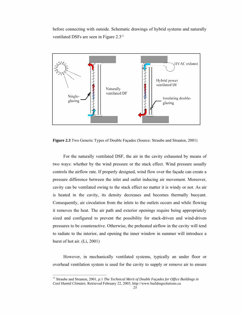
before connecting with outside. Schematic drawings of hybrid systems and naturally
ventilated DSFs are seen in Figure 2.312
Figure 2.3 Two Generic Types of Double Façades (Source: Straube and Straaten, 2001)
For the naturally ventilated DSF, the air in the cavity exhausted by means of
two ways: whether by the wind pressure or the stack effect. Wind pressure usually
controls the airflow rate. If properly designed, wind flow over the façade can create a
pressure difference between the inlet and outlet inducing air movement. Moreover,
cavity can be ventilated owing to the stack effect no matter it is windy or not. As air
is heated in the cavity, its density decreases and becomes thermally buoyant.
Consequently, air circulation from the inlets to the outlets occurs and while flowing
it removes the heat. The air path and exterior openings require being appropriately
sized and configured to prevent the possibility for stack-driven and wind-driven
pressures to be counteractive. Otherwise, the preheated airflow in the cavity will tend
to radiate to the interior, and opening the inner window in summer will introduce a
burst of hot air. (Li, 2001)
However, in mechanically ventilated systems, typically an under floor or
overhead ventilation system is used for the cavity to supply or remove air to ensure
12 Straube and Straaten, 2001, p.1 The Technical Merit of Double Façades for Office Buildings in Cool Humid Climates. Retrieved February 22, 2003, http://www.buildingsolutions.ca

26
distribution of fresh air. Here, air is forced into the cavity by mechanical devices. Air
rises and removes heat from the cavity and continues upwards to be expelled or re-
circulated. Since air is not pumped inwards directly from the outdoors there is
potentially less risk of condensation and pollution in the cavity. (Barreneche, 1995)
Two kinds of operations take place in the DSF systems, which are winter and
summer operations. In summer, air in the cavity removes the heat by means of stack
effect otherwise heat accumulates in the cavity and passes through interior spaces.
Therefore, the temperature of the inner skin is kept lower and the conduction,
convection and radiation from the inner pane to the occupied space reduces.
Accordingly less heat is transferred from the outside to the inside, and less energy is
required to cool the space. Whereas in winter there are two typical scenarios; first
one has a closed system, with no air circulation through the cavity. While the cavity
heats up, it increases the temperature of the inner pane, and thereby reduces the
conductive, convective and radiant losses. In the second situation, warm air is
introduced into the cavity from the interior to warm the inner pane of glass and
achieve the same results. The air is then ducted to the building systems plant where it
may be run through a heat exchanger to pre-heat the incoming air. (Arons, 2000)
i. Objectives
Arons (2000) examines major objectives of double skin façades in seven
headings below:
Energy savings and ecological responsibility: energy savings are achieved by
minimizing solar loading at the perimeter of buildings and reducing cooling
loads of the buildings.
Natural ventilation: occupants can leave windows open during various
climatic conditions such as wind, rain, etc. Exterior skin protects the entire
building, and by doing so, allows natural ventilation through air corridors
between the skins. It is possible to maintain windows open 24 hours and not
compromise interior comfort with a double-skin façade.
Cost savings: Double-skin façades are significantly more expensive to install
than conventional curtain wall systems considering only the cost of the

27
installed façade. With additional installation costs typical façade systems
have ranged significantly from 20% to perhaps 300%. However, it has been
claimed by Saelens (1997) that the use of DSFs can reduce the initial
construction cost of buildings by reducing heating and cooling loads of the
envelope in long-term.
Sound reduction: It is possible to achieve the same acoustic insulation with
the windows open as with that obtained in classical glass façades with the
windows closed.
User control and comfort: By enabling occupants to control light with louvers
or shades and to control air movement and temperature with operable
windows, not only comfort is enhanced, but the sense of well being that
comes with controlling one’s environment is also nurtured. The degree of
user control, which may or may not coincide with improving actual comfort
conditions or energy efficiency, must be reconciled with building
management systems that may more rigidly control these factors.
Occupant productivity and contact with the environment: If a more
comfortable, controllable and visually pleasing environment can be created,
then workers become more productive.
Security: DSFs offer a relatively unimposing manner for achieving security.
Rather than project openings with bars or metal grating DSFs have a
continuous sheet of glass with relatively small vents to allow for the entrance
and exit of air. The result is a transparent barrier that breathes. (Arons, 2000)
ii. Energy Performance of Double-skin façades
Li (2001) classifies the elements for the configuration of the DSF systems that
affect the overall performance as follows:
Natural vs. mechanically assisted ventilation
Single story vs. multiple story module
Glass layer properties and sequence
Cavity size and depth
Shading device location and properties
Number and place of the inlets and outlets
28
The direction of the façade
Hensen13 states that the prediction of the performance of a double-skin façade
is not a trivial exercise. The temperature and airflow result from many simultaneous
thermal, optical and fluid flow processes, which interact and are highly dynamic.
These processes depend on geometric, thermo-physical, optical and aerodynamic
properties of the various components of the double-skin façade structure and of the
building itself. The temperature inside the offices, the ambient temperature, wind
speed, wind direction, transmitted and absorbed solar radiation and angles of
incidence govern the main driving forces.
Daniels (1997) states that when outside air temperature is 25°C, the highest
cavity temperature can vary from 45°C to 70°C in a typical naturally ventilated
double façade system with different properties of shading devices. Daniels also
points out that during direct solar radiation and calm days, natural ventilation caused
by thermal buoyancy is clearly measurable, since the temperature increases per story
by approximate 1.5-3°C (for direct solar radiation) or by 1°C per floor on overcast
days. Natural ventilation due to thermal buoyancy on calm days proves ineffective
only when external temperatures are significantly higher than internal temperatures.
Also, Barakat (1987) declares that the airflow through the window cavity
recovered a large fraction of the heat loss. This represented about 50% of the energy
required to heat ventilation air. If compared to a conventional window, the effective
steady state U-value of the airflow window was found to be 0.5 W/m²K. The overall
reduction in purchased energy of the supply-air window unit relative to a similar
double-glazed window unit or to a triple glazed window unit is about 25% and 20%,
correspondingly.
Li (2001) refers to Gan’s statement about the effects of different wall
configurations. It is reported that the cavity ventilation rate induced by the thermal
buoyancy increases with the wall temperature, solar heat gain, wall height and 13 Hensen et al., Modeling and Simulation of a Double-Skin Façade System. Retrieved Aug. 04, 2003, http://www.bwk.tue.nl/fago/hensen/publications/02_ashrae

29
thickness providing that the dimension of the inlet and outlet openings increases with
channel width, the ventilation rate also increases with the distance between the
outside and inside glazing layers.
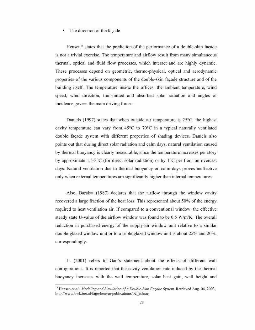
Saelens and Hens (2002) focus on the energy saving objectives of three
multiple skin façade (MSF) typologies used in a single office facing south. To
simulate the energy demand of the office, a cell centered control volume model,
describing the MSF, is coupled to a dynamic energy simulation program. In the
study four one story solutions have been identified; a conventional façade with an
insulated glazing unit (IGU), a naturally ventilated double skin façade (DSF), a
mechanically ventilated airflow window (AFW) and a mechanically ventilated
supply air window (SUP) as seen in Figure 2.4. The traditional solution consists of
an insulating glazing unit with a U-factor of 1.23 W/m²K and a solar transmittance
(g-value) of 0.59. The window is equipped with an exterior roller blind, by adding a
clear glass pane is in front of the sun shading and allowing exterior air to enter the
cavity to create a DSF. A supply window is designed by mechanically ventilating the
cavity and providing ventilation air to the office. An insulating glazing unit is placed
at the outside, the single glass at the inside and the cavity is mechanically ventilated
with interior air to create an airflow window. All systems are equipped with a roller
blind, which is lowered as soon as the incident solar radiation exceeds 100 W/m².
The abbreviations referring to the mechanically ventilated variants are labeled
with the airflow rate through the MSF cavity (Ga), which is expressed, as the air
change of the office and Gv is the hygienic ventilation airflow rate. The abbreviations
for the naturally ventilated façades express the number of grids opened at the inlet
and outlet of the cavity. For example DSF 01 indicates the double skin façade with
one outlet and inlet grid open.
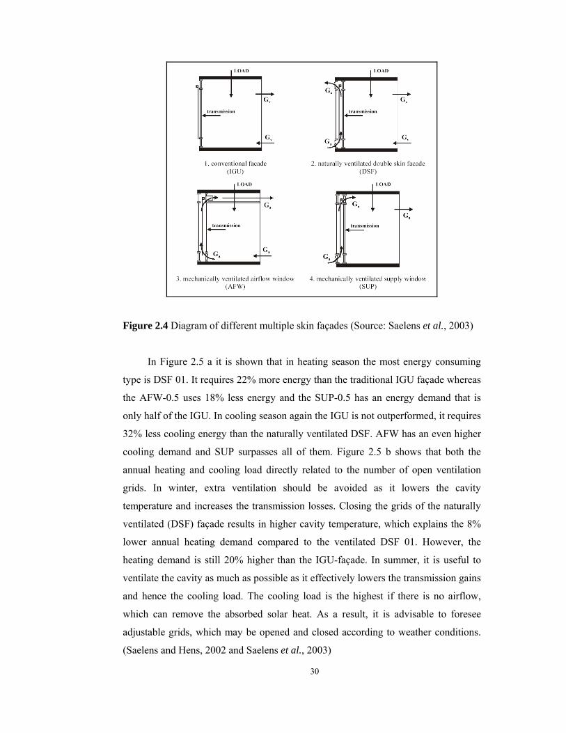
30
Figure 2.4 Diagram of different multiple skin façades (Source: Saelens et al., 2003)
In Figure 2.5 a it is shown that in heating season the most energy consuming
type is DSF 01. It requires 22% more energy than the traditional IGU façade whereas
the AFW-0.5 uses 18% less energy and the SUP-0.5 has an energy demand that is
only half of the IGU. In cooling season again the IGU is not outperformed, it requires
32% less cooling energy than the naturally ventilated DSF. AFW has an even higher
cooling demand and SUP surpasses all of them. Figure 2.5 b shows that both the
annual heating and cooling load directly related to the number of open ventilation
grids. In winter, extra ventilation should be avoided as it lowers the cavity
temperature and increases the transmission losses. Closing the grids of the naturally
ventilated (DSF) façade results in higher cavity temperature, which explains the 8%
lower annual heating demand compared to the ventilated DSF 01. However, the
heating demand is still 20% higher than the IGU-façade. In summer, it is useful to
ventilate the cavity as much as possible as it effectively lowers the transmission gains
and hence the cooling load. The cooling load is the highest if there is no airflow,
which can remove the absorbed solar heat. As a result, it is advisable to foresee
adjustable grids, which may be opened and closed according to weather conditions.
(Saelens and Hens, 2002 and Saelens et al., 2003)

31
Figure 2.5 Annual heating and cooling load per unit of floor area for the basic variants
and the parameter analysis (Source: Saelens and Hens, 2002)
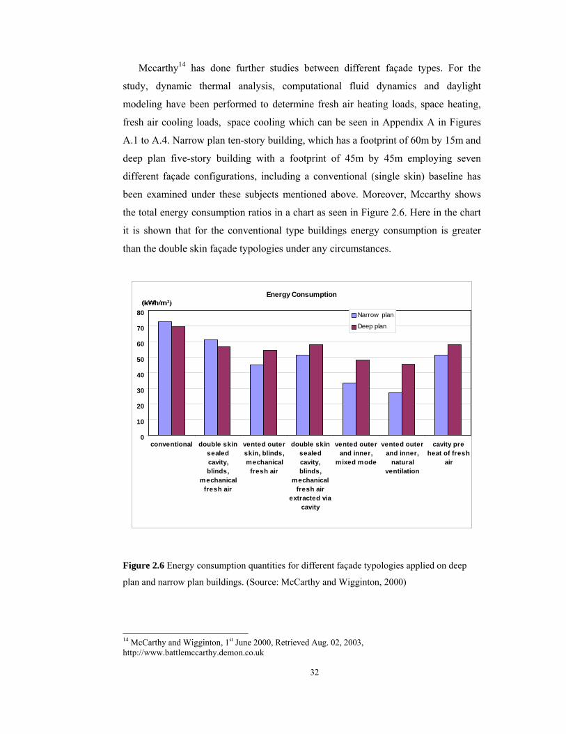
32
Mccarthy14 has done further studies between different façade types. For the
study, dynamic thermal analysis, computational fluid dynamics and daylight
modeling have been performed to determine fresh air heating loads, space heating,
fresh air cooling loads, space cooling which can be seen in Appendix A in Figures
A.1 to A.4. Narrow plan ten-story building, which has a footprint of 60m by 15m and
deep plan five-story building with a footprint of 45m by 45m employing seven
different façade configurations, including a conventional (single skin) baseline has
been examined under these subjects mentioned above. Moreover, Mccarthy shows
the total energy consumption ratios in a chart as seen in Figure 2.6. Here in the chart
it is shown that for the conventional type buildings energy consumption is greater
than the double skin façade typologies under any circumstances.
Energy Consumption
0
10
20
30
40
50
60
70
80
conventional double skinsealedcavity,blinds,
mechanicalfresh air
vented outerskin, blinds,mechanical
fresh air
double skinsealedcavity,blinds,
mechanicalfresh air
extracted viacavity
vented outerand inner,
mixed mode
vented outerand inner,
naturalventilation
cavity preheat of fresh
air
Narrow plan
Deep plan
Figure 2.6 Energy consumption quantities for different façade typologies applied on deep
plan and narrow plan buildings. (Source: McCarthy and Wigginton, 2000)
14 McCarthy and Wigginton, 1st June 2000, Retrieved Aug. 02, 2003, http://www.battlemccarthy.demon.co.uk
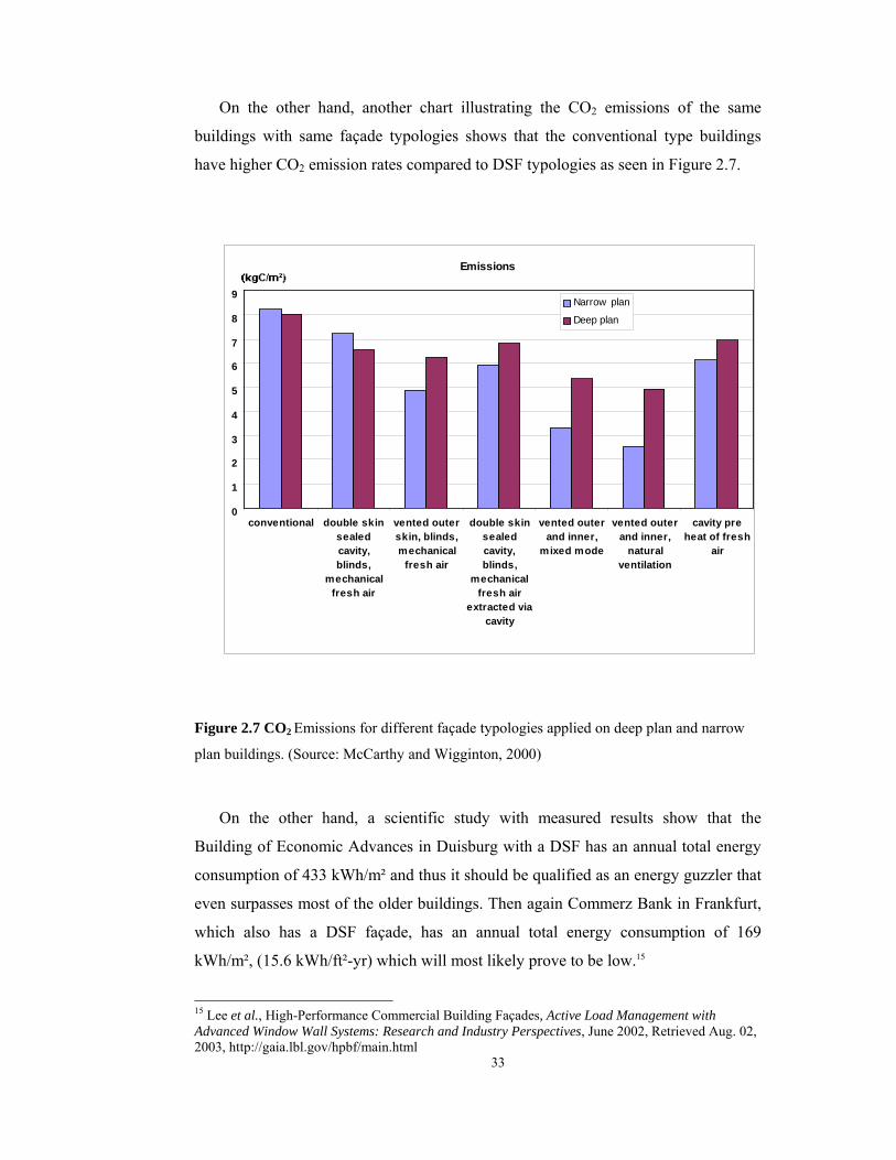
33
On the other hand, another chart illustrating the CO2 emissions of the same
buildings with same façade typologies shows that the conventional type buildings
have higher CO2 emission rates compared to DSF typologies as seen in Figure 2.7.
Emissions
0
1
2
3
4
5
6
7
8
9
conventional double skinsealedcavity,blinds,
mechanicalfresh air
vented outerskin, blinds,mechanical
fresh air
double skinsealedcavity,blinds,
mechanicalfresh air
extracted viacavity
vented outerand inner,
mixed mode
vented outerand inner,
naturalventilation
cavity preheat of fresh
air
Narrow plan
Deep plan
Figure 2.7 CO2 Emissions for different façade typologies applied on deep plan and narrow
plan buildings. (Source: McCarthy and Wigginton, 2000)
On the other hand, a scientific study with measured results show that the
Building of Economic Advances in Duisburg with a DSF has an annual total energy
consumption of 433 kWh/m² and thus it should be qualified as an energy guzzler that
even surpasses most of the older buildings. Then again Commerz Bank in Frankfurt,
which also has a DSF façade, has an annual total energy consumption of 169
kWh/m², (15.6 kWh/ft²-yr) which will most likely prove to be low.15
15 Lee et al., High-Performance Commercial Building Façades, Active Load Management with Advanced Window Wall Systems: Research and Industry Perspectives, June 2002, Retrieved Aug. 02, 2003, http://gaia.lbl.gov/hpbf/main.html

34
Moreover, Lee15 refers to Gertis’s statement that architectural magazines have
published a significant amount of non-critical literature in which the claimed
performance has proven later to be wrong or untrue. After 1996, more critical
reviews have been published indicating increased dissatisfaction with DSFs and
countering the euphoric descriptions from the early 1990s. Gertis also notes several
problems with literature that cite simulation results. First, the results are usually
given for hypothetical boundary conditions with a simulation model developed early
in the design process. Often the boundary conditions are not exactly stated so the
results are fairly useless since no critical interpretation can be made and other
sources provide measurements made under laboratory conditions thus very few
publications have real world measurements.
In his article Gertis declares that the air temperature in the gap can create
significant thermal discomfort and force closure of interior windows designed to
allow natural ventilation and gives an example where the temperature of a southwest-
facing DSF is given as a function of air changes in the gap and the total solar
transmittance of the exterior skin with shading devices. For an exterior air
temperature of 30°C, the air temperature of the gap can approach 40-50°C.
Substantial cooling is not achieved until the air change rate within the cavity is 20,
which is hard to achieve with natural ventilation and reasonable air gaps, unless the
façade is opened to more than 30%, which then eliminates the acoustical
performance of the façade. In order to achieve low air temperatures in the gap, one
could also reduce the total solar energy transmittance to a maximum of 0.30, but the
interior room will get very dark and increase electric lighting energy use.15
There are different opinions ranging in a very large extent about the performance
of double skin façades. The speculation of these ideas on this subject may emerge
from the lack of scientific information. There have been many studies about the
performance of these types and still there are studies ongoing on this subject. The
variety of numerous parameters affecting the performance reduces the reliability of
the results. The simulation tools used today are incapable of showing the real results
they can only give approximate values. However, approximations can only help for

35
having an idea about the performance but cannot be accepted as facts.
iii. Performance parameters
Integration of façade systems implies a design that balances numerous (and often
conflicting) performance parameters.16 There is a wide range of parameters that
should be taken into account in order to design a system that responds to energy
concerns. Moreover, there is a significant point to remember that the number and
interdependency of the parameters can create a problem that is difficult to overcome
if the relative role of each parameter is not understood well. It is therefore important
to determine the most important variables. As there are too many parameters for the
design of a DSF Arons (2000) summarizes the full complexity of the system and
distilled it under ten headings;
1. Spatial aspects
The depth of the cavity
The height of the window
2. Glazing properties
The emissivity, transmissivity, reflectivity and absorptivity of each pane
3. Thermal and structural qualities of frames
4. The location of mullions
5. Blind properties
Location dimensions and spacing
Emissivity, absorptivity and reflectivity of the material
6. Air movement path
Inlet to the inside or outside
Forced or natural convection
7. Controls
Individual control of the blinds and operable windows
Building control of blinds and operable of windows
8. Interaction with other systems such as mass storage and air supply and exhaust
16 Lee et al.., High-Performance Commercial Building Façades, Active Load Management with Advanced Window Wall Systems: Research and Industry Perspectives, June 2002, Retrieved Aug. 02, 2003, http://gaia.lbl.gov/hpbf/main.html

36
9. The configuration and interrelationship of other mechanical components such as
ducts, fans and controls
10. The overall color and visual reflectivity of the system
iv.Typologies
Saelens and Hens (1997) define three primary identifiers for DSFs, which are
nature of airflow (inlet and exhaust same side, supply from exterior to interior, and
exhaust from interior to exterior), generation of airflow (natural or forced
convection) and horizontal partition of the façade (window or façade) However,
Arons (2000) declares that there are primary and secondary identifiers in defining
typologies of DSFs. According to Arons, airflow patterns and building height are
counted as primary identifiers whereas layering composition of glass, gases, and
shading devices; depth, horizontal extent (length along the façade) and vertical extent
of the cavity; operability of the full height doors (sliding or pivot) or tilt-turn
windows on the inner pane that are either opened by occupants or by automated
means, materials of the interior and exterior skin of the double façade are considered
as secondary identifiers.
According to Boake17 two classification systems exist which are British and
North American. Boake refers to Lang and Herzog’s statement that there are three
basic systems in North American typologies that vary significantly with respect to
ventilation method and their ability to reduce overall energy consumption that are;
buffer systems, extract air systems and twin face systems. North American
classification is more general than British one in which McCarthy created a
categorization of five primary types (plus sub-classifications) based on
commonalities of façade configuration and the manner of operation. These are:
Category A: Sealed inner skin subdivided into mechanically ventilated cavity with
controlled flue intake versus a ventilated and serviced thermal flue.
17 Boake et al., The Tectonics of the Double Skin: What are double façades and how do they work? Retrieved Aug. 01, 2003, http://www.fes.uwaterloo.ca/architecture/faculty_projects/terri/ds/tectonic.pdf
37
Category B: Openable inner and outer skins subdivided into single story cavity
height versus full building cavity height.
Category C: Openable inner skin with mechanically ventilated cavity with
controlled flue intake
Category D: Sealed cavity, either zoned floor by floor or with a full height cavity.
Category E: Acoustic barrier with either a massive exterior envelope or a
lightweight exterior envelope
a. Buffer System
These façades predate insulating glass and were invented to maintain daylight
into buildings while increasing insulating and sound properties of the wall system.
They use two layers of single glazing spaced 250 to 900 mm apart, sealed and
allowing fresh air into the building through additional controlled means either a
separate HVAC system or box type windows which cut through the overall double
skin. Shading devices can be included in the cavity.18
18 Boake et al., The Tectonics of the Double Skin: What are double façades and how do they work? Retrieved Aug. 01, 2003, http://www.fes.uwaterloo.ca/architecture/faculty_projects/terri/ds/tectonic.pdf

38
Figure 2.8 Buffer System (Source: Boake et al., The Tectonics of the Double Skin: What
are double façades and how do they work? Retrieved Aug. 01, 2003,
http://www.fes.uwaterloo.ca/architecture/faculty_projects/terri/ds/tectonic.pdf
A modern example of this type is the Business Promotion Center in Duisberg,
Germany by Foster and Partners. The envelope incorporates an outer glass layer,
single-glazed panels fastened to aluminum tension rods, an inner glass, operable
low-E double-glazed panels, and an 8-inch (200mm) cavity between layers. Within
the cavity, computer-controlled perforated Venetian blinds provide solar control and
radiation collection. Conditioned air rises through the continuous cavity, and is then
expelled through the top by the stack effect. In summer, this airflow traps and
removes the heat. In winter, the cavity serves as a thermal buffer to capture and offer
warm air for occupants through sliding windows (Li, 2001). Each room has
individual controls in addition to computer-controlled light and temperature cursors.
This building belongs to category C in British classification, which is openable inner
skin.

39
Figure 2.9 Business promotion center façade detail Figure 2.10 Double-skin façade
(Sources: Foster and Partners web site, Retrieved 01.Aug. 2003,
http://www.fosterandpartners.com)
Photocells detect daylight levels and operate solar control blind. The outer skin
is multi-layered and efficient that no heating is required, even in the coldest northern
winter. Cooling systems, rather than occupying a huge floor or ceiling void, have
been miniaturized and integrated within the fabric of the building. Instead of using
chilled air, dramatic drops in temperature can be achieved by moving chilled water
through pipes, distributed through a system similar to the fins on a car radiator. The
building generates and harvests its own energy. It burns natural gas and, by means of
a cogenerator, makes its own electricity. The by-product of that process - heat that
would normally be wasted - is put through an absorption cooling plant to produce
chilled water. This is not only an ecologically responsible solution: the developer
makes a significant annual profit from energy management. 19
b. Extracted System
These are comprised of a second single layer of glazing placed on the interior of
a main façade of double-glazing. The cavity between the two layers of glazing
becomes part of the HVAC system. The heated air between the glazing layers is
extracted through the cavity with the use of fans and thereby tempers the inner layer
of glazing while the outer layer of insulating glass minimizes heat-transmission loss.
19 Foster and Partners web site, Retrieved 01.Aug. 2003, http://www.fosterandpartners.com

40
Figure 2.11 Extracted System
(Source: Boake et al., The Tectonics of the Double Skin, Retrieved Aug. 01, 2003,
http://www.fes.uwaterloo.ca/architecture/faculty_projects/terri/ds/tectonic.pdf)
The air contained within the system is used by the HVAC system. Fresh air is
supplied by HVAC and precludes natural ventilation. These systems tend not to
reduce energy requirements, as fresh air changes must be supplied mechanically.
Occupants are prevented from adjusting the temperature of their individual spaces.
Shading devices are often mounted in the cavity. The space between the layers of
glass ranges from around 150 mm to 900 mm and is a function of the space needed to
access the cavity for cleaning as well as the dimension of the shading devices. This
system is used where natural ventilation is not possible (for example in locations
with high noise, wind or fumes).20
One of the examples to this type is Helicon Building designed by Sheppard
Robson in 1995 in London. The building consists of a single retail outlet on the
20 Boake et al., The Tectonics of the Double Skin: What are double façades and how do they work? Retrieved Aug. 01, 2003, http://www.fes.uwaterloo.ca/architecture/faculty_projects/terri/ds/tectonic.pdf
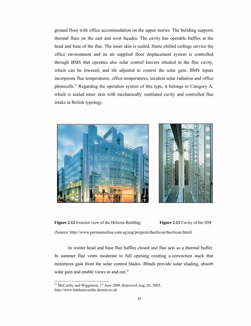
41
ground floor with office accommodation on the upper stories. The building supports
thermal flues on the east and west façades. The cavity has operable baffles at the
head and base of the flue. The inner skin is sealed. Static chilled ceilings service the
office environment and an air supplied floor displacement system is controlled
through BMS that operates also solar control louvers situated in the flue cavity,
which can be lowered, and tilt adjusted to control the solar gain. BMS inputs
incorporate flue temperatures, office temperatures, incident solar radiation and office
photocells.21 Regarding the operation system of this type, it belongs to Category A,
which is sealed inner skin with mechanically ventilated cavity and controlled flue
intake in British typology.
Figure 2.12 Exterior view of the Helicon Building Figure 2.13 Cavity of the DSF
(Source: http://www.permasteelisa.com.sg/eng/projects/theelicon/theelicon.html)
In winter head and base flue baffles closed and flue acts as a thermal buffer.
In summer flue vents moderate to full opening creating a convection stack that
minimizes gain from the solar control blades. Blinds provide solar shading, absorb
solar gain and enable views in and out.21
21 McCarthy and Wigginton, 1st June 2000, Retrieved Aug. 02, 2003, http://www.battlemccarthy.demon.co.uk

42
Figure 2.14 Story-height double-skin façade of Helicon Building (Source:
http://www.permasteelisa.com.sg/eng/projects/theelicon/theelicon.html)
c. Twin Face system
This system consists of a conventional curtain wall or thermal mass wall
system inside a single glazed building skin. This outer glazing may be safety or
laminated glass or insulating glass. Shading devices may be included. These systems
must have an interior space of at least 500 to 600 mm to permit cleaning. These
systems may be distinguished from both Buffer and Extract air systems by their
inclusion of openings in the skin to allow for natural ventilation. The single glazed
outer skin is used primarily for protection of the air cavity contents (shading devices)
from weather. With this system, the internal skin offers the insulating properties to
minimize heat loss. The outer glass skin is used to block or slow the wind in high-
rise buildings and allows interior openings and access to fresh air without the
associated noise or turbulence.22

43
Figure 2.15 Twin Face system (Source: Boake et al., The Tectonics of the Double Skin:
What are double façades and how do they work?, Retrieved Aug. 01, 2003,
http://www.fes.uwaterloo.ca/architecture/faculty_projects/terri/ds/tectonic.pdf)
Windows on the interior façade can be opened, while ventilation openings in
the outer skin moderate temperature extremes within the façade. The use of windows
can allow for nighttime cooling of the interior thereby lessening cooling loads of the
building’s HVAC system. For sound control, the openings in the outer skin can be
staggered or placed remotely from the windows on the interior façade. The RWE AG
Tower, Essen, Germany completed in 1998 by Ingenhoven and Overdiek Partners
would typify a classic twin-face building at the same time fits in the category B type
2 in British classification that is openable inner and outer skins with single story
cavity height.23
22 Boake et al., The Tectonics of the Double Skin: What are double façades and how do they work? Retrieved Aug. 01, 2003, http://www.fes.uwaterloo.ca/architecture/faculty_projects/terri/ds/tectonic.pdf 23 Boake et al., The Tectonics of the Double Skin: What are double façades and how do they work? Retrieved Aug. 01, 2003, http://www.fes.uwaterloo.ca/architecture/faculty_projects/terri/ds/tectonic.pdf

44
The inner and outer skin is separated with a distance of 500 mm. Louver blinds
that can be remotely controlled installed in the cavity. The blinds are protected by the
outer façade from wind and rain, and prevented by the inner façade from transmitting
the heat to the room, so as to maximize their shading and heat-reflecting effects.
Also, a set of roller shades made of fireproof cloth is fitted inside the inner façade. A
special sash called a "fish-mouth" designed to absorb and exhaust outside air was
built-in between stories. The outer façade consists of extra clear toughened glass,
each being fixed with bolts at eight points to the mullion. Such an outer façade
continues without a sash, to the top, so a transparent and light tower is formed. The
inner façade extends from floor to ceiling, which can be opened by 15cm allowing
natural ventilation.24
Figure 2.16 The diagonal flowing of air Figure 2.17 The composition of the façade
(Source: Space Modulator, Retrieved August 02, 2003, www.nsg.co.jp)
When the solar radiation is strong, the temperature inside the double skin rises as
in a greenhouse. However, owing to the air inlets and outlets fitted to the top and
bottom of each story, the air convects so as to take the heat away. The thermal
24 Space Modulator, Retrieved August 02, 2003, from Nippon Sheet Glass web site: www.nsg.co.jp
45
storage effect becomes vital, when there is a need to warm the room as in the winter
season. During 70% of the year, it is possible to live in the high-rise with the
controlled natural ventilation, without artificial cooling or heating. A system of
mechanical ventilation is also installed, but it is operated at most twice an hour,
whereas there is a need to ventilate 4-6 times hourly and to spend a large number of
energy to cool or heat the air in more conventional buildings. By harnessing the
natural ventilation, sick-building syndrome can be avoided. Owing to such sun
shading and thermal storage effects as well as natural ventilation, the energy
consumption for air-conditioning in the RWE Tower is calculated at some half of
that in conventional German buildings with single-skin façade and pair glass.25
v. Integration of DSFs into IB
In intelligent buildings DSFs with automated venting are used mostly to
reduce cooling loads during peak periods. Also lighting loads could be reduced with
day lighting controls with BMS. To create an integrated façade with the building
additional features such as automated exterior or interior shading systems, automated
switchable window (e.g., electrochromics) combined with day lighting controls with
1-2 hour notification and pre-cooling of thermal mass using nighttime natural or
mechanical ventilation through windows with 24-hour notification are added to
reduce cooling and lighting loads. In this case it is assumed that the facility manager
through a central control system deploys the shades automatically and lighting is
curtailed either manually or automatically. Switchable windows include
electrochromic or gasochromic glazings, which can be modulated from a clear to a
dark tinted state with either a small-applied voltage (3- 5V DC) or a minute influx of
gas such as hydrogen.26
vi Cost Analysis
Oesterle (2001) examines cost analyses under two headings that are investment
costs and operating (maintenance) costs. The investment costs contain façade
25 Nippon Sheet Glass, Retrieved 02.August.2003, www.nsg.co.jp 26 Lee et al., High-Performance Commercial Building Façades, Active Load Management with Advanced Window Wall Systems: Research and Industry Perspectives, June 2002, Retrieved Aug. 02, 2003, http://gaia.lbl.gov/hpbf/main.html
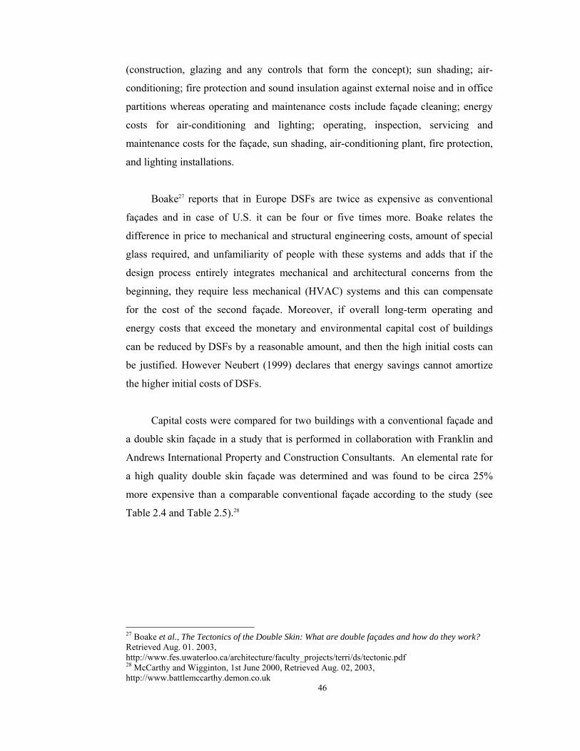
46
(construction, glazing and any controls that form the concept); sun shading; air-
conditioning; fire protection and sound insulation against external noise and in office
partitions whereas operating and maintenance costs include façade cleaning; energy
costs for air-conditioning and lighting; operating, inspection, servicing and
maintenance costs for the façade, sun shading, air-conditioning plant, fire protection,
and lighting installations.
Boake27 reports that in Europe DSFs are twice as expensive as conventional
façades and in case of U.S. it can be four or five times more. Boake relates the
difference in price to mechanical and structural engineering costs, amount of special
glass required, and unfamiliarity of people with these systems and adds that if the
design process entirely integrates mechanical and architectural concerns from the
beginning, they require less mechanical (HVAC) systems and this can compensate
for the cost of the second façade. Moreover, if overall long-term operating and
energy costs that exceed the monetary and environmental capital cost of buildings
can be reduced by DSFs by a reasonable amount, and then the high initial costs can
be justified. However Neubert (1999) declares that energy savings cannot amortize
the higher initial costs of DSFs.
Capital costs were compared for two buildings with a conventional façade and
a double skin façade in a study that is performed in collaboration with Franklin and
Andrews International Property and Construction Consultants. An elemental rate for
a high quality double skin façade was determined and was found to be circa 25%
more expensive than a comparable conventional façade according to the study (see
Table 2.4 and Table 2.5).28
27 Boake et al., The Tectonics of the Double Skin: What are double façades and how do they work? Retrieved Aug. 01. 2003, http://www.fes.uwaterloo.ca/architecture/faculty_projects/terri/ds/tectonic.pdf 28 McCarthy and Wigginton, 1st June 2000, Retrieved Aug. 02, 2003, http://www.battlemccarthy.demon.co.uk
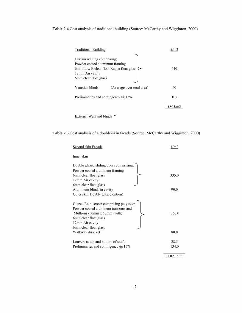
47
Table 2.4 Cost analysis of traditional building (Source: McCarthy and Wigginton, 2000)
Traditional Building £/m2 Curtain walling comprising; Powder coated aluminum framing 6mm Low E clear float Kappa float glass 640 12mm Air cavity 6mm clear float glass Venetian blinds (Average over total area) 60 Preliminaries and contingency @ 15% 105 £805/m2 External Wall and blinds *
Table 2.5 Cost analysis of a double-skin façade (Source: McCarthy and Wigginton, 2000)
Second skin Façade £/m2 Inner skin Double glazed sliding doors comprising; Powder coated aluminum framing 6mm clear float glass 335.0 12mm Air cavity 6mm clear float glass Aluminum blinds in cavity 90.0 Outer skin(Double glazed option) Glazed Rain-screen comprising polyester Powder coated aluminum transoms and Mullions (50mm x 50mm) with; 360.0 6mm clear float glass 12mm Air cavity 6mm clear float glass Walkway /bracket 80.0 Louvers at top and bottom of shaft 28.5 Preliminaries and contingency @ 15% 134.0 £1,027.5/m²
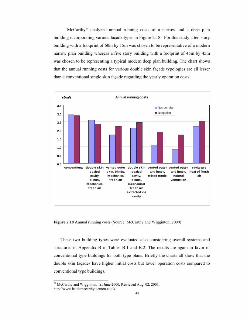
48
McCarthy29 analyzed annual running costs of a narrow and a deep plan
building incorporating various façade types in Figure 2.18. For this study a ten story
building with a footprint of 60m by 15m was chosen to be representative of a modern
narrow plan building whereas a five story building with a footprint of 45m by 45m
was chosen to be representing a typical modern deep plan building. The chart shows
that the annual running costs for various double skin façade typologies are all lesser
than a conventional single skin façade regarding the yearly operation costs.
Annual running costs
0.0
0.5
1.0
1.5
2.0
2.5
3.0
3.5
conventional double skinsealedcavity,blinds,
mechanicalfresh air
vented outerskin, blinds,mechanical
fresh air
double skinsealedcavity,blinds,
mechanicalfresh air
extracted viacavity
vented outerand inner,
mixed mode
vented outerand inner,
naturalventilation
cavity preheat of fresh
air
Narrow plan
Deep plan
Figure 2.18 Annual running costs (Source: McCarthy and Wigginton, 2000)
These two building types were evaluated also considering overall systems and
structures in Appendix B in Tables B.1 and B.2. The results are again in favor of
conventional type buildings for both type plans. Briefly the charts all show that the
double skin façades have higher initial costs but lower operation costs compared to
conventional type buildings.
29 McCarthy and Wigginton, 1st June 2000, Retrieved Aug. 02, 2003, http://www.battlemccarthy.demon.co.uk

49
vii. Critical review of DSFs
According to Boake30 supporters find these systems environmentally responsible
and containing overall energy savings. Furthermore, the environmental engineers
who have been involved in the design and construction stage of the buildings that use
DSF systems claim to have test data to substantiate their statements. Some numerical
data have been published that would indicate that significant energy savings are
possible. In these articles, energy savings include both mechanical plant and energy
to be expended (ongoing operating costs). However, the opponents site a wide range
of quantities that must be accounted for in determining a final savings value,
including, embodied energy, maintenance, life-cycle and durability of the system,
mechanical savings (operating cost as well physical plant), and additional floor area.
Moreover, Dr. Karl Gertis, who is one of the opponents and the director of
the Fraunhofer Institute of Building Physics in Stuttgart, asserts that simulations
cannot be relied on and practical measurement results are lacking. According to
Gertis, DSFs are not suitable for German local climate from the building physic’s
point of view. With respect to airflow in the gap and air exchange within the room,
Gertis critiques several literature references which assume that airflow in the gap will
be upwards based on thermal driven flow and downwards based on wind load on the
building (the higher wind load will give a higher static pressure). According to Gertis
actual airflow patterns in the gap will differ due to the instationary airflow exchange
on the leeward and windward sides of the building and within the air gap.
Instationary fluctuations in air pressure can be very strong and airspeed in the gap
gets smaller with increased exterior wind speed, due to the air resistance within the
façade. Gertis has given all the supportive and opponent arguments about double skin
façades in Table 2.6.31
30 Boake et al., The Tectonics of the Double Skin: What are double façades and how do they work? Retrieved Aug. 01. 2003, http://www.fes.uwaterloo.ca/architecture/faculty_projects/terri/ds/tectonic.pdf 31 Lee et al., High-Performance Commercial Building Façades, Active Load Management with Advanced Window Wall Systems: Research and Industry Perspectives, June 2002, Retrieved Aug. 02, 2003, http://gaia.lbl.gov/hpbf/main.html

50
Table 2.6 Pro and Con arguments on DSFs (Source: Lee et al., June 2002, Retrieved Aug.
02, 2003, http://gaia.lbl.gov/hpbf/main.html)
Pro DSF arguments Con DSF arguments
Acoustics Gives better acoustical insulation against exterior noise
DSF has to be opened for ventilation and this will decrease the acoustical insulation of the air gap and will increase the acoustical transmission
Heating Energy in the Winter
DSF saves heating energy, because solar energy is captured as in a collector
Most of the buildings that we looked at have high internal heat loads and heating energy savings is not an issue
Cooling Energy in the Summer
Summer heat can be ventilated away through the DSF air gap
In a DSF air gap, we have strong heating in the summer, which will make the building behind the DSF very hot
Room climates for ventilation
DSF increases the climatic comfort in the room because of natural ventilation
With DSF, you can only achieve a comfortable climate in the room by using a mechanical HVAC system and the DSF air gap facilitates the transfer of odors
Solar Shading DSF has the ability to apply a shading system that is protected from the outside in the air gap
A shading system can just be applied inside the building without using the DSF air space
Operable Windows
DSF allows the user to open windows even on very high buildings
With hardware, where you limit the amount you can open the window, you can use operable single façade windows in a skyscraper or very high building as well
Pressure needed to close interior doors in a building
On the windward side of tall buildings, DSF reduces the static pressure in the interior, which can result in less pressure needed to close interior doors compared to naturally ventilated buildings
If you use ventilated storm windows in the openings of a punched-hole façade to break the wind, you can also reduce the static pressure
Lighting DSF enables the installation of light redirecting elements
Light redirecting is also possible with a punched-hole façade. The extra glazing layer in a DSF actually reduces the amount of daylight entering the building
Fire With horizontal and vertical compartments, fire spread can be prevented in the air gap
The exterior glazing layer reduces the ability for smoke ventilation and the air gap increases the risk of fire spreading between floors or rooms
Condensation With enough ventilation the DSF air space can be kept free from condensation
The inner surface of the outer pane - it is inevitable that there will be condensation and therefore you need frequent cleaning.
Cost DSF lowers the operation costs of the building because of energy costs
DSF have extremely high initial costs and they increase the amount of operational cost because, for example, the cleaning of four glass surfaces

51
CHAPTER 3.
CASE STUDY: HOCHTIEF PRISMA BUILDING
In this chapter is presented the case study, which is an intelligent high-rise
office building located in Germany incorporating a DSF at one of its three sides. The
case study has been examined through the aforementioned subjects; energy
performance, cost analysis and parameters affecting the overall performance of the
building that have been issued in the literature survey. Including the location and
climatic conditions and its overall working principle the case study presents a good
example to introduce statements about the energy performance of DSFs that are
integrated into the intelligent office buildings.
3.1. Materials and Methods of the Study
Materials contained in this chapter were obtained from the companies which
played important roles in design stage of the double-skin façade of the building. The
author works under a company named Çuhadaroğlu Aluminum Industry and Trade
Inc. that produced aluminum systems and double-skin façade of the Prisma building.
The architectural drawings, detail drawings of the DSF system and the images of the
building were acquired from the aluminum company.
Through the personal interviews with the project director and the construction
site chief, information about the design stages and the problems occurred during and
after the construction of the building were obtained. The building layout and the
façade composition were both examined through the drawings and photographs by
the author and then verified by people who have worked for this project.

52
Cost analysis of the case study was obtained from the charts prepared by the
project director and also from the personal interviews with the associated manager of
the tender department. Operation cost analysis have been done with the help of Asst.
Prof. Metin Arıkan, PhD from Civil Engineering Department of Middle East
Technical University.
Contacts with Annette Nasgowitz from Hochtief Project Development Company
in Essen, Alexander Knirsch and Thomas Auer from Transsolar Energy Technic
Company in Stuttgart have been set up through e-mails, faxes and phone interviews.
Transsolar Company developed strategies for energy efficient design and thermal
comfort for the building whereas Hochtief Project Development established the
investment and design decisions and has drawn application projects of the building.
Thermal, hydraulic and airflow simulation tests have been done by Transsolar
company and gathered in a report named “Termination Report of the Energy
Concept”. All data related with the simulations and thermal performance of the
building and also schematic drawings were attained from this report. Moreover, data
from the e-mails sent by Mr. Knirsch and Mr. Auer in which they answered the
questions asked by the author about the building management systems (BMS) and
performance of the building were used. Data given in operation cost analysis have
been also obtained from these e-mails.
3.2. Introduction
The case study Hochtief Prisma Building was chosen specifically as one of the
subcontractors of the project was a Turkish company named Çuhadaroğlu Aluminum
Industry and Trade Inc. The company has done the detailed drawings as well as
production and construction of the façades of the building examined in the case
study. The project consists of 8,500 square meters interior skin panel system, 3,700
square meters stick system and 7,000 square meters exterior skin panel system, i.e.
approximately 20,000 square meters aluminum work in total has been done by the
company.

53
An architectural design competition was held for the Prisma Building in 1996.
Among 250 architectural offices Auer, Weber and Partners (AWP) won the
competition with respect to the simple spatial order in design. Moreover, high
comfort conditions for the occupants created by the protected interior spaces, the
ecological concept as well as the developed climate concept (resulted in a low energy
cost and an efficient utilization of natural resources) convinced the jury. The Prisma
Building’s investment decision was taken and applied by Hochtief Project
Development GmbH in 1998. Application drawings were prepared by Hochtief
Project Department. The building was constructed in the Niederrad district of
Frankfurt and completed in 2001. The prism shaped eleven-story building is located
at the intersection of – two busy roads with heavy traffic – Hahn Road and Lyoner
Road. The building has complied with the stringent German regulations governing
natural ventilation, daylight, and energy consumption with energy-efficient cladding
and day lighting systems, operable windows, and integrated sunscreens.
Figure 3.1 Model prepared for the competition
The focus was on creating a modern and open working environment where
people can spend most of their day comfortably. The aim was to design everything
light and bright, oriented to transparency, and the office rooms with a pleasant
climate. The planners have chosen the city center for its location owing to the
convenience of traffic links. However, this led to air pollution and traffic noise

54
problems. Among these factors the design team has determined to design a double-
skin façade to prevent polluted air from entering the building and provide sound
reduction as well as comfort conditions for the occupants. The triangular plan with
its fully glazed 160 meter long double-shell façade on Lyoner road gives the building
transparency and allows for the inclusion of a staircase in the form of “Jacob's
ladder” between the façades. Also the roofed-over atrium with an artificial lake in the
inner courtyard with its own waterfall provides the basis for an energy-saving
climate concept.32
3.2.1. Building Layout
The building is elevated to eleven stories (45 m high) on a triangular plan with its
two orthogonal sides of 106 m long and 130 m long with a hypotenuse of 160 m. The
covered foot print area is approximately 6140 square meters (Figure 3.2). The void
(atrium) in the mass is 2500 square meters which is just about half of the gross area.
Total usable floor area for the building is 47,000 square meters, which is built on a
plot of land in size of 14-acres. The primary factors, which shaped the building, were
the landform and a desire to expose the longest façade to the south direction in order
to utilize the solar energy as much as possible. Besides, the southward orientation of
the building emerged from a desire to provide natural forest view to the occupants
with an uninterrupted transparent glazing. Hence, the feeling of an enclosed space
was lessened. The images of the building can be seen in Figures F.1 to F.8 in
Appendix F.
32Hochtief web page, Retrieved Jan. 02, 2003, www.hochtief.com
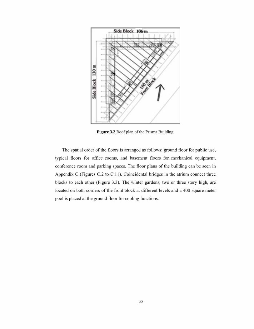
55
Figure 3.2 Roof plan of the Prisma Building
The spatial order of the floors is arranged as follows: ground floor for public use,
typical floors for office rooms, and basement floors for mechanical equipment,
conference room and parking spaces. The floor plans of the building can be seen in
Appendix C (Figures C.2 to C.11). Coincidental bridges in the atrium connect three
blocks to each other (Figure 3.3). The winter gardens, two or three story high, are
located on both corners of the front block at different levels and a 400 square meter
pool is placed at the ground floor for cooling functions.

56
Figure 3.3 Interior view from the atrium showing the bridges
The exterior glass skin, with its louvers rises up the double-skin façade and
extends beyond the roof to cover the atrium. Interior skin i.e. the warm façade is
composed of modular panel systems. There is a 120 cm walking space between the
two skins, and the exterior pane is suspended onto the interior skin with the help of
galvanized steel brackets. For maintenance and cleaning purposes an 80 cm wide
square galvanized steel grill formed like a catwalk assembled on the steel brackets,
are also functioning as shading devices. As seen in Figure 3.4 there are ventilation
flaps that can be opened manually as well as by BMS on the interior pane. User
control is given to the office rooms so that the feeling of being controlled fully by the
building management systems is diminished.
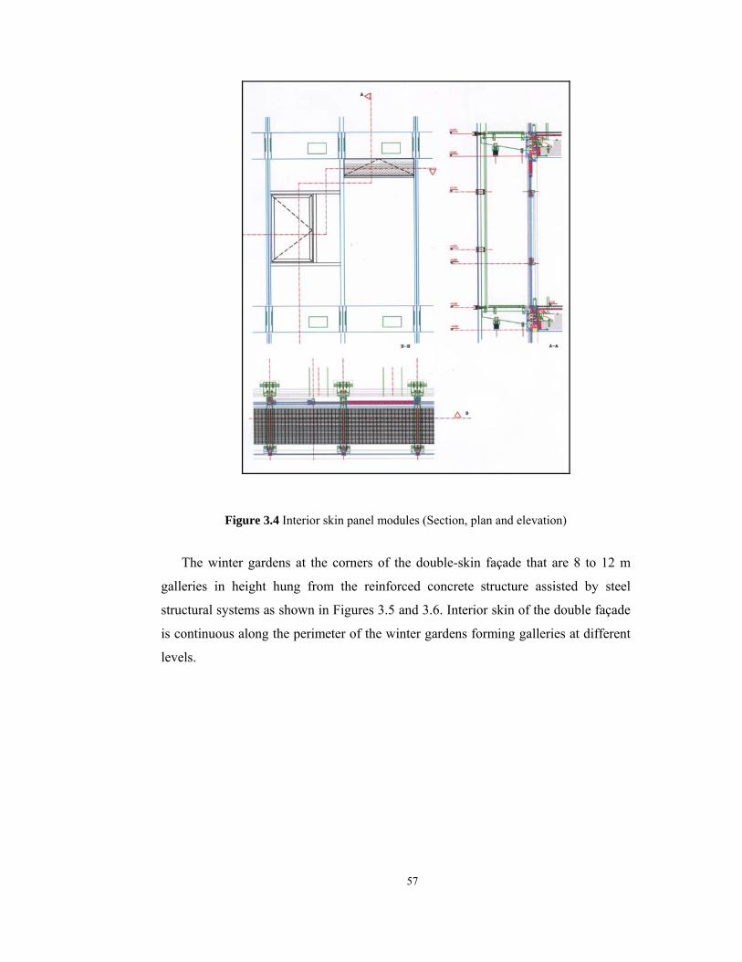
57
Figure 3.4 Interior skin panel modules (Section, plan and elevation)
The winter gardens at the corners of the double-skin façade that are 8 to 12 m
galleries in height hung from the reinforced concrete structure assisted by steel
structural systems as shown in Figures 3.5 and 3.6. Interior skin of the double façade
is continuous along the perimeter of the winter gardens forming galleries at different
levels.

58
Figure 3.5 Corner of the double-skin façade showing the winter garden
Figure 3.6 View from the corner
The ventilation channels connected to the air conditioning system are located
behind the warm façade panels within the concrete slabs. These channels distribute

59
the warmed or cooled air from the cavity to the interior spaces through the flaps,
which are activated by the signals sent from the BMS. The vents on the exterior skin,
which are grouped in different configurations, are also electronically activated
according to the internal and external environmental conditions by the BMS.
Moreover, the perforated aluminum Venetian blinds in the intermediate space is
rotated by the BMS depending on the intensity of the light. A section of the cavity
within the double façade showing details of the ventilation system and the Venetian
blinds is illustrated in Figure 3.7.
Figure 3.7 Section detail from the cavity
In case of fire, if smoke-exhausting case is required, the exterior vents of the
pertinent zone exhaust the smoke by opening completely and at the same time the
sliding panels in the cavity close and act as smoke barriers to isolate the fire.
Furthermore, these vents are programmed to open in order to create airflow in the
cavity on sunny days to cool the air inside the DSF and prevent the warming up of
the interior skin thus reducing the building’s cooling loads and expenditure. A
module with vents that open and close by electronic motors is shown in Figure 3.8.
Figures E.1 to E.7 in Appendix E show various panel modules with different
configurations and Figures E.8 and E.9 illustrate grouped vents from different
locations of the double skin façade.

60
Figure 3.8 Double skin façade modules
Various sensors are present at different locations of the building to analyze the
environmental conditions and to send data to the BMS; these sensors are placed at
different levels in the hall, rooms and atrium to collect the data about temperature,
wind strength, wind direction, solar angle, pressure, and humidity. There are also
sensors in the double façade to measure the humidity, airflow rate, temperature, and
CO2 amount in the cavity of the DSF.
3.2.2. Façade Composition
The 160-meter long and 41 meter high double skin façade facing the southeast
direction is located on a very busy road in Frankfurt as seen in Figure 3.9. The
simulation tests and models for energy, sound reduction, view, and transparency as

61
well as daylight concepts vis-à-vis the location and dimension helped to configure
the composition of the façade.
Figure 3.9 Front view of the double skin façade
The levels and the locations of the vents were determined in accordance with
the simulated model in order to provide an efficient façade and to create a stack
effect by proper air circulation. The location of the inlets and outlets can be seen in
Appendix D in Figures D.1 and D.2. The façade openings are controlled by the BMS.
The section drawing of the cavity showing the relation of the vents is seen in Figure
3.10. The company that designed the façade incorporating energy concepts as well as
comfort conditions of the occupants used different simulation tools to obtain the
optimum results. Their primary goals were minimizing the energy demand,
optimizing the thermal and visual comfort, utilizing natural resources. One of the
design team members declared in his e-mail that they have been monitoring the BMS
operation for over a year and fixing the problems that have been identified.33
33 Alexander Knirsch, The Transsolar Energy Technique Company, [email protected], Retrieved July, 14, 2003.

62
Figure 3.10 Bottom opening vents controlled by motors electronically
The production drawings and details of the double skin façade, along with the
structural calculations and specifications were prepared according to the bylaws and
standards of the German (Hessen) Ministry of Economy, Traffic and Public
Development. The subcontractor company, who prepared these drawings, produced a
life size model mock-up (Figure 3.11), which was tested for thermal and air
infiltration, wind pressure, water and bi-axial earthquake resistance. The k-value was
found to be 1.79 W/m²K as well as sound insulation was found to be less than 39 dB.

63
Figure 3.11 Life size mock-up
The glass properties specified by the Hessen Ministry of Economy, Traffic
and Public Development regulations were as follows: double-skin façade exterior
pane is 10 mm tempered glass and the interior pane stratifies as; tempered glass (8
mm)+ air space (16mm)+ float glass (4 mm) + 0.76 PVB + float glass (4 mm). There
were different glass types in different locations varying to a very large extent from
the point of view of structural properties, wind loads, requested architectural, visual,
acoustical as well as thermal properties, function of the spaces that the glass would
be used. Glass types of the exterior skin can be seen in Appendix D Figure D.3.
The double skin façade is continuous over the building height. According to
North American typologies it is called a twin face façade and according to British

64
typologies it is contained in Category B type 2, which is “openable outer and inner
skin with full building height”. The benefits of this system include its easy
construction with paneled system and better acoustic and thermal performance.
However, this type of construction also has its drawbacks. In summer, the natural
ventilation principle only works for lower floors, as the heat transmitted to the
windows on lower floors is then drawn into the open windows on upper floors.
Therefore, during summer season it is impossible to open windows on upper floors
nevertheless vertical glass partitions have been designed to lessen this effect.
The single glass partitions divide the façade into six zones to prevent the
spread of smoke in case of fires; detail of which are shown in Figure 3.12. These
breaks in the exterior skin allow fresh air to circulate inside the air gaps throughout
these zones. This phenomenon increases the air circulation and the quantity of fresh
air, as air no longer circulates through the entire façade. With this system, all the
disadvantages of the continuous double-skin façade are abolished but it is more
expensive and more difficult to construct compared to other typologies. Moreover,
façade configurations have to be tested in order to choose the one with the most
efficient air circulation, which adds to the design costs.
Figure 3.12 Single glazed glass partition detail
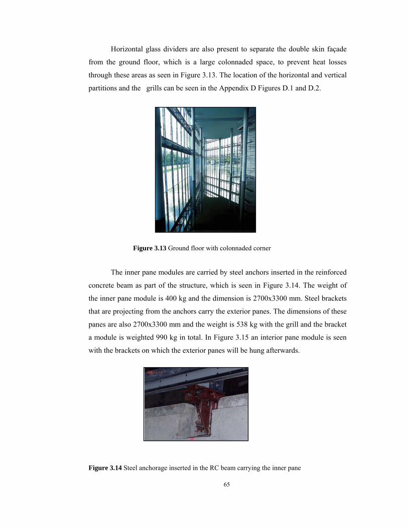
65
Horizontal glass dividers are also present to separate the double skin façade
from the ground floor, which is a large colonnaded space, to prevent heat losses
through these areas as seen in Figure 3.13. The location of the horizontal and vertical
partitions and the grills can be seen in the Appendix D Figures D.1 and D.2.
Figure 3.13 Ground floor with colonnaded corner
The inner pane modules are carried by steel anchors inserted in the reinforced
concrete beam as part of the structure, which is seen in Figure 3.14. The weight of
the inner pane module is 400 kg and the dimension is 2700x3300 mm. Steel brackets
that are projecting from the anchors carry the exterior panes. The dimensions of these
panes are also 2700x3300 mm and the weight is 538 kg with the grill and the bracket
a module is weighted 990 kg in total. In Figure 3.15 an interior pane module is seen
with the brackets on which the exterior panes will be hung afterwards.
Figure 3.14 Steel anchorage inserted in the RC beam carrying the inner pane

66
Figure 3.15 Interior pane module
3.2.3. Design decisions
While designing the façade the design team that computed the simulations took
into consideration several points in order to reach the optimum performance for the
entire building. Among these points four were significantly affecting the overall
performance such as, thermal comfort, double-skin façade, the earth canal and the
limitation of the summer temperatures. These factors are explained in detail in the
following pages.
i. Thermal Comfort
Satisfaction of the users, activities that took place in that particular space and
daily conditions were taken into account for the thermal comfort. Moreover,
particular aspects such as temperature ratios, air change rates, airflow, pressure and
light ratios were considered. Natural ventilation and daylight quality are examined to
provide these conditions.
67
ii. Double-skin façade
The DSF offers among other things following advantages such as; lesser
demands on the interior façade, sun protection, improvement of sound protection,
window ventilation in and out of the double façade, durable night-time ventilation for
the summer overheat of the building, reduction of the energy consumption. In order
to avoid overheating in the summer, the double façade with corresponding openings
or flaps, opened above and below, uses the stack effect for heat reduction and natural
ventilation. At the same time 100-200 fold air change rate can be reached in the
cavity. The decisive interval behind the exterior glass façade becomes by means of a
well reflecting sun protection for solar radiation hitting on the glass façade. The
absorbed solar radiation is ventilated immediately from the double façade area by the
high air changes and therefore does not arrive into the offices.
iii. Earth canal
The earth canal represents an alternative to a conventional cooling. In
summer, the temperature lies in approximately 10°C for the soil. According to depth,
the temperature degree varies. The earth canal lies 10 meters below the ground
surface in the building. The simulation results showed that in an outside temperature
of 33°C the temperature of the air given in the building through the earth canal is
measured as 28.5°C. A heat exchanger is present at the mouth of the earth canal to
cool or warm the air more if necessary.
iv. Limitation of the office temperature in summer
In night hours, the building mass cools off itself with fresh nighttime
ventilation. To obtain the necessary air change rates for the nighttime ventilation,
thermal ventilation is induced or stacked ventilation is required. Airflow through the
façade flows over the top vents of the hall partition into the atrium. Through the flue,
a slight low pressure emerges in the hall due to flowing air taken away over the roof.
By means of the extent ventilation, sufficient air change rate for excessive heat
removal in summer and cooling off the building mass at night hours can be obtained.

68
3.3. Energy management systems
For concept development and estimation the design team defined the following
goals such as, optimization of thermal and visual comfort, avoidance of wind effects
from the façade, avoidance of reflection, protection of summer overheating,
minimization of energy consumption and minimization of operation and initial costs.
Therefore, the design team has determined to create transparent areas for a passive
utilization of solar radiation, maximize exposure to nature, integrate a natural
ventilation concept, utilize natural sources as much as possible (ground cooling,
evaporative cooling) and maximize passive solar gains while minimize the
transmission heat losses.
3.3.1. Winter Operation
During the winter season when outside temperatures fell below -5ºC the
building remains at 20ºC for the side blocks and the front block while the atrium has
a temperature of 16ºC. The air circulation inside the building and the temperature
variations are shown in Figure 3.16. As it is seen in the schematic drawing the side
block is heated through the earth canal whereas the front block is heated by virtue of
the double skin façade.
Figure 3.16 Winter operation in the building
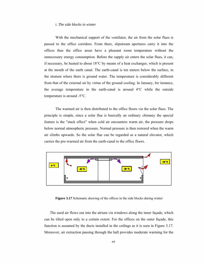
69
i. The side blocks in winter
With the mechanical support of the ventilator, the air from the solar flues is
passed to the office corridors. From there, slipstream apertures carry it into the
offices thus the office areas have a pleasant room temperature without the
unnecessary energy consumption. Before the supply air enters the solar flues, it can,
if necessary, be heated to about 18°C by means of a heat exchanger, which is present
at the mouth of the earth canal. The earth-canal is ten meters below the surface, in
the stratum where there is ground water. The temperature is considerably different
from that of the external air by virtue of the ground cooling. In January, for instance,
the average temperature in the earth-canal is around 4°C while the outside
temperature is around -5°C.
The warmed air is then distributed to the office floors via the solar flues. The
principle is simple, since a solar flue is basically an ordinary chimney the special
feature is the "stack effect” when cold air encounters warm air, the pressure drops
below normal atmospheric pressure. Normal pressure is then restored when the warm
air climbs upwards. So the solar flue can be regarded as a natural elevator, which
carries the pre-warmed air from the earth-canal to the office floors.
Figure 3.17 Schematic drawing of the offices in the side blocks during winter
The used air flows out into the atrium via windows along the inner façade, which
can be tilted open only to a certain extent. For the offices on the outer façade, this
function is assumed by the ducts installed in the ceilings as it is seen in Figure 3.17.
Moreover, air extraction passing through the hall provides moderate warming for the

70
atrium without any additional power input, which is the heat recovery principle.
Basically this means that the building recovers the heat, which it had previously
released into the offices by way of the earth-canal and the solar flues. In combination
with heat-insulating construction materials, this heat recycling makes a major
contribution to efficient utilization of heat. The glass roof is inclined towards the
front block section of the building in order to facilitate the flow of the heated air and
its exit from the top of the double façade, due to its stack effect.
ii. The front block in winter
Cold fresh air from outside enters the DSF, where it is pre-heated by the heat
of the sun entering through the outer glass façade. In addition, the double-glazing
offsets any heat losses due to its interior skin. The principle here, same as the side
block sections, which is, heat recovery: the warmed-up air flows into the offices. In
the rooms facing the outer façade, it does so by means of tilted windows. The used
air escapes through a ventilation duct installed in the ceiling and flows out into the
atrium. In the offices facing the atrium, the principle is reversed. Air enters these
offices through ducts in the ceiling. After circulating, it flows out towards the atrium
via the tilted windows (Figure 3.18).
Figure 3.18 Schematic drawing of the offices in the front block during winter
Finally, the used air is conducted out of the building by the way of the atrium
through the top of the front block. The heat of the sun, passing through the glass roof,

71
contributes to warming the atrium. The open water areas in the building serve to
provide the atrium with humidity and improve the microclimate in the hall.
Consequently the internal environment is balanced with respect to air temperature,
air pressure and air humidity.
3.3.2. Summer Operation
Temperature variations are seen during the summer season when outside
temperatures are around 32°C in Figure 3.19. Inside the building the temperature
remains at 28°C whereas the atrium ranges 26°C to 29°C. The airflow is indicated
with the arrows to demonstrate the air circulation in the building. The hot air is
exhausted through the solar flues for the offices in the side blocks while for the
offices in the front block it is removed from the top vents of the DSF. Finally the
used air follows a path through the atrium and reaches to the outside from the top of
the DSF by using the natural stack effect. The outlet vents and the louvers of the
glass roof are automated by the BMS.
Figure 3.19 Summer operation in the building
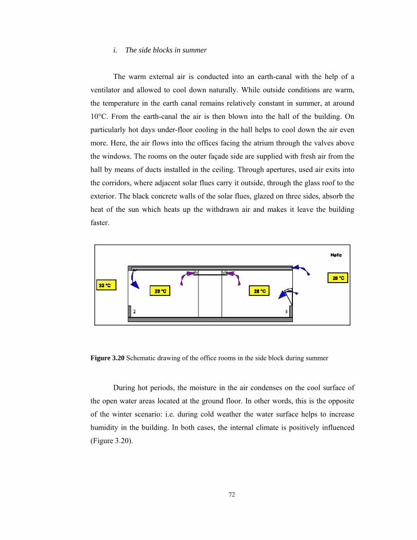
72
i. The side blocks in summer
The warm external air is conducted into an earth-canal with the help of a
ventilator and allowed to cool down naturally. While outside conditions are warm,
the temperature in the earth canal remains relatively constant in summer, at around
10°C. From the earth-canal the air is then blown into the hall of the building. On
particularly hot days under-floor cooling in the hall helps to cool down the air even
more. Here, the air flows into the offices facing the atrium through the valves above
the windows. The rooms on the outer façade side are supplied with fresh air from the
hall by means of ducts installed in the ceiling. Through apertures, used air exits into
the corridors, where adjacent solar flues carry it outside, through the glass roof to the
exterior. The black concrete walls of the solar flues, glazed on three sides, absorb the
heat of the sun which heats up the withdrawn air and makes it leave the building
faster.
Figure 3.20 Schematic drawing of the office rooms in the side block during summer
During hot periods, the moisture in the air condenses on the cool surface of
the open water areas located at the ground floor. In other words, this is the opposite
of the winter scenario: i.e. during cold weather the water surface helps to increase
humidity in the building. In both cases, the internal climate is positively influenced
(Figure 3.20).

73
ii. The front block in summer
The only difference for the front block is in the method of air extraction; here
this is through the double-skin façade. Insolation (the impact of hot sunshine)
through the glass roof is prevented by means of the sun-protection louver blades,
which are rotated by the BMS. This prevents the building from becoming too hot. On
extra hot days during the summer, the building has to be cooled down at night. An
increased air-exchange rate ensures that the building is kept pleasantly cool.
Hall
DSF
Figure 3.21 Schematic drawing of the offices in the front block during summer
3.4. Simulation study
Improved comfort and acoustics, better interior air quality and increased energy-
efficiency have been obtained by the simulation studies, reported field studies and
monitored studies. For this reason, building simulation software programs have been
used to predict the day lighting and solar heat gains as well as hydraulic performance
of the building and in addition as required, a full-scale mock-up was constructed,
tested and evaluated. Three types of simulation studies were carried out which are
presented in the following paragraphs.

74
3.4.1. Simulation tools
Methods used for the simulation of the office building are as follows:
i. Thermal simulation: For the thermal simulation analyses a dynamic
simulation program TRNSYS (Transient system simulation) was used. The
calculation of the dynamic thermal behavior of building envelope was conducted by
TRNSYS through the transfer functions method, which describes the non-stationary
behavior of the building and its components. The advantage was that before the
building was constructed, detailed prediction regarding the thermal behavior and
comfort expectation have been provided as well as heating and cooling requirements
have been predicted.
ii. Hydraulic simulation: The hydraulic simulation was done through the
software COMIS (Conjunction of Multizone Air infiltration Specialist) to determine
air change rate and pollution dispersion in the building.
iii. Air flow simulation: The investigations for the thermal behavior of the
buildings were done through the software FIDAP to provide the average room
temperatures and determine the temperature distributions. In Figure 3.22 and 3.23 the
principle representation of the ventilation concept in summer and winter situations
are shown that are resulted by thermal simulations together with hydraulic
simulations.
Figure 3.22 Principle representation of the ventilation concept during winter

75
Figure 3.23 Principle representation of the ventilation concept during summer
iv. Daylight simulation: Determination of the daylight situation in the atrium, and
in the office rooms has been done with the simulation program called RADIANCE.
Statements on the visual comfort in the atrium and the office rooms have been
encountered through the simulation study. Thereupon the outlines were changed
indicating that wet cells and tea kitchens were shifted into the building corners as
well as a combined direct light and shadowing system was designed above the glass
roof.
v. Daylight measurement with the 1:100 scale model: Determination of daylight
percentage in the atrium and the office rooms have been done with a 1:100 model
under an artificial sky in a laboratory. Visualization of the light ratios in the atrium
was simulated through the model as seen in Figure 3.24.

76
Figure 3.24 Visualization of the light ratios in the atrium under overcast sky conditions
vi. Comfort measurement with the life-size model: Determination of all
comfort parameters was done by means of a life-size model as shown in Figure 3.25.
Comfort measurements of an office room oriented to the double skin façade were
carried out in the field study.
Figure 3.25 Representation of 1:1 section model

77
3.4.2. Results of the Simulations
A simulation period has been selected by 6 weeks (beginning of January until
middle February) in order to document the most unfavorable case for an extreme
weather situation for the dynamic simulation. The air change rates as well as internal
heat loads were found and the results are represented in Table 3.1.
Table 3.1 Survey of some conditions for the building simulations
Description Internal gains by light, persons and electric devices (1 PC per person)
10 W/ms²/ as required 1 person/ 15 ms² office area
120 W/ 15m² office area Utilization time 8.00 – 18.00 clock (heated) Room Temperature (working hours) Night reduction
22 °C 15 °C
Air change rate 1-fold during the utilization times [1/h]
Calculations have been done also for the double skin façade to determine the
temperatures in the cavity in order to find out if it was necessary to design in story
manner separation or to avoid separation. This diminished the initial costs for the
façade and allowed the regulation of the inlets and outlets. A simulation was done
with the extreme heat period about 14 days between the hours 8 am to 8 pm in
middle of May and temperatures were determined within the façade interval as
represented in Figure 3.26. It was seen that there was only a slight dependence of the
temperatures over the height. On the other hand, the temperatures approached each
other during afternoon at the environment temperature because the cool air arrives
out of the offices into the double façade and this results in a decrease in the cavity
temperature.

78
Figure 3.26 Double façade temperatures over the height on the southeast side after a 14-day
heat period
The simulations also showed that the offices independent of their situation and
orientation remained clearly under environment temperature during extreme outside
temperatures (>30°C) by means of ventilation out of the offices to the hall together
with the night cooling of the building mass and there was a slight difference in the
temperatures for the offices in different stories (Figure 3.27).
558
157
40
0
0
0
370
155
50
20
3
526
162
45
0
0
0
397
25
12
676
190
659
90
0 100 200 300 400 500 600 700 800
T>25°C
T>26°C
T>27°C
T>28°C
T>29°C
T>30°C
TEM
PER
ATU
RE
[C°]
TIME [h]
Upper story offices oriented to the DSF / Measured weather data
Upper story offices oriented to the DSF /Statistical weather data
Middle story offices oriented to the DSF /Measured weather data
Middle story offices oriented to the DSF /Statistical weather data
Figure 3.27 Temperatures for the southeast offices with statistical and measured weather
data

79
111
14
0
0
0
0
195
82
24
8
0
0
274
98
11
0
0
0
348
195
88
26
11
0
0 50 100 150 200 250 300 350 400
T>25°C
T>26°C
T>27°C
T>28°C
T>29°C
T>30°C
TEM
PER
ATU
RE
[C°]
TIME [h]
Upper story offices oriented to the hall /Measured weather data
Upper story offices oriented to the hall/ Statistical weather data
Middle story offices oriented to the hall /Measured weather data
Middle story offices oriented to the hall/ Statistical weather data
Figure 3.28 Temperatures for the offices oriented to the hall with statistical and measured
weather data
On the other hand, Figure 3.28 illustrating the offices oriented to the hall has
shown that considerable temperature differences occurred in the offices as the floors
goes up. Based on the temperature stratification in the hall, also the temperature of
the office stories increased over the height; especially the eleventh story was
noticeably hot due to the excessive heat in the roof area. Here a supportive cooling
element was planned which was the ventilation through the double façade by means
of stack effect.
A reason for the integration of the hall into the blocks was to minimize the hall
area and thus the energy consumption of the building, and to increase thermal
comfort, especially in winter, because the offices oriented to the hall had clearly
higher air temperatures and therefore more comfortable conditions. During the
summer season the temperature of the hall was obtained lower than the exterior
temperatures by means of renewable cooled air together with the evaporative cooling
by virtue of open water areas. The simulation results showed that 30% reduction in
energy consumption was obtained with the DSF and the entire concept saved about
50% energy in the building. Airflow simulation results can be found in Appendix G.

80
To stabilize the air temperatures the following design parameters were
incorporated in the building:
i. Ventilation concept
Ventilation of the building functions was designed to be self-sufficient
throughout the year. In unfavorable weather conditions incoming air led over an
earth canal which is supported by a mechanical system. In order to provide natural
ventilation and airflow through the building, the required pressure differences are at
times produced mechanically. However since this system operates only in extreme
conditions the energy consumption is minimized.
ii. Heat requirement
Through compact design, in combination with “intelligent” ventilation of the
building, the annual heat requirement of the building was reduced 30% compared to
the same building with conventional facade.
iii. Comfort conditions of the hall
The simulations showed that in winter, the hall was comfortably tempered
without additional heating. In summer, the atrium hall forms a “cool kernel” for the
building, out of which the offices are served with fresh air, hence throughout the year
comfort conditions are adjusted automatically in the hall.
iv. Comfort conditions of the offices
The offices showed relatively comfortable conditions all year around. The
heating of the rooms with static heat areas created uncertainties in winter for
comfortable temperatures and allowed user control. When the system is used
efficiently, room temperatures remain comfortably below 30°C when outside
temperatures are around 33°C. An effective zoning of the rooms was achieved and
the nighttime ventilation of the building was controlled by mechanically. In areas
where the compliance of these temperatures was not possible like the conference
room, building corners, etc. the system was supported with a component cooling.
Cold air that is withdrawn by means of the heat exchanger at the mouth of the earth
canal serves to cool the building envelope. In case the building had not been air
conditioned during the summer, maximum temperatures still would not rise 1°C to
2°C higher than the required comfort conditions as stipulated in DIN 1946, which is
27°C.
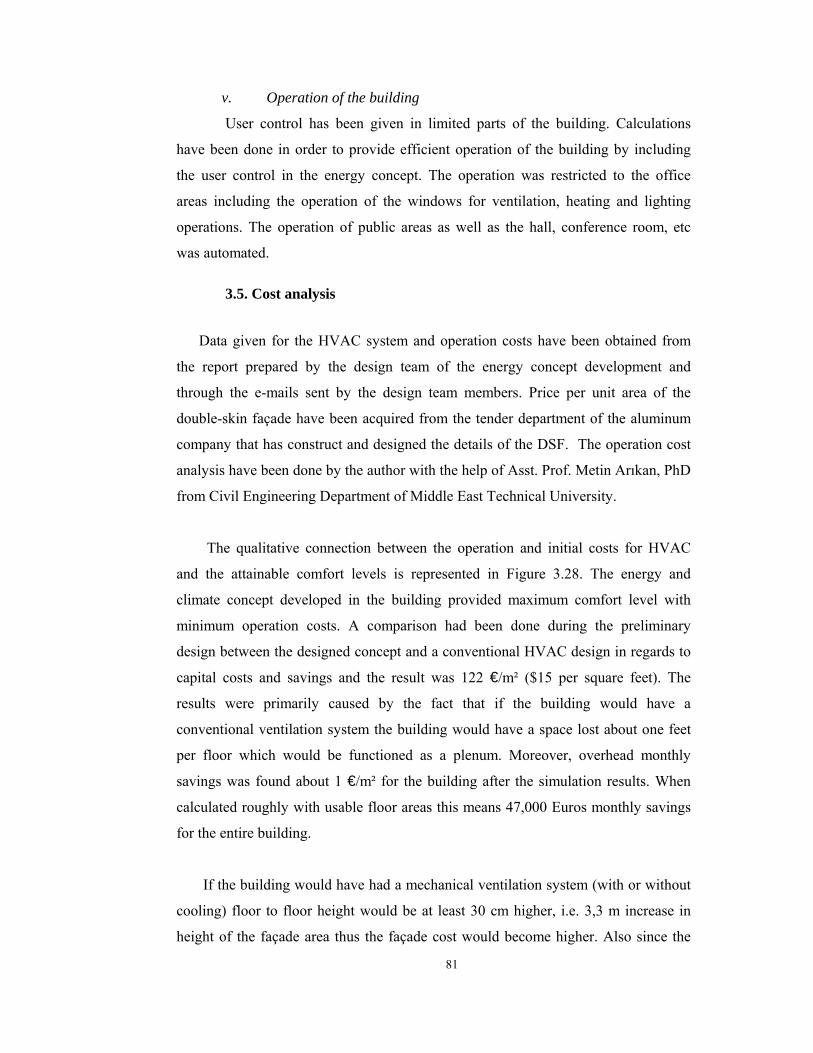
81
v. Operation of the building
User control has been given in limited parts of the building. Calculations
have been done in order to provide efficient operation of the building by including
the user control in the energy concept. The operation was restricted to the office
areas including the operation of the windows for ventilation, heating and lighting
operations. The operation of public areas as well as the hall, conference room, etc
was automated.
3.5. Cost analysis
Data given for the HVAC system and operation costs have been obtained from
the report prepared by the design team of the energy concept development and
through the e-mails sent by the design team members. Price per unit area of the
double-skin façade have been acquired from the tender department of the aluminum
company that has construct and designed the details of the DSF. The operation cost
analysis have been done by the author with the help of Asst. Prof. Metin Arıkan, PhD
from Civil Engineering Department of Middle East Technical University.
The qualitative connection between the operation and initial costs for HVAC
and the attainable comfort levels is represented in Figure 3.28. The energy and
climate concept developed in the building provided maximum comfort level with
minimum operation costs. A comparison had been done during the preliminary
design between the designed concept and a conventional HVAC design in regards to
capital costs and savings and the result was 122 €/m² ($15 per square feet). The
results were primarily caused by the fact that if the building would have a
conventional ventilation system the building would have a space lost about one feet
per floor which would be functioned as a plenum. Moreover, overhead monthly
savings was found about 1 €/m² for the building after the simulation results. When
calculated roughly with usable floor areas this means 47,000 Euros monthly savings
for the entire building.
If the building would have had a mechanical ventilation system (with or without
cooling) floor to floor height would be at least 30 cm higher, i.e. 3,3 m increase in
height of the façade area thus the façade cost would become higher. Also since the
82
roof height was fixed it would mean a loss of one whole floor in the building. There
would also be initial investment for a ventilation system that would have been added
to the total cost of the building. In addition to the gain from the space by preventing
the plenum there was also savings from the suspended ceiling which was around
2,000,000 € which is approximately half of the initial cost of the DSF.
Figure 3.29 Qualitative connections of comfort and costs for HVAC
The cost analysis done by the tender department of the aluminum company
showed that the unit price of the double-skin façade was around 500 €/m² ($55 per
square feet). Since the total area of the DSF is approximately 9900 m² overall façade
had a cost of 4,950,000 €. As the entire building had charged 102,300,000 € which
means that 20% of the total cost was contained by the DSF. At first instance one can
think that the DSF has a considerable fraction in total cost of the building but it must
be remembered that the façade amortizes the high initial cost in long-term. It was
mentioned earlier in the literature survey part that the initial cost of the DSFs range
from 20% to 300% of conventional façades, depending on actual façade composition.

83
The amortization time of the double-skin façade has been calculated by the
author and while doing so the highest cost difference has been considered in which
the DSF has been accepted as 300% higher than the conventional façade. Since the
initial cost of the DSF was found 4,950,000 € it was accepted that if the building
would have had a conventional façade it would cost 1,650,000 € and the cost
difference would be around 3,300,000€. The savings from the operation costs were
taken 1 € /m². The results of the analysis have shown that the amortization time of
the double-skin façade would be 7 years when interest rate was taken as 5% per year
and it would be 9 years if the interest rate has been taken as 10% per year.
Consequently it can be said that the façade pays off the high initial cost in 7 to 9
years. It is certain that this was an oversimplification because there are many other
parameters that should be considered in the amortization calculation some of which
are quantifiable and some are not.
84
CHAPTER 4.
CONCLUSION AND RECOMMENDATIONS
Together with the increase in energy prices, air pollution and decrease in
fossil fuels buildings that are responsive to environmental issues and that have low
energy consumption became important in the building industry. Within the
framework of this study, DSF systems integrated into the intelligent buildings, which
were one of the solutions to the aforementioned concerns, have been examined
through a case study. This chapter presents the conclusions derived from the study
and offers some suggestions for further studies.
The Prisma Building incorporating a southeast oriented DSF that was
integrated into the entire operation of the building was designed to bring solutions to
environmental and ecological problems as well as to create a healthy and
comfortable environment for its occupants. The overall concept was focused on a
low energy consumption along with user satisfaction; hence various methods were
used to reach to the optimum energy performance with minimum energy
consumption. One of the design components was a DSF to provide natural
ventilation as well as to reduce heating and cooling loads of the building. By means
of natural ventilation welfare of the occupants’ was established and also illnesses
related to substandard mechanical ventilation were prevented. Integration of DSF
with the HVAC system provided fresh air intake for the office rooms and removal of
used air from the offices. This phenomenon resulted in a considerable increase in
occupants’ comfort levels and a substantial decrease in heating and cooling loads
was also achieved. Moreover, various components such as an earth-canal for ground
cooling and open water surfaces for evaporative cooling have contributed to
85
the reduction in energy consumption. In addition to a reduction in heating and
cooling loads of the building the pool has served as a humidifier for the building
increasing the humidity during cold and dry periods and decreasing it in hot and
humid conditions. Design components of the building which were used to climatize
the interior environment were all natural resources, such as solar energy, water and
earth-mass; this ensured the maximum utilization of natural resources and, therefore,
minimum consumption of fossil fuels and reduction in unfavorable gas emissions.
The control of building management systems over the design components
according to the interior and exterior conditions positively influenced the efficiency
in terms of energy management operations. The rotation of the perforated aluminum
Venetian blinds in the DSF cavity and louvers on the glass roof; operation of the
sliding panels in the DSF cavity; and ventilation flaps on the exterior and interior
skin of the DSF, have been controlled by BMS signals. This event has contributed to
the optimum use of lighting and ventilation operations thus a reduction in energy
consumption and building operation costs. With the use of DSF capital costs and
savings about 122 €/m² have been obtained compared to a conventional HVAC
concept and overhead monthly savings were found about 1 €/m². This has resulted
in a seven to nine years amortization time for the high initial cost.
On the other hand, problems can occur due to the faulty workmanship: for
example, two years after the completion of the building a breakdown in the
connection between the façade components and BMS occurred and ventilation flaps
could not be opened by the BMS signals. This problem gave rise to an excessive
increase in temperature within the DSF cavity thus comfort conditions could not be
established for sometime. Therefore, careful design and construction have a very
important role in efficient operations. Another disadvantage was the reduction in
available floor areas by approximately 1800 m² which is approximately one whole
floor area. Using the DSF cavity as a fire-escape stair-well diminished this
disadvantage to a certain extent.
Recommendations for future studies
The percentage of energy savings may vary with different construction
86
materials and different configurations of the façade composition. Thus there would
have been thermal performance analyses searching for various alternatives for the
materials used for the façade components to achieve an optimal energy performance.
The emissivity, transmissivity, reflectivity and absorptivity of each pane would have
been investigated from the point of view of materials. For example, for the interior
skin; opaque materials such as aluminum panels, aerated concrete panels, lightweight
sandwich panels or medium density fiberboard (MDF) panels could have been tested
instead of glass panels or different coatings could have been applied to the glazing
units to decrease the thermal transmittance value. Perforated aluminum Venetian
blinds in the DSF cavity functioned as shading devices could have been tested for
various materials regarding their emissivity, absorptivity and reflectivity and also
dimensions and locations of the shading devices could have been experimented. The
glazed roof is also one of the important parts of the building from the point of view
of heat gain and losses. There would have been also experimental studies with
different materials for the glazed roof and the dimension of the louver blades on the
roof. Depth of the DSF cavity, height of the outlet and inlet windows were all
important factors affecting the performance of the DSF, various configurations
should have been examined in these thermal performance analyses.
It is also important to have experiments after the simulation tests to see
whether the results were close to the real world dimensions or not. There has been
life-size mock-up studies on energy performance and comfort levels for the case
study. Although this was a very important step there would have been further studies
after the building has been completed to see the overall performance of the building.
Energy performance analyses could have been done to find out if the airflow in the
building was enough for the cooling and heating operations that were provided by the
earth duct and DSF. Frankfurt has convenient climatic conditions for its day-night
temperature differences most of the year. Weather data has taken from a web site34
and temperatures were found for a period chosen from October 2002 to September
2003. The results showed that the average daily temperature difference is 10°C in a
year-period. Temperature difference reaches its maximum in August and September
which is around 17°C and minimum in November and December which is around

87
4°C. On the other hand solar radiation data obtained from Daniels (1997) and The
Apache Project web site35 shows that high investment costs are disproportionate to
subsequent energy savings since approximately 70% of the radiation occurs from
April to September. Yearly means of daily global clear sky irradiation values were
found 4.57 kWh/m² and for annual sum of radiation it was found 1033 kWh/m² for
Frankfurt. The amortization calculations of solar systems yield better results for
Southern Europe regarding the average global radiation and insolation values. For
the case study the temperature difference was found 25°C during winter on the other
hand it was found only 4°C during summer time. Thus there would have been more
investigations to increase the airflow rate for the summer period to remove the
excessive heat from the building. Another important issue was occupant satisfaction
for the building operations. One of the design team members declared that he
believes that they have achieved a range between 5% to 10% for the dissatisfaction
percentage, i.e. 50 and 100 people are complaining about thermal comfort in 1000
people that work in Prisma Building. Yet there has been no study about the occupant
satisfaction, it would be advisable to make a questionnaire for the occupant
satisfaction, the results of the questionnaire would have been very useful for the
future studies to see whether the comfort levels have been established or not.
Consequently, integrated double skin facade systems offer an innovative
solution for an improvement in energy efficiency in terms of reducing the heating
and cooling loads as well as artificial lighting requirements: such systems depend on
the utilization of natural resources as much as possible thus preventing air pollution
and resource depletion. Although double skin facades seem very expensive
investments for today, these kinds of innovative solutions should be experimented in
which renewable resources utilized as much as possible since fossil fuel reserves are
being exhausted day by day and what is left should be used carefully.
34 The Weather Underground Inc. Web site Retrieved September 14, 2003. http://www.wunderground.com/cgi-bin/findweather/getForecast?query=frankfurt 35 The Apache Project, Integration and exploitation of networked Solar radiation Databases for environment monitoring, Retrieved September 14, 2003, http://prime.jrc.it/SoDa/SoDa.html
88
LITERATURE CITED
Arons, D. M. M. (2000). Properties and Applications of Double-Skin Building Façades (Doctoral dissertation, Master of Science in Building Technology at the Massachusetts Institute of Technology, 2000). OCLC 48022825 Atkin, B. (Ed). (1988). Intelligent Buildings-Applications of IT and Building Automation to High Technology Construction Projects. Worcester: Billings&Sons. Barakat, S.A. (1987). Thermal Performance of a Supply- Air Window. 12th Passive Solar Conference Proceedings, Portland, OR, U.S.A. Barreneche, R. A. (1995). High-Tech Cladding. Architecture. 84 (1), 115-119. Battle, G., McCarthy, C., & Wigginton, M. (2000, June). Retrieved August 02, 2003, from Battle McCarthy Web site: http://www.battlemccarthy.demon.co.uk/research/doubleskin/mainpage.htm Bernaden, A. J., Neabauer R. E., & Johnson Control Inc. (Eds). (1988). The Intelligent Building Sourcebook, Lilburn, GA: Fairmont Press. Bevington, R., & Rosenfeld, A. H. (1990, September). Energy for Buildings and Homes. Scientific American, 263 (3), p.76. Boake, T. M., Harrison, K., Collins, D., Balbaa, T,. Chatham, A., Lee, R., et.al. (2003). The Tectonics of the Double Skin: What are double façades and how do they work?, Retrieved June 14, 2003, from University of Waterloo Web site: www.fes.uwaterloo.ca/architecture/faculty_projects/terri/ds/tectonic.pdf Clements-Croome, D. (2001). Intelligent Buildings for the 21th century, Retrieved August 04, 2003, http://www.agilearchitecture.com Coggan, D. A. How Can Buildings Be Intelligent?. Retrieved July 28, 2003, http://www.coggan.com/buildingintelligence.html
89
Coggan, D. A. Intelligent Buildings Simply Explained. Retrieved July 28, 2003, http://www.coggan.com/aboutintelligent buildings.html Coggan, D. A. Smart buildings. Retrieved July 28, 2003, http://www.coggan.com/smartbuildings.html Compagno, A. (1996). Intelligent Glass Façades, Berlin: Birkhauser. Daniels, K. (1997). The technology of Ecological Building: Basic Principles, Examples and Ideas, Berlin: Birkhauser. Foster and Partners web site, Retrieved 01.Aug. 2003, http://www.fosterandpartners.com Harrison, A., Loe, E. & Read, J. (Eds.). (1998). Intelligent Buildings in Southeast Asia. London and New York: E&FN Spon. Hensen, J., Bartak, M. & Drkal, F., Modeling and Simulation of a Double-Skin Façade System. Retrieved August 04, 2003, http://www.bwk.tue.nl/fago/hensen/publications/02_ashrae_dskin.pdf Hochtief web page, Retrieved January 04, 2003, http://www.prisma.hochtief.de Eleanor, L., Lee, E., Selkowitz, S., Bazjanac, V., Inkarojrit, V., Kohler, C. (2002) High-Performance Commercial Building Façades, Active Load Management with Advanced Window Wall Systems: Research and Industry Perspectives, Retrieved Aug. 02, 2003, http://gaia.lbl.gov/hpbf/main.html Li, S. (2001). A Protocol to Determine the Performance of South Facing Double Glass Façade System-A Preliminary Study of Active/Passive Double Glass Façade Systems. (Master’s Thesis, Virginia Polytechnic Institute and State University, 2001). Etd-04212001-152253 Neubert, S. (1999). Double-Skin Façades – A contribution to Sustainability?, (Master’s Thesis, European Postgraduated Studies in Architecture and Sustainability, 1999).

90
Odell, B. (2002). Energy Efficient Building Design. Retrieved May 14, 2003, from HOK Sustainable Design web site: http://www.hoksustainabledesign.com/news/current Oesterles, E.L., Lieb, R., Lutz, M., and Heusler, W. (2001). Double-skin façades: Integrated planning. Berlin: Prestel. Permasteelisa web site , Retrieved January 14, 2003, http://www.permasteelisa.com.sg/eng/projects/theelicon/theelicon.html Saelens D., and Hens, H.(1997). Case study – Active envelopes, Report 2, Annex32, Integral Building Envelope Performance Assessment, Subtask B, International Energy Agency, Exco Energy Conservation in Buildings and Community systems Programme, (n.d.). Salens, D. and Hens, H. (2002). Energy Performance Assessment of Active Envelopes Building Physics 2002-6th Nordic Symposium (pp. 341-348) Retrieved January 14, 2003, http://www.byg.ntnu.no Saelens, D., Carmeliet, J., and Hens, H. (2003). Energy Performance Assessment of Multiple Skin Façades. International Journal of HVAC&R Research Vol. 9, nr. 2, (pp.167-186). Retrieved June 14, 2003, http:// www.kuleuven.ac.be Schendler, B. R. (1990, Dec.). Even Your Walls Will Have Brains. Fortune, 122 (15), p.16. ‘Smart Buildings’ are Granted a Tax Exemption. (1995, Aug. 18). The New York Times. Space Modulator, Retrieved May 02, 2003, from Nippon Sheet Glass Web site: http://www.nsg.co.jp Straube, J. F., and Straaten R. van. (2001). The Technical Merit of Double Façades for Office Buildings in Cool Humid Climates, Retrieved March 12, 2003, from University of Waterloo Web site: http://www.buildingsolutions.ca The Apache Project, Integration and exploitation of networked Solar radiation Databases for environment monitoring, Retrieved September 14, 2003, http://prime.jrc.it/SoDa/SoDa.html
The Weather Underground Inc. Web site, Retrieved September 14, 2003, http://www.wunderground.com/cgi-bin/findweather/getForecast?query=frankfurt

91
APPENDIX A
Comparative Analysis Tables of a Double-Skin Façade and a Conventional Façade
Deep Plan
Fresh Air Cooling Peak Plant Load (W/m²)
Central Space Requirements
(m²/m²)
Energy (kWh/m²)
Running Costs (£/m²)
Emissions (kgC/m²)
Conventional 28.3 N/A 5.0 0.27 0.70
Double skin sealed cavity, blinds, mechanical fresh air 28.3 N/A 5.0 0.27 0.70
Vented outer skin, blinds, mechanical fresh air 28.3 N/A 5.0 0.27 0.70
Double skin sealed cavity, blinds, mechanical fresh air
extracted via cavity 28.3 N/A 5.0 0.27 0.70
Vented outer and inner, mixed mode 28.3 N/A 3.7 0.20 0.52
Vented outer and inner, natural ventilation 11.7 0.0 2.1 0.11 0.29
Cavity pre heat of fresh air 28.3 N/A 5.0 0.27 0.70
Narrow plan
Fresh Air Cooling Peak Plant Load (W/m²)
Central Space Requirements
(m²/m²)
Energy (kWh/m²)
Running Costs (£/m²)
Emissions (kgC/m²)
Conventional 28.3 N/A 5.0 0.27 0.70
Double skin sealed cavity, blinds, mechanical fresh air 28.3 N/A 5.0 0.27 0.70
Vented outer skin, blinds, mechanical fresh air 28.3 N/A 5.0 0.27 0.70
Double skin sealed cavity, blinds, mechanical fresh air
extracted via cavity 28.3 N/A 5.0 0.27 0.70
Vented outer and inner, mixed mode 28.3 N/A 2.7 0.15 0.39
Vented outer and inner, natural ventilation 0.0 N/A 0.0 0.00 0.00
Cavity pre heat of fresh air 28.3 N/A 5.0 0.27 0.70
Figure A.1 Comparative fresh air-cooling analysis for different façade typologies

92
Deep Plan
Fresh Air Heating Peak Plant Load (W/m²)
Central Space Requirements
(m²/m²)
Energy (kWh/m²)
Running Costs (£/m²)
Emissions (kgC/m²)
Conventional 14.0 N/A 11.7 0.11 0.64
Double skin sealed cavity, blinds, mechanical fresh air 14.0 N/A 11.7 0.11 0.64
Vented outer skin, blinds, mechanical fresh air 14.0 N/A 11.7 0.11 0.64
Double skin sealed cavity, blinds, mechanical fresh air
extracted via cavity 14.0 N/A 11.7 0.11 0.64
Vented outer and inner, mixed mode 14.0 N/A 11.3 0.11 0.62
Vented outer and inner, natural ventilation 14.0 0.0 11.3 0.11 0.62
Cavity pre heat of fresh air 10.0 N/A 5.6 0.06 0.31
Narrow plan
Fresh Air Heating Peak Plant Load (W/m²)
Central Space Requirements
(m²/m²)
Energy (kWh/m²)
Running Costs (£/m²)
Emissions (kgC/m²)
Conventional 14.0 N/A 11.7 0.11 0.64
Double skin sealed cavity, blinds, mechanical fresh air 14.0 N/A 11.7 0.11 0.64
Vented outer skin, blinds, mechanical fresh air 14.0 N/A 11.7 0.11 0.64
Double skin sealed cavity, blinds, mechanical fresh air
extracted via cavity 14.0 N/A 11.7 0.11 0.64
Vented outer and inner, mixed mode 14.0 N/A 11.1 0.11 0.61
Vented outer and inner, natural ventilation 14.0 N/A 11.1 0.11 0.61
Cavity pre heat of fresh air 9.2 N/A 4.4 0.04 0.24
Figure A.2 Comparative fresh air-heating analysis for different façade typologies

93
Deep Plan
Space Cooling Peak Plant Load (W/m²)
Central Space Requirements
(m²/m²)
Energy (kWh/m²)
Running Costs (£/m²)
Emissions (kgC/m²)
Conventional 10.6 51.3 1.9 0.10 0.27
Double skin sealed cavity, blinds, mechanical fresh air 13.2 53.0 1.8 0.10 0.25
Vented outer skin, blinds, mechanical fresh air 2.1 46.0 0.0 0.00 0.00
Double skin sealed cavity, blinds, mechanical fresh air
extracted via cavity 6.8 49.5 0.2 0.01 0.03
Vented outer and inner, mixed mode 0.0 44.3 0.0 0.00 0.00
Vented outer and inner, natural ventilation 0.0 25.0 0.0 0.00 0.00
Cavity pre heat of fresh air 2.1 46.0 0.0 0.00 0.00
Narrow plan
Space Cooling Peak Plant Load (W/m²)
Central Space Requirements
(m²/m²)
Energy (kWh/m²)
Running Costs (£/m²)
Emissions (kgC/m²)
Conventional 23.3 58.5 7.6 0.42 1.08
Double skin sealed cavity, blinds, mechanical fresh air 28.7 64.0 6.4 0.35 0.91
Vented outer skin, blinds, mechanical fresh air 3.7 44.3 0.0 0.00 0.00
Double skin sealed cavity, blinds, mechanical fresh air
extracted via cavity 16.2 53.0 0.4 0.02 0.05
Vented outer and inner, mixed mode 3.7 44.3 0.0 0.00 0.00
Vented outer and inner, natural ventilation 0.0 0.0 0.0 0.00 0.00
Cavity pre heat of fresh air 3.7 44.3 0.0 0.00 0.00
Figure A.3 Comparative space-cooling analysis for different façade typologies
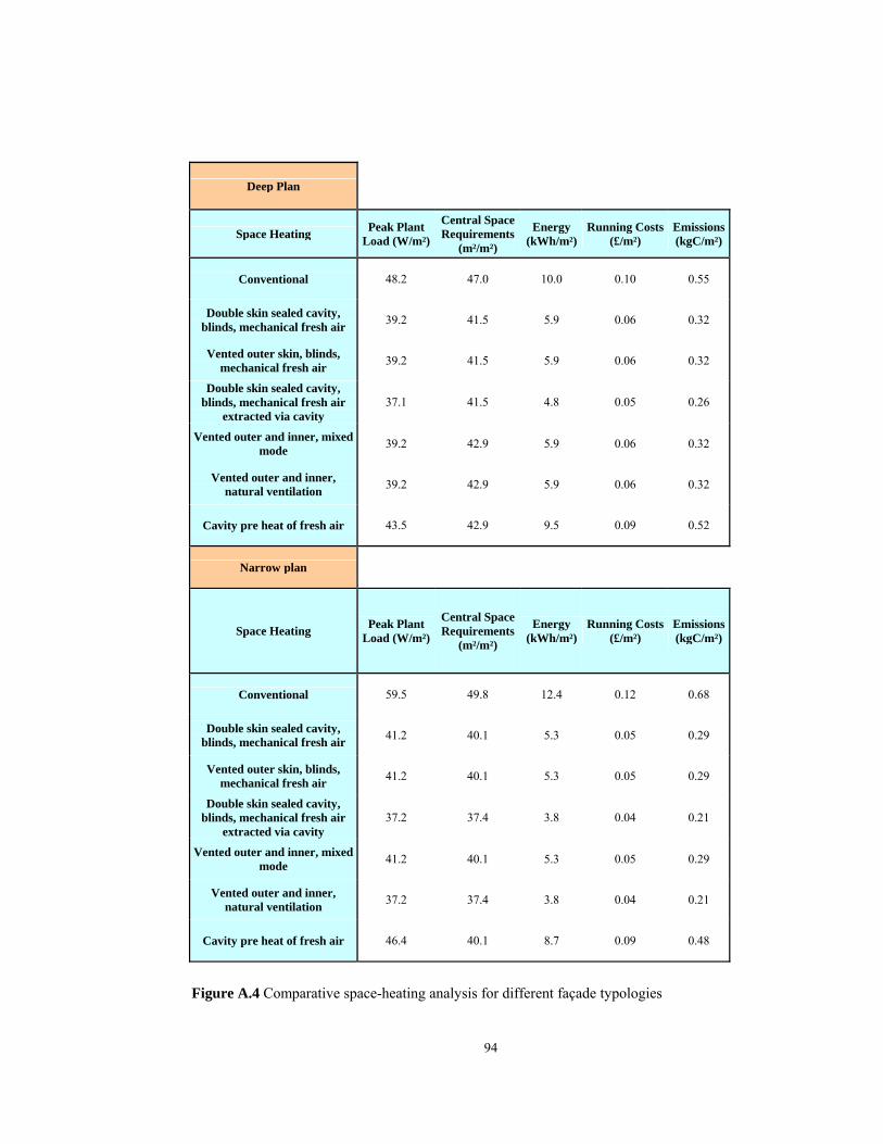
94
Deep Plan
Space Heating Peak Plant Load (W/m²)
Central Space Requirements
(m²/m²)
Energy (kWh/m²)
Running Costs (£/m²)
Emissions (kgC/m²)
Conventional 48.2 47.0 10.0 0.10 0.55
Double skin sealed cavity, blinds, mechanical fresh air 39.2 41.5 5.9 0.06 0.32
Vented outer skin, blinds, mechanical fresh air 39.2 41.5 5.9 0.06 0.32
Double skin sealed cavity, blinds, mechanical fresh air
extracted via cavity 37.1 41.5 4.8 0.05 0.26
Vented outer and inner, mixed mode 39.2 42.9 5.9 0.06 0.32
Vented outer and inner, natural ventilation 39.2 42.9 5.9 0.06 0.32
Cavity pre heat of fresh air 43.5 42.9 9.5 0.09 0.52
Narrow plan
Space Heating Peak Plant Load (W/m²)
Central Space Requirements
(m²/m²)
Energy (kWh/m²)
Running Costs (£/m²)
Emissions (kgC/m²)
Conventional 59.5 49.8 12.4 0.12 0.68
Double skin sealed cavity, blinds, mechanical fresh air 41.2 40.1 5.3 0.05 0.29
Vented outer skin, blinds, mechanical fresh air 41.2 40.1 5.3 0.05 0.29
Double skin sealed cavity, blinds, mechanical fresh air
extracted via cavity 37.2 37.4 3.8 0.04 0.21
Vented outer and inner, mixed mode 41.2 40.1 5.3 0.05 0.29
Vented outer and inner, natural ventilation 37.2 37.4 3.8 0.04 0.21
Cavity pre heat of fresh air 46.4 40.1 8.7 0.09 0.48
Figure A.4 Comparative space-heating analysis for different façade typologies

95
APPENDIX B
Cost analysis of a conventional façade and a double-skin façade in a deep plan
and a narrow plan building
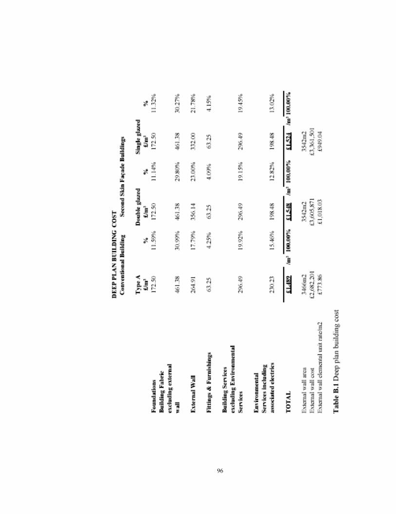
96
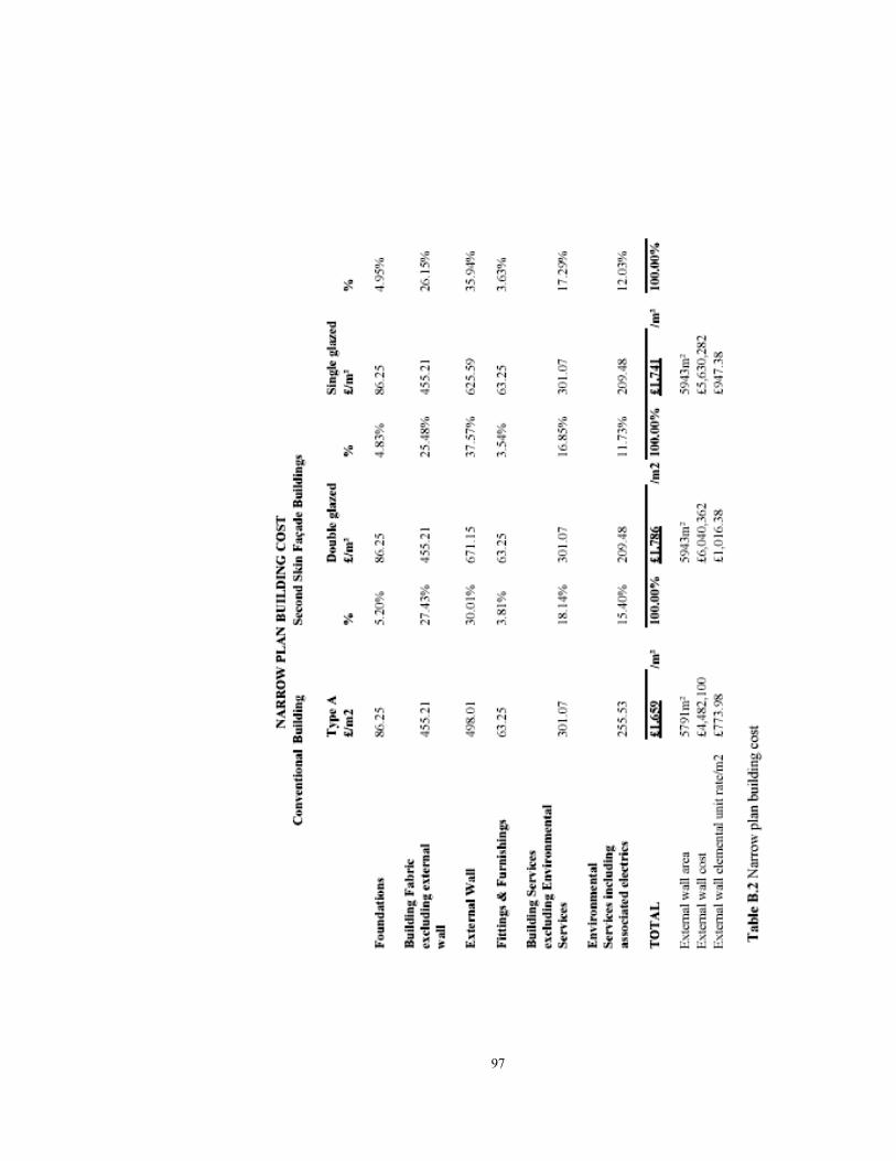
97

98
APPENDIX C
Architectural drawings of the case study
Figure C.1 Site Plan

99
Figure C.2 First Floor Plan

100
Figure C.3 Second Floor Plan

101
Figure C.4 Third Floor Plan
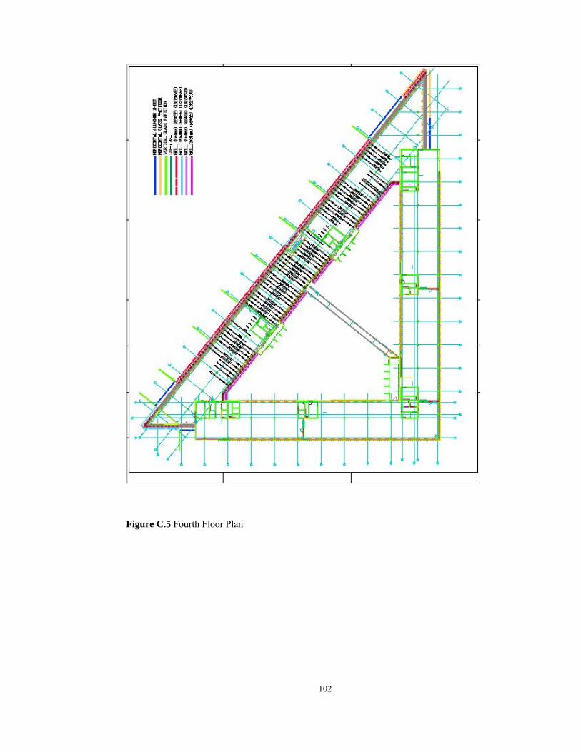
102
Figure C.5 Fourth Floor Plan

103
Figure C.6 Fifth Floor Plan

104
Figure C.7 Sixth Floor Plan

105
Figure C.8 Seventh Floor Plan

106
Figure C.9 Eighth Floor Plan

107
Figure C.10 Ninth Floor Plan
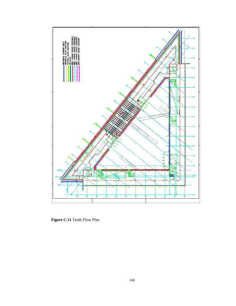
108
Figure C.11 Tenth Floor Plan
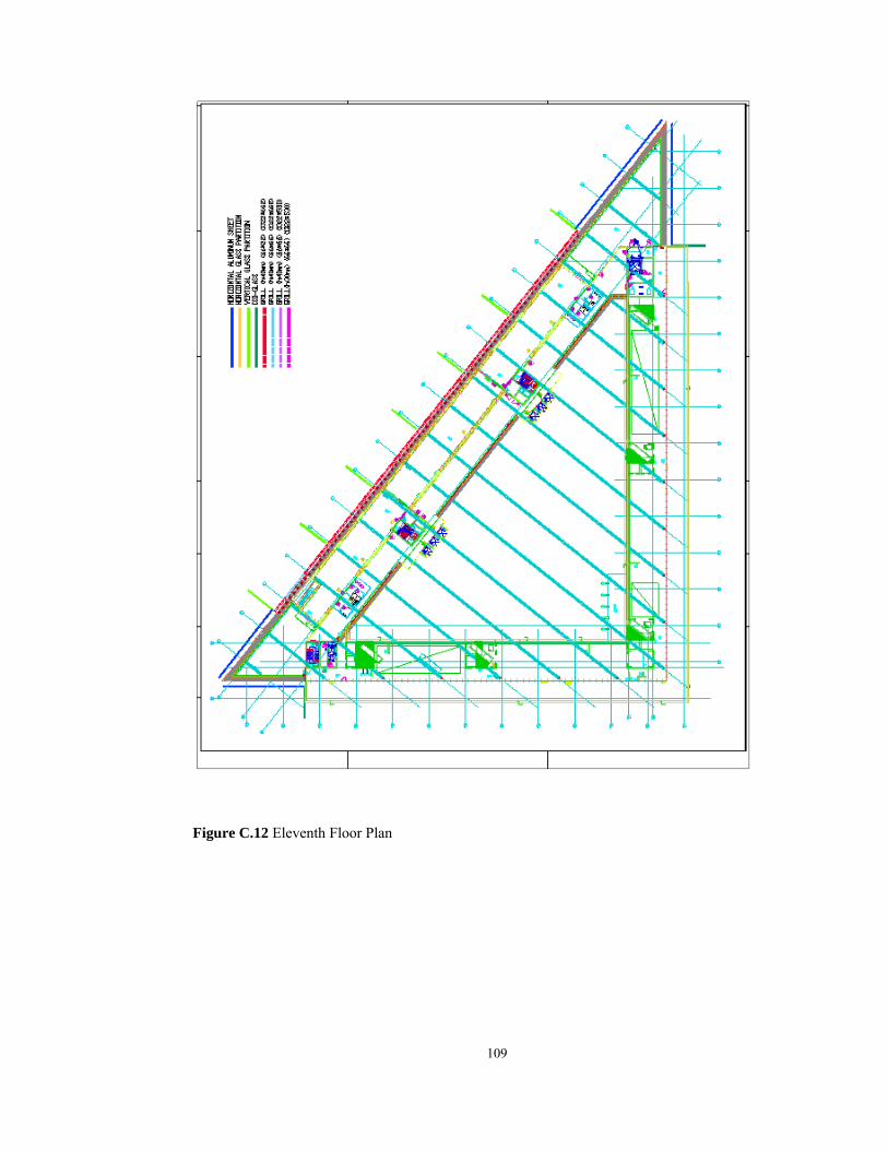
109
Figure C.12 Eleventh Floor Plan

110
Figure C.13 Section through the side block

111
Figure C.14 Section through the front block

112
Figure C.15 Section through the double-skin facade
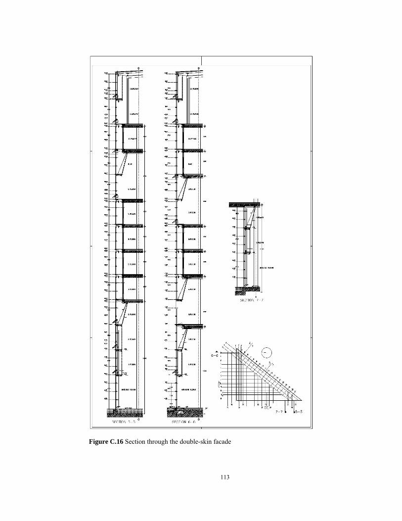
113
Figure C.16 Section through the double-skin facade

114
APPENDIX D
Façade composition showing the façade elements and glass types Figure D.1 Façade composition front view

115
Figure D.2 Façade composition side views

116
Figure D.3 Façade composition showing the glass types
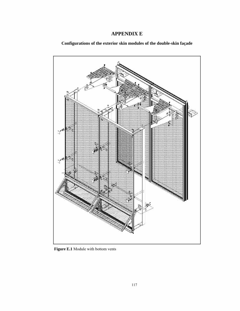
117
APPENDIX E
Configurations of the exterior skin modules of the double-skin façade
Figure E.1 Module with bottom vents

118
Figure E.2 Module without vents

119
Figure E.3 Winter garden panel module

120
Figure E.4 Module with single bottom vent
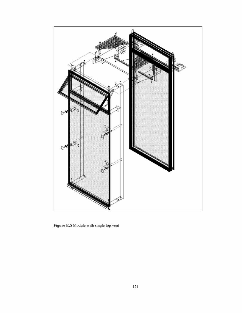
121
Figure E.5 Module with single top vent
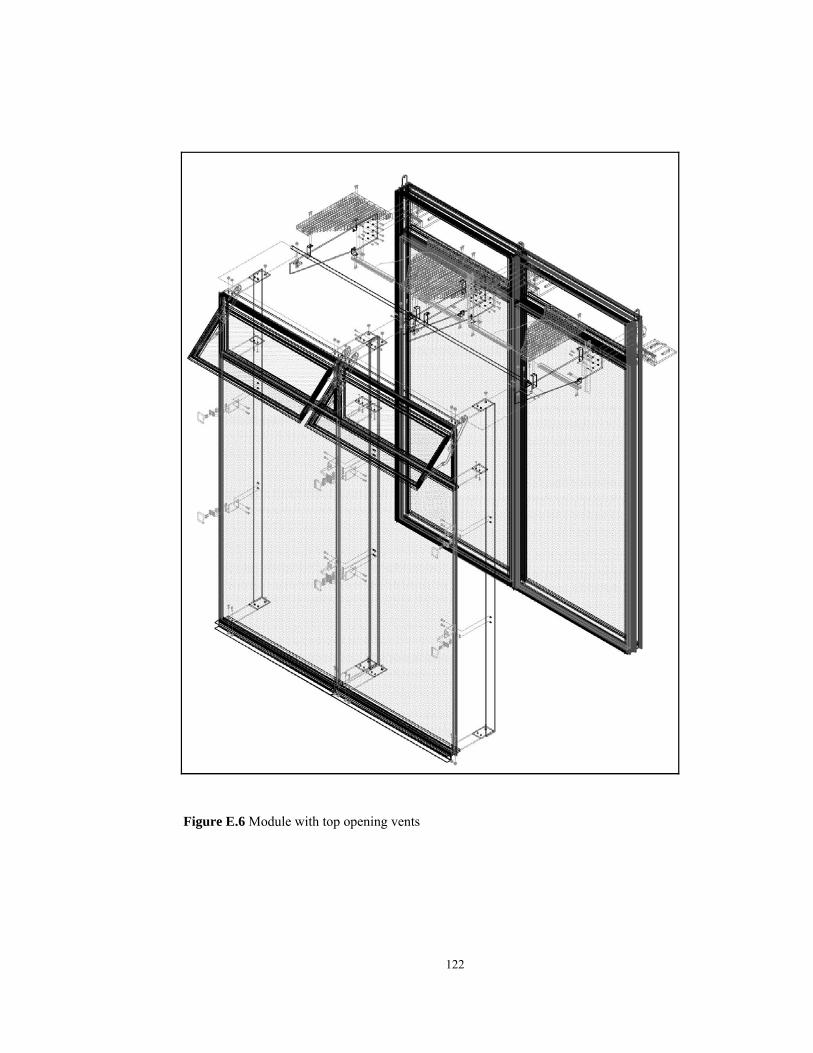
122
Figure E.6 Module with top opening vents
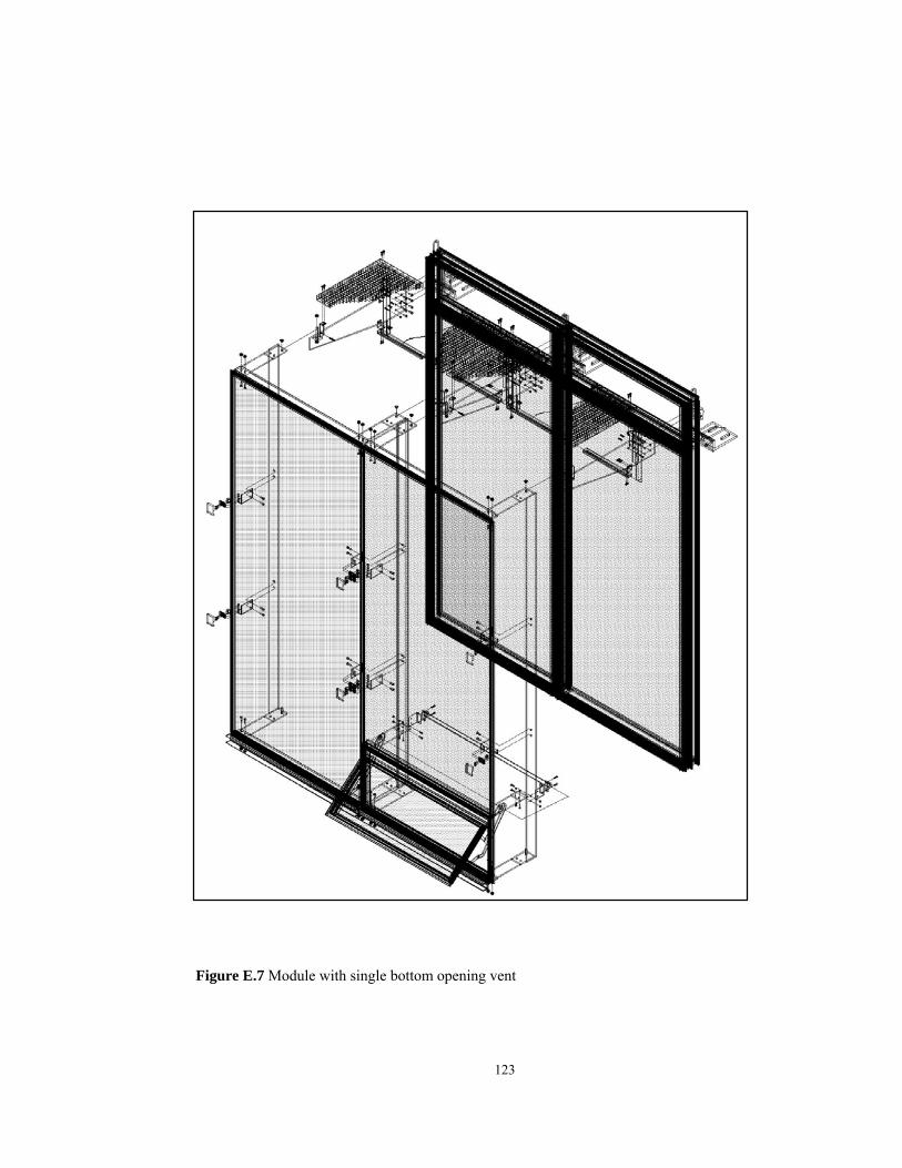
123
APPENDIX H.1
Figure E.7 Module with single bottom opening vent

124
Figure E.8 Grouped vents from different locations of the double skin façade
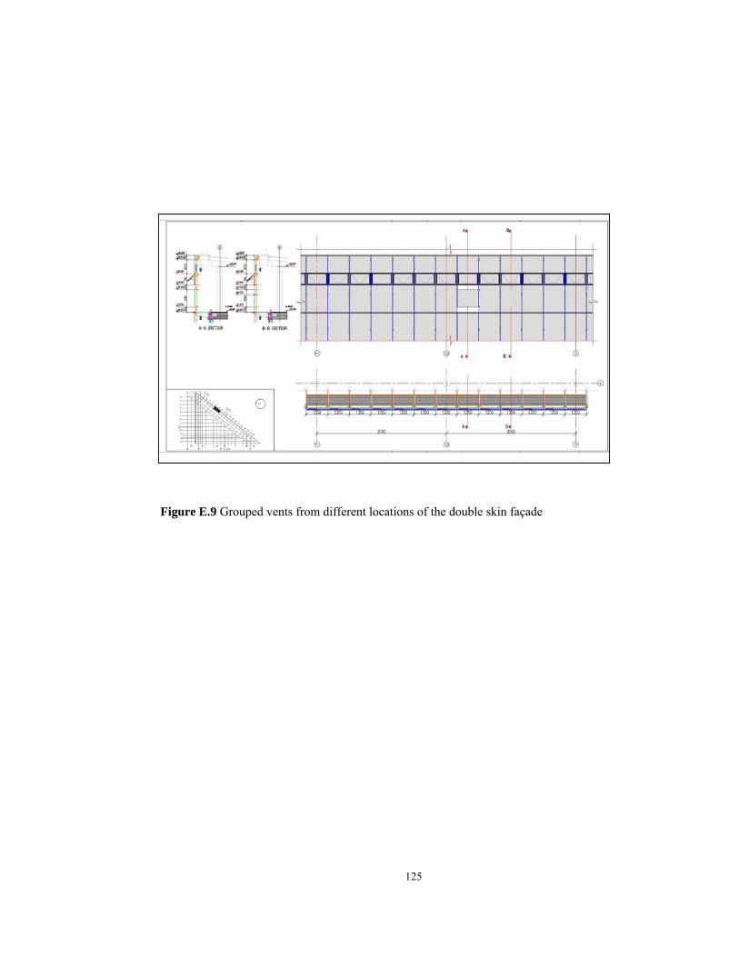
125
Figure E.9 Grouped vents from different locations of the double skin façade

126
APPENDIX F
Images of the Prisma Building
F
igur
e F.
1 In
terio
r vie
w fr
om th
e at
rium

127
Figure F.2 Exterior view of the Prisma Building
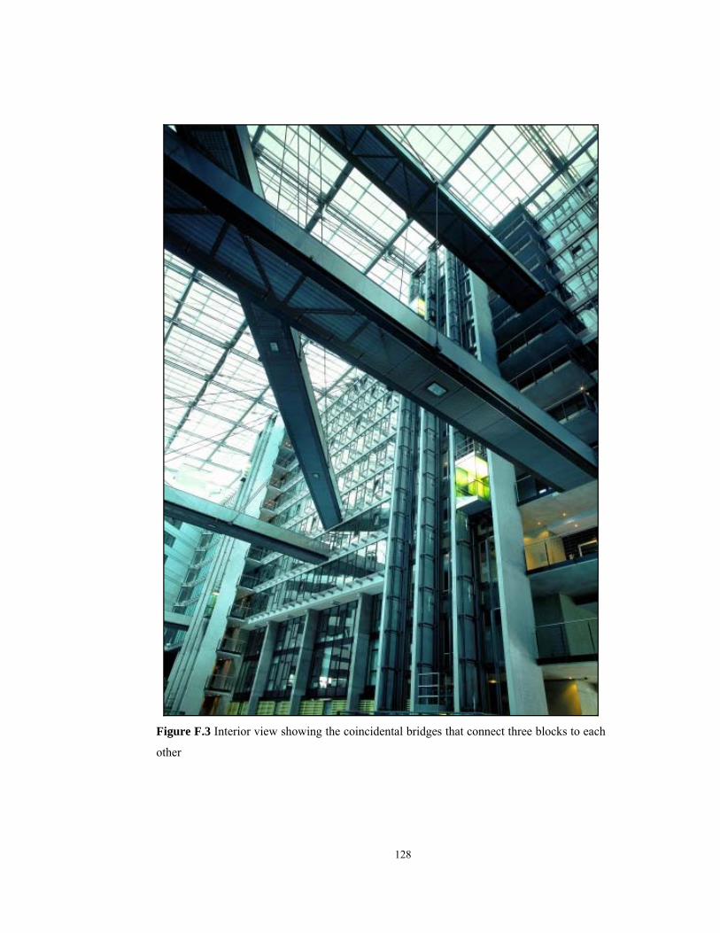
128
Figure F.3 Interior view showing the coincidental bridges that connect three blocks to each
other

129
Figure F.4 The cavity of the double skin façade showing the top vents

130
F
igur
e F.
5 C
onst
ruct
ion
stag
e of
the
doub
le sk
in fa
çade

131
F
igur
e F.
6 To
p vi
ew o
f the
bui
ldin
g lo
okin
g at
the
fron
t blo
ck

132
Fig
ure
F.7
Top
vie
w o
f the
bui
ldin
g lo
okin
g at
the
side
blo
ck

133
F
igur
e F.
8 In
terio
r vie
w o
f the
bui
ldin
g sh
owin
g th
e at
rium
and
gla
ss ro
of

134
APPENDIX G
Airflow simulation results
The offices oriented to the double-skin façade in the summer simulation when
outside temperature was 30°C:
The atrium temperature remained at 25°C
The temperature in the hall remained at 24°C.
The temperatures of the room interior surface were determined by means of
the dynamic building load simulation (TRNSYS) with around 24°C.
The flue of the double façade connected to its back front areas with a
constant temperature of 25°C.
In order to guarantee 2-fold air change in the double façade offices, the
current speed in the canals with 0.5 m/s was purported.
The current speed in the window openings to the atrium was determined
with 0.04 m/s in order to guarantee 2-fold air change also in these offices.
The entrance speed of the air into the lower part of the double façade section
observed by 0.22 m/s. with TRNSYS and also yielded air temperatures in
this area was approximately 38°C (in front of the shading device) and 34°C
(behind the shading device).
The internal heat occurred by occupants and computers was 20 W/ms² for
office areas.
The offices oriented to the double-skin façade in winter simulation when the
outside temperature was about –8°C:
The atrium temperature remained at 15°C.
The interior room surface temperatures were found 20°C with TRNSYS.
The flue of the double façade connected to its back front areas with a
constant temperature of 20 °C.
To guarantee 1-fold air change in the double façade offices, air speed with a

135
0.25 m/s in the canals was purported.
The air speed in the window openings to the atrium was determined with 0.1
m/s in order to guarantee 1-fold air change also in the offices oriented to the
hall.
For the entrance temperatures of the incoming air of the channels into the
atrium bureaus were resulted over 18°C, supposed with 12°C as constant.
The air entered with a temperature of –3°C into the observation zone of the
double façade.
Internal heat by occupants and computer were 20 W/ms² for the office areas.
In order to receive comfortable room temperatures in the double façade and
atrium bureaus, additional heat gains of 320 W in the double façade offices
and 400 W in the atrium offices were purported for 5m² office area.
The atrium in the summer simulation:
The entrance temperature of the earth canal air remained at 26°C with a 2-
fold air change in the atrium.
Glass façade at the ground floor outward was 32°C.
Wall temperature of the third floor was 26°C.
Wall temperatures of fourth floor to the seventh floors were 28°C.
Wall temperatures of eighth and ninth floors were 34°C.
Surface temperature beneath the glass roof was 36°C.
The atrium in the winter simulation when the outside temperature was –5°C:
From the offices an air volume steps over the window openings into the hall
that corresponds in the offices per hour to a 1-fold-air change.
The retirement temperature out of the offices was around 22°C.
Wall temperatures of the atrium to the offices were 15°C.
Outside air infiltration of 50 m3/h was allowed over the glass façade in the
ground floor.
Surface temperature of the ground was determined 7°C as constant by means
of a k -value of 0.45 W/m²K with an underground garage temperature of 5°C.
Surface temperature of the warm shelter glazing of the roof glass is
determined 10°C as constant by means of a k-value of 1.6 W/m²K.
Surface temperature of the deck of the upper-story offices was determined
10°C with a k-value of 0.36 W/m²K and an office temperature of 22°C.

136