energy management system in smart grid ieee
TRANSCRIPT
Energy Resource Management in Smart GridKartheepan Balachandran1, Jan Dimon Bendtsen2, Rasmus Loevenstein Olsen1, Jens Myrup Pedersen1
1Netsec, 2Control, Aalborg University, Frederik Bajers Vej 7A, 9220 Aalborg, Denmark{rlo, kba, jdb, jmp}@es.aau.dk
Denmark
Abstract—Smart grids are characterized by a dynamic na-ture in which distributed energy resources (DER’s) changesinternal states and availability over time. Distributed EnergyResources (DER’s) and the distributed control system will thusbe required to automatically configure itself to this dynamicbehavior. This paper1 addresses communication and controlchallenges to achieve a plug’n’play type of DER management.A use case with Electric Vehicles is considered because of itshigh dynamic behavior in smart grid. In particular, the problemof making correct decisions on which controller out of many,an EV shall be operated by will be addressed. This is not anisolated control problem, but for reliable decisions also requiresto take into account characteristics of the involved networksin combination with the dynamics of the decision informationat the controllers. In the paper we propose a decentralized(de)register/reconfiguration protocol and evaluate its ability tolead to reliable decisions of EV assignments to controllers in ahierarchical multi control system.
Index Terms—Smart Grid, AMI, DER, DER Management,Control, Communication.
I. INTRODUCTION AND BACKGROUND
The next generation of electric power infrastructure is calledthe Smart Grid. The new grid system makes it possible toutilize existing distributed energy resources (DER) and therebyoptimize the demand and response (DR) using Direct LoadControl (DLC) [1]. The DER can be e.g. electric vehicles orheat pumps, which can take load off or shift load in time on thegrid, and thereby contribute to load balancing on the grid andsave the utility companies to pay for neighbor countries to takeoff the load [2][3]. Consumers having different DERs availableare also called prosumer, which are costumers who are ableto consume and produce power and are connected through anAdvanced Metering Infrastructure (AMI) [4]. Being able tolet the utility company use the DERs from their costumers,entitles the costumers to get benefits on their electricity bills.
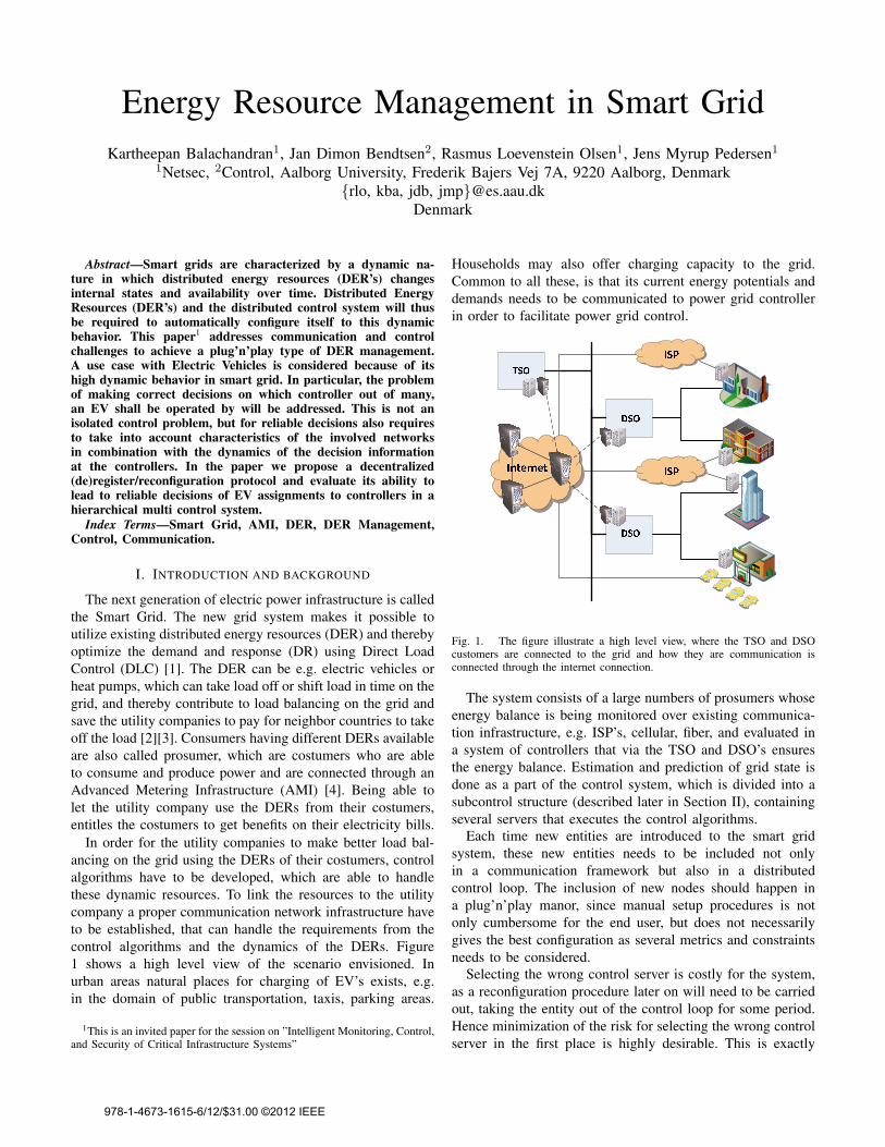
In order for the utility companies to make better load bal-ancing on the grid using the DERs of their costumers, controlalgorithms have to be developed, which are able to handlethese dynamic resources. To link the resources to the utilitycompany a proper communication network infrastructure haveto be established, that can handle the requirements from thecontrol algorithms and the dynamics of the DERs. Figure1 shows a high level view of the scenario envisioned. Inurban areas natural places for charging of EV’s exists, e.g.in the domain of public transportation, taxis, parking areas.
1This is an invited paper for the session on ”Intelligent Monitoring, Control,and Security of Critical Infrastructure Systems”
Households may also offer charging capacity to the grid.Common to all these, is that its current energy potentials anddemands needs to be communicated to power grid controllerin order to facilitate power grid control.
Fig. 1. The figure illustrate a high level view, where the TSO and DSOcustomers are connected to the grid and how they are communication isconnected through the internet connection.
The system consists of a large numbers of prosumers whoseenergy balance is being monitored over existing communica-tion infrastructure, e.g. ISP’s, cellular, fiber, and evaluated ina system of controllers that via the TSO and DSO’s ensuresthe energy balance. Estimation and prediction of grid state isdone as a part of the control system, which is divided into asubcontrol structure (described later in Section II), containingseveral servers that executes the control algorithms.
Each time new entities are introduced to the smart gridsystem, these new entities needs to be included not onlyin a communication framework but also in a distributedcontrol loop. The inclusion of new nodes should happen ina plug’n’play manor, since manual setup procedures is notonly cumbersome for the end user, but does not necessarilygives the best configuration as several metrics and constraintsneeds to be considered.
Selecting the wrong control server is costly for the system,as a reconfiguration procedure later on will need to be carriedout, taking the entity out of the control loop for some period.Hence minimization of the risk for selecting the wrong controlserver in the first place is highly desirable. This is exactly
978-1-4673-1615-6/12/$31.00 ©2012 IEEE
the topic of the paper. The involved subsystems and theirproperties complicates matter of which control loop an energyresource should become a part of when entering a runningsystem, and some of these information (examples shown in thebelow bullet list) are also dynamic which poses a challenge tothe reliability of the control server selection.
∙ Network properties (delay, jitter, packet loss, data rates,congestion levels)
∙ Control properties (information types, control methods,control frequency)
∙ Energy grid properties (line capacity, existing energyflows)
The dynamic (re)entry of controllable energy resources aremost prominent in charging of electric vehicles, however, isalso relevant for households or building upon installation ofsmart grid support mechanisms (although, with a much lowerdynamics than the EV type of scenario). Hence, we will in thispaper focus on the EV scenario type due to the challengingdynamics.
The contribution of this paper is a high level protocoldescription of automatic discovery of the correct controlsubsystem, as well its ability to select the correct control serverby proper adjustment of a single protocol parameter. We donot consider the actual selection algorithm in this paper.
II. CONTROL SYSTEM CONCEPT
A. Control system architecture
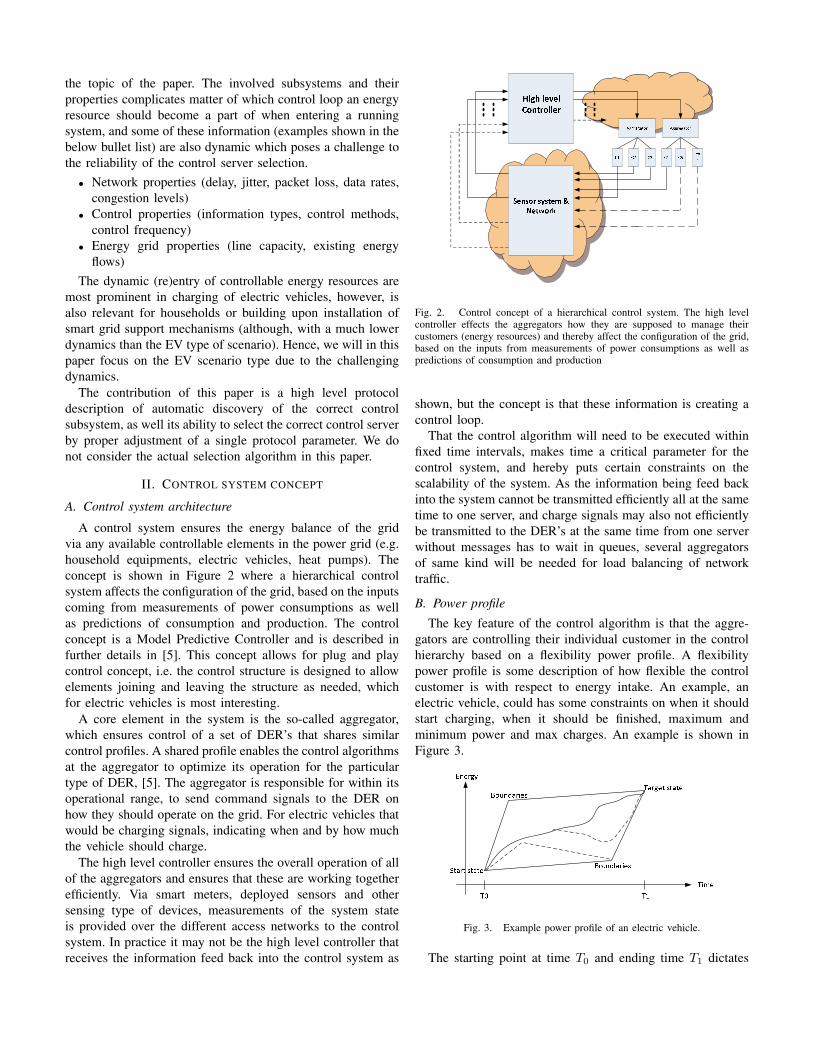
A control system ensures the energy balance of the gridvia any available controllable elements in the power grid (e.g.household equipments, electric vehicles, heat pumps). Theconcept is shown in Figure 2 where a hierarchical controlsystem affects the configuration of the grid, based on the inputscoming from measurements of power consumptions as wellas predictions of consumption and production. The controlconcept is a Model Predictive Controller and is described infurther details in [5]. This concept allows for plug and playcontrol concept, i.e. the control structure is designed to allowelements joining and leaving the structure as needed, whichfor electric vehicles is most interesting.
A core element in the system is the so-called aggregator,which ensures control of a set of DER’s that shares similarcontrol profiles. A shared profile enables the control algorithmsat the aggregator to optimize its operation for the particulartype of DER, [5]. The aggregator is responsible for within itsoperational range, to send command signals to the DER onhow they should operate on the grid. For electric vehicles thatwould be charging signals, indicating when and by how muchthe vehicle should charge.
The high level controller ensures the overall operation of allof the aggregators and ensures that these are working togetherefficiently. Via smart meters, deployed sensors and othersensing type of devices, measurements of the system stateis provided over the different access networks to the controlsystem. In practice it may not be the high level controller thatreceives the information feed back into the control system as
Fig. 2. Control concept of a hierarchical control system. The high levelcontroller effects the aggregators how they are supposed to manage theircustomers (energy resources) and thereby affect the configuration of the grid,based on the inputs from measurements of power consumptions as well aspredictions of consumption and production
shown, but the concept is that these information is creating acontrol loop.
That the control algorithm will need to be executed withinfixed time intervals, makes time a critical parameter for thecontrol system, and hereby puts certain constraints on thescalability of the system. As the information being feed backinto the system cannot be transmitted efficiently all at the sametime to one server, and charge signals may also not efficientlybe transmitted to the DER’s at the same time from one serverwithout messages has to wait in queues, several aggregatorsof same kind will be needed for load balancing of networktraffic.
B. Power profile
The key feature of the control algorithm is that the aggre-gators are controlling their individual customer in the controlhierarchy based on a flexibility power profile. A flexibilitypower profile is some description of how flexible the controlcustomer is with respect to energy intake. An example, anelectric vehicle, could has some constraints on when it shouldstart charging, when it should be finished, maximum andminimum power and max charges. An example is shown inFigure 3.
Fig. 3. Example power profile of an electric vehicle.
The starting point at time 𝑇0 and ending time 𝑇1 dictates
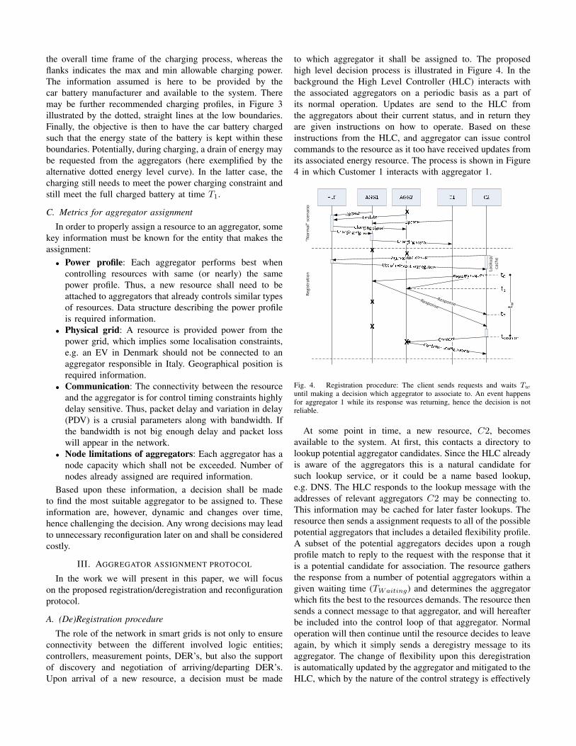
the overall time frame of the charging process, whereas theflanks indicates the max and min allowable charging power.The information assumed is here to be provided by thecar battery manufacturer and available to the system. Theremay be further recommended charging profiles, in Figure 3illustrated by the dotted, straight lines at the low boundaries.Finally, the objective is then to have the car battery chargedsuch that the energy state of the battery is kept within theseboundaries. Potentially, during charging, a drain of energy maybe requested from the aggregators (here exemplified by thealternative dotted energy level curve). In the latter case, thecharging still needs to meet the power charging constraint andstill meet the full charged battery at time 𝑇1.
C. Metrics for aggregator assignment
In order to properly assign a resource to an aggregator, somekey information must be known for the entity that makes theassignment:
∙ Power profile: Each aggregator performs best whencontrolling resources with same (or nearly) the samepower profile. Thus, a new resource shall need to beattached to aggregators that already controls similar typesof resources. Data structure describing the power profileis required information.
∙ Physical grid: A resource is provided power from thepower grid, which implies some localisation constraints,e.g. an EV in Denmark should not be connected to anaggregator responsible in Italy. Geographical position isrequired information.
∙ Communication: The connectivity between the resourceand the aggregator is for control timing constraints highlydelay sensitive. Thus, packet delay and variation in delay(PDV) is a crusial parameters along with bandwidth. Ifthe bandwidth is not big enough delay and packet losswill appear in the network.
∙ Node limitations of aggregators: Each aggregator has anode capacity which shall not be exceeded. Number ofnodes already assigned are required information.
Based upon these information, a decision shall be madeto find the most suitable aggregator to be assigned to. Theseinformation are, however, dynamic and changes over time,hence challenging the decision. Any wrong decisions may leadto unnecessary reconfiguration later on and shall be consideredcostly.
III. AGGREGATOR ASSIGNMENT PROTOCOL
In the work we will present in this paper, we will focuson the proposed registration/deregistration and reconfigurationprotocol.
A. (De)Registration procedure
The role of the network in smart grids is not only to ensureconnectivity between the different involved logic entities;controllers, measurement points, DER’s, but also the supportof discovery and negotiation of arriving/departing DER’s.Upon arrival of a new resource, a decision must be made
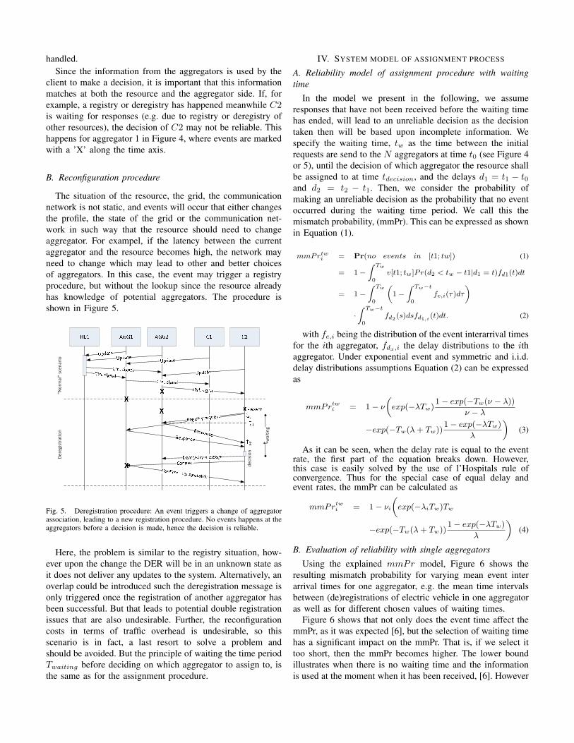
to which aggregator it shall be assigned to. The proposedhigh level decision process is illustrated in Figure 4. In thebackground the High Level Controller (HLC) interacts withthe associated aggregators on a periodic basis as a part ofits normal operation. Updates are send to the HLC fromthe aggregators about their current status, and in return theyare given instructions on how to operate. Based on theseinstructions from the HLC, and aggregator can issue controlcommands to the resource as it too have received updates fromits associated energy resource. The process is shown in Figure4 in which Customer 1 interacts with aggregator 1.
Response”N
orm
al”
scen
ario
Re
gist
ratio
n
Response
Look
up/
cach
e
t w
Fig. 4. Registration procedure: The client sends requests and waits 𝑇𝑤
until making a decision which aggegrator to associate to. An event happensfor aggregator 1 while its response was returning, hence the decision is notreliable.
At some point in time, a new resource, 𝐶2, becomesavailable to the system. At first, this contacts a directory tolookup potential aggregator candidates. Since the HLC alreadyis aware of the aggregators this is a natural candidate forsuch lookup service, or it could be a name based lookup,e.g. DNS. The HLC responds to the lookup message with theaddresses of relevant aggregators 𝐶2 may be connecting to.This information may be cached for later faster lookups. Theresource then sends a assignment requests to all of the possiblepotential aggregators that includes a detailed flexibility profile.A subset of the potential aggregators decides upon a roughprofile match to reply to the request with the response that itis a potential candidate for association. The resource gathersthe response from a number of potential aggregators within agiven waiting time (𝑇𝑊𝑎𝑖𝑡𝑖𝑛𝑔) and determines the aggregatorwhich fits the best to the resources demands. The resource thensends a connect message to that aggregator, and will hereafterbe included into the control loop of that aggregator. Normaloperation will then continue until the resource decides to leaveagain, by which it simply sends a deregistry message to itsaggregator. The change of flexibility upon this deregistrationis automatically updated by the aggregator and mitigated to theHLC, which by the nature of the control strategy is effectively
handled.Since the information from the aggregators is used by the
client to make a decision, it is important that this informationmatches at both the resource and the aggregator side. If, forexample, a registry or deregistry has happened meanwhile 𝐶2is waiting for responses (e.g. due to registry or deregistry ofother resources), the decision of 𝐶2 may not be reliable. Thishappens for aggregator 1 in Figure 4, where events are markedwith a ’X’ along the time axis.
B. Reconfiguration procedure
The situation of the resource, the grid, the communicationnetwork is not static, and events will occur that either changesthe profile, the state of the grid or the communication net-work in such way that the resource should need to changeaggregator. For exampel, if the latency between the currentaggregator and the resource becomes high, the network mayneed to change which may lead to other and better choicesof aggregators. In this case, the event may trigger a registryprocedure, but without the lookup since the resource alreadyhas knowledge of potential aggregators. The procedure isshown in Figure 5.
”Nor
mal
” sc
enar
io
Dere
gist
ratio
n
deci
sion
t wai
ting
Fig. 5. Deregistration procedure: An event triggers a change of aggregatorassociation, leading to a new registration procedure. No events happens at theaggregators before a decision is made, hence the decision is reliable.
Here, the problem is similar to the registry situation, how-ever upon the change the DER will be in an unknown state asit does not deliver any updates to the system. Alternatively, anoverlap could be introduced such the deregistration message isonly triggered once the registration of another aggregator hasbeen successful. But that leads to potential double registrationissues that are also undesirable. Further, the reconfigurationcosts in terms of traffic overhead is undesirable, so thisscenario is in fact, a last resort to solve a problem andshould be avoided. But the principle of waiting the time period𝑇𝑤𝑎𝑖𝑡𝑖𝑛𝑔 before deciding on which aggregator to assign to, isthe same as for the assignment procedure.
IV. SYSTEM MODEL OF ASSIGNMENT PROCESS
A. Reliability model of assignment procedure with waitingtime
In the model we present in the following, we assumeresponses that have not been received before the waiting timehas ended, will lead to an unreliable decision as the decisiontaken then will be based upon incomplete information. Wespecify the waiting time, 𝑡𝑤 as the time between the initialrequests are send to the 𝑁 aggregators at time 𝑡0 (see Figure 4or 5), until the decision of which aggregator the resource shallbe assigned to at time 𝑡𝑑𝑒𝑐𝑖𝑠𝑖𝑜𝑛, and the delays 𝑑1 = 𝑡1 − 𝑡0and 𝑑2 = 𝑡2 − 𝑡1. Then, we consider the probability ofmaking an unreliable decision as the probability that no eventoccurred during the waiting time period. We call this themismatch probability, (mmPr). This can be expressed as shownin Equation (1).
𝑚𝑚𝑃𝑟𝑡𝑤𝑖 = Pr(𝑛𝑜 𝑒𝑣𝑒𝑛𝑡𝑠 𝑖𝑛 [𝑡1; 𝑡𝑤]) (1)
= 1−∫ 𝑇𝑤
0𝑣[𝑡1; 𝑡𝑤]𝑃𝑟(𝑑2 < 𝑡𝑤 − 𝑡1∣𝑑1 = 𝑡)𝑓𝑑1(𝑡)𝑑𝑡
= 1−∫ 𝑇𝑤
0
(1−
∫ 𝑇𝑤−𝑡
0𝑓𝑒,𝑖(𝜏)𝑑𝜏
)
⋅∫ 𝑇𝑤−𝑡
0𝑓𝑑2 (𝑠)𝑑𝑠𝑓𝑑1,𝑖 (𝑡)𝑑𝑡. (2)
with 𝑓𝑒,𝑖 being the distribution of the event interarrival timesfor the 𝑖th aggregator, 𝑓𝑑𝑥,𝑖 the delay distributions to the 𝑖thaggregator. Under exponential event and symmetric and i.i.d.delay distributions assumptions Equation (2) can be expressedas
𝑚𝑚𝑃𝑟𝑡𝑤𝑖 = 1− 𝜈
(𝑒𝑥𝑝(−𝜆𝑇𝑤)
1− 𝑒𝑥𝑝(−𝑇𝑤(𝜈 − 𝜆))
𝜈 − 𝜆
−𝑒𝑥𝑝(−𝑇𝑤(𝜆+ 𝑇𝑤))1− 𝑒𝑥𝑝(−𝜆𝑇𝑤)
𝜆
)(3)
As it can be seen, when the delay rate is equal to the eventrate, the first part of the equation breaks down. However,this case is easily solved by the use of l’Hospitals rule ofconvergence. Thus for the special case of equal delay andevent rates, the mmPr can be calculated as
𝑚𝑚𝑃𝑟𝑡𝑤𝑖 = 1− 𝜈𝑖
(𝑒𝑥𝑝(−𝜆𝑖𝑇𝑤)𝑇𝑤
−𝑒𝑥𝑝(−𝑇𝑤(𝜆+ 𝑇𝑤))1− 𝑒𝑥𝑝(−𝜆𝑇𝑤)
𝜆
)(4)
B. Evaluation of reliability with single aggregators
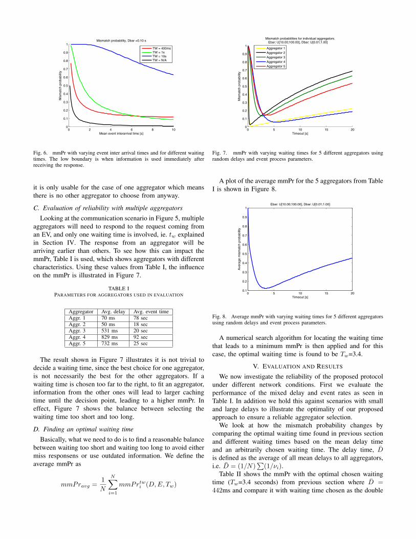
Using the explained 𝑚𝑚𝑃𝑟 model, Figure 6 shows theresulting mismatch probability for varying mean event interarrival times for one aggregator, e.g. the mean time intervalsbetween (de)registrations of electric vehicle in one aggregatoras well as for different chosen values of waiting times.
Figure 6 shows that not only does the event time affect themmPr, as it was expected [6], but the selection of waiting timehas a significant impact on the mmPr. That is, if we select ittoo short, then the mmPr becomes higher. The lower boundillustrates when there is no waiting time and the informationis used at the moment when it has been received, [6]. However
0 2 4 6 8 100
0.1
0.2
0.3
0.4
0.5
0.6
0.7
0.8
0.9
1
Mean event interarrival time [s]
Mis
mat
ch p
roba
bilit
y
Mismatch probability, Dbar =0.10 s
TW = 400msTW = 1sTW = 10sTW = N/A
Fig. 6. mmPr with varying event inter arrival times and for different waitingtimes. The low boundary is when information is used immediately afterreceiving the response.
it is only usable for the case of one aggregator which meansthere is no other aggregator to choose from anyway.
C. Evaluation of reliability with multiple aggregators
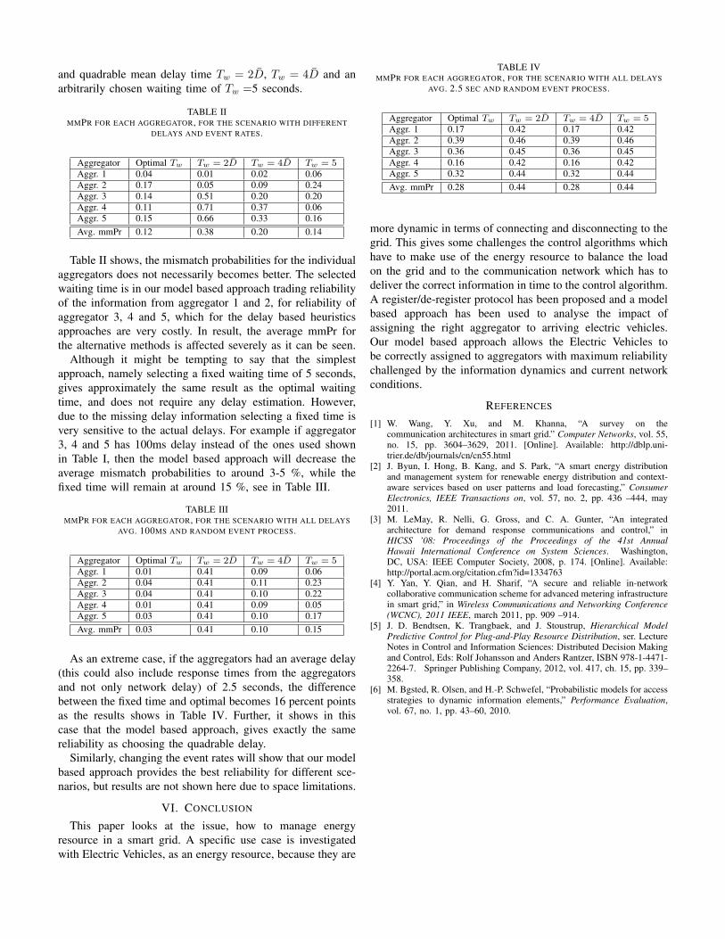
Looking at the communication scenario in Figure 5, multipleaggregators will need to respond to the request coming froman EV, and only one waiting time is involved, ie. 𝑡𝑤 explainedin Section IV. The response from an aggregator will bearriving earlier than others. To see how this can impact themmPr, Table I is used, which shows aggregators with differentcharacteristics. Using these values from Table I, the influenceon the mmPr is illustrated in Figure 7.
TABLE IPARAMETERS FOR AGGREGATORS USED IN EVALUATION
Aggregator Avg. delay Avg. event timeAggr. 1 70 ms 78 secAggr. 2 50 ms 18 secAggr. 3 531 ms 20 secAggr. 4 829 ms 92 secAggr. 5 732 ms 25 sec
The result shown in Figure 7 illustrates it is not trivial todecide a waiting time, since the best choice for one aggregator,is not necessarily the best for the other aggregators. If awaiting time is chosen too far to the right, to fit an aggregator,information from the other ones will lead to larger cachingtime until the decision point, leading to a higher mmPr. Ineffect, Figure 7 shows the balance between selecting thewaiting time too short and too long.
D. Finding an optimal waiting time
Basically, what we need to do is to find a reasonable balancebetween waiting too short and waiting too long to avoid eithermiss responsens or use outdated information. We define theaverage mmPr as
𝑚𝑚𝑃𝑟𝑎𝑣𝑔 =1
𝑁
𝑁∑
𝑖=1
𝑚𝑚𝑃𝑟𝑡𝑤𝑖 (𝐷,𝐸, 𝑇𝑤)
0 5 10 15 200
0.1
0.2
0.3
0.4
0.5
0.6
0.7
0.8
0.9
1
Timeout [s]
Mis
mat
ch p
roba
bilit
y
Mismatch probabilities for individual aggregators.Ebar: U[10.00;100.00], Dbar: U[0.01;1.00]
Aggregator 1Aggregator 2Aggregator 3Aggregator 4Aggregator 5
Fig. 7. mmPr with varying waiting times for 5 different aggregators usingrandom delays and event process parameters.
A plot of the average mmPr for the 5 aggregators from TableI is shown in Figure 8.
0 5 10 15 200.1
0.2
0.3
0.4
0.5
0.6
0.7
0.8
0.9
1
Timeout [s]
Ave
rage
mis
mat
ch p
roba
bilit
y
Ebar: U[10.00;100.00], Dbar: U[0.01;1.00]
Fig. 8. Average mmPr with varying waiting times for 5 different aggregatorsusing random delays and event process parameters.
A numerical search algorithm for locating the waiting timethat leads to a minimum mmPr is then applied and for thiscase, the optimal waiting time is found to be 𝑇𝑤=3.4.
V. EVALUATION AND RESULTS
We now investigate the reliability of the proposed protocolunder different network conditions. First we evaluate theperformance of the mixed delay and event rates as seen inTable I. In addition we hold this against scenarios with smalland large delays to illustrate the optimality of our proposedapproach to ensure a reliable aggregator selection.
We look at how the mismatch probability changes bycomparing the optimal waiting time found in previous sectionand different waiting times based on the mean delay timeand an arbitrarily chosen waiting time. The delay time, �̄�is defined as the average of all mean delays to all aggregators,i.e. �̄� = (1/𝑁)
∑(1/𝜈𝑖).
Table II shows the mmPr with the optimal chosen waitingtime (𝑇𝑤=3.4 seconds) from previous section where �̄� =442ms and compare it with waiting time chosen as the double
and quadrable mean delay time 𝑇𝑤 = 2�̄�, 𝑇𝑤 = 4�̄� and anarbitrarily chosen waiting time of 𝑇𝑤 =5 seconds.
TABLE IIMMPR FOR EACH AGGREGATOR, FOR THE SCENARIO WITH DIFFERENT
DELAYS AND EVENT RATES.
Aggregator Optimal 𝑇𝑤 𝑇𝑤 = 2�̄� 𝑇𝑤 = 4�̄� 𝑇𝑤 = 5Aggr. 1 0.04 0.01 0.02 0.06Aggr. 2 0.17 0.05 0.09 0.24Aggr. 3 0.14 0.51 0.20 0.20Aggr. 4 0.11 0.71 0.37 0.06Aggr. 5 0.15 0.66 0.33 0.16
Avg. mmPr 0.12 0.38 0.20 0.14
Table II shows, the mismatch probabilities for the individualaggregators does not necessarily becomes better. The selectedwaiting time is in our model based approach trading reliabilityof the information from aggregator 1 and 2, for reliability ofaggregator 3, 4 and 5, which for the delay based heuristicsapproaches are very costly. In result, the average mmPr forthe alternative methods is affected severely as it can be seen.
Although it might be tempting to say that the simplestapproach, namely selecting a fixed waiting time of 5 seconds,gives approximately the same result as the optimal waitingtime, and does not require any delay estimation. However,due to the missing delay information selecting a fixed time isvery sensitive to the actual delays. For example if aggregator3, 4 and 5 has 100ms delay instead of the ones used shownin Table I, then the model based approach will decrease theaverage mismatch probabilities to around 3-5 %, while thefixed time will remain at around 15 %, see in Table III.
TABLE IIIMMPR FOR EACH AGGREGATOR, FOR THE SCENARIO WITH ALL DELAYS
AVG. 100MS AND RANDOM EVENT PROCESS.
Aggregator Optimal 𝑇𝑤 𝑇𝑤 = 2�̄� 𝑇𝑤 = 4�̄� 𝑇𝑤 = 5Aggr. 1 0.01 0.41 0.09 0.06Aggr. 2 0.04 0.41 0.11 0.23Aggr. 3 0.04 0.41 0.10 0.22Aggr. 4 0.01 0.41 0.09 0.05Aggr. 5 0.03 0.41 0.10 0.17
Avg. mmPr 0.03 0.41 0.10 0.15
As an extreme case, if the aggregators had an average delay(this could also include response times from the aggregatorsand not only network delay) of 2.5 seconds, the differencebetween the fixed time and optimal becomes 16 percent pointsas the results shows in Table IV. Further, it shows in thiscase that the model based approach, gives exactly the samereliability as choosing the quadrable delay.
Similarly, changing the event rates will show that our modelbased approach provides the best reliability for different sce-narios, but results are not shown here due to space limitations.
VI. CONCLUSION
This paper looks at the issue, how to manage energyresource in a smart grid. A specific use case is investigatedwith Electric Vehicles, as an energy resource, because they are
TABLE IVMMPR FOR EACH AGGREGATOR, FOR THE SCENARIO WITH ALL DELAYS
AVG. 2.5 SEC AND RANDOM EVENT PROCESS.
Aggregator Optimal 𝑇𝑤 𝑇𝑤 = 2�̄� 𝑇𝑤 = 4�̄� 𝑇𝑤 = 5Aggr. 1 0.17 0.42 0.17 0.42Aggr. 2 0.39 0.46 0.39 0.46Aggr. 3 0.36 0.45 0.36 0.45Aggr. 4 0.16 0.42 0.16 0.42Aggr. 5 0.32 0.44 0.32 0.44
Avg. mmPr 0.28 0.44 0.28 0.44
more dynamic in terms of connecting and disconnecting to thegrid. This gives some challenges the control algorithms whichhave to make use of the energy resource to balance the loadon the grid and to the communication network which has todeliver the correct information in time to the control algorithm.A register/de-register protocol has been proposed and a modelbased approach has been used to analyse the impact ofassigning the right aggregator to arriving electric vehicles.Our model based approach allows the Electric Vehicles tobe correctly assigned to aggregators with maximum reliabilitychallenged by the information dynamics and current networkconditions.
REFERENCES
[1] W. Wang, Y. Xu, and M. Khanna, “A survey on thecommunication architectures in smart grid.” Computer Networks, vol. 55,no. 15, pp. 3604–3629, 2011. [Online]. Available: http://dblp.uni-trier.de/db/journals/cn/cn55.html
[2] J. Byun, I. Hong, B. Kang, and S. Park, “A smart energy distributionand management system for renewable energy distribution and context-aware services based on user patterns and load forecasting,” ConsumerElectronics, IEEE Transactions on, vol. 57, no. 2, pp. 436 –444, may2011.
[3] M. LeMay, R. Nelli, G. Gross, and C. A. Gunter, “An integratedarchitecture for demand response communications and control,” inHICSS ’08: Proceedings of the Proceedings of the 41st AnnualHawaii International Conference on System Sciences. Washington,DC, USA: IEEE Computer Society, 2008, p. 174. [Online]. Available:http://portal.acm.org/citation.cfm?id=1334763
[4] Y. Yan, Y. Qian, and H. Sharif, “A secure and reliable in-networkcollaborative communication scheme for advanced metering infrastructurein smart grid,” in Wireless Communications and Networking Conference(WCNC), 2011 IEEE, march 2011, pp. 909 –914.
[5] J. D. Bendtsen, K. Trangbaek, and J. Stoustrup, Hierarchical ModelPredictive Control for Plug-and-Play Resource Distribution, ser. LectureNotes in Control and Information Sciences: Distributed Decision Makingand Control, Eds: Rolf Johansson and Anders Rantzer, ISBN 978-1-4471-2264-7. Springer Publishing Company, 2012, vol. 417, ch. 15, pp. 339–358.
[6] M. Bgsted, R. Olsen, and H.-P. Schwefel, “Probabilistic models for accessstrategies to dynamic information elements,” Performance Evaluation,vol. 67, no. 1, pp. 43–60, 2010.