energy loss in commercial insulating materials when subjected to high potential stress
TRANSCRIPT

A paper presented at the 19th Annual Convention ofthe American Institute of Electrical Engineers,Great Barrington, Mass., /une 20th. 1902
ENERGY LOSS IN COMMERCIAL INSULATING MATE-RIALS WHEN SUBJECTED TO HIGH POTENTIAL
STRESS.
BY CHARLES EDWARD SKINNER.
Those who have had occasion to test the dielectric strengthof insulating materials by means of alternating e.m.f. are familiarwith the fact that heat is always developed in these materialsduring such test. This is especially noticeable when the testis long continued at a point approximating the breaking downstrength of the material. When the amount of material in-volved is large, ordinary indicating instruments will show atonce that there is an actual loss of energy. The fact that energyloss exists under such conditions has been known for more than adecade, having been first shown by the experiments of Siemens,and later investigated by others. Published investigations on thissubject relate almost entirely to the energy loss in the insulatingmaterial, or dielectric of condensers. The law of variation ofloss, due to variation of voltage, was first announced bv Iir. C. P.Steinmetz' early in 1892. At that time Mr. Steinmetz gavethis loss the name of " dielectric hysteresis " because of itsapparent similarity to the phenomenon known as hvsteresis iniron and steel. Since that time other writers, notably Arno2,Hess' and Borel4, have made experiments from which they con-clude that this energy loss is not in the nature of a dielectrichysteresis, and various theories have been advanced concerningits nature and cause.)
1. Electrical Engineer, March 16, 1892.2. Electricia%n (London), March 3, 1893, and June 23, 1893.3. 7ournal de Physique, April, 1893.4. Comp/cs Rendus, May 23, 1893.5. Ti-te Electrician (London), Noveimlber 1, 1895.
1047

1048 SKINNER: INSULATING MATERIAL. [Jtne 20
It is not the object of this paper to discuss the theories of theorigin or cause, but rather the effects of this loss, and in tlheabsence of a name which can be accepted as descriptive andfinal, it will be spoken of as " energy loss " or " loss."
It is the intention to describe some of the metlhods employedand to give some of the characteristic results obtained from testsmade on various materials used in commercial manufacture,and also on the insulation of finished apparatus. These testshave been made from time to time during the last five or sixyears, and have covered a great variety of materials. The majorpart of the tests, however, h-ave been made on materials of afibrous nature, such as paper and cloth, both in the treated anduntreated state, and the discussion will be largely confined tothis class. By treated material is meant a paper or cloth coatedwith some sort of insulating varnish. The samples used weretaken from stock, and standard manufacturing methods werefollowed as far as possible in preparing them for the tests.
The action of ordinary commercial insulatinig material underhiglh potential stress is usually so erratic, owing to surroundinginfluences, such as temperature, moisture, ventilation, etc., thata considerable number of observations are usually necessaryin order to reach any satisfactory conclusions. For this reasonthe specific tests which are given in this paper are intended toshow characteristic and not quantitative results, and are, there-fore, not to be taken for other materials or even for other sam-ples of the same material. Individual tests are of little valueexcept as they fit in a series, or, unless the conditions surround-ing them are known to the minutest detail.
For these tests, alternating current at the standard frequenciesof 25, 60 and 133 cycles was used, the e.m.f. varying from a fewthousand volts to upward of 100,000 volts. The majority ofthe tests referred to were made on material subjected to a poten-tial stress muchi in excess of that ordinarily used in actual prac-tice, this being done both on account of the fact that the variousphenomiena are muclh mnore marked at the higher stresses, andalso because a much smaller amount of material could be usedfor each individual test. The results, while being true forpotential stresses, are of little commercial importance inordinary low potential apparatus. They become, however,of the greatest importance in very high potential working, andespecially so with condensers for use on high potential circuits.The results also have a direct bearing on the question of lolng-

1902.] SKINNER; INSULATING MATERIAL. 1049
continued tests of the dielectric strength of finished apparatusat very high voltages. The various phenomena noted are sointer-dependent that it is difficult to describe onie without refer-ring to others, and at times it will be necessary to anticipateresults which are to be described later.
VARIATION OF TEMPERATURE DUE TO VARIATION OF STRESS.When an alternating high potential stress is applied to insulat-
ing material, the temperature of the whole mass rises, but owingto the fact that all insulating materials are poor conductors ofheat, the temperature of the inner portions rises above that of theouter portions,which have a better opportunity of dissipating theirheat. A considerable number of tests have been made to deter-mine the rise of temperature in the interior of a mass of insulat-ing material under different conditions of stress. Usually thesetests did not include the measurement of the amount of energyloss, as the results sought were the ventilation required underworking conditions and the dielectric strength at various tem-peratures. The tests were usually made by placing the materialbetween metal plates, which were connected to the terminalsof a high potential transformer. The plates employed for this pur-pose should always have well-rounded edges to prevent theunduestress which occurs at sharp corners. The size of the platesvaried in different tests, but the most satisfactory results wereobtained with plates approximately 9" in diameter, whose edgeswere rounded to a radius of about 12".
Various methods of measuring the temperature were tried,but only one gave entire satisfaction. A mercury thermometerinserted in the material gave trouble, especially at the higherpotentials, as the mercury was vaporized by the static dischargesin the thermometer tube. A small coil of very fine copper wirewas placed in the material and the temperature determined byits increase of resistance. In long-continued tests this methodwas found unsatisfactory, on account of the rapid oxidation ofthe copper in the presence of the ozone always generated bysuch tests. The most satisfactory temperature readings were
obtained by placing at the point where the temperature was tobe measured, a copper-lead thermo-junction connected to a
sensitive galvanometer. The outer ends of the couple were keptat 0° C. by being placed in ice water. By properly insulatingthe galvanometer, it was found entirely feasible to take readingswith a potential stress of 30,000 volts or more across a 1" layer
1050 SKiNNER' INSULATING MATERIAL. [June 20
of material, with this junction at the center. In some tests anumber of junctions were placed at different points in thematerial, in order to map out the temperature of the variousparts.
In a number of tests the material was arranged as above andthen placed in a box in which was located an electric heater, afan motor being used to circulate the air over the heater andthrough tlhe box, so that anv desired initial temperature couldl)e secured and with care the surrounding temperature regulatedthroughout the test. In some instances insulation resistancewas measured at intervals, the high potential wires being tem-porarily disconnected for this purpose. Usually the insulationresistance was so high as to be very difficult of exact measure-ment with the apparatus at lhand.The test samples used were built up to a thickness of F to '
or more, and tests were made at different voltages up to theultimate dielectric strength of the material. For most of thetests, current was obtained from a dynamo giving very approxi-mately a sine wave of e.n.f. The results of this series of testsmay be given as follows:
(1) With moderate stress the temperature of the materialrises rapidlv at first, then more slowly, then becomes constant.The actual rise in the temperature for a given voltage dependson the facility with which the material can dissipate its heatand on the temperature of the surrounding medium.
(2) As the stress is increased, a point is finallv reached wherethe heat is developed at a greater rate than it can be carriedawav, and temperature then rises until the material chars andbreak-down results.
(3) When material is not thoroughly dried, the temperaturerises mnuch more rapidly than in well-dried stock. The increasedtemperature cannot be accounted for by the increased J2 R lossdue to lower insulation resistance. The heat generated tendst-o dry out the material and the temperature may fall as the dry-..qg proceeds.
(4) With a considerable area of material under test, the tem-perature of small portions frequently rises above that of the sur-rounding material to such an extent that on examination theseportions are found much discolored, while the surrounding por-tions remain unchanged. This effect is especially noticeablewith treated material not perfectly cured. The final break-down in such cases is invariably found in one of the heated areas.

1902.] .KIlNNER- INSULATING iA TELRIAL. 1051
(5) The final break-down in fibrous mnaterials usually resultsfrom the burning of the material and not from mechanicalrupture. When the e.m.f. applied is far above the dielectricstrength of the material, the break-down may be due to a me-chanical rupture. If, however, the e.m.f. is sufficiently low, sothat an appreciable time elapses before break-down occurs, thebreak-down is probably due to burning caused by the heatgenerated in the material. There may be some attendant chemi-cal action, but this is thought to be a result and not a cause ofthe excessive heat. The lower the e.m.f. applied, the longer thetime required to produce break-down under a given set of con-ditions.
(6) It follows from (5) that if the temperature is kept low,either by providing good ventilation or by artificial cooling, thestress required to cause break-down in a time test will be muchgreater than if the material is not so cooled.
(7) The actual temperature measured in most fibrous ma-terials before break-down occurred was usually 175° C. or more.In no case did a break-dowTn occur directly at the point wheretemperature measurements were being made, and the tempera-ture at the breaking down point was probably higher than mea-sured, especially as the rise in temperature seemed to be veryrapid at the point of break-down just before this occurred.
(8) With a given stress, the initial and surrounding tempera-ture has much to do with the rise. This is due to the fact thatthe loss in the material increases rapidly withi the temperature.For example, if the material and surrounding air are at 200 C.and the stress applied is 20,000 volts, the rise in temperaturewill not be nearly so great as if the initial and surrounding tem-perature is at 80° C. Tests have shown that break-down fre-quently results under the latter conditions from a stress thatwould not injure the material under the former conditions.
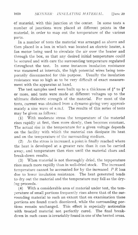
Fig. 1 gives some of the characteristic curves of rise in tem-perature in insulating material when subjected to high potentialstress. Curves A, B and c were taken on a sample of untreatedmaterial which was quite porous and capable of absorbingmoisture from the air. In this test the material was well-ven-tilated, so that any moisture could be quickly dissipated. Thetemperatures given are those actually measured, but probablydo not represent the highest point reached in the material.Curve A shows the effect of moisture. The temperature rose veryrapidly, reaching a maximum, then fell, and at last became
1052 SKINNER: INSUIATING MATERIAL. [june 20
stationary. Curve B shows the effect on the same material aftervery thorough drying. Curve c slhows the increased tempera-ture due to a slight increase in the stress.
Curve D at the upper right hand corner of the figure, shows the
I ~~~~~~~riakdownx9D ~~~i130
__f~~~~~~~~-- r0 / -
80~~~~~~~~~~~0
t;/ \ ~~~~~~~~~~~Ti:ieainutes i
40 C_156 0Vol_ts-TS
4-
0 1"O 20 30~hO 2010
FIG. l.-Showing Increase of Temperature in Insulating Material due toS_tress.
rise in temperature in treated material when poorly vent;ilated,and the test continued until break-downl resulted. Break-dow\nin this particular test occurred at a point about 4/' from thethermo-juniction when the nmeasured te-mperature reached 1350

1902.] SKINNER: INSULATING MIA TERIAL. 1053
C. It is probable that the temperature measured was consider-ably lower than that reached at the point of break-down. Thetemperature of the surrounding air in this test was kept at 80°C.This curve shows the tendency of the temperature to becomeconstant, but at a point slightly over 1000 C. the loss becomes sogreat that the heat cannot be dissipated as fast as generated,hence the change in direction of the curve and final break-down.In numerous tests the material was found to be badly charred:on the interior, without break-down having resulted. Thecurves shown are characteristic, and are of the same form asmany others that have been taken.
VARIATION OF Loss DUE TO VARIATION OF TEMPERATURE.
The measurement of the energy loss due to high potentialstress in a reasonably small sample of insulating material, pre-sents a rather unusual problem. The voltage is high, the currentsmall and the power factor very low. In many of tlhe tests re-ferred to in this paper, it was necessary to measure with somedegree of accuracy, losses of less than 100 watts at an e.m.f. of20,000 to 40,000 volts,at various frequencies, with a power factorless than 0.1. The commercial instruments on the market aretotally unsuited for this work.Many of the measurements to determine the points under dis-
cussion were made by means of a calorimeter. This calorimeterconsisted of a tank filled with mineral oil, in which the samplewas placed. Calibratlon was effected by passing direct currentthrough a resistance coil immersed in the oil and noting the risein temperature of the oil, due to various amounts of energyabsorbed. The rate of cooling from various temperatures wasalso carefully taken and was made use of in deducing many ofthe results. Great care was exercised to secure uniform tem-perature throughout the body of the oil by mechanical stirring,and the calorimeter was carefully shielded from drafts to pre-vent variation in the rate of cooling.The material for these tests was usually built up in the form
of a small condenser, with ventilating spaces between the plates,so that the temperature could be kept as nearly uniform as pos-sible throughout the mass of the material. In the determina-tions of the variation of loss due to variation of temperature bythe calorimeter method, the whole body of oil and insulationwas brought up to some constant temperature, then the highpotential stress applied. The rate of heating or cooling, as the

1054 SKINNER: INSULATING MATERIAL [Julne 20
case might be, due to the loss in the insulation being greater orless than required to hold the calorimeter at this constant tem-perature, was then noted and the actual loss was derived by theuse of the calibration curves of the calorimeter. These testsrequired great care, were very tedious and many correctionswere required in deducing the results.
After a considerable amount of work had been done by thecalorimeter method, a static wattmeter' was constructed andthe work continued with this instrument. With this wattmeter,which was admirably suited to this work, a complete curve couldbe taken in the time required to determine a single point by thecalorimeter method. It was a source of considerable satisfac-tion to find that the calorimeter and wattmeter methods checkedeach other with a very fair degree of accuracy, especially con-sidering the nature of the materials on which the measurements,were made.
In Fig. 2 are given curves which are characteristic in form forthe increase in loss due to temperature. These particular curves,were taken by the wattmeter method on a sample of materialwhich had been used for some months for other tests and was.known to be in the very best condition as regards moisture, etc.This general form of curve has been found to hold for all ma-terials tested, although the rate of change of the loss and theamount of the loss per unit volume may be very different fordifferent materials and even for the same sample of materialunder different conditions.
This series of tests has shown:(9) The energy loss in fibrous mnaterial increases with tem-
perature, the rate of increase in the loss being greater than therate of increase in the temperature.
(10) The rate of increase depends upon the kind of materialand on its condition with respect to dryness, etc.
(11) The local heating found in a mass of poorly ventilatedmaterial is due to a greater initial loss in one portion, causingincreased heating, this in turn causing greater loss, etc., until thetemperature finally reaches a point at which charring and break.-down result.
(112) These curves show that the rate of increase of loss isgreater at high than at low temperatures, therefore giving the
1. For description of this instrument see paper entitled The StaticWattmeter in Commercial Measurements," presented at this meetingbyMr. Miles WXalker.

1902] SKINNER: INS ULATING MA TERIAL. loss
reason for the greater rise in temperature with a given stresswhen the initial temperature is high than when it is low.
Otlher tests have shown:(13) That tlhe loss increases very rapidly indeed, when tem-
a:I
t___0__~ ~~~_____AI,t ~~~~Temperjature _ DeFrees C. _-68
FIG. 2.--ShowVing Variation of Loss in Insullating Material due to T5emper-ture and FireAquency.
perature approaches the charring temrperat;ure of the material.(1:t4) Losses as great as 5 watts per cubic inch hlave been
measured in material before serious injury- resulted, due to
1056 SKIANEHR INSULATiNG MATERIAL. [June 20
charring. A loss considerably less than this will, however, charthe material in time, unless special means are taken to dissipatethe heat generated.
(15) It follows from considerations of rise of temperaturedue to increased stress, and increase in loss due to increase intemperature, that a loXng continued test at high stress may seriouslyijure the insuilation of a piece of apparatus without this beingmade apparent by the test. This has often been spoken of as" straining the insulation " for want of a better term, the ideabeing that this was in some way analogous to the straining of apiece of metal beyond its elastic limit. It is probable that this" straining" is always due to charring.
VARIATION OF Loss DUE TO VARIATION OF VOLTAGE.
As will be seen from the foregoing, there are two conditions,tobeconsidered under this head: (a) Variation of loss with voltage,the temperature remaining constant ;(b)Variation of loss with volt-age, the temperature varying, due to the loss itself.
(a) Variation of Loss with Voltage, the Temperature Remnain-ing Constant.-If the loss in a dielectric is due to partial con-duction, as has been stated by Hess, it is to be expected thatthis loss will vary as the square of the voltage applied. Thisfact was shown experimentally by Mr. Steinmetz in 1892, and thelaw announced by him at that time was as follows:
" The energy consumed by the dielectric medium under alter-nating electrostatic strain is directly proportional to the squareof the intensity of the electrostatic strain."
In his original note on this subject, Mr. Steinmetz stated thatthis law was not true beyond a certain limiting strain and wasnot true at lower strains until the dielectric had been allowed torecover by standing for some hours. This phenomenon notedby Mr. Steinmetz was in all probability the effect of temperatureon the dielectric of his condenser. This shows that in tests ofthis kind, care must be taken to prevent the temperature chang-ing during the test and thus masking the results sought.
(16) The tests made, show a fair agreement with the lawabove noted, the increase in loss usually being slightly greaterthan the square of the e.m.f.A specific example illustrating this case is given later in some
measurements made on the armature insulation of two of the5,000 k.w. alternators built by the Westinghouse Electric &Manufacturing Company for the Manhattan Railway Company.

1902.j SKINJNER: INVSULA TlNG A/A TERIA L. 1057
(b) Variation of Loss with Voltage, the Temperature Varying,Due to the Loss Itself.-It has already been shown that there is arapid increase in the energy loss in a body of insulating materialdue to increase of temperature; also that the energy loss variesapproximately as the square of the voltage when the tempera-ture remains constant.
(17) It follows, therefore, that under the usual conditions ofhigh potential stress the loss will increase more rapidly than thesquare of the voltage, because tlhe temperature increases at thesame time.
(18) The rate of this increase will depend on the facility withwhich the material can get rid of its heat, and on the length oftime the material is subjected to each successive stress in carry-ing out the test.
(19) It will also depend on the initial temperature of thematerial and the temperature of the surrounding medium.
It will be seen that many of the conditions named under varia-tions of temperature due to variation of stress apply to this case.
VARIATION oF Loss DUE TO VARIATION OF FREQUENCY.Like all the oth-er phenomena described in this paper, it has
been found very difficult to make check measurements on thelosses of a large number of samples of materials at differentfrequencies and deduce a mathematical law from the results. InFig. 2 are shown three curves giving results on a single sample ofmaterial tested at 25, 60 and 133 cycles.
(20) It will be noted from these curves that the rate of varia-tion for this particular set of tests is approximately in proportionto the frequency at the lower temperatures, but follows a differ-ent law at the higher temperatures.
(21) In some otlher tests which were carefully made, the lossvaried approximately as the square root of the frequency, butthese results are not sufficiently well substantiated to announceas a law.
ENERGY Loss IN TUIE INSULATION OF LARGE ALTERNATORS.
Some measurements recently made of the energy loss in thearmature insulation of the 5,000 k.w. alternators built bythe Westinghouse Electric &3 Manufacturing Company for theManhattan Railway Company, should prove interesting in thisconnection. These tests were made to check some of the resultsobtained on a smaller scale and to give some of the conditions
1058 SKINNER: INSULATING MATERIAL. [June 20
which exist when very high potential tests are made on large,high voltage apparatus.
These alternators are wound for a terminal e.m.f. of 11,000volts, the winding being 3-phase star connected. In the designof the insulation, special attenition was given to securing greatdielectric strength, low dielectric loss and permanency under allconditions of operation. Preliminary tests in the factory hadshown a dielectric strength of 80,000 to 90,000 volts for shortapplications of e.m.f. and a very small rise in temperature for a30-minute test at 35,000 volts.The tests to be described were made on two of these alternators
after they had been installed ready for service. The accoin-panying diagram, Fig. 3, shows the connections of the variousapparatus used. The primary current for the testing trans-former was obtained from 350 volt (25 cycle) mains, and voltageregulation was by means of a large water rheostat in series withthe primary of the testing transformer. The testing transformerhad a capacity of 250 k.w. at 40,000 volts, loops being broughtout to give steps of 5,000 volts on the high tension winding.Three instruments were used to measure the voltage: a directreading voltmeter across the primary of the transformer, a volt-meter in series with a high resistance across a part or the wholeof the high tension winding, and a static voltmeter across thehigh tension winding. Current was measured by means of aspecially calibrated low-reading ammeter, with a series trans-former arranged to multiply the current by 4. The small bankof lamps shown was used as a rough check on the ammeter read-ings.The losses were measured by means of the static wattmeter
referred to earlier in this paper. The quadrants were connectedacross a variable, previously calibrated resistance and the needleconnected to the 10,000-volt loop on the high tension winding ofthe testing transformer. The deflection of the needle was readby a telescope and scale. The wattmeter was calibrated by usingthe voltage across one lamp in a series of four on 500 volts directcurrent. It may be said for this instrument that after' standingover two months in the power-house between tests, the constanthad changed less than two-thirds of one per cent.
During the tests, one terminal of the testing transformer wasconnected to the three leads from the armature winding and theother terminal to the frame and to ground. The measuringinstruments were connected in the grounded side as far as possi-

1902.] SKINNER INSULATING M11ATERIAL. 1059
ble. The temperature of the windings was taken by means of athermometer near the floor line of the machine. Loss measure-
350 Volt 25 Cycle Mains
,- I~~~~~~~~~~~~~~~~~~~~~I
Fuse Blocks
Main Switchl
T Water Rheostatr
Voltmeter;
Testing Transformer
Voltmeter I * I 4 1 At o
NeedleN
Quadr'antsr _ Sai
of 500KWAraVoltmeterReversin J -4
Ammeter"
Series Traniformers FramAlternator /t
LarnpsP Windin
5000 K.W. AlIternatorGround ~~~FrameFIG. 3.-Diagram of Connections for Measurement of Insulation Losses
of 5,000 K.W. Alternator Armatures.
rnents were made at approximately 5,000, 10,000, 15,000, 20,000and 25,000 volts.

1060 SKINIVi-R: IN-SULATING MATT-RIAL [June 20
The accompanying curves, Fig. 4, show the results of thesemeasurements. Curve A was taken on alternator No. 7 and Bon No. 6. The temperature of the windings on No. 7 at the timeof test was approximately 210 C. and on No. 6 approximately31° C. These temperatures are only apprcximate as there must
I X~~ ' T X ~~TPr - - _
6000
5000 Ls i I a o
Aratres
3000 q ____ ___~~~~~~~~~~~~~~~~~~~00
necessarily be some difference in temperature in differen-t partsof a machine of this size, wlhere the parts of th-e windling are so
widely separated from eachl other. Ul-nfortunately, it was notfound feasible to make tests on one maclhine at different tem-peratures, and even if this bad been done, it would have been

1902.] SKINNER: INSLILAT\TJNG .AAJTERIAL. 1031
difficult to make accurate measurements of the temperature,for the reasons stated above.The amount of insulating material under stress in these tests
was approximately 19,500 cubic inches, this giving a maximummeasured loss of 0.35 watts per cubic inch at 25,000 volts. At astress of 11,000 volts between the windings and the frame, theloss measured was less than 1 k.w. total for the machine. Theloss in the insulation during normal operation of the machinewill be much less than this, as the maximum stress to groundwhen circuits are statically balanced will be approximately 6,400volts at the lead end of the winding and 0 at the neutral point.As the loss increases approximatcly as the square of the voltage,the total loss due to normal operation will be only one-third ofthe loss at a stress of 6,400 volts applied between the windingsand the frame. The total loss, therefore, under normal condi-tions of operation and at the normal temperature at which themachine will run will be less than 9 k.w., which is entirely negli-gible both as regards its effect on the efficiency of the machineand on the rise in temperature. On the other hand, it will beseen that the loss at a stress of 25,000 volts is a very measurablequantity, and the form of the curve shows that this will increasevery rapidly as the stress is increased above this point.From these curves we may see:(22) The variation in loss due to variation of stress is slightly
greater than the square of the stress applied. This increase inrate cannot be due to temperature, as the total loss is not suffi-cient to cause appreciable heating, and measurements made dur-ing a 30-minute application of 25j000 volts did not show anyvariation in the loss.
(23) The increased loss at the higher temperature was some-wlhat greater than was to be expected from measurements madeoln small samnples of material. This may be due to an actual(lifference in the loss of the two machines, or to the fact that it is
nearly impossible to get any accurate measurement of the averagetemperature of the insulation of a machine of this size.
(24) The loss at 25,000 volts is not sufficient to cause anyinjurious heating, even in a long-continued test.
(25) The rate of increase of loss indicates that at a point notfar above 2.5,000 volts the loss would be sufficient to cause heat-ing and possible damage to the insulation if the stress were ap-plied for any considerable length of time.
It is not possible to state in general terms the safe limiting
1062 SKJINNER: INSULATING MAATERIAL. [June 20
stress which can be applied in a time test to a piece of highpotential apparatus, but measurements of the loss and a knowl-edge of the materials used will give the designer some idea forany particular machine. Such tests are very rarely necessaryand should not be required on ordinary commercial apparatus.When a time test is required, it should be at a voltage muchbelow the dielectric strength of tlhe insulation under test.
In conclusion, the author wishes to state that while the workalready done lhas been considerable, there is much more to bedone in this line and it is hoped that many of the points nowmore or less obscure and uncertain may be cleared up in thenear future. There are yet many materials to be investigatedand experimenters who have the time and patience will find thisa fertile field for their labors.
Finally, I wish to acknowledge my indebtedness to mly co-workers, Mr. P. H. Thomas and Mr. Miles Walker, for much dataand many valuable suggestions in connection with the investiga-tion of this subject; the former particularly in connection withthe extensive calorimeter tests carried out by him and the inter-pretation of their results, and the latter in connection with vari-ous temperature and wattmeter measurements. I am alsoindebted to Mr. H. G. Stott, Superintendent of Motive Power ofthe Manhattan Railway Company, for the facilities placed at mydisposal for making the measurements on the 5,000 k.w. alter-nators in the above company's power-house.