energy harvesting from axial flow induced instabilities … · energy harvesting from axial flow...
TRANSCRIPT
ENERGY HARVESTING FROM AXIAL FLOW INDUCED INSTABILITIES INSLENDER STRUCTURES
Kiran Singh∗
Sebastien Michelin†
Emmanuel de Langre
Department of Mechanics, LadHyX
Ecole Polytechnique, Palaiseau, France
Email: [email protected]
ABSTRACT
In this work we examine the prospects for harvest-
ing energy from flutter instabilities of a slender, flexible
cylinder in an axial flow stream. We couple the fluid-solid
model and include energy harvesting as curvature based
damping. In the first instance we model the reduced or-
der system comprising of an articulated rigid cylinder pair
with discrete springs and dampers and demonstrate the
scope for harvesting energy from flutter instabilities. Ex-
tending the study to a continuously varying system con-
firms the scope for energy harvesting. The numerical
models are employed to find the optimal damping distri-
butions and we see that the two configurations give very
different results. We examine the subtle differences be-
tween the two apparently canonical configurations that
lead to these differing optimals.
INTRODUCTION
The projected growth in global energy demands
strongly motivates the interest in energy harvesting con-
cepts, where the idea is to harness unconventional and
previously untapped sources of energy. Concepts range
from energy harvesting from tidal currents [1] and ocean
waves [2] to energy scavenging from ambient vibrations
in structures such as buildings and bridges and oscillatory
motion of wheels in automobiles or turbines in engines to
power sensors and mobile electronic devices [3]. Energy
harvesting from fluid-structure interactions (FSI) include
concepts such as vortex induced vibrations (VIV) of bluff
bodies in a cross-flow [4], resonant vibrations induced in
aerofoils mounted on elastic supports [5] and flutter of
flexible plates [6, 7]. In this work we focus on harvesting
∗Present address: OCCAM, Maths Institute, 24-29 St Giles, Ox-
ford OX13LB, UK
†author for correspondence
energy from flutter instabilities of slender structures in an
axial flow.
The classical description of flutter instabilities is self-
sustained oscillations that arise due to the unstable cou-
pling of fluid dynamic pressure and structural bending
modes, where for undamped structures the critical speed
at flutter onset depends on fluid as well as structural prop-
erties [8]. Flapping flags [9,10] and fluttering panels [11]
in a steady flow fall under the broad category of exter-
nal flow based instabilities. Recent work by de Langre etal. [12] examined the onset and evolution of fluid-induced
instabilities in slender structures (also see [13]).
In this work our objective is to evaluate the scope
for harvesting energy from fluttering slender elastic struc-
tures. From the perspective of the fluid-solid system, en-
ergy harvesters act essentially as an energy sink, and in
line with the theoretical point of view of this work, are
modelled as curvature based damping. Noting that for
the undamped case the reduced order system is a canoni-
cal model for a continuously varying system [14], in [15]
we examined the scope to harvest energy in fluttering
structures using a reduced-order model of a pair of slen-
der cylinders connected with a curvature-based spring-
damper pair. In [16] we analysed the continuous energy
harvester configuration consisting of an elastic beam with
a non-uniform distribution of damping. These studies
led to the surprising result that the optimal for the bi-
articulated configuration (peak damping at the fixed end)
is very different from the continuous optimal (a damping
distribution increasing with distance from the fixed end).
In this paper we interpret and reconcile the results from
these two harvester configurations.
This paper is organised as follows: we first examine
the reduced order system and briefly develop the govern-
ing equations for a nonlinear articulated spring-damper-
cylinder pair. We develop the fluid dynamics model for a
Flow-Induced Vibration, Meskell & Bennett (eds) ISBN 978-0-9548583-4-6
735
slender flexible structure, which includes the inviscid andviscous drag components. The power harvested is com-puted numerically and results from the numerical optimi-sation study are examined. Next we consider the contin-uous configuration: we develop the governing equationsand model for nonlinear damping distributions and exam-ine the optimal linear damping distribution. Finally weexamine the origin of the subtle differences in configura-tion between the discrete and continuous systems, whichlead to the different optimals.
BI-ARTICULATED SYSTEM
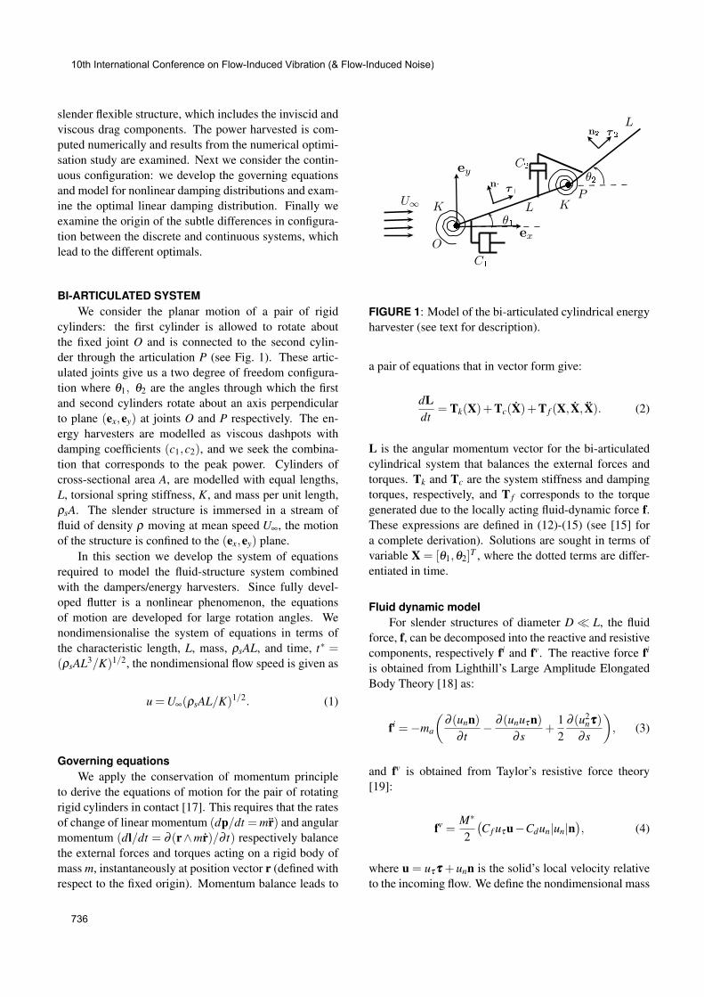
We consider the planar motion of a pair of rigidcylinders: the first cylinder is allowed to rotate aboutthe fixed joint O and is connected to the second cylin-der through the articulation P (see Fig. 1). These artic-ulated joints give us a two degree of freedom configura-tion where θ1, θ2 are the angles through which the firstand second cylinders rotate about an axis perpendicularto plane (ex,ey) at joints O and P respectively. The en-ergy harvesters are modelled as viscous dashpots withdamping coefficients (c1,c2), and we seek the combina-tion that corresponds to the peak power. Cylinders ofcross-sectional area A, are modelled with equal lengths,L, torsional spring stiffness, K, and mass per unit length,ρsA. The slender structure is immersed in a stream offluid of density ρ moving at mean speed U∞, the motionof the structure is confined to the (ex,ey) plane.
In this section we develop the system of equationsrequired to model the fluid-structure system combinedwith the dampers/energy harvesters. Since fully devel-oped flutter is a nonlinear phenomenon, the equationsof motion are developed for large rotation angles. Wenondimensionalise the system of equations in terms ofthe characteristic length, L, mass, ρsAL, and time, t
∗ =(ρsAL
3/K)1/2, the nondimensional flow speed is given as
u =U∞(ρsAL/K)1/2. (1)
Governing equations
We apply the conservation of momentum principleto derive the equations of motion for the pair of rotatingrigid cylinders in contact [17]. This requires that the ratesof change of linear momentum (dp/dt = mr) and angularmomentum (dl/dt = ∂ (r∧mr)/∂ t) respectively balancethe external forces and torques acting on a rigid body ofmass m, instantaneously at position vector r (defined withrespect to the fixed origin). Momentum balance leads to
FIGURE 1: Model of the bi-articulated cylindrical energyharvester (see text for description).
a pair of equations that in vector form give:
dLdt
= Tk(X)+Tc(X)+T f (X, X, X). (2)
L is the angular momentum vector for the bi-articulatedcylindrical system that balances the external forces andtorques. Tk and Tc are the system stiffness and dampingtorques, respectively, and T f corresponds to the torquegenerated due to the locally acting fluid-dynamic force f.These expressions are defined in (12)-(15) (see [15] fora complete derivation). Solutions are sought in terms ofvariable X = [θ1,θ2]T , where the dotted terms are differ-entiated in time.
Fluid dynamic model
For slender structures of diameter D � L, the fluidforce, f, can be decomposed into the reactive and resistivecomponents, respectively fi and fv. The reactive force fi
is obtained from Lighthill’s Large Amplitude ElongatedBody Theory [18] as:
fi =−ma
�∂ (unn)
∂ t− ∂ (unuτn)
∂ s+
12
∂ (u2nτττ)
∂ s
�, (3)
and fv is obtained from Taylor’s resistive force theory[19]:
fv =M
∗
2�Cf uτu−Cdun|un|n
�, (4)
where u = uττττ +unn is the solid’s local velocity relativeto the incoming flow. We define the nondimensional mass
10th International Conference on Flow-Induced Vibration (& Flow-Induced Noise)
736

ratio, M∗ = ρDL/ρsA, and nondimensional added mass,
ma = Ma/ρsA, with Ma as the dimensional added massper unit length. For details on the fluid model refer to[15, 16] and references cited therein. In the remainder ofthe paper, we assume a neutrally buoyant circular cylinder(ρ = ρs, A = πD
2/4, ma = 1) with D/L = 0.1 (M∗ ≈12.7) for all subsequent calculations.
Model of energy harvesting
As noted energy harvesters are modelled in this sys-tem as viscous dashpots, with nondimensionalised coef-ficient ci. To quantify the energy harvesting action weparametrise damping coefficients, ci, and compute thenondimensional power harvested:
P =P
ρDLU3∞= c1�θ 2
1 �+ c2�(θ2 − θ1)2�, (5)
where P is the mean dimensional harvested power andoperator �·� indicates time-averaging over a limit cycleoscillation of period T . In the next section we seek op-timal values of the damping coefficients that yield maxi-mum harvested power, P .
Results:
Eqn. (2) corresponds to a pair of second-order non-linear ordinary differential equations in time with vari-ables θ1, θ2. The equations are solved numerically usinga Runge-Kutta ode45 solver in MATLAB with a rela-tive error tolerance of 10−6. We fix the flow speed asu = 2.45, calculations are initiated with a perturbationfrom the rest state, the integration is stopped if either con-dition θ < π/2 or |θi|< π/2 is violated.
Flutter instabilities in the undamped system
Prior to the analysis of energy harvesting we examine theflutter response of the undamped system (ci = 0) in theabsence of fluid dissipation (Cf =Cd = 0) and in Fig. 2(a)we show the system response to increasing flow speed, u.We calculate a critical flow speed of u
cr ≈ 2.13, belowwhich the fluid acts to damp out disturbances impartedto the system. At u
cr the system undergoes a Hopf bi-furcation and at higher velocities we see steady flutteroscillations. A physical picture of these oscillations areindicated in Fig. 2(b) where we superimpose snapshots ofthe bi-articulated cylinder at different instants during theoscillation cycle.
Power harvesting We now introduce structuraldamping in the configuration and calculate the power P
(a)
(b)
FIGURE 2: (a) Flutter amplitude dependence on the bifur-cation parameter, u (θ2: solid curves; θ1: dotted curves).(b) Flutter response indicated by superimposed snapshotsat discrete time instants during a limit cycle period (atu = 2.2).
FIGURE 3: Power dependence on damping coefficientsc1 and c2 (at u = 2.45, Cf = 0.01, Cd = 1.0).
for combinations of (c1,c2) that yield limit cycle oscilla-tions. We fix the flow speed at u = 2.45, and select repre-sentative values for the drag coefficients (Cf = 0.01, Cd =1.0).
In Fig. 3 we plot the power map in the (c1,c2)-parameter space; also indicated is the stability boundary
10th International Conference on Flow-Induced Vibration (& Flow-Induced Noise)
737
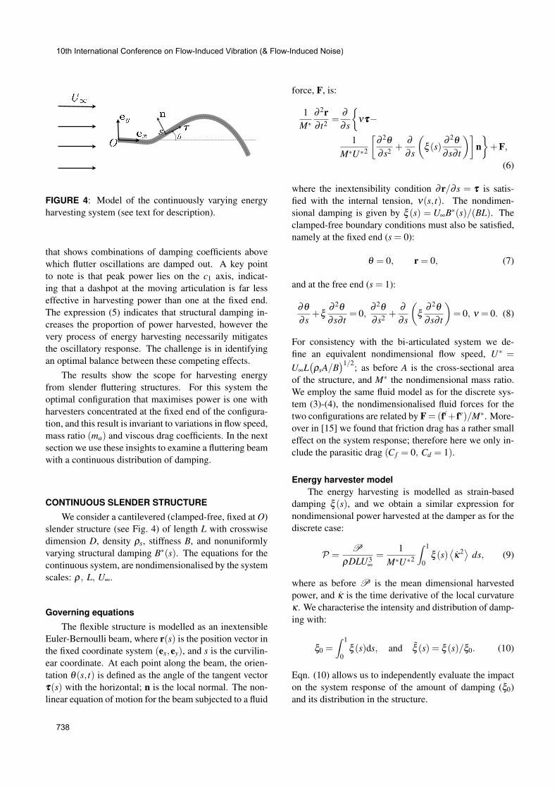
FIGURE 4: Model of the continuously varying energyharvesting system (see text for description).
that shows combinations of damping coefficients abovewhich flutter oscillations are damped out. A key pointto note is that peak power lies on the c1 axis, indicat-ing that a dashpot at the moving articulation is far lesseffective in harvesting power than one at the fixed end.The expression (5) indicates that structural damping in-creases the proportion of power harvested, however thevery process of energy harvesting necessarily mitigatesthe oscillatory response. The challenge is in identifyingan optimal balance between these competing effects.
The results show the scope for harvesting energyfrom slender fluttering structures. For this system theoptimal configuration that maximises power is one withharvesters concentrated at the fixed end of the configura-tion, and this result is invariant to variations in flow speed,mass ratio (ma) and viscous drag coefficients. In the nextsection we use these insights to examine a fluttering beamwith a continuous distribution of damping.
CONTINUOUS SLENDER STRUCTURE
We consider a cantilevered (clamped-free, fixed at O)slender structure (see Fig. 4) of length L with crosswisedimension D, density ρs, stiffness B, and nonuniformlyvarying structural damping B
∗(s). The equations for thecontinuous system, are nondimensionalised by the systemscales: ρ, L, U∞.
Governing equations
The flexible structure is modelled as an inextensibleEuler-Bernoulli beam, where r(s) is the position vector inthe fixed coordinate system (ex,ey), and s is the curvilin-ear coordinate. At each point along the beam, the orien-tation θ(s, t) is defined as the angle of the tangent vectorτττ(s) with the horizontal; n is the local normal. The non-linear equation of motion for the beam subjected to a fluid
force, F, is:
1M∗
∂ 2r∂ t2 =
∂∂ s
�ντττ−
1M∗U∗2
�∂ 2θ∂ s2 +
∂∂ s
�ξ (s) ∂ 2θ
∂ s∂ t
��n�+F,
(6)
where the inextensibility condition ∂r/∂ s = τττ is satis-fied with the internal tension, ν(s, t). The nondimen-sional damping is given by ξ (s) = U∞B
∗(s)/(BL). Theclamped-free boundary conditions must also be satisfied,namely at the fixed end (s = 0):
θ = 0, r = 0, (7)
and at the free end (s = 1):
∂θ∂ s
+ξ ∂ 2θ∂ s∂ t
= 0,∂ 2θ∂ s2 +
∂∂ s
�ξ ∂ 2θ
∂ s∂ t
�= 0, ν = 0. (8)
For consistency with the bi-articulated system we de-fine an equivalent nondimensional flow speed, U
∗ =
U∞L�ρsA/B
�1/2; as before A is the cross-sectional areaof the structure, and M
∗ the nondimensional mass ratio.We employ the same fluid model as for the discrete sys-tem (3)-(4), the nondimensionalised fluid forces for thetwo configurations are related by F= (fi+ fv)/M
∗. More-over in [15] we found that friction drag has a rather smalleffect on the system response; therefore here we only in-clude the parasitic drag (Cf = 0, Cd = 1).
Energy harvester model
The energy harvesting is modelled as strain-baseddamping ξ (s), and we obtain a similar expression fornondimensional power harvested at the damper as for thediscrete case:
P =P
ρDLU3∞=
1M∗U∗2
� 1
0ξ (s)
�κ2�
ds, (9)
where as before P is the mean dimensional harvestedpower, and κ is the time derivative of the local curvatureκ . We characterise the intensity and distribution of damp-ing with:
ξ0 =� 1
0ξ (s)ds, and ξ (s) = ξ (s)/ξ0. (10)
Eqn. (10) allows us to independently evaluate the impacton the system response of the amount of damping (ξ0)and its distribution in the structure.
10th International Conference on Flow-Induced Vibration (& Flow-Induced Noise)
738

(a)
(b)
FIGURE 5: (a) Maximum deflection ymax (solid) and ori-entation θmax (dashed) of the free end as a function offlow speed U
∗. (b) Snapshots of the beam response forU
∗ = 10, 13 and 19 (from top to bottom).
Results
Numerical model Expanding θ in terms of orthog-onal Chebyshev polynomials in s, Eq. (6) is solved nu-merically together with Eqs. (7)–(8), using an iterativesecond-order implicit method in time [20]. In the numer-ical implementation the beam and the fluid are initially atrest; the flow speed is ramped up to its steady state valueand a small perturbation is applied to the vertical flow,and at each time step we ensure conservation of energy issatisfied within an acceptable tolerance (see [16] for de-tails).
Flutter response for an undamped beam As forthe discrete case we first examine the undamped flutter re-sponse and plot the system response for increasing nondi-mensional flow speed in Fig. 5. The critical flow speed atwhich flutter ensues is verified from linear stability anal-ysis. For the energy harvesting computations we choosea flow speed of U
∗ = 13.
(a)
(b)
FIGURE 6: Power computations for a linear damping dis-tribution (11): (a) Power contours P for varying ξ0 andξ1. (b) Rescaled harvested power P/Pmax
has a function of
the damping intensity ξ0 for linearly decreasing (ξ1 =−2,dashed), constant (ξ1 = 0, dotted) and linearly increasing(ξ1 = 2, solid) damping distributions.
Model of energy harvesting Based on the resultsfrom the bi-articulated configuration we seek distribu-tions that are allowed to vary along the length of the beam.Here we examine a simple nonhomogeneous distributionof damping of the form:
ξ (s) = ξ0�1+ξ1(s−1/2)
�(11)
characterised by two coefficients, the total damping,10−3 < ξ0 < 10, and slope, −2 ≤ ξ1 ≤ 2. Operating onthe (ξ0,ξ1)-parameter space, Fig. 6(a) shows the variationof harvested power P . In Fig. 6(b) we plot the rescaledpower P/Pmax
h, where Pmax
his the peak harvested power
for a constant distribution of damping (ξ1 = 0). The fig-ure shows that for ξ1 = 2 the peak harvested power isenhanced by almost 50% compared to the constant distri-bution case. Thus the optimal linear damping distributionis one that increases with distance from the free end.
10th International Conference on Flow-Induced Vibration (& Flow-Induced Noise)
739
We note that the function family (11) correspondsphysically to a dispersed distribution, and the dampingis significant over the entire length of the structure. In-spired by the discrete optimal that has damping concen-trated at the fixed end, in [16] we optimised on a familyof Gaussian distributions, where the mean position on thebeam and the Gaussian spread were the optimisation pa-rameters. Despite these different families of functions weconverged on a dispersed distribution that confirms the re-sults in Fig. 6. Therefore in contrast to the bi-articulatedsystem, for a continuously varying system we find that adispersed distribution of damping generates higher peakpower than a focused distribution.
COMPARISONS AND CONTRASTS: Discrete vs. con-
tinuous systems
In this work, we considered the possibility of har-vesting energy from a slender body fluttering in an axialflow, in particular the impact of harvester-distribution onthe performance of the system and resulting optimisationstrategies. To this end, a simplified fluid-solid model wasproposed with energy harvesting represented as curvaturebased damping.
We first investigated the reduced-order system com-prising of a spring-damper-cylinder pair in an axial flowstream. The model demonstrates the scope for energy har-vesting, furthermore we find that a single harvester posi-tioned at the fixed end can optimally extract power fromthe system. Conversely, an additional dashpot at the mov-ing articulation suppresses the flutter instability and con-siderably diminishes the total harvested power. An inves-tigation of the continuously varying system confirms thescope to harvest energy. However we find that to maxi-mally harvest power, damping that is dispersed along thelength of the beam is superior to a focused distribution.Furthermore, an increasing distribution of damping en-hances the peak harvested power by approximately 50%,over that for a constant distribution.
To reconcile the differing optimal solutions betweenthese two apparently canonical systems, we note that cur-vature in the system drives the instability for both con-figurations. Whilst the bi-articulated system has only onesource of instability (the second articulation), deforma-tions can occur all along the length of the beam in thecontinuous system. As damping acts to suppress the in-stability locally, for the continuous system the flutter in-stability can be maintained as long as the fluttering beamcan adapt to locally rigidify the structure at the positionof high damping. Conversely for the discrete case wherethere is one sole source of curvature that sustains the flut-
ter instability in the entire system, oscillations are quicklysuppressed if damping is added at the same curvature.Thus although the system response to damping is identi-cal in both systems, a careful examination of the dynam-ics of the different configurations is necessary to predictthe optimal harvester distribution.
ACKNOWLEDGMENT
The authors gratefully acknowledge the support ofElectricite de France (EDF) for their support through the“Chaire Energies Durables” at Ecole Polytechnique. S.M. was also supported by a Marie Curie InternationalReintegration Grant within the 7th European CommunityFramework Program.
REFERENCES
[1] Westwood, A., 2004. “Ocean power: Wave and tidalenergy review”. Refocus, 5, pp. 50 – 55.
[2] Falcao, A., 2010. “Wave energy utilization: A re-view of the technologies”. Renew. Sust. Energ. Rev.,
10, pp. 899–918.[3] Anton, S., and Sodano, H., 2007. “A review
of power harvesting using piezoelectric materials(2003-2006)”. Smart Mater. Struct., 16, pp. 1–21.
[4] Grouthier, C., Michelin, S., and de Langre, E., 2012.Optimal energy harvesting by vortex-induced vibra-tions in cables. pre-print, arXiv:1203.0236v1.
[5] Peng, Z., and Zhu, Q., 2009. “Energy harvestingthrough flow-induced oscillations of a foil”. Phys.
Fluids, 21, p. 123602.[6] Tang, L., Paıdoussis, M., and Jiang, J., 2009. “Can-
tilevered flexible plates in axial flow: Energy trans-fer and the concept of flutter-mill”. Journal of Sound
and Vibration, 326, pp. 263–276.[7] Doare, O., and Michelin, S., 2011. “Piezoelec-
tric enegy harvesting from flutter instability: Lo-cal/global linear stability and efficiency”. J. Fluids
Struct., 27, pp. 1357–1375.[8] Paıdoussis, M. P., 2004. Fluid-Structure Interac-
tions: Slender structures and axial Flow, Volume 2.London: Elsevier Academic Press.
[9] Alben, S., and Shelley, M., 2008. “Flapping statesof a flag in an inviscid fluid: bistability and the tran-sition to chaos”. Phys. Rev. Lett., 100, p. 074301.
[10] Michelin, S., Llewellyn Smith, S. G., and Glover,B., 2008. “Vortex shedding model of a flappingflag”. J. Fluid Mech., 617, pp. 1–10.
[11] Crighton, D. G., and Oswell, J. E., 1991. “Fluidloading with mean flow. (I). Response of an elastic
10th International Conference on Flow-Induced Vibration (& Flow-Induced Noise)
740

plate to localized excitation”. Philos. Trans. R. Soc.
London, A, 335, pp. 557–592.[12] de Langre, E., Doare, O., Paıdoussis, M. P., and
Modarres-Sadeghi, Y., 2007. “Flutter of long flex-ible cylinders in axial flow”. J. Fluid Mech., 571,pp. 371–389.
[13] Paıdoussis, M. P., Grinevich, E., Adamovic, D., andSemler, C., 2002. “Linear and nonlinear dynamicsof cantilevered cylinders in axial flow. Part 1. Phys-ical dynamics”. J. Fluids Struct., 16, pp. 691–713.
[14] Paıdoussis, M. P., 1998. Fluid-Structure Interac-
tions: Slender structures and axial flow, Volume 1.London: Academic Press.
[15] Singh, K., Michelin, S., and de Langre, E., 2012.“Energy harvesting from fluid-elastic instabilities ofa cylinder”. J. Fluids Struct., 30, pp. 159–172.
[16] Singh, K., Michelin, S., and de Langre, E., 2012.“Effect of damping on flutter in axial flow and opti-mal energy harvesting”. (under review).
[17] Landau, L. D., and Lifshitz, E. M., 1976. Mechan-
ics, third ed., Vol. Volume 1 of Course of TheoreticalPhysics. Elsevier Ltd.
[18] Lighthill, M. J., 1971. “Large-amplitude elongated-body theory of fish locomotion”. Proc. R. Soc. B,
179, pp. 125–138.[19] Taylor, G. I., 1952. “Analysis of the swimming of
long and narrow animals”. Proc. R. Soc. A, 214,pp. 158–183.
[20] Alben, S., 2009. “Simulating the dynamics of flexi-ble bodies and vortex sheets”. J. Comp. Phys., 228,pp. 2587–2603.
Appendix A: Expressions for the discrete system
The terms in Eqs. (2) are defined in this section. Wedefine the rate of change of angular momentum aboutpoint P and O respectively as:
Lp =
�θ2
3+
θ1
2cos(θ2 −θ1)+
θ 212
sin(θ2 −θ1)
�,
Lo = L
p +
�4θ1
3+
θ2
2cos(θ2 −θ1)−
θ 222
sin(θ2 −θ1)
�,
(12)
and dL/dt = [Lo − Lp, Lp]T . Note that this recombination
of the two equations leads to significantly simpler expres-sions.
The contribution from the restoring torsional springsis linear thus the angular moment transferred to the joints
is given as,
Tp
k=−(θ2 −θ1),
To
k=−θ1 = T
p
k− (2θ1 −θ2). (13)
and Tk = [T o
k−T
p
k,T p
k]T .
From the Kelvin-Voigt model the angular momenttransferred to the joints for dampers with coefficients, c1and c2 at P and O respectively are:
Tp
c =−c2(θ2 − θ1),
To
c =−c1θ1,
= Tp
c −�c1θ1 − c2(θ2 − θ1)
�, (14)
and Tc = [T oc −T
p
c ,Tp
c ]T .
Fluid torque vector T f = T f ,v +T f ,i, where the firstterm is the contribution from the viscous drag or resistiveforces and the second term is the inviscid or reactive forcecontribution. For brevity we do not include the viscouscomponents. The contribution of the reactive flow forcesto the fluid torques at the two articulations is given by,
Tp
f ,i =−ma
�θ1
�θ1
2− θ2
�sin(θ2 −θ1)+
θ1
2cos(θ2 −θ1)
+θ2
3+ucosθ2θ2
�,
To
f ,i = Tp
f ,i −ma
�θ1
�13+ cos2(θ2 −θ1)
�+
θ2
2cos(θ2 −θ1)
+ θ1
�θ1
2− θ2
�sin2(θ2 −θ1)
+u�θ1 cosθ1 +2θ2 cosθ2 cos(θ2 −θ1)
��+T
jump,
(15)
where ma is the nondimensionalised added mass. Tjump
is the contribution of the inviscid fluid dynamics over thecorner, P, is:
Tjump =−ma
�ao +a1u+a2u
2� (16)
10th International Conference on Flow-Induced Vibration (& Flow-Induced Noise)
741

where
ao =θ 2
12
�− cos2(θ2 −θ1)sin(θ2 −θ1)
�,
a1 = θ1
�cos2(θ2 −θ1)cosθ2 − cosθ1
�
a2 =12
�sinθ2 cosθ1 +
12
sin2θ2 cos(θ2 −θ1)
− sin2θ1
�(17)
and the inviscid fluid moment vector is,T f ,i = [T o
f ,i −Tp
f ,i,Tp
f ,i]T .
10th International Conference on Flow-Induced Vibration (& Flow-Induced Noise)
742