energy efficiency of flights rotary kiln -...
TRANSCRIPT
14th Quantitative InfraRed Thermography Conference
License: https://creativecommons.org/licenses/by-nd/4.0/deed.en
Energy efficiency of flights rotary kiln
by F. Huchet*, L. Le Guen*
* Ifsttar, The French Institute of Science and Technology for Transport, Development and Networks, MAST/GPEM, Allée des Ponts et Chaussées, CS 5004, 44 344 Bouguenais cedex, [email protected]
Abstract
Rotary kiln is widespread for thermal treatment of granular materials in various industries. A better understanding of the heat transfer phenomena, inside, and outside of the industrial rotary kiln will open toward the development of sustainable tools of production such as materials recycling or heat waste recovery. The present paper details two examples about the interest brought by the IR measurements to rely the external wall temperature to the thermal behavior of rotary kiln. A special attention is given to the energy efficiency from a thermal model suited to industrial application as encountered in the asphalt plants.
1. Introduction
Rotary kiln is widespread for thermal treatment of granular materials such as drying, gasification, heating, pyrolysis, sintering, calcination, roasting and cooling in various industries. Slightly inclined, a hollow cylindrical apparatus rotates around its central axis. The dimensions can be up to 230 m length and up to 7 m inner diameter. The temperature range of these processes extends from 100°C to 2000°C, whereas the kilns can be heated directly (from inside) or indirectly (from outside). The carbon footprint of these facilities can be considered as no negligible such as encountered in the cement production sector where the wall heat losses can reach 61% of the overall energy losses [1]. A better understanding of the heat transfer phenomena inside and outside of the industrial rotary kiln would open toward the development of sustainable tools of production to promote materials recycling or heat waste valorization.
One industrial flights rotary kiln, so called asphalt plant, has recently attracted many interests because of its use
in the pavement application, which require enough workability to setup asphalt materials. Such process involves a momentum transfer linked to the granular motion that has been well identified in experimental [2] and numerical works [3]. This highly energy-intensive process consists of three manufacturing stages. The drying and heating of mineral stones are performed before the mixing with the bitumen binder at a temperature ranged between 100° C and 160°C. The solid mass fraction is generally equal to 0.95. To perform the heating stage, the aggregates are conveyed within the slightly titled rotary drum. It is equipped with baffles, which generate a cascading regime of the aggregates and a granular bed at the bottom. The granular flow behaviour ensures the drying and heating stages by promoting the contact with the hot gases. A burner located at the inlet of the drum (Fig.1) provides the hot gases. These hot combustion gases in turn provide the heat required for the water vaporization and heating of the aggregates. At the end of the heating zone, the aggregates are in an appropriate condition to be mixed with bitumen until reaching a temperature of asphalt concrete.
Fig. 1. Scheme of a continuous mixing asphalt plant. Momentum and heat transfers (��𝑗
𝑖) act differently according to the
axial position of the flight rotary kiln. A combination of the radiation and convective transfers (i=R or C) occurs between each phase (j=s, b, c for granular solid, bed, curtain and j=w, g, e for the wall, the gases and exterior).
In order to understand the heat transfer phenomena and to recover heat losses, an energy analysis was proposed to model the process by taking into account the granular behaviour [4], and so, the exchange surface, 𝑑𝑆. The process simulation in steady state is achieved from two equations derived from an energy budget including convective and radiation phenomena (𝜙𝑅𝑎𝑑) established in a slice of the rotary kiln on the gases and aggregates phases:
10.21611/qirt.2018.034
QIRT 2018 Proceedings Page: 430

14th Quantitative InfraRed Thermography Conference, 25 – 29 June 2018, Berlin, Germany
��𝑔𝑐𝑝𝑔𝑑𝑇𝑔 = ℎ𝑔𝑤𝑑𝑆𝑔𝑤(𝑇𝑤 − 𝑇𝑔) + ∑ ℎ𝑔𝑗𝑑𝑆𝑔𝑗(𝑇𝑔 − 𝑇𝑗)𝑗=𝑐,𝑏 +𝜙𝑅𝑎𝑑 (1) ��𝑠𝑐𝑝𝑠𝑑𝑇𝑎 = ℎ𝑠𝑤𝑑𝑆𝑠𝑤(𝑇𝑤 − 𝑇𝑠) + ∑ ℎ𝑔𝑗𝑑𝑆𝑔𝑗(𝑇𝑔 − 𝑇𝑗)𝑗=𝑐,𝑏 + 𝜙𝑅𝑎𝑑 (2)
Among the many heat transfer coefficients, the aggregates/wall and the freeboard gases/wall exchanges govern the heat fluxes from the interior to the exterior of the system. By averaging in a slice, one can define an inner global heat transfer coefficient, hi, composed of the heat exchanges between the multi-phase flow (including the particulates system and the freeboard gases) with the inner wall of the drum. The inner wall heat transfer coefficient is defined as follows:
ℎ𝑖 =1
2𝜋∙ (ℎ𝑔𝑤 ∙ (2𝜋 − 𝛽) + 𝛽 ∙ ℎ𝑠𝑤 ∙
𝑇𝑠−𝑇𝑖𝑤
𝑇𝑔−𝑇𝑖𝑤) (3)
With 𝛽 being a tuning parameter for the area of transfer between the wall and the gases, and between the aggregates and the wall as referred in preceding work [5]. To estimate hi, a suited monitoring of an industrial plant has been performed to record the temperature evolution of the phases flowing through the drum knowing that the inner wall temperature, 𝑇𝑖𝑤, is not directly measurable.
The characterization of the thermal behavior is herein addressed by relying the external shell temperature to the
full heat transfer mechanisms occurring in such flight rotary kiln. The experimental results are compared to the results of the literature supported by numerical simulations and semi-empirical models. The second study is devoted to the heat waste recovery at the external shell surface of the rotary kiln. Scaled at 1:5, a second insulated shell mounted to a lab-scale kiln have been instrumented to explore a large range of experimental conditions.
2. Heat transfer coefficient evaluation in real system
Four asphalt materials productions corresponding to several solid feed rates were planned in an industrial plant (Fig. 2). The thermal characterization of the multi-phase flow where performed at six axial position, z, along the drum. An accurate explanation of this experimental study is available in the work of Le Guen et al. [5]. It is important to emphasize that the temperatures of the external shell were captured by a thermal Infra-Red Camera (Fig. 2).
Fig. 2. Large-scale view of the rotary drum with the infrared camera FLIR A320. Recycled materials can be fed at the
middle of the drum in a restricted area by means of a second shell.
The external wall temperature, Tew , is monitored by two infrared camera. The FLIR A320 has been devoted to large-scale view and the FLIR E30 has been used at each position corresponding to the measurements of the solid and gaseous phases. A one dimensional heat balance between the air exterior, the drum and the interior leads to the elimination of 𝑇𝑖𝑤 to get a fourth order equation such as :
𝑎. 𝑇𝑒𝑤4 + 𝑏𝑇𝑒𝑤 + 𝑐 = 0 (4)
a, b and c depending only of known physical parameters (emissivity, conductivity and the external heat transfer coefficient) and the unknown inner heat transfer coefficient.
The resolution of this equation is based on the Ferrari-Cardan method leading to the evaluation of Tew(hi). Compared to the experimental value, TewIR, measured from infrared camera, the best evaluation of hi for each production
corresponds to the minimization of a cost function, f, given by:
𝑓 = [𝑇𝑒𝑤(ℎ𝑖) − 𝑇𝑒𝑤𝑚𝑒𝑎𝑠𝑢𝑟𝑒𝑑]2 (5)
As shown in figure 2, the drum geometry induces variation of the mass flow rates of the multi-phases system. Indeed, a second granular feed system located at z=2.36 m from the combustion chamber is able to deliver recycled materials flow rate corresponding to 20% of the inlet solid mass flow rate. It has been shown that the feeding system affect the heat transport behaviour such as:
- The use of recycled materials gives rise to a temperature augmentation as discussed in a recent paper [6], - a secondary air flow passage is responsible of the wall cooling when none recycled materials is formulated.
10.21611/qirt.2018.034
QIRT 2018 Proceedings Page: 431
14th Quantitative InfraRed Thermography Conference, 25 – 29 June 2018, Berlin, Germany
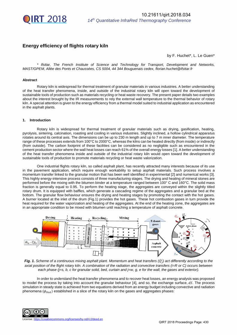
Let us consider this second case (Fig. 2), a secondary airflow from the exterior increase the Reynolds number from 105 to 4. 105. Consequently, the inner heat transfer coefficient, hi, is raised from 15 W.m-2K-1 to 150 W.m-2K-1 after the feeding system corresponding to the wall cooling measured from the wall temperature. Similar trend has been reported in multi-holes system positioned downstream to a combustion chamber [7-8].
Fig. 3. Heat transfer coefficient, hi, measured in large-scale kiln at different aggregates feed rate (circle: 𝑚𝑎 = 26 kg.s-1-
triangle: 𝑚𝑎 = 29 kg.s-1 – diamond: 𝑚𝑎 = 31 kg.s-1 – square: 𝑚𝑎 = 34 kg.s-1).
Each kind of flow, i.e. aggregates and secondary exterior air flow have to be considered as cold source while the combustion gases have to be considered as a mean hot source. Consequently, the heat transport balance is better suited to predict the longitudinal wall heat transfer coefficient from a ratio based on the thermal flow rates:
��𝑐⋅𝐶𝑝𝑐
��ℎ⋅𝐶𝑝ℎ (6)
Fig. 4. Modelled Nusselt numbers describing the inner wall heat transfer in the heating zone measured in large-scale kiln at different aggregates feed rate (circle : ma = 25 kg.s-1; triangle: ma = 29 kg.s-1 ; diamond : ma = 31 kg.s-1; square : 34 kg.s-1). The chart is plotted in dimensionless numbers in such way, that the length of the drum is divided by its diameter.
Consequently, a suitable relationship between the Nusselt number and the working parameters of the processes can be derived from the Stanton number such as:
𝑁𝑢 = 0.032 ⋅ 𝑅𝑒0.8 ⋅ 𝑆𝑡0.3 ⋅ (1 + (𝐷
𝑧)0.7) ⋅ (
��𝑐⋅𝐶𝑝𝑐
��ℎ⋅𝐶𝑝ℎ) (7)
With 𝑁𝑢 = ℎ𝑖⋅𝜋⋅𝐷1
��𝑎⋅��𝑔(��𝑔⋅𝜆𝑔+��𝑎⋅𝜆𝑎)
and 𝑆𝑡 = ℎ𝑖
𝑣𝑔⋅𝜌𝑔⋅𝐶𝑝𝑔
Burner
Inlet solidsfeeding
mcCpc Systemfeeding
mhCph
0
50
100
150
200
250
0 1 2 3 4 5
h i (W
.m-2
.K-1
)
z (m)
100
1000
0.5 1 1.5 2 2.5 3
Nu
z/D
= . ⋅ . ⋅ . ⋅ +
.
⋅ ⋅
⋅
Fe
ed
ing
syste
m
10.21611/qirt.2018.034
QIRT 2018 Proceedings Page: 432
14th Quantitative InfraRed Thermography Conference, 25 – 29 June 2018, Berlin, Germany
𝑣𝑔 ⋅ 𝜌𝑔 ⋅ 𝐶𝑝𝑔 being the thermal flow rates provided by the hot gases governing the convective exchange (hi) between the two-phase flow and the drum wall. Consequently, a simple expression given by the equation (7) has been proposed to fit the experimental results. The calculated Nusselt numbers are in good agreement with the measured Nusselt numbers. The measured Nusselt numbers ranged between 99 and 1070, and those of the calculated Nusselt numbers are ranged from 110 to 830. The relative mean deviation is equal to 23%
3. Heat waste recovery
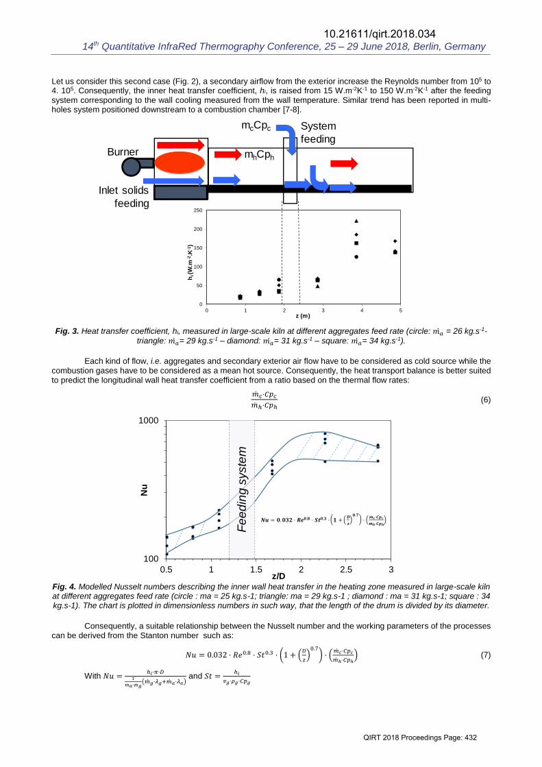
Recently, it has been shown that heat waste recovery system could bring large benefits in terms of energy efficiencies. The present section is devoted to the valorisation of the heat waste in rotary kiln such as previously studied. It requires a secondary shell mounted up to the rotary kiln. Experimental measurements established at pilot-scale and numerical simulations are able to characterize the efficiency of this complex system composed of:
- A multiphase flow including energy exchanges between the solid matter, the gases flow and the wall, - a air heat recovery system where this energy exchanges are transferred through the wall kiln.
3.1. Experimental pilot-scale
As shown in figure 5, it has been chosen to work at identical external wall temperature than those measured at industrial-scale (70<Twall<150 °C). Consequently, two half-cylinders have been made to form an insulated annular heat exchanger of a diameter equal to Dexch=0.42 m and of length LD=0.905 m. Two electrical resistances are located into the inner moving cylinder (D=0.34 m) which is able to mimic the energy exchanges between the particulates flow and the inner moving wall at a rotational velocity, 𝜔.
Fig. 5: Air-cooled heat exchanger working in natural and forced draft condition is composed of an inner moving cylinder
surrounded by two half-cylinders.
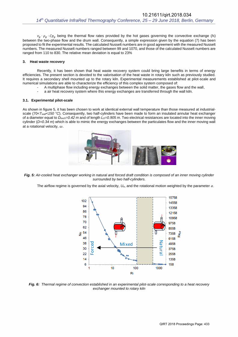
The airflow regime is governed by the axial velocity, Ua, and the rotational motion weighted by the parameter 𝛼.
Fig. 6: Thermal regime of convection established in an experimental pilot-scale corresponding to a heat recovery exchanger mounted to rotary kiln
Natural
Mixed
Forced
10.21611/qirt.2018.034
QIRT 2018 Proceedings Page: 433
14th Quantitative InfraRed Thermography Conference, 25 – 29 June 2018, Berlin, Germany
The thermal convection regimes are presented in Fig. 6 exhibiting several regimes from Natural, Mixed to Forced convection according to the Richardson and the effective Reynolds numbers defined by:
𝑅𝑖 =𝐺𝑟
𝑅𝑒𝑒𝑓𝑓2 (8)
With Gr = 𝛽(𝑇𝑤𝑎𝑙𝑙 − 𝑇𝑏𝑢𝑙𝑘 𝑎𝑖𝑟)(𝐷𝑒𝑥𝑐ℎ)3 𝜈2⁄ And 𝑅𝑒𝑒𝑓𝑓 = ((��𝑎𝑥
2 + 𝛼(𝜔 (𝐷 2)⁄ 2))
1/2× 𝐷ℎ) 𝜈⁄
The experimental apparatus is detailed in [10] and semi-empirical correlations have been deduced in that large
range of flow regimes which are depicted in the table 1.
Table 1: Correlations established in the heat recovery exchanger depending on the Rayleigh number in natural convection and the effective Reynolds Number in mixed and forced convection.
Thermal convection regimes Flow regimes Nusselt numbers Natural convection 𝑅𝑒𝑒𝑓𝑓 < 600
3.107 < 𝑅𝑎 < 5.109 𝑁𝑢𝑒𝑥𝑐ℎ = 0.0113 𝑅𝑎0.38
Mixed convection 650 ≤ 𝑅𝑒𝑒𝑓𝑓 ≤ 10000 𝑁𝑢𝑒𝑥𝑐ℎ = 0.3[𝑅𝑒𝑒𝑓𝑓(𝛼)]0.6
with 𝛼 = 0.038 Forced convection Reeff > 10000
3.2. Process simulation : Rotary Kiln and Heat exchanger
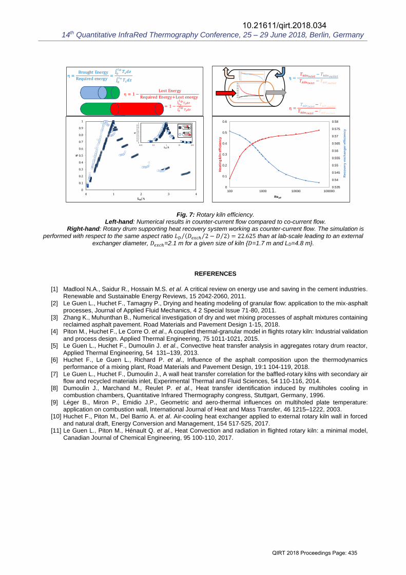
The simulation of the process at the industrial-scale can be solved from the equations (1) and (2). Without the use of heat recovery exchanger, the system of equations is reduced to two equations for aggregates and gases phases. The numerical model is able to compute a large range of size of drum, LD, to predict the optimal kiln size, 𝐿𝜈 = Λ for the desired asphalt materials temperature 𝑇𝑎(𝐿𝜈). As expected, the ratio 𝐿𝜈 Λ⁄ for counter-current is found herein lower that co-current technology [11] as shown in the left-hand of the figure 7.
The efficiency criteria of the complex system {kiln+exchanger} requires to be calculated differently. Herein, we
propose to treat this energy system from the heat exchanger theory by using the logarithmic mean temperature difference (LMTD). This approach can be supposed valid for the air flowing into the exchanger while in the rotary kiln, it requires estimating the mixing-cup temperature of the particulates flows at the inlet and outlet, and an effective thermal flow rate:
𝑇𝑘𝑖𝑙𝑛𝑖𝑛𝑙𝑒𝑡 =𝑇𝑎(𝑧=0)+𝑇𝑔(𝑧=0)
2 ; 𝑇𝑘𝑖𝑙𝑛𝑜𝑢𝑡𝑙𝑒𝑡 =
𝑇𝑎(𝑧=𝐿𝐷)+𝑇𝑔(𝑧=𝐿𝐷)
2 and κ= ��𝑔𝐶𝑝,𝑔∙��𝑎𝐶𝑝,𝑎
��𝑔𝐶𝑝,𝑔+��𝑎𝐶𝑝,𝑎 (9) (10) (11)
Among these latter parameters, the air temperature into the exchanger remains unknown. Therefore, we propose to add two others equations into the system such as:
��𝑎𝑖𝑟𝑐𝑝𝑎𝑖𝑟𝑑𝑇𝑎𝑖𝑟 = ℎ𝑒𝑥𝑐ℎ𝑑𝑆𝑖𝑛𝑛𝑒𝑟(𝑇𝑤 − 𝑇𝑎𝑖𝑟) (12)
A closure equation is applied for the wall temperature such as:
ℎ𝑠𝑤𝑑𝑆𝑠𝑤(𝑇𝑤 − 𝑇𝑠) + ℎ𝑔𝑤𝑑𝑆𝑔𝑤(𝑇𝑤 − 𝑇𝑔)+ℎ𝑒𝑥𝑐ℎ𝑑𝑆𝑖𝑛𝑛𝑒𝑟(𝑇𝑤 − 𝑇𝑎𝑖𝑟)=0 (13)
The numerical integration according to the longitudinal direction is able to reproduce the inner temperature of the aggregates, gases, wall and air flowing within the exchanger as shown in the right-hand of the figure 7.
4. Conclusion
The rotary kiln modelling is herein addressed from the use of InfraRed thermography at different scales in order to assess relevant convective heat transfer coefficients such as:
-The internal heat transfer coefficient including the granular solid-to-wall and gases-to-wall heat exchanges. A semi-empirical correlation is proposed exhibiting upper values of the Nusselt numbers downstream of a feeding system devoted to recycling materials.
-the external heat transfer between the rotary kiln wall and a heat recovery system in a large range of convective regime from natural, mixed and forced convection. Semi-empirical correlations are easily applicable for heat transfer modelling.
These relationships are suited to a one-dimensional model of rotary kiln applied to asphalt materials production.
The numerical computation are herein expanded to the counter-current technology. The use of a heat recovery system as outer shell mounted up to the kiln is very promising for energy consumption reduction.
10.21611/qirt.2018.034
QIRT 2018 Proceedings Page: 434
14th Quantitative InfraRed Thermography Conference, 25 – 29 June 2018, Berlin, Germany
Fig. 7: Rotary kiln efficiency. Left-hand: Numerical results in counter-current flow compared to co-current flow.
Right-hand: Rotary drum supporting heat recovery system working as counter-current flow. The simulation is
performed with respect to the same aspect ratio 𝐿𝐷 (𝐷𝑒𝑥𝑐ℎ 2⁄ − 𝐷 2⁄ ) = 22.625⁄ than at lab-scale leading to an external
exchanger diameter, 𝐷𝑒𝑥𝑐ℎ=2.1 m for a given size of kiln {𝐷=1.7 m and LD=4.8 m}.
REFERENCES
[1] Madlool N.A., Saidur R., Hossain M.S. et al. A critical review on energy use and saving in the cement industries. Renewable and Sustainable Energy Reviews, 15 2042-2060, 2011.
[2] Le Guen L., Huchet F., Tamagny P., Drying and heating modeling of granular flow: application to the mix-asphalt processes, Journal of Applied Fluid Mechanics, 4 2 Special Issue 71-80, 2011.
[3] Zhang K., Muhunthan B., Numerical investigation of dry and wet mixing processes of asphalt mixtures containing reclaimed asphalt pavement. Road Materials and Pavement Design 1-15, 2018.
[4] Piton M., Huchet F., Le Corre O. et al., A coupled thermal-granular model in flights rotary kiln: Industrial validation and process design. Applied Thermal Engineering, 75 1011-1021, 2015.
[5] Le Guen L., Huchet F., Dumoulin J. et al., Convective heat transfer analysis in aggregates rotary drum reactor, Applied Thermal Engineering, 54 131–139, 2013.
[6] Huchet F., Le Guen L., Richard P. et al., Influence of the asphalt composition upon the thermodynamics performance of a mixing plant, Road Materials and Pavement Design, 19:1 104-119, 2018.
[7] Le Guen L., Huchet F., Dumoulin J., A wall heat transfer correlation for the baffled-rotary kilns with secondary air flow and recycled materials inlet, Experimental Thermal and Fluid Sciences, 54 110-116, 2014.
[8] Dumoulin J., Marchand M., Reulet P. et al., Heat transfer identification induced by multiholes cooling in combustion chambers, Quantitative Infrared Thermography congress, Stuttgart, Germany, 1996.
[9] Léger B., Miron P., Emidio J.P., Geometric and aero-thermal influences on multiholed plate temperature: application on combustion wall, International Journal of Heat and Mass Transfer, 46 1215–1222, 2003.
[10] Huchet F., Piton M., Del Barrio A. et al. Air-cooling heat exchanger applied to external rotary kiln wall in forced and natural draft, Energy Conversion and Management, 154 517-525, 2017.
[11] Le Guen L., Piton M., Hénault Q. et al., Heat Convection and radiation in flighted rotary kiln: a minimal model, Canadian Journal of Chemical Engineering, 95 100-110, 2017.
0
0.1
0.2
0.3
0.4
0.5
0.6
0.7
0.8
0.9
1
0 1 2 3 4
η
LD/Λ
00.10.20.30.40.50.60.70.80.91
0.01 0.1 1 10 100
η
LD/Λ
= r er
Re re e er = 𝑇𝑠𝑑 𝐿𝐷0
𝑇𝑠𝑑 𝐿 0
= 1 − er
Re re er + e er
= 1 − 𝑇𝑠𝑑𝑧 𝐷
𝑇𝑠𝑑𝑧 𝐷
= 𝑇𝑘𝑖𝑙𝑛𝑖𝑛𝑙𝑒𝑡 − 𝑇𝑘𝑖𝑙𝑛𝑜𝑢𝑡𝑙𝑒𝑡𝑇𝑘𝑖𝑙𝑛𝑖𝑛𝑙𝑒𝑡 − 𝑇𝑎𝑖𝑟𝑜𝑢𝑡𝑙𝑒𝑡
= 𝑇𝑎𝑖𝑟𝑖𝑛𝑙𝑒𝑡− 𝑇𝑎𝑖𝑟𝑜𝑢𝑡𝑙𝑒𝑡𝑇𝑘𝑖𝑙𝑛 𝑖𝑛𝑙𝑒𝑡 −𝑇𝑎𝑖𝑟𝑜𝑢𝑡𝑙𝑒𝑡
0.535
0.54
0.545
0.55
0.555
0.56
0.565
0.57
0.575
0.58
0
0.1
0.2
0.3
0.4
0.5
0.6
100 1000 10000 100000
Rec
over
y ex
chan
ger e
ffici
ency
Hea
ting
kiln
effi
cien
cy
Reeff
0
40
80
120
160
200
240
280
0
100
200
300
400
500
600
700
800
900
10.21611/qirt.2018.034
QIRT 2018 Proceedings Page: 435