energy efficiency in commercial buildings
TRANSCRIPT

Energy Efficiency in Commercial Buildings
A dissertation presented in fulfillment of the
requirements for the degree of Master of Science
Sustainable Engineering: Energy Systems & the Environment
Ayman Khalid Elsadig
June 2005
Faculty of Engineering
Department of Mechanical Engineering
Energy Systems Research Unit
University of Strathclyde

Copyright Declaration
The copyright of this thesis belongs to the author under the terms of the United Kingdom
Copyright Acts as qualified by the University of Strathclyde Regulation 3.49. Due
acknowledgement must always be made of the use of any material contained in, or
derived from this thesis.
2

Acknowledgements
I would like to express my gratitude to the Department of Mechanical Engineering which
gave me the opportunity to study and extend my knowledge and experience at the Energy
Systems Research Unit (ESRU), of the University of Strathclyde.
Special thanks are due to my supervisor, Ms Lori McElroy, for being so generous to me
with her time, patience, advice and valuable opinion.
For valuable assistance throughout the course I would like to express appreciation to
Prof. Joseph Clarke of the Department of Mechanical Engineering, who offered many
recommendations regarding its structure and contents.
My thanks are extended to the my parents and all my friends I care to name.
3

“ Engineering is the science of economy, of conserving the
energy, kinetic and potential, provided and stored up by nature for the use of
man. It is the business of engineering to utilize this energy to the best advantage, so
that there may be the least possible waste.”
William A. Smith, 1908
4

Abstract
The demand for energy keeps rising which requires the generation of vast amounts of
electricity. Changes have been made to make buildings more energy efficient.
Understanding the use of energy in buildings requires an insight into the amounts of
energy consumed and the different types fuels used. Buildings that could help contribute
to their energy demand through the generation of renewable energy would help reduce
the amounts of Carbon Dioxide (CO2) produced by the building. Hence to succeed in
developing a sustainable society buildings will always need to be improved as technology
improves.
The objective of this dissertation is to obtain a clear understanding of energy efficiency in
buildings and specifically in commercial buildings outlining what would be the most
feasible renewable technique to be adopted in commercial buildings, although there is a
large amount of information available about energy efficiency in commercial buildings of
which some are contradictory.
There are many renewable technologies available at present, of which some had
succeeded and other didn’t, succeeded in a sense of acceptability from the consumer of
the building, for example in commercial buildings overheating is an issue that has to be
tackled, the different case studies provided will assist in evaluating the benefits of each
technology and to what extent it made an impact on the design features, construction and
subsequent use.
Therefore the aim is to construct a review of the most recent consultations on what are
the current trends achieved towards making buildings more intelligent, self-sufficient and
what could be done to make buildings more sustainable. The energy performance of a
building will directly impact on the resale and rental income of the building. The energy
performance of buildings will be discussed in later chapters of this dissertation.
5
Table of Contents
Page
Acknowledgements 3
Abstract 5
Table of Contents 6
List of Figures 10
List of Tables 12
List of Abbreviations 13
CHAPTER ONE: INTRODUCTION
1.1 Introduction and Background 14
1.2 Energy efficiency 14
1.3 Problem Definition 16
CHAPTER TWO: HISTORICAL OVERVIEW OF ENERGY USE IN
BUILDINGS
2.1 Introduction 19
2.2 Energy Efficiency in Buildings 19
2.2.1 Energy Conservation 21
2.2.2 Growth in Energy use in the Developed World 21
2.2.3 Energy use in Hot Climates / Developing countries 23
2.2.4 Addressing the need to Conserve Energy 24
2.3 Energy Performance 25
2.3.1 Energy Consumption 26
2.3.2 Building Regulations 27
2.4 EU Energy Policy: Energy Performance of Buildings Directive 28
2.4.1 Recommendation 28
2.4.2 Implementation 29
2.4.3 Status 30
2.5 Fabric Issues 30
6

2.5.1 Winter versus Summer R-values 31
Page
CHAPTER THREE: PASSIVE RENEWABLE TECHNOLOGY
3.1 Building Design 33
3.2 Passive Renewable Energy use in Buildings 34
3.2.1 Passive Solar Energy 34
3.2.2 Passive Solar Heating 35
3.2.2.1 General 35
3.3 Direct and Indirect Gain Systems 37
3.3.1 Direct Gain 37
3.3.2 Indirect Gain 40
3.3.3 Case Studies 42
3.3.3.a The Wallasey School Case Study 42
3.3.3.b The Pennyland Case Study 47
3.4 Passive Solar Cooling 49
3.4.1 Natural Ventilation 50
3.4.2 High Thermal Mass 50
3.4.3 High Thermal Mass with Night Ventilation 51
3.4.4 Evaporative Cooling 51
3.4.5 Case Studies 51
3.4.5.1 The Queens Building, De Montfort University Case Study
3.4.5.1a Central Building 53
3.4.5.1b Mechanical Laboratories 53
3.4.5.1c Electrical Laboratories 54
3.4.5.1d Servicing Strategies 55
(i) Ventilation 55
(ii) Day Lighting 56
3.4.5.2 Building Services 57
3.4.5.2a Space Heating and Domestic Hot Water 57
3.4.5.2b Electric Lighting 57
3.4.5.2c Building Energy Management System 57
7

3.4.5.2d Energy Use 57
Page
3.4.5.2e Costs 59
3.5 Day lighting 60
3.5.1 The Stansted Airport Terminal Case Study 61
3.5.1.1 The Technology 63
3.5.1.1a Technical barriers 64
3.5.1.1b Market barriers 65
3.5.1.1c Financial barriers 65
3.5.1.1d Price distortions 66
3.5.1.1e Regulations 66
3.5.1.1f Other non technical issues 66
3.6 Summary 66
CHAPTER FOUR: INTEGRATED ‘ACTIVE’ RENEWABLES & NOVEL
SYSTEMS
4.1 Small Scale Integrated Renewable Technologies 68
4.1.1 Solar Photovoltaics 68
4.1.1.1 The Oberlin College Case Study 71
(i) Building Systems 74
(ii) Energy 74
(iii) Indoor Air Quality 75
(iv) Heat Recovery 76
(v) Insulation and Windows 76
4.2 Benefits of PV Systems 77
4.3 Local energy Generation 78
4.3.1 Solar Water Heating 78
4.3.2 Ducted Wind Turbines 80
4.3.2.1 The Lighthouse Case Study 82
4.3.3 Combined Heat and Power (CHP) 84
(a) Micro CHP 85
8

(b) Small Scale CHP 86
Page
(c) Large Scale CHP 86
4.3.3.1 The University of Liverpool Case study 86
(1.) Benefits of CHP 92
(2.) Barriers to Implementing CHP 92
(3.) Potential for Expanding CHP in Europe 94
4.4 Summary 94
CHAPTER FIVE: DISCUSSION, CONCLUSIONS & FUTURE
RECOMMENDATIONS
5.1 Discussion 95
5.2 Conclusion 96
5.3 Recommendations for Future Work 98
5.3.1 Major recommendations 98
9

List of Figures
Page
Figure 2.1 Energy use in commercial buildings 20
Figure 2.2 Percentage distribution of energy consumption 20
Figure 2.3 Conduction 31
Figure 2.4 Winter versus summer R-values 32
Figure 3.1 Design Strategy 36
Figure 3.2 Direct gain solar system 38
Figure 3.3 Clerestory windows 38
Figure 3.4 Overhang 38
Figure 3.5 Louvered Panels 40
Figure 3.6 Trombe wall 41
Figure 3.7 The Wallasey school 43
Figure 3.8 Cross-section of the Wallasey school 43
Figure 3.9 Energy consumption for a typical UK school 44
Figure 3.10 Energy cost for a typical UK school 45
Figure 3.11 Passive solar housing at Pennyland 47
Figure 3.12 The view at the northern side 47
Figure 3.13 Plans for the solar housing at Pennyland 48
Figure 3.14 Design steps in low energy housing 48
Figure 3.15 Side view of the De Montfort University city campus 52
Figure 3.16 The natural ventilation strategy in the building 52
Figure 3.17 The interior of the central building 53
Figure 3.18 Section through the mechanical laboratories 54
Figure 3.19 Section through electrical laboratories 55
Figure 3.20 Air enters the auditorium via plena 56
Figure 3.21 Annual energy consumption 58
Figure 3.22 Annual CO2 emissions 58
Figure 3.23 Comparison in costs 59
10

Figure 3.24 Mirrors used to capture daylight 60
Page
Figure 3.25 Cross-section through Stansted airport 61
Figure 3.26 Natural light throughout the terminal 62
Figure 3.27 Roof construction in dome shaped shells 62
Figure 4.1 Cells combined to form modules and arrays 69
Figure 4.2 Britain’s first building with PV cladding 71
Figure 4.3 Side view of Oberlin college building 71
Figure 4.4 Illustration key 73
Figure 4.5 The Oberlin college grid-connected PV system 74
Figure 4.6 Stages of energy conversion 75
Figure 4.7 Energy Recovery Ventilator 76
Figure 4.8 Components of an active system in a solar water heater 79
Figure 4.9 Air flow characteristics around the edge of a building 80
Figure 4.10 Cross-section through a DWT 81
Figure 4.11 DWT mounted at the roof of the lighthouse 83
Figure 4.12 A DWT 84
Figure 4.13 The University of Liverpool CHP scheme 87
Figure 4.14 The Centrax CX350 KB5 gas turbine 88
Figure 4.15 CHP system gas turbine 89
Figure 4.16 Electrical generation profile throughout a week 90
Figure 4.17 CHP in different types of buildings in other European countries 93
Figure 5.1 Energy consumed by sector in UK 95
11

List of Tables
Page
Table 2.1 Opportunities for energy conservation and renewables 25
Table 3.1 Advantages and Disadvantages of Direct gain systems 40
Table 3.2 Advantages and Disadvantages of Indirect gain systems 41
Table 3.3 Energy benchmarks for a good, typical and poor performing schools 46
Table 3.4 CO2 emissions by fuel type for UK 46
Table 3.5 Calculation of CO2 emissions 46
Table 4.1 Comparison in R-Values between Oberlin building and other
conventional buildings 77
Table 4.2 Mean annual energy use and energy cost savings: 1986-1991 91
12

List of Abbreviations
OPEC Organization of Petroleum Exporting Countries
CHP Combined Heat and Power
NHER National Home Energy Rating
PV Photovoltaic
BEMS Building Energy Management Systems
BREEAM Building Research Establishment Environmental Assessment Method
DTI Department of Trade and Industry
EU European Union
SAP Standard Assessment Procedure
ERV Energy Recovery Ventilators
PIR Passive Infrared Detectors
DWT Ducted Wind Turbine
13

Chapter 1: Introduction
1.1 Introduction and Background
The use of energy in buildings has increased in recent years due to the growing demand
in energy used for heating and cooling in buildings. Without energy buildings could not
be operated or inhabited. Improvements have been made in insulation, plant, lighting and
controls and these are significant features that help towards achieving an energy efficient
building. At this stage it is important to know what is meant by “Energy Efficiency”.15
1.2 Energy Efficiency
Energy efficiency means utilizing the minimum amount of energy for heating, cooling,
equipments and lighting that is required to maintain comfort conditions in a building. An
important factor impacting on energy efficiency is the building envelope. This includes
all of the building elements between the interior and the exterior of the building such as:
walls, windows, doors, roof and foundations. All of these components must work
together in order to keep the building warm in the winter and cool in the summer.
The amount of energy consumed varies depending on the design of the fabric of the
building and its systems and how they are operated.15 The heating and cooling systems
consume the most energy in a building, however controls such as programmable
thermostats and building energy management systems can significantly reduce the energy
use of these systems. Some buildings also use zone heating and cooling systems, which
can reduce heating and cooling in the unused areas of a building. In commercial
buildings, integrated space and water heating systems can provide the best approach to
energy-efficient heating.15
14

For example, the energy used to heat water can be reduced by insulating water pipes to
minimize heat loss and water heaters. In the past huge dependence on energy was not
available, due to higher cost of production.
Energy audits can be conducted as a useful way of determining how energy efficient the
building is and what improvements can be made to enhance efficiency. Tests should be
undertaken to ensure that the heating, cooling, equipment and lighting all work together
effectively and efficiently.
Buildings also produce Carbon Dioxide (CO2) emissions, but this sector receives less
attention compared to other pollution contributors such as the transportation and industry
sectors. In addition to energy conservation and energy efficiency measures introducing
renewable energy would be an advantage to the building sector as it will reduce the
carbon dioxide emissions, and the energy generated from the renewable energy could be
used for heating, cooling, ventilating or lighting.
Retail and service buildings utilize the most energy of all the commercial building types.
Offices use almost as great a share of energy as retail and service.
Education buildings, use 11% of all total energy, which is even more than all hospitals and other medical buildings combined!
Warehouses, lodging, and restaurants each use 8% of all energy.
Public assembly buildings, which can be anything from library as to sports arenas, use 6%; food sales buildings (like grocery stores and convenience stores) use 4%.
All other types of buildings, like places of worship, fire stations, police stations, and laboratories, account for the remaining 7% of commercial building energy.
15

It is easier to design energy efficient features into new buildings, however existing
buildings comprise approximately 99% of the building stock. This sector thus provides
the greater challenge for implementation of energy efficiency as well as the greater
opportunity for overall energy efficiency gains. Although energy efficiency initiatives for
existing buildings can be demonstrated to be cost effective, there has been limited success
in convincing large organizations and building owners to undertake energy efficiency
projects such as retrofits, and retro commissions.8
An important factor is the use of benchmarks which stand as representative standards
against which buildings can be compared and the performance monitored. For example,
the comparison of energy consumption with a square metre of floor area to the
benchmark will allow the decision maker to notice and assess the amount of energy
consumed and where improvements can be made to minimize the consumption within
that specific area.
Energy efficient buildings do not cost necessarily more to build than normal buildings, if
they are well maintained and manage energy effectively, they are set to be very reliable,
comfortable and as productive as a normal building.
1.3 Problem Definition
Aim: The aims of this thesis are as follows:
• To identify what has been done so far towards making buildings more sustainable
in terms of energy use and what could be done to improve the building.
• To maximise the use of day lighting ensuring the lighting levels are appropriate
for the building.
• Considering renewable energy and combined heat and power in buildings.
16

Approach: The approach to this thesis is to start by giving an overview of what is energy
efficiency and the history of energy conservation in buildings. Defining the problem is a
primary aspect on which the project is based. In recent years all new buildings tend to
address the issues, however there is an increasing challenge for existing buildings.
Several case studies are reviewed and discussed to help set up a clear understanding of
the use of energy conservation and most recent passive and active renewable energy
techniques adopted by buildings.
Motivation: The main drivers for change towards sustainable buildings have been Under
the Kyoto agreement, the UK Government is committed to reducing greenhouse gas
emissions to 12.5% below 1990 levels by 2010. It also has a manifesto target to reduce
emissions by 20% over the same period, which is supported in the Draft Regional
Planning Guidance.26
While these targets are important, they will have only a limited impact on reversing
global warming. The Royal Commission on Environmental Pollution suggests that a
much higher target of a 60% reduction in carbon dioxide (CO2) emissions by 2050 will
be required.26
From January 2006 the EU Energy Performance of Buildings Directive (EPBD) will
come into force in all member states requiring public buildings to display energy
certificates and commercial buildings to have certificates available at point of sale or rent.
These certificates will be accompanied by a list of measures that can be taken to improve
the energy performance of the building. Buildings are by far the biggest cause of CO2
emissions in the UK and hence it is in the development of buildings that the greatest
savings can be made.26
Project Organisation:
CHAPTER 2: An introduction to energy performance of buildings is also outlined
together with the EU energy policy towards the energy performance of buildings.
Including the use of energy in the developing world.
17

CHAPTER 3: This chapter focuses on passive renewable technologies, illustrating the
basic passive techniques adopted such as direct and indirect gain systems. The case
studied provided demonstrate the impact of passive technologies on different scenarios
and different type of buildings.
CHAPTER 4: This chapter focuses on the potential future role of renewable energy. In
particular it focuses on the integration of small scale technologies at a city scale including
the distribution of small scale renewable energy and benefits of local generation. In
addition in provides case studies for each technology being adopted by new and existing
buildings.
CHAPTER 5: This chapter includes the conclusions and recommendation for future
work.
18

Chapter 2: Historical Overview of Energy use in Buildings
2.1 Introduction
This chapter focuses on giving a broad idea on giving an understanding on what is energy
efficiency and what could be the possible impacts on both buildings and building
regulation towards creating a sustainable environment that would last to benefit future
generations and arise the awareness on the importance of sustainable building design.
2.2 Energy Efficiency in Buildings
The building stock includes, residential, commercial, institutional, and public structures.
Opportunities to minimize energy requirements through energy efficiency and passive
renewable energy in buildings encompass building design, building materials, heating,
cooling, lighting, and appliances. These have been discussed in previous chapters of this
thesis. This chapter will focus on small scale active renewable energy technology and
their distribution and the benefits of local energy generation and in buildings generally
and more embedded systems specifically in commercial buildings.
Commercial buildings include a wide variety of building types such as offices, hospitals,
schools, police stations, places of worship, warehouses, hotels, libraries, shopping malls,
etc. These different commercial activities all have unique energy needs but, as a whole,
commercial buildings use more than half their energy for heating and lighting.8
19

Figure 2.1 Energy use in commercial buildings
In commercial buildings the most common fuel types used are electricity and natural gas.
Occasionally commercial buildings also utilize another source of energy in the form of
locally generated group or district energy in the form of heat and/or power. This is most
applicable in situations where many buildings are located close to each other such as is in
big cities, university campus, where it is more efficient to have a centralized heating and
cooling system which distributes energy in the form of steam, hot water or chilled water
to a number of buildings. A district system can reduce equipment and maintenance costs,
as well as save energy, by virtue of the fact that it is more efficient and economic to
centralize plant and distribution.22
Figure 2.2 Percentage distribution of energy consumption
20

2.2.1 Energy Conservation
The imperative to conserve energy is as old as the use of energy. For most of human
history, use of energy was limited to the amount of work that could be done by human
beings, usually alone, but sometimes in large groups. Later, humans learned to use
animals and teams of animals to do the tasks requiring heavy lifting and hauling. Energy
conservation first consisted of doing less. Then, as intelligence evolved, it included
finding easier ways to get work done. For example, the invention of the wheel was an
early advance in energy conservation. Fire is the oldest major source of energy, other
than muscle, that is controlled by humans.6
2.2.2 Growth in Energy use in the Developed World
Electrical power first emerged in the late 19th century, specifically for lighting. Electrical
power was produced by increasingly efficient engines. However, lamps remained
inefficient until the commercialization of fluorescent lighting, shortly before World
War II.
The development of practical electric motors, largely by Nikola Tesla, occurred toward
the end of the 19th century. This enormously expanded applications for mechanical
power. The invention of innumerable small machines and labour saving devices made
"energy" a ubiquitous commodity by the beginning of the 20th century.6
Unlike the development of mechanical equipment, the development of electrical
equipment was largely based on theory. All practical electrical motors are efficient, when
compared with combustion-driven machinery. However, the efficiency of applications
served by inexpensive alternating-current motors is often limited by the fact that these
motors are single-speed devices. Efficient variable-speed motors were developed early,
but they had serious cost and maintenance limitations.
By the beginning of the 20th century, energy consumption per capita was accelerating,
while the energy-consuming population of the earth also grew rapidly. Appliances
21

displaced muscle power at home. Machines increased production in factories and in
agriculture. Automobiles made transportation a major new consumer of fuels. Fuel
replaced wind for the propulsion of ships. Air travel became another user of fuel, the
available supply of energy continued to grow comfortably ahead of demand. Massive
hydroelectric generation plants were built to provide jobs during the 1930’s. Electricity
generation by nuclear fission arose as a by-product of nuclear weapons, becoming
another major source of energy from the 1950’s onward.6
Until the early 1970’s, there was a popular conception of continually diminishing energy
prices. For example, nuclear power advocates spoke of electricity that would be "too
cheap to meter." As a result, efficiency ceased to be a major concern of the engineers
who designed energy-using equipment, and efficiency faded as an issue with the public
and the government.
However the warning about the rapid consumption of the world’s natural resources did
concern scientists and environmentalists. Although some politicians warned about the
possibility of the OPEC (Organisation of Petroleum Exporting Countries), countries
using oil as a weapon to strangulate some countries, these notices seem to have gone
unnoticed. The rise in oil prices in 1973 by the OPEC countries was unexpected by
several developed western countries, and this resulted in energy crises. In many countries
the majority of energy consumers such as industries, transportation and domestic systems
came to a complete standstill.20
Since the 1973 oil crisis, successive U.K. Governments implemented a number of adhoc
measures to encourage conservation. In 1974 the UK Secretary of State for Energy,
announced a 12 point package to assist conservation in buildings. In 1978 the government
formally introduced a Green Paper entitled Energy Policy – a Consultative Document.10
This went on to spell out the main areas of government energy conservation policy as
follows:
1. Energy prices need to reflect the cost of supply
22

2. Energy consumers need to be in a situation to make decisions in the light of
adequate information about energy costs and about the ways in which energy
can be more efficiently used. The government regards its role as ensuring that
the information available is comprehensive. In appropriate cases it may be
necessary to ensure via legislation the provision of comparative information.
3. Public authorities are responsible for 6% of energy use and the government has
a particular responsibility for ensuring that potential reductions in consumption
are achieved.
4. Public sector housing, which accounts for 9% of total energy use, is another
area where no substantial progress can be expected without major public
expenditure.
5. The government is identifying the areas where the research and development
could lead to a considerable improvement in energy use.
6. In certain cases mandatory measures to promote energy conservation are
appropriate.10
The Green Paper continued by saying that these policies needed to be reinforced by the
adoption of a mixture of three courses of action designed to maximize conservation by
raising energy prices to the consumer through:
• Taxation
• Reinforcing or extending mandatory measures
• Encouraging energy saving through grants and tax allowances.
2.2.3 Energy use in Hot Climates / Developing Countries
When it comes to the consumption of energy in tropical buildings, cooling using air
conditioning consumes a higher proportion of energy compared with heating. However
some tropical countries which incidentally fall within the developing countries, consume
very little energy when compared to the developed countries.5
23

2.2.4 Addressing the need to Conserve Energy
Addressing the issue to minimize the effects of the present crises and future energy
demands, the western and most developed countries who are considered responsible for
the consumption of most of the world’s energy, reached to the conclusion on four main
aspects for conserving energy resources and they are as follows:19
• Reducing energy consumption in buildings, by energy management and energy
efficient measures;
• The urgent requirement for alternatives and renewable energy sources of lower
price;
• The design of buildings for the attainment of thermal efficiency including better
insulation;
• Conserving water, materials and energy sources.
In terms of energy conservation by alternative or renewable sources, solar energy and its
applications tend to be more practical in terms of linking local generation (supply and
demand) and hence are the most attractive for the future. The table below shows
opportunities for energy conservation and renewables: 21
Energy Hierarchy Domestic Non-domestic
Reduce Demand • Well designed
layout
• Passive solar design
• Life cycle analysis
of materials
• High levels of
insulation
• High NHER (10 or
above)
• Well designed
layout
• Passive solar design
• Life cycle analysis
of materials
• Natural ventilation
• High levels of
insulation
• BREEAM
24

Energy Efficiency • Condensing boilers
• Energy efficient
white goods and
lighting
• Good heating
controls
• Influence behaviour
• Building Energy
Management
Systems
• Energy efficient
appliances and
equipment
• Condensing boilers
• Energy
efficient/Natural
ventilation
• Influence behaviour
Renewable Energy • Passive solar design
• Solar water/air
heating
• Photo voltaics
• Small scale vertical
axis wind turbines
• Passive solar design
• Photo voltaics
• Solar water/air
heating
• Small scale hydro
• Small scale wind
CHP/District Heating • District heating and
CHP
• CHP with waste
digestion
• CHP feeding district
heating
Table 2.1 Opportunities for Energy Conservation and Renewables
2.3 Energy Performance
It was not until energy use in buildings became a topic of concern that the search really
began to look at establishing measures of energy performance. Energy performance
indicators are measurements which provide the ability to compare different levels of
energy use in the provision of a particular type of service. The objective of this is to
establish an index that facilitates comparisons of buildings.
25

There are three factors to be considered in the construction of building energy
performance indices and these are: the occupancy hours, severity of the climate and the
type of activities in the building. Climatic severity and occupancy hours are best allowed
for by dividing annual energy use per unit area by a factor that is constructed on the basis
of climate or occupancy hours.15
Rating a building’s energy performance is becoming an increasingly important factor of
building operation. A highly rated building may be entitled for special recognition
through a range of voluntary or compulsory programs, which increases its resale value
and rental income. Energy Rating can help identify poorly operated buildings and
opportunities for energy and cost savings.
A distinction can always be made between how to obtain a ‘Low energy building’ and
how to obtain an ‘Energy efficient building’. Energy efficient building solutions are often
accomplished by selecting the lowest possible energy requirements with reasonable
utilization of resources. In terms of installed equipment a strategy for identifying and
rating low energy and energy efficient buildings is to define what shall be conserved and
the purpose for it. Rating schemes are generally associated with certification.
Certification means evaluating the building in the design stage.15
Therefore the main aim of energy performance is to encourage the practice of specifying
materials, components and systems. The particular objective of an energy performance is
to specify what is required from the building in terms of a target energy consumption.
2.3.1 Energy Consumption
Energy consumption in buildings can be categorized into three categories:
1. Primary Energy: This relates to the calorific value of the fossil fuels in their ‘raw’
state
26

2. Secondary Energy: This is available from electricity, and other types of energy
manufactured from a primary energy source
3. Useful Energy: This refers to the energy required for the performance of a given
task. This is usually applicable to space heating load evaluations and other
efficiencies.
2.3.2 Building Regulations
Section 1 of the Building Act 1984 gives the Secretary of State powers to make building
regulations, which have three aims:24
1. Securing the health, safety, welfare and convenience of people in or about
buildings and of others who may be affected by buildings or matters connected
with buildings.
2. Preventing waste, undue consumption, misuse or contamination of water.
3. Furthering the conservation of fuel and power.
National building regulations for insulation were introduced in 1965. Since then,
standards have been raised over the years, most recently by the Building Regulations
(Amendment) Regulations SI 1994/1850 (a separate building control system applies to
Scotland and Northern Ireland). These amended the Building Regulations SI 1991/2768
by expanding the requirement that ‘reasonable provision shall be made for the
conservation of fuel and power in buildings’. Paragraph L1 of Schedule 1 (England and
Wales) specifies that this provision shall be achieved by:24
• Limiting the heat loss through the fabric of the building;
• Controlling the operation of the space heating and hot water systems;
• Limiting the heat loss from hot water vessels and hot water service pipe-work;
• Limiting the heat loss from hot water pipes and hot air ducts used for space
heating;
27

• Installing in buildings artificial lighting systems which are designed and
constructed to use no more fuel and power than is reasonably practicable in the
circumstances and making reasonable provision for controlling such systems.
The latter requirement does not apply to dwellings and some smaller buildings. The five
general requirements listed above are supported by Approved Document L. This provides
detailed guidance on how the building regulations, which apply to new buildings and
some conversions can be met. For example, technical information about the thermal
performance of different building elements (windows, doors, roof lights etc.) is provided,
allowing the calculation of the likely rate of heat loss through the fabric of any building.1
The 1994 amending regulations introduced a requirement that newly created dwellings to
be provided with an energy rating calculated by the Government’s Standard Assessment
Procedure (SAP). The procedure takes account of fuel costs, ventilation, fabric heat
losses, water heating requirements, internal heat gains (e.g. human body heat, and heat
from domestic appliances), and solar gains. The method of calculating this energy rating
takes the form of a worksheet, accompanied by a series of tables containing typical data.
The latter includes information on the efficiency of different types of heating systems,
and estimates of hot water usage as a function of floor area. The SAP rating is expressed
on a scale ranging from 1 to 100. A rating of 1 represents a poor standard of energy
efficiency while 100 represents a very high standard (reflected in the lowest energy
costs).In the context of the Building Regulations, a SAP rating of 60 or below indicates
the need for a higher standard of fabric insulation.1
2.4 EU Energy Policy: Energy Performance of Buildings Directive
2.4.1 Recommendation
Given that energy efficiency standards in national building codes have been one of the
most efficient and cost-effective way of raising energy efficiency in most EU countries,
this directive can be very important for future increase in energy efficiency. The effect of
28

it is, however, crucial dependant on the implementation in national legislation. It is
important that there is a national debate about the implementation with focus on how to
maximise the benefits from the implementation, rather how to have the least changes. In
all countries current building codes have relatively low requirements for energy
efficiency and renewable energy which leads to higher energy consumption than the cost-
effective level. Because most houses are built according to the standards, the users are
trapped with these unnecessary high costs. New, stronger building codes can correct this
problem, to the benefit of users, the constructors and the environment. Thus, NGOs and
relevant stakeholders should push the implementation of the new directive in an
ambitious direction, so it will contribute to this.
It is proposed that the limit for renovation of buildings to require current energy
efficiency standards is set to renovations that costs above 10% of the value of the
building.
2.4.2 Implementation
The directive must be implemented by the end of 2005 with some possibilities for
postponing parts of implementation until 2008. Thus, there is little experience with
implementation yet. Many European countries have recently updated or are currently
updating their energy performance regulations in order to improve energy efficiency of
their buildings in line with the requirements of the directive.
The main contents of the Directive are as follows:
• Application and regular updating of minimum standards for energy performance
of buildings based on a common methodology for all new buildings and for
existing buildings of more than 1000 square meters that are being renovated. The
performance will include energy use for heating, ventilation, lighting, as well as
the opportunity of heat recovery and local renewable energy supply used in cost-
effective ways.
29
• Common methodology for the preparation of minimum integrated energy
performance standards, which Member States will have to adopt for each type of
building. This methodology will have to take account of differences in climate
and include factors relating to insulation, heating, ventilation, lighting, building
orientation, heat recovery, and use of renewable energy sources.
• Certification systems for new and existing buildings: energy performance
certificates no more than ten years old, containing advice on how to improve
energy performance, will have to be available for all buildings when built, sold or
leased. These energy performance certificates, together with information on
recommended and actual indoor temperatures, will also be displayed in public
buildings and in other types of building frequented by the public.
• Specific checks and assessment of heating and cooling equipment by experts.
Member States will have to make arrangements for regular inspection of boilers
of a rated output between 20 and 100 kW. Boilers above this threshold must be
inspected every two years (gas boilers every four years).
2.4.3 Status
In October 10, 2002 the EU Parliament supported the Commission's proposal with some
amendments. Following this, The Commission adopted the final language agreed upon by
the Parliament in October. This concluded a year and a half of debate between the
Parliament and the Commission. The EU countries have also agreed to the text and
adopted it at the energy ministers' meeting November 25. After adoption, the provisions
of the directive shall be introduced in national legislation until the end of 2005; though
some requirements can be postponed until 2008.
2.5 Fabric Issues
An important aspect of building materials is the building insulation. Insulation consists of
materials that minimize the flow of energy through the surfaces of buildings. This
includes materials to reduce both conduction and radiation of energy. Without insulation,
30
the energy flow in buildings would be too immense to preserve comfortable conditions
via passive means. i.e. ,without the use of mechanical techniques for heating and cooling.
Thermal resistance (R) is a measure of the effectiveness of the insulating material, the
larger the "R - value" of a material, the better, Figure 2.2 shows the R - value of most
common building materials. For the purpose of calculation of total energy transfer, the
reciprocal of the thermal resistance is the "U - value", and is measured in W/oC/m. The
smaller the U - value, the larger the thermal resistance.
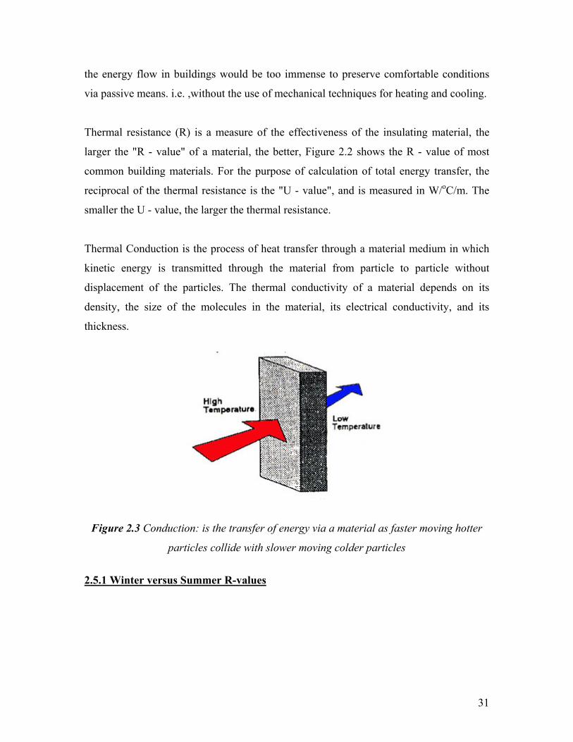
Thermal Conduction is the process of heat transfer through a material medium in which
kinetic energy is transmitted through the material from particle to particle without
displacement of the particles. The thermal conductivity of a material depends on its
density, the size of the molecules in the material, its electrical conductivity, and its
thickness.
Figure 2.3 Conduction: is the transfer of energy via a material as faster moving hotter
particles collide with slower moving colder particles
2.5.1 Winter versus Summer R-values
31

Figure 2.4 Winter versus summer R values
(Image from http://www.energy.wa.gov.au)
The difference in R-values are quoted for the same materials in summer and in winter.
This is because the total heat transfer depends on whether the energy is flowing into or
out of the building. In summer, when it is hotter outside than inside, highly reflective
surfaces, such as foil, aluminium paint and light coloured roofing materials will help to
reduce the radiant heat gains. In winter, when the inside of the house is warmer,
reflecting surfaces on or underneath the roof will do little to prevent energy from being
transferred through the ceiling. Any warm air on top of the ceiling is free to escape, and
will not provide the same insulating air film thickness as in summer.
32

Chapter 3: Passive Renewable Technologies
The roles of energy efficiency and energy conservation find the notion that once these
issues have been addressed, energy consumption can be further reduced by making use of
the available renewable resources that can be applied passively, i.e. by non-mechanical
means.
3.1 Building Design
Energy has different grades: the higher the grade, the higher the energy's environmental
impact. The key to minimizing the impact of buildings on the environment is to match the
right level of energy grade with the needs of the user. Low-grade tasks, such as heating
rooms, should be matched with low-grade energy sources like passive solar gain.
Natural daylight, restricting electrical lighting to night- time use, and natural ventilation
are just some of the solutions for low-energy building design. Ensuring a building's
facade and mechanical systems work together to reduce energy emissions is a key
element in achieving the right balance of heat loss and gain.
Low-energy solutions do not mean high costs; they are often cheaper to commission,
maintain, and install than other options. A combined approach of conventional design
with alternative energy sources not only creates a comfortable environment for building
users, but it can make considerable savings as well.
The impact of solar radiation causes changes in the earth’s temperature. As the earth
possesses vast heat storing capacity, it takes a long time for it to cool down after sunset,
as well as longer time for the temperature to increase after the sun rise. As a result of this
phenomenon, higher temperatures are available in the afternoons than mornings although
the amount of solar radiation at both times are similar.
33

Therefore, the design of buildings should be based on a similar concept, in that buildings
should be designed to achieve a steady state thermal condition without variations due to
changes in the external climate conditions. This procedure involves the integration of
thick walls which store heat during the day, preventing the seepage of heat into the
interior of the building. During the night, when there is no sunshine, heat stored by the
thick walls will be dissipated into the building. In order to achieve thermal comfort by
occupants in a building, it is necessary for them to lose amounts of heat which are
proportional to the amount generated by physical activities.23
3.2 Passive Renewable Energy use in Buildings
Passive solar designs include passive solar heating, cooling, day lighting and natural
ventilation.
3.2.1 Passive Solar Energy
The history of making the best use of sunlight through passive techniques dates back to
the Romans, where passive techniques were used for spaces such as communal meeting
places and the bath house. Such places were designed with large window openings. After
the fall of the Roman Empire, the ability to produce large sheets of glass disappeared for
at least a millennium. It was not until the end of the seventeenth century that the glass
process reappeared in France.
In the eighteenth and nineteenth centuries cities were over crowded and most buildings,
including houses were poorly lit. It was not until the late nineteenth century that urban
planners investigated the potential of providing better internal conditions. At this time the
planners were more concerned about the medical advantages of sunlight after discovering
that ultraviolet light kills bacteria. A later realization that ultraviolet light does not
penetrate windows, did not change this new-found tradition of allowing access for
sunlight into the houses, and this was reinforced by findings that bright light in winter is
34

essential to maintain human hormone balances. Without it people are more likely to
develop midwinter depression.16
3.2.2 Passive Solar Heating
3.2.2.1 General
In the winter, south facing windows are expected to provide access for the sun’s heat
while on the other hand insulation against the cold is also necessary. In the summer, in a
moderate climate the policy is to admit the sun light and to store the heat. Since most of
the day lighting, heating and cooling facilities are on the southern part of the building that
is where most of the interior spaces are located.
When designing buildings for passive solar renewable energy, they should incorporate
features such as large amounts of windows facing south, to allow maximum solar access.
In addition building materials that absorb and gradually release the heat absorbed by the
sun should be used in combination with south facing glazing.2
An important concept of passive solar design is to match the time when the sun can
provide day lighting and heat to a building with those when the building needs heat, this
is fairly easy to achieve in domestic buildings, but when it comes to commercial
buildings, there are complex demands for heating, cooling, and lighting; therefore their
design strategies require computer analysis (e.g. by an energy modeling tool such as ESP-
r) by an architect or an engineer.18
Design strategy plays an important role, and a building’s floor plans should be designed
to optimize passive solar heating. For example appropriate glazing in windows and doors,
and orientated within 30 degrees of true south.
35

Figure 3.1 Design strategy: windows and doors should be orientated within 30 degrees
of true south
(Image from http://www.esru.strath.ac.uk )
Because of the solar path, the optimum orientation for direct gain in passive solar
buildings is due south. South-facing surfaces do not have to be all along the same wall.
For example, clerestory windows can project south sun deep into the back of the building.
Both the efficiency of the system and the ability to control shading and summer
overheating decline as the surface shifts away from due south.2
The basic requirements to optimize the use of passive solar heating in buildings are as
follows:
• Buildings should face south with the main orientation of the building within 30o,
buildings located South East will take more advantage of the morning sun, while
those located on the South West will benefit more from the late afternoon sun
delaying the evening heating period.
• The glazing should be concentrated on the south-side as they are most frequently
used and require most heating, so as the living rooms, with little used rooms such
as bathrooms on the north
• Responsive zoned heating systems facilitate automatic isolation of areas when and
where necessary, thus avoiding the unnecessary heating of unoccupied rooms
• Avoid over shading by other buildings in order to benefit from the mid-winter sun
• Buildings should be thermally massive to avoid overheating in the summer
36
• The windows should be large enough to provide enough day lighting minimum
15% of a room’s floor area (Dept of Environment – Best Practice Programme)
• Buildings should be well insulated to minimize the overall heat loss
3.3 Direct and Indirect Gain Systems
Heating systems are generally classified into two categories, direct and indirect gain
systems. Direct gain system utilize collectors to allow light directly into the house, where
it is absorbed and converted into heat. Indirect gain systems create intermediate spaces,
external to the house, where light is converted to heat, and then the heat is exchanged
with the house via intermediate elements. Roof ponds, greenhouses, and trombe walls are
all examples of this technique.18
However it should be noted that overheating and glare can occur whenever sunlight
penetrates directly into a building and this must be addressed through appropriate
measures. A "direct-gain" space can overheat in full sunlight and is many times brighter
than is required for ‘normal’ indoor lighting, this can result in glare problems. In late
morning and early afternoon, the sun enters through south-facing windows. The low
angle allows the sunlight to penetrate deep into the building beyond the normal direct-
gain area. If the building and occupied spaces are not designed to control the impact of
the sun's penetration, the occupants will experience discomfort from glare. Careful sun-
angle analysis and design strategies will ensure that these low sun angles are addressed.
For example, light shelves can intercept the sun and diffuse the daylight.2
3.3.1 Direct Gain
Direct gain is the simplest approach and usually the most economical to build. Using this
technique sunlight enters the building through large areas of south facing glass, it heats
the floor and walls directly.
37

Figure 3.2 Direct gain solar system
(Image from www.ncsc.ncsu.edu)
Clerestory windows and skylights are used to increase the amount of sunlight hitting the
back area of walls or floors. They can improve the performance of the direct gain system,
usually skylights tend to create overheating in the summer and in a climate such as the
UK’s these may leak if improperly installed or if not well insulated.
Figure 3.3 Clerestory windows in a direct gain system let sunlight strike thermal mass
on the back wall.
(Image from www.ncsc.ncsu.edu)
38

Figure 3.4 The overhang allows in the winter sun while shading the south facing glass in
the summer
(Image from www.ncsc.ncsu.edu)
In direct gain systems, the amount of south facing glass and thermal storage mass should
be balanced for optimum summer, winter and mid season performance. If the windows
collect more heat than the floor or walls can absorb, overheating occurs. Therefore
shading is required to minimize the heat gain in the summer. There are several choices
such as overhangs, awnings, trellises, louvers, solar screens and movable insulation.
Nowadays exterior shading is more recommended rather than interior shading because
exterior screens and other devices will stop heat before it gets into the building.
In addition, attention to the location and quantity of fabric mass should be made. For
example the thermal storage maybe thinner and more widely distributed in the living area
than with other passive systems. Covering the thermal storage mass with carpet or other
materials will reduce its storage capacity, therefore arranging furnishings is important so
as not to interfere with the solar collection, storage and distribution. The table below
compares the advantages and disadvantages of various direct gain systems:
Advantages Disadvantages
South facing windows provide natural day
lighting and outdoor views
Large amounts of south facing glass can
cause problems with glare and privacy
It provides direct heating. There is no need
to transfer energy from one area to another
The thermal mass used for heat storage
should not be covered by carpet or blocked
by furnishings
The number and size of south facing
windows can be adjusted to match the
space for thermal mass. Clerestory
windows can let sunlight fall directly on
the back parts of floors or walls used as
thermal mass
It can overheat if the windows and thermal
mass are not balanced
39

It is comparatively low in cost to build,
since no special room has to be added. The
floor, walls, can serve as the storage mass.
The solar elements are incorporated into
the occupied/living space.
South facing windows need summer
shading and a night time isolative covering
in winter. Night time insulation can be
provided by exterior mounted panels,
interior draperies, shutters, pop in panels,
or other insulating window treatments
Furnishings and fabrics exposed to
ultraviolet radiation from the sun can
degrade or change color.
Table 3.1 Advantages and Disadvantages of Direct gain Systems
Figure 3.5 Louvered panels provide shading if the overhang is insufficient
(Image from www.ncsc.ncsu.edu)
3.3.2 Indirect Gain
In this method the storage mass is located between the south facing glass and the living
space. Indirect gain systems use systems such as thermal walls and other types of
materials to store collected heat. The common ways of storing mass are a masonry
Trombe wall, a water wall of tubes or barrels located several millimeters behind the
window.
The brick trombe wall is usually 200-300mm in thickness when compared with direct
gain which is usually 100-150mm thick but it is spread out over a larger area. As the
sunlight passes via the south facing glass, it is absorbed by the mass of the wall. The wall
40

heats up gradually and releases the heat to the living areas anything from 6 to 8hours
later. The time lag between the warming of the mass and releasing of the heat helps to
keep temperatures in the living area steady, therefore heating is available in the late
afternoon and evening when it is most needed. In a domestic situation this is most useful
when the house is unoccupied during the day but occupied at night.
Figure 3.6 Trombe wall vents circulate heated air to the living area in the day time,
meanwhile at night the vents are closed to prevent reverse cycling of heated air.
(Image from www.ncsc.ncsu.edu)
The Trombe walls can be vented or un-vented. The vented wall allows heated air to
circulate directly to the living area. A vented trombe wall requires night time closing of
wall vents, because if not closed the heated air would cycle back to the front of the
trombe wall from the living area. Trombe walls have been used less frequently in recent
years because of the difficulty in ensuring the proper opening and closing of vents.
Research indicates that trombe walls gain more heat during the night. Therefore
moveable insulation over the trombe wall will improve its efficiency. The table below
lists the advantages and disadvantages of indirect gain systems:
Advantages Disadvantages
The storage mass is positioned closer to the
glass or collection area, which allows for
efficient collection of solar energy.
The south facing view and natural daylight
is lost. Some trombe walls have been
designed with windows set into the wall to
compensate.
41

The floor and wall space of the living area
can be used more flexibly since the storage
mass is moved next to the south facing
glass. This frees the interior space and does
not expose furnishings to direct sunlight.
The trombe wall may take up too much
wall space in a smaller building.
The thickness and heat storage capacity of
the thermal mass heats up gradually and
distributes the heat to the living area when
it is most required.
Furniture and objects placed against or on
the trombe wall affect the efficiency of the
trombe wall heating the living area.
Because the trombe wall heats only the
area it is connected to, the cost of labor and
materials in its construction may be high
relative to the contribution it makes to the
overall heating needs of the building.
Vented trombe walls must be closed at
night to prevent reverse cycling of heated
air.
In the summer or on winter days without
sunshine, the trombe wall acts as a very
poorly insulated wall. Exterior moveable
insulation would improve its effect on
comfort and energy use.
Table 3.2 Advantages and Disadvantages of Indirect gain Systems
The following case studies highlight the use of passive solar energy for heating and
daylighting in schools.
3.3.3 Case Studies
3.3.3.a The Wallasey School Case Study
42

The Wallasey school in Cheshire was constructed in 1961, and the design was stimulated
by earlier US and French buildings. The Wallasey school building has the basic features
required for passive solar heating and daylighting and it is thus considered as a direct
gain design. Some of the features of the school are:
• Thermally heavy weight construction (dense concrete or brickwork). This stores
the thermal energy through the day and into the night;
• A large area of south facing glazing to capture the sunlight;
• Thick insulation on the outside of the structure to retain the heat
Figure 3.7 The Wallasey School in Cheshire, UK
(Image from Godfrey Boyle, Renewable Energy; Power for a Sustainable Future)
Figure 3.8 Cross-section of the Wallasey School
43
(Image from Godfrey Boyle, Renewable Energy; Power for a Sustainable Future)
After the construction of the school building, it was found that the oil fired heating
system was later found to be unnecessary and was removed. Therefore the building was
totally heated by a combination of solar energy, light, heat gains from equipment and
occupancy of students.16
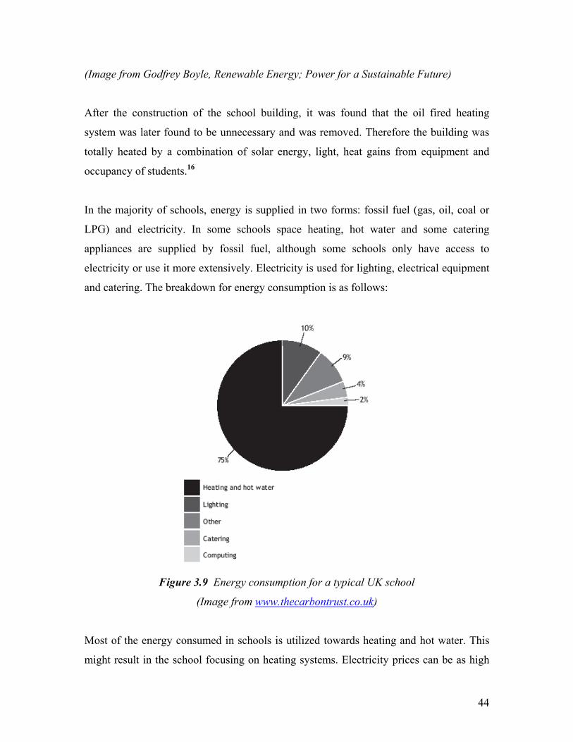
In the majority of schools, energy is supplied in two forms: fossil fuel (gas, oil, coal or
LPG) and electricity. In some schools space heating, hot water and some catering
appliances are supplied by fossil fuel, although some schools only have access to
electricity or use it more extensively. Electricity is used for lighting, electrical equipment
and catering. The breakdown for energy consumption is as follows:
Figure 3.9 Energy consumption for a typical UK school
(Image from www.thecarbontrust.co.uk)
Most of the energy consumed in schools is utilized towards heating and hot water. This
might result in the school focusing on heating systems. Electricity prices can be as high
44

as 6p/kWh whereas fossil fuel maybe as low as 1p/kWh. Upto 80% of energy consumed
in schools is from fossil fuels and this accounts for 40% of the cost. The diagram below
shows the cost breakdown for energy use in a typical school. Lighting accounts for
almost 50% of electricity costs, with electrical equipment, catering, fans and pumps
making up the rest.
Figure 3.10 Energy cost for a typical UK school
Benchmarking allows schools to compare their energy performance with other schools.
Most schools are interested in knowing the potential for saving energy and water.
Benchmarks are calculated separately for fossil fuel and electricity so that a school can
determine performance for each type of energy use. The range of benchmarks available is
helpful in determining realistic quantified potential savings. In schools the benchmark is
measured in kilowatt/hour (kWh) per m2 of heated floor space per annum for fossil fuel
and electricity. The table below shows the energy benchmarks for a good, typical and
poor performing schools.
45

Table 3.3 Energy benchmarks for a good, typical and poor performing schools
(Table from Good Practice Guide 057)
The calculation of carbon dioxide CO2 emissions is possible through the factors available
at the table below:
Table 3.4 CO2 emissions by fuel type for UK
(Table from Good Practice Guide 057)
To calculate a school’s carbon dioxide emissions, it is required to multiply the
consumption in (kWh) by the CO2 factor available in table 3.4.
46

Table 3.5 Calculation of CO2 emissions
(Table from Good Practice Guide 057)
3.3.3.b The Pennyland Case Study
The Pennyland estate in Milton Keynes in central England was built in the late 1970s.
The design layout is shown in the diagrams below:
Figure 3.11 Passive solar housing at Pennyland. The view of the south elevation showing
the main living rooms having large windows.
(Image from Godfrey Boyle, Renewable Energy; Power for a Sustainable Future)
Figure 3.12 The view at the northern side of the buildings has smaller windows.
(Image from Godfrey Boyle, Renewable Energy; Power for a Sustainable Future)
47

Figure 3.13 Plans for the solar housing at Pennyland
(Image from Godfrey Boyle, Renewable Energy; Power for a Sustainable Future)
An entire estate of these houses was built and they have been monitored since. It is found
that the steps (1-5) listed in the diagram below produced houses that consumed almost
50% less gas than that consumed by a normal house built in the previous year, although
the extra cost was 2.5% of the overall construction cost but the payback time was four
years.
Figure 3.14 Design steps in low energy housing
(Image from Godfrey Boyle, Renewable Energy; Power for a Sustainable Future)
48

When differentiating between the broad and narrow definitions of passive solar heating, it
includes all energy saving techniques listed in the steps (1-5). In the narrow sense it
covers the parts that are rigidly solar based (3-5).
By applying points (3-5) it helped save more than 500kWh per year on space heating
energy. The 500kWh is the difference in energy consumption between a solar and a non-
solar house having the same standard of insulation.16 Meanwhile situated in a low
mountain valley, the Wates house is not well located to make use of passive solar
heating, but it was intended to be heated and lit by electricity from a wind turbine.
3.4 Passive Solar Cooling
Before the advent of refrigeration technology, people kept cool in buildings by using
natural methods e.g.:
• Breezes flowing through windows
• Water evaporating from springs and fountains
• Large amounts of stone and earth to absorb daytime heat.
These ideas were developed over thousands of years as integral parts of building design.
Ironically passive cooling is now considered an "alternative" to mechanical cooling that
requires complicated refrigeration systems. By employing passive cooling techniques into
modern buildings, it is possible to eliminate mechanical cooling or air conditioning or at
least to reduce the size and cost of the equipment.18 Cooling by whatever means is merely
the opposite of heating. As such, it involves controlled selected rejection of the incident
energy by the collecting apertures. Thermal storage is minimized by heat transfer
between storage elements and the ambient heat sinks in the building, such as windows
providing ventilation.2
Passive cooling techniques can be used to minimize, and in some cases eliminate,
mechanical air conditioning requirements in areas where cooling is a dominant problem.
49

In many cases in modern buildings with high internal gains, thermal comfort in summer
means more than simply keeping the indoor air temperature below 24°C, comfort is
related mainly to a balance of temperature and humidity.18
There are several passive cooling strategies, and they are as follows :
3.4.1 Natural Ventilation
This technique depends mainly on air movement to cool occupants. Window openings on
opposite sides of the building enhance cross ventilation driven by breezes. Since natural
breezes can not be scheduled, designers often choose to enhance natural ventilation using
tall spaces within buildings called stacks or chimneys.
With openings near the top of the stack, warm air can escape, while cooler air enters the
building from openings near the ground. Ventilation requires the building to be open
during the day to allow air flow.
3.4.2 High Thermal Mass
This technique relies on the ability of materials in the building to absorb heat during the
day. Each night the mass releases heat, making it ready to absorb heat again the next day.
To be efficient, thermal mass must be exposed to the living spaces. Residential buildings
are considered to have average mass when the exposed mass area is equal to the floor
area. A slab floor would be an easy way to achieve this in a design. High mass buildings
would have up to three square feet of exposed mass for each square foot of floor area.
Large masonry fireplaces and interior brick walls are two ways to incorporate high mass.
50

3.4.3 High Thermal Mass with Night Ventilation
This technique depends on the daily heat storage of thermal mass combined with night
ventilation that cools the mass. The building must be closed during the day and opened at
night to flush the heat away.
3.4.4 Evaporative Cooling
Evaporative cooling decreases the indoor air temperature by evaporating water. In dry
climates, this is commonly done directly in the space. But indirect methods, such as roof
ponds, allow evaporative cooling to be used in more temperate climates too.
Ventilation and evaporative cooling are often supplemented with mechanical means, such
as fans. They use considerably less energy to maintain comfort compared to refrigeration
systems. It is also possible to use these strategies in completely passive systems that
require no additional machinery or energy to operate.
The following case study demonstrates both the passive cooling methods and daylighting
techniques being adopted at De Montfort University.
3.4.5 Case Studies
3.4.5.1 The Queens Building, De Montfort University Case Study
In 1989 the building stock of De Montfort University’s city campus (formerly Leicester
Polytechnic) was judged as Inoperable and Unsafe. It was therefore decided to construct a
new building for the School of Engineering and Manufacture. The building was named
51

the Queens Building and it provides academic facilities to 1500 students in the School of
Engineering and Manufacture.
Figure 3.15 Side view of the De Montfort University city campus
(Image from New Practice Case Study 102)
The construction of the building makes visible the structural, acoustic and ventilation
techniques employed. The 10,000m2 structure has three distinctive elements and they are
as follows:
Figure 3.16 The natural ventilation strategy in the central building
52
(Image from New Practice Case Study 102)
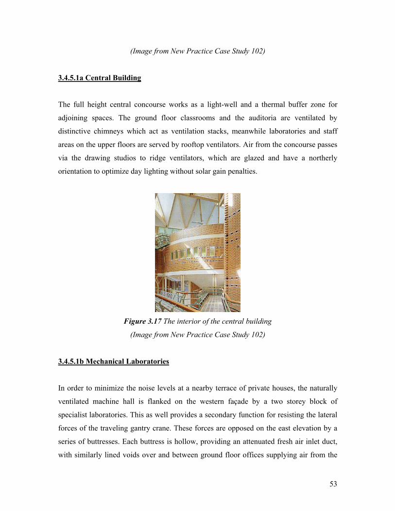
3.4.5.1a Central Building
The full height central concourse works as a light-well and a thermal buffer zone for
adjoining spaces. The ground floor classrooms and the auditoria are ventilated by
distinctive chimneys which act as ventilation stacks, meanwhile laboratories and staff
areas on the upper floors are served by rooftop ventilators. Air from the concourse passes
via the drawing studios to ridge ventilators, which are glazed and have a northerly
orientation to optimize day lighting without solar gain penalties.
Figure 3.17 The interior of the central building
(Image from New Practice Case Study 102)
3.4.5.1b Mechanical Laboratories
In order to minimize the noise levels at a nearby terrace of private houses, the naturally
ventilated machine hall is flanked on the western façade by a two storey block of
specialist laboratories. This as well provides a secondary function for resisting the lateral
forces of the traveling gantry crane. These forces are opposed on the east elevation by a
series of buttresses. Each buttress is hollow, providing an attenuated fresh air inlet duct,
with similarly lined voids over and between ground floor offices supplying air from the
53

west façade. The glazed ridge vents, and the west facing gable windows, which are triple
glazed to reduce noise penetration to the outside, ensuring that the machine hall is well
day lit.
Figure 3.18 Section through the mechanical laboratories
(Image from New Practice Case Study 102)
3.4.5.1c Electrical Laboratories
The electrical laboratories are housed in two shallow plan, four storey wings, and so they
benefit from cross ventilation and well distributed day lighting. Low-level and high-level
opening windows are large enough to provide sufficient ventilation to dissipate the high
internal gains from equipment, meanwhile the cantilevered façade minimizes direct solar
gain and glare.
54
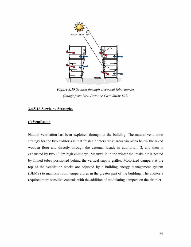
Figure 3.19 Section through electrical laboratories
(Image from New Practice Case Study 102)
3.4.5.1d Servicing Strategies
(i) Ventilation
Natural ventilation has been exploited throughout the building. The natural ventilation
strategy for the two auditoria is that fresh air enters these areas via plena below the raked
wooden floor and directly through the external façade in auditorium 2, and then is
exhausted by two 13.3m high chimneys. Meanwhile in the winter the intake air is heated
by finned tubes positioned behind the vertical supply grilles. Motorized dampers at the
top of the ventilation stacks are adjusted by a building energy management system
(BEMS) to maintain room temperatures in the greater part of the building. The auditoria
required more sensitive controls with the addition of modulating dampers on the air inlet.
55

Figure 3.20 Air enters the auditorium via plena under the raked seating
(Image from New Practice Case Study 102)
The basic requirement when are the auditoria are occupied is for a minimal supply of
fresh air, as determined by carbon dioxide (CO2) sensors, with an increasing air volume
to meet the cooling load, provided that the internal temperature exceeds the external
temperature. To avoid draughts, the fresh air is heated to a minimum temperature, and
stack dampers will close if the temperature in the middle of the stack is sensed to be less
than 12oC. Sensors also prevent dampers from opening to more than 50% if there is a risk
of entry of wind driven rain.
(ii) Day lighting
Spaces are lit primarily from side windows, which are shaded from direct solar heat gain
by deep reveals, overhanging eaves or adjacent parts of the building. A number of small
windows is used to provide well distributed daylighting without the penalties of high heat
transfer. North lights and roof lights are used extensively to meet the combined needs of
stack ventilation and daylighting, while the full height concourse admits daylight into the
core of the main building.
56

3.4.5.2 Building Services
3.4.5.2a Space Heating and Domestic Hot Water
The main heating plant consists of a small 38kWe combined heat and power (CHP) unit,
a condensing boiler and two high efficiency boilers, sequenced to fire in that order,
provided there is sufficient demand for electricity and heating.
3.4.5.2b Electric Lighting
High efficiency lamps such as compact and T8 linear fluorescents, and high-pressure
discharge sources are used to supplement daylighting. During normal working hours,
lighting circuit contactors are energized by the BEMS and then controlled locally via
manual switches. At other times the BEMS switches off circuits in unoccupied spaces via
passive infrared detectors (PIRs).
3.4.5.2c Building Energy Management System (BEMS)
The BEMS controls the heating, lighting and ventilation systems, averaging thermostats
in the ten different control zones are ‘set back’ to allow night time cooling in the summer.
Numerous additional sensors have been added to the BEMS so as to be used for
educational purposes.
3.4.5.2d Energy Use
Energy consumption for the first year of operation based on gross floor area, equated to
114kWh/m2 for gas and 43kWh/m2 for electricity with a corresponding CO2 emission of
53kg/m2. The avoidance of mechanical ventilation resulted in a significant reduction in
use of electricity, although the electric lighting demand could well be lower if the
automatic controls were fully operational.
57

Figure 3.21 Annual energy consumption compared to DOE’s low and high yardsticks
(Image from New Practice Case Study 102)
Although after two years of operation yet there were still outstanding adjustments to be
made. The CO2 detectors are reported not to be functioning properly. Delayed energizing
of lighting circuits by the occupancy sensors have resulted in this mode of control being
largely overridden. The PIR detectors are thought to be insufficiently sensitive, and
feeding their signals back through the BEMS imparts a noticeable delay.
Figure 3.22 Annual CO2 emissions compared to DOE’s low and high yardsticks
(Image from New Practice Case Study 102)
58

Meanwhile in the mechanical laboratories, the objective was to replace electric lighting
with natural daylighting, but it happens to be unpractical because electric lighting is used
whenever heavy machinery is operating on health and safety grounds.
3.4.5.2e Costs
The construction process of the queens building proved to be no more costly (at £855/m²)
than a more conventional building. This was a fundamental requirement of the
Polytechnic and Colleges Funding Council, because it had to fall within the established
cost criteria. The diagram below shows the comparison in costs between a normal
engineering building and the queens building.
Figure 3.23 Comparison in costs
(Image from New Practice Case Study 102)
The passive approach being adopted at the Queens building happens to have provided an
acceptable internal environment during its early operation. The problem areas being the
59

result of very conventional openers not being installed. The queens building demonstrates
an advance in the ‘greening’ of both buildings and urban redevelopment.
The building has shown that adopting such a low energy design approach did not conflict
with the functional aspects of the facility and has resulted in landmark at no additional
costs. The Queens Building is a testimony to what can be achieved in terms of low
energy design.
3.5 Day lighting
In most commercial office buildings, lighting can account for up to 30% of the delivered
energy use. With the introduction of cheap electricity, in the 19th century natural
daylighting was gradually disregarded and most modern office buildings depend
primarily on electric lighting.
Figure 3.24 Mirrors were used to capture daylight in narrow streets in London before
World War II
(Image from Godfrey Boyle, Renewable Energy; Power for a Sustainable Future)
However if properly designed and efficiently integrated with the electric lighting system,
daylighting can offer considerable energy savings by offsetting a portion of the electric
lighting load up to 25%. A related benefit is the reduction in cooling capacity and use by
60

lowering a significant component of internal gains. In addition to energy savings, day
lighting generally improves occupant satisfaction and comfort.16
3.5.1 The Stansted Airport Terminal Case Study
Stansted airport is considered one of the most well day lit airports in the world, and also
one of the most sustainable designs. Stansted airport is London’s third airport, and was
completed in 1991 to provide additional air services in the south of England. The
construction is mainly comprised of steel, concrete and glass. The main structural
elements are painted light grey and the other surfaces are finished in white and the floor
is polished grey and white speckled granite.3
Figure 3.25 Cross-section through Stansted Airport
(Image from BRE)
The perimeter of the building, specifically in the entrance and the main public circulation
areas, are glazed from the floor level to the underside of the roof structure. In the main
entrance area which faces approximately south east, the glass is entirely clear, whereas in
the circulation areas there are bands of translucent glass to diffuse direct sunlight, thus
reducing direct gain.
61
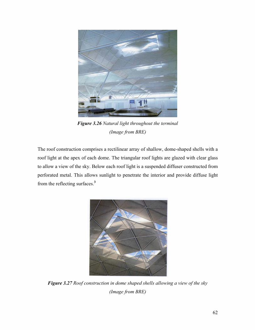
Figure 3.26 Natural light throughout the terminal
(Image from BRE)
The roof construction comprises a rectilinear array of shallow, dome-shaped shells with a
roof light at the apex of each dome. The triangular roof lights are glazed with clear glass
to allow a view of the sky. Below each roof light is a suspended diffuser constructed from
perforated metal. This allows sunlight to penetrate the interior and provide diffuse light
from the reflecting surfaces.3
Figure 3.27 Roof construction in dome shaped shells allowing a view of the sky
(Image from BRE)
62

At the main entry point there is an external canopy formed from the continuation of the
roof shells, which provide shade at the passenger drop-off and pick up point. The light
pattern and intensity vary according to movement through the building. Natural sunlight
is evident throughout the concourse. As well as falling in small patches below each roof
light, the daylight reflects to give an overall sense of natural light. Daylight levels are
higher at the edges of the building, therefore the resulting effect is one of the visual
lightness and on sunny days dappled sunlight provides variety in the light pattern on the
floor of the terminal. The dominant impression is of calm efficiency and on bright days
this is largely a day lit building for much of the time with no demand for electrical
lighting.3
Day lighting is a combination of energy conservation and passive solar design. The
objective is to make the most benefit from the sunlight. Some other techniques are:
• Roof lights
• Windows with large dimensions allowing sunlight to penetrate inside rooms
• The use of task lighting directly over the workplace, instead of lighting the
whole interior of the building
• Shallow plan design, allowing daylight to penetrate rooms and corridors
• Light wells in the centre of the building.3
3.5.1.1 The Technology
Daylighting is the efficient use of natural light in order to minimise the need for artificial
light in buildings. Daylighting is achieved by control strategies and adapted components
which fall mainly into three categories:
• Conduction components - spaces used to guide or distribute light towards the
interior of a building
• Pass-through components (e.g. windows) - these allow light to pass from one
room or section of a building to another
63

• Control elements - specially designed to control the way in which light enters
through a pass-through component.4
The status of these strategies/components are as follows:
• Commercially available: skylights and roof lights; clerestories; automatic controls
for blinds and traditional shades; high reflectance paint to improve cavity optics
• In the market: spectrally selective glazing or films; atria
• Development/demonstration: prismatic glazing; tracking light collectors; light
pipes and ducts; optical control systems; light shelves and reflectors
• Research: holographic films; chromogenic glasses; electro chromic and
directionally transmitting glazing; optical fibres.
The competitive situation in this market is difficult to assess. The major cost element of
daylighting design lies in expertise rather than manufactured goods whose real prices are
unknown because so many products are still under development.2
3.5.1.1a Technical Barriers
The main factors hindering the implementation of daylighting in commercial buildings
are:
• lack of information - architects, decision makers and the public tend to be
ignorant of the possible benefits of daylighting design; relative efficiencies of
different types of scheme are largely un-researched and few studies of the
economic aspects are available
• lack of industrial lobbying - there is a strong industrial lobby in favour of artificial
lighting from electric utilities and international manufacturers, which has no pro-
daylighting equivalent
• lack of legislation to encourage its use - there are few regulations or even codes of
practice in place to ensure that daylighting is given due consideration in new
design.2
64

3.5.1.1b Market Barriers
Information on products or daylighting design strategies are requested at a very early
stage in the designing process. Architects should receive extra training and information
packages on these aspects. But as no industrial lobbying exists to promote such passive
options, it is dubious it will appear without strong public or State involvement.
Information on daylighting is scarce and few economic studies are available.
Ignorance among decision makers, architects and public about benefits and performance
of daylighting design leads to reluctance to try the technology which affects the take up
rate. Meanwhile there is no particular technical risk is perceived (as there is always a
"backup" solution with already installed artificial lighting) but daylighting advantages are
not perceived either.4
In commercial buildings which are the most interesting market for daylighting, people in
charge of investment are rarely those who occupy and manage the building later, they do
not benefit from the electricity savings. There is no particular environmental concern that
constitutes a barrier to uptake of daylighting design. All passive solar strategies and
techniques benefit from positive environmental advantages which should help their future
implementation.
3.5.1.1c Financial barriers
The additional costs of passive solar features included in cost calculations vary from zero
to 20% and some features such as sunspaces or larger glazed areas are often included as
much for their amenity value as for the potential energy savings, so their full costs should
not really be included in the calculations.
No particular financial barrier for daylighting solutions exists within private commercial
buildings. For State owned buildings, accounting rules do not allow for paying off extra
investment costs on subsequent savings.4
65

3.5.1.1d Price distortions
Commercial buildings can benefit from very low electricity tariffs in summer and mid-
season periods which do not induce reducing lighting (neither cooling loads).
3.5.1.1e Regulations
Most existing codes and standards do not take lighting and even less daylighting into
account. It is only health codes in working places (labour regulation) that indicate the
need for quality lighting, suggesting some daylighting options. Enforcement of these
texts is not fashionable even though regulation is one of the most effective policy
instruments for energy conservation.
3.5.1.1f Other non technical issues
Development of passive solar products: although all the savings outlined above may be
made using existing technology, there is considerable potential for even greater savings
as new generation products are developed and made widely available like transparent
insulation or smart glazing.3
Poor lighting can be a major - but often unrecognised - cause of worker dissatisfaction
and inefficiency. It can cause workers to make more mistakes or be less productive. Their
health can even be affected. It is often forgotten that employees are the major asset and
expense of a company: the annual lighting costs per person in an average office can be
equivalent to only three to four hours salary. Thus if staff are de-motivated or visually
impaired through inadequate working conditions, their productivity will deteriorate.
3.6 Summary
This chapter overviewed passive renewable technologies with case studies provided to
highlight the advantages of each technology. In the Wallasey School case study passive
solar heating and daylighting strategy is being adopted. It is clear from the design of the
building which was inspired by US and French buildings. The school gains its heat
66

through a combination of internal gains ranging from students and equipments to solar
energy and daylighting.
Meanwhile the Pennyland case study indicates the importance of insulation and in the
design stage to locate large windows facing south in an attempt to gain more sunlight. In
this chapter natural ventilation strategies are also being discussed and the Queens
Building case study shows the effectiveness of natural ventilation throughout the
building. Although the building was declared inoperable and unsafe in 1989. Hence a
new building was constructed and named the Queens Building.
The building was ventilated by distinctive chimneys which act as ventilation stacks.
Meanwhile in the winter the intake air is heated by finned tubes located behind the
vertical supply grilles. On the other hand when it comes to natural daylighting, the
Stansted airport terminal proves as a good example of sustainable building design as the
dome shaped shells are distinctive in shape and are designed in such a way to gain and
utilise the most of sun lighting.
67

Chapter 4: Integrated ‘Active’ Renewables & Novel Systems
As discussed in chapter one new buildings offer more options for energy efficiency and
new renewable systems being built or installed during the construction stage of the
building itself. These systems may involve building materials integrated in the
construction or technologies such as local small scale generation such as PV, solar water
heating, ducted wind turbines (DWT) and CHP.
4.1 Small Scale Integrated Renewable Technologies
The types of small scale integrated renewable technology appropriate for integration in
commercial buildings are discussed in the following sections:
4.1.1 Solar Photovoltaics
Photovoltaic (PV) cells are made of semiconductor materials such as silicon, which is the
most commonly used material. When light strikes the material (solar cell), a certain
portion of it is absorbed within the cell material. The energy of the absorbed light
(photons) is transferred to the semiconductor. This energy knocks electrons loose,
allowing them to flow freely. This flow of electrons creates an electrical current, and by
placing metal contacts on the top and bottom of the PV cell, this current can be drawn off
to use externally to charge a battery, power a device or a, building.
Photovoltaic cells can be utilized individually for small applications, however more
power is needed a number of cells are put together to form a module, and modules can
also be grouped together to form arrays. In theory arrays can range from a small number
of modules to power a building to thousands of modules to power a town.
68

Figure 4.1 Cells combined to form modules and then onto arrays
PV is a flexible building material. It can be used for roofs, curtain walls, decorative
screens can be embedded in glazing, and can also directly replace other conventional
materials in the building fabric. These products can serve the same structural and weather
protection purposes as their traditional alternatives, as well as offering the benefit of
power generation. PV generates approximately 100 kWh/m2 depending on the type of PV
and system efficiency.
There are several different types of PV panel:
• Monocrystalline PV – this is a single crystal structure and is the simplest type of
PV;
69
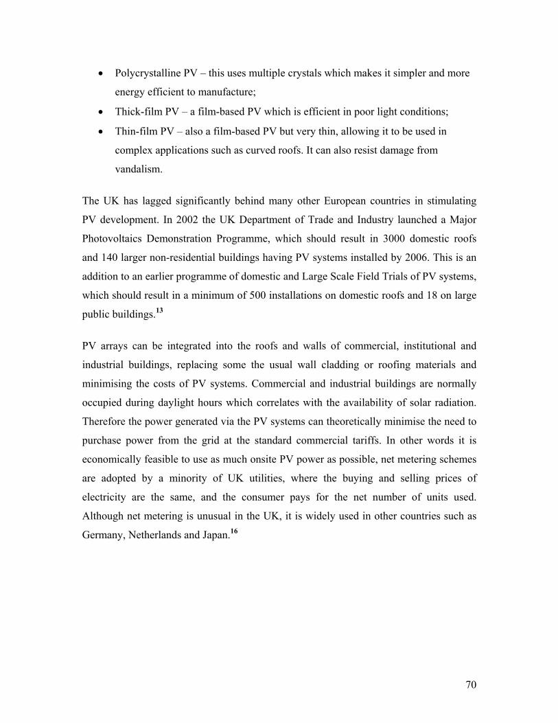
• Polycrystalline PV – this uses multiple crystals which makes it simpler and more
energy efficient to manufacture;
• Thick-film PV – a film-based PV which is efficient in poor light conditions;
• Thin-film PV – also a film-based PV but very thin, allowing it to be used in
complex applications such as curved roofs. It can also resist damage from
vandalism.
The UK has lagged significantly behind many other European countries in stimulating
PV development. In 2002 the UK Department of Trade and Industry launched a Major
Photovoltaics Demonstration Programme, which should result in 3000 domestic roofs
and 140 larger non-residential buildings having PV systems installed by 2006. This is an
addition to an earlier programme of domestic and Large Scale Field Trials of PV systems,
which should result in a minimum of 500 installations on domestic roofs and 18 on large
public buildings.13
PV arrays can be integrated into the roofs and walls of commercial, institutional and
industrial buildings, replacing some the usual wall cladding or roofing materials and
minimising the costs of PV systems. Commercial and industrial buildings are normally
occupied during daylight hours which correlates with the availability of solar radiation.
Therefore the power generated via the PV systems can theoretically minimise the need to
purchase power from the grid at the standard commercial tariffs. In other words it is
economically feasible to use as much onsite PV power as possible, net metering schemes
are adopted by a minority of UK utilities, where the buying and selling prices of
electricity are the same, and the consumer pays for the net number of units used.
Although net metering is unusual in the UK, it is widely used in other countries such as
Germany, Netherlands and Japan.16
70

Figure 4.2 Britain’s first building with PV cladding, a 40kWp system installed in 1995 on
the façade of a refurbished computer centre at the University of Northumbria, Newcastle
(Image from www.nrel.gov)
4.1.1.1 The Oberlin College Case Study
The Oberlin college uses a whole-building approach to reduce electrical demand and save
money on a roof-integrated photovoltaic system when it built its centre for Environmental
Studies. When considering purchasing a photovoltaic system for a commercial building,
it is critical to consider the whole building design as it is only cost effective to consider
systems such as PV if the overall building design is energy efficient. In other words the
PV system is designed to meet the minimum residual load. Whole-building design takes
into consideration the building structure and systems as a whole and examines how these
systems work best together to save energy and reduce environmental impact.27
71

Figure 4.3 Side view of Oberlin college building
(Image from www.nrel.gov/oberlin)
For new construction, as outlined in the previous chapter, energy efficiency and passive
solar features incorporated into the building design can have a significant impact on a
building's energy consumption. For example, a building that uses natural light will not
only reduce electrical consumption for lighting, but will also minimize the amount of heat
given off by lighting fixtures, thus, reducing the need for air conditioning.27
72

Even where the need is not eliminated altogether a smaller air-conditioning system will
need less electrical power to operate, and therefore, less PV panels will be required for
the supply of electricity for cooling the building, thus allowing building owners to get
better value from their PV panels. Other technologies that can reduce electrical demand
are solar thermal technologies for space and water heating.27
On a broader scale, this approach to whole building design could help minimize the
amount of energy consumed in the UK by commercial buildings. By creating buildings
that consume less energy and have lower power demands, greater robustness of the
buildings as well as the power grid is achieved. Other benefits of a whole-building design
approach include the potential to:
• Reduce energy use by up to 50%
• Reduce maintenance and capital costs
• Reduce environmental impact
Figure 4.4 Illustration Key: 1. PV panels 2. Geothermal well field 3. Passive solar design
4. Living machine
(Image from www.nrel.gov/oberlin)
73

(i) Building Systems
With over 150 environmental sensors installed throughout the building and landscape, the
Oberlin building data monitoring and display system provides a unique opportunity to
visualize in real-time the flows of energy and cycling of matter that are required to
support the built environment.27
(ii) Energy
From local to global scales, most of the environmental problems are linked to the reliance
on fossil fuels for energy. Photovoltaic (PV) panels on the roof of the building use
renewable energy from the sun to meet a substantial fraction of the building's energy
needs. Solar energy production is coupled with energy efficient lighting, heating, and
appliances to minimize negative environmental impact. The Oberlin college building has
a 60 kilowatt (60-kW) grid-connected PV system to produce a substantial fraction of its
energy needs from a renewable source.27
Figure 4.5 The Oberlin college grid-connected PV system
(Image from www.nrel.gov/oberlin)
74

The PV system begins with 690 roof-mounted modules, which use semiconductors to
convert solar energy into direct current (DC) electricity. Within the building inverters are
then used to convert DC power into the form of alternating current (AC). Compatible
with standard building devices, the energy enters the Main Distribution Panel. The panel
distributes energy to various parts of the building. Unlike a breaker box, however, which
typically divides circuits by areas ("kitchen," "living room," etc.), the panel separates
electrical energy flow by end-use (e.g., "lights," "fans," etc.). Extensive energy
monitoring equipment takes advantage of the panel's divisions to inform research and to
enable optimization of the building energy performance. Finally, when photovoltaic
production exceeds the electrical consumption within the building, excess electricity
reverses direction through the utility's billing meter and is sold back to the power
company.27
Figure 4.6 Stages of energy conversion
(Image from www.nrel.gov/oberlin)
(iii) Indoor Air Quality
Occupied buildings require continuous fresh air to flush out carbon dioxide from
respiration and remove toxins off-gassed from materials such as paints, adhesives,
carpets, and markers. Ironically, air quality can be problematic in well-insulated and
tightly sealed "green" buildings because such practices minimize passive air-exchange
("infiltration"). Using non-toxic materials keeps the air in the Oberlin building relatively
toxin free.
75

(iv) Heat Recovery
Air is actively drawn into the Centre from both the east and west sides of the building by
Energy Recovery Ventilators (ERV). Before being sent to spaces inside the building,
incoming air comes into contact with outgoing air. The ERV exchanges heat between
outgoing and incoming air.27
Within the ERV, wheel heats up in warmer air and transfers this heat energy to the cooler
air stream. During cooler months, excess heat from outgoing air is transferred to
incoming air, thus decreasing the energy needed to heat that air by heat pumps for
individual spaces. Similarly, during warmer months, outgoing air is used to cool
incoming air before it is sent to condition indoor spaces.
Figure 4.7 Energy recovery ventilator
(Image from www.oberlin.edu)
(v) Insulation and Windows
One of the important factors to an energy efficient building is a tight building envelope
(exterior surface). This means that the roof, walls, windows and floors are well-insulated
to reduce heat conduction and carefully sealed to prevent unwanted air leaks by
76

convection.27 A tight and well-insulated building requires less energy and smaller
mechanical systems in order to achieve comfortable interior conditions. The Oberlin
building windows feature are:
• Triple panes for reduced heat loss
• Argon gas interior, as it increases insulation value
• Low emissive coating that reflect unwanted heat
• R-Value of 7
• The R-Value of the standard single or double glazed windows ranges from 1 – 2.5
The table below shows the comparison in R-Values between the Oberlin building and
other conventional buildings.27
Material Oberlin Building Conventional Building
Walls 21 16
Roof 35 19
Whole Building 13 10
Table 4.1 Comparison in R-Values between Oberlin building and other Conventional
buildings
4.2 Benefits of PV Systems
Photovoltaics have a number of benefits and they are as follows:
• Safe operation
• Simple to operate
• Minimum maintenance and no moving parts
• No emissions and pollution
• Ability to integrate into existing and new buildings
• High dependability, durability and long life (approximately 30+ years)
• Silent operation and no environmental impacts
77

4.3 Local Energy Generation
4.3.1 Solar Water Heating
There are two main types and both are generally mounted on the south or southwest-
facing areas of a building’s roof. In some systems, the sun directly heats water that flows
through tubes in a flat plat called a solar collector. These tubes circulate the heated water
out of the solar collector and down into a holding tank until it is needed. In other systems,
an antifreeze solution runs through the tubes instead of water. In colder climates, this type
of solution will keep the tubes from freezing. As with the water-based system, the sun
heats the liquid and it flows through the tubes down to the holding tank. The heat from
the liquid in the tubes is transferred into the water tank and warms the water. In both
systems, the liquid in the tubes is then re-circulated back up through the solar collector,
where the process begins again.9
Solar water heating is a system used for heating water from the sun. There are many uses
for hot water in residential and commercial buildings. Below are the two most common:
hot water for swimming pools and hot water for indoor use. with a payback of less than
two years Solar water heating systems for heating swimming pools are among the most
cost effective. These systems are usually mounted on the roof of the building, consisting
of plastic tubes usually no more than a quarter inch in diameter, and are coloured black to
absorb heat from the sun. The existing pool pump circulates water from the pool, through
the solar collector, and then back into the pool.
Medium temperature hot water is used for daily, indoor uses such as bathing, cleaning,
and sometimes heating of buildings. There are a variety of solar water heaters that can be
used to preheat water for use in buildings:9
Passive Systems: these systems rely on water pressure in the main water line or the
natural tendency for hot water to rise (thermo siphoning). These systems are among the
least costly and have no moving parts that may wear out over time. The simplest system,
known as a batch or “breadbox” water heater. Passive systems consist of a collector,
78

usually a glazed box with a metal tank or piping inside which is painted black, and a
storage tank which can be an existing water heater.
Active Systems: these type of systems rely on pumps which circulate water or other
liquid through a solar collector. The hot water from the solar collector is usually stored in
a typical water heater, which functions as a backup system for when the sun is not
shining. Although these systems tend to be more expensive, they have higher efficiencies
that usually offset the higher first cost.
Residential and commercial building applications that require temperatures below 93°C
typically use flat-plate or transpired air collectors, meanwhile those requiring
temperatures greater than 93°C use evacuated-tube or concentrating collectors.9
79

Figure 4.8 Components of an active system in a solar water heater
4.3.2 Ducted Wind Turbines
The DWT was developed in 1979 by an engineer from Glasgow, the novel objective was
for modular application. It was afterwards investigated by the mechanical engineering
department at the University of Strathclyde for the integration into the building design.
One of the main differences between the DWT and a standard wind turbine is the effect
of the aerofoil on the wind turbine. DWT shows the outcome on the flow characteristics
around the edge of a building and through the DWT. It can be seen that the pressure on
the edge of the building is positive and through the DWT the pressure is negative. The
higher the pressure difference the higher the velocity through the turbine blades and thus
more power is produced.11
- ve pressure coefficient
+ve pressure coefficient
Figure 4.9 Air flow characteristics around the edge of a building
(Image from http://www.esru.strath.ac.uk)
80

Ducted wind turbines are still at an experimental stage but they demonstrate the potential
for low power applications. It has undertaken wind tunnel testing and built as a larger
prototype for field testing. Results illustrate that the device is best sited at locations with a
directional wind regime and can be integrated with larger structures, the ducted wind
turbine when tested both in the wind tunnel and out in the field had demonstrated the
ability to produce substantial amounts of power, it is also quiet and robust. The
construction of the ducted wind turbine other than being robust and contributed towards a
quite operation, had a cleverly hidden turbine within the structure to minimize the visual
impact if these units were mounted on building rooftops.11
Figure 4.10 Cross-section through a DWT
(Image from http://www.esru.strath.ac.uk)
This device is made of easily available/recyclable material e.g. sheet metal/ducting and
the location of the generator beneath the ducting does not obstruct air flow as it would for
81

the conventional wind turbines. The case study below demonstrates the use of DWT in
buildings.17
4.3.2.1 The Lighthouse Case Study
The Lighthouse, was opened by HM Queen Elizabeth in July 1999 and is Scotland's first,
dedicated, national centre for architecture and design. The Lighthouse is the renamed,
£13 million conversion of Charles Rennie Mackintosh's 1895 Glasgow Herald newspaper
office. The Lighthouse vision is to develop the links between design, architecture, and the
creative industries, bearing in mind these as interconnected social, educational, economic
and cultural issues of concern.
The Lighthouse is operated as a charitable trust, its income is coming from a combination
of public and private funds. Out of an annual turnover of £2.5 million, over £2 million is
earned income derived from a range of sources, including substantial government grants
to promote its Architecture Policy for Scotland and key policy priorities in the economy,
lifelong learning, social inclusion and neighbourhood renewal.
The building comprises 1,400 square metres of exhibition space. It shows annually 15-20
exhibitions, many of which are of international stature. The Lighthouse also contains a
Charles Rennie Mackintosh interpretation centre and a dedicated education floor
extending to 1000 square metres, including workshop, computer laboratory, gallery space
and an innovative project called the Urban Learning Space. The Lighthouse also plays a
leading role in several key networks including the European Forum on Architecture, The
Bureau of European Design Associations and the European Design Forum. It is the lead
body on design in Scotland.
The University of Strathclyde in Glasgow was involved in a project to rejuvenate the
Lighthouse building in Glasgow. The Energy Systems Research Unit (ESRU) was
involved to demonstrate how renewable technology could be utilised. One technology
that they decided to utilize was the Ducted Wind Turbine.
82

It was recognized that renewables could make only a small contribution to the building
and so efforts were focused on one small space – the views gallery. A series of energy
efficiency and passive technologies were just applied to drive down energy needs and the
renewables were deployed to meet the small residual loads.
In this case the DWT is located at the edge of the roof of the building and uses the
updraft of the airflow along a building side. The air flows upwards entering the front of
the duct, The arrows in the diagram below show the flow through the turbine. The spoiler
at the top of the turbine also utilizes a PV module to increase both efficiency and
generation opportunities from renewable energy. The DWT is relatively small with a
blade diameter of 600mm so they acquire very little visual impact on a building.
Figure 4.11 DWT mounted at the roof of the lighthouse
(Image from http://www.esru.strath.ac.uk)
The DWT is more suited for commercial buildings, office buildings and high rise
buildings rather than households because it can easily be incorporated into the design of
larger buildings. A ducted wind turbine would produce 530kWh electricity per year. An
average installation would consist of 10-ducted turbines, this would capitulate an annual
energy production of 5308.56kWh. The installation of a PV on the spoiler would again
increase the power output and if the same module from the Urban PV section is used the
83

expected power for a bank of 10 ducted turbines would increase by 722.93kWh to
6031.49kWh per annum, assuming that each ducted turbine has one PV module installed
on its spoiler, which covers an area of 0.61596m2.11
Figure 4.12 A DWT
(Image from http://www.thecarbontrust.co.uk)
The introduction of ducted wind turbines could result in an annual reduction of carbon
dioxide emissions, every kWh of electricity produced from fossil fuels results in 0.97 kg
of CO2.
4.3.3 Combined Heat and Power (CHP)
Combined Heat and Power (CHP) is the onsite generation of electricity and the utilisation
of heat which is a by-product of the generation process. The capacity of CHP in buildings
has doubled in recent years and now there are over 1,000 installations providing an
electrical output of around 400MW. Small scale CHP is now used as the primary source
84

of power and heating in many buildings such as residential buildings, commercial
buildings, universities and defence establishments.
Meanwhile under the Kyoto protocol, the UK government is committed to reducing
greenhouse gas emissions to 12.5% below 1990 levels by the year 2010, and has set a
more stringent internal target to reduce CO2 emissions by 20% by 2010. The government
has therefore set a target to encourage the installation of 10,000MWe of good quality
CHP by 2010 which could produce around 20% of the Kyoto carbon savings target.
CHP installations can convert up to 90% of the energy in the fuel into electrical power
and useful heat. This compares very favourably with conventional power generation
which has a delivered energy efficiency of approximately 30-45%. CHP installations can
run on natural gas, bio-gas or diesel (gas oil). Reliability of CHP is generally good with
availability factors of over 90% being common. The range of CHP available for buildings
are as follows:
• Micro CHP (up to 5kWe)
• Small scale (below 2MWe)
o Spark ignition engines
o Micro turbines (30-100kWe)
o Small scale gas turbines (typically 500kWe)
• Large scale (above 2MWe)
o Large reciprocating engines
o Large gas turbines
(a) Micro CHP
There are a small number of micro CHP serving small groups of dwellings and small
commercial applications, providing approximately around 5kWe output and 10-15kW
heat. Smaller units of around 1kWe based on Stirling engines are planned for the market.
85

(b) Small Scale CHP
This type of CHP is most commonly retrofitted to existing building installations although
CHP can be more advantageous in new buildings. Small scale CHP has an electrical
output of up to 2MWe, and usually available as packaged plant.
(c) Large Scale CHP
Large scale CHP is generally above 2MWe in output. large multi-building installations
(e.g. hospitals, universities, etc.) and community heating use either gas turbines or large
reciprocating engines, fuelled by either gas or oil. Gas turbines are favored when high
grade heat is required for steam raising. Large gas turbines are more complex to maintain,
have lower electrical efficiencies and have a poorer efficiency at part load than engine
based CHP. Community heating with CHP is a particularly efficient means of supplying
large portfolios of domestic and commercial properties.
The following case study discusses how CHP has been used in a large educational
facility.
4.3.3.1 The University of Liverpool Case Study
With small scale CHP (<1MW) units have had a successful track record in Europe in a
wide range of building applications. Sites with large hot water demand, such as
universities, hospitals, hotels, etc. happen to be the most attractive potential markets. In
1986 before the installation of a CHP system at Liverpool University, the university used
to purchase all its electricity. The annual electricity consumption was 24,000MWh with a
year round average demand of 2.74MW. Meanwhile the instantaneous demand ranged
from 2MW to 7MW depending on the seasonal and daily load variations.25
86

Figure 4.13 The University of Liverpool CHP scheme
(Image from Good Practice Case Study 351)
The choice of CHP system, incorporating a gas turbine and supplementary fired heat
recovery boiler, was determined by the site’s daily and seasonal patterns of heat and
power demand. The gas turbine supplies the base electrical load and approximately 60%
of the peak daytime demand. The heat recovered from the exhaust gases, supplies the two
high-temperature hot water (HTHW) systems, with additional heat input from
supplementary firing as required. During the summer months when electricity prices are
lowest there is insufficient heat demand to justify operation of the CHP system. It was
recognized at the beginning of the project that this would limit CHP operation to
5,000hours/year, meaning a payback period of approximately 5 years.25
The CHP system currently adopted by the University of Liverpool is a Centrax CX-350
KB5 gas turbine being rated at 3.65MWe. The turbine is fuelled by natural gas supplied
on an interruptible tariff with distillate fuel (gas oil) as the stand-by fuel. Fuel gas at a
pressure of 20 bar(g) is delivered to the turbine skid by a two stage reciprocating
compressor driven by a 250kW electric motor. Electrical power, produced at 11kV, is fed
to the site distribution system. The gas turbine is turned down at times of low site
87

electrical demand, the diagram below shows the exact type of turbine used by the
University of Liverpool.25
Figure 4.14 The Centrax CX-350 KB5 gas turbine
(Image from Good Practice Case Study 351)
The gas turbine exhaust discharges to the heat recovery boiler and is capable of providing
8MWe of heat to the HTHW system. The ducting between the turbine and the waste heat
recovery boiler incorporates a supplementary gas-only burner arrangement which can
increase the boiler heat output to 15MWe. By the year 1996 the CHP plant at the
University of Liverpool had already operated for a total of 47,000 hours. The annual
operating hours ranged from 4,181 to 5,160 with an average of 4,726 hours. The plant is
shutdown during the months of June, July and August, when there is insufficient heat
load to make the operational more economical.25
88

Figure 4.15 CHP system Gas turbine
(Image from Good Practice Case Study 351)
During the operational months there have been periods when the lack of heat load
prevents full or partial load operation of the CHP unit. This is due to the exhaust by-pass
system being fatal due to mechanical problems. Although an average generator output of
2,813kW has been achieved, resulting in a net output of 2,663kW (150kW of electricity
is being used by the CHP system). The winter electrical load and generation profiles, with
the gas turbine generating 3 to 3.5MWe throughout a week are the shown in the diagram
below:25
89

Figure 4.16 Electrical generation profile throughout a week
(Image from Good Practice Case Study 351)
The CHP system provides an average of 12.6 GWh/year of electricity. This accounted for
55% of the total site requirement, but due to the growth in demand it now provides only
40% of the electricity used. The CHP plant provides the 32,000MWh/year required by
the HTHW system. The average heat output is 6.8MWe; 95% is provided by heat
recovery from the gas turbine exhaust and the remaining 5% by supplementary firing.
The CHP system achieved an efficiency of 21%, this is the net electrical power output as
a percentage of the total fuel energy input. The overall efficiency of the system was
74.4% and an average heat to power ratio of 2.54:1. Based on the net calorific value the
electrical and overall efficiencies are 23.2% and 82.2% respectively.25
90

The CHP system at the University of Liverpool achieved energy cost savings of
₤433,000/year over the first 5 years of operation. The maintenance of the system during
this period averaged ₤74,000/year equivalent to 0.60p/kWh net electricity generation.
However the university saved ₤33,000/year in avoided maintenance costs for the boilers
which were detached. In the last 3 years maintenance costs have been extremely high and
this was due to the 30,000 hour overhaul and subsequent problems with the turbine
blades. This increased the average cost of CHP system maintenance over the nine years
of operation, to ₤147,000/year (1.16p/kWh).25
Unit cost (p/unit) Energy use (,000) Annual cost
(₤,000) Gas turbine CHP system
Natural gas (therms) 22.5 1,803 406 Gas oil (therms) 31.4 211 66
Purchased electricity (kWh) 3.8 13,706 136 Total energy costs 1,129
No CHP system Natural gas (therms) 22.5 1,500 338
Purchased electricity (kWh) 3.9 25,996 1,014 Total energy costs 1,562
Annual energy cost saving from CHP 433 Table 4.2 Mean annual energy use and energy cost savings: 1986-1991
Note: Gas price:22.5p/therm = 0.768p/kWh.Gas oil price: 31.4p/therm = 11.36p/litre
The installed cost of an identical project in 1996 would have been ₤2.9 million, excluding
₤0.8 million for the interconnection of the two existing HTHW systems and electricity
supplies. A modern CHP system would be able to operate for 5,600 annual full load
hours resulting in energy cost savings of approximately ₤640,000/year at current energy
prices. This allows a payback period of 5.5 years after allowing for maintenance costs of
0.6p/kWh.
Last but not least the University of Liverpool invested ₤1.95 million on the CHP system
with a payback period of 5 years, there were cost savings of ₤392,000/year and the
energy costs were reduced by 28%. The CHP system at Liverpool University reduced
national primary energy consumption by 97 TJ/year (equivalent to 3,680 tones of coal).
Assuming that the replaced electricity was generated by coal-fired power stations without
91

flue gas desulphurization, the CHP system has reduced carbon dioxide and sulphur
dioxide emissions by 19,300 tones/year (27%) and 270 tones/year (45%) respectively.25
(1.) Benefits of CHP
Combined Heat and Power systems use fuels, both fossil and renewable, to produce
electricity or mechanical power and useful thermal energy more efficiently and with low
emissions than conventional separate heat and centralized power systems. CHP benefits
includes:
• Environment: CHP reduces the amount of fuel burned per unit of energy output,
and reduces the corresponding emissions of pollutants and greenhouse gases.
Reducing NOx emissions by 0.4 million tons per year and SO2 emissions by 0.9
millions tons per year.
• Reliability: CHP systems located at he point of energy use is considered a form
of distributed generation providing reliable electricity and thermal energy. CHP
can decrease the impact of grid power outages and on the other hand help
minimize congestion on the electric grid by eliminating or decreasing load in
areas of high demand.
• Economic: The main economic benefit of CHP is the production of power at rates
lower than that of the utility’s delivered price.
• Resources: CHP demands less fuel for a given output, therefore it minimizes the
demand for finite natural resources such as natural gas and coal.25
(2.) Barriers to Implementing CHP
Although CHP systems have improved in recent years, there are considerable obstacles
exist that limit the widespread use of CHP. These obstacles are as follows:
• The market is unaware of the expanded technology developments that increased
the potential for local generation of electricity and CHP
92

• A site by site environmental permitting system that is complex, costly, time
consuming and uncertain
• Current regulations do not recognize the overall energy efficiency of CHP or
credit the emissions avoided from displaced grid electricity generation
• Many utilities currently charge inequitable backup rates and demand excessive
interconnection actions. Utilities are charging unreasonable ‘exit fees’ as part of
the utility reorganization to consumers who construct CHP facilities.
Micro and small-scale cogeneration offers solutions for a wide range of applications.
Nevertheless, in most of the countries only very few units have been installed so far. This
is due to a variety of legislative, economic and technical barriers. The diagram below
shows the use of CHP in several types of buildings in other European countries.14
Figure 4.17 CHP in different types of buildings in other European countries
(3.) Potential for Expanding CHP in Europe
93
There is a considerable potential for expanding the use of CHP in Europe. Only a minor
part of the residential heat demand in EU is covered by district heating. The Accession
Countries have a high potential for increasing the share of CHP. In addition there is a
considerable potential for small/micro scale CHP in the market for individual boilers in
existing as well as new Member States. A further uptake of CHP in Europe will likely be
linked to a move towards the use of cleaner and local energy resources, e.g. natural gas,
biomass or waste. Thus CHP can help fulfilling also the EU objectives of increasing the
fuel diversity and securing supply.14
4.4 Summary
This chapter discussed active renewable systems, these systems involve small scale
generation through PV, solar water heating, ducted wind turbines and combined heat and
power. Each of these technologies has been discussed and demonstrated via case studies
such as The Oberlin College case study, The Lighthouse case study and The University
of Liverpool of case study. All these case studies highlight the areas of strength of which
each technology that made significant impact.
The whole building approach to minimise electrical demand is demonstrated through the
Oberlin College case study. This approach to whole building design could help minimise
the amount of energy consumed in the UK by commercial buildings.
Chapter 5: Discussion, Conclusion & Future Recommendations
5.1 Discussion
94

The investigation and case studies provided, demonstrate that there are significant
improvements towards sustainable buildings, concentrating on low energy buildings
would be of more importance. Through the Kyoto Protocol, the UK is committed to
significant reductions greenhouse gas emissions. Meeting these restrictions will impose
significant costs on the economy, regardless of the method used to achieve them. A range
of options exist including economy wide market based approaches and sector specific
regulations. The task for government is to choose those methods that are the most
efficient and equitable means to meet the emissions targets.
Understanding of energy use in buildings requires knowing the amounts of energy and of
different fuels consumed for various end uses. These data are needed to evaluate the
potential effects of energy efficiency improvements. Much less detailed information is
available on energy consumption in commercial buildings, which includes different types
of buildings and variations of activity within buildings. The diagram below shows the
energy consumed by various sectors.
Figure 5.1 Energy consumed by sector in UK
(Image from Edward Vine, Drury Crawley, Paul Centolella, Energy Efficiency and the
Environment; Forging the link)
95

Buildings require energy for space heating, water heating, lighting, refrigeration,
ventilation and other services. These uses combined with domestic appliances and office
equipment, account for about half of total UK demand for energy and a similar
proportion of all energy related CO2 emissions. Improvements to the efficiency with
which energy is used in buildings could offer considerable opportunities for reducing
those emissions. In the UK, buildings offer many opportunities for improving energy
efficiency cost effectively and at no net cost.
Despite the improvements, buildings are still not receiving enough attention as required.
With time the UK building regulations have been improved, but could still be much more
improved in areas such as ventilation (specifying minimum recovery rate for heat
recovery) and insulation. Generally, space heating and water heating account for a lower
proportion, and lighting for a higher proportion, of consumption in commercial buildings.
In the UK air-conditioning is a significant end use in some types of commercial buildings
but a negligible one in dwellings.
Increasing more awareness towards low energy buildings and sustainability in schools,
colleges and universities would be a move in the right direction, as it opens the minds of
future generations to be more economic and environmentally friendly.
5.2 Conclusion
As most of the case studies in this thesis demonstrate strongly, there is a need to consider
energy efficiency before the impact of renewable technologies can be maximised. There
are signs that energy efficiency and renewable energy are now being more appreciated
and considered by the public. The awareness and the different campaigns helped attract
more attention to the issue of the increase of amount in CO2. Therefore buildings should
be designed to optimise energy in use and without compromising performance in terms
of, air quality and comfort conditions.
96

The design and layout of buildings to make the most of the sunlight is considered as
environmentally friendly and has implemented great impact on cities and towns. From an
engineering point of view, it is considered of much interest and the passive solar
techniques have been well received by the occupants.
There is also a great potential to use passive and active renewable energy technologies in
buildings and they have the potential to be exploited in:
• Passive solar design
• Photovoltaic cells
• Solar water heating
• Ducted wind turbines
• Combined heat and power (CHP)
Switching to renewables is not a matter of ideology; it can offer a wide range of benefits
including:
• Improving ‘Green’ credentials
• Lowering energy bills
• Introducing the possibility of selling electricity back to the national grid
• Increasing the security of energy supply by minimizing the reliance on fossil fuel
The energy efficiency of a building can be influenced by how the space within the
building is utilized. In order to maximize energy efficiency within a building, heat losses
within the building envelope must be kept to a minimum. This is achievable via
insulation to the roof, walls, windows and floors. Insulation can be improved via joining
of units to increase thermal massing and minimize heat loss through exposed walls.
Meanwhile on the other hand adequate ventilation without draughts is essential to avoid
condensation problems.
97

When it comes to the rating of energy performance in buildings a strategy for defining
energy efficiency is important for successful rating. A strategy should include how to
select the energy budget for an energy efficient building as well as how to evaluate the
level of low energy and the relative and absolute energy efficiency. The level of
amenities must also be considered.
5.3 Recommendations for Future Work
This thesis can be used as a starting point towards more detailed research in the
development of energy efficient buildings. Further investigation into renewable
technologies such as ducted wind turbines, the comfort levels in different ventilation
strategies, the impact of building materials and the opportunity to use recycled building
materials into different types of buildings, without affecting the performance of the
building could be pursued.
As technologies improve from day to another, there is always room for improvement, the
investigation could be further extended to investigate the impact of
5.3.1 Major Recommendations:
• The need for a long term commitment from the Government to promote energy
efficiency in buildings
• Better end-use analysis needs to be undertaken in order to know what progress is
being made on improving energy efficiency of buildings
• Certification needs to be implemented in parallel with effective information
campaigns to explain to the wider public
• The energy certification programme should be designed to help construct and
maintain end-use databases to help in the policy analysis
References:
98

1. Appendix G of Approved Document L (Dept of the Environment and Welsh
Office, 1995 edition).
2. Bruce Anderson, Solar Energy: Fundamentals in Building Design. Mc Graw-hill,
1977
3. Building Research Establishment (BRE), Daylighting Design in Architecture
4. Building Research Establishment (BRE), http://www.bre.co.uk
5. Diana Schumacher, Energy : Crisis or Opportunity?
6. Donald R. Wulfinghoff, The Modern History of Energy Conservation: An
Overview for Information Professionals.
7. Edward Vine, Drury Crawley, Paul Centolella, Energy Efficiency and the
Environment; Forging the link. Washington, D.C. : American Council for an
Energy Efficient Economy (ACEEE) in cooperation with University wide Energy
Research Group, University of California, 1991.
8. Electric Power Research Institute (EPRI) EM-4195, Energy Management Systems
for Commercial Buildings
9. Energy Efficiency and Renewable Energy Network (EREN),
http://www.environmental-expert.com/articles/article193/article193.htm
10. Energy Policy – a Consultative Document, Cmnd 7101, HMSO, London,
February 1978, pp. 20,21.
11. Energy Systems Research Unit (ESRU), http://www.esru.strath.ac.uk
12. Environ, http://www.environ.org.uk
13. ETSU (Energy Technology Support Unit) (1999) New and Renewable Energy:
Prospects for the 21st Century: Supporting Analysis. Report R122.
14. EU Official Journal L52 Volume 47 (p. 50-60) on February 21, 2004.
15. George Baird, Michael R. Donn, Frank Pool William D.S.Brander, Chan Seong
Aun, Energy Performance of Buildings. Boca Raton CRC Press c1984 (p. 25-51)
16. Godfrey Boyle, Renewable Energy; Power for a Sustainable Future. Oxford:
Oxford University Press in association with the Open University, 1996.
17. Grant, A.D., Nasr, S.A., Kilpatrick, J. Development of a Ducted Wind Energy
Converter, Wind Engineering, Volume 18 No. 6 1994; Multi-Science Publishing
Co. LTD., UK.
99

100
18. G.Z.Brown, Sun, Wind and Light.
19. Kjeld Johnsen, Energy Conservation in the Built Environment; Session 1 –
Experiences with Energy saving measure in Existing Buildings.
20. Kjeld Johnsen, Energy Conservation in the Built Environment; Session 4 –
Design for Low Energy Consumption.
21. McVeigh J C, Sun Power, An introduction to the application of solar energy,
Pergamon press, 1977
22. National Renewable Energy Laboratory, http://www.nrel.gov
23. Ngoka N I, Feasibility of solar energy utilization and research for buildings in
developing countries: Proceedings of the UNESCO international conference on
solar building technology, London, June 1977.
24. The Building Regulations: Explained and Illustrated (Blackwell Science 1995)
25. The Carbon Trust, http://www.thecarbontrust.co.uk
26. Productivity Commission 1999, The Environmental Performance of Commercial
Buildings, Research Report.
27. S.D. Pless and P.A. Torcellini, Energy Performance Evaluation of an Educational
Facility: The Adam Joseph Lewis Center for Environmental Studies, Oberlin
College, Oberlin, Ohio, USA. Task No. BEC3.4001
28. W.S. Atkins and Partners, Combined heat and power district heating feasibility
programme: stage 1 summary report and recommendations.