energy dissipating · pdf filethe stealth sonic flow valve model ibcmanual, ... retained...
TRANSCRIPT
STEALTH INTERNATIONAL INC.The “Application Solution” Company®
E S T A B L I S H E D 1 9 9 1
MODEL IBC (WAFER)HIGH VELOCITY • HIGH DELTA P
E N E R G Y D I S S I P A T I N G V A L V E
T H E “ A P P L I C A T I O N S O L U T I O N ” C O M P A N Y ®

E N E R G Y D I S S I P A T I N G V A L V E
T H E “ A P P L I C A T I O N S O L U T I O N ” C O M P A N Y ®
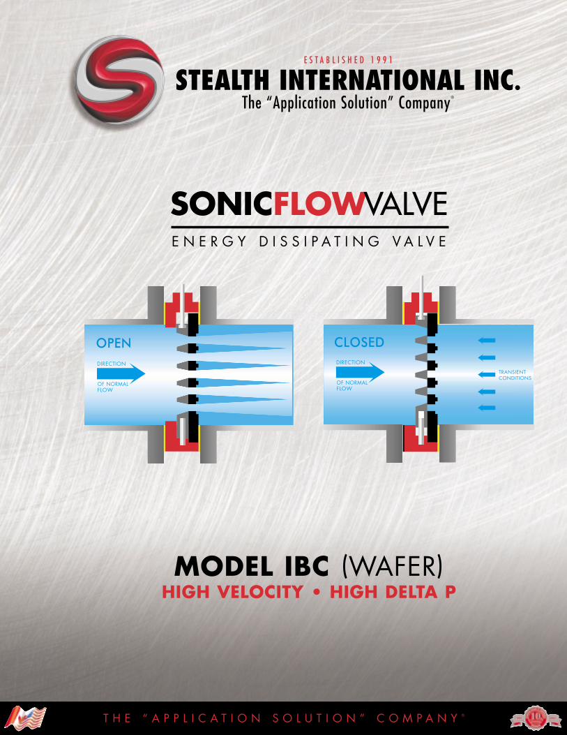
In the fully open position, the orifices in the plates are inline.The fully closed position is obtained by displacing theupstream plate. The upstream plate moves vertically the fulltravel equal to one full orifice diameter. Upward operation is to close the valve.Under specified flow control conditions,the position is intermediate, with the orifices in the fixed plate only partially blocked off by those of the mobile P1plate. The valve is automated by a control device per the customer’s specifications.
FUNCTIONThe high velocity dissipation design prevents typical disturbances in the flow. Typically, large fluctuations in flow and Delta P cause vibration of the pipe work, createdamaging cavitation (i.e. fluid vapour bubbles), and noise.Noise is caused by the sudden, explosive collapse of cavitation or bubbles.
In Stealth Sonic Flow Valves, energy dissipation is controlled by multiple, evenly distributed jets into which perforated plates divide the flow equally. Uncontrolled fluctuations of flow are reduced due to the jet induction port design.
The distance in which the energy is dissipated is linear in a short distance and controlled relative to positioning in the downstream pipe.
Stealth Sonic Flow Valves have cavitation inception figures which are more desirable than conventional control valves.
Cavitation does not create a hazard within the valve ordownstream. This condition exceeds the typical performanceof conventional control valves where cavitation is frequentlyobserved within the body or downstream. Vapour cavities are not created when Stealth Sonic Flow Valves are properly sized, eliminating pressure oscillation risks.
Stealth Sonic Flow Valves do not have a tendency to open or close under flowing conditions typically found inbutterfly valves, due to the unique Stealth Anti-Hydraulic liftdesign in the lower shaft.
Figure A
2 DownstreamPlate (Fixed)
1 Annular BodyUpstream Plate Linear 3
Lower ShaftPatent Pending
Transient FlowReversal Design
DESIGN ADVANTAGESThe Stealth Sonic Flow Valve Model IBC manual, hydraulically or electrically operated flow control valves are specially designed for extremely high velocity and highpressure drop applications. Their effectiveness is due to thelarge number of engineered orifices into which the flowingmedia is divided creating a specified throttling effect. These jets are evenly distributed over the entire face of theupstream valve plate. The uniform, venturi-jet configurationsuppresses unwanted operating hazards such as vibration,cavitation, pressure fluctuations and noise.
OPERATING PRINCIPLE (Bi-Directional)The simplicity of the Stealth Sonic Flow Valve Model IBC is described and illustrated in Figure A.Valve plates are fixed (2) and linear (3).
Both plates are perforated.1. An annular body is mounted between pipe flanges. 2. Down Stream Plate is fixed and locked into position. 3. Linear Upstream Plate slides and is guided top and bottom.

BENEFITS
1. No damage to the upstream plate oractuator
2. No possibility of misalignment (Bi-directional)3. No damage to pipe or valve internals4. Smaller actuation package5. Lower torque, reduced wear on mating
surfaces6. Reduced plate deflection and reduced
wear with lower frictional thrust required7. Shafts are locked in place and maintain
their full diameter8. Full control packages9. Ease of removal of the fixed plate
10. Noise reduction during bi-directional conditions11. Accommodates all piping configurations
12. Corrosion free surface for seals and packing13. Prevents disc shift, allows for horizontal
mounting and intermittent bi–directional flow14. Allows for ease of disassembly of the fixed plate.
Eliminates corrosion and fixed plate seizure15. Independent adjustable manual indication in
the event of actuator adjustment or removal16. ’O’-Ring seals are replaceable under pressure17. No corrosion in the upper body or the linear
plate lower shaft bore18. The taper ring incorporates a dielectric link with
a low coefficient of friction with the linear plate.The design allows for intermittent bi–directionalflow or transient conditions. This taper ring alsoeliminates corrosion or seizure during long periods of valve inactivity
19. ’O’-Ring seals are removable in the upperand lower shafts without valve removal orsystem depressurization
20. For ease of disassembly and assembly21. Ease of assembly to ensure proper
orientation of the upper and lower plates22. Allows for horizontal mounting and operation
Stainless SteelBearing Journal
Lower Shaft
Fixed PlateDielectric Link
Non-MetallicBearings
Taper Ring
FEATURES
1. Capable of transient conditions and reversal of flow (Patent Pending)
2. Guided P1 plate (lower shaft)3. Eliminates cavitation4. Short operation of travel and reduced thrust5. Low co-efficient of friction barrier on
both mating surfaces6. Thicker plate construction coated and
hardened7. Blow-out-proof stems (upper and lower)
8. Manual or automated control9. Anti-corrosion ring
10. Taper ring11. Valve shafts can be mounted vertically or
horizontally due to lower shaft guiding12. Stainless steel bearing Journals13. Lower shaft
14. Fixed plate dielectric link
15. Visual Indication
16. Retained chevron packaging17. Non–metallic bearings
18. Taper ring
19. Removable O–Ring seals
20. Disc lifting holes21. Asymmetric design
22. Double T–shaft design
T H E “ A P P L I C A T I O N S O L U T I O N ” C O M P A N Y ®
Anti-Corrosion Ring
DuralonBearing
‘O’-Ring Seals
Top Stem Packing and Seal Detail (Patented)The patented stem seal allows for bushing and ‘O’-Ring replacement, while under pressure.The self-adjusting chevron packing is live loaded and internally retained. Adjustment is not required and the chevron packing is maintenance free. No lubrication is required. The ‘O’-Ring seals are self contained, dynamic and static, housed in a non-corrosive, non-metallic bushing that also maintains the loading on the chevron packing.
Bottom Stem and Seal Detail (Patent Pending)The lower stem maintains the moving linear plate in any position during intermittent bi-directional conditions. The unique stem design incorporates relief ports, eliminatinghydraulic lift or position lock. The stem is guided in a Duralon bearing, eliminating shaft journal corrosion. Sealing is maintained with static ‘O’-Ring seals with the stem bolted in place. A secondary security cap is bolted and sealed to ensure a positive seal, requiring no adjustment. The body retaining step for the fixed plate incorporates an anti-corrosion ring that permits easy removal of the fixed plate should disassembly be required.
Stealth Sonic Flow Valve
YesYes
Yes (standard)
Yes NoneYes
**Yes *Yes *Yes Yes Yes
**Yes Standard
Yes
*Yes Yes
TYPICAL REQUIRED FEATURES
FeatureDouble Plate DesignUpward Operation to CloseHardened PlatesManufactured in CanadaObsolete DesignsStandard Design – All SizesBi-Directional Capabilities Flow ReversalLower Shaft and SealsReplaceable Seals Under PressureRTFE Taper Rings – Carbon Steel Delron BackedPatented Rotary Seal SystemAnti-Hydraulic LiftBody Coatings to NSF1st Plate Anti-Corrosion Ring forField Replacement or Inspection in BodyBackup ’O’Ring Shaft Seals – Replaceable Under PressureOptional Materials – (316SS, 42OSS, 17-4PH)
*Patented **Patent Pending
T H E “ A P P L I C A T I O N S O L U T I O N ” C O M P A N Y ®
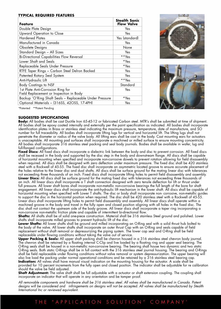
SUGGESTED SPECIFICATIONSBody: All bodies shall be cast Ductile Iron 65-45-12 or fabricated Carbon steel. MTR’s shall be submitted at time of shipment.All bodies shall be epoxy coated internally and externally per the paint specification as indicated. All bodies shall incorporateidentification plates in Brass or stainless steel indicating the maximum pressure, temperature, date of manufacture, and SOnumber for full traceability. All bodies shall incorporate lifting lugs for vertical and horizontal lift. The lifting lugs shall not penetrate the diameter or radius of the valve body. All lifting ears shall be cast in the body. Cast mounting ears for actuatorsis unacceptable. All mounting pad surfaces shall incorporate a machined or milled surface to ensure mounting concentricity.All bodies shall incorporate 316 stainless steel packing and seal body journals. Bodies shall be available in wafer, lug andfull-flanged configurations.Fixed Discs: All fixed discs shall incorporate a dielectric link between the body and disc to prevent corrosion. All fixed discsshall be recessed in the body and supported by the disc step in the body and downstream flange. All discs shall be capableof horizontal mounting when specified and incorporate non-corrosive dowels to prevent rotation allowing for field disassemblywhen required. All discs shall be designed with zero deflection under maximum pressure. The fixed disc shall be 420 stainlesssteel with a Rockwell of 45-55. The fixed disc shall incorporate an asymmetric located groove to ensure accurate placement ofthe holes relative to the linear disc and dual shafts. All discs shall be surface ground for the mating linear disc with tolerancesnot exceeding three thousands of an inch. Fixed discs shall incorporate lifting holes to permit field disassembly and assembly. Linear Discs: All discs shall be surface ground for the mating fixed disc with tolerances not exceeding three thousands of an inch. All linear discs shall incorporate a T shaft connection designed with zero tensile deflection for lift or thrust under full pressure. All lower shaft bores shall incorporate non-metallic non-corrosive bearings the full length of the bore for shaftengagement. All linear discs shall incorporate the anti-hydraulic lift mechanism in the lower shaft. All discs shall be capable ofhorizontal mounting when specified with Lower T shafts. The disc or body shall incorporate non- corrosive, non-metallic guidesto support the disc in the horizontal position when required. The disc shall be 420 stainless steel with a Rockwell of 45-55.Linear discs shall incorporate lifting holes to permit field disassembly and assembly. All linear discs shall operate within amachined groove in the body and travel in the fully open and closed position aligning with all holes in the fixed disc. The disc shall not contact the upstream side of the body groove. All linear discs shall incorporate a taper ring incorporating a non-corrosive non-metallic friction plate and capable of intermittent bi-directional flow.Shafts: All shafts shall be of solid one-piece construction. Material shall be 316 stainless Steel ground and polished. Lowershafts shall incorporate milled grooves to prevent hydraulic lift of the disc.Lower Shafts: All lower shafts shall be ground and milled incorporating an O-Ring seal with a solid thrust hub bolted to the body of the valve. All lower shafts shall incorporate an outer thrust Cap with an O-Ring and seals capable of fieldreplacement without shaft removal or depressurizing the piping system. The lower cap seal and O-Ring shall be field replaceable under flowing conditions without taking the valve out of service.Upper Packing & Seals: All upper shaft packing shall be chevron housed in a 316 stainless steel chevron body journal.The chevron shall be retained by a floating internal C-Clip and live loaded by a floating ring and upper seal bearing. The O-Ring seals shall be housed in a non-metallic non-corrosive bearing. The bearing shall house two dynamic and two static O-Ring seals. Both static O-Rings shall be in full contact with the 316 stainless steel journal housing. The bearing and O-Ringsshall be field replaceable under flowing conditions without valve removal or system depressurization. The upper bearing willalso live load the packing under normal operational conditions and be retained by a 316 stainless steel bearing cap.Indication: All valves shall have manual visual indication on the mounting housing for the actuator. A scale shall be provided for 10 percent increments from the fully open and closed position. The indicator shall be adjustable for re calibrationshould the valve be field adjusted.Shaft Adjustment: The valve shaft shall be full adjustable with a actuator or shaft extension coupling. The coupling shall incorporate an indicator that will operate in any orientation and be tamper proof.
All removable components and hardware shall be 316 stainless steel. All valves shall be manufactured in Canada. Patentdesigns will be considered and infringements on designs will not be accepted. All valves shall be manufactured by StealthInternational Inc or reviewed equivalent.

E N E R G Y D I S S I P A T I N G V A L V E
REQUIRED INFORMATIONFor Application calculations of IBC Valve and Actuator Sizing,allowable cavitation factor, the following information is required:• Upstream pressure and downstream pressure at minimum flow
• Maximum and minimum upstream pressure• Sketch of pipe system at the valve• Type of actuator and power available• Control signals and feedback requirements
WEIGHT
IBC Cv VALUES
Percent of Valve Opening
Size468
10121416182024303642485460
100%170390680
10701540218026703270426061409650
1386018320247503069037920
90%160370660
10201470208025603110406058609200
1321017475235302919036160
80%130280495790
10901480198025303170456072309900
13360178202277027720
70%90
210380610840
11501520191024253460520081809700
127301616019700
60%60
105250400565770990
1270159022303565505068309110
1139014160
50%50
140190400430590760970
1200169025253740505066708490
10400
40%3070
125190280380495630770
1090176025253370445557406930
30%205080
130190250320410500730
115016202220283037404650
20%10305070
100140180230275420650910
1240168021802580
10%5
10153040607080
130175250380490670810
1070
5%15
101215203035506590
150180250300400
T H E “ A P P L I C A T I O N S O L U T I O N ” C O M P A N Y ®

E N E R G Y D I S S I P A T I N G V A L V E
HYDRAULIC CHARACTERISTICS
CAVITATIONThe tendency of a valve to cavitate is usually characterized by a cavitation number defined as:
Where,P1 = absolute upstream pressure measured in practice one
pipe diameter above the valve, valve inlet pressure in PSIAP2 = absolute pressure measured 10 pipe diameters below the
valve and corrected for friction losses between points 1 and 2, valve outlet pressure in PSIA
Pv = vapour pressure of the liquid at the operating temperature at the valve inlet in PSIA
Kc = cavitation index or dimensionless
These pressure values are generally expressed as liquidmetres of head. Some valve manufacturers utilize a cavitationnumber defined as:
OR
CAVITATIONAL INDEX
Typical Test Curve showing Kc and Km points.
Cavitation is the implosion of vapour bubbles which form in a flowing liquid when the pipeline pressure at some pointdecreases to below the vapour pressure of the liquid. Theimplosion is caused by a subsequent increase in pipelinepressure point to a value exceeding the vapour pressure ofthe liquid. Valves located in pipelines are a common cause of cavitation due to the increased velocities and lowered pressures caused by their effect on the flowing fluid.
CAVITATION (continued)Cavitation caused by valves is mathematically predictable viathe equation:
Reference Material: ISA (Instrument Society of America) Handbook Second Edition
∆PMAX = pressure drop at which damaging cavitationoccurs
F1 = liquid pressure recovery factor based upon valvetype and travel
P1 = inlet pressure - (PSIA)Ff = liquid critical pressure ratio – dimensionlessPv = liquid vapor pressure – PSIA
WATER HAMMER
Tm= minimum closing time in secondsL = pipe length in feet from the tank or closure upstream
to the automated valve in questionV= velocity at inlet in ft/sec under normal conditionsP= maximum pressure rating of valve in PSI in the
closed positions
HEAD LOSSThe pressure drop caused by flow through StealthSonic Flow Valves is written as:
Where,∆H = the pressure drop in water column metres at a
given valve opening,kc= the (dimensionless) head loss co-efficient at the
same valve opening,V= the velocity of the liquid in metres per second
computed on the basis of the nominal flow section of the valve,
g = gravitational acceleration in metres per secondsquared.
SPECIFIC FLOWSpecific flow is defined as the flow passing through aone-metre diameter Stealth Sonic Flow Valve whichcauses a head loss equal to one metre head of flowingliquid. Specific flow q11 may be written in terms of headloss as:
Where,q = specific flow in m3/s at a given valve opening, the
total flow passing through the valve in m3/s,Q = the total flow passing through the valve in m3/s,
∆H = the head loss in water column metres liquid at thesame valve opening,
D = is the nominal IBC diameter in metres.
In the fully open position, the specific q of a StealthSonic Flow Valve with maximum perforated areainstalled in a pipe whose diameter is equal to the nominaldiameter of the valve is 1.3 m3/s. The specific flow valuedrops to 0.95 m3/s for an end-mounted valve.
T H E “ A P P L I C A T I O N S O L U T I O N ” C O M P A N Y ®

E N E R G Y D I S S I P A T I N G V A L V E
NOTE: All Dimensions are approximateand subject to design modifications
D
AE
STEALTHINTERNATIONAL
INC.d
(E) Electric
A
(M) Manual
DSTEALTH
INTERNATIONALINC.
STEALTHINTERNATIONAL
INC.
Downstream View
Hydraulic/Pneumatic
B
Dimensions and weights are approximate and for reference only, subject to change.Please request certified drawings once actuation has been determined.Dimensions based on 150 lb flanges in sizes 4” (100mm) through 28” (700mm) and 32” (800mm) through 60 (1500mm) AWWA Table 3 Class E steel hub flanges
Size4”4”6”6”8”8”
10”10”12”12”14”14”16”16”18”20”24”28”30”32”36”40”42”48”54”60”
DN100100150150200200250250300300350350400400450500600700750800900
10001050120013501500
Act.MEMEMEMEMEEMME
E/ME/ME/ME/ME/ME/ME/ME/ME/ME/ME/ME/M
A (mm)
228228279279342342406406482482533533596596635698812927984
1060116812891346151116822032
B (mm)
100100100100100100100100150150150150150150150150200200200200200200200200250250
C (mm)
250383250383250383315475400475500500500400500580580580580580580580580580580580
D (mm)
390480516580587645727795757850920920943
1160144017201840192019902040215022802350246026702770
E (mm)
–290
–320
–350
–377
–400400400
–602845900960
101011701060112011701280128013801440
d77
11111515181822222525292933364350545865727987
102109
KG133123444053649291
228137181170247394552644690729805920
10351105126516101955
LBS2868519788
117142203200503300398375545865
12171420152116031775202922822431278935504311
WEIGHT
MODEL IBCDimension & Weights
I s o l a t i o n • B i - d i r e c t i o n a l • C a p a b i l i t i e s
INSTALLATIONThe valves may be installed in both vertical and horizontalpipes. In vertical pipes the flow should preferably be downward. Valves mounted horizontally should be placedwith the actuator at the 12 o’clock position. Valves will operate with the shafts mounted vertically or in the horizontalposition. Horizontal mounting must be specified prior to manufacturing. Plate shoes must be incorporated.
RATING150 PSIG/300 PSIG
APPLICATIONSPrimary control variables include flow rate, inlet pressure, temperature, elevation and specific gravity.
• Water supply systems• Industrial flow, cooling and mixing systems• Head works of water treatment plant• Flow relief for pump and turbine units• Water intake at the foot of a dam• Laboratory test-rigs• Tank discharge free flow conditions
Distributed by:
Manufactured in Canada Printed in Canada
STEALTH INTERNATIONAL INC.The “Application Solution” Company®
E S T A B L I S H E D 1 9 9 1
STANDARD MATERIALS OF CONSTRUCTIONBody: A-36 Carbon Steel/Ductile IronFixed Plate: AISI 420Moving Plate: AISI 420Support: A-36Stem: 316 Stainless SteelFlange and Stem Seals: 70 Shore-hardness, BUNA-N or Viton®
OPTIONALDuctile Iron, 316SS17- 4PH, 316SS
All 420 material is hardened to a Rockwell hardness ofbetween R40 to R50. Other materials can be hardened.
MOUNTINGStealth Sonic Flow Valves are designed to be mountedbetween all pipe flanges. Stealth ensures alignment with locating lugs on the valve body. Dead end mounting isachieved with the use of a mandatory downstream flange.
TEMPERATURE °C °FMINIMUM: -20 -4MAXIMUM: 500 932OPERATING: 0–250 32–482
OTHER RELATED PRODUCTS AND SERVICES• Ross® Valve WaterTamer• Crispin® Air and Vacuum Release Valves• Stealth Damper Valves• Stealth Deflector Valves• Crispin® Check Valves• Stealth Pedestals and Shaft Extensions• Stealth Torque Tubes• Stealth Priming Systems• Stealth Rod Extensions• Automation and Mounting• Self-cleaning Automatic Strainers• Stealth Knife Gate Valves• Pratt® AWWA Valves
– Model IBC
ONTARIO – 1273 North Service Road East, Unit F6, Oakville ON L6H 1A7 – TEL 905 845 4500 • FAX 905 845 45052520c St. Laurent Boulevard, Suite 102, Ottawa ON K1H 1B1 – TEL 613 739 4626 • FAX 613 739 1679
BRITISH COLUMBIA – TEL 604 632 4657 • FAX 604 632 4658QUEBEC – 3460 Poirier, St. Laurent QC H4R 2J5 – TEL 514 332 4260 • FAX 514 331 3924 • TOLL FREE 1 800 361 5571
[email protected] www.stealthvalve.com®
VISIT OUR APPLICATION DATA SHEETS ON THE WEB
M MUNICIPAL I INDUSTRIAL P POWERC COMMERCIAL
• 2 4 H O U R E M E R G E N C Y VA LV E R E S P O N S E • 4 1 6 9 4 5 1 2 5 8 •