energizer zinc air prismatic handbookpower to miniature hearing aids. zinc air chemistry provides...
TRANSCRIPT

Energizer Zinc Air Prismatic Handbook Including performance and design data for the PP355

P a g e | 2
ENERGIZER BATTERY MANUFACTURING
VERSION 1.2
Energizer Zinc Air Prismatic Handbook
1. Battery Overview ............................................................................................................................. 3
1.1 Zinc Air Chemistry ............................................................................................................................... 3
1.2 Construction ........................................................................................................................................ 3
1.3 Features of Zinc Air Prismatic ............................................................................................................. 4
1.4 Zinc Air Prismatic Battery Sizes ........................................................................................................... 6
2. PP355 Performance Characteristics .................................................................................................. 7
2.1 Performance at Standard Conditions .................................................................................................. 7
2.2 Performance at Other Environmental Conditions .............................................................................. 8
2.3 Pulse Capability ................................................................................................................................... 9
2.4 Service Maintenance ......................................................................................................................... 10
2.5 Activation Time and Air Requirements ............................................................................................. 11
3. Application and Design Considerations .......................................................................................... 12
3.1 Air Management ............................................................................................................................... 12
3.2 Elements of Air Management ........................................................................................................... 13
3.3 Battery Compartment ....................................................................................................................... 14
3.4 Multi‐Battery Applications ................................................................................................................ 16
3.5 Recommended Cutoff Voltage .......................................................................................................... 16
3.6 Fuel Gauging ...................................................................................................................................... 16
4. Handling Procedures ...................................................................................................................... 17
4.1 Recommended Operating and Storage Conditions .......................................................................... 17
4.2 Polarity Markings .............................................................................................................................. 17
4.3 Safety ................................................................................................................................................ 17
4.4 Battery Disposal ................................................................................................................................ 17

P a g e | 3
ENERGIZER BATTERY MANUFACTURING
VERSION 1.2
Section 1: Battery Overview For over 35 years, Energizer has manufactured miniature Zinc Air batteries primarily designed to provide power to miniature hearing aids. Zinc Air chemistry provides the highest available energy density compared to other commercially available batteries. Energizer Zinc Air Prismatic batteries employ technology similar to what is used in hearing aid batteries, but with a thin prismatic form factor providing power for a broad range of applications.
1.1 ‐‐ Zinc Air Chemistry Zinc Air batteries are based on the alkaline chemistry (Zn/MnO2) used in standard AA and AAA primary batteries. The high energy density of Zinc Air results from replacing the manganese dioxide (MnO2) cathode with a thin air electrode. This air electrode contains carbon which catalyzes oxygen to allow it to react with zinc. The thin air electrode eliminates the need to contain both reactants in the battery, so the majority of the battery can be filled by the zinc anode. As a result Zinc Air provides the highest available energy density compared to commercially available batteries. The typical open circuit voltage (OCV) of Zinc Air is 1.4 V. Under load, the operating voltage is generally between 1.10 and 1.30 volts. The half cell and overall reactions for a Zinc Air battery are as follows:
Anode: 2Zn + 4OH‐ → 2ZnO + 2H2O + 4e‐
Cathode: O2 + 2H2O + 4e‐ → 4OH‐
Overall: 2Zn + O2 → 2ZnO
1.2 ‐‐ Construction Air holes are designed into the battery container to allow oxygen to flow into the battery. Because exposure to the environment can degrade battery performance over time, the air holes are sealed by a tab prior to consumer use. The tab must be removed before the battery is placed into a device. Once air enters the holes, it flows through an air distribution layer. This layer helps to distribute air across the entire air electrode. Figure 1 shows a cross section of an Energizer Zinc Air prismatic battery.

P a g e | 4
ENERGIZER BATTERY MANUFACTURING
VERSION 1.2
Figure 1: Cross Section View of Zinc Air Prismatic Battery
Energizer Zinc Air Prismatic batteries are designed to allow air to enter the air holes and to prevent the transport of liquid electrolyte out of the battery. A gasket is used to seal between the anode cup and the cathode can. The gasket also electrically insulates the negative cup from the positive can. An air electrode and a loose layer of Teflon are compressed onto a band of sealant on the bottom of the can. This Teflon layer allows gasses to enter the battery while preventing liquid from passing through.
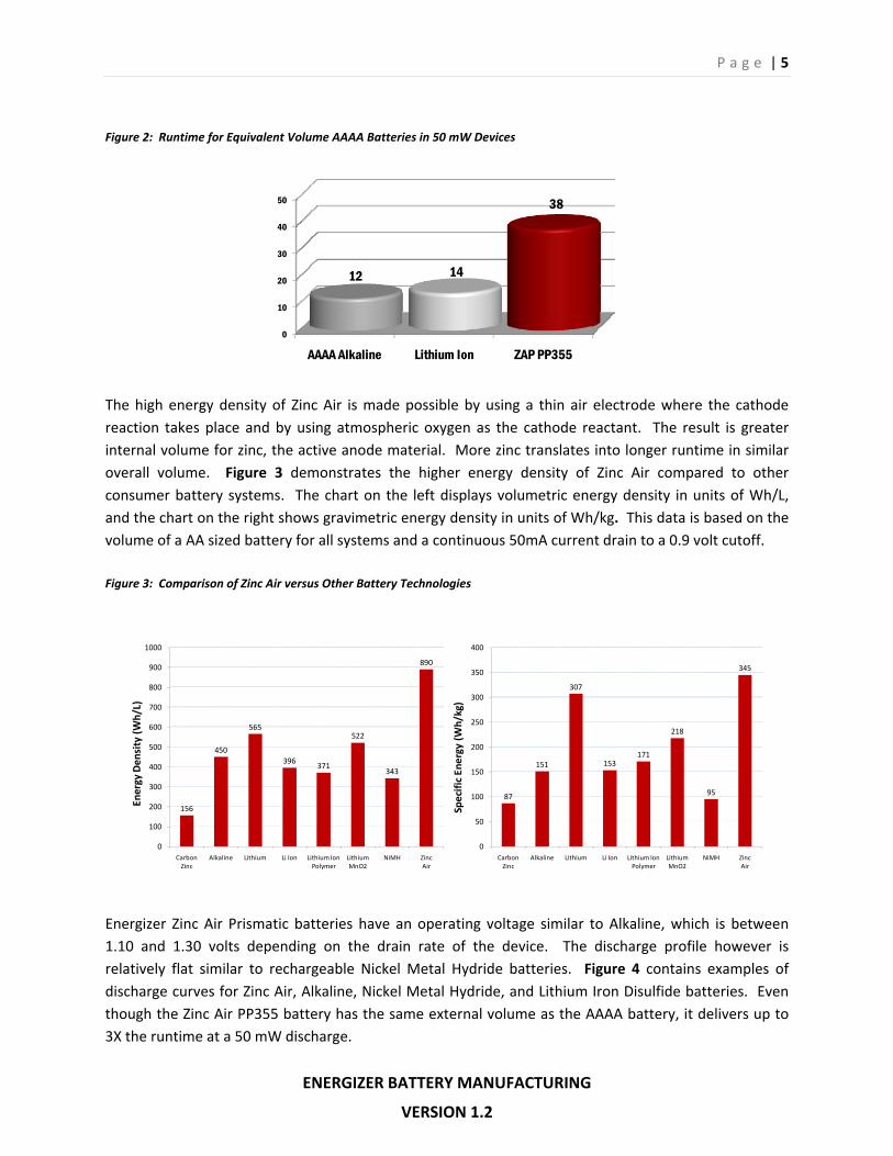
1.3 ‐‐ Features of Zinc Air Prismatic Energizer’s Zinc Air Prismatic batteries offer a 5 mm thin, prismatic construction designed to work with a variety of applications. This shape is consistent with the low profile design of today’s devices, often requiring a thinner battery solution. The thinnest round cell available is the AAAA battery at approximately 8 mm, and many Lithium Ion rechargeable solutions have a thickness of 5 mm. Energizer Zinc Air Prismatic batteries also offer the opportunity to significantly lower manufacturer costs. It is likely that the cost of a Zinc Air Prismatic battery solution will be less than the cost of a Lithium Ion battery. Adding to the cost of a Lithium Ion solution is the cost of circuitry for charge and discharge control, which is not needed with Zinc Air Prismatic batteries. Furthermore Zinc Air Prismatic batteries are ready to be used out of the package. There is no need for charge adaptors. Energizer Zinc Air Prismatic batteries can last up to 3X longer than comparable volume battery systems. This service advantage is due to Zinc Air technology offering the highest energy density for non‐rechargeable and rechargeable consumer batteries. Figure 2 demonstrates this advantage over Alkaline and Lithium Ion batteries of similar volume.
P a g e | 5
ENERGIZER BATTERY MANUFACTURING
VERSION 1.2
Figure 2: Runtime for Equivalent Volume AAAA Batteries in 50 mW Devices
0
10
20
30
40
50
AAAA Alkaline Lithium Ion ZAP PP355
12 14
38
The high energy density of Zinc Air is made possible by using a thin air electrode where the cathode reaction takes place and by using atmospheric oxygen as the cathode reactant. The result is greater internal volume for zinc, the active anode material. More zinc translates into longer runtime in similar overall volume. Figure 3 demonstrates the higher energy density of Zinc Air compared to other consumer battery systems. The chart on the left displays volumetric energy density in units of Wh/L, and the chart on the right shows gravimetric energy density in units of Wh/kg. This data is based on the volume of a AA sized battery for all systems and a continuous 50mA current drain to a 0.9 volt cutoff. Figure 3: Comparison of Zinc Air versus Other Battery Technologies
156
450
565
396371
522
343
890
0
100
200
300
400
500
600
700
800
900
1000
Carbon Zinc
Alkaline Lithium Li Ion Lithium Ion Polymer
LithiumMnO2
NiMH Zinc Air
Energy Den
sity (W
h/L)
87
151
307
153171
218
95
345
0
50
100
150
200
250
300
350
400
Carbon Zinc
Alkaline Lithium Li Ion Lithium Ion Polymer
LithiumMnO2
NiMH Zinc Air
Specific En
ergy (W
h/kg)
Energizer Zinc Air Prismatic batteries have an operating voltage similar to Alkaline, which is between 1.10 and 1.30 volts depending on the drain rate of the device. The discharge profile however is relatively flat similar to rechargeable Nickel Metal Hydride batteries. Figure 4 contains examples of discharge curves for Zinc Air, Alkaline, Nickel Metal Hydride, and Lithium Iron Disulfide batteries. Even though the Zinc Air PP355 battery has the same external volume as the AAAA battery, it delivers up to 3X the runtime at a 50 mW discharge.

P a g e | 6
ENERGIZER BATTERY MANUFACTURING
VERSION 1.2
Figure 4: Comparison of Discharge Curves at 50 mW Continuous
0.4
0.6
0.8
1.0
1.2
1.4
1.6
0 5 10 15 20 25 30 35 40 45
Volta
ge (V)
Discharge Time (hrs)
LithiumAAA
Alkaline AAAAlkaline
AAAA
Zinc Air PP355
NiMHAAA
The impedance of Energizer Zinc Air Prismatic batteries is higher than similar volume Alkaline batteries, and it decreases slightly through the life of the battery. The impedance should not impact battery performance at low to moderate discharge rates. At higher rate discharges, this higher impedance will reduce operating voltage and delivered energy. 1.4 ‐‐ Zinc Air Prismatic Battery Sizes Energizer Zinc Air Prismatic batteries provide an ideal form factor for devices with a thin profile. The family of battery sizes is shown in Figure 5, ranging from AAA Alkaline volume equivalent to ½ the AAAA Alkaline volume equivalent. Energizer Zinc Air Prismatic battery nomenclature is determined by the IEC standard. The first ‘P’ indicates Zinc Air chemistry, the second ‘P’ indicates the prismatic form factor, the first two digits represent the diagonal in mm, and the last digit is the battery height in mm. For example the PP355 has a 35 mm diagonal distance and a height of 5 mm. Figure 5: Zinc Air Prismatic Battery Sizes
PP425 PP355 PP255Length (mm) 36.0 32.2 22.6Width (mm) 22.0 14.7 10.3Thickness (mm) 5.0 5.0 5.0
Volume (cm3) 3.96 2.37 1.16Cell Weight (g) 11.7 6.8 3.4Continuous Rate Capability < 200 mW < 100 mW < 50 mWCapacity Rated (mAh) 3600 1800 720

P a g e | 7
ENERGIZER BATTERY MANUFACTURING
VERSION 1.2
Section 2: PP355 Performance Characteristics This section describes the performance of the PP355 battery. Standard discharge curves, performance at a variety of environmental conditions, pulse capability, and service maintenance data are presented.
2.1 ‐‐ Performance at Standard Conditions Standard conditions for Energizer Zinc Air Prismatic batteries are defined as 21°C and 50% relative humidity (RH). Under these conditions, the PP355 battery is designed to provide continuous discharge capability up to 100 mW. While best performance is obtained in standard conditions and continuous duty cycles, Energizer Zinc Air Prismatic Batteries perform well over a wide range of environmental conditions and in intermittent applications as well. Figure 6 contains typical discharge curves for the PP355 under standard conditions and constant power loads of 25, 50, 75, and 100 mW. Figure 6: PP355 Discharge Curves at Continuous Constant Power
0.8
0.9
1.0
1.1
1.2
1.3
1.4
0 500 1000 1500 2000 2500
Voltage (V)
Discharge Energy (mWh)
100 mW
75mW
50mW
25 mW
Energizer Zinc Air Prismatic batteries significantly outperform existing Alkaline cylindrical solutions of equivalent volume. To demonstrate this advantage, Figure 7 shows how PP355 and AAAA Alkaline batteries perform on the same continuous power tests. The PP355 lasts longer than the alkaline AAAA even though the volumes of both battery types are approximately the same at 2.37 cc and 2.2 cc, respectively.

P a g e | 8
ENERGIZER BATTERY MANUFACTURING
VERSION 1.2
Figure 7: Comparison of Performance under Continuous Constant Power
AAAA PP355
25 mW 24 88
50 mW 11 38
75 mW 6 24
100 mW 4 15
Continuous Discharge Time (hrs)
2.2 ‐‐ Performance at Other Environmental Conditions When a Zinc Air battery is exposed to a non‐standard environment, a driving force for water transport in or out of the battery exists. Movement of water vapor into the battery can fill void space in the anode cavity under high humidity environments, and movement of water vapor out of the battery can dry out the electrolyte in low humidity environments. Either situation can decrease battery performance over time. Understanding the environmental conditions that a battery might encounter is critical to estimating battery performance. A study was done at Energizer to determine realistic extreme conditions for battery testing, using climate data from 61 cities across the globe. These cities represent the major markets for both devices and batteries. Combinations of daily morning and afternoon temperature and humidity were compiled and analyzed to determine reasonable temperature and humidity extremes. Hot and Humid Conditions: Zinc Air Prismatic batteries can take on water when exposed to hot and humid conditions. This can limit battery performance by taking up void volume in the air electrode and anode compartment. At 35°C and 75% RH conditions, there is a driving force for water gain larger than 99% of conditions seen in combined indoor and outdoor data from the top 61 cities globally. Service tests with the PP355 under these conditions show very good service even at 1 hr per day intermittency. Hot and Arid Conditions: Zinc Air Prismatic batteries can lose water when exposed to hot and arid conditions which can limit battery performance by drying out the battery. Under 35°C and 25% RH conditions, there is a driving force for water loss larger than 99% of conditions seen in combined indoor and outdoor data from the top 61 cities globally. Service testing with the PP355 at these conditions shows very good service even at 1 hr per day intermittency.

P a g e | 9
ENERGIZER BATTERY MANUFACTURING
VERSION 1.2
Lower Temperature Conditions: Air holds less moisture as temperature decreases, and the difference between low and high relative humidity becomes less significant. At 0°C, the difference between the humidity of the PP355 and the environment is negligible. While the service obtained from a PP355 at temperatures lower than standard conditions is less, the loss is similar to Alkaline batteries. In general the “up to 3X” service advantage for Zinc Air batteries over Alkaline batteries is maintained. Figure 9: Service Summary for Zinc Air Prismatic Batteries at Various Environmental Conditions
Humid (35°C / 75% RH)
Typical (21°C / 50% RH)
Arid(35°C / 25% RH)
Cold (0°C)
50 mWContinuous
45 hrs(2 days)
38 hrs(2 days)
40 hrs(2 days)
12 hrs(0.5 days)
50 mW1h per 12hr
38 hrs(19 days)
36 hrs(18 days)
30 hrs(15 days)
16 hrs(8 days)
50 mW1h per 24hr
25 hrs(25 days)
30 hrs(30 days)
17 hrs(17 days)
-
AA
AA
Alk
alin
e
50 mW5 hrs
(0.25 days)
PP
35
5
generally about 12 hrs (0.5 days) for these temperatures and all intermittencies
Each battery was exposed to the specified conditions for the entire test duration.
Figure 9 demonstrates the service obtained from a PP355 battery at 35°C/75% RH, 35°C/25% RH, and 0°C conditions. The data presented with units of hours represent the runtime that the battery delivered, while the values in parentheses indicate the duration of the test in days. In summary, the PP355 battery sustains a significant performance advantage over similar volume Alkaline batteries with varying intermittency in extreme temperature and humidity conditions.
2.3 ‐‐ Pulse Capability The pulse capability of Zinc Air batteries is dependent on the instantaneous amount of oxygen available at the air electrode at a given time. While the PP355 battery can continuously discharge at rates up to 100 mA, the battery can provide significantly more current in short bursts. Figure 8 demonstrates that a fresh PP355 battery can provide pulses of up to 1500 mA, depending on the duration of the pulse. The pulse capability of a Zinc Air battery can also be affected by the frequency of the pulses. Pulse capability will drop over time without sufficient time for more oxygen to enter the air electrode.

P a g e | 10
ENERGIZER BATTERY MANUFACTURING
VERSION 1.2
Figure 8: Pulse Capability of PP355 Batteries
0.0001
0.001
0.01
0.1
1
0 200 400 600 800 1000 1200 1400 1600
Maxim
um Pulse Duration (s)
Current (mA)
1.1V Cutoff
1.0V Cutoff
0.9V Cutoff
0.8V Cutoff
2.4 ‐‐ Service Maintenance Zinc Air batteries are stored with adhesive backed tabs prior to use. These tabs seal the air holes against oxygen and water ingress. To obtain the full battery performance, the tab should be removed only immediately prior to use. When the battery is sealed by the tab, service loss due to self discharge is approximately 5% per year. Figure 10 illustrates the rates at which capacity is lost with the tab on and the tab removed. Figure 10: Service Maintenance of Energizer Zinc Air Prismatic Batteries
80%
85%
90%
95%
100%
0 1 2 3 4
Rat
ed C
apac
ity
(%)
Shelf Life (yr)
unsealed(tab removed)
sealed (on tab)

P a g e | 11
ENERGIZER BATTERY MANUFACTURING
VERSION 1.2
2.5 ‐‐ Activation Time and Air Requirements
When batteries are stored with the adhesive tab intact, they have a lower open circuit voltage (OCV) since the oxygen contained in the battery is consumed during storage. When the tab is removed the OCV will rise as oxygen activates the air electrode. With multiple air holes for added rate capability, the PP355 may take a couple of seconds to air up enough to sustain a 50 mW load above 1 volt. Based on the time it will take a consumer to remove the tab, insert the battery into the device, close the battery compartment, the battery should be ready to support the device load when the user turns on the power. For maximum performance of a PP355 under a 50 mW continuous load, a minimum air flow rate of 2‐3 cc of air per minute is needed. For higher power demand devices (100 mW), a minimum of 4‐6 cc of air per minute is needed. In most devices this amount of air easily leaks into the battery compartment.

P a g e | 12
ENERGIZER BATTERY MANUFACTURING
VERSION 1.2
Section 3: Application and Design Considerations Excessive exposure to air can have an adverse affect on Zinc Air battery operation, primarily due to carbon dioxide reacting with the electrolyte in the air electrode. The battery can also absorb water or dry out depending on ambient conditions. Balancing the air requirement of the battery during discharge versus the need to minimize exposure during rest is called air management. Air management might be as simple as removing the tab from the battery and inserting it into a device, or it might include a system to open and control air access to the battery as needed. Air management is application specific, and most devices will require some degree of air management to optimize battery performance.
3.1 ‐‐ Air Management There are several types of air management. The simplest method of air management is removing the tab and putting the battery in the device. This is how miniature zinc air cells are used in hearing aids since the total battery life is typically expected to be 6‐8 weeks. As the device usage becomes more intermittent, other methods of air management are needed to deliver optimal battery performance. Throttling is a technique to permanently restrict air access to only what is needed by the battery in a specific application. Throttling is most appropriate in devices that require a small portion of the maximum current that a battery can sustain. For example, a device might require 10 mA of current compared to the maximum of 100 mA that a PP355 can sustain. This technique works best for devices that have a low average drain rate with little increased power needs. By restricting the air access to the battery, the performance life can be extended. As device use becomes more intermittent and as device power demands increase, valved (open and shut) air management becomes more appropriate. Valved systems are either mechanical or electronic. Each system requires a sealed battery or battery compartment, into which air is introduced by the valve when the device needs power. A seal can be accomplished with common materials such as o‐rings, gaskets, over‐molded or two‐part injection molded materials, or other methods. A mechanical solution might be an ON / OFF slide switch which acts as a simple air valve. Other device specific mechanical actions could also be used to open and close the air access. Examples include changing device settings, moving a piece or a part of the device during use, pressing a button, turning a dial, or manipulating a threaded component. An electronic valve would act in a similar fashion, except that the device electronics would open the air access automatically. A valve could be opened as a function of device state (on = open, off = closed), or it might be a function of the instantaneous power needs of the device. In a valved air management solution, a low level of air access might still be needed to be able to provide the quiescent, or background, power required to activate the ON/OFF valve. Figure 11 shows generally where each of these air management techniques is appropriate.

P a g e | 13
ENERGIZER BATTERY MANUFACTURING
VERSION 1.2
Figure 11: Overview of Different Air Management Techniques
high
low
continuous intermittent
none or small degree of air management
needed, since cell capacity is quickly
used(1‐3 months)
high degree of air management needed, cell has high air access but is expected to be in service with long periods of “off”
time (>3 months)
Duty Cycle
Discharge
Rate
throttling needed to maximize service time (>3 months)
3.2 ‐‐ Elements of Air Management Two elements of a successful in‐device air management system are a means for allowing controlled air access to the battery and an air plenum for even air distribution. An air plenum is an air gap, or volume, which has access to all of the air holes on the battery. The air plenum allows for more even air distribution over the battery air holes, and it provides a reserve of air immediately available to the battery to handle peak power needs. Controlling air access to the battery is accomplished by creating an access path to the sealed volume of air within a device. The air access path is designed to allow a desired amount of air to flow to the sealed volume of air, which includes the plenum, either continuously or intermittently. A sealed volume of air can be created by sealing an entire device, a portion of the device including the battery compartment, or just a plenum above the air hole side of the battery. The power requirements of the device determine the rate at which air is required to flow to the battery.
Figure 12 illustrates a simple, cost effective air management solution designed into a device. The compartment door contains an o‐ring which seals against the air hole side of the battery when the door is closed. The air plenum volume is defined by the compartment door and the sides of the o‐ring. A slide switch is located in the compartment door to create an air access point. The slide switch acts as a valve which seals the compartment when in the closed position and allows air to flow to the battery when in the open position. The slide switch could be mechanically manipulated by the user or electronically controlled by the device.

P a g e | 14
ENERGIZER BATTERY MANUFACTURING
VERSION 1.2
Figure 12: Air Management Design Concept
3.3 ‐‐ Battery Compartment The design of a Zinc Air Prismatic battery compartment depends on several factors including battery dimensions, battery orientation, and air flow needed to maintain power to the device. Other considerations are the ease of battery insertion and removal, contact materials, reversal protection, and the shape and location of device contacts. In general, consumers should be able to use and replace Zinc Air Prismatic batteries in a similar fashion to AA and AAA replaceable batteries with no additional actions required other than removing the tab from the Zinc Air Prismatic battery prior to use. Energizer Zinc Air Prismatic batteries are electrically conductive on all surfaces, and flat battery contacts are recommended. Leaf spring contacts are preferred over coil springs as coil springs are more prone to shorting. Positive contact should be made at the positive (+) can sidewall rather than on the air hole side of the battery to prevent unwanted air flow restrictions to the air holes. Negative contact should be centered on the negative (‐) cup bottom (non air hole side of battery) in such a way as to minimize potential shorting between the negative cup and the positive can sidewall. Figure 13 illustrates the recommended contact surfaces for Zinc Air Prismatic batteries. Figure 13: Zinc Air Prismatic Polarity
Contact surfaces area should be maximized to reduce contact resistance. Sufficient contact pressure should also be maintained to ensure consistent electrical connection but not so great as to deform the battery contacts. A contact force in the range of one half to two pounds is recommended.

P a g e | 15
ENERGIZER BATTERY MANUFACTURING
VERSION 1.2
Contact Materials: Nickel plated stainless steel is recommended because it provides good conductivity and environmental stability at a reasonable cost. Nickel plating must be adherent, continuous, and non‐porous. The nickel plating must also resist the wear that occurs during the insertion and extraction of batteries. The suggested plating thickness is 5‐6 micrometers. Battery Orientation: How the battery is situated in the compartment is an important design consideration. The location of the air access path, plenum, and seal are determined by the facing of the battery air holes. The orientation of the air hole side of the battery also influences the location of the electrical contacts. Determining the facing of the battery air holes is generally a function of device use and the position of the battery compartment within a device. Figure 14 presents an example of a device which orients a Zinc Air Prismatic battery with the air holes facing the compartment door. The cover holds the battery in place and does not restrict air flow to below what is required for device operation. Figure 14: Battery Orientation and Device Contacts
Reversal Protection: Battery reversal protection is recommended for battery operated devices to prevent against possible damage to a device or battery if a battery is inserted incorrectly. Reversal protection can be mechanical or electronic, depending on the device. An example of mechanical reversal protection is a design feature in the battery compartment that only allows the battery to be inserted with the correct polarity. This can be accomplished by including a raised lip or ridge that conforms to the battery contour when inserted in the correct polarity. The recommended location of the rib for Energizer Zinc Air Prismatic batteries is where the recessed edge around the non air hole side of the battery fits into the compartment. Battery Dimensions: Similar to other battery systems, Zinc Air batteries can bulge slightly under normal discharge conditions as zinc is converted to zinc oxide in the intended reactions. Energizer recommends designing devices around standard industry dimensions where available. Typical dimensional specifications for Energizer Zinc Air Prismatic batteries, including consideration for possible bulge, can be found on the respective datasheets.

P a g e | 16
ENERGIZER BATTERY MANUFACTURING
VERSION 1.2
3.4 ‐‐ Multi‐Battery Applications In some situations, a higher voltage or an increased performance level is desired for a certain application. Zinc Air batteries can be arranged in series or in parallel as needed. Devices that use more than one Zinc Air Prismatic battery introduce additional design considerations. An air plenum and air access is required for each battery, and these can be independent or shared. Additionally, stacked batteries require space above the air hole side of each battery. If two batteries are stacked with the air hole sides facing each other, then a single air plenum can be used.
3.5 ‐‐ Recommended Cutoff Voltage The recommended end of life for Zinc Air batteries is at 0.9 volts where essentially all available capacity has been used. Below 0.9 volts additional chemical reactions may take place in the battery which can lead to increased potential for gassing and leakage. Energizer recommends that devices are designed to prevent the battery from being discharged below 0.9 volts. This can be accomplished preferably by a complete disconnect of the battery circuit or by using a low voltage battery warning.
3.6 ‐‐ Fuel Gauging Zinc Air Prismatic batteries have a relatively flat discharge curve compared to existing Alkaline solutions, with the discharge curve sloping more at increased discharge rates. This can be seen in Figure 4 and Figure 6. Although the relatively flat discharge curve makes the Zinc Air system more challenging to fuel gauge with conventional voltage‐only measurements, the flat voltage profile helps make device performance consistent throughout the life of the battery. A more sophisticated algorithm incorporating additional measurements that are tailored to the specific application may be necessary. This is similar to what is required for Lithium Iron Disulfide and rechargeable Nickel Metal Hydride batteries.

P a g e | 17
ENERGIZER BATTERY MANUFACTURING
VERSION 1.2
Section 4: Handling Procedures
4.1 ‐‐ Recommended Operating and Storage Conditions For optimum performance and capacity retention, Zinc Air Prismatic batteries should be used in a temperature range of ‐10⁰C to 55⁰C and in a relative humidity range of 25% to 80%. Zinc Air batteries should be stored between 10°C and 30°C and at 40% to 70% relative humidity. Batteries should be stored with the tab in place to prevent performance degradation due to environmental exposure. As with any chemical system, high temperature storage will result in increased loss of capacity.
4.2 ‐‐ Polarity Markings The adhesive tab of the battery covers the positive can contact and is marked with a positive polarity (+) mark. In addition, a negative polarity (‐) marking is etched on the metal cup to help users correctly insert the battery into the device battery compartment.
4.3 ‐‐ Safety Energizer Zinc Air Prismatic batteries undergo safety and abuse testing according to alkaline and zinc air industry standards. Some of the tests performed include multiple temperature cycling, deep discharge, direct short, thermal abuse, abusive charge. Safety test performance is consistent with that of standard alkaline and indicates no safety concerns. Under standard conditions, minimal hydrogen gas can be generated as in other alkaline cells and cell thickness may increase slightly. Under abusive conditions, leakage is more likely to occur with increased cell thickness. In situations where the battery is operating or stored in temperatures and humidity outside the recommended ranges in Section 4.1, or under abusive conditions, the battery may produce a small amount of white precipitate (salting) on the crimp of the battery. Energizer recommends that the battery be disposed of if and when salting is observed. Exposed skin or clothing should be cleansed with cool soapy water. Because of their size, Zinc Air Prismatic batteries pose a swallowing / choking hazard. If batteries are swallowed, immediately contact the National Capital Poison Center collect at 202‐625‐3333 for medical advice.
4.4 ‐‐ Battery Disposal Energizer does not add mercury or cadmium to Zinc Air Prismatic batteries therefore they are exempt from any special collection and disposal regulations after discharge.