energetic charged particle beams for disablement …/67531/metadc683554/m2/1/high... ·...
TRANSCRIPT

UCRL-JC-120594 PREPRINT
Energetic Charged Particle Beams for Disablement of Mines
Craig R. Wuest
University of California Lawrence Livermore National Laboratory
Livermore, CA 94550
0
This paper will be published in the proceedings of the
Symposium on Autonomous Vehicles in Mine Countermeasures -1995
hontqrey, California
March27,1995
This is a preprint of a paper intended for publication in a journal or proceedings. Since changes may be made before publication, this preprint is made available with the understanding that it will not be cited or reproduced without the permission of the author.

DISCLAIMER
This document was prepared as an account of work sponsored by an agency of the United States Government. Neither the United States Government nor any agency thereof, nor any of their employees, makes any warranty, expressed or implied, or assumes any legal liability or responsibility for the accuracy, completeness, or usefulness of any information, apparatus, product, or process disclosed, or represents that its use would not infringe privately owned rights. Reference herein to any specific commercial product, process, or service by trade name, trademark, manufac- turer, or otherwise, does not necessarily constitute or imply its endorsement, recommendation, or favoring by the United States Government or any agency thereof. The views and opinions of authors expressed herein do not necessarily state or reflect those of the United States Government or any agency thereof.

Df SCLAIMER
Portions of this document may be illegible in electronic image products. lrnagles are produced from the best available original document.

Energetic Charged Particle Beams for Disablement of Mines
Craig R. Wuest
I. INTRODUCTION Abstract-Lawrence Livermore National Labor-
atory has an ongoing program of weapons disable- ment using energetic charged particle beams (CPBs). This program combines LLNL’s theoretical and experimental expertise in accelerator technol- ogy, high energy and nuclear physics, plasma physics and hydrodynamics to fully simulate and measure the effects of high energy, high current electron and proton beams on a variety of weapons, including unexploded ordnance, mines and weapons of mass destruction. We will review work carried out by LLNL, LANL and NSWC over the past few years on detonating sensitive and insensi- tive high explosives and land mines using high current electron beams, and we will also present computer simulations of electron beam interactions with high explosives. Much of the work presented in this paper has been produced by our colleagues in private industry as well as a t military and civil- ian laboratories. This work has allowed us to pro- ject with reasonable confidence the necessary con- figuration of an electron beam disablement system for clearing land mines in the field. Work in progress a t LLNL includes experimental measure- ments and computer modeling of 20-160 MeV elec- tron beams incident on a variety of wet and dry soils. We are also studying the propagation of elec- tron beams in a i r in an effort to understand the is- sues of beam re-pinching, steering, and penetration into the soil and into water. Researchers a t LLNL and elsewhere are also developing the next genera- tion of compact high current, high energy accelera- tors that could be fielded in the next few years for mine clearing. These accelerator systems include newly developed super-insulators for high gradient, high current compact accelerating structures and re- circulating induction accelerators. It is anticipated that future electron beam disablement technology, coupled with new detection techniques for buried mines and ordnance, could be an effective means of clearing mine fields in both battlefield and post- battle scenarios. Countermine missions of interest are presented and discussed.
Energetic charged particle beams have been studied for many years for military applications [1-4]. In particular, it has been known for some time that electron and pro- - ton beams can penetrate significant distances into dense media and deposit significant hctions of their energy in the form of secondary electrons, gamma rays, x-rays, and neutrons. Depending on the energy, current, and time structure of the beam or pulse, energy deposition can lead to heating, melting, material dispersal and thermal shock, and x-ray shock and spall. In the 1970’s it was recognized that electron beams could be used to detonate high explosives [5,6]. Initial studies of charged particle beams focused on defeating conventional and nuclear explosives in a number of scenarios [7-lo]. Later the Strategic Defense Initiative’s LTH-3 program sponsored studies of electron beam effects and lethality for both conventional and nuclear armed cruise missiles for ship defense [ 11-13]. A number of calculations and experiments have been carried out at LLNL and else- where that continue to provide evidence of charged par- ticle beam effectiveness for detonating both sensitive and insensitive high explosives. In the mid-1980’s the Army and Navy sponsored programs to demonstrate electron beam detonation of anti-personnel and anti-tank mines as well as sensitive and insensitive high explo- sives. Experiments were carried out jointly by LLNL, LANL and NSWC at the LANL ECTOR 3 MeV, 35 kA diode facility and the LLNL ATA 50 MeV, 8 kA facility [14,15].
Figure 1 shows a photograph of the detonation of a de-fuzed M14 (US Army) non-metallic anti-personnel mine containing Tetryl carried out at the ECTOR facil- ity, demonstrating that electron beams can indeed be an effective tool to detonate mines. Most recently, in late 1994 experiments have been performed on TNT at the AURORA 10 MeV, 300 kA facility at the Army Research Laboratory by researchers from ARL,, LANL and LLNL.
It has been shown experimentally that under the proper conditions both sensitive and insensitive high explosives can be detonated by electron beams. Up un- til recently, however, the technology to efficiently de- liver electron beams of sufficient energy and current in

t
Fig. 1. Photograph of M14 anti-personnel mine detonating during electron beam exposure at the LANL ECTOR facility.
the field has not been available. Recent developments in compact electron injectors, accelerators and high gradi- ent insulating structures offer the promise of reliable, portable and inexpensive mine disablement systems that can be fielded in the next few years.
11. CHARGED PARTICLE BEAM INTERACTIONS IN HIGH EXPLOSIVES
Both energetic electron and proton beams can pene- trate significant distances in dense media and deposit energy. Electrons and protons deposit energy in different manners in materials. In general, electrons deposit en- ergy continuously throughout the material as it is tra- versed by the beam. A “shower“ of secondary electrons and gamma rays is generated as the primary electrons lose energy to the surrounding media by ionization and bremsstrahlung radiation. The characteristic length scale for relativistic (E >> 0.51 1 keV) electron energy loss is given by the “radiation length” of the material, which is a measure of the distance required for the primary electron to lose Ile of its energy. The radiation lengths
for iron, silicon dioxide (quartz) and air (STP) are 1.7 cm, 12.3 cm and -300 m, respectively.
Clearly energetic electrons can travel long distances through the atmosphere and then penetrate many cm into soils and deposit significant amounts of energy therein - an important requirement for defeating buried mines. Figure 2 shows the penetration depth of elec- trons in an idealized soil as a fimction of electron en- ergy.
Unlike electrons, proton and light ions deposit en- ergy in material in a less continuous fashion character- ized by a sharp peak (the Bragg peak) at a depth given by the “nuclear interaction length” of the material. The depth required for containment of a fured hc t ion of the energy also increases logarithmically with incident par- ticle energy. The interaction length for quartz is 37.58 cm, and for iron is 16.76 cm. In general, protons and light ions may penetrate more deeply into matter but their energy deposition behavior means that one needs to know the depth of the target accurately in order to de- liver the proper amount of energy to kill the target. For this reason we have not considered proton and/or light ion beams further for mine disablement applications.
2

Electron Energy (MeV)
Fig. 2. Penetration of electrons into generic soil as a func- tion of electron energy.
We have concentrated our studies on energetic elec- tron beam interactions with high explosives, and we present here calculations in support of experiments car- ried out in the past using electron beams in a number of configurations of interest to mine disablement. The physics of electron beam interactions in materials is sufficiently well*understood and a number of computa- tional tools are available for modeling various buried mine configurations. These computational tools include the Monte Carlo electron-gamma shower code EGS4 developed at the Stanford Linear Accelerator Center [16], ITS3.0 developed at Sandia National Laboratory [ 171, Albuquerque, and MCNP4 from LANL [ 181. All of these codes can model complex electron beam inter- actions in a variety of materials in 1, 2 and 3 dimen- sions. A limitation on these codes is that they model interactions of single primary electrons or photons - fol- lowing the ensuing electron and photon cascade gener- ated by the primary electron or photon to its comple- tion. This is sufficient for most applications where elec- tron beam currents are low, typically much less than 1 A average current. For high current electron beams, these codes cannot properly account for collective phe- nomena associated with the electron pulse such as the large space charge in the pulse, beam pinching and the effects of the beam on the surrounding media. Collective effects are important in order to understand high current electron beam propagation in the atmosphere and beam pinching and focusing effects in dense media. However, single-particle models have heretofore adequately repro- duced (within -10%) intense beam-material interactions observed experimentally [19].
20
8 2 15 I Y
E 0 .- .- CI :: lo
F E 5
0. m 0 * W
0
Depth in Soil (cm)
Fig. 3. Comparison of C Y L W calculation with experi- ment for 115 MeV electrons incident on dry sand. The dis- crepancy at 1 cm depth is due to the electron beam burning the radiochromic film at this point, giving rise to a poor measurement at this point.
Figure 3 shows the results of experiments and calcu- lations of 115 MeV electrons incident on dry sand. The measurement was performed at LLNL's 160 MeV elec- tron linear accelerator facility in order to benchmark the 2-D CYLTRAN code, which is part of the ITS3.0 Monte Carlo package. Experiments used radiochromic film to measure both depth and radial dose profiles. Comparison with Monte Carlo shows good agreement at all depths, except at the shallowest point where the beam deposited enough energy to burn a hole through the film (the film measurement was made in the regions near the bum area). Other benchmarking experiments have been performed in the past using arrays of thermo- luminescent dosimeters and, in general, agreement be- tween Monte Carlo and experiment is good to about the 10-20% level and in some cases can be much better than this.
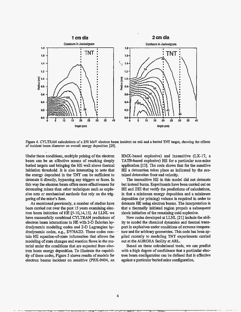
We next present a study using CYLTRAN to model an electron beam of 250 MeV on a buried generic TNT target [20]. Figure 4 shows the results in terms of en- ergy deposition for a high current pulse, for two different beam diameters incident on the soil surface. In general one observes the characteristic spread of the beam as it penetrates the soil with contours of 25-75 Jlg in the 10 cm TNT zone beginning at 20 cm depth for the 1 cm radius beam and 20-60 Jlg for the 2 cm radius beam. There is significant deposition in the soil in fiont of the TNT. This energy deposition is sufficient to vaporize water and other volatile compounds in the intervening soil, leading to blow-off and dispersal of material.
1 cm dia 2 cm dia
1.8
1.6
1.4
1 2
1.0 c - v) ; 0.8 a
0.6
0.4
0 2
0.0
Contours in Jouleslgram I . 8
: TNT : I 8 8 8 m .
0 5 10 15 20 25 30 35 40
Contours in Jouledgram . .
0 5 1 0 1 5 2 0 2 5 3 0 3 5 ~ I
Figure 4. CYL,TRAN calculations of a 250 MeV electron beam incident on soil and a buried TNT target, showing the effects of incident beam diameter on overall energy deposition [20].
Under these conditions, multiple pulsing of the electron beam can be an effective means of reaching deeply buried targets and bringing the HE well above thermal initiation threshold. It is also interesting to note that the energy deposited in the TNT can be sufficient to detonate it directly, bypassing any triggers or fuzes. In this way the electron beam offers more effectiveness for detonating mines than other techniques such as explo- sive nets or mechanical methods that rely on the trig- gering of the mine's fbze.
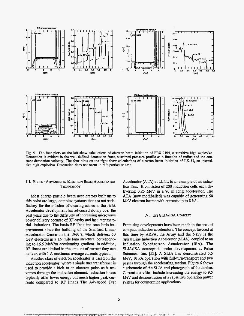
As mentioned previously, a number of studies have been carried out over the past 15 years examining elec- tron beam initiation of HE [5-10,14,15]. At LLNL we have successfully combined CYLTRAN predictions of electron beam interactions in HE with 2-D Eulerian hy- drodynamic modeling codes and 2-D Lagrangian hy- drodynamic codes, e.g., DYNA2D. These codes con- tain HE equation-of-state information that allows the modeling of state changes and reaction flows in the ma- terial under the conditions that are expected from elec- tron beam energy deposition. To illustrate the capabil- ity of these codes, Figure 5 shows results of models for electron beams incident on sensitive (PBX-9404, an
HMX-based explosive) and insensitive (LX-17, a TATB-based explosive) HE for a particular non-mine application [13]. The code shows that for the sensitive HE a detonation takes place as indicated by the sus- tained detonation front and velocity.
The insensitive HE in this model did not detonate but instead bums. Experiments have been carried out on HE and ME that veri@ the predictions of calculations, in that a minimum energy deposition and a minimum deposition (or priming) volume is required in order to detonate HE using electron beams. The interpretation is that a thermally initiated region propels a subsequent shock initiation of the remaining cold explosive.
New codes developed at LLNL [21] include the abil- ity to model the chemical dynamics and thermal trans- port in explosives under conditions of extreme tempera- ture and for arbitrary geometries. This code has been ap- plied recently to modeling TNT experiments carried out at the AURORA facility at AIU.
Based on these calculational tools, we can predict with a high degree of confidence that a particular elec- tron beam configuration can be defined that is effective against a particular buried mine configuration.
c
f
Fig. 5. The four plots on the left show calculations of electron beam initiation of PBX-9404, a sensitive high explosive. Detonation is evident in the well defined detonation front, sustained pressure profile as a function of radius and the con- stant detonation velocity. The four plots on the right show calculations of electron beam initiation of LX-17, an insensi- tive high explosive. Detonation does not occur in this particular case.
111. RECENT ADVANCES IN ELECTRON BEAM ACCELERATOR TECHNOLOGY
Most charge particle beam accelerators built up to this point are large, complex systems that are not satis- factory for the mission of clearing mines in the field. Accelerator development has advanced slowly over the past years due to the difficulty of increasing microwave power delivery because of RF cavity and insulator mate- rial limitations. The basic RF linac has seen little im- provement since the building of the Stanford Linear Accelerator Center in the 1 9 6 0 ' ~ ~ which delivers 50 GeV electrons in a 1.9 mile long structure, correspond- ing to 16.5 MeVlm accelerating gradient. In addition, RF linacs are limited in the amount of current they can deliver, with 1 A maximum average currents typical.
Another class of electron accelerator is based on the induction accelerator, where a single turn transformer is used to provide a kick to an electron pulse as it tra- verses through the induction element. Induction linacs typically offer lower energy but much higher peak cur- rents compared to RF linacs The Advanced Test
Accelerator (ATA) at LLNL is an example of an induc- tion linac. It consisted of 200 induction cells each de- livering 0.25 MeV in a 70 m long accelerator. The ATA (now mothballed) was capable of generating 50 MeV electron beams with currents up to 8 kA.
IV. THE S L M S A CONCEPT
Promising developments have been made in the area of compact induction accelerators. The concept favored at this time by AITPA, the Army and the Navy is the Spiral Line Induction Accelerator (SLIA), coupled to an Induction Synchrotron Accelerator (ISA). The SLINISA concept is under development at Pulse Sciences, Inc. [22]. A SLIA has demonstrated 5.5 MeV, 10 kA operation with full-turn-transport and two passes through the accelerating section. Figure 6 shows a schematic of the SLIA and photograph of the device. Current activities include increasing the energy to 9.5 MeV and demonstration of a repetitive operation power system for countermine applications.

9
alnporu fiugwalaioe q6nOJql ssed qiea q l ! ~ weaq 0) pappe a

Mine-killing Electron beam generator Magnetic beam
Electron beam penetrates soil and instantaneously deposits "kill" energy in HE of buried mine
Fig. 7. Notional concept of an electron beam system for detecting and clearing land mines and schematic of SLIMSA sys- tem (return-radiation sensor system not shown).
VI. EMERGING ACCELERATOR TECHNOLOGIES
At the present time a new accelerator concept called the two-beam or relativistic klystron is being studied. This accelerator combines the induction linac with an RF linac, with the induction linac used to generate the RF drive power. This concept has been recently been approved for fhding and the first generation prototypes are under construction by a joint LLNL/Lawrence Berkeley Laboratory collaboration..
While the two beam accelerator offers promise for the next generation of large laboratory-based linacs for basic
research (the Next Linear Collider, or NLC), it is un- likely to be easily adapted to the mission of clearing mine fields in the short term.
Another development is in the area of super-insulator technology, which combines dielectrics and metals in alternating layers to provide structures capable of ex- tremely high standoff voltages. Work on super-insula- tors is taking place at LLNL and elsewhere and promises to allow very high accelerating gradients in short, high current pulses [24].
Using advanced compact accelerator technologies such as the above it is probable that within the next few
7

250 MeV, 0 x,, 5 kA 250 MeV, 1.5 xo, 5 kA
E L E L I I
CK 05
4 a 22 E
10.00
n n
m U v ’t ‘c 0 0 Jz c I
1.00
rx 0.10 2 230 457 685 912
Zeta (cm)
34
32
30
28
26
24
22
Zeta (cm)
Fig. 8. BEAMFIRE calculation of electron beam propagation showing stable and unstable propagation conditions. The vertical axis is the ratio of the beam initial radius to its propagation radius at a particular point (solid line is beam half- width and dashed line is beam RMS width). The horizontal axis is a measure of the distance from the beam front. Thus the figure on the left shows stable propagation for about 900 cm at this instant in time with beam trumpeting occuring only in the last 50 - 100 cm. The figure on the right shows the detrimental effect of launching the beam through 1.5 radiation lengths of material. Note the change in scale in the right hand figure from log to linear and also the suppressed zero.
years a -200 MeV high current linac could be imple- mented in a physical space that could fit onto a standard tank chassis.
VII. CURRENT AND FUTURE ACTIVITIES IN ELECTRON BEAM MINE DETECTIONAND CLEARING
There are currently a small number of minimally funded activities studying electron beam interrogation and detonation of mines. While it has been recognized that electron beams are effective against mines, the lack of a fieldable machine and a mission concept has pre- vented significant funding fkom being applied to the de- velopment of a viable system. Instead motivated indi- vidual researchers and laboratories have applied internal funding and small amounts of money from the Army and Navy to study the problem.
Last year’s MOU for $6M was signed between the Army, the Navy and ARPA to provide funding for both accelerator development and effects studies. The bulk of the funding has gone towards accelerator development and only a small amount has been devoted to experi- ments and calculations in support of systems develop- ment. It is clear that more work is needed in the latter area, particularly to address the effects of beam propaga-
tion, intervening materials, wet and dry soils, etc. Additionally the efficacy of electron beams for detona- tion of surf-zone and underwater mines is completely unexplored and could prove to be viable.
In the area of electron beam modeling, new Monte Carlo codes are becoming available that calculate fully coupled electron-photon-neutron particle generation and transport. Neutron heating and transport can become an important issue for beam energies above 20 MeV. Neutron generation and capture can be exploited for de- tection of buried mines. Collateral effects of electron beams also need to be understood. These include effects on operating personnel in the field, and radiation effects on the environment, including radioactivation of ele- ments in the soil as well as sterilization of biological systems in the soil. Preliminary measurements of 115 MeV electrons on dry sand indicate that activation products are short-lived, with few-second to few-minute half-lives. Soil sterilization using scanned electron beams may actually have commercial applications in agriculture, and electron beams are already commer- cially available for sterilizing medical apparatus and food products.
Beam propagation in the atmosphere is another area that is being addressed using newly developed codes that combine the physics of electron interactions in the

Fig. 9. Photographs of the ATA at LLNL demonstrating stable and unstable propogation of a 50 MeV, 8 kA electron beam in the atmosphere. In the upper photograph the beam is observable as a faint horizontal line approximately 1/3 from the top. The beam is emerging from the left and is propagating approximately 20 meters. The lower photograph shows the severe trumpeting of the beam under improper launch conditions.
atmosphere with the effects of high current density. The BEAMFIRE code, developed by researchers from LLNL and LBL, has been used to model energetic high current electron beam propagation in air [25]. Figure 8 shows results from this code that indicate beam refocusing (pinching) can occur upon extraction from the accelera- tor with reasonable propagation lengths of interest for a proper standoff mine clearing system.
Experimentally, the ATA demonstrated that intense energetic electron beams can be made to propagate many meters in air without dispersion. Figure 9 shows a photograph of a properly conditioned ATA beam propagating a distance of about 20 m before dissipating. Also shown is an example of instability in beam propa- gation if the electron beam is not properly prepared for launch into the atmosphere.
As was mentioned earlier, there is no single accelera- tor available yet that combines both high energy and high current operation in a single beam. Until such a
machine becomes available, a number of machines are being used to understand the separate effects of high en- ergy and high current electron interactions in soils, HE and mines. LLNL's 160 MeV linac is a unique resource in the US for high energy effects studies in that it is the only remaining linac that is operated full time for use as both a basic research and weapon effects machine. The facility includes a number of large experimental caves and neutron time-of-flight lines. Other linacs such as the ORELA facility at Oak Ridge and the Naval Post-grad- uate School Linac also offer the capability for high en- ergy electrons. Lower energy, higher current machines include the AURORA facility, LLNL's FXR (17 MeV, 2 kA in a 70 ns pulse, with 2-pulse capability), and PIXY (a 6 MeV diode machine, similar to ECTOR) at LANL. We have shown that a combination of experi- ments at these machines can yield valuable information for input to system models to evaluate the effectiveness of electron beamsfor destroying mines.
VIII. CHARGED PARTICLE BEAM COUNTERMINE IV~ISSIONS OF INTEREST
Several countermine missions are envisioned that are well-suited to the capabilities of a Charge Particle Beam Counter Mine (CPB-CM) system. These include:
1.
2.
3.
Route Clearing - clearing established routes to en- sure Lines of Communication (LOC)
Area Clearing - clearing defined minefield where the area has been secured and the entire minefield is to be neutralized
Assault Breaching - penetration of the minefield while under enemy fire where speed of advance is critical; CPB-CM system could support primary forward breachers (e.g., plows, rakes and flails)
Area clearing as defined above applies to both mili- tary and non-military operations, for example, clearing of mines in third world countries where it is needed to restore land to agricultural and residential use.
As a part of the evaluation of CPBs for the above missions, a system engineering study has been per- formed by Jason Associates Corporation [20] that evalu- ates effective speeds, and power requirements, under as- sumptions of sensor performance and false alarm rates. Results of the analysis include system advance rate and power consumption as a function of sensor performance, mine burial depth, and beam energy. I summarize here the main points of this study:
1.
2.
3.
4.
5 .
6.
Sensor performance (detection rate, false alarms) is an important system driver. False alarm rates less than O.Ol/m* are needed.
System advance rate is not very sensitive to either mine burial depth or mine detonation threshold.
Advance rates of a few mph are possible with near- term sensor performance goals.
High advance rates (> 8 mph) are possible if more advanced sensor performance becomes available.
Average system power requirement is in the range of a few hundred kW under most conditions.
For a given false alarm rate there exists a detection mode speed above which additional performance gains are not achieved.
10
7. Beam energy-of about 250 MeV is optimal al- though beam energies as low as 150 MeV yield ac- ceptable performance.
8. System standoff fiom the mine in kill mode is op- timal at about 5 m.
IX. SUMMARY AND RECOMMENDATIONS
It is clear that the mission of CPB-CM is in an evo- lutionary state as the capabilities of the system are demonstrated over the next few years. Vital to the de- velopment of CPB-CM is the development of better working relationships with the user(s) in order to guide the development of the system. Part of this relationship includes regular top-level situation-audits of CPB tech- nology for countermine missions qs well as the receipt of guidance and data on potential CPB-CM mission area requirements and alternative systems that might also address those missions. In this way actions can be identified and a schedule developed to produce a roadmap to assess CPB technology utilization in coun- termine mission areas.
X. RELATIONSHIP TO OTHER EFFORTS
While this paper has concentrated on charged parti- cle beam disablement of mines, at LLNL a number of activities in the area of mine detection and disablement are being coordinated in a Mine Warfare Working Group chaired by Dr. Milton Finger. A number of pre- sentations are being made at this Symposium by other LLNL researchers and collaborators. ,The LLNL Mine Warfare Working group meets regularly to discuss and coordinate mine-related activities at LLNL, to identify potential new programs as they are announced, with the goal of developing the necessary combination of mine detection and clearing technologies to solve the needs of the military and civilian agencies involved in this important mission. LLNL maintains a mine field test area with a number of different types of anti-personnel and anti-tank mines at the Nevada Test Site for fielding and testing both detection and disablement concepts. We hope that this Symposium will spark the beginning of a new era in mine warfare and countermine activities. We look forward to the establishment of new partnerships and a new level of cooperation between the Army, Navy, ARPA, Industry and the National Laboratories.

ACKNOWLEDGMENTS
I would like to acknowledge the contributions of a number of researchers whose work is presented here and in the references. In particular, Dr. Adrian C. (Chip) Smith and Dr. Jay Boudreau of Jason Associates Corporation have been long-standing proponents of electron beam detection and disablement of land mines and have provided me with a wealth of information on the system concepts touched upon only briefly in this paper. Dr. Smith and Dr. Nancy Chesser of Directed Technologies, Inc., also provided me with extremely useful comments and suggestions regarding many of the topics in this paper. Dr. Sidney Putnam of Pulsed Sciences, Inc. graciously provided me with the photo- graph of the SLIA. Mr. Klaus Kerris of ARL and his colleagues have performed the most recent tests of HE detonations at ARL. Dr. Tom Phillips and Mr. Joe Mauger performed the soil exposures and data analysis at the LLNL 160 MeV Linac. Much of the early work in modeling electron beam interactions in HE was performed by LCDR Steven Miller (Ret.), while serv- ing as a Military Research Associate at LLNL between 1987 and 1990. This work was performed by LLNL un- der the auspices of the USDOE Contract number W- 7405-ENG-48.
REFERENCES
[31
[41
191
H. Kruger, “A Survey of the Vulnerability of Nuclear Warheads to Particle Beams (U),” LLNL Report CD-
H. Kruger, “Charged Particle Beam Transport Experiments for BMDATC (U),” LLNL Report CD- 78-1 13, October, 1978 (SNSI). H. Kruger, “Particle Beam Weapon Effects (U),” LLNL Report CD-79-40, April, 1979 (SRD). “Charged Particle Beam Weapons (U),” J. Defense Research, Vol. 21, No. 2, DTIC AD42959 625, May,
G. Bloom, “High Explosive Shock Initiation Experiments with an Electron Beam,” LLNL Report
A. Stolovy, et a!., “Thermal Initiation of High Explosives with an Electron Beam,” Naval Research Laboratory Report 8350, November, 1979. W. Bookless, ‘‘Electron Beam Initiation of HE (U),” LLNL Report CD-81-149, October, 1981 (S). A. Stolovy, et a!., “Exothermic Reactions in TATB Initiated by an Electron Beam,” J. Chem. Phys., 78( I), January, 1983. E. W. Pogue, “Electron Beam Initiation of TATB (U),” LANL Document LA-CP-85-149, 1985. (SNSI).
77-147, July, 1977 (SRD).
1992 (S-NOFORN-FRD-WNINTEL) .
D-79-4, March, 1979.
[lo] S. G. Miller, “Electron Beam Initiation of HE: ECTOR - August, 1987 (U),” LLNL D Division Document #CD-89-0220 (SNSI).
[l 11 C. R. Wuest, “Electron Beam Lethality Assessment for Nuclear Warheads (U),” LLNL D Division Document #CD-89-0274, November, 1989 (SRD).
[12] C. R. Wuest, W. E. Farley, “Calculation of the Neutron Population in Complex Targets Exposed to an Energetic Electron Beam and Comparison to Experiment (U),” LLNL D Division Document #CD- 88-0174, published in the Proceedings of the 1988 Nuclear Explosive Code Developers Conference, 11,
[13] S. G. Miller, “Progress in Electron Beam Lethality Assessment (U),” LLNL Report CD-89-0082 (SRD).
[14] F. Chambers, “Presentations on the ATA Airline I Experiment at the Annual Propagation Physics Review, September, 1987,” UCID-2123 1.
[15] S. G. Miller, W. E. Farley, C. R. Wuest, D. Demske, “ECTOR Mine Exposure Experiment (U),” LLNL Report CD-89-0012 (SNSI).
[I61 W. R. Nelson, H. Hirayama and D. W. 0. Rogers, “The .EGS4 Code System,” SLAC-Report-265, December, 1985.
[I71 J. Halbleib, “Integrated TIGER Series of Coupled Electron-Photon hfonte Carlo Code Systems,”
p. 337 (1988) (SRD).
ORNL DOC. CCC-467ATS3.0 (1994). [ 181 J. F. Briesmeister, Ed., “MCNP - A General Monte
Carlo N-Particle Transport Code, Version 4A,” Los Alamos National Laboratory Document LA-12625- M (1993).
[19] A. C. Smith and N. J. Chesser, eds., “Proceedings of the CPB Effectiveness vs. Mines Workshop,” Arlington, VA, June 11, 1993, Ballena Systems Corporation Document 93-0012, September, 1993
[20] Studies performed by Jason Associates Corporation, Lodi, CA and Los Alamos, NM.
[21] Dr. William Tao and Dr. Albert Nichols, I11 of LLNL have developed and applied the TOPAZCHEM code to the problem of mine clearing.
[22] Dr. Sidney Putnam, Titan Pulsed Sciences, Inc. 600 McCormick St., San Leandro, CA 94577.
[23] S. Payan, et a!., “High Gradiant Insulator Tech- nology for the Dielectric Wall Accelerator,” to be submitted to the 1995 International Conference on High Energy Accelerators, Dallas, TX, May 1995.
[24] J. R. Clifford, K. W. Habiger i d R. B. Miller, “Final Report for Defense Advanced Research Projects Agency and U.S. Army Belvoir Research, Development and Engineering Center Contract #DAAK70-88-C-0033,” submitted to U. S. Army Research, Development and Engineering Center, May 6, 1993 by Titan Advanced Innovative Technol- ogies, Titan Document # TAlT-R-152.
[25] G. DePeso, W. Fawley and G. F. Simonson, “Electron Beam Modeling using BEAMFIRE,” unpublished, August 30, 1994.